Gamma-ray Spectroscopy An introduction: gamma rays ... - NSCL
62
Gamma-ray Spectroscopy An introduction: gamma rays, detectors, spectrometers Exotic Beams Summer School 2011, MSU Exotic Beams Summer School 2011, MSU Dirk Weisshaar (NSCL)
Transcript of Gamma-ray Spectroscopy An introduction: gamma rays ... - NSCL
Gamma-ray Spectroscopy
An introduction:gamma rays, detectors, spectrometers
Exotic Beams Summer School 2011, MSUExotic Beams Summer School 2011, MSU
Dirk Weisshaar (NSCL)

Outline
BasicsGamma rays, their interactions, and basic properties of a spectrum
Gamma-Ray DetectorsGamma-Ray DetectorsScintillators, Semiconducter, Ge-detectors and modern ones
Gamma-Ray SpectrometerJust many detectors? Resolving power
SeGA, CAESAR, GAMMASPHERE, GRETA/GRETINA
Literature
• “Techniques for Nuclear and Particle PhysicsExperiments” by W.R. Leo(my recommendation, but out-of-date in some areas)
• “Measurement And Detection Of Radiation”by N. Tsoulfanidisand S. Landsbergerby N. Tsoulfanidisand S. Landsberger(recent 3rd edition, pretty up-to-date)
• “Radiation Detection And Measurement” by G. Knoll(The device physicists’ bible, but beginners may get lost soon…)
(most pictures presented in this lecture are taken from those books and referenced as [LEO], [TSO], [KNO])

Gamma-ray transition
A list of decay modes for an excited state of a nucleus:-β+, β-, Electron-Capture (e.g. 177Lum)-Proton, Neutron emission (e.g. 53Com)-Alpha emission (e.g. 211Pom)-Fission (e.g. 239Pum)-Internal Conversion-Emission of gamma ray
Gamma-ray emission is usually the dominant decay mode
Measurement of gamma rays let us deduce:Energy, Spin (angular distr./correl.), Parity (polarization), magnetic moment, lifetime (recoil distance Doppler-shift), ….
of the involved nuclear levels.
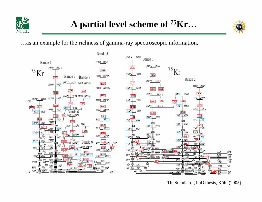
A partial level scheme of 75Kr…
…as an example for the richness of gamma-ray spectroscopic information.
Th. Steinhardt, PhD thesis, Köln (2005)

Interaction of gamma rays with matter
Photo effect
Compton scattering
A photoelectron is ejectedcarrying the complete
Elastic scattering of a gamma ray off a free electron.
Pair production
gamma-ray energy (- binding)gamma ray off a free electron.A fraction of the gamma-ray energy is transferred to the Compton electron
If gamma-ray energy is >> 2 moc2
(electron rest mass 511 keV), a positron-electron can be formed in the strong Coulomb field of a nucleus.This pair carries the gamma-ray energy minus 2 moc2 .
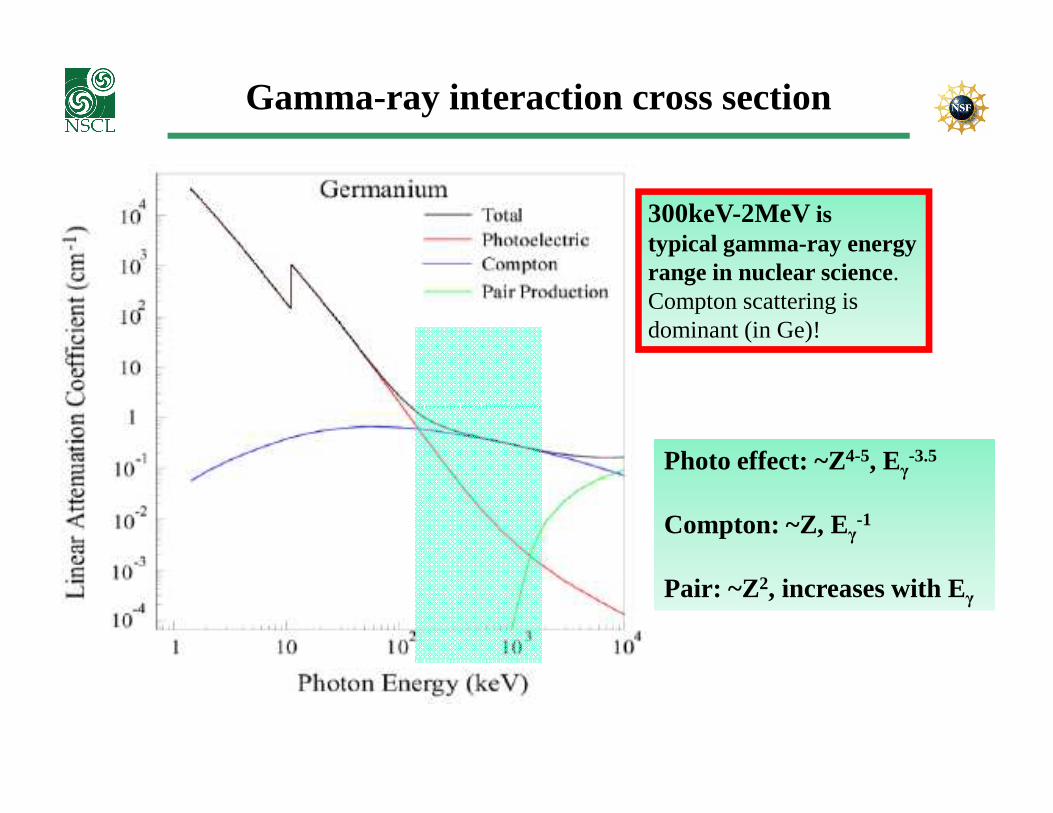
Gamma-ray interaction cross section
300keV-2MeVistypical gamma-ray energyrange in nuclear science.Compton scattering isdominant (in Ge)!
Photo effect: ~Z4-5, Eγ-3.5
Compton: ~Z, Eγ-1
Pair: ~Z2, increases with Eγ
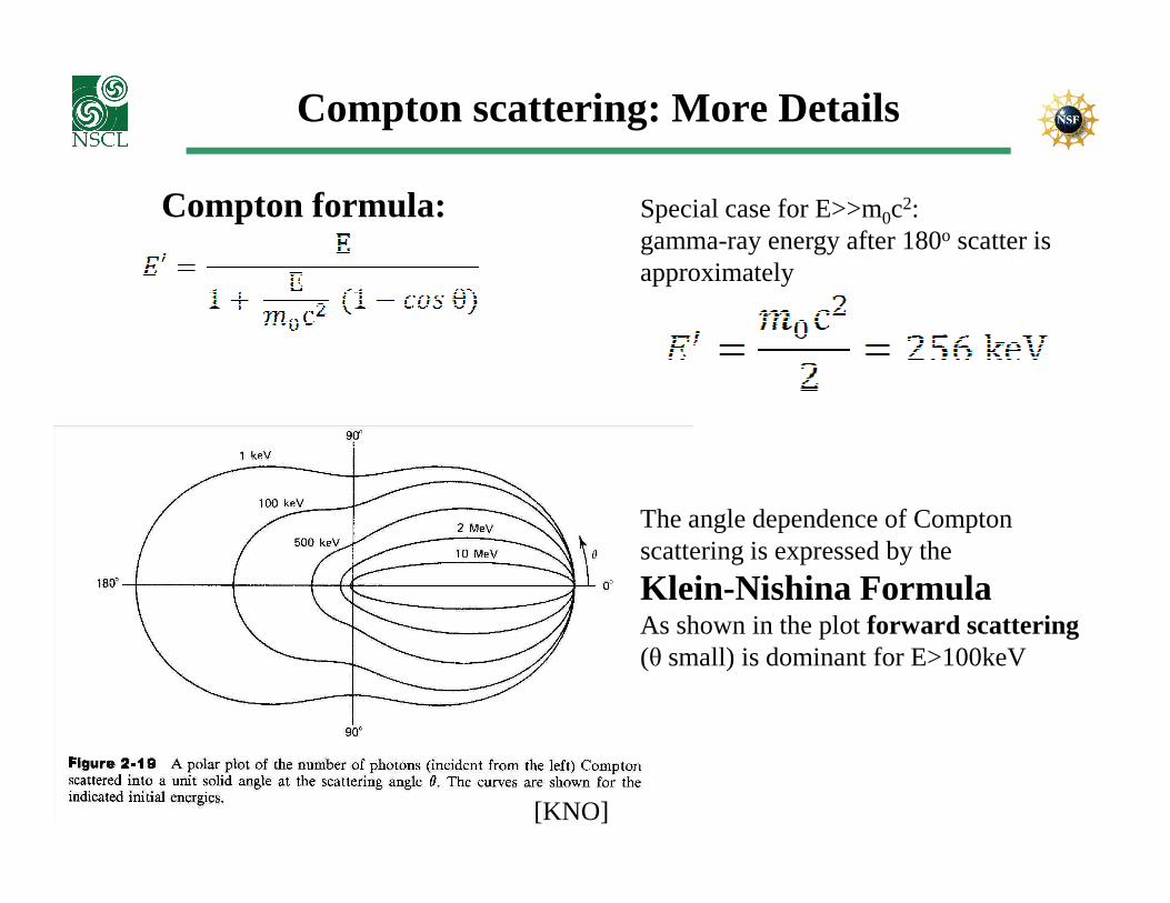
Compton scattering: More Details
Compton formula: Special case for E>>m0c2:gamma-ray energy after 180o scatter isapproximately
[KNO]
The angle dependence of Comptonscattering is expressed by the
Klein-Nishina FormulaAs shown in the plot forward scattering(θ small) is dominant for E>100keV
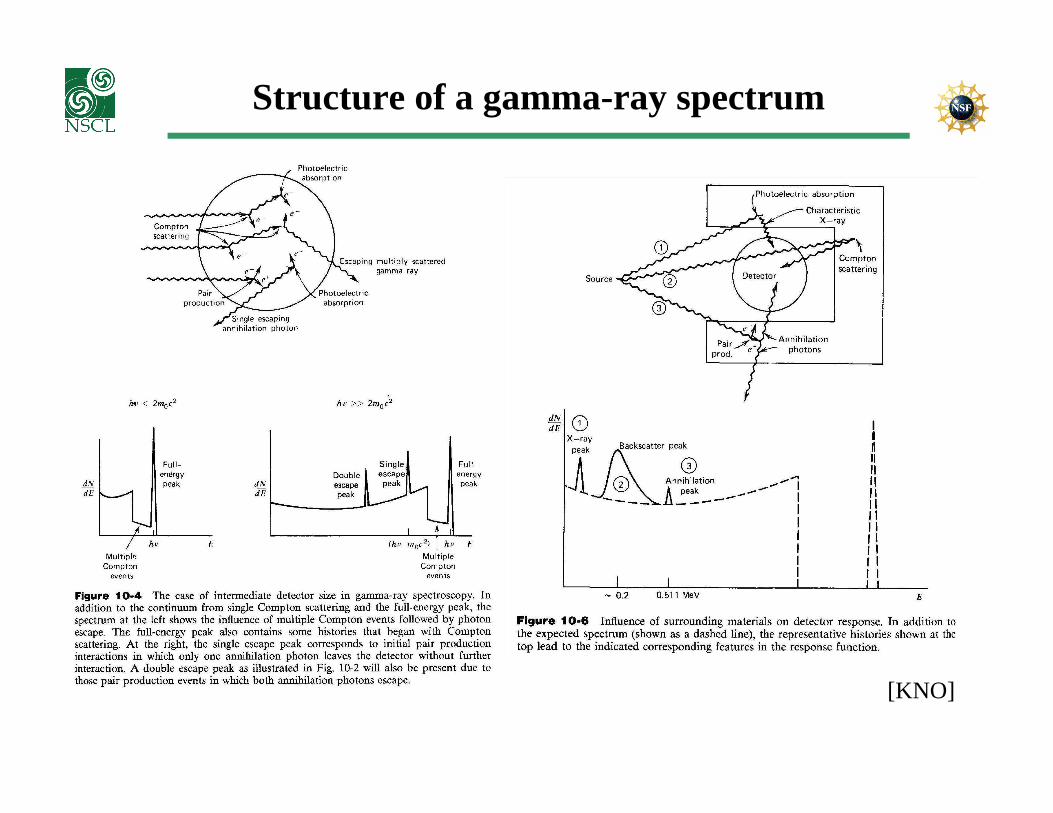
Structure of a gamma-ray spectrum
[KNO]

Scintillator
Scintillators are materials that produce ‘small flashes of light’ when struck by ionizing radiation (e.g. particle, gamma, neutron).This process is called ‘Scintillation ’.
Scintillators may appear as solids, liquids, or gases.
Major properties for different scintillating materials are:Major properties for different scintillating materials are:�Light yield and linearity (energy resolution)
�How fast the light is produced (timing)
�Detection efficiency
Organic Scintillators (“plastics”):Light is generated by fluorescence of molecules; usually fast, but low light yield
Inorganic Scintillators:Light generated by electron transitions within the crystalline structure of detector;usually good light yield, but slow
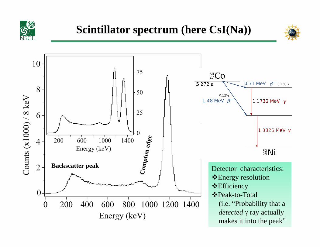
Scintillator spectrum (here CsI(Na))
6
10
8
Co
un
ts (
x1
00
0)
/ 8
keV
25
50
75
0
0 1000 1200
4Energy (keV)
Energy (keV)
2
1400
200 400 600 800 1400
Co
un
ts (
x1
00
0)
/ 8
keV
200 600 1000
0
Backscatter peak Detector characteristics:�Energy resolution�Efficiency�Peak-to-Total
(i.e. “Probability that a detected γ ray actually makes it into the peak”
Resolution
25
50
75
0
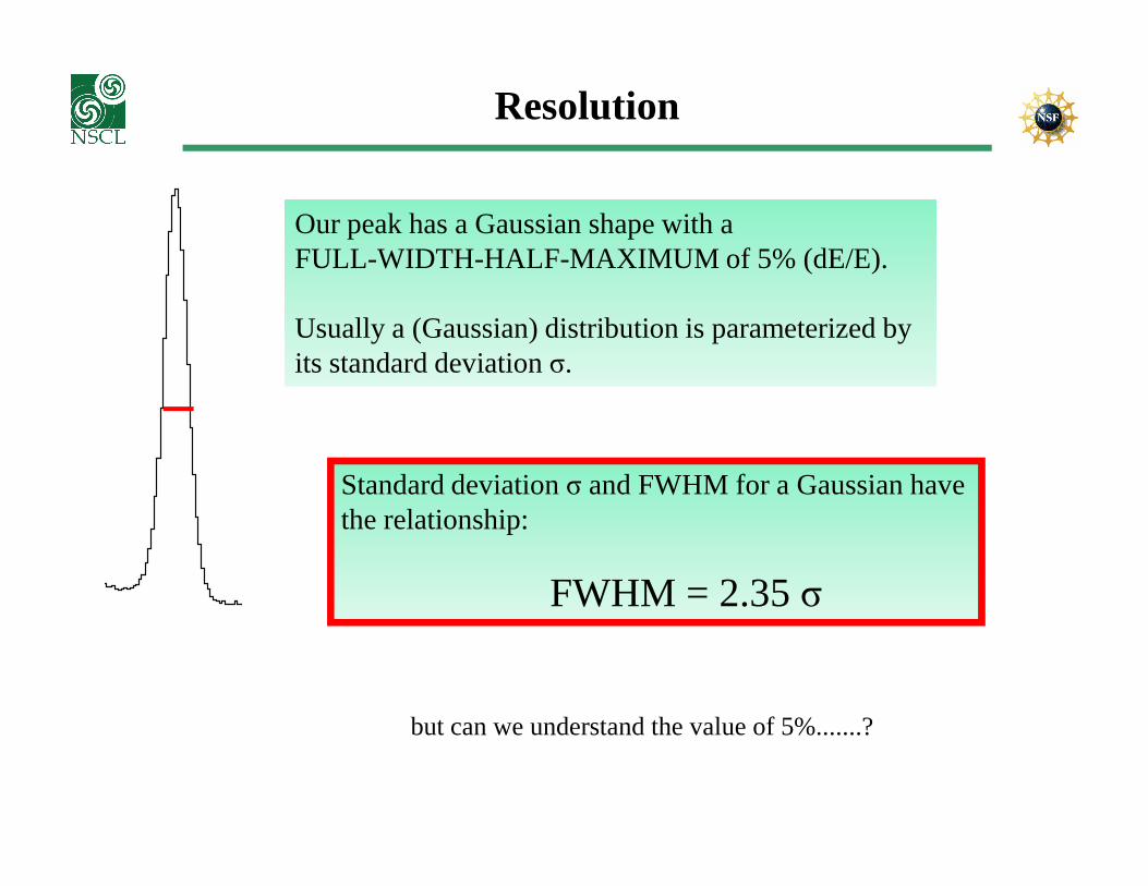
Our peak has a Gaussian shape with a FULL-WIDTH-HALF-MAXIMUM of 5% (dE/E).
Usually a (Gaussian) distribution is parameterized by its standard deviation σ.
Standard deviation σ and FWHM for a Gaussian havethe relationship:
FWHM = 2.35 σ
but can we understand the value of 5%.......?

Let’s roll a dice: Binomial Distribution
What is the probability P(x) to roll x times a ‘six’ if you try n times? Answer: The binomial distribution (with p = 1/6)
The mean value
for the bin. dist. is np
And the variance
is np(1-p).
Poisson statistics
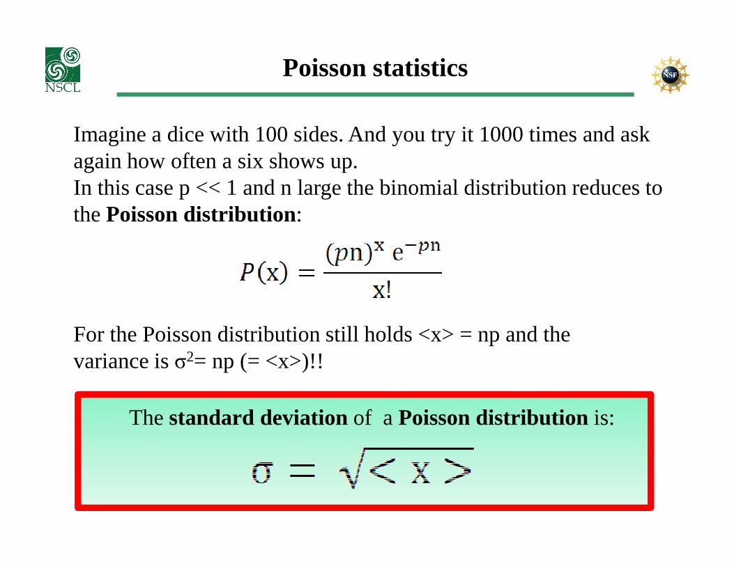
Imagine a dice with 100 sides. And you try it 1000 times and askagain how often a six shows up.In this case p << 1 and n large the binomial distribution reduces tothe Poisson distribution:
For the Poisson distribution still holds <x> = np and the variance is σ2= np (= <x>)!!
The standard deviation of a Poisson distribution is:
Poisson statistic and nuclear science
Mostly counting experiments are done like “How many events C do I count if a beam of nuclei B hit a target A ?” The cross sectionfor producing event C is low, beam means many nuclei B are shoton target nuclei A. So the counting statistics will follow the PoissonDistribution and if we count N events C, its error is √N.
Same applies for our scintillation detector:Same applies for our scintillation detector:An energetic particle is traveling through the detector (e.g. electronfrom gamma ray interaction). Per travelling length dx this particle may produce a scintillation photon, which may make it to the photo-cathode, which may be converted into a photo-electron in the PMTand contribute to the signal. Example: CsI(Tl) does 39.000 photons per 1 MeV gamma. Light collection and PMT quantum efficiency ~15% � ~6000 photons are collected in average. σ = √6000=77.FWHM=2.35 * 77 = 180. �dE/E = 180/6000 = 3%.
Semiconductor detectors
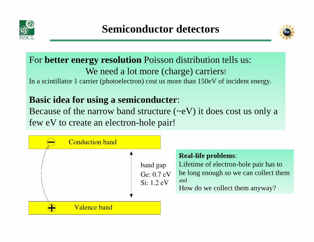
For better energy resolution Poisson distribution tells us: We need a lot more (charge) carriers!
In a scintillator 1 carrier (photoelectron) cost us more than 150eV of incident energy.
Basic idea for using a semiconducter:Because of the narrow band structure (~eV) it does cost us only a few eV to create an electron-hole pair!few eV to create an electron-hole pair!
Real-life problems:Lifetime of electron-hole pair has tobe long enough so we can collect themand
How do we collect them anyway?
n- and p-doped semiconductor material
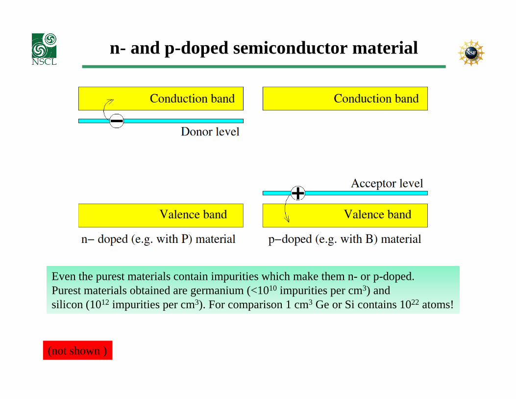
Even the purest materials contain impurities which make them n- or p-doped. Purest materials obtained are germanium (<1010 impurities per cm3) and silicon (1012 impurities per cm3). For comparison 1 cm3 Ge or Si contains 1022 atoms!
(not shown )
Depletion and reverse biasing
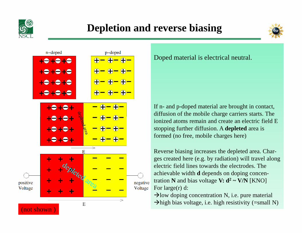
Doped material is electrical neutral.
If n- and p-doped material are brought in contact, diffusion of the mobile charge carriers starts. The diffusion of the mobile charge carriers starts. The ionized atoms remain and create an electric field E stopping further diffusion. A depletedarea is formed (no free, mobile charges here)
Reverse biasing increases the depleted area. Char-ges created here (e.g. by radiation) will travel along electric field lines towards the electrodes. The achievable width d depends on doping concen-trationN and bias voltage V: d2 ~ V/N [KNO]For large(r) d:�low doping concentration N, i.e. pure material�high bias voltage, i.e. high resistivity (=small N)
(not shown )
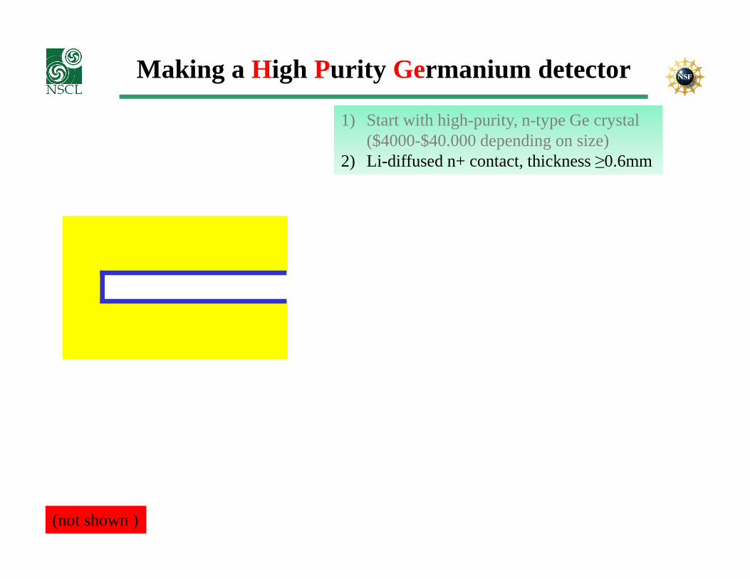
Making a High Purity Germanium detector
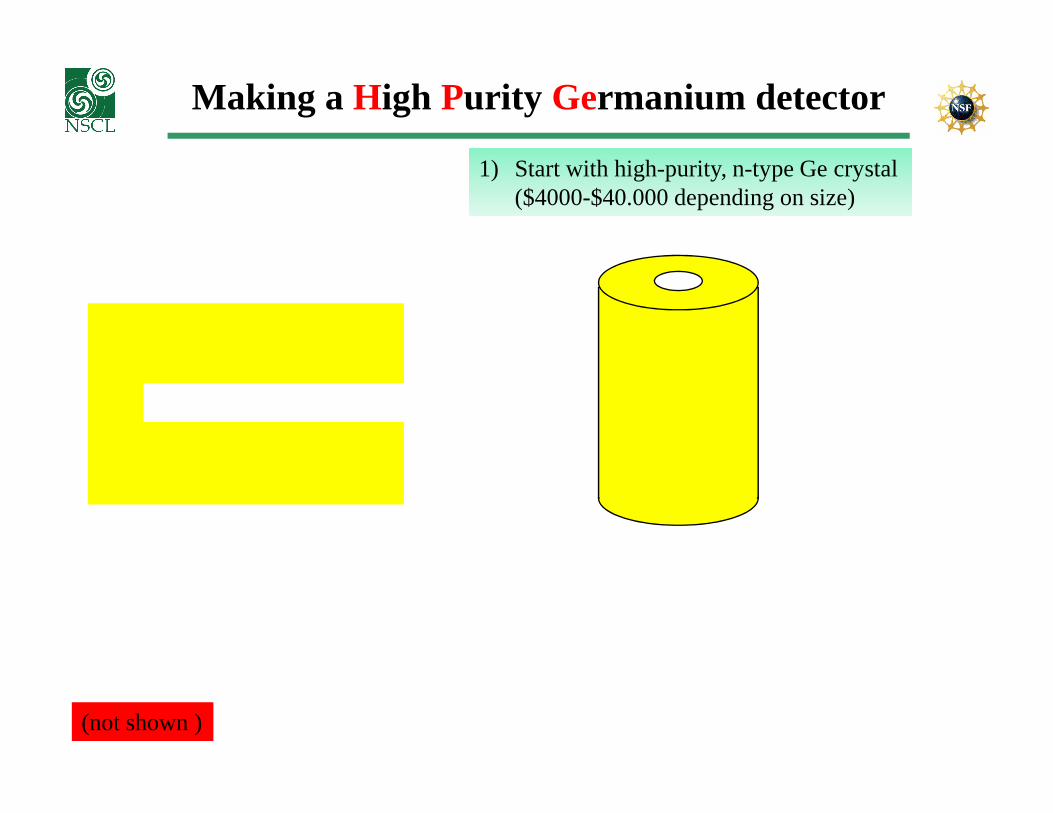
1) Start with high-purity, n-type Ge crystal($4000-$40.000 depending on size)
(not shown )
Making a High Purity Germanium detector
1) Start with high-purity, n-type Ge crystal($4000-$40.000 depending on size)
2) Li-diffused n+ contact, thickness ≥0.6mm
(not shown )
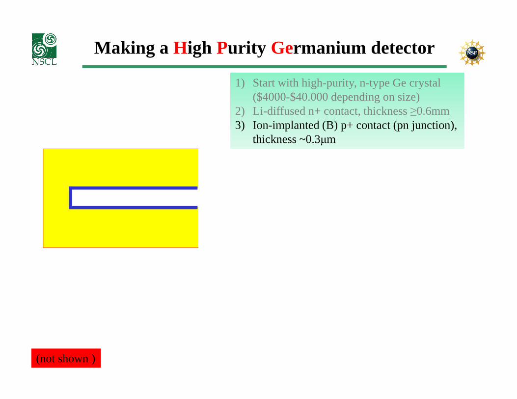
Making a High Purity Germanium detector
1) Start with high-purity, n-type Ge crystal($4000-$40.000 depending on size)
2) Li-diffused n+ contact, thickness ≥0.6mm3) Ion-implanted (B) p+ contact (pn junction),
thickness ~0.3µm
(not shown )
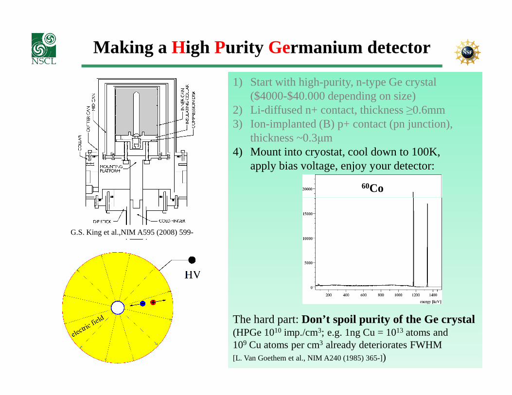
Making a High Purity Germanium detector
1) Start with high-purity, n-type Ge crystal($4000-$40.000 depending on size)
2) Li-diffused n+ contact, thickness ≥0.6mm3) Ion-implanted (B) p+ contact (pn junction),
thickness ~0.3µm4) Mount into cryostat, cool down to 100K,
apply bias voltage, enjoy your detector:
60Co
The hard part: Don’t spoil purity of the Ge crystal(HPGe 1010 imp./cm3; e.g. 1ng Cu = 1013 atoms and 109 Cu atoms per cm3 already deteriorates FWHM[L. Van Goethem et al., NIM A240 (1985) 365-])
G.S. King et al.,NIM A595 (2008) 599-
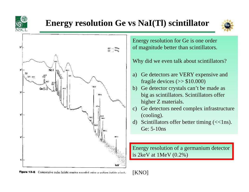
Energy resolution Ge vs NaI(Tl) scintillator
Energy resolution for Ge is one orderof magnitude better than scintillators.
Why did we even talk about scintillators?
a) Ge detectors are VERY expensive andfragile devices (>> $10.000)
b) Ge detector crystals can’t be made asbig as scintillators. Scintillatorsofferbig as scintillators. Scintillatorsofferhigher Z materials.
c) Ge detectors need complex infrastructure(cooling).
d) Scintillators offer better timing (<<1ns).Ge: 5-10ns
Energy resolution of a germanium detectoris 2keV at 1MeV (0.2%)
[KNO]
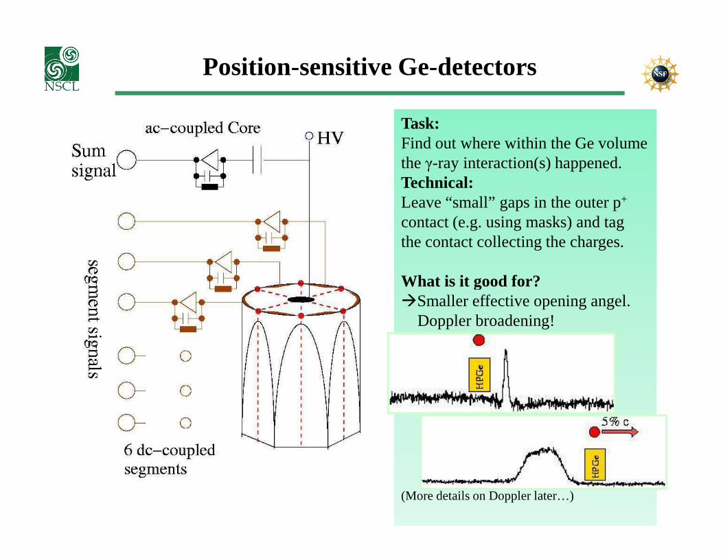
Task:Find out where within the Ge volumethe γ-ray interaction(s) happened.Technical:Leave “small” gaps in the outer p+
contact (e.g. using masks) and tagthe contact collecting the charges.
What is it good for?
Position-sensitive Ge-detectors
What is it good for?�Smaller effective opening angel.
Doppler broadening!
(More details on Doppler later…)
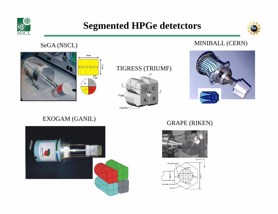
Segmented HPGe detetctors
SeGA (NSCL) MINIBALL (CERN)
TIGRESS (TRIUMF)
GRAPE (RIKEN)EXOGAM (GANIL)
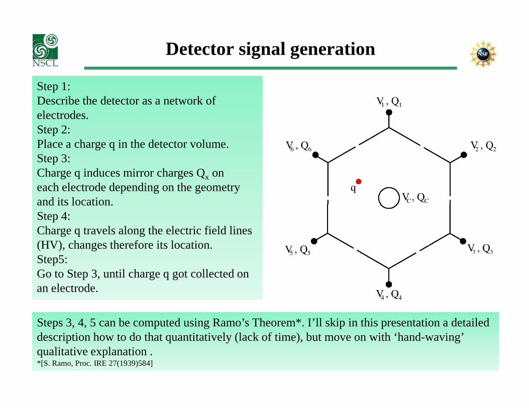
Detector signal generation
Step 1:Describe the detector as a network ofelectrodes.Step 2:Place a charge q in the detector volume.Step 3:Charge q induces mirror charges Qx oneach electrode depending on the geometryand its location.and its location.Step 4:Charge q travels along the electric field lines (HV), changes therefore its location.Step5:Go to Step 3, until charge q got collected onan electrode.
Steps 3, 4, 5 can be computed using Ramo’s Theorem*. I’ll skip in this presentation a detaileddescription how to do that quantitatively (lack of time), but move on with ‘hand-waving’qualitative explanation .*[S. Ramo, Proc. IRE 27(1939)584]
Computing Mirror Charges (1)
(not shown )
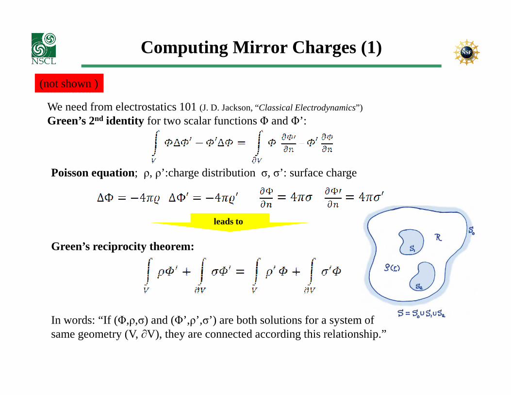
We need from electrostatics 101 (J. D. Jackson, “Classical Electrodynamics”)
Green’s 2nd identity for two scalar functions Φ and Φ’:
Poisson equation; ρ, ρ’:charge distribution σ, σ’: surface charge
Green’s reciprocity theorem:
leads to
In words: “If (Φ,ρ,σ) and (Φ’,ρ’,σ’) are both solutions for a system of same geometry (V, ∂V), they are connected according this relationship.”
Computing Mirror Charges (2)
(not shown )
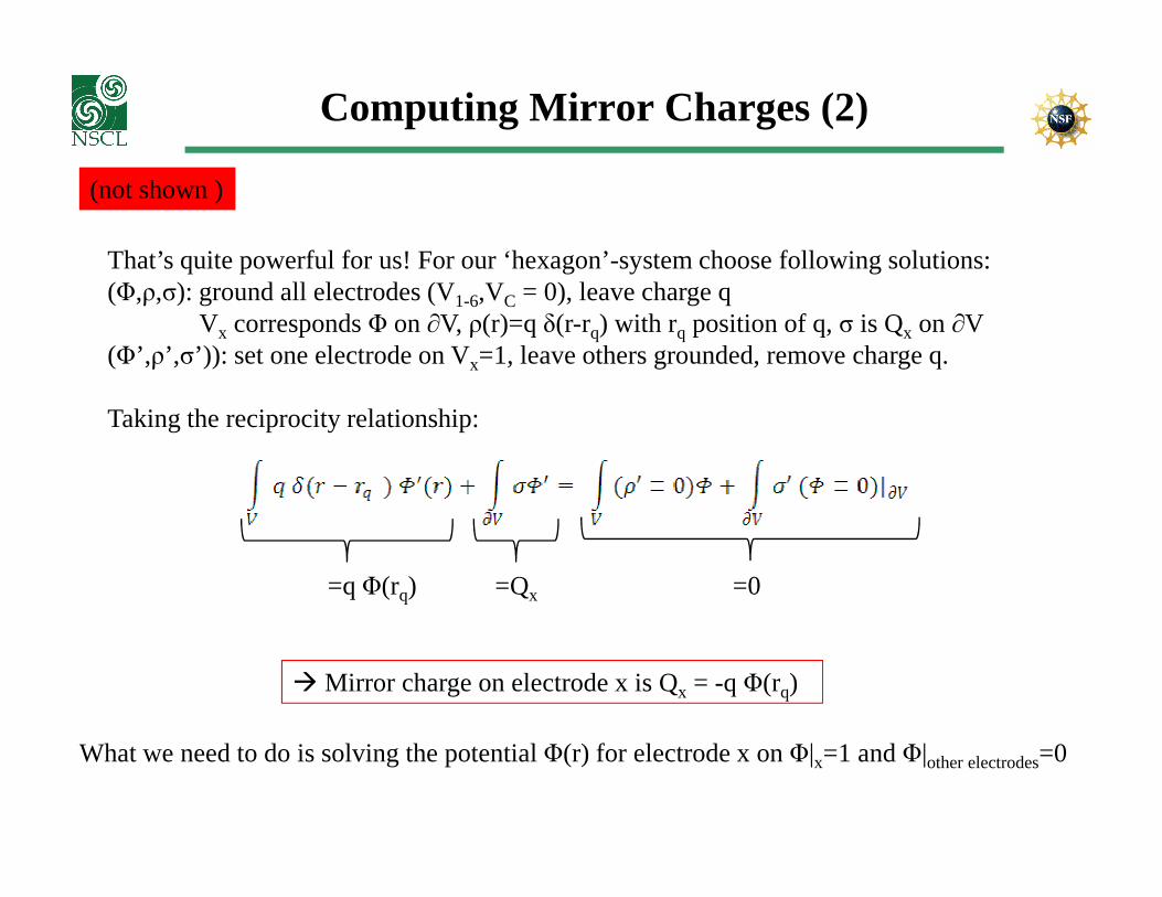
That’s quite powerful for us! For our ‘hexagon’-system choose following solutions:(Φ,ρ,σ): ground all electrodes (V1-6,VC = 0), leave charge q
Vx corresponds Φ on ∂V, ρ(r)=q δ(r-rq) with rq position of q, σ is Qx on ∂V(Φ’,ρ’,σ’)): set one electrode on Vx=1, leave others grounded, remove charge q.
Taking the reciprocity relationship:
=0=Qx=q Φ(rq)
� Mirror charge on electrode x is Qx = -q Φ(rq)
What we need to do is solving the potential Φ(r) for electrode x on Φ|x=1 and Φ|other electrodes=0
Computing Mirror Charges (3)
(not shown )
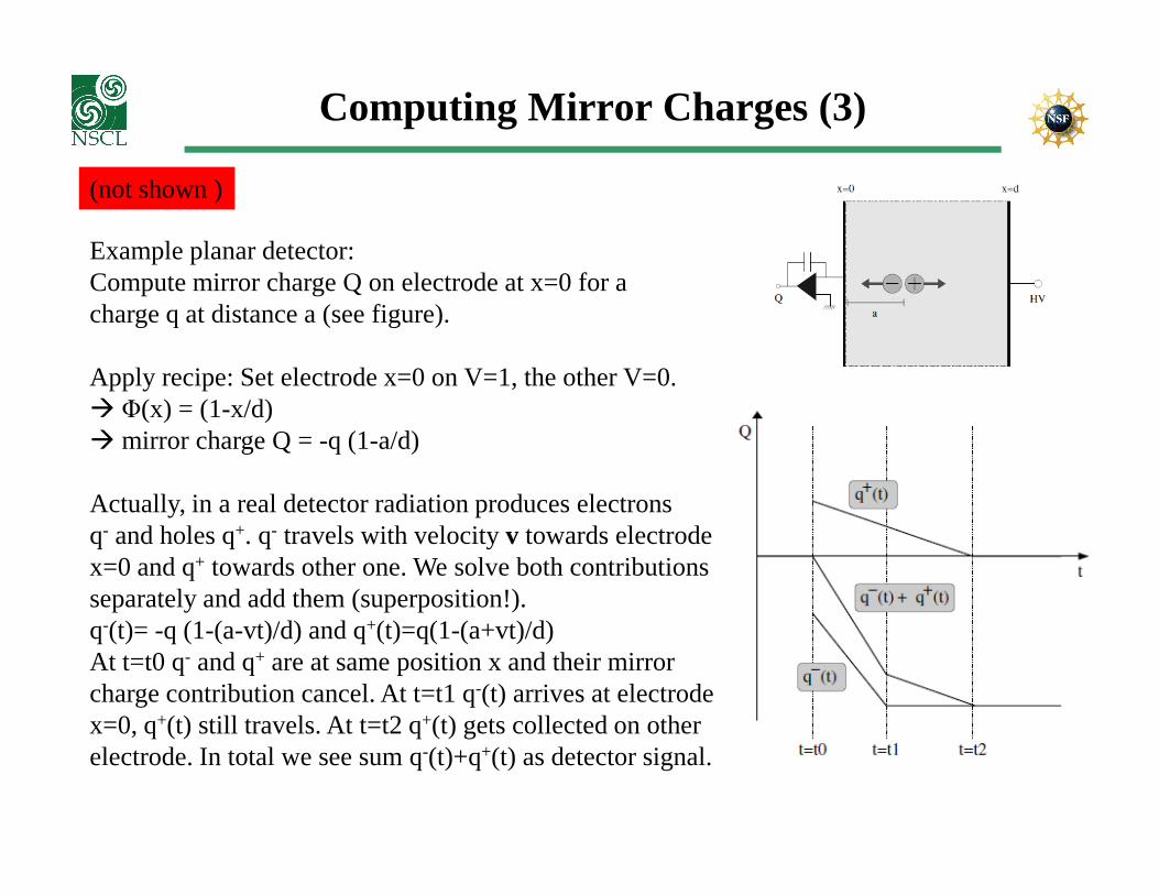
Example planar detector:Compute mirror charge Q on electrode at x=0 for acharge q at distance a (see figure).
Apply recipe: Set electrode x=0 on V=1, the other V=0.� Φ(x) = (1-x/d)� mirror charge Q = -q (1-a/d)� mirror charge Q = -q (1-a/d)
Actually, in a real detector radiation produces electrons q- and holes q+. q- travels with velocity v towards electrode x=0 and q+ towards other one. We solve both contributions separately and add them (superposition!).q-(t)= -q (1-(a-vt)/d) and q+(t)=q(1-(a+vt)/d)At t=t0 q- and q+ are at same position x and their mirrorcharge contribution cancel. At t=t1 q-(t) arrives at electrodex=0, q+(t) still travels. At t=t2 q+(t) gets collected on otherelectrode. In total we see sum q-(t)+q+(t) as detector signal.

Computing Mirror Charges (1)
(not shown )
One more step:Charge q runs with velocity v(t) (vector) along electric field lines defined by detector material, geometry and applied high voltage. It is worthwhile switching from mirrorcharge Q(t) to current i(t) induced on an electrode:
Egeo(x(t)) is called ‘geometric’ or ‘weighting field’ of dimension [1/m] and describes the electrostatic coupling. Don’t mistake it with the ‘real’ electric field in a detector which determines value and direction of v(t).This relationship
is called Ramo’s theorem [S. Ramo, Proc. IRE (1939) 584] and is usually used forcomputing of detector signals.
Exercise: Use Ramo’s theorem for solving planar and cylindrical detector geometry!

MINIBALL signals
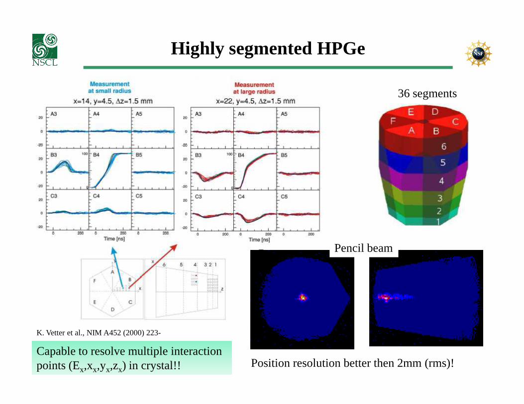
Highly segmented HPGe
36 segments
Position resolution better then 2mm (rms)!
K. Vetter et al., NIM A452 (2000) 223-
Pencil beam
Capable to resolve multiple interaction points (Ex,xx,yx,zx) in crystal!!
36-fold segmented detectors
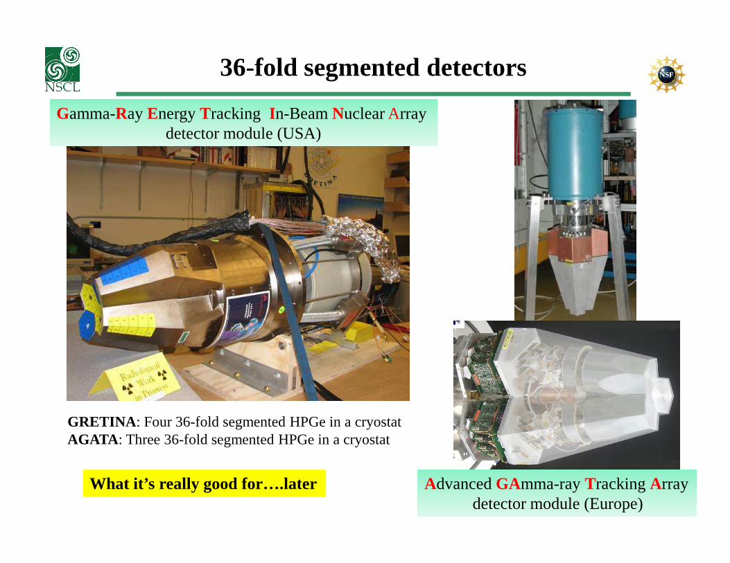
Gamma-Ray Energy Tracking In-Beam Nuclear Arraydetector module (USA)
Advanced GAmma-ray Tracking Arraydetector module (Europe)
GRETINA : Four 36-fold segmented HPGe in a cryostatAGATA : Three 36-fold segmented HPGe in a cryostat
What it’s really good for….later
QUIZ
Statement:
“HPGe detectors provide BEST energy resolution for gamma rays”
a) I agree.b) I don’t agree!
QUIZ
Statement:
“HPGe detectors provide BEST energy resolution for gamma rays”
a) I agree. (i.e “I believe in Poisson statistics”)b) I don’t agree! (i.e. “I believe I-Yang”)

Look beyond the rim of …
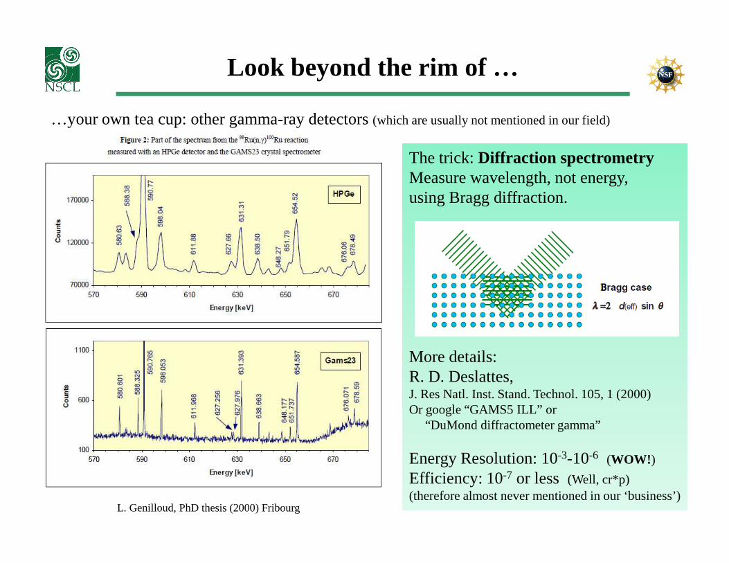
…your own tea cup: other gamma-ray detectors (which are usually not mentioned in our field)
L. Genilloud, PhD thesis (2000) Fribourg
FWHM < 500eV !How is that possible !?!
Look beyond the rim of …
…your own tea cup: other gamma-ray detectors (which are usually not mentioned in our field)
The trick: Diffraction spectrometryMeasure wavelength, not energy,using Bragg diffraction.
L. Genilloud, PhD thesis (2000) Fribourg
More details:R. D. Deslattes, J. Res Natl. Inst. Stand. Technol. 105, 1 (2000)Or google “GAMS5 ILL” or
“DuMond diffractometer gamma”
Energy Resolution: 10-3-10-6 (WOW! )
Efficiency: 10-7 or less (Well, cr*p)(therefore almost never mentioned in our ‘business’)
Gamma-ray spectrometers
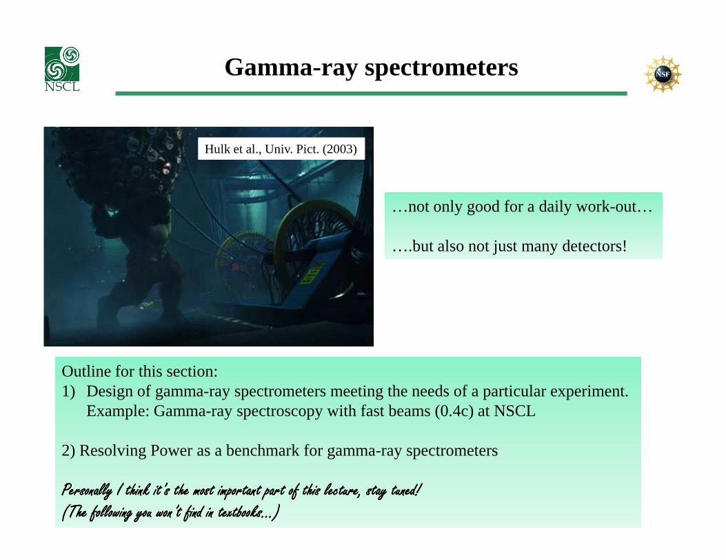
Hulk et al., Univ. Pict. (2003)
…not only good for a daily work-out…
….but also not just many detectors!
Outline for this section:1) Design of gamma-ray spectrometers meeting the needs of a particular experiment.
Example: Gamma-ray spectroscopy with fast beams (0.4c) at NSCL
2) Resolving Power as a benchmark for gamma-ray spectrometers
Personally I think it’s the most important part of this lecture, stay tuned!Personally I think it’s the most important part of this lecture, stay tuned!Personally I think it’s the most important part of this lecture, stay tuned!Personally I think it’s the most important part of this lecture, stay tuned!(The following you won’t find in textbooks…) (The following you won’t find in textbooks…) (The following you won’t find in textbooks…) (The following you won’t find in textbooks…)
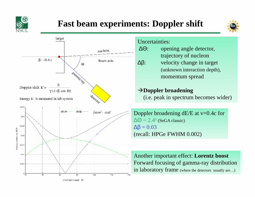
Fast beam experiments: Doppler shift
Uncertainties:∆Θ: opening angle detector,
trajectory of nucleon ∆β: velocity change in target
(unknown interaction depth),momentum spread
�Doppler broadening (i.e. peak in spectrum becomes wider)(i.e. peak in spectrum becomes wider)
Doppler broadening dE/E at v=0.4c for∆Θ = 2.4o (SeGA classic)
∆β = 0.03(recall: HPGe FWHM 0.002)
Another important effect:Lorentz boostForward focusing of gamma-ray distributionin laboratory frame (where the detectors usually are…)

Segmented Germanium Array
SeGA in ‘classic’ configurationo 32-fold segmented HPGe detectorso 10 detectors at 90o, 8 at 37o
o In-beam FWHM 2-3%o In-beam ε 2.5% at 1 MeVo P/T 0.2
beam 0.4c
24Mg
γ spectrum of 24Mg produced in fragmentationreaction of 36Ar on Be. Remember, dE/E=0.2% for Ge

CAESium iodide ARray
� CsI(Na)� 48 3”x 3”x 3” crystals� 144 2”x 2”x 4” crystals� Solid angle coverage 95%� In-beam FWHM: 10% (SeGA: 2-3%)
� Efficiency 35% at 1MeV (SeGA: 2.5%)
“Gain efficiency, pay with resolution”….
FWHM 9.5%
24Mg
…good deal or not? How do we benchmark efficiency vs. resolution?
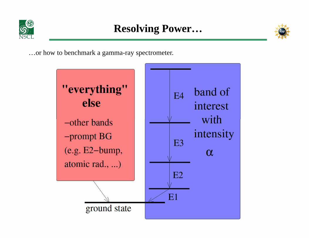
Resolving Power…
…or how to benchmark a gamma-ray spectrometer.
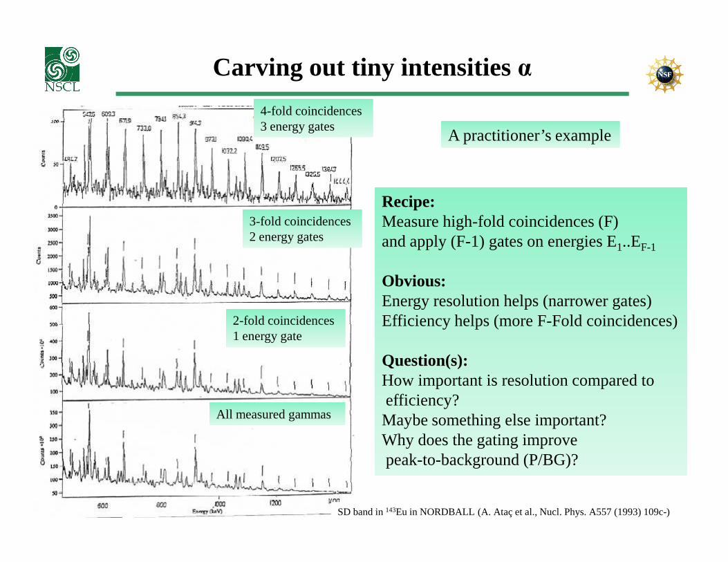
Carving out tiny intensities α
4-fold coincidences 3 energy gates
3-fold coincidences 2 energy gates
Recipe:Measure high-fold coincidences (F)and apply (F-1) gates on energies E1..EF-1
Obvious:
A practitioner’s example
SD band in 143Eu in NORDBALL (A. Ataç et al., Nucl. Phys. A557 (1993) 109c-)
2-fold coincidences 1 energy gate
All measured gammas
Obvious:Energy resolution helps (narrower gates)Efficiency helps (more F-Fold coincidences)
Question(s):How important is resolution compared toefficiency? Maybe something else important?Why does the gating improve peak-to-background (P/BG)?
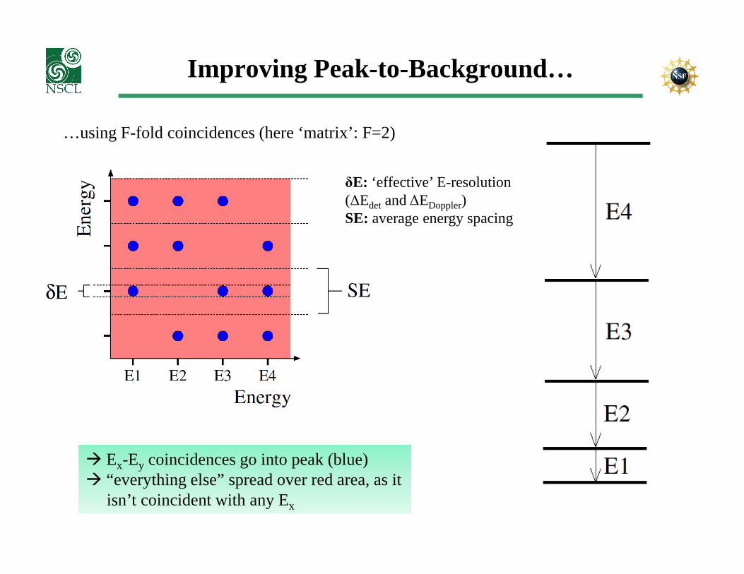
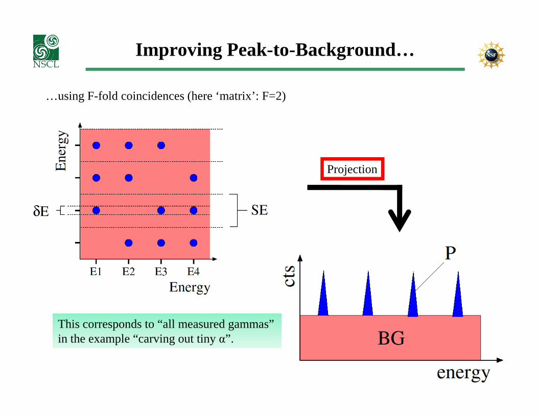
Improving Peak-to-Background…
…using F-fold coincidences (here ‘matrix’: F=2)
δE: ‘effective’ E-resolution(∆Edet and ∆EDoppler)SE: average energy spacing
� Ex-Ey coincidences go into peak (blue)� “everything else” spread over red area, as it
isn’t coincident with any Ex
Improving Peak-to-Background…
…using F-fold coincidences (here ‘matrix’: F=2)
Projection
This corresponds to “all measured gammas”in the example “carving out tiny α”.

Improving Peak-to-Background…
…using F-fold coincidences (‘matrix’: F=2)
Cut along SE
No improvement in P/BG as peak andBG intensities are reduced equally!

Improving Peak-to-Background…
…using F-fold coincidences (‘matrix’: F=2)
Cut along δE
Improvement of P/BG by factor SE/δE !!!
BTW: Of course we would create a cut spectrum for each Ex and sum them up. This improvesstatistics, BUT NOT P/BG.
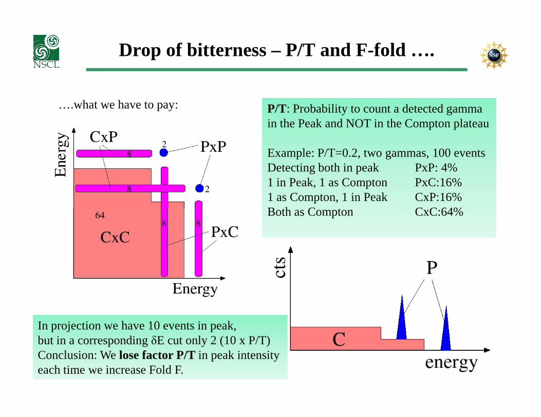
Drop of bitterness – P/T and F-fold ….
….what we have to pay: P/T: Probability to count a detected gammain the Peak and NOT in the Compton plateau
Example: P/T=0.2, two gammas, 100 eventsDetecting both in peak PxP: 4%1 in Peak, 1 as Compton PxC:16%1 as Compton, 1 in Peak CxP:16%Both as Compton CxC:64%Both as Compton CxC:64%
In projection we have 10 events in peak,but in a corresponding δE cut only 2 (10 x P/T)Conclusion: We lose factor P/T in peak intensityeach time we increase Fold F.
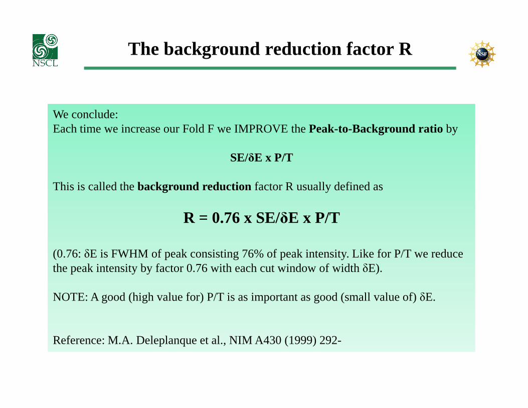
The background reduction factor R
We conclude: Each time we increase our Fold F we IMPROVE the Peak-to-Background ratio by
SE/δE x P/T
This is called the background reduction factor R usually defined as
R = 0.76 x SE/δE x P/T
(0.76: δE is FWHM of peak consisting 76% of peak intensity. Like for P/T we reduce the peak intensity by factor 0.76 with each cut window of width δE).
NOTE: A good (high value for) P/T is as important as good (small value of) δE.
Reference: M.A. Deleplanque et al., NIM A430 (1999) 292-
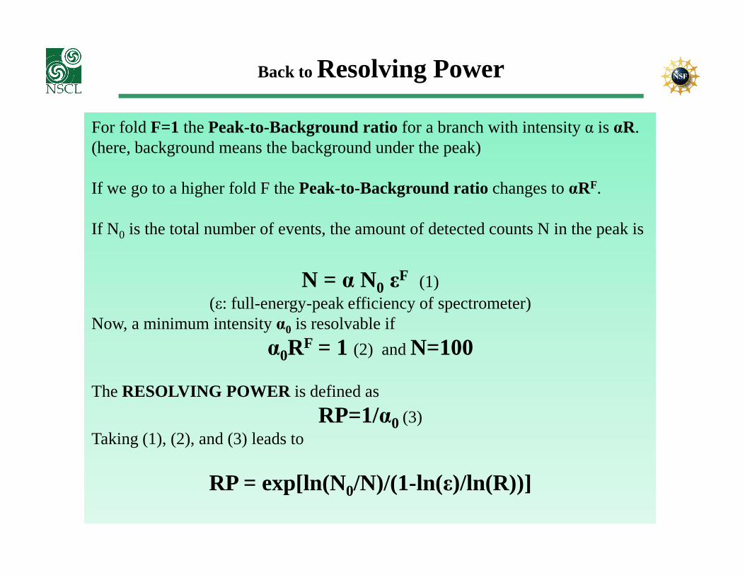
Back to Resolving Power
For fold F=1 the Peak-to-Background ratio for a branch with intensity α is αR.(here, background means the background under the peak)
If we go to a higher fold F the Peak-to-Background ratio changes to αRF.
If N0 is the total number of events, the amount of detected counts N in the peak is
N = α N0 εF (1)N = α N0 ε (1)(ε: full-energy-peak efficiency of spectrometer)
Now, a minimum intensity α0 is resolvable if
α0RF = 1 (2) and N=100
The RESOLVING POWER is defined as
RP=1/α0 (3)Taking (1), (2), and (3) leads to
RP = exp[ln(N0/N)/(1-ln(ε)/ln(R))]
Resolving Power….
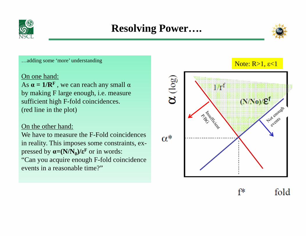
…adding some ‘more’ understanding
On one hand:As α = 1/RF , we can reach any small αby making F large enough, i.e. measuresufficient high F-fold coincidences.(red line in the plot)
Note: R>1, ε<1
On the other hand:We have to measure the F-Fold coincidencesin reality. This imposes some constraints, ex-pressed by α=(N/N0)/εF or in words: “Can you acquire enough F-fold coincidenceevents in a reasonable time?”

RP applied to SeGA and CAESAR
1MeV gamma ray: SeGA: δE= 25keV, P/T=0.22, ε=0.025 CAESAR: δE=100keV, P/T=0.40, ε=0.35
Average line separation SE vs. Resolving Power RP for N0=10.000
RP
Conclusion from RP: For low line density (SE large) CAESAR is superior to SeGA. If line density increases (SE small) SeGA beats CAESAR.[Don’t believe actually the quantitative value of SE = 450keV (!)]
SE[keV]
Back to the Future….the nineties
BGO Suppressor Plug
Detector Electronics
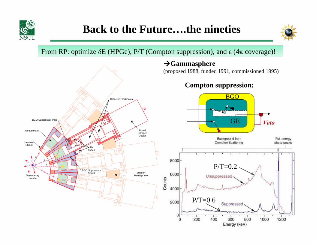
From RP: optimize δE (HPGe), P/T (Compton suppression), and ε (4π coverage)!
����Gammasphere (proposed 1988, funded 1991, commissioned 1995)
BGO
GE
Compton suppression:
γγ
γ
Ge Detector
BGO SuppressorShield
LiquidNitrogenDewar
HevimetShield
SupportHemisphere
PMTubes
Gamma-raySource
GE
P/T=0.2
P/T=0.6
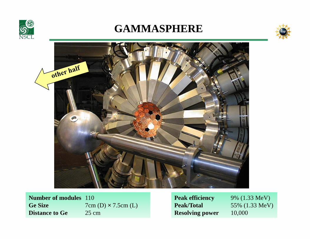
GAMMASPHERE
Number of modules 110Ge Size 7cm (D) × 7.5cm (L)Distance to Ge 25 cm
Peak efficiency 9% (1.33 MeV)Peak/Total 55% (1.33 MeV)Resolving power 10,000

Better instruments – better results
“Spectroscopic history” of 156Dy
6 Compton-suppressed HPGe6 Compton-suppressed HPGe

Spectrometers beyond GAMMASPHERE
As the 36-fold segmented GRETINA/AGATAdetectors do!

Gamma-ray tracking
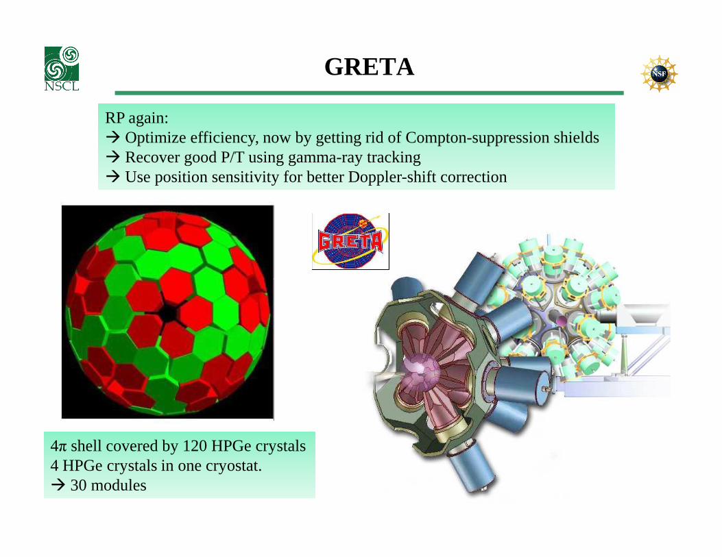
GRETA
RP again: � Optimize efficiency, now by getting rid of Compton-suppression shields � Recover good P/T using gamma-ray tracking� Use position sensitivity for better Doppler-shift correction
4π shell covered by 120 HPGe crystals4 HPGe crystals in one cryostat.� 30 modules
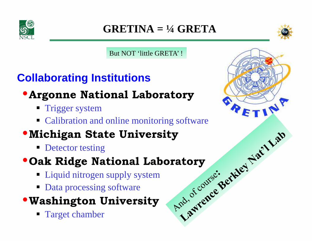
GRETINA = ¼ GRETA
Collaborating Institutions
•Argonne National Laboratory� Trigger system� Calibration and online monitoring software
But NOT ‘little GRETA’ !
� Calibration and online monitoring software
•Michigan State University� Detector testing
•Oak Ridge National Laboratory� Liquid nitrogen supply system� Data processing software
•Washington University� Target chamber
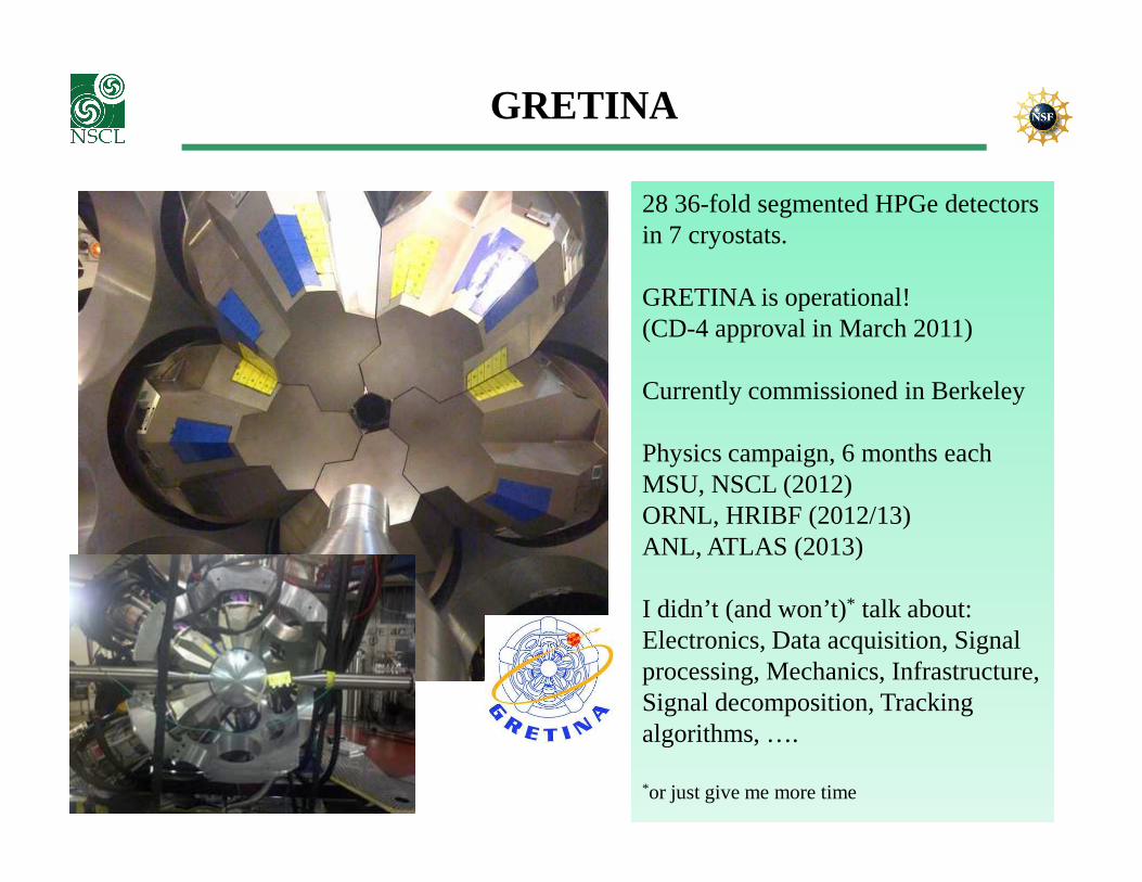
GRETINA
28 36-fold segmented HPGe detectorsin 7 cryostats.
GRETINA is operational!(CD-4 approval in March 2011)
Currently commissioned in Berkeley
Physics campaign, 6 months eachPhysics campaign, 6 months eachMSU, NSCL (2012)ORNL, HRIBF (2012/13)ANL, ATLAS (2013)
I didn’t (and won’t)* talk about:Electronics, Data acquisition, Signalprocessing, Mechanics, Infrastructure,Signal decomposition, Tracking algorithms, ….
*or just give me more time

Resolving Power again….
…but that’s why we built GRETINA, go for GRETA, and Europe does AGATA.
Summary
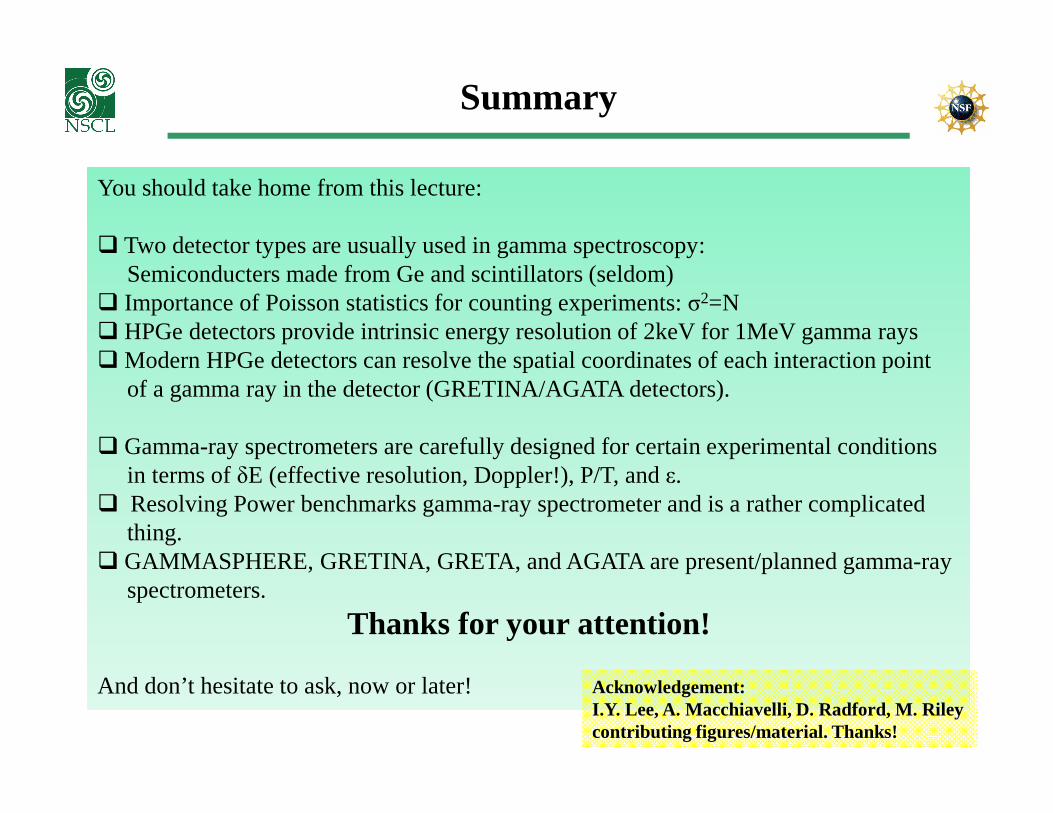
You should take home from this lecture:
� Two detector types are usually used in gamma spectroscopy: Semiconducters made from Ge and scintillators (seldom)
� Importance of Poisson statistics for counting experiments: σ2=N� HPGe detectors provide intrinsic energy resolution of 2keV for 1MeV gamma rays� Modern HPGe detectors can resolve the spatial coordinates of each interaction point
of a gamma ray in the detector (GRETINA/AGATA detectors).
� Gamma-ray spectrometers are carefully designed for certain experimental conditionsin terms of δE (effective resolution, Doppler!), P/T, and ε.
� Resolving Power benchmarks gamma-ray spectrometer and is a rather complicatedthing.
� GAMMASPHERE, GRETINA, GRETA, and AGATA are present/planned gamma-rayspectrometers.
Thanks for your attention!
And don’t hesitate to ask, now or later! Acknowledgement:I.Y. Lee, A. Macchiavelli, D. Radford, M. Rileycontributing figures/material. Thanks!


![TERRESTRIAL GAMMA-RAY FLASHES · the satellite-detected gamma rays. 4. Gamma Ray Survival From Thunderstorm to Satellite [20] The interaction of gamma rays with atmospheric air and](https://static.fdocuments.in/doc/165x107/5ca8857e88c993e47d8bc64f/terrestrial-gamma-ray-flashes-the-satellite-detected-gamma-rays-4-gamma-ray.jpg)