NEED A-935 RODApdf.lowes.com/installationguides/805806175873_install.pdfQCI0274 REV. 1 Page 1...
11
QCI0274 REV. 1 Page 1 Certified 10/01/10 A-935 RODA WALL MOUNT HINGES FRAMELESS DOOR / PANEL INSTALLATION INSTRUCTIONS CELESTA NEED INSTALLATION HELP? Call 1-800-45-BASCO (452-2726) Monday - Friday 8:00 A.M. - 4:30 P.M. Eastern Time
Transcript of NEED A-935 RODApdf.lowes.com/installationguides/805806175873_install.pdfQCI0274 REV. 1 Page 1...
QCI0274 REV. 1 Page 1 Certified 10/01/10
A-935 RODA WALL MOUNT HINGES
FRAMELESS DOOR / PANEL
INSTALLATION INSTRUCTIONS
CELESTA
NEED INSTALLATION HELP? Call 1-800-45-BASCO (452-2726)
Monday - Friday 8:00 A.M. - 4:30 P.M.
Eastern Time

QCI0274 REV. 1 Page 2 Certified 10/01/10
935 Roda Parts List with wall mount hinges
*Quantities may vary
ITEM NO. Part # DESCRIPTION QTY
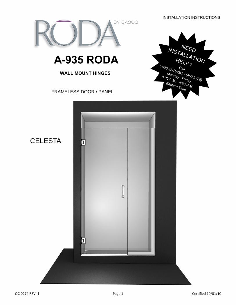
1 PD-GLASS GLASS DOOR 1
2 PN-GLASS FIXED GLASS PANEL 1
3 HG1J-000BS WALL MOUNT HINGE 2
4 SC925 HORIZONTAL U-CHANNEL 1
5 SC925 VERTICAL U-CHANNEL 1
6 PU1D-8BH PULL HANDLE 1
7 SCV920 DRIP VINYL 1
8 SCV913 STRIKE VINYL 1
9 CELESTAPP #8 X 1 1/2 TRUSS HEAD SCREW 4
10 CELESTAPP PLASTIC WALL ANCHOR 4
QCI0274 REV. 1 Page 3 Certified 10/01/10
935 Roda Exploded View with wall mount hinges
1
3
6
2
5
4
7 9
10
9
3
10

QCI0274 REV. 1 Page 4 Certified 10/01/10
Tools:
To install your Roda Shower Enclosure, you will need the following:
- Pencil - Low Tack Masking Tape - Tape Measure - 4’ & 6’ Levels - #2 Phillips Screwdriver - Drill - 3/16” - 1/4” Drill Bit
- Hack Saw - Caulk (Clear Silicone Recommended) - Caulk Gun - Suction Cups - Center Punch (if drilling into tile) - Files
Installation Notes:
This unit is best installed by two people. Cover the drain with tape prior to installation to prevent loss of small parts. Unpack your unit carefully and inspect for freight damage. Lay out and identify all parts using the instruction sheet as a reference. Before discarding the carton, check to see that no small hard-ware parts have fallen to the bottom of the box. If any parts are damaged or missing, refer to the description noted in the instructions when contacting your dealer for replacements. Handle the glass panels carefully and protect the edges. Safety tempered glass is very resistant to breakage, but the sharp corners of the panels can damage tile and flooring surfaces. Also, the glass can break if unequal pressure is applied during installation. Please wear safety glasses whenever drilling or cutting. When drilling holes in ceramic tile or mar-ble, use a center punch and hammer to carefully break the glazed surface to prevent skidding when drilling.
Maintenance:
Two primary materials are used to manufacture your new Basco shower enclosure: tempered glass and anodized aluminum. To assure a long lasting finish on the enclosure, wipe it down with a towel after each use. For occasional, more concentrated cleaning efforts, we find that Lysol Non-Abrasive Bathroom Cleaner works extremely well. Be sure that any over spray falling on the aluminum frame is rinsed thoroughly and dried. Many over-the-counter cleaners, if applied to the aluminum and left on, will harm the metal finish and cause permanent damage even though their directions indicate safe use on shower doors. Never use a scouring agent to clean the aluminum.
NOTE: Tempered glass cannot be cut.
QCI0274 REV. 1 Page 5 Certified 10/01/10
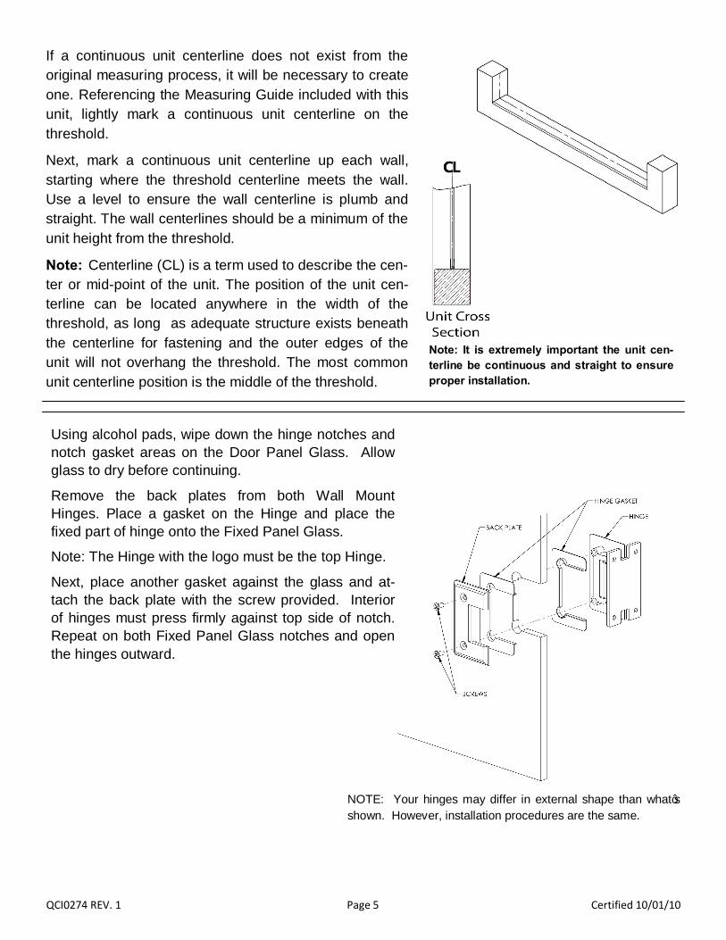
If a continuous unit centerline does not exist from the original measuring process, it will be necessary to create one. Referencing the Measuring Guide included with this unit, lightly mark a continuous unit centerline on the threshold.
Next, mark a continuous unit centerline up each wall, starting where the threshold centerline meets the wall. Use a level to ensure the wall centerline is plumb and straight. The wall centerlines should be a minimum of the unit height from the threshold.
Note: Centerline (CL) is a term used to describe the cen-ter or mid-point of the unit. The position of the unit cen-terline can be located anywhere in the width of the threshold, as long as adequate structure exists beneath the centerline for fastening and the outer edges of the unit will not overhang the threshold. The most common unit centerline position is the middle of the threshold.
Note: It is extremely important the unit cen-terline be continuous and straight to ensure proper installation.
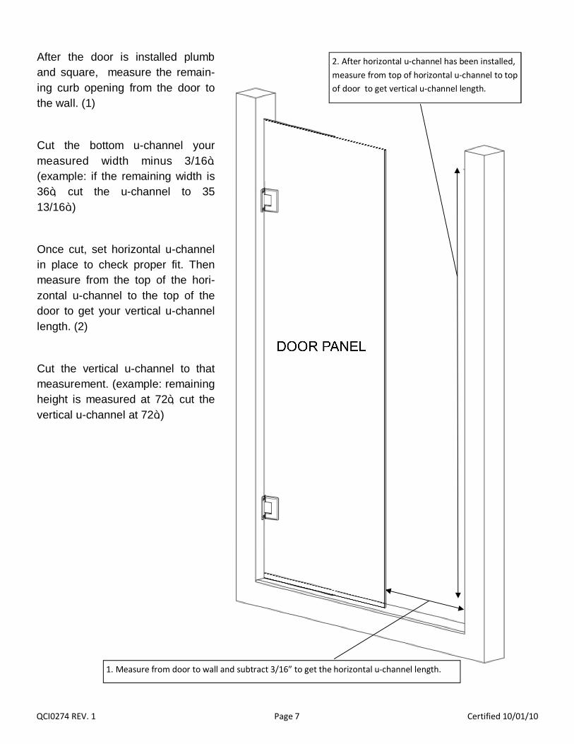
Using alcohol pads, wipe down the hinge notches and notch gasket areas on the Door Panel Glass. Allow glass to dry before continuing.
Remove the back plates from both Wall Mount Hinges. Place a gasket on the Hinge and place the fixed part of hinge onto the Fixed Panel Glass.
Note: The Hinge with the logo must be the top Hinge.
Next, place another gasket against the glass and at-tach the back plate with the screw provided. Interior of hinges must press firmly against top side of notch. Repeat on both Fixed Panel Glass notches and open the hinges outward.
NOTE: Your hinges may differ in external shape than what’s shown. However, installation procedures are the same.

QCI0274 REV. 1 Page 6 Certified 10/01/10
Place two 7/16” shims on the curb or threshold. These shims must remain in place throughout the installation process.
One person must position themselves inside the shower, and have an assistant on the outside. Together, lift the Door Panel Glass into the opening and set the panel on the shims. Align the panel on the threshold and wall centerlines.
Once the door is positioned, set a 1/4” clearance between the Door Panel Glass and the wall. The door must be plumb to al-low the hinge pins to align with one another.
With the door panel aligned and plumbed, mark the mounting hole locations for both wall mount hinges.
Remove the Door Panel Glass from the opening. Use the marks as a guide and drill 3/16” holes through the tile and/or backing material. Do not drill through the wood backing.
Drill a 1/8” pilot hole into the stud to allow the screw to seat properly. Place a small amount of sili-cone sealant into each hole.
Carefully move the Door Panel Glass back into the opening. Align the hinges with pre-drilled holes and carefully secure with the provided screws.
If interference exists, hinges can be loosened to adjust gaps. The gap should be 3/16” on each side of the door; 7/16” between the door and threshold at the highest point; door and panel glass flush at top. Re-tighten all screws after final adjustment. If a hinge is scratched in the tightening process touch up paint may be used.
Note: The screws may begin to “creak” when fully tightened.
Carefully and slowly close the door and inspect the door panel gaps for interference.
Do not force door closed.
Use Caution to prevent the drill chuck from contacting the hinge.
Proper structural backing is required for installation of any door panel. An example of proper backing is two (2) 2x4 studs back to back.
Failure to ensure proper backing may lead to damage or per-sonal injury from improper installation
To prevent the door from sagging after final gap adjustment the hinge maybe shimmed to prevent movement.
Remove one back plate at a time and fill gaps (marked in the figure to the left) surrounding hinge with shims supplied in parts pack. Make sure to shim both hinges and use combina-tion of shim thicknesses to fill entire gap.
QCI0274 REV. 1 Page 7 Certified 10/01/10
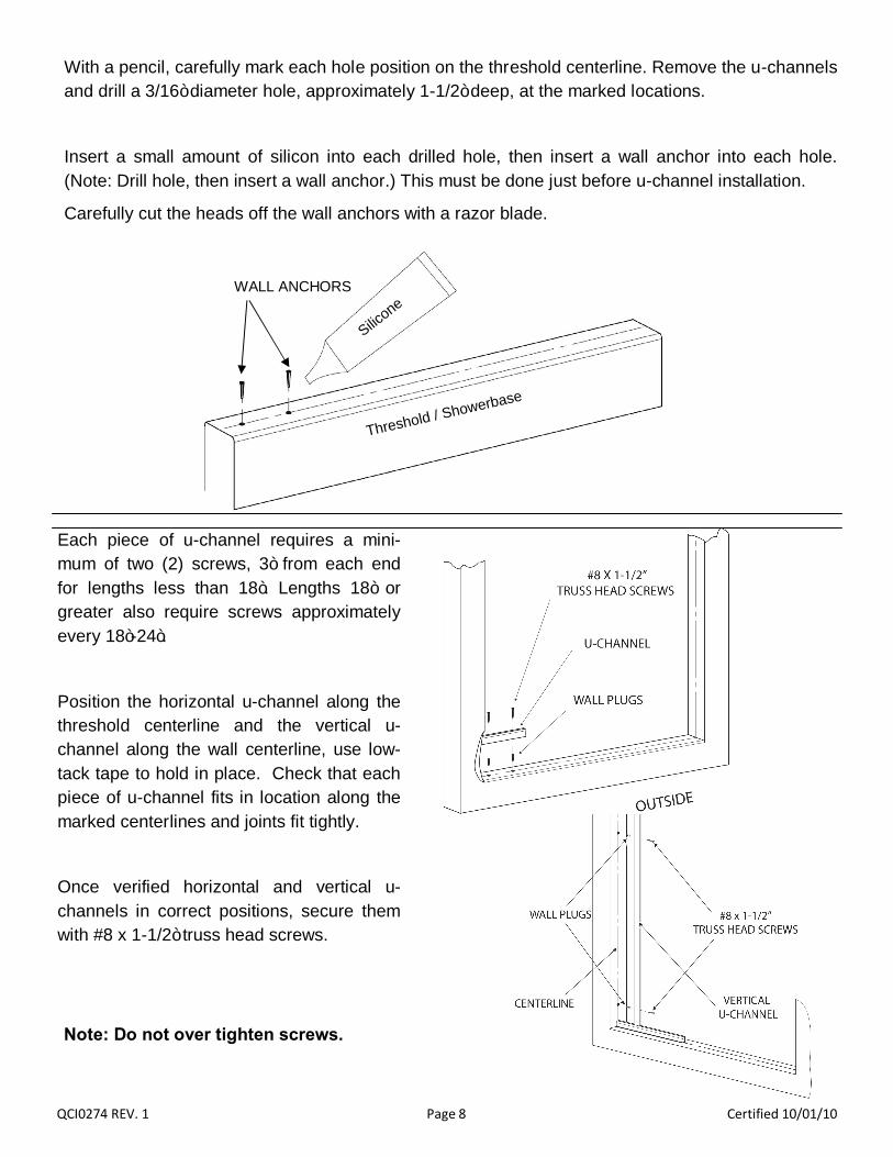
After the door is installed plumb and square, measure the remain-ing curb opening from the door to the wall. (1)
Cut the bottom u-channel your measured width minus 3/16”. (example: if the remaining width is 36”, cut the u-channel to 35 13/16”.)
Once cut, set horizontal u-channel in place to check proper fit. Then measure from the top of the hori-zontal u-channel to the top of the door to get your vertical u-channel length. (2)
Cut the vertical u-channel to that measurement. (example: remaining height is measured at 72”, cut the vertical u-channel at 72”.)
1. Measure from door to wall and subtract 3/16” to get the horizontal u-channel length.
2. After horizontal u-channel has been installed, measure from top of horizontal u-channel to top of door to get vertical u-channel length.
QCI0274 REV. 1 Page 8 Certified 10/01/10
Each piece of u-channel requires a mini-mum of two (2) screws, 3” from each end for lengths less than 18”. Lengths 18” or greater also require screws approximately every 18”-24”.
Position the horizontal u-channel along the threshold centerline and the vertical u-channel along the wall centerline, use low-tack tape to hold in place. Check that each piece of u-channel fits in location along the marked centerlines and joints fit tightly.
Once verified horizontal and vertical u-channels in correct positions, secure them with #8 x 1-1/2” truss head screws.
With a pencil, carefully mark each hole position on the threshold centerline. Remove the u-channels and drill a 3/16” diameter hole, approximately 1-1/2” deep, at the marked locations.
Insert a small amount of silicon into each drilled hole, then insert a wall anchor into each hole. (Note: Drill hole, then insert a wall anchor.) This must be done just before u-channel installation.
Carefully cut the heads off the wall anchors with a razor blade.
WALL ANCHORS
Threshold / Showerbase
Silicone
Note: Do not over tighten screws.
QCI0274 REV. 1 Page 9 Certified 10/01/10
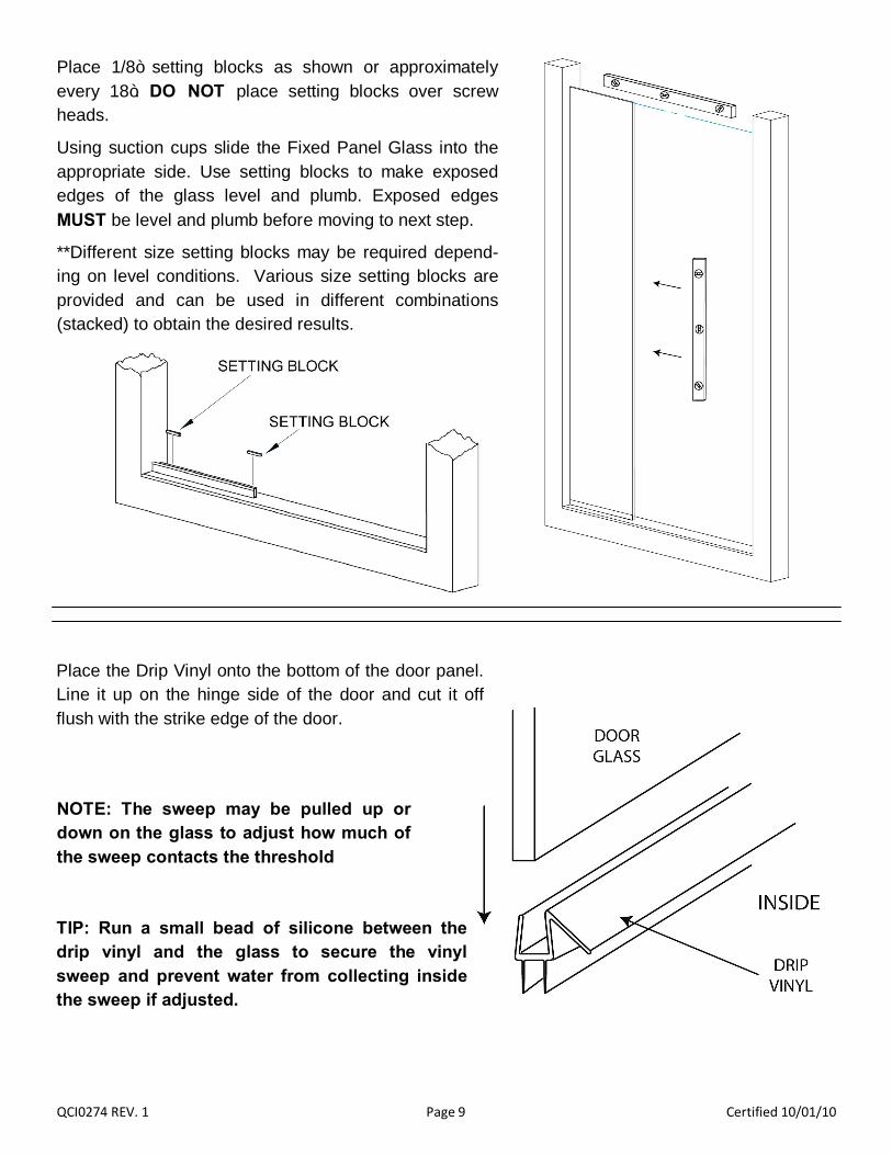
Place 1/8” setting blocks as shown or approximately every 18”. DO NOT place setting blocks over screw heads.
Using suction cups slide the Fixed Panel Glass into the appropriate side. Use setting blocks to make exposed edges of the glass level and plumb. Exposed edges MUST be level and plumb before moving to next step.
**Different size setting blocks may be required depend-ing on level conditions. Various size setting blocks are provided and can be used in different combinations (stacked) to obtain the desired results.
Place the Drip Vinyl onto the bottom of the door panel. Line it up on the hinge side of the door and cut it off flush with the strike edge of the door.
NOTE: The sweep may be pulled up or down on the glass to adjust how much of the sweep contacts the threshold
TIP: Run a small bead of silicone between the drip vinyl and the glass to secure the vinyl sweep and prevent water from collecting inside the sweep if adjusted.
QCI0274 REV. 1 Page 10 Certified 10/01/10
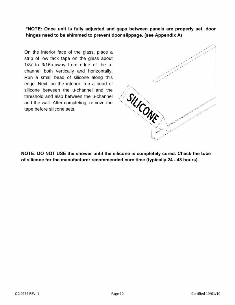
On the interior face of the glass, place a strip of low tack tape on the glass about 1/8” to 3/16” away from edge of the u-channel both vertically and horizontally. Run a small bead of silicone along this edge. Next, on the interior, run a bead of silicone between the u-channel and the threshold and also between the u-channel and the wall. After completing, remove the tape before silicone sets.
NOTE: DO NOT USE the shower until the silicone is completely cured. Check the tube of silicone for the manufacturer recommended cure time (typically 24 - 48 hours).
*NOTE: Once unit is fully adjusted and gaps between panels are properly set, door hinges need to be shimmed to prevent door slippage. (see Appendix A)
QCI0274 REV. 1 Page 11 Certified 10/01/10
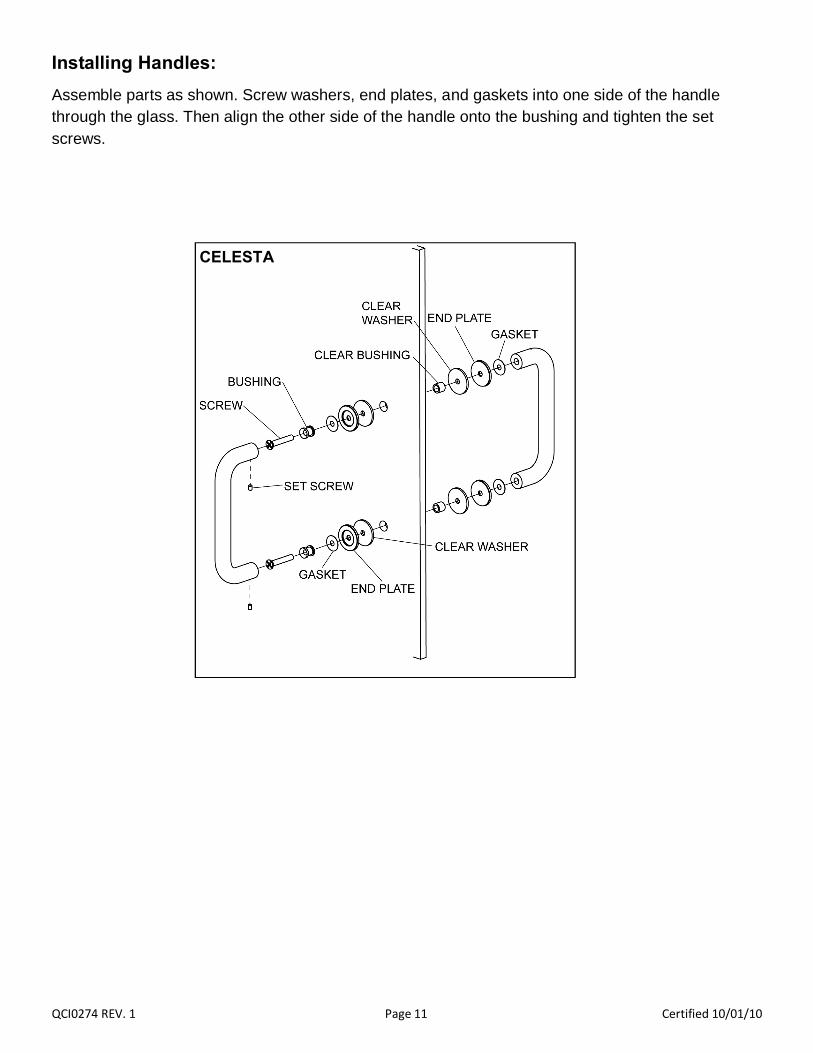
Installing Handles: Assemble parts as shown. Screw washers, end plates, and gaskets into one side of the handle through the glass. Then align the other side of the handle onto the bushing and tighten the set screws.
CELESTA


![EED 935 RODA - pdf.lowes.compdf.lowes.com/installationguides/805806176696_install.pdf · QI0286 13 XX/XX/XXXX í ò Place large Vinyl Seal [15] on Door Panel [2] so that the vinyl](https://static.fdocuments.in/doc/165x107/5ee31d06ad6a402d666d30fc/eed-935-roda-pdflowes-qi0286-13-xxxxxxxx-place-large-vinyl-seal-15.jpg)