NCSX NCSX Planar Coil "ASIPP" Presentation 1 December 8-10, 2005 Michael Kalish NCSX TF and PF...
45
NCSX Planar Coil "ASIPP" Presentation 1 NCSX December 8-10, 2 005 Michael Kalish NCSX TF and PF Coils
-
Upload
margery-baker -
Category
Documents
-
view
215 -
download
0
Transcript of NCSX NCSX Planar Coil "ASIPP" Presentation 1 December 8-10, 2005 Michael Kalish NCSX TF and PF...
NCSX Planar Coil "ASIPP" Presentation 1
NCSX
December 8-10, 2005
Michael Kalish
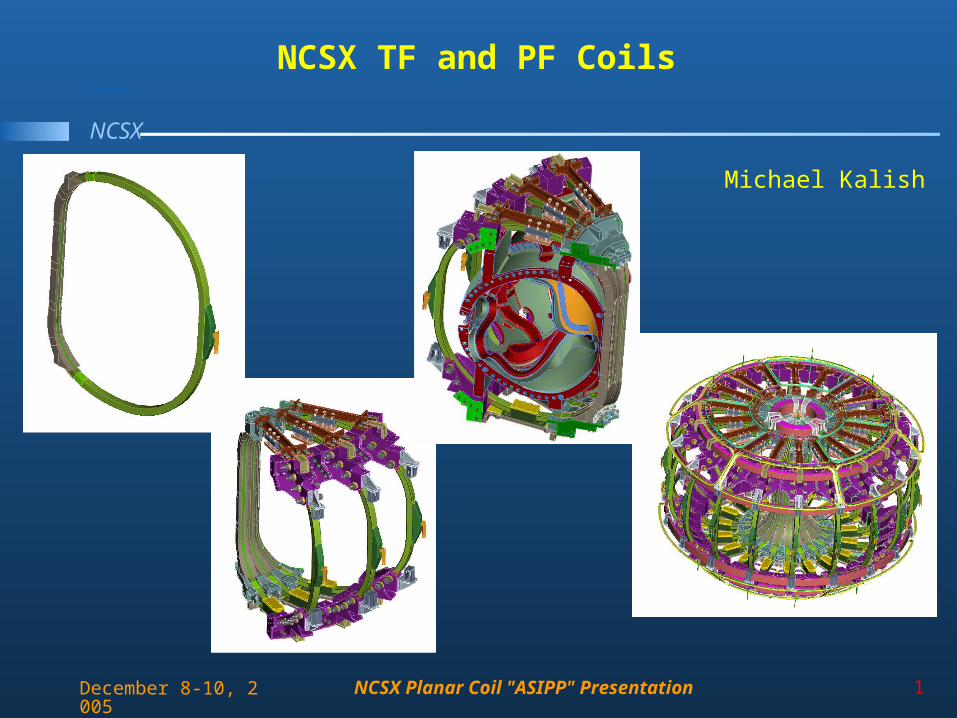
NCSX TF and PF Coils
NCSX Planar Coil "ASIPP" Presentation 2
NCSX
December 8-10, 2005
Outline
• Design– TF Coil Assembly– PF Coils
• Analysis and Test• Fabrication• Topics for Discussion
NCSX Planar Coil "ASIPP" Presentation 3
NCSX
December 8-10, 2005
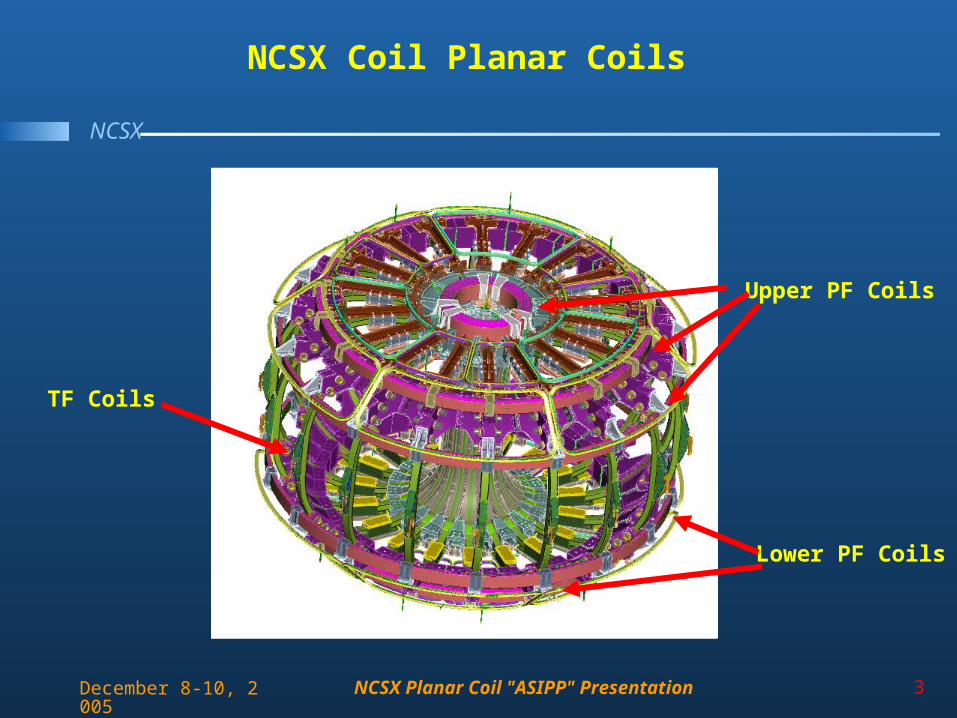
NCSX Coil Planar Coils
TF Coils
Upper PF Coils
Lower PF Coils
NCSX Planar Coil "ASIPP" Presentation 4
NCSX
December 8-10, 2005
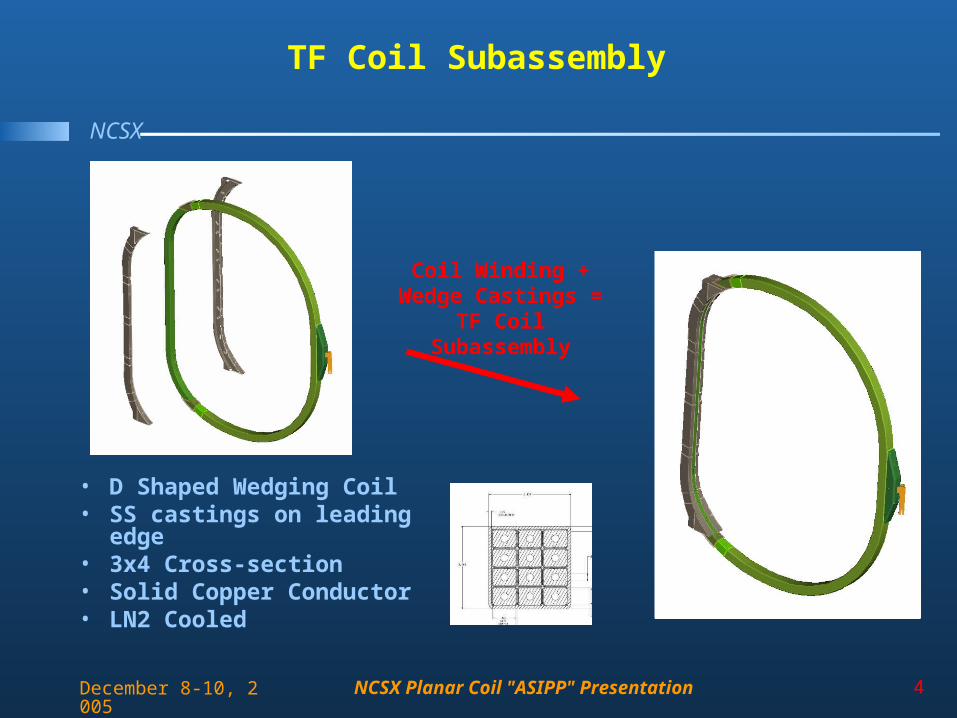
TF Coil Subassembly
• D Shaped Wedging Coil• SS castings on leading edge• 3x4 Cross-section• Solid Copper Conductor• LN2 Cooled
Coil Winding +Wedge Castings =
TF Coil Subassembly
NCSX Planar Coil "ASIPP" Presentation 5
NCSX
December 8-10, 2005
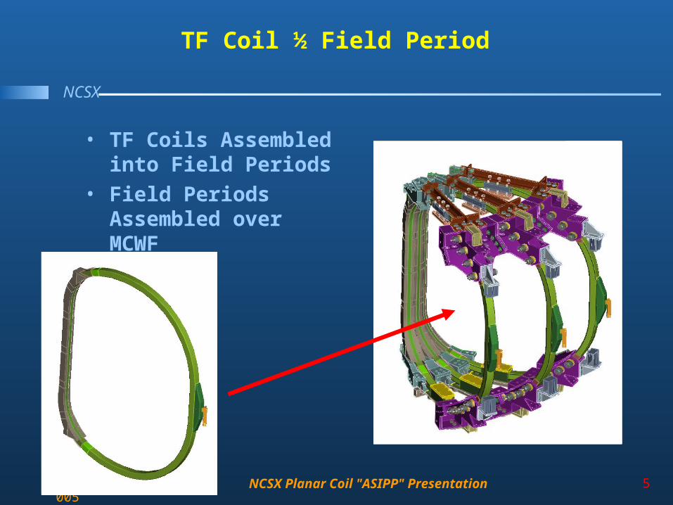
TF Coil ½ Field Period
• TF Coils Assembled into Field Periods
• Field Periods Assembled over MCWF
NCSX Planar Coil "ASIPP" Presentation 6
NCSX
December 8-10, 2005
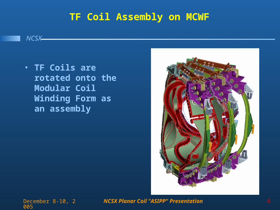
TF Coil Assembly on MCWF
• TF Coils are rotated onto the Modular Coil Winding Form as an assembly
NCSX Planar Coil "ASIPP" Presentation 7
NCSX
December 8-10, 2005
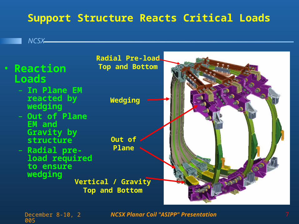
Support Structure Reacts Critical Loads
• Reaction Loads– In Plane EM
reacted by wedging
– Out of Plane EM and Gravity by structure
– Radial pre-load required to ensure wedging
Wedging
Out of Plane
Vertical / GravityTop and Bottom
Radial Pre-loadTop and Bottom
NCSX Planar Coil "ASIPP" Presentation 8
NCSX
December 8-10, 2005
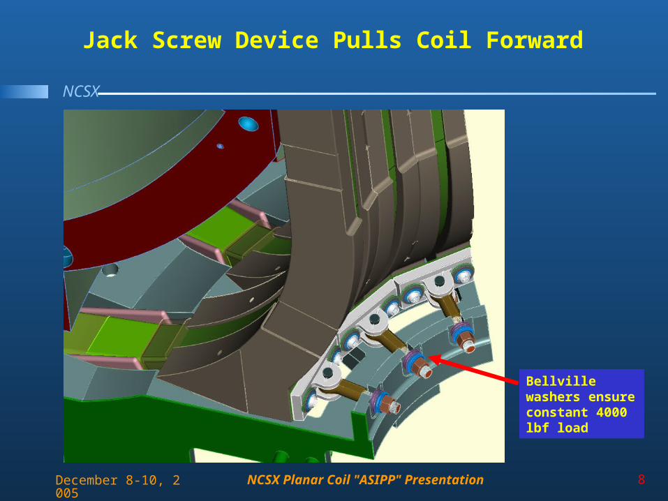
Jack Screw Device Pulls Coil Forward
Bellville washers ensure constant 4000 lbf load
NCSX Planar Coil "ASIPP" Presentation 9
NCSX
December 8-10, 2005
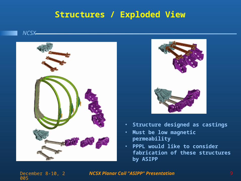
Structures / Exploded View
• Structure designed as castings
• Must be low magnetic permeability
• PPPL would like to consider fabrication of these structures by ASIPP
NCSX Planar Coil "ASIPP" Presentation 10
NCSX
December 8-10, 2005
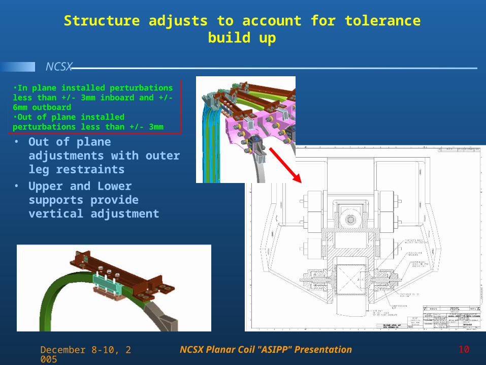
Structure adjusts to account for tolerance build up
• Out of plane adjustments with outer leg restraints
• Upper and Lower supports provide vertical adjustment
•In plane installed perturbations less than +/- 3mm inboard and +/- 6mm outboard•Out of plane installed perturbations less than +/- 3mm
NCSX Planar Coil "ASIPP" Presentation 11
NCSX
December 8-10, 2005
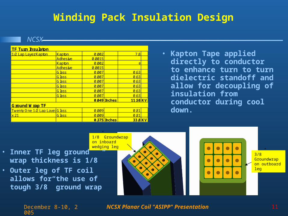
Winding Pack Insulation Design
TF Turn Insulaton1/2 Lap Layer Kapton Kapton 0.002 7.8
Adhesive 0.0015Kapton 0.002 0
Adhesive 0.0015Glass 0.007 0.63Glass 0.007 0.63Glass 0.007 0.63Glass 0.007 0.63Glass 0.007 0.63Glass 0.007 0.63
0.049 Inches 11.58 KV
Ground Wrap TFTwenty One 1/2 Lap Layers Dry GlassGlass 0.009 0.81x 21 Glass 0.009 0.81
0.375 Inches 33.8 KV
3/8” Groundwrap on outboard leg
1/8” Groundwrap on inboard wedging leg
• Kapton Tape applied directly to conductor to enhance turn to turn dielectric standoff and allow for decoupling of insulation from conductor during cool down.
• Inner TF leg ground wrap thickness is 1/8”
• Outer leg of TF coil allows for the use of tough 3/8” ground wrap
NCSX Planar Coil "ASIPP" Presentation 12
NCSX
December 8-10, 2005
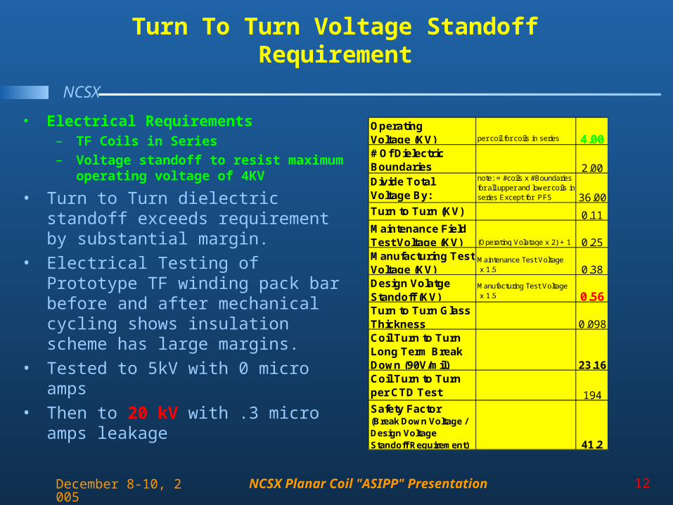
Turn To Turn Voltage Standoff Requirement
Operating Voltage (KV) per coil for coils in series 4.00# Of Dielectric Boundaries 2.00Divide Total Voltage By:
note: = #coils x #Boundaries for all upper and lower coils in series Except for PF5 36.00
Turn to Turn (KV) 0.11Maintenance Field Test Voltage (KV) (Operating Volatage x 2) + 1 0.25Manufacturing Test Voltage (KV)
Maintenance Test Voltage x 1.5 0.38
Design Volatge Standoff (KV)
Manufacturing Test Voltage x 1.5 0.56
Turn to Turn Glass Thickness 0.098Coil Turn to Turn Long Term Break Down (90V/mil) 23.16Coil Turn to Turn per CTD Test (1.9KV/mil)
194Safety Factor(Break Down Voltage / Design Voltage Standoff Requirement) 41.2
• Electrical Requirements– TF Coils in Series
– Voltage standoff to resist maximum operating voltage of 4KV
• Turn to Turn dielectric standoff exceeds requirement by substantial margin.
• Electrical Testing of Prototype TF winding pack bar before and after mechanical cycling shows insulation scheme has large margins.
• Tested to 5kV with 0 micro amps
• Then to 20 kV with .3 micro amps leakage
NCSX Planar Coil "ASIPP" Presentation 13
NCSX
December 8-10, 2005
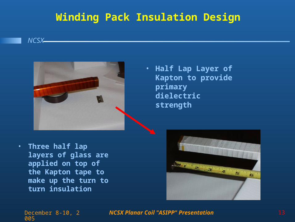
Winding Pack Insulation Design
• Half Lap Layer of Kapton to provide primary dielectric strength
• Three half lap layers of glass are applied on top of the Kapton tape to make up the turn to turn insulation
NCSX Planar Coil "ASIPP" Presentation 14
NCSX
December 8-10, 2005
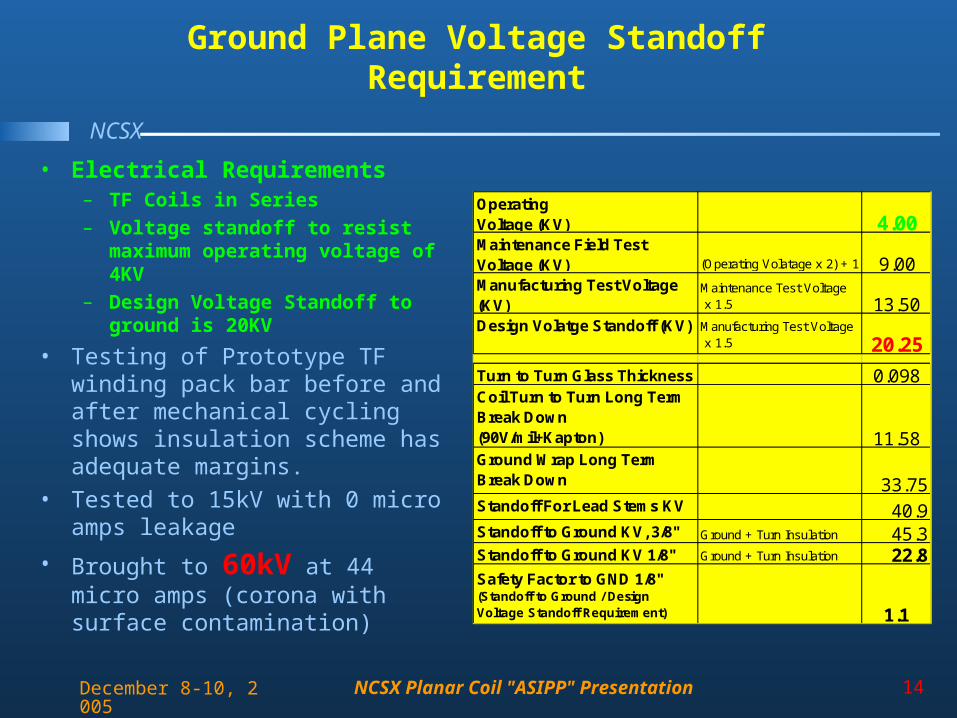
Ground Plane Voltage Standoff Requirement
• Electrical Requirements– TF Coils in Series– Voltage standoff to resist
maximum operating voltage of 4KV
– Design Voltage Standoff to ground is 20KV
• Testing of Prototype TF winding pack bar before and after mechanical cycling shows insulation scheme has adequate margins.
• Tested to 15kV with 0 micro amps leakage
• Brought to 60kV at 44 micro amps (corona with surface contamination)
Operating Voltage (KV) 4.00Maintenance Field Test Voltage (KV) (Operating Volatage x 2) + 1 9.00Manufacturing Test Voltage (KV)
Maintenance Test Voltage x 1.5 13.50
Design Volatge Standoff (KV) Manufacturing Test Voltage x 1.5 20.25
Turn to Turn Glass Thickness 0.098Coil Turn to Turn Long Term Break Down (90V/mil+Kapton) 11.58Ground Wrap Long Term Break Down 33.75Standoff For Lead Stems KV 40.9Standoff to Ground KV, 3/8" Ground + Turn Insulation 45.3Standoff to Ground KV 1/8" Ground + Turn Insulation 22.8Safety Factor to GND 1/8"(Standoff to Ground / Design Voltage Standoff Requirement) 1.1
NCSX Planar Coil "ASIPP" Presentation 15
NCSX
December 8-10, 2005
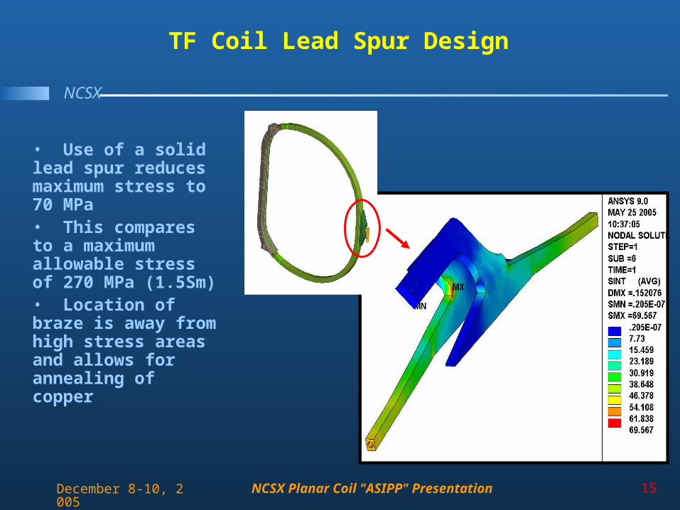
TF Coil Lead Spur Design
• Use of a solid lead spur reduces maximum stress to 70 MPa• This compares to a maximum allowable stress of 270 MPa (1.5Sm)• Location of braze is away from high stress areas and allows for annealing of copper
NCSX Planar Coil "ASIPP" Presentation 16
NCSX
December 8-10, 2005
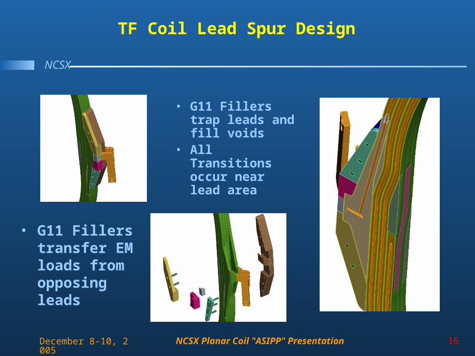
TF Coil Lead Spur Design
• G11 Fillers trap leads and fill voids
• All Transitions occur near lead area
• G11 Fillers transfer EM loads from opposing leads
NCSX Planar Coil "ASIPP" Presentation 17
NCSX
December 8-10, 2005
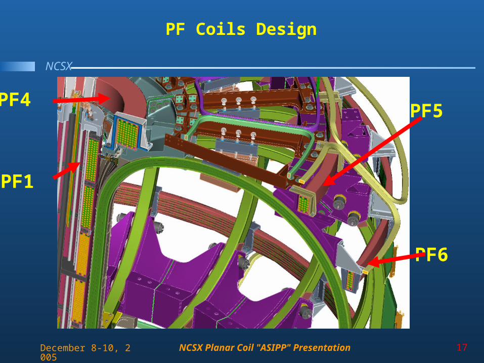
PF Coils Design
PF1
PF4PF5
PF6
NCSX Planar Coil "ASIPP" Presentation 18
NCSX
December 8-10, 2005
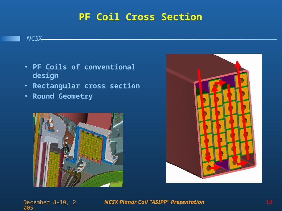
PF Coil Cross Section
• PF Coils of conventional design
• Rectangular cross section
• Round Geometry
NCSX Planar Coil "ASIPP" Presentation 19
NCSX
December 8-10, 2005
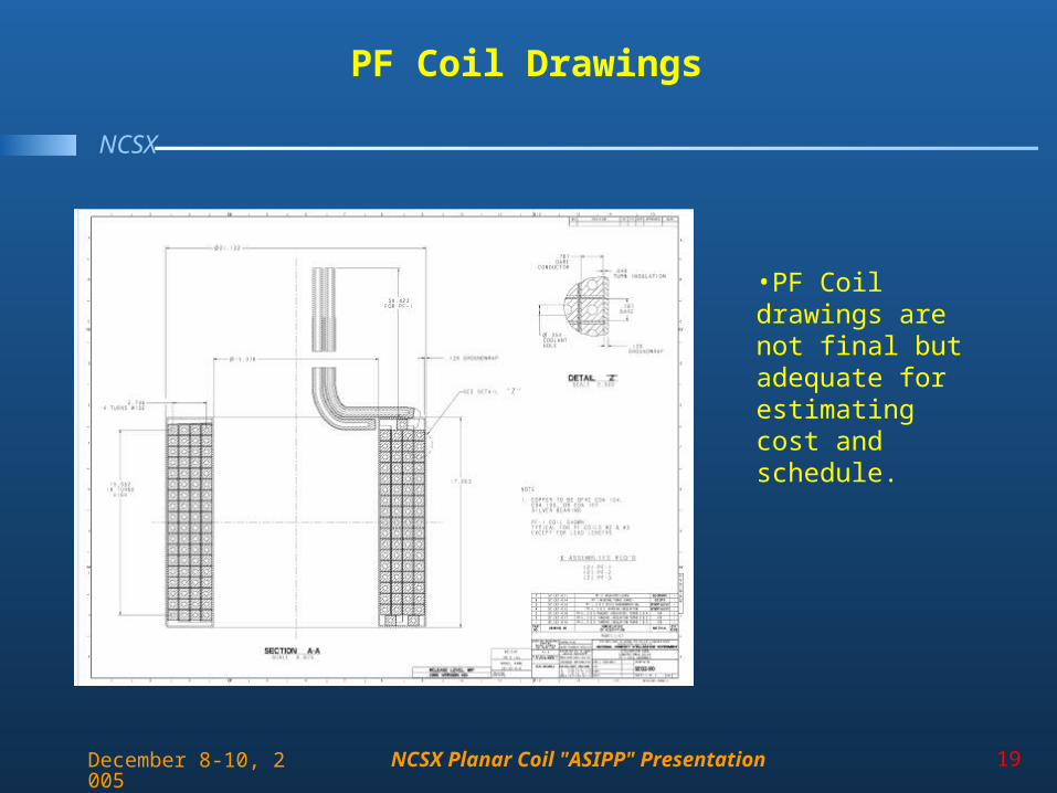
PF Coil Drawings
•PF Coil drawings are not final but adequate for estimating cost and schedule.
NCSX Planar Coil "ASIPP" Presentation 20
NCSX
December 8-10, 2005
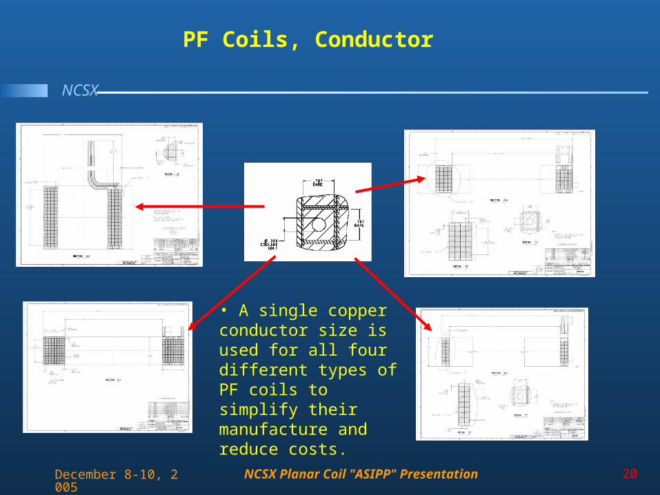
PF Coils, Conductor
• A single copper conductor size is used for all four different types of PF coils to simplify their manufacture and reduce costs.
NCSX Planar Coil "ASIPP" Presentation 21
NCSX
December 8-10, 2005
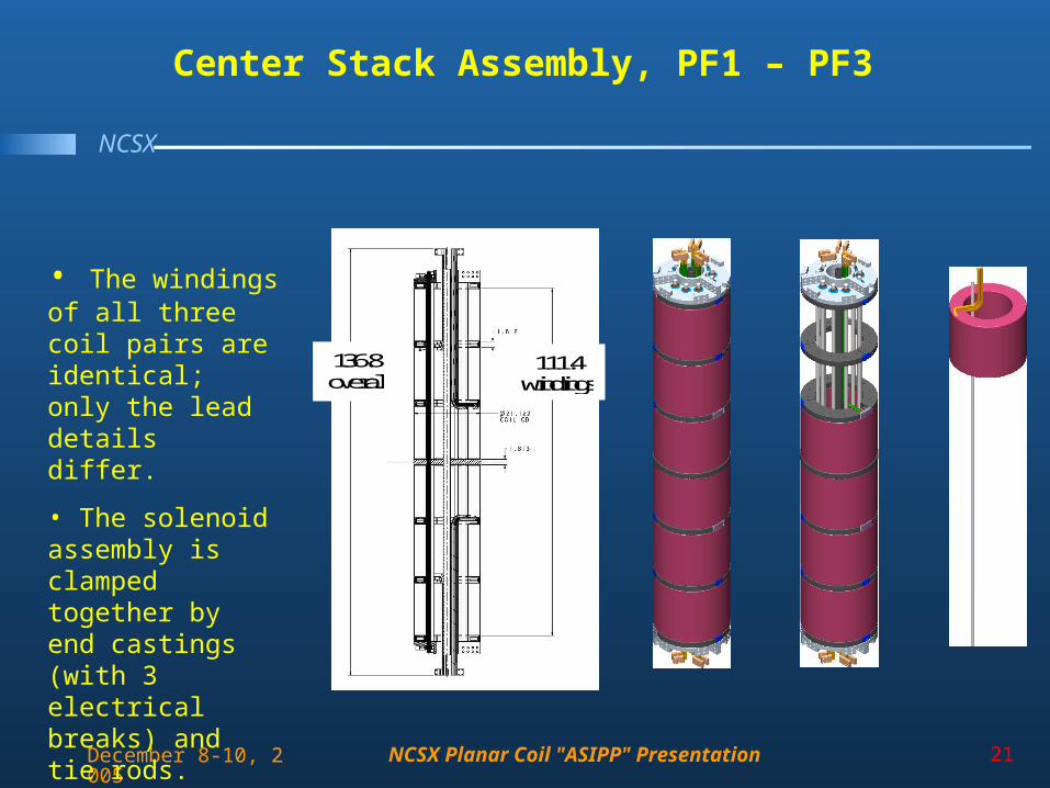
Center Stack Assembly, PF1 – PF3
136.8 overall
111.4 windings
• The windings of all three coil pairs are identical; only the lead details differ.
• The solenoid assembly is clamped together by end castings (with 3 electrical breaks) and tie rods.
NCSX Planar Coil "ASIPP" Presentation 22
NCSX
December 8-10, 2005
Outline
• Design• Analysis and Test• Fabrication• Topics for Discussion
NCSX Planar Coil "ASIPP" Presentation 23
NCSX
December 8-10, 2005
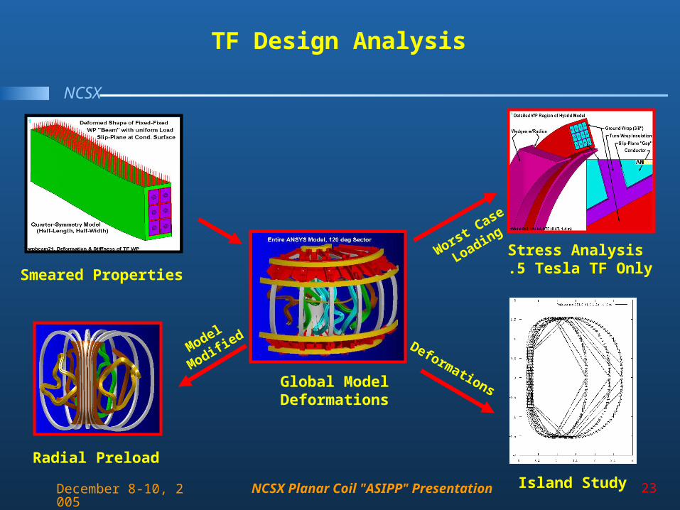
TF Design Analysis
Global ModelDeformations
Smeared Properties
Island Study
Deformations
Worst Case
LoadingStress Analysis .5 Tesla TF Only
Model
Modified
Radial Preload
NCSX Planar Coil "ASIPP" Presentation 24
NCSX
December 8-10, 2005
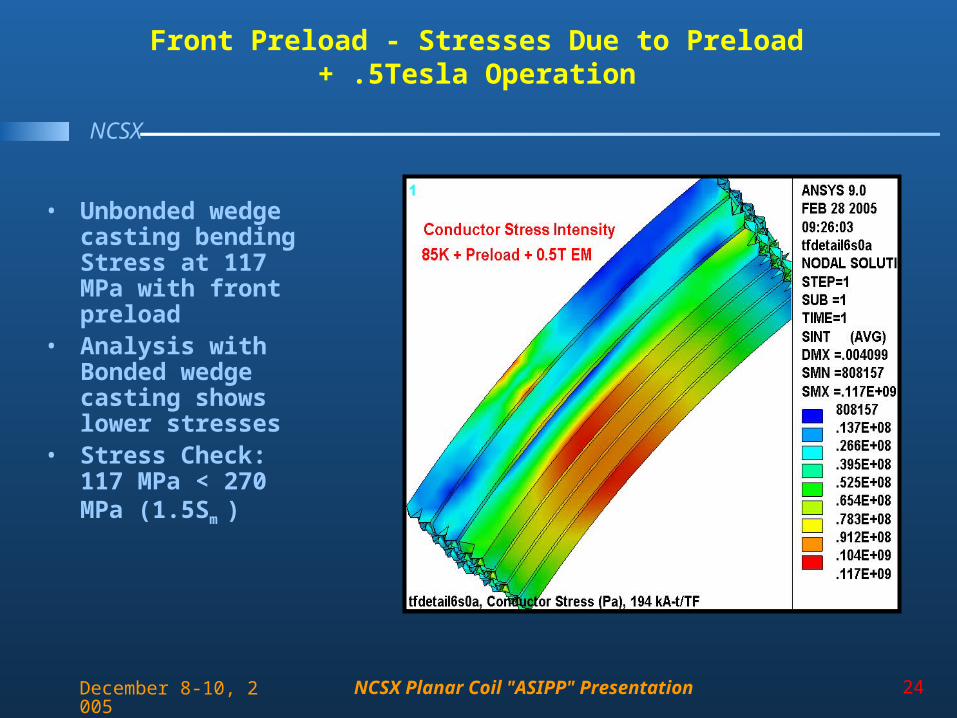
Front Preload - Stresses Due to Preload + .5Tesla Operation
• Unbonded wedge casting bending Stress at 117 MPa with front preload
• Analysis with Bonded wedge casting shows lower stresses
• Stress Check: 117 MPa < 270 MPa (1.5Sm
)
NCSX Planar Coil "ASIPP" Presentation 25
NCSX
December 8-10, 2005
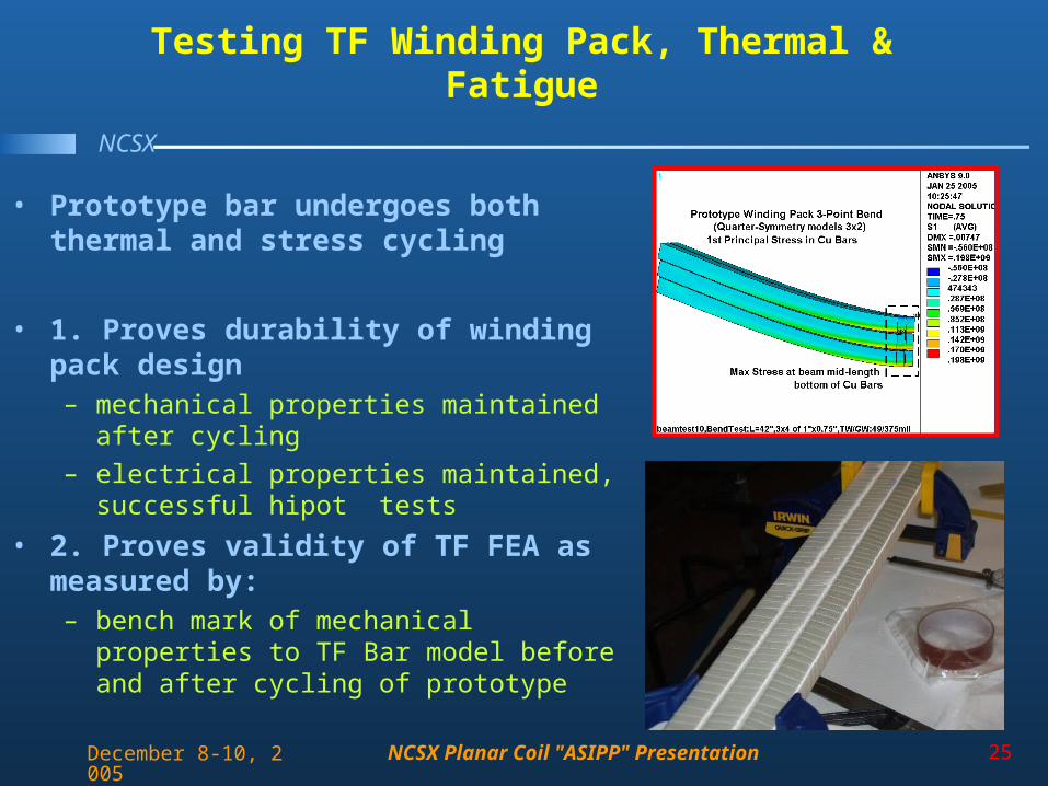
Testing TF Winding Pack, Thermal & Fatigue
• Prototype bar undergoes both thermal and stress cycling
• 1. Proves durability of winding pack design – mechanical properties maintained after
cycling
– electrical properties maintained, successful hipot tests
• 2. Proves validity of TF FEA as measured by:– bench mark of mechanical properties to TF
Bar model before and after cycling of prototype
NCSX Planar Coil "ASIPP" Presentation 26
NCSX
December 8-10, 2005
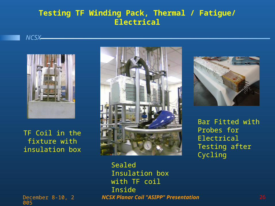
Sealed Insulation box with TF coil Inside
TF Coil in the fixture with
insulation box
Testing TF Winding Pack, Thermal / Fatigue/ Electrical
Bar Fitted with Probes for Electrical Testing after Cycling
NCSX Planar Coil "ASIPP" Presentation 27
NCSX
December 8-10, 2005
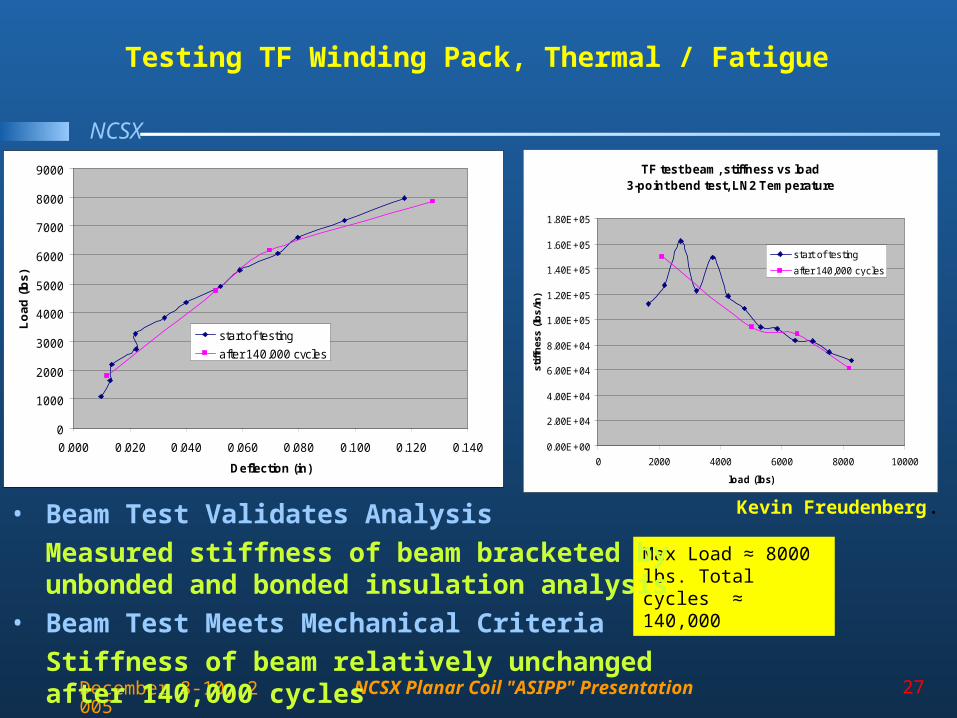
Testing TF Winding Pack, Thermal / Fatigue
0
1000
2000
3000
4000
5000
6000
7000
8000
9000
0.000 0.020 0.040 0.060 0.080 0.100 0.120 0.140
Deflection (in)
Lo
ad
(lb
s)
start of testing
after 140,000 cycles
TF test beam, stiffness vs load3-point bend test, LN2 Temperature
0.00E+00
2.00E+04
4.00E+04
6.00E+04
8.00E+04
1.00E+05
1.20E+05
1.40E+05
1.60E+05
1.80E+05
0 2000 4000 6000 8000 10000
load (lbs)
stif
fnes
s (l
bs/
in)
start of testing
after 140,000 cycles
Max Load ≈ 8000 lbs. Total cycles ≈ 140,000
• Beam Test Validates Analysis
Measured stiffness of beam bracketed by unbonded and bonded insulation analysis
• Beam Test Meets Mechanical Criteria
Stiffness of beam relatively unchanged after 140,000 cycles
Kevin Freudenberg.
NCSX Planar Coil "ASIPP" Presentation 28
NCSX
December 8-10, 2005
Outline
• Design• Analysis and Test• Fabrication• Topics for Discussion
NCSX Planar Coil "ASIPP" Presentation 29
NCSX
December 8-10, 2005
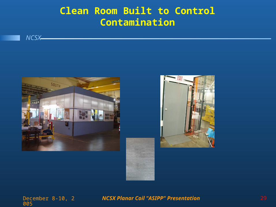
Clean Room Built to Control Contamination
NCSX Planar Coil "ASIPP" Presentation 30
NCSX
December 8-10, 2005
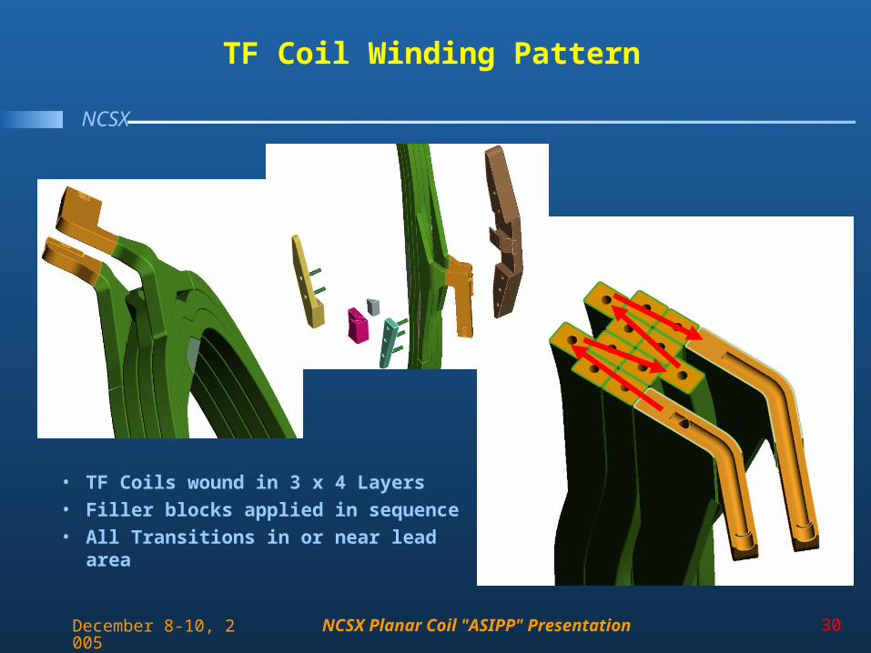
TF Coil Winding Pattern
• TF Coils wound in 3 x 4 Layers
• Filler blocks applied in sequence
• All Transitions in or near lead area
NCSX Planar Coil "ASIPP" Presentation 31
NCSX
December 8-10, 2005
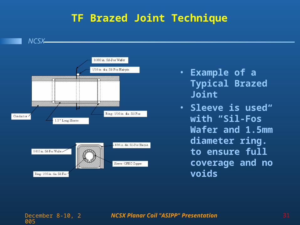
TF Brazed Joint Technique
• Example of a Typical Brazed Joint
• Sleeve is used with “Sil-Fos” Wafer and 1.5mm diameter ring. to ensure full coverage and no voids
NCSX Planar Coil "ASIPP" Presentation 32
NCSX
December 8-10, 2005
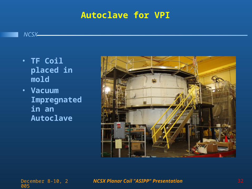
Autoclave for VPI
• TF Coil placed in mold
• Vacuum Impregnated in an Autoclave
NCSX Planar Coil "ASIPP" Presentation 33
NCSX
December 8-10, 2005
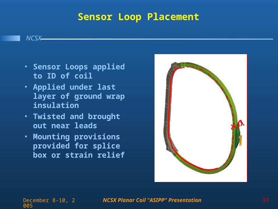
Sensor Loop Placement
• Sensor Loops applied to ID of coil
• Applied under last layer of ground wrap insulation
• Twisted and brought out near leads
• Mounting provisions provided for splice box or strain relief
NCSX Planar Coil "ASIPP" Presentation 34
NCSX
December 8-10, 2005
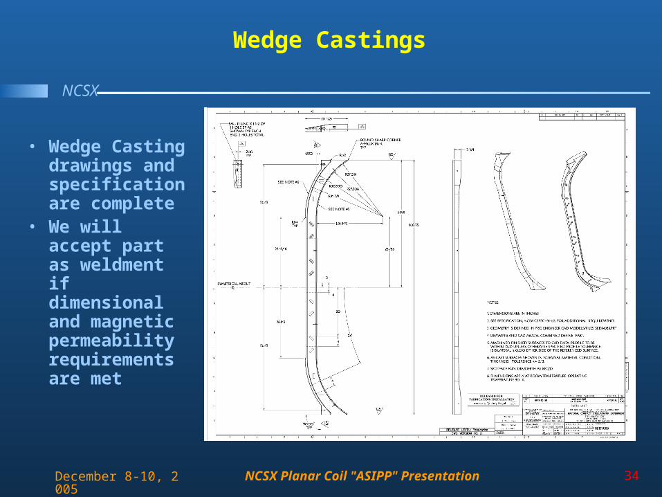
Wedge Castings
• Wedge Casting drawings and specification are complete
• We will accept part as weldment if dimensional and magnetic permeability requirements are met
NCSX Planar Coil "ASIPP" Presentation 35
NCSX
December 8-10, 2005
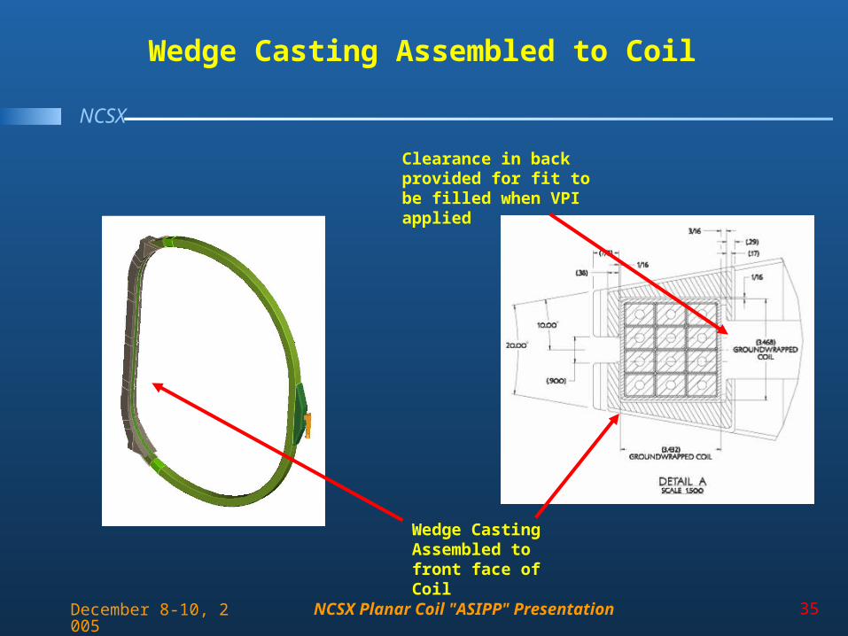
Wedge Casting Assembled to Coil
Wedge Casting Assembled to front face of Coil
Clearance in back provided for fit to be filled when VPI applied
NCSX Planar Coil "ASIPP" Presentation 36
NCSX
December 8-10, 2005
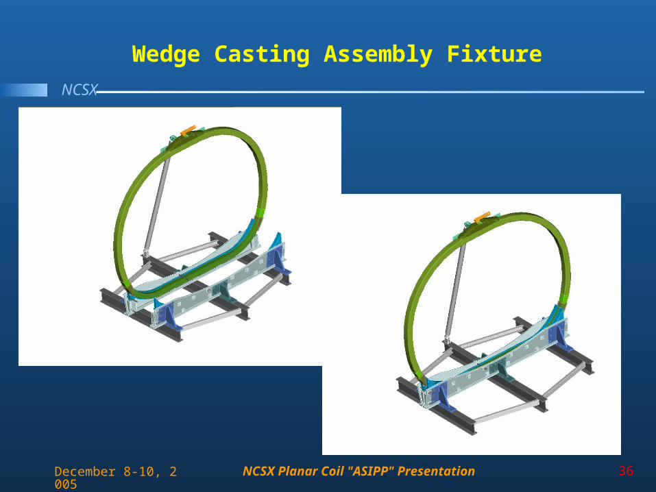
Wedge Casting Assembly Fixture
NCSX Planar Coil "ASIPP" Presentation 37
NCSX
December 8-10, 2005
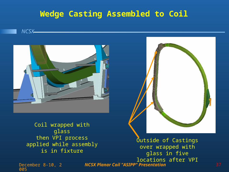
Coil wrapped with glassthen VPI process applied
while assembly is in fixture Outside of Castings over wrapped with glass in five
locations after VPI
Wedge Casting Assembled to Coil
NCSX Planar Coil "ASIPP" Presentation 38
NCSX
December 8-10, 2005
Fabrication / Measurement
• To maintain required tolerances measurements must be monitored and recorded during coil winding– Mandrel will be measured and placed precisely– Coil Geometry measured when removed from mandrel for ground
wrapping– Ground insulation thickness measured– Post VPI coil Geometry measured– Positioning of Coil for wedge casting installation
• Tracking of measurements will ensure consistency from coil to coil
• All measurements will be documented in fabrication procedure
NCSX Planar Coil "ASIPP" Presentation 39
NCSX
December 8-10, 2005
Fabrication / Test
• The plan for the electrical testing of the TF coils is to test:– Resistance– Inductance– Megger– Hipot– Impulse (used to identify breakdown in the turn to turn
resistance)
• Each of these tests at room temperature before and after cryogenic cycling for the first coil
• At room temperature for subsequent coils
NCSX Planar Coil "ASIPP" Presentation 40
NCSX
December 8-10, 2005
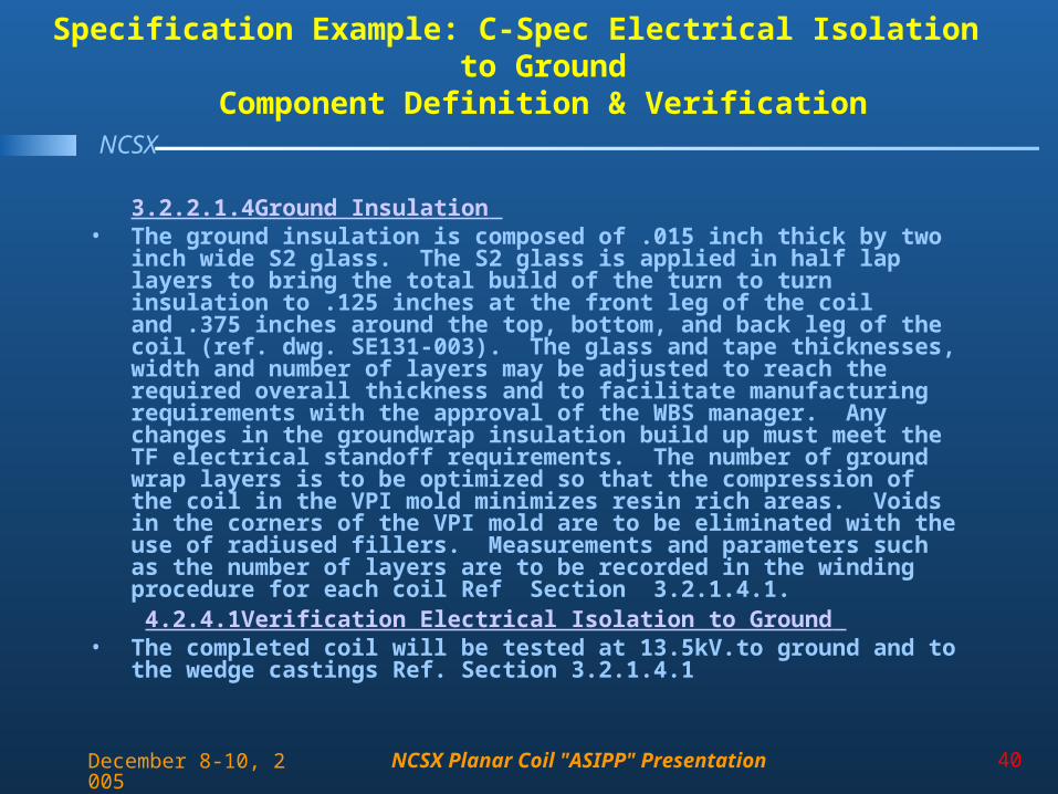
Specification Example: C-Spec Electrical Isolation to GroundComponent Definition & Verification
3.2.2.1.4Ground Insulation • The ground insulation is composed of .015 inch thick by two inch wide S2
glass. The S2 glass is applied in half lap layers to bring the total build of the turn to turn insulation to .125 inches at the front leg of the coil and .375 inches around the top, bottom, and back leg of the coil (ref. dwg. SE131-003). The glass and tape thicknesses, width and number of layers may be adjusted to reach the required overall thickness and to facilitate manufacturing requirements with the approval of the WBS manager. Any changes in the groundwrap insulation build up must meet the TF electrical standoff requirements. The number of ground wrap layers is to be optimized so that the compression of the coil in the VPI mold minimizes resin rich areas. Voids in the corners of the VPI mold are to be eliminated with the use of radiused fillers. Measurements and parameters such as the number of layers are to be recorded in the winding procedure for each coil Ref Section 3.2.1.4.1. 4.2.4.1Verification Electrical Isolation to Ground
• The completed coil will be tested at 13.5kV.to ground and to the wedge castings Ref. Section 3.2.1.4.1
NCSX Planar Coil "ASIPP" Presentation 41
NCSX
December 8-10, 2005
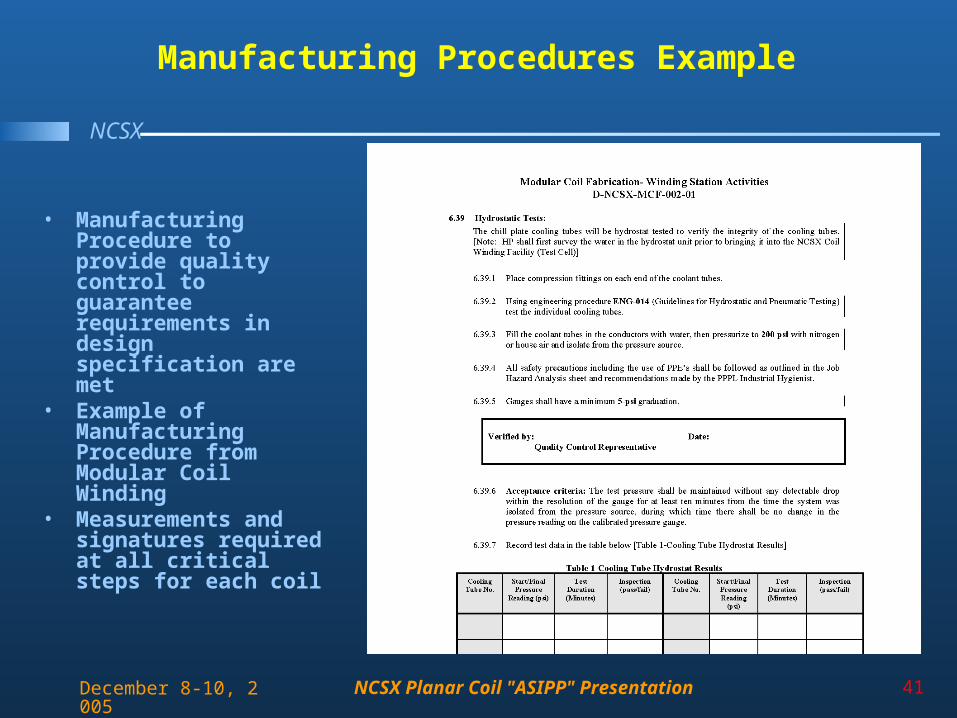
Manufacturing Procedures Example
• Manufacturing Procedure to provide quality control to guarantee requirements in design specification are met
• Example of Manufacturing Procedure from Modular Coil Winding
• Measurements and signatures required at all critical steps for each coil
NCSX Planar Coil "ASIPP" Presentation 42
NCSX
December 8-10, 2005
Outline
• Design• Analysis and Test• Fabrication• Topics for Discussion
NCSX Planar Coil "ASIPP" Presentation 43
NCSX
December 8-10, 2005
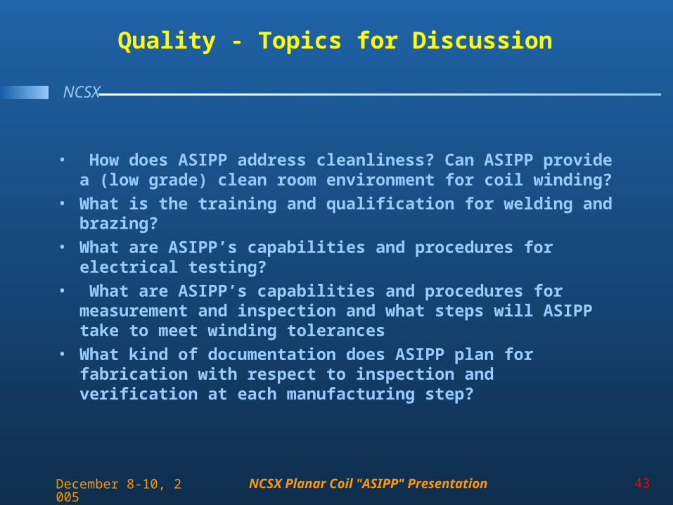
Quality - Topics for Discussion
• How does ASIPP address cleanliness? Can ASIPP provide a (low grade) clean room environment for coil winding?
• What is the training and qualification for welding and brazing?
• What are ASIPP’s capabilities and procedures for electrical testing?
• What are ASIPP’s capabilities and procedures for measurement and inspection and what steps will ASIPP take to meet winding tolerances
• What kind of documentation does ASIPP plan for fabrication with respect to inspection and verification at each manufacturing step?
NCSX Planar Coil "ASIPP" Presentation 44
NCSX
December 8-10, 2005
Management - Topics for Discussion
• We are interested in ASIPP’s approach to project management, specifically with respect to controlling quality and schedule.
• Would a single project manager and contact person be assigned to this project?
• How would priorities relative to other work at ASIPP be decided?
NCSX Planar Coil "ASIPP" Presentation 45
NCSX
December 8-10, 2005
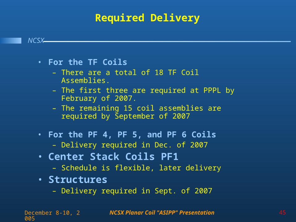
Required Delivery
• For the TF Coils– There are a total of 18 TF Coil Assemblies. – The first three are required at PPPL by February of
2007. – The remaining 15 coil assemblies are required by
September of 2007
• For the PF 4, PF 5, and PF 6 Coils– Delivery required in Dec. of 2007
• Center Stack Coils PF1– Schedule is flexible, later delivery
• Structures– Delivery required in Sept. of 2007