NASA Tech n ica I Memorandum · VIEWPORT CONCEPT FOR SPACE STATION MODULES By Freddie Douglas, ......
28
NASA Memorandum 7 Tech n ica I 4 Unclas 63/38 44644 NASA TM -86559 (NAS A-TB- National Aeronautics and Space Administration VIEWPORT CONCEPT FOR SPACE STATION MODULES By Freddie Douglas, 111 Structures and Propulsion Laboratory Science and Engineering Directorate August 1986 559) VIEYECRT CCNCEPT FOR SPACE STATION flODllLES (NASA) 28 p CSCL 228 George C. Marshall Space Flight Center MSFC - Form 3190 (Rev. May 1983) https://ntrs.nasa.gov/search.jsp?R=19870003159 2018-06-01T00:45:17+00:00Z
Transcript of NASA Tech n ica I Memorandum · VIEWPORT CONCEPT FOR SPACE STATION MODULES By Freddie Douglas, ......

NASA
Memorandum 7 Tech n ica I
4
U n c l a s 63/38 44644
NASA TM -86559
(NAS A-TB-
National Aeronautics and Space Administration
VIEWPORT CONCEPT FOR SPACE STATION MODULES
By Freddie Douglas, 111
Structures and Propulsion Laboratory Science and Engineering Directorate
August 1986
559) VIEYECRT CCNCEPT FOR SPACE S T A T I O N f l O D l l L E S (NASA) 28 p CSCL 228
George C. Marshall Space Flight Center
MSFC - Form 3190 (Rev. May 1983)
https://ntrs.nasa.gov/search.jsp?R=19870003159 2018-06-01T00:45:17+00:00Z
TABLE OF CONTENTS
INTRODUCTION .............................................................. BACKGROUND ................................................................ REQUIREMENTS .............................................................. GLASS SELECTION AND SIZING .............................................. OUTER COVER ............................................................... INNER PANE ASSEMBLY ...................................................... SAFETY COVER .............................................................. COATINGS ................................................................... VIEWPORT FRAME ............................................................ MAINTENANCE AND REPLACEMENT ........................................... WEIGHT ...................................................................... CONCERNS ................................................................... CONCLUSION ................................................................. APPENDIX
A . Calculat ions ....................................................... B . Sealing Material ................................................... C . D . E . Itemized Weights ...................................................
V e n t Port Dri l l ing ................................................. Damaged Pane Replacement Scenario ...............................
REFERENCES .................................................................
Page
1
1
1
1
7
7
11
11
11
1 3
15
15
15
17 20 20 20 2 1
23
PRECEDN PAGE aAw(
iii
LIST OF ILLUSTRATIONS
Figure Title Page
1 . 2 . Window comparison study ........................................... 3 . Module cluster ...................................................... 4 . Pane arrangement .................................................. 5 . Outer cover ........................................................ 6 . 7 . Inner pane assembly and frame ..................................... 8 . Safety cover .......................................................
Space station configuration .........................................
Inner pane assembly ................................................
9 . Viewport assembly .................................................. 10 . 11 .
Possible position and application of viewports ....................... Inner pane assembly handle ........................................
2
3
4
6
8
9
10
1 2
1 4
16
22
LIST OF TABLES
Table Title Page
1 . Required Glass Thickness .......................................... 5
2 . Material Selection 7
Viewport Meteoroid /Debris Analysis ................................. 4 . Module Meteoroid /Debris Analysis ................................... 1 9
................................................... 18 3 .
iv
.

TECHNICAL MEMORANDUM
VIEWPORT CONCEPT FOR SPACE STATION MODULES
INTRODUCTION
The Space Station (SS) , as shown in Figure 1, wil l be an Earth orbiting facility for science and industry. It can be used for physical and biological science experi- ments as well as pharmaceutical and manufacturing processes. This technical memo- randum addresses the generic design of a 20-in. diameter viewport for the modules. The capabilities of this viewport are meteoroid/debris protection (with no metallic outer cover), redundancies in its meteoroid/debris protection and in its pressure sealing systems, and ease of changeout for maintenance or repair.
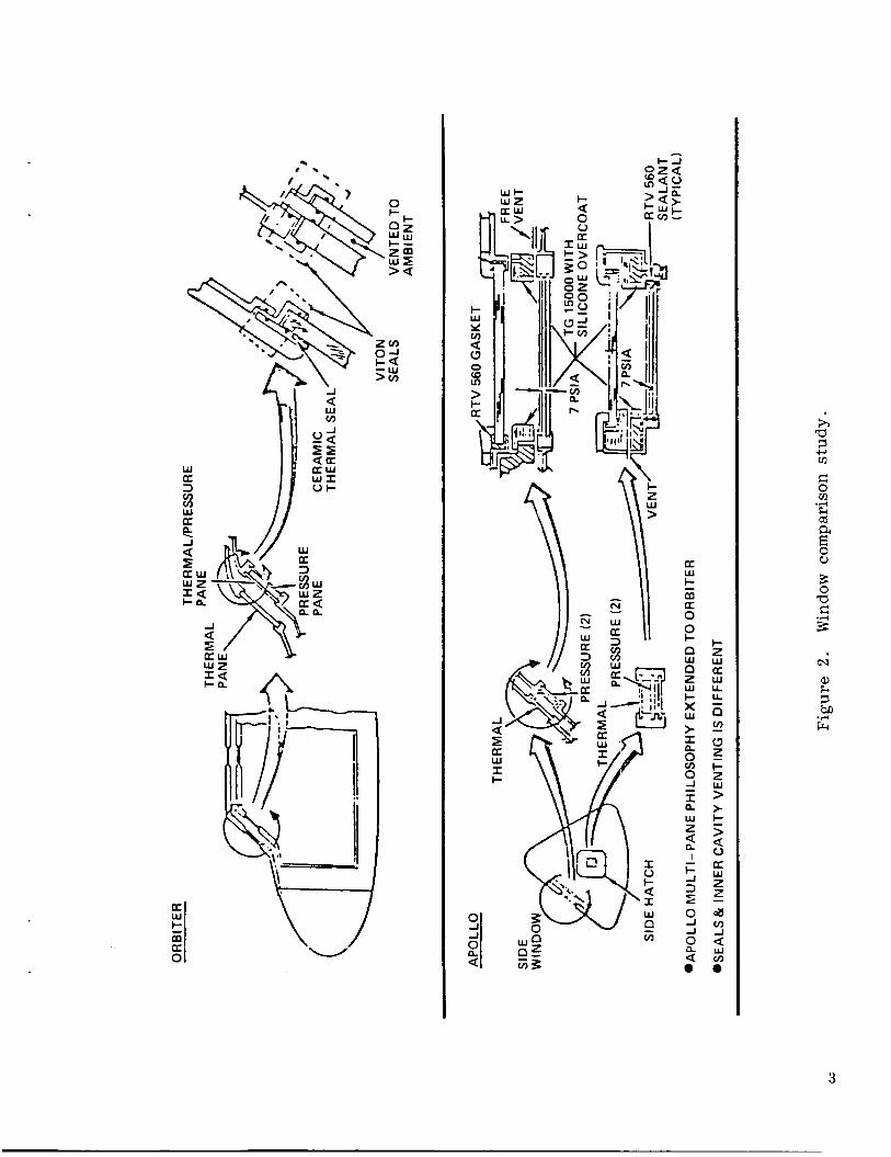
BACKGROUND
In the development of this viewport concept , existing designs were investigated to pool the best features and learn from past experiences. The previous SS type vehicles, such as Skylab and Spacelab, had metallic covers to protect their viewports. This study will investigate the application of a non-metallic cover for the modules viewports. Information for this investigation was gathered from as far back as the Apollo missions and included information from the Skylab, Space Shuttle , and Spacelab missions (Fig. 2 ) .
REQUIREMENTS
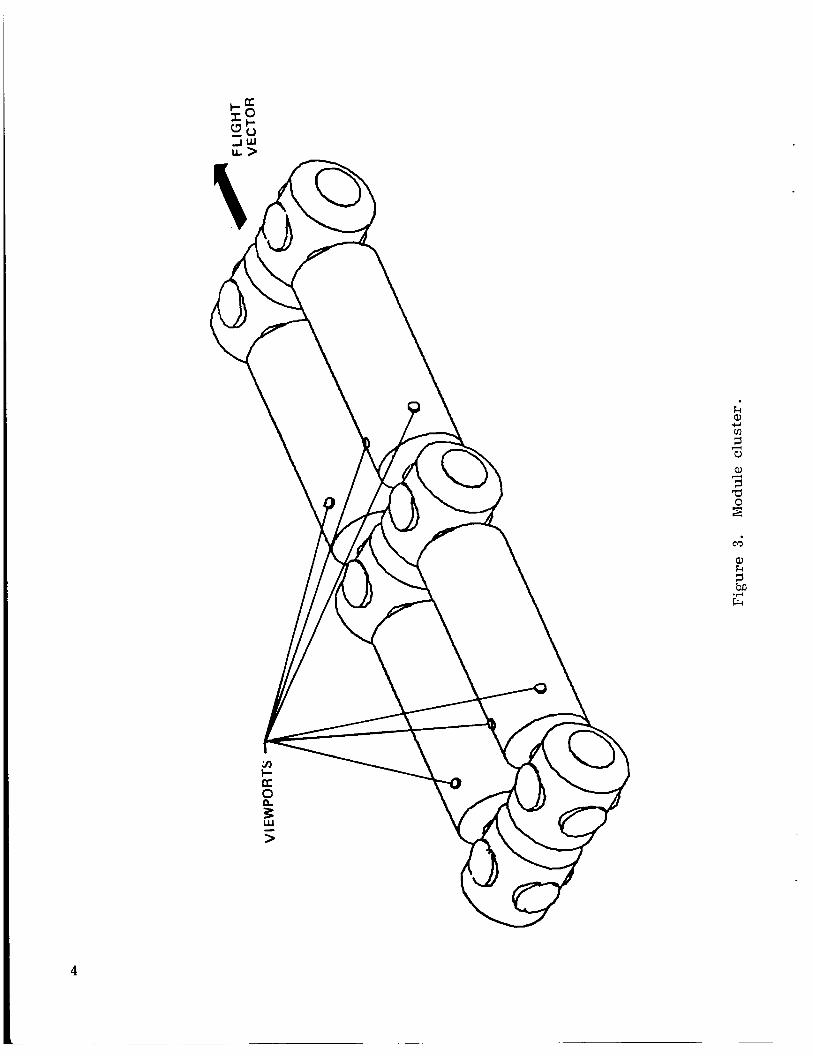
The Space Station Reference Configuration Description [ 21 identified the need for viewports to be located throughout the module cluster. This would permit viewing by two o r more persons at a time (Fig. 3 ) . The Reference Configuration also identi- fied the quantity of viewports; two 20-in. diameter and four 10-in. diameter viewports in the habitate modules and four 10-in. diameter viewports to be located in the labora- tory modules.
In general, viewports should retain their characteristics over the 10-year life of Viewports also should provide the modules with a minimum of maintenance and repair.
ease of changeout and a means of controlling factors indigenous to spacecraft view- ports. buildup , meteoroid/debris penetrations, and temperature extremes. port design will incorporate a glass outer cover that allows continuous Earth and celestial viewing,
These factnrs include ultraviolet (UV), infrared (IR) , sun glare, moisture The selected view-
GLASS SELECTION AND SIZING
Considering the desired capabilities , it was concluded that meteoroid /debris pro- tection would be the "driver" ,of the entire design. , The probability of no penetration (Po) for the four modules is 0.97. For one module the associated Po is 0.992 and for

.- a m
2
a w l CI
I- z W
W LL
a
LL a 2
z 0 I- z W > > I- > 0
W z z FZI
- a a
- v) J a Lu
."
h
.I+
3
@a
a k 1 ba
Frc .A
3
4

the viewports, Po is 0.996.
of the particle the viewport would have to defeat. mine the expected penetration depth of a direct impact on the viewport.
(For more detail, see Appendix A . ) The probabilities, t'ne particle densities ajid v-elocitiea, the dtit*;de I..--- ----A +r\ A n + n v . m i n n thn mocc V V C L C u o c u I," U G I , C I I L , . l . l L . a,.." .I.-"-
This information is used to deter-
TABLE 1. REQUIRED GLASS THICKNESS
Probability
Particle Diameter (em)
Density of Particle (g/cc)
Velocity of Particle (km/s)
E xp ec t ed Penetration (em)
No-Spall* Thickness (em)
Meteoroid
0.9999
0.00128
0.500
20
2.37
1.66 x
Debris
0.996
0.1397
2.81
10
0.508
3.56
* To prevent spalling on the back side of the glass, the necessary glass thickness is seven times the expected penetration [ 13, 151.
The effect of the outer glass and the next pane (the redundant pane) acting as a bumper-shell combination , was not taken into account when considering meteoroid/ debris protection. A meteoroid/debris analysis was run only on the redundant pane itself. At this time, means of determining the bumper effect are not available, later design refinements will incorporate the bumper effect.
Because of the desire to changeout on orbit, all panes (other than the redun- dant pane) are designed to hold the internal pressure of the module. The expected operating pressure will be 14 .7 psi. The proof pressure the viewport must support will be three times the operating pressure o r 4 4 . 1 psi [ 8 ] . area such that ample support can be given by the frame, all panes will be 22.80 in. in diameter. pane being the main source of meteoroid/debris protection (Fig. 4) .
To provide enough glass
Each of the panes in this design is required to hold 4 4 . 1 psi, with one
The glass and polycarbonate panes of this viewport configuration are expected The outer pane is not expected to survive a meteoroid/debris to perform as follows.
impact by the design particle but to act as a sacrificial shield for the primary meteoroid/debris protection pane. module internal pressure for the sole purpose of changeout on orbit. pane serves as the primary means of meteoroid/debris protection. 1 1 Lloii, ~ iiiis pane is not -cr,de,- +I-- - - A - - l a :m+nnnnl Lllt; l l l u u u l G I I l L C I l l U L yLb.UUUIb, ir, 811 effcrt to irlhihit flaw growth and prolong the useful life of the pane. load carrying pane (when the safety cover is not in use). protection from nicks and scratches during routine operation. required to be in place at all times; its main purpose is to provide quick pressure sealing during changeout.
In addition, the outer pane is expected to hold the The redundant
In routine opera- nnncciInn
The inner pressure pane will be the The safety pane provides
The safety pane is not
5

6
u I-
4
w w c a

Pane Type Material
Outer Fused Silica
Redundant Aluminosilicate
Inner Aluminosilicate
Safety Polycarbonate
The glass materials in this concept are tentative selections, and have not been confirmed by materials evaluation. The ability of the glass arrangement to prevent penetration or the sealing arrangement's ability to control atmospheric leakage from the module have yet to be qualified by testing. In the evaluation or use of any por- tion of this concept, it should be kept in mind that the design is based on a generic study and not a complete detail design and analysis. Design verification will be achieved through a structural and hypervelocity impact test program.
Design Benefit
Low Thermal Expansion Coefficient
High Strength, UV Control
High Strength, UV Control
High Strength to Weight
OUTER COVER
The frame that supports this pane and all the others is made of 2219-T87 A1 [3,7]. The pane is supported by Gask-0-Seal rings, 0.70-in. from the edge of the 20-in. diameter clear viewing area. These rings help prevent glass-to-metal contact which would increase the possibility of failure in the pane. against glass-to-metal contact, a silicone rubber cushion is placed between the pane and the frame wall. with tapped holes and inserts. countersunk, captive screws placed 22.25-deg apart (Fig. 5) .
For additional protection
The frame is held together by eight screws, 45-deg apart, mated The cover is attached to the viewport frame by 16
INNER PANE ASSEMBLY
This frame will provide easy access (for changeout) to either the redundant or inner pressure pane. the inner pane assembly (IPA) (Figs. 6 and 7) .
The combination of these two panes and their frame is called The location of Gask-0-Seals and
7

w I- O z
.-
t

I z K w I- I-
n a
5 B i v) a
I
UI
I
0
9

I 0
IT r J 1 I
I
I w L C
--
10

silicone rubber cushions is the same as that in the outer cover. frame is held together by 8 bolts. 45-deg apart. with inserts to eliminate possible leak paths. same bolt configuration as the redundant pane frame except that it uses standard nuts instead of tapped holes with inserts. It also has an extension which facilitates attach- ment to the viewport frame (Fig. 7).
The redundant pane These bolts mate with tapped holes
The inner pressure pane frame has the
A vent path to the inside of the module was provided to prevent pressure build- up between the panes of the inner pane assembly. i ts center line at the point where the redundant and inner pane frames meet (Fig. 6) . The center line of this hole is aligned with the vent path provided for the rest of the viewport system in the viewport frame. To facilitate the venting process, O-rings are placed around each frame to even more isolate the area between the panes and to meet a desired capability of redundancy in pressure sealing. At the point where the two frames meet, a layer of silicone rubber is placed to add to the seal between the frames (see Appendix B ) .
The path is a 0.25-in. hole with
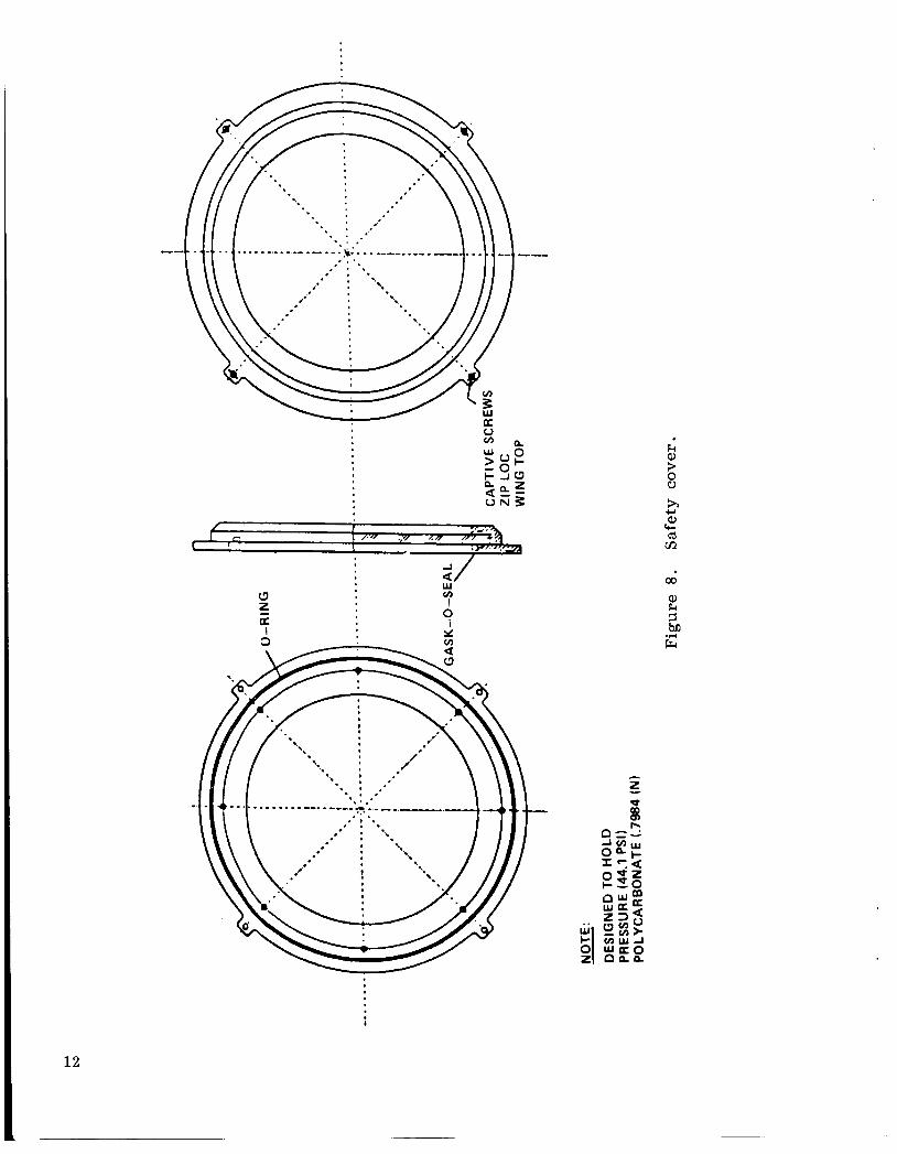
SAFETY COVER
The safety (internal) cover's attachment method is very similar to that of the outer cover except that extensions are placed 45-deg from the vertical and horizontal at four places (Fig. 8). screws; one on each extension. Therefore, attachment of the safety cover to the inboard side of the viewport frame can be accomplished with a minimum amount of effort on the part of an astronaut. the inner pressure pane. Each time contact is made with any of the panes, their strength properties are reduced. flaws in them and contact with any glass pane can initiate flaw propagation and greatly increase its chances of failure. In the same manner, chemicals, greases and other substances may cause crazing of the glass which is a form of flaw propagation.
This facilitates the placement of four wing-top captive
This cover will prevent accidental contact with
This is due to the fact that all glass materials have
COATINGS
Another problem associated with spacecraft windows is moisture collection on the panes. This condensation can be controlled by coating the panes with various types of tin oxides (differences are due to electrical power requirements and thicknesses), or internal and external wire mesh (Fig. 7 ) . In this design the coatings are placed on the surfaces of each pane facing the airspace and possibly the inboard surface of the outer pane. the outboard side of the outer pane to control IR and sun glare (Fig. 5) . This type of coating was used on the Skylab S190 window.
It is also suggested that a coating of vaporized gold be placed on
VIEWPORT FRAME
The viewport frame provides all the attach points for the outer and safety covers in addition to those required for the inner pane assembly (Fig. 6 ) . provides the necessary vent paths and means of attachment to the skin of the module.
It also
11
I.
1 2
a/ w v) I 0
I
00
Q, k r.
d

On the inboard side of the viewport frame, safety cover captive screw mating points are 45 aeg from the verticai and horizontal, four places, as described above for the safety cover attachment (Fig. 6 ) . A t the alternate 45-deg positions, exten- sions are flush with the outer edge of the attachment area. These, along with the other extensions are the points where the inner pane assembly attaches to the view- port frame via countersunk screws. These screws also align the center line of the inner pane assembly's vent port with the vent port in the viewport frame.
On the outboard side of the viewport frame, the outer cover captive screw mating points are placed beneath the overhang of the viewport frame (Fig. 6 ) , as described previously for the outer cover attachment.
For additional support of the viewport frame, seven stiffeners of 0.25411. wide cross section and one stiffener of 0.50-in. cross section (in which the vent port is located) are placed at 45-.deg increments, on the inboard side of the viewport (Fig. 9) . The same total number of stiffeners are used on the outboard side; each having a 0.25-in. wide cross section.
To meet the desired venting capabilities, a 0.25-in. diameter vent port is used
The to relieve pressure buildup between the redundant and inner pressure pane. This vent port also vents the area between the redundant pane and the outer cover. center line of this vent coincides with the center line of the stiffener and is at the same stiffener inclination (see Appendix C) . At the mouth of the vent port on the inboard side, a quick disconnect or a permanent attachment can be installed to facili- tate the venting of the areas between the panes. The design of a venting system is not addressed in this report.
The module waffle pattern consists of rings 10 in. apart along the length of the module and longitudinal stiffeners 15-deg apart along the circumference. intersection of these rings and stiffeners is a node that provides a place for attach- ment to the shell of the module. facilitate viewport assembly.
At the
Part of this waffle pattern will be modified to
In attaching the frame to the module shell, a section of the module waffle pattern is modified: three complete nodes, eight half nodes, and four quarter nodes will be removed. Also, the area where the viewport will be inserted shall be machined to 0.25 in. rather than its normal 0.125 in. The skin of the frame is 0.25-in. thick. It is welded in place with a double "v" weld on the inboard and outboard sides [ 101. This weld serves not only as a load carrier but also as a pressure seal weld.
MAINTENANCE AND REPLACEMENT
In the event of failure in one or more panes, a replacement scenario is required (see Appendix D ) . easy access comes into play. well.
This is where unit construction, minimal number of parts, and This scenario can be applied to general maintenance as
It is expected that a ifiiiiiiid aiiuuiit of maintenance wii i be required to maintain
The actual changeout time interval has not been determined. peak operating properties; O-rings and Gask-O-Seal rings will require the most atten- tion.
13

--. w ..-- 3 -_ __. . a
ao Vv)
I
I 14

WEIGHT
The weight for the 20-in. -diameter viewport is approximately 300 lb. Optimiza- tion of the structural parts is a potential method of reducing the weight by decreasing the amount of material used in the framework. Also, possible savings can be achieved by using higher strength glass with the same desired capabilities mentioned earlier (UV control and low thermal expansion). Without any changes to the present con- figuration, the weight is not unreasonable. The Spacelab Window Adapter Assembly (SWAA) weighs in excess of 300 lb. window, which was 1.60 in. thick, and weighed approximately 90 lb , is compared to the redundant pane used in this configuration, it can be seen that their weights are about the same (see Appendix E ) . reason [17] .
If Skylab's Multiple Docking Adapter (MDA)
Therefore this configuration's weight is within
CONCERNS
The location of the viewports in the module cluster relative to the flight vector is important (Fig. 3 ) . the smallest flux of meteoroid/debris particles. This position may be 180 deg from the flight vector. This may be the worst position for Earth and celestial viewing because it may fall in the middle of the module cluster. If the viewports are placed facing in the same direction as the flight vector, the possibility of impact increases in addition to the size of particle that must be defeated. glass thickness, the weight of the viewport, and the overall weight of the module itself. the orbiter can lift the module to i ts correct orbit. viewport is not a task that should be taken lightly.
I t is recommended that they be placed in areas they will see
This in turn increases the required
If the weight of the module is too high, there is some question as to whether Therefore, the location of the
CONCLUSION
At this time the reference configuration calls for 20- and 10-in.-diameter view- ports for nonexperimental, continuous viewing (Fig. l o ) . sented in this document incorporates various qualities that hopefully will make it viable in the C / D phase of the module development program. concepts used in the Apollo, Skylab, and STS mission series (Fig. 2 ) .
The viewport design pre-
Its design was derived from
This design provides meteoroid/debris protection, ease of changeout, unit con- struction, moisture buildup control, UV and IR control, vent paths to prevent pres- sure buiid-up between the panes, and anytime Earth o r ceiestiai viewing by two persons. designs that use metallic outer covers to protect the glass from meteoroid /debris penetrations. outer cover, and from a design point of view, another leak path to seal. These factors were taken into consideration in developing this viewport design. A design having a non-metallic cover will save time in not having to follow opening and closing procedures, and will eliminate possible leak paths in the area where the handle of a metallic cover would be installed. Once testing begins, it is expected that this view- port design will meet all requirements.
The viewport concepts used in the past (long duration flights) rendered
This provided limited viewing, as well as the task of removing the
15

w -I 3 n 0 E m a I
k 0 a
a
16

APPENDIX
A . Calculations
1. Particle Sizing
The probability of no penetration (Po) for four modules is 0 . 9 7 .
Po (1 module) = ( 0 . 9 7 ) 0 * 2 5 = 0.992
0 . 9 9 2 = Po viewport * Po module.
For equal distribution of Po between viewports and modules:
Po viewport = ( 0 . 9 9 2 ) Oo50 = 0.996
Furthermore
P viewport = Po meteoroid * Po debris 0
Po module = Po meteoroid * Po debris .
For these probability breakdowns, it is shown that the debris particle size is the dominant one. particle size associated with 0 .996 probability is the selected design particle size. This particle size was selected because at the assigned probability, it represents a particle size twice as big as the size that the module will see.
It in turn would be the design driver. Also from the data, the
The equations used to generate the tables below [ 11,121 are as follows:
Probability of no penetration
- N A T P = e 0
where
2 N = meteoroid/debris flux ( / m y r )
2 4 = prejected 2re2 (E )
T = exposure time (y r )
1 7

Flux equation
meteoroid
log N = -14 .37 + log G + log S - 1 . 2 1 3 log m
where
G = gravitational defocusing constant
S = Earth shielding constant
m = mass of particle (g/cc)
debris
log N = - 5 . 4 6 - 2 .52 log d
where
d = diameter of particle (cm) .
From the following tables, it can be inferred that the debris particle would be the design driver for the viewports.
TABLE 3. VIEWPORT METEOROID/DEBRIS ANALYSIS
Particle (Diameter cm)
Meteoroid (x10- 3, Debris
0 .999
0 . 9 9 8
0 .997
0 .996
0 .995
0 .994
0 .993
0 .992
1 . 8 7
1 . 5 5
1 . 3 9
1 . 2 8
1 .20
1 . 1 4
1 .10
1 . 0 6
0 .240
0 . 1 8 4
0 .157
0 . 1 3 9
0 .128
0 .119
0 .112
0 .106
18
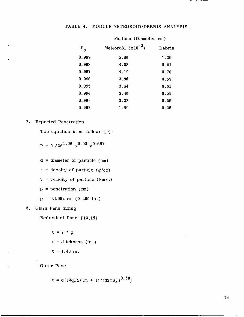
TABLE 4. MODULE METEOROID/DEBRIS ANALYSIS
0.999 0.998 0.997 0.996 0.995 0.994 0.993 0.992
2. Expected Penetration
The equation is as follows [ 91 :
1.06 0.50 v0.667 P = 0.53d P
d = diameter of particle (cm)
P = density of particle (g/cc)
v = velocity of particle (km/s)
p = penetration (cm)
p = 0.5092 cm (0.200 in.)
3. Glass Pane Sizing
Redundant Pane [ 13,151
Particle (Diameter cm)
Meteoroid (x10- 3, Debris
t = 7 * p
t = thickness (in.)
t = 1.40 in.
Outer Pane
5.66 4.68 4.19 3.90 3.64 3.46 3.32 1.69
1.20 0.91 0.78 0.69 0.63 0.59 0.55 0.25
0.50 t = d[(3qFS(3m + 1)/(32mSy) 1
19

d = diameter (in.)
q = uniformly distributed load (psi)
FS = factor of safety
Sy = modulus of rupture
m = inverse of Poisson ratio
t = 0.8535 in. 111
Inner Pressure Pane
t = 0.7610 in.
Safety Pane
t = 0.7904 in.
B . Sealing Material
0-Rings - Silicone
Gask-0-Seals - Silicone
Silicone Sheet - Silicone
All per SAE-AMS- 3304 - (Silicone Rubber).
C . Vent Port Drilling
The vent port in the viewport frame is made by drilling from the outboard side This location is slightly beyond the of the frame, 97 deg from the outboard surface.
intersection of the vent port center line of the inner pane assembly. the vent port section above the vent for the area between the redundant and outer panes is resealed.
After drilling,
D . Damaged Pane Replacement Scenario
Case 1. Outer Cover
A.
B . Vent air space.
Replace outer cover on EVA
20

Case 2. Outer Cover and Redundant Pane
A. Replace outer cover, EVA required
B . Remove safety cover
C. Remove inner pane assembly, repair as needed [to remove the IPA from the frame, the IPA handle is provided (Fig. ll)] .
D. Replace inner pane assembly
E. Replace safety cover
F . Vent air spaces
Case 3. Outer Cover and Both Inner Pane Assembly Panes
A . Same as Case 2 .
Case 4. Outer Cover, Inner Pane Assembly, Safety Cover
A. Same as Case 2 , steps A-D
B. Repair safety cover as needed and replace
C. Evacuate air spaces.
NOTE: The maintenance scenario will be the same as presented above. "repair as neededt' o r "replace" will usually mean replacement of pane and frame as a unit and replaced with another complete unit.
The phrase
E . Itemized Weights
Frame (skin included)
Safety cover
Outer cover
IPA
46 .12
56 .80
64 .68
144 .70
Glass only
Redundant
Pressure
Outer
Safety
Frame only (Total Al)
Total 312.30 lb
5 4 . 3 0
29 .52
27 .72
1 4 . 2 0
Total 125.74 lb
186.56 lb
21

. .
U
-E-
-
a, G s c h
22

1. Roark, Raymond J.: Formulas for Stress and Strain. McGraw-Hill, 4th ed. , 1965.
2. Space Station Reference Configuration Description, JSC- 19989, August 1984.
3. Aluminum Alloy 2219, Plate and Sheet , Federal Specification QQ-A- 250/30A , November 19, 1982.
4. Timoshenko and Woinowsky-Krieger : Theory of Plates and Shells. McGraw-Hill , 2nd ed. , 1959.
5. Corning Glass Works Properties Book, 1963.
6. Plastics For Aerospace Vehicles Part I1 Transparent Glazing Materials , MIL-HDBK 17A , January 1971.
7. Metallic Materials and Elements for Aerospace Vehicle Structures , MIL-HDBK 5D, June 1, 1983.
8. Structural Strength Program Requirement , MSFC-HDBK 505A, January 1981.
9. Flaherty, Robert E . : Impact Characteristics in Fused Silica. AIAA Paper No. 69-367, May 1969.
10. Specification: Welding, Aluminum Alloys. MSFC-SPEC-504B , August 15, 1984.
11. Batla, Fahim A . : Station for Hypervelocity Impacts by Meteoroids and Space Debris. P. E . , August 9 , 1985, unpublished.
Methodology of Design and Analysis of External Walls of Space Ph.D. ,
1 2 . ST System Meteoroid Analysis. SE-03, Section 0 , Part 2 ; Lockheed Missile and Space Co. (LMSC/D 668777A), Addendum 1 , January 15, 1982.
13. McHugh, A . H . and Richardson, A . T. : Hypervelocity Particle Impact Damage to Glass. North American Aviation, STR 241, April 14, 1974.
14 . Designing with Lexan, General Electric, CDC-536C( 5/84) ; Lexan Products Division , Plastics Group.
15. Cour-Palais E G , : Hypervelocity Impact Investigations and Meteoroid Shie!dir,g Experience Related to Apollo and Skylab. Johnson Space Center, NASA.
16. Shoemaker, Arthur F . : Glass In The Space Age. Aerospace Advanced Products Department, Corning Glass Works, Corning , N Y , 15th National SAMPE Technical Conference, October 4- 5 , 1983. t
17. Memo A90-480-SLP- 860277, McDonnell Douglas Technical Services Company, Huntsville, A L , March 2 4 , 1985.
2 3
APPROVAL
2 4 i
VIEWPORT CONCEPT FOR SPACE STATION MODULES
By Freddie Douglas, I11
The information in this report has been reviewed for technical content. of any information concerning Department of Defense or nuclear energy activities or programs has been made by the MSFC Security Classification Officer. This- report , in its entirety, has been determined to be unclassified.
Review
A. A. McCool D i r e c t o r , S t r u c t u r e s and P ropu l s ion L a b .
.
*US. G O V E R N M E N T PRINT1 N G OFF ICE 1986631-058/40001

1. REPORT NO. 2. GOVERNMENT ACCESSION NO. 3. RECIP IENT 'S CATALOG NO.
I
4. TITLE AND S U B T I T L E
Viewport Concept for Space Station Modules Viewport Concept for Space Station Modules 5. REPORT DATE
August 1986 6. PERFORMING ORGANIZATION CODE
August 1986 6. PERFORMING ORGANIZATION CODE
I
4. TITLE AND S U B T I T L E I 15. REPORT DATE
National Aeronautics and Space Administration Washington, D. C. 20546
7. AUTHOR(S)
Freddie D w s . 111 9. PERFORMING ORGANIZATION NAME AND ADDRESS
George C. Marshall Space Flight Center Marshall Space Flight Center, Alabama 35812
12. SPONSORING AGENCY N A M E AND ADDRESS
Technical Memorandum
8. PERFORMING ORGANIZATION REPOR r #
10. WORK UNIT NO.
1 1 . CONTRACT OR GRANT NO.
13. T Y P E OF REPOR;' & PERIOD COVERED
I 15. SUPPLEMENTARY NOTES
Unclassified Unclassified
Prepared by Structures and Propulsion Laboratory, Science and Engineering I Directorate. I
27 NTIS
This report addresses the generic design of a 20-in. diameter viewport for the It should possess the capabilities of meteoroid /debris protec-
In addition, it should provide ease of change out for The design does not take into account the bumper-shield
space station modules. tion (with no metallic cover), redundancies in its meteoroid/debris protection, and pressure sealing systems. maintenance or repair. effect of the outermost panes in the meteoroid/debris analysis.
i I
7. KEY WORDS
Viewport Space Station Meteoroid Debr i s Rep laceab le
19. SECURITY CLASSIF. (d thh -part) 20. SECURITY C L A
-I 18. DISTRIBUTION STATEMENT
;IF. (of thh pee )