NASA Low-Speed Centrifugal Compressor for 3-D Viscous Code ...€¦ · NASA LOW-SPEED CENTRIFUGAL...
15
NASA AVSCOM Technical Memorandum 103710 Technical Report 91-C-003 NASA Low-Speed Centrifugal Compressor for 3-D Viscous Code Assessment and Fundamental Flow Physics Research M.D. Hathaway Propulsion Directorate U.S. Army Aviation Systems Command Lewis Research Center Cleveland, Ohio J. R. Wood National Aeronautics and Space Administration Lewis Research Center Cleveland, Ohio and C.A. Wasserbauer Sverdrup Technology, Inc. Lewis Research Center Group Brook Park, Ohio Prepared for the 36th International Gas Turbine and Aeroengine Congress and Exposition sponsored by the American Society of Mechanical Engineers Orlando, Florida, June 3-6, 1991 US ARMY NASA AVIATION SYSTEMS COMMAND AVIATION R8T ACTIVITY https://ntrs.nasa.gov/search.jsp?R=19910010731 2020-04-17T12:54:47+00:00Z
Transcript of NASA Low-Speed Centrifugal Compressor for 3-D Viscous Code ...€¦ · NASA LOW-SPEED CENTRIFUGAL...

NASA
AVSCOMTechnical Memorandum 103710
Technical Report 91-C-003
NASA Low-Speed Centrifugal Compressorfor 3-D Viscous Code Assessment andFundamental Flow Physics Research
M.D. HathawayPropulsion DirectorateU.S. Army Aviation Systems CommandLewis Research CenterCleveland, Ohio
J. R. WoodNational Aeronautics and Space AdministrationLewis Research CenterCleveland, Ohio
and
C.A. WasserbauerSverdrup Technology, Inc.Lewis Research Center Group
Brook Park, Ohio
Prepared for the36th International Gas Turbine and Aeroengine Congress and Expositionsponsored by the American Society of Mechanical EngineersOrlando, Florida, June 3-6, 1991
US ARMY
NASA AVIATIONSYSTEMS COMMANDAVIATION R8T ACTIVITY
https://ntrs.nasa.gov/search.jsp?R=19910010731 2020-04-17T12:54:47+00:00Z

NASA LOW-SPEED CENTRIFUGAL COMPRESSORFOR 3-1) VISCOUS CODE ASSESSMENT ANDFUNDAMENTAL FLOW PHYSICS RESEARCH
M.D. Hathaway J.R. Wood
C.A. Wasserbauer
Propulsion Directorate NASA Lewis Research Center
Sverdrup Technology. /tie.U.S. Annv Aviation Systems Command
Cleveland, Ohio 44135
Lewis Research Center GroupCleveland, Ohio 44135
Cleveland Ohio 44135
ABSTRACT
A low speed centrifugal compressor facility recently built bythe NASA Lewis Research Center is described. The purpose of thisfacility is to obtain detailed flow field measurements for computa-tional fluid dynamic code assessment and flow physics modelling insupport of Army and NASA efforts to advance small gas turbine en-gine technology. The facility is heavily instrumented with pressureand temperature probes, both in the stationary and rotating framesof reference, and has provisions for flow visualization and laser ve-locimetry. The facility will accommodate rotational speeds to 2400rptn and is rated at pressures to 1.25 atm. The initial compressorstage being tested is geometrically and dynamically representativeof modern high-performance centrifugal compressor stages with theexception of Mach number levels. Preliminary experimental inves-tigations of inlet and exit flow uniformity and measurement repeata-bility are presented. These results demonstrate the high quality of thedata which may be expected from this facility. The significance ofsynergism between computational fluid dynamic analyses and exper-imentation throughout the development of the low speed centrifugalcompressor facility is demonstrated.
NOMENCLATURE
b = Impeller exit blade height, cmD = Impeller exit tip diameter, cmH = Ideal head rise, mN = rotational speed, rad/secQ = Volumetric flow rate, m a /secR = radius, cmU = rotor blade speed, m/secV = Absolute velocity, m/secW = Relative velocity, m/secZ = axial coordinate, cmv = kinematic viscosity, m2 /sec
Subscripts
= plenum= impeller inlet survey station
2 = impeller exit survey stationfs = free streamr = radial directiont = Impeller tipz = axial direction
INTRODUCTION
Centrifugal compressors are widely used in a variety of appli-cations because of their ability to achieve high pressure ratios in arelatively short axial distance and due to their rugged construction.Centrifugal compressors are characterized by long blade channelswhich have complex in- and out-of-plane turns with high curva-ture. Due to the complex turning of the flow and rotational forces,strong secondary flows are produced. These secondary flows, alongwith separated flow regions, lead to strong cross-flow velocity com-ponents which transport fluid with low momentum and high total-pressure loss into the main stream. Attempts to model the com-plex three-dimensional nature of the flow in centrifugal compressorshave generally met with little success, although recently a numberof investigators have produced numerical computations which showgreat promise (e g., Moore and Moore, 1989, 1990, Hah et al., 1988,1989, Dawes, 1988). Designers of centrifugal turbomachines havetherefore had to rely heavily on empiricism. As a result, centrifu-gal compressors tend to have lower efficiencies than their axial-flowcounterparts. For significant improvements in the aerodynamic per-formance of centrifugal compressors to be realized a more detailedunderstanding of the fundamental flow physics is required. Syner-gism between experiments and computational analyses will undoubt-edly play a key role in developing this understanding.
With the advent of more powerful computers and further de-velopment of three-dimensional Navier-Stokes codes, the numeri-cal prediction of centrifugal compressor flow fields has greatly im-proved. However, assessment of the ability of these predictionsto accurately model the fundamental physics of centrifugal com-pressor flow fields is largely lacking. Krain and Hoffman (1989),Eckart (1976), Joslyn et al. (1990), Young et al. (1987), Japiskeand Karon (1989), Hayami et al., (1984), Johnson and Moore (1980,

1983) have reported measurements of flows in centrifugal compres-sors which have shed light on many aspects of centrifugal compres-sor flow physics. Most of these investigations however, have lackedthe detailed measurements required to assess the ability of three-dimensional viscous codes to accurately model the fundamental flowphysics. Furthermore, none of the investigations yielded detailed in-formation within viscous regions (i e., blade boundary layers).
The NASA Low Speed Centrifugal Compressor (LSCC) was de-signed and built in order to obtain the detailed measurements whichare required to assess three-dimensional viscous codes and to de-velop more sophisticated models of the various physical phenomenaoccurring in centrifugal compressors. This paper describes the major
components and instrumentation of the low speed centrifugal com-pressor facility. Experimental investigations of inlet and exit flowuniformity, measurement repeatability and overall performance arealso presented which demonstrate the high quality of the data whichmay be expected from this facility. The significance of synergismbetween computational fluid dynamic (CFD) analyses and experi-mentation throughout the development of the low speed centrifugalcompressor facility is demonstrated.
FACILITY
Figure 1 depicts the major elements of the low speed centrifugalcompressor facility. Air is drawn in from a filtered vent in the roofpast a bank of steam pipes and louvers designed to control the airtemperature to within ± 1 °F for mass flows up to 45 kg/s. Tileflow then enters the facility room and is then drawn into the plenumthrough a bank of flow straighteners which are contained between
two mesh screens. The air passes through a specially designedbellmouth with a 10:1 area contraction. The turbulence levels at thebellmouth exit are expected to be less than 1 percent, and will bemeasured in the near future along with the impeller inlet turbulenceprofile. The flow then enters the compressor and exits through aspecially designed throttle valve at the entrance to the collector.The throttle valve consists of two concentric rings with overlappingholes drilled in each ring which slide relative to each other toproduce a throttle. This throttle valve design was chosen to minimizecircumferential asymmetry in the exit static pressure distributionsuch as is typically found in scroll-type collectors. The bellmouth,inlet transition piece, and shroud flow path were machined togetherto minimize any boundary layer disturbance due to a step in theflow path. Altitude exhaust capability of 660 mm-Hg (26 in-Hg)of vacuum enables mass flow rates up to 45 kg/sec. A 1.115 MW(1500-hp) electric motor and gear reducer drives the facility to amaximum speed of 2400 rpm. A complete description of the facilityis provided by Wood et al. (1983).
TEST COMPRESSOR
During the design of the low speed compressor several condi-tions were imposed. First, the design should reflect the geometricand dynamic parameters that were deemed to be representative ofmodern compressors and second, the blade lean should not be sosevere that laser access would be precluded. The design parametersfor the low speed centrifugal compressor are given in table 1 whiletable 2 shows a comparison of some low speed centrifugal compres-sor stage parameters with those from several high speed centrifugal
SHROUD--Ii
- ITRANSITION PIECE
I I
v–BELLMOUTH INLET i II
I I1 IIl F AIR STRAIGHTENER II II
t I11 11 BELLMOUTH-7 IIll 11 FLEXIBLE SEAL-7i II
PLENUM
11 ^111rrr--^ ^ ^ I
VOLUTE COLLECTOR
THROTTLE
I VALVE
I // /–COMPRESSOR ASSEMBLYI /I /
F SLIP-RINGASSEMBLIES
/—TORQUE
/ SENSOR / r—MOTOR
/ / I COOLINGRIOWFA
2.4 m t fl
BEDPLATE—
L 1 MVARIABLE
PRESSURE RAKE SPEEDLOCATIONS
ALTITUDE EXHAUST
DRIVEMOTOR
Figure 1 Low speed centrifugal compressor facility.

Table l Design parameters for low speed centrifugal compressor
Stage:Flow rate, kg/sec. 30Total pressure ratio 1.166
Estimated efficiency 0.90
Rotor:Total pressure ratio 1.173
Estimated efficiency 0.934Rotor speed 1920'Inlet hub-tip radius ratio 0.5Inlet span, cm 22.042Inlet tip radius, cm 42.939Exit radius, cm 76.200Exit blade height, cm 13.740Axial clearance, cm 0.5725'Number of blades 20Reynolds number, U,D,/vn 16x10"Inlet tip relative Mach number 0.31Exit absolute Mach number 0.29
Diffuser:
Rotor exit/vane inlet radius ratio 1.08
Number of vanes 23Leading-edge circle radius, cm 0.409
Pressure surface angle, deg 72
Suction surface angle, deg 80
Channel divergence, deg 7.65Area ratio 2.9Throat blockage, percent 2
Throat Mach number 0.263Exit Mach number 0.08Inlet Reynolds number, 6,V,1vt 1o"
' all testing was conducted at 1862.4 rpm (97% design speed).' later reduced to 0.254 cm.
compressor stages. Meridional hub and shroud contours for the rotorand a plan view of the stage geometry are shown in figure 2, alongwith the impeller blade angle and normal thickness distributions forthe hub, midspan, and tip secfions.
During the same time frame that the LSCC compressor wasbeing designed, NASA Lewis embarked on a companion program toobtain detailed internal data on a high speed centrifugal compressor.Stage 2 in table 2 was selected as the candidate for the high speed
tests since it has very high performance for a centrifugal compressor.Stage 2 was analyzed with a quasi 3-D inviscid program, with totalpressure loss through rotor specified, in order to determine the levelof loading used. A loading parameter representing the cross-channelpressure gradient divided by the mean flow dynamic head was usedas a measure of the tendency of the hub wall boundary layer tomigrate toward the blade suction surface. The design of the lowspeed centrifugal blading was set, using the above mentioned quasi3-D code, so that a level of the loading parameter similar to that ofStage 2 would be obtained. At that time also, it was estimated thatby the time the low speed compressor facility became operational,parabolic marching codes would be available for analysis with nocapability to calculate impellers with splitter blades. Consequently, itwas decided to design the initial impeller for less diffusion than mighthave been used otherwise in order to reduce the risk of streamwiseseparation, and with no splitter blades (although an even number ofblades was selected for the impeller). This decision resulted in theabsolute flow angle from the impeller being lower than the otherstages as evidenced by the flow angles into the diffusers.
Table 2 Comparison of low speed centrifugal compressor to typical centrifugal compressors.
Parameter Low speed Stage 1 Stage 2 Stage 3 Stage 4
Stage:Flow rate, kg/sec 30 1.05 4.5 4.5 11.4Rotational speed, rpm 1920 68 384 21 789 36 366 23 000Pressure ratio 1.17 6.0 4.0 8.0 8.0
Reynolds number, U,D,/vn 16x10' 6.3x10" 15x10" 21x10" 33x10"Specific speed, NVQI H'l4 104 89 76 93 93
Rotor:Rotor exit tip speed, m/sec 153.2 576.4 504 612 612Rotor inlet tip relative Mach number 0.31 1.15 0.88 1.39 1.39Blade angle at inlet tip, deg 56.3 61.4 55.8 61.4 61.4Blade angle at exit, deg 55 35 50 40 40Exit blade height, cm 13.740 0.516 1.666 1.049 1.659Ratio of exit axial clearance to 0.0423 0.039 0.025 0.023 0.023exit blade height
Vaneless space:Radius ratio 1.08 1.16 1.08 1.07 1.07Percent contraction 0 0 1.8 7.2 7.2
Diffuser:
T^ypc Wedge Cambered Vane Wedge Cambered Vane Cambered VaneNumber of vanes 23 27 24 21-21 21-21Inlet flow angle, deg 70 73 75.1 73 73Area ratio 2.9 2.5 2.75 1.6 1.6Channel divergence, deg 7.65 7 7.8 6 6
Inlet Reynolds number, V,6,1v, 101 0.3x10" 0.6x10" 1.6xIO' 1.6xlO'
later reduced to 0.020

6507^ /
SECOND
VANELESS
SPACE
PLAN VIEW
THROTTLE
200 r— VALVE
INLET
150
X DIFFUSER
100VANES
^
0
50 ^ y ROTOR
200
0
-50 0 50
AXIAL DISTANCE, cm
MERIDIONAL VIEW
(a)
,--EQUIVALENT DIFFUSER
AREA RATIO
1LAIION
DIFFUSER VANES (23)
ES
V
N 2.0W
Yux
1.0
C>0X
3.060
° 40
LUJLoz
cm 20
m
END OF LEADING-
EDGE ELLIPSEHUB
i
MIDSPAN
TIP
0 20 40 60 80 100 0 20 40 60 80 100
MERIDIONAL DISTANCE, PERCENT
(a) MERIDIONAL AND PLAN VIEW.
(b) BLADE MEAN CAMBER LINE DISTRIBUTION FOR HUB, MIDSPAN. AND TIP.
(C) BLADE NORMAL THICKNESS DISTRIBUTION FOR HUB, MIDSPAN. AND TIP.
Figure 2 Configuration of low-speed centrifugal compressor initial stage design.
Although the virtues of the various types of diffusers used oncentrifugal compressors — pipe, wedge, cambered vane — areextolled by various proponents, the area of basic interest is theregion where the flow transitions from the somewhat axisymmetricimpeller exit flow with potential perturbations from the diffuservanes to a nearly one-dimensional flow in the diffuser channeldownstream of the throat. Data obtained from the diffuser of a 4:1pressure ratio centrifugal stage designed for automotive applicationsindicated that after the initial rapid adjustment of the flow around theuncovered region of the diffuser upstream of the throat, the isobarsbecame nearly orthogonal to the diffuser channel mid-line. Thissame tendency was observed for the diffuser of Stage 1 at flow ratesaway from diffuser choke. The wedge diffuser of the LSCC is similarto that for Stage 2 and was designed with a throat area consistentwith a pressure recovery coefficient from the impeller exit to thethroat of 0.20.
The choice of axial tip clearance reflected the previous expe-rience obtained with small stages, such as Stage 1 in table 2. Theclosest clearance tested with that stage was 3.9% of exit blade height
which was 0.02 em. Also, since centrifugal stages tend to "flower"(i e., deflect axially) significantly with rotational speed, the actualrunning clearance at part-speed conditions can be much more thanthe design value. For example, for Stage 2 the design clearancewas 2.5%, but the clearance should be about 3.3% at 80% designspeed — a speed that might be typical of a cruise condition — if thechange in deflection with speed is considered. Stage 4 suffered evenmore axial deflection because of its higher design speed and eventhough it was tested at 2.4% clearance, the calculated value at 80%speed would be more like 6.1% clearance if active clearance controlwere not used. The choice of what clearance to use for the LSCCbecame a matter of selecting a low clearance representative of largemachines or a rather large clearance more representative of smallmachines (and part speed conditions). Since it was anticipated thatthe duration of the test program would be long term, it was decidedto provide for flexibility in varying tip clearance by selecting a largeclearance for initial tests and reducing it for later tests. Obviously,adding material such as balsa wood to the impeller tips is preferableto machining a 1360 kg impeller.
4
TRAY
PROB
rnTING
DTHROUGH
5C
914.,
a) Inlet hub probe
INSTRUMENTATION
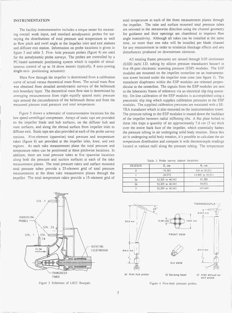
The facility instrumentation includes a torque meter for measur-ing overall work input, and standard aerodynamic probes for sur-veying the distributions of total pressure and temperature as wellas flow pitch and swirl angle at the impeller inlet and exit stationsand diffuser exit station. Information on probe locations is given infigure 3 and table 3. Five- hole pressure probes (figure 4) are usedfor the aerodynamic probe surveys. The probes are controlled by aPC-based automatic positioning system which is capable of simul-taneous control of up to 16 drive motors (typically, 8 auto-yawingsingle-axis- positioning actuators).
Mass flow through the impeller is determined from a calibrationcurve of actual versus theoretical mass flows. The actual mass flowwas obtained from detailed aerodynamic surveys of the bellmouthexit boundary layer. The theoretical mass flow rate is determined byaveraging measurements from eight equally spaced static pressuretaps around the circumference of the bellmouth throat and from themeasured plenum total pressure and total temperature.
Figure 5 shows a schematic of instrumentation locations for thelow speed centrifugal compressor. Arrays of static taps are providedon the impeller blade and hub surfaces, on the diffuser hub andvane surfaces, and along the shroud surface from impeller inlet todiffuser exit. Static taps are also provided at each of the probe survey
stations. Five-element (spanwise) total pressure and temperaturerakes (figure 6) are provided at the impeller inlet, knee, and exitregions. At each rake measurement plane the total pressure andtemperature rakes can be positioned at three pitchwise locations. Inaddition, there are total pressure tubes at five spanwise locationsalong both the pressure and suction surfaces at each of the rake
measurement planes. The total pressure rakes and surface mountedtotal pressure tubes provide a 25-element grid of total pressuremeasurements at the three rake measurement planes through theimpeller. The total temperature rakes provide a 15--element grid of
TOWERVV^L
total temperature at each of the three measurement planes throughthe impeller. The rake and surface mounted total pressure tubesare oriented in the streamwise direction using the channel geometryfor guidance and their openings are chamfered to improve flowangle insensitivity. Although all rakes can be installed at the sametime, no more than one rake will be installed per blade channelfor any measurement in order to minimize blockage effects and anydisturbances produced on downstream elements.
All rotating frame pressures are sensed through 0.05 centimeter(0.020 inch) I.D. tubing by silicon pressure transducers housed infive 48-port electronic scanning pressure (ESP) modules. The ESPmodules are mounted on the impeller centerline on an instrumenta-tion tower located under the impeller nose cone (see figure 3). Thetransducer diaphrams within the ESP modules are oriented perpen-dicular to the centerline. The signals from the ESP modules are sentto the laboratory frame of reference via an electrical slip ring assem-bly. On-line calibration of the ESP modules is accomplished using apneumatic slip ring which supplies calibration pressures to the ESPmodules. The supplied calibration pressures are measured with a SE-TRA transducer which is also mounted on the instrumentation tower.The pressure tubing to the ESP modules is routed down the backfaceof the impeller between radial stiffening ribs. A flat plate bolted tothese ribs traps a quantity of air approximately 7.6 cm (3 in) thickover the entire back face of the impeller, which essentially bathesthe pressure tubing in air undergoing solid body rotation. Since thisair is undergoing solid body rotadon, it's possible to calculate the airtemperature distribution and compare it with thermocouple readingslocated at various radii along the pressure tubing. The temperature
Table 3 Probe survey station locations.
STATION Z, cm R, cm
0 -76.581 0.0 to 43.511
1 -20.373 13.905 to 43.511
2a 32.205 to 46.543 81.280
2b 32.205 to 46.543 95.872
3 32.205 to 46.543 167.640
THERMOCOUPLE
9.652 mm
0.381 mm -#ro O 1.524 mm
I
FRONT VIEW
iI
914.4 mm
3/4 VIEW
vb) Sensing head c) Inlet shroud an
exit probe
Figure 3 Schematic of LSCC Ilowpath. Figure 4 Five--hole pressure probes.
5

SHROUD DIFFUSER VANEPASSAGE STATICS
SHROUD AND HUB DIFFUSERVANE PASSAGE STATICS
STATIC PRESSURETAP LOCATIONS.TYPICAL 10 PLANES
MERIDIONAL ROTORSECTION
SURPRO
CLEARANCEPROBE (^ILOCATIONS
IVINDOWS
ROTARY TABLE'
Z-SLIDE'
LASER VELOCIMETRY SYSTEM
20BLAD
SP
TOTAL PRESSURE ANDTEMPERATURE SURVEYMEASUREMENT POINTS
Figure 5 Low-speed centrifugal compressor instrumentation.
Figure 6 Rotating frame total pressure and total temperature rakes.
MEASUREMENT UNCER'T'AINTIES
Uncertainties determined for each of the primary and calculatedmeasurements are listed in table 4. In addition to providing uncer-tainty estimates for measured and calculated parameters, indicationsof the repeatability and circumferential uniformity of the flow fieldwhich can be expected from the low speed centrifugal compressorare provided. The repeatibility of the data provides assessment ofhow well flow conditions can be matched from test to test. Thedegree of circumferential uniformity of the flowfield is importantsince most steady-flow CFD codes require axisymmetric boundaryconditions. The normalized velocity profiles shown in figures 7 and8 were acquired at four different circumferential locations over a onemonth period. These results therefore provide an indication of therepeatability of the measurements as well as the degree of circum-ferential uniformity in the impeller inlet and exit flow field.
distribution along the pressure tubing is used to correct the measuredpressures for the centrifugal head effects due to the fluid in the pres-sure tubing between the static pressure measurement location andthe ESP pressure sensor port.
In addition to the above instrumentation, windows are providedover the impeller inlet, knee, and exit regions to allow for opticalaccess to the flow field (figure 5). The exit: window covers therotor trailing edge, the vaneless space, and the diffuser throat region.Laser anemometry and flow visualization are therefore possible. Theammonia-ozalid flow visualization technique will be used in boththe impeller and diffuser. Fluorescing oil, liquid crystal sheets, andtufts will also be used in the diffuser.
Table 4 Measurement uncertainties (95 % confidence interval).
Primary Nominal Percentmeasurement value uncertainty
Pressure 101325 NI .2 0.034Temperature 288 °K 0.4Swirl angle 70 deg 1.4Pitch angle 5 deg 3.0Position 13 cm 0.05
Calculated Nominal Percentmeasurement value uncertainty
Velocity 100 m/sec 025Mass flow rate 30 kg/sec 0.3Pressure ratio 1.13 0.042

l.z
V.
V 1fs
0.8
0.6
0.4
0.2
0'0 20 40 60 80 100
Shroud % Immersion Centerline
Figure 7 Circumferendal uniformity/repeatability of inlet flow field, Station 0.
0.7
V R/R t . 1.067
U 11%t
0 .6...___ ._.._.
4 1
3 2
0.5 Survey Quadrant
—G 1 1^1 2 V 3 ( 4
0.4' --0 20 40 60 80 100
SHROUD % Immersion HUB
Figure 8 Circumferential uniformity/repeatability ofimpeller exit flow field, SLabon 2a (4% tip clearance).
RESULTS AND DISCUSSION
The data presented herein consist of conventional aerodynamicprobe surveys upstream and downstream of the impeller, and flowvisualization results from fluorescing oil (Jurkovich et al., 1984).Results of computational analyses which support the experimentaldata are also presented. The main emphasis of the data and com-putational analysis presented herein is to illustrate the impact ofsynergism between experiments and computational analysis on thedevelopment of the low speed centrifugal compressor facility.
Research operating conditions selected for detailed investiga-tions of the low speed centrifugal compressor flow field were cho-sen to reflect design flow conditions (30 kg/sec) as well as high(36.36 kg/sec) and low (23.64 kg/sec) flow conditions. Because ofa problem with the facility temperature control, that has since beenfixed, and limitations on the maximum physical speed of the impeller(1950 rpm), the corrected speed for all research data was set at 97%of design speed (1862.4 rpm). Preliminary measurements indicatethat the impeller inlet boundary layer thickness measured at surveystation 1 is approximately 20% of span (5.921 cm) on the shroudand 2% of span (0.592 cm) on the hub.
Impact of Experiment/CFD Synergism
The history of the development of the low speed centrifugalcompressor illustrates how synergism between computational analy-ses and experimentation has affected the final design of the testhardware. The first research entry into the facility occurred Octo-ber 1, 1988, and due to a scheduled rehabilitation of the NASA
variable-frequency control facilities, testing was concluded Novem-ber 1, 1988. Since this was a new facility, the intent of the initialentry was to check out the research data acquisition system. Dur-ing the one month of operation preliminary surveys were acquiredupstream and downstream of the impeller. The data were not ana-lyzed in great detail, since the probes were uncalibrated and becauseseveral problems were uncovered with the data acquisition system.
About the same period of time, results of a computational anal-ysis of the compressor flow field by Moore and Moore (1989, 1990)of the Virginia Polytechnic Institute became available under a NASAgrant. This grant was initiated in the spirit of a cooperative effortto minimize the time typically required to develop a new facility.The Moore's calculated the LSCC flow field with their Elliptic FlowProgram, a 3—D pressure correction solution for discretized forms ofthe Navier-Stokes equations. The 3—D flow through the impeller wasmodelled using a 53 streamwise by 22 spanwise by 21 pitchwise grid.
The Moore's CFD solution indicated separation along the im-peller shroud wall near the impeller exit as shown in figure 9. Thisseparation continued downstream all the way to the outflow bound-ary condition which prevented the CFD solution from convergingsince the backflow within the separation region was bringing massflow into the solution domain across the out-flow boundary. In orderto obtain a converged solution, the Moore's altered the geometry inthe vaneless diffuser region, as shown in figure 10, to force the sep-arated flow region to close before it reached the outflow boundary.
About the same time the Moore's were generating their predic-tions of the LSCC flow field, NASA was also generating predic-tions of the flow field using the 3-D computational analyses of Hah(1988,1989) and Dawes (1988). These predictions also indicatedthat separation would occur along the impeller shroud. As a resultof these CFD predictions, the previously acquired preliminary ex-perimental results were investigated and were found to indicate aseverely retarded flow region near the shroud wall as shown in fig-ure 11. Although the preliminary measurements were inconclusivein substantiating the predicted shroud wall separation, the severelyretarded flow region measured near the shroud wall indicated thatshroud wall separation was probably imminent. Certainly, a reverseflow region within the tip clearance gap is expected, although thesurvey probe was not able to detect it. Since the rig was intendedfor fundamental flow physics research and CFD assessment, it wasconsidered undesirable to have separation which would affect theimpeller flow field and produce an undesirable downstream bound-ary condition for CFD analysis. Considering that the facility was
7

Flow ac mid—passage
.Prtjliiitittit
iii
inttt
lit
t^l
l1̂
R/R t • 1.067
° q 0 C.q
q q q q q
........................ _................... ..._.....................................
Preliminary Measurementswith Uncalibrated Probe
V 50r
im/s)40
30
20
10
tttrrrtlirtttilttttttttsttt'ttllttt
lrtrrtttilftrtt
ittlstttl
111tt^tt
^tittttt^
,rltlIllii
r^ l 1j
1l ^^f̂ , lJ
l̂ l^mfr
f
Figure 9 Meridional view of velocity vectors from Moore's (1988) 3-D flowcalculations of LSCC with 4% up clearance and constant height vaneless diffuser
fr
Figure 10 Meridional view of velocity vectors from Moore's (1988) 3-D flowcalculations of LSCC with 4% tip clearance and modified vaneless diffuser.
shutdown for a scheduled one year rehabilitation on November 1,1988, further investigation of the predicted shroud wall separationuntil after the shutdown was not possible. We decided therefore, thatthe best time to effect any modifications to the compressor geometry
would be during the facility shutdown.
Two potential modifications to the low speed centrifugal com-pressor were considered; 1) reduce the impeller exit tip clearance, 2)increase the vaneless diffuser area contraction. Reduction of the im-peller tip clearance was considered appropriate since the low speedcentrifugal compressor was initially designed with a uniform 4% exit
tip clearance which, although not atypical of industry practice (seetable 2 ), was on the high side. Before reducing the tip clearance, weasked industry for an opinion as to what level of tip clearance wouldbe most representative of typical operating conditions. Based on in-dustry response, we reduced the tip clearance to a circumferentiallyuniform level from inlet to exit of 2% based on the impeller exitblade span by bonding balsa wood strips to the tip of the impeller.In-house CFD analysis of the low speed centrifugal compressor with
0 20 40 60 80
100
SHROUD % IMMERSION
HUB
Figure 11 Radial velocity distribution atimpeller exit station 2a (4% up clearance).
8

i= 11/21 70.211a m/s
— R/Rtip = 1
— R/Rtip = 1
60
40
20Vr
(m/s)0
-20
` R/Rt - 1.067r _
CFD, mean---- CFD, min/maxq EXPERIMENT
-40^0
20 40 60 80
100SHROUD % Immersion
HUB
Figure 13 Radial velocity distribution atimpeller exit station 2a (2% tip clearance).
'r4111 1 ^'' ,^ ^ t , . , r
,^q^`^TTT T T ^
^ ,,r„
TT T T^
.rl}ti^ I '^ AI ^ '^ ^ ^ ^ \1.l
1R^. .!\
.rrlttiT^ T T T ^ ^ ^^^
,.^rr111
,.,rtttlTT T T I TTTTT
,.,rrttitTT T T T T TTTTT
,.,rrrttiTTT T t T T T TTTTT
,.,rirttiT^T T T T T TT TTTT
70.2114 m/s
Figure 12 Meridional view of velocity vectors predicted by the Dawes 3—D viscous flow calculation of the LSCC with 2% Lip clearance.
the reduced tip clearance was then initiated using the Dawes and Hahcodes to determine if a further modification to increase the vanelessdiffuser area contraction was necessary. At the same time the lowspeed centrifugal compressor was reinstalled in the facility and test-ing was initiated with the reduced tip clearance impeller. Hereafter,all references to the low speed centrifugal compressor will be forthe reduced tip clearance impeller.
Figure 12 shows a meridional view of velocity vectors at mid-pitch predicted by the Dawes code. The Dawes code was runwith a 107 streamwise by 41 spanwise by 21 pitchwise grid with 3control volumes in the clearance gap. The Dawes solution predictsseparation to occur on both the shroud and hub walls. A comparisonbetween the predicted and measured radial velocity profiles at theimpeller exit survey station, STA. 2a, is shown in figure 13 . Theexperimental results clearly do not indicate separation on either thehub or shroud surfaces as is predicted by the Dawes code. Sincethe Dawes code prediction showed that the hub separation began
very close to the experimental survey station and that the shroudseparation was confined to a thin layer, it seemed reasonable toexpect that the survey probe might not be able to detect the separationregions. As a result, it was decided to add a new aerodynamic surveylocation, STA. 2b, near the point at which the hub wall separationwas predicted to reach it's maximum thickness (i e., at R/R, _1.25S). In addition, flow tufts were taped to the laser window
9
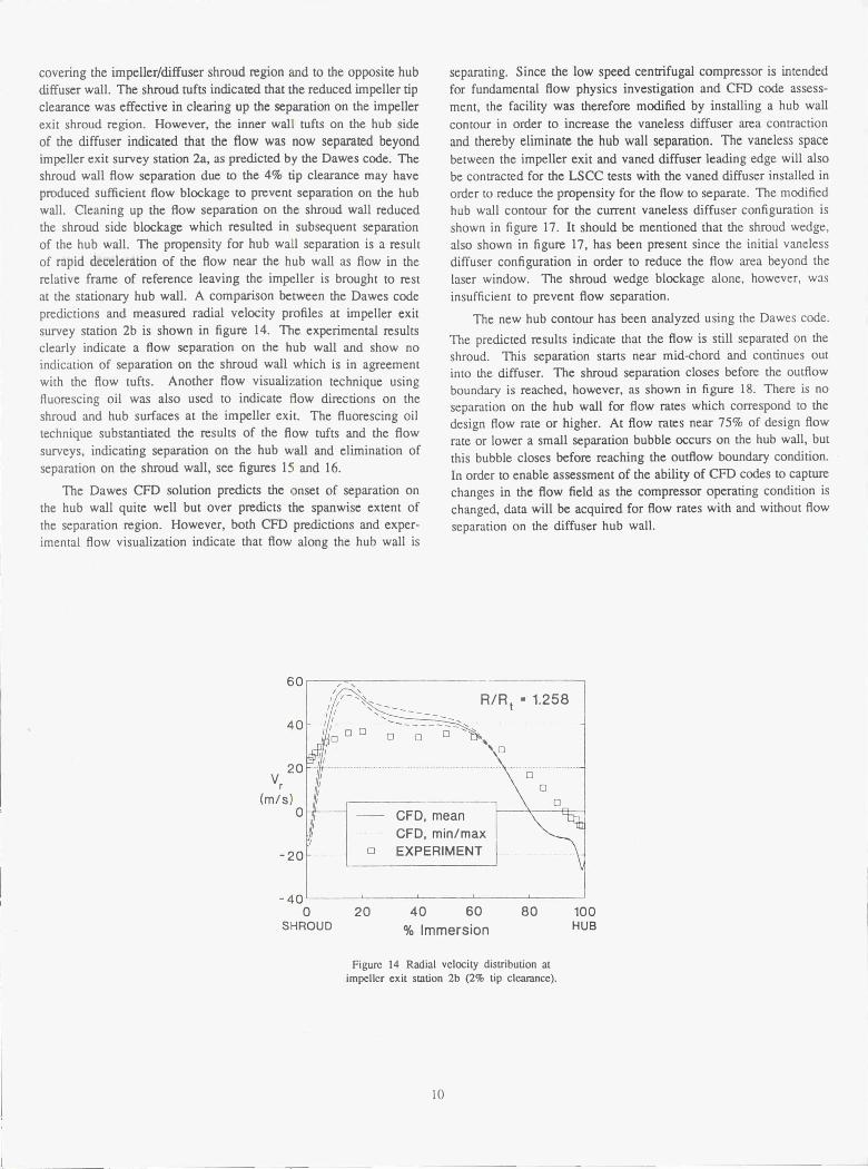
covering the impeller/diffuser shroud region and to the opposite hubdiffuser wall. The shroud tufts indicated that the reduced impeller tipclearance was effective in clearing up the separation on the impellerexit shroud region. However, the inner wall tufts on the hub sideof the diffuser indicated that the flow was now separated beyondimpeller exit survey station 2a, as predicted by the Dawes code. Theshroud wall flow separation due to the 4% tip clearance may haveproduced sufficient flow blockage to prevent separation on the hubwall. Cleaning up the flow separation on the shroud wall reducedthe shroud side blockage which resulted in subsequent separationof the hub wall. The propensity for hub wall separation is a resultof rapid deceleration of the flow near the hub wall as flow in therelative frame of reference leaving the impeller is brought to restat the stationary hub wall. A comparison between the Dawes codepredictions and measured radial velocity profiles at impeller exitsurvey station 2b is shown in figure 14. The experimental resultsclearly indicate a flow separation on the hub wall and show noindication of separation on the shroud wall which is in agreementwith the flow tufts. Another flow visualization technique usingfluorescing oil was also used to indicate flow directions on theshroud and hub surfaces at the impeller exit. The fluorescing oiltechnique substantiated the results of the flow tufts and the flowsurveys, indicating separation on the hub wall and elimination ofseparation on the shroud wall, see figures 15 and 16.
The Dawes CFD solution predicts the onset of separation onthe hub wall quite well but over predicts the spanwise extent ofthe separation region. However, both CFD predictions and exper-imental flow visualization indicate that flow along the hub wall is
separating. Since the low speed centrifugal compressor is intendedfor fundamental flow physics investigation and CFD code assess-ment, the facility was therefore modified by installing a hub wallcontour in order to increase the vaneless diffuser area contractionand thereby eliminate the hub wall separation. The vaneless spacebetween the impeller exit and vaned diffuser leading edge will alsobe contracted for the LSCC tests with the vaned diffuser installed inorder to reduce the propensity for the flow to separate. The modifiedhub wall contour for the current vaneless diffuser configuration isshown in figure 17. It should be mentioned that the shroud wedge,also shown in figure 17, has been present since the initial vanelessdiffuser configuration in order to reduce the flow area beyond thelaser window. The shroud wedge blockage alone, however, wasinsufficient to prevent flow separation.
The new hub contour has been analyzed using the Dawes code.
The predicted results indicate that the flow is still separated on theshroud. This separation starts near mid-chord and continues outinto the diffuser. The shroud separation closes before the outflowboundary is reached, however, as shown in figure 18. There is noseparation on the hub wall for flow rates which correspond to thedesign flow rate or higher. At flow rates near 75% of design flowrate or lower a small separation bubble occurs on the hub wall, butthis bubble closes before reaching the outflow boundary condition.In order to enable assessment of the ability of CFD codes to capturechanges in the flow field as the compressor operating condition ischanged, data will be acquired for flow rates with and without flowseparation on the diffuser hub wall.
60R/Rt - 1.258
40 1o qq \q q
q
V?0 _fi ..............................__..._ __...................................._.._...._--.o__....__..r q
(m/s) q0 CFD, mean
CFD, min/max
-20 -
q EXPERIMENT
-400 20 40 60 80
100
SHROUD % Immersion HUB
Figure 14 Radial velocity distribution atimpeller exit station 2b (2% tip clearance).
10
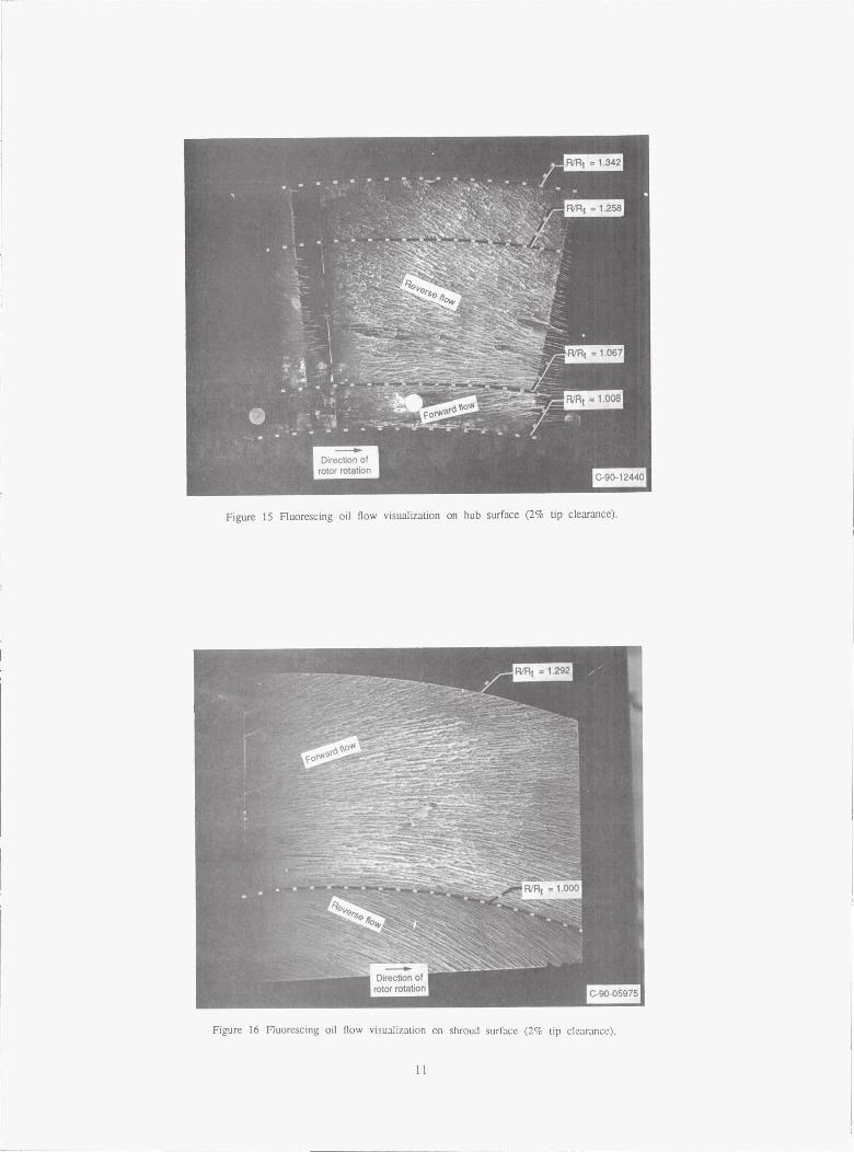
Figure 15 Fluorescing oil (low visualvabon on hub surface (2% tip clearance).
Figure 16 Fluorescing oil flow visualization on shroud surface (2% tip clearance).

STA. 3
I_150 Shroud
Location of
Wedge IVaned Diffuser
ModifiedR ^— Diffuser HubA 100 STA. 2bDI STA. 2aUS
(cm) STA.0 STA. 150
– Original vaned
jdiffuser design
-- Current vanelessdiffuser configuration
0r_
-100 -50 0 50 100 150AXIAL DISTANCE (cm)
Figure 17 Final flow path configuration showing modificationto diffuser hub contour in order to eliminate separation.
1 .258
1.067
i = 1 1/21 69.1264 m/s69.1264 m/s
Figure 18 Final solution of LSCC velocity field with modified diffuser hub contour and 2% tip clearance as predicted by Dawes 3—D viscous code.
TT T T R/Rtip =
TTT T T ^
TTTT T ^^^^^ITT T TTTTT^
^T ^^^TTTTT
,
rrTTTT T T ^ ^ ^ ^ ^ ^ ^'^^ ^`^R/Rtip =
'MW
N'tT T T TTTT
12

SUMMARY AND CONCLUSIONS
A new low speed centrifugal compressor facility for 3—D vis-cous code assessment and fundamental flow physics research hasbeen described. The facility is heavily instrumented with pressureand temperature probes, both in the rotating and stationary framesof reference, and has provisions for flow visualization and laser ve-locimetry. Preliminary measurements presented herein indicate thehigh quality of the data which can be expected from this facility.
The synergism between experimental data and computationalanalysis during the development of the LSCC has led to modifi-cations of compressor geometry which facilitate its use for funda-mental flow physics research and computational code assessment.Although the CFD models used for analysis of the LSCC flow fieldmay not have correctly predicted the magnitudes of the flow param-eters, they have been invaluable for capturing the essential featuresof the flow physics. The CFD results also provided useful guidancefor the experimental efforts to validate the CFD predictions.
ACKNOWLEDGMENTS
The authors would like to thank C. Hah and K. Kirtley for theircomputational analyses and T. Strazisar for his helpful suggestionsand assistance in preparing this paper.
REFERENCES
Dawes, W. N., 1988, "Development of a 3-D Navier StokesSolv er of Application to all Types of Turbomachinery," ASME Paper88-GT-70.
Dorney, D. J. and Davis, R. L., 1990, "Centrifugal CompressorImpeller Aerodynamics (A Numerical Investigation)," ASME Paper90—GT-213.
Eckardt, D., 1976, "Detailed Flow , Investigations within a High-Speed Centrifugal Compressor Impeller," Transactions of the ASME,Journal of Fluid Engineering, Vol. 98, No. 3, pp. 390-402.
Hah, C., Bryans, A. C., Moussa, Z. and Tomsho, M. E., 1988,"Application of Viscous Flow Computations for the AerodynamicPerformance of a Back-Swept Impeller at Various Operating Condi-tions," Transactions of the ASME, Journal of Turbomachinery, Vol.110, pp. 303-310.
Hah, C. and Krain, H., 1989, "Secondary Flows and VortexMotion in a High Efficiency Backswept Impeller at Design and Off-Design Conditions," Transactions of the ASME, Journal of Turbo-machinery, Vol. 112, No. 1, pp. 7-13.
Hayami, H., Senoo, Y. and Ueki, H., 1984, "Flow in the Inducerof a Centrifugal Compressor Measured with a Laser Velocimeter,"ASME Paper 84-GT-74.
Japiske, D. and Karon, D. M., 1989, "Laser Transit AnemometryInvestigation of a High Speed Centrifugal Compressor," ASMEPaper 89-GT-155.
Johnson, M_ W. and Moore, J., 1980, "The Development ofWake Flow in a Centrifugal Impeller," Transactions of the ASME,Journal of Engineering for Power, Vol. 102, No. 2, April, 1980.
Johnson, M. W. and Moore, J., 1983, "Secondary Flow MiringLosses in a Centrifugal Impeller," Transactions of the ASME, Journalof Engineering for Power, Vol. 105, No. 1, January, 1983.
Joslyn, H. D., Brasz, J. J., and Dring, R. P., 1990, "Centrifu-gal Compressor Impeller Aerodynamics (an Experimental Investiga-tion)," ASME Paper 90—GT-128.
Jurkovich, M. S., Greber, I., Hingst, W. R., "Flow VisualizationStudies of a 3—D Shock/Boundary Layer Interaction in the Pres-ence of a Non-Uniform Approach Boundary Layer," AIAA Paper84-1560.
Krain, H. and Hoffman, W., 1989, "Verification of an Im-peller Design by Laser Measurements and 3D-Viscous Calculations,"ASME Paper 89-GT-159.
Moore, J. and Moore, J. G., 1989, "A Prediction of 3—D ViscousFlow and Performance of the NASA Low-Speed Centrifugal Com-pressor," Virginia Polytechnic Institute and State University, Me-chanical Engineering Department, Turbomachinery Research Group,Report No. JM/89-1, January 1989.
Moore, J. and Moore, J. G., 1990, "A Prediction of 3-D Vis-cous Flow and Performance of the NASA Low-Speed CentrifugalCompressor," ASME Paper 90—GT-234.
Wood, J. R., Adam, P. W. and Buggele, A. E., 1983 "NASALow-Speed Centrifugal Compressor For Fundamental Research,"NASA TM 83398.
Young, M. Y., Spraker, W. A., and Struble, A. G., 1987, "Laser(L2F) Measurements at the Impeller Inlet and Tip Exit of a 91 mmTurbocharger Compressor," Third International Symposium on LaserAnemometry, ASME New York, 1987.
13

NASA Report Documentation PageNational Aeronautics andSpace Administration
1. Report No.NASA TM-103710
2. Government Accession No. 3. Recipient's Catalog No.
AVSCOM TR 91-C-003
4. Title and Subtitle 5. Report Date
NASA Low-Speed Centrifugal Compressor for 3-D ViscousCode Assessment and Fundamental Flow Physics Research —
6. Performing Organization Code
7. AUthor(s) 8. Performing Organization Report No.
M.D. Hathaway, J.R. Wood, and C.A. WasserbauerE-5938
10. Work Unit No.
505-62-21
_9. Performing Organization Name and Address
NASA Lewis Research Center IL161102AH45Cleveland, Ohio 44135-3191and
11. Contract or Grant No.
Propulsion DirectorateU.S. Army Aviation Systems CommandCleveland, Ohio 44135-3191 13. Type of Report and Period Covered
Technical Memorandum12. Sponsoring Agency Name and Address
National Aeronautics and Space AdministrationWashington, D.C. 20546-0001 14. Sponsoring Agency CodeandU.S. Army Aviation Systems CommandSt. Louis, Mo. 63120-1798
15. Supplementary Notes
Prepared for the 36th International Gas Turbine and Aeroengine Congress and Exposition sponsored by the American Society ofMechanical Engineers, Orlando, Florida, June 3-6, 1991. M.D. Hathaway, Propulsion Directorate, U.S. Army Aviation SystemsCommand. J.R. Wood, NASA Lewis Research Center. C.A. Wasserbauer. Sverdrup Technology, Inc., Lewis Research CenterGroup, 2001 Aerospace Parkway, Brook Park, Ohio 44142. Responsible person, M.D. Hathaway, (216) 433-6250.
16. Abstract
A low speed centrifugal compressor facility recently built by the NASA Lewis Research Center is described. Thepurpose of this facility is to obtain detailed Flow field measurements for computational fluid dynamic codeassessment and flow physics modelling in support of Army and NASA efforts to advance small gas turbineengine technology. The facility is heavily instrumented with pressure and temperature probes, both in thestationary and rotating frames of reference, and has provisions for flow visualization and laser velocimetry. Thefacility will accommodate rotational speeds to 2400 rpm and is rated at pressures to 1.25 atm. The initialcompressor stage being tested is geometrically and dynamically representative of modern high-performancecentrifugal compressor stages with the exception of Mach number levels. Preliminary experimental investigationsof inlet and exit flow uniformity and measurement repeatability are presented. These results demonstrate the highquality of the data which may be expected from this facility. The significance of synergism between computa-tional fluid dynamic analyses and experimentation throughout the development of the low speed centrifugalcompressor facility is demonstrated.
17. Key Words (Suggested by Author(s)) 18. Distribution Statement
Centrifugal compressor Unclassified - Unlimited
Low speed Subject Category 02ExperimentComputation
19. Security Classif. (of this report) 20. Security Classif. (of this page) 21. No. of pages 22. Price'
Unclassified Unclassified 14 A03
NASA FORM 1626 OCT 86 • For sale by the National Technical Information Service, Springfield, Virginia 22161