N9321C Basic Spectrum Analyzer - farnell.com
20
Find us at www.keysight.com Page 1 N9321C Basic Spectrum Analyzer 9 kHz to 4 GHz
Transcript of N9321C Basic Spectrum Analyzer - farnell.com
Find us at www.keysight.com Page 1
N9321C Basic Spectrum Analyzer 9 kHz to 4 GHz

Find us at www.keysight.com Page 2
Definitions and Conditions Specification Describes the performance of parameters covered by the product warranty and apply to the full temperature range of 5 to 45 °C, unless otherwise noted.
Typical Describes additional product performance information that is not covered by the product warranty. It is performance beyond specifications that 80 percent of the units exhibit with a 95 percent confidence level over the temperature range 20 to 30 °C. This data does not include measurement uncertainty.
Nominal Indicates expected performance or describe product performance that is useful in the application of the product but are not covered by the product warranty.
The analyzer will meet its specifications when:
• It is within its calibration cycle • It has been turned on at least 30 minutes • It has been stored at an ambient temperature within the allowed operating range for at least
two hours before being turned on; if it had previously been stored at a temperature range inside the allowed storage, but outside the allowed operating range

Find us at www.keysight.com Page 3
Frequency and Time Specifications
Supplemental information
Frequency
Range 9 kHz to 4 GHz AC coupled
Resolution 1 Hz
Frequency reference
Option PFR Standard
Nominal frequency 10 MHz 10 MHz
Aging rate ± 1 × 10⁻⁷/Year ± 1 × 10⁻⁶/Year
Temperature stability
20 °C to 30 °C ± 1.5 × 10⁻⁸
5 °C to 45 °C ± 5 × 10⁻⁸ ± 1 × 10⁻⁶
Achievable initial calibration accuracy ± 4 × 10⁻⁸ ± 1 × 10⁻⁶
Frequency readout accuracy (start, stop, center, marker)
Marker resolution (frequency span)/(number of sweep point -1)
Uncertainty ± (freq indication × freq reference uncertainty 1 + 1% × span + 20% × resolution bandwidth + marker resolution + 1 Hz)
Sweep point 461, fixed
Marker frequency counter
Resolution 1 Hz
Accuracy ± [(marker freq × freq reference uncertainty 1) + (counter resolution)]
RBW/Span ≥ 0.02 Marker level to displayed noise level > 25 dB, frequency offset = 0 Hz
1. F requency refe rence uncerta in ty = Aging rate x pe riod since ad jus tmen t + tempera tu re s tab il i ty .
Find us at www.keysight.com Page 4
Supplemental information
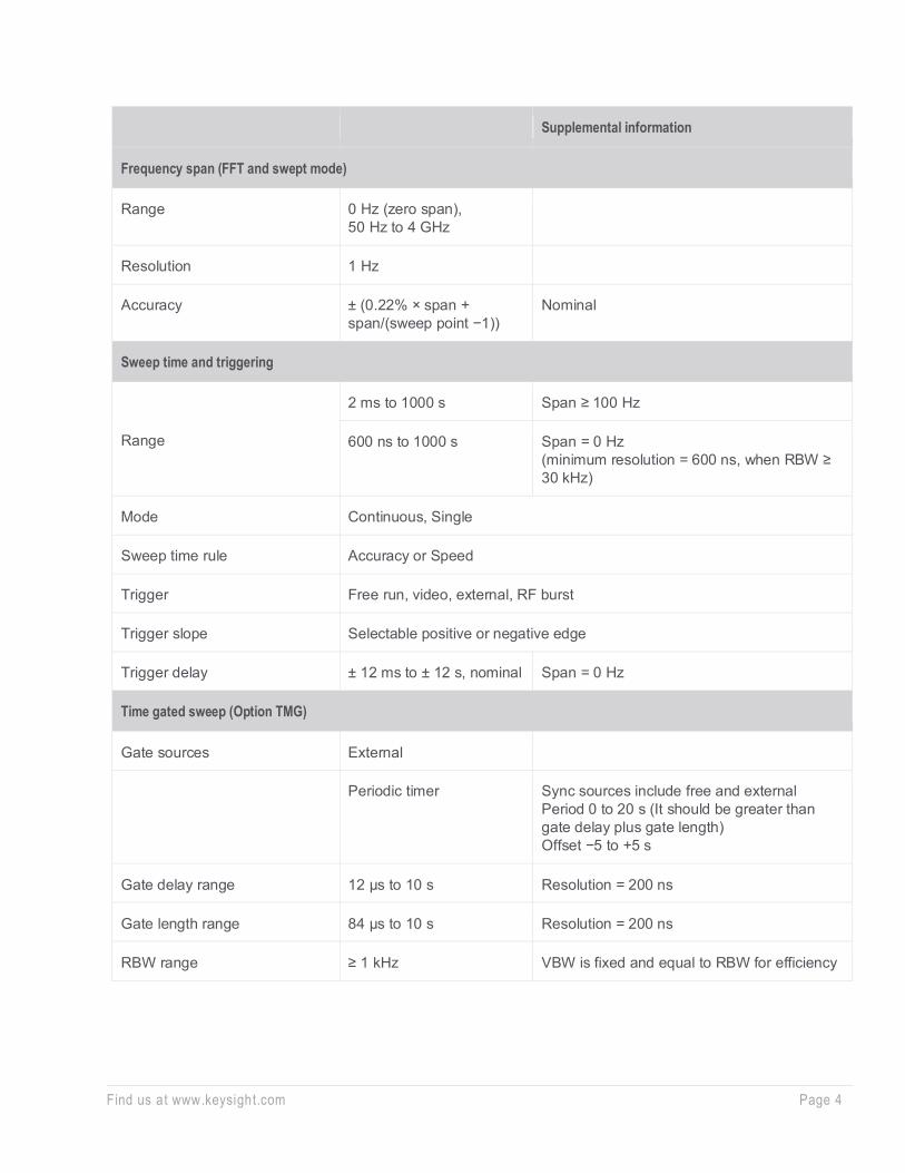
Frequency span (FFT and swept mode)
Range 0 Hz (zero span), 50 Hz to 4 GHz
Resolution 1 Hz
Accuracy ± (0.22% × span + span/(sweep point −1))
Nominal
Sweep time and triggering
Range
2 ms to 1000 s Span ≥ 100 Hz
600 ns to 1000 s Span = 0 Hz (minimum resolution = 600 ns, when RBW ≥ 30 kHz)
Mode Continuous, Single
Sweep time rule Accuracy or Speed
Trigger Free run, video, external, RF burst
Trigger slope Selectable positive or negative edge
Trigger delay ± 12 ms to ± 12 s, nominal Span = 0 Hz
Time gated sweep (Option TMG)
Gate sources External
Periodic timer Sync sources include free and external Period 0 to 20 s (It should be greater than gate delay plus gate length) Offset −5 to +5 s
Gate delay range 12 μs to 10 s Resolution = 200 ns
Gate length range 84 μs to 10 s Resolution = 200 ns
RBW range ≥ 1 kHz VBW is fixed and equal to RBW for efficiency

Find us at www.keysight.com Page 5
Supplemental information
Resolution bandwidth (RBW)
Range (-3 dB bandwidth) 10 Hz to 3 MHz In 1-3-10 sequence
Accuracy ± 5%, nominal < 10% when RBW = 3 MHz
Resolution filter shape factor < 5:1, nominal 60 dB/3 dB bandwidth ratio, digital, Gaussian-like
EMI bandwidth (CISPR compliant) 200 Hz, 9 kHz, 120 kHz, 1 MHz Option EMC required
Accuracy ± 10%, nominal
Resolution filter shape factor < 5:1, nominal -60 dB/-6 dB bandwidth ratio
Video bandwidth (VBW)
Range 1 Hz to 3 MHz In 1-3-10 sequence
Accuracy ± 10%, nominal VBW = 1 Hz to 1 MHz

Find us at www.keysight.com Page 6
Amplitude Specifications
Supplemental information
Measurement range
100 kHz to 1 MHz Displayed average noise level (DANL) to +10 dBm Preamp off
1 MHz to 4 GHz Displayed average noise level (DANL) to +20 dBm
Input attenuator range 0 to 50 dB, in 1 dB steps
Maximum damage level
Average continuous power +33 dBm, 3 minutes maximum Input attn ≥ 20 dB, 2 MHz to 4 GHz
DC voltage ± 50 VDC maximum
Level display range
Scale units dBm, dBmV, dBμV, W, V, dBmV EMF, dBμV EMF, V EMF
Marker level readout 0.01 dB Log scale
Resolution < 1% of signal level Linear scale
Number of traces 4
Detectors Normal, positive peak, sample, negative peak, average (video, RMS, voltage), quasi-peak (option EMC required)
Trace function Clear/write, maximum hold, minimum hold, average
Frequency response
20 to 30°C, 30% to 70% relative humidity, attenuation 20 dB, reference frequency 50 MHz
9 to 100 kHz ± 0.5 dB nominal Preamp off
100 kHz to 3 GHz ± 0.7 dB Preamp off
3 to 4 GHz ± 0.85 dB Preamp off
100 kHz to 3 GHz ± 0.7 dB Preamp on
3 to 4 GHz ± 0.9 dB Preamp on

Find us at www.keysight.com Page 7
Supplemental information
Input attenuation switching uncertainty at 50 MHz
1 to 50 dB attenuation ± 0.2 dB, typical Relative to 20 dB reference setting
Resolution bandwidth switching uncertainty
10 Hz to 3 MHz RBW +0.1 dB, nominal
Total absolute amplitude accuracy
20 to 30 °C, 30% to 70% RH, peak detector, RBW 1 kHz, VBW 300 Hz, sweep time Accuracy, input signal −50 to 0 dBm, preamp off, attenuation 20 dB. Add additional ± 0.3 dB when sweep time rule is set to Speed
At 50 MHz ± 0.3 dB
At all frequencies ± (0.3 dB + frequency response)
100 kHz to 3 GHz ± 0.60 dB 95th percentile
3 to 4 GHz ± 0.65 dB 95th percentile
Preamp on
At 50 MHz ± 0.4 dB
At all frequencies ± (0.4 dB + frequency response)
100 kHz to 3 GHz ± 0.60 dB 95th percentile
3 to 4 GHz ± 0.65 dB 95th percentile
Preamplifier (Option P04)
Frequency range 9 kHz to 4 GHz
Gain 25 dB, nominal 100 kHz to 4 GHz
15 dB, nominal 9 to 100 kHz

Find us at www.keysight.com Page 8
Dynamic Range Specifications
1 dB gain compression
20 to 30°C, frequency ≥ 50 MHz, Ref level > −20 dBm, nominal Mixer power level (dBm) = input power (dBm) − input attenuation (dB) when preamp off Total power at the preamp = total power at the input (dBm) − input attenuation (dB) when preamp on
Preamp off 50 to 200 MHz +2 dBm
200 to 500 MHz +4 dBm
500 MHz to 4 GHz +7 dBm
Preamp on > -32 dBm, total power at the preamp
Displayed average noise level Normalized to 1 Hz Minimum RBW
20 to 30 °C, input terminated 50 Ω, 0 dB input attenuation, RBW = 1 kHz, RMS detector, average ≥ 40
Preamp off 9 to 100 kHz -100 dBm, nominal -90 dBm, nominal
100 kHz to 1 MHz -108 dBm, typical -127 dBm -98 dBm, typical -117 dBm
1 to 10 MHz -128 dBm, typical -146 dBm -118 dBm, typical -136 dBm
10 to 500 MHz -142 dBm, typical -146 dBm -132 dBm, typical -136 dBm
500 MHz to 2.5 GHz -141 dBm, typical -145 dBm -131 dBm, typical -135 dBm
2.5 to 4 GHz -140 dBm, typical -144 dBm -130 dBm, typical -134 dBm
Preamp on 9 to 100 kHz -110 dBm, nominal -100 dBm, nominal
100 kHz to 1 MHz -131 dBm, typical -150 dBm -121 dBm, typical -140 dBm
1 to 10 MHz -148 dBm, typical -163 dBm -138 dBm, typical -153 dBm
10 to 500 MHz -161 dBm, typical -164 dBm -151 dBm, typical -154 dBm
500 MHz to 2.5 GHz -159 dBm, typical -162 dBm -149 dBm, typical -152 dBm
2.5 to 4 GHz -158 dBm, typical -161 dBm -148 dBm, typical -151 dBm

Find us at www.keysight.com Page 9
Spurious response
Input terminated and 0 dB input attenuation, preamp off 20 to 30 °C
Residual response < −90 dBm, typical −98 dBm
−30 dBm signal at input mixer 20 to 30 °C
Input related spurious < −75 dBc
Exceptions:
−65 dBc (F1 - 21.4 MHz, with F1 input frequency)
−65 dBc (F1 - 5.35 MHz, with F1 input frequency)
Mixer signal level at −30 dBm, input attenuation 0 dB, preamp off, 20 to 30 °C
Second harmonic distortion 50 MHz to 3 GHz < −65 dBc
3 to 4 GHz < −70 dBc
Two −20 dBm tones at input mixer, spaced by 100 kHz, input attenuation 0 dB, preamp off, reference level > −20 dBm, 20 to 30 °C
Third order intermodulation distortion (third order intercept)
50 to 300 MHz +9 dBm, typical +12 dBm
300 MHz to 4 GHz +11 dBm, typical +15 dBm
Phase noise
20 to 30 °C, center frequency = 1 GHz
Offset from CF signal 10 kHz Typical −90 dBc/Hz
100 kHz −98 dBc/Hz, typical −100 dBc/Hz
1 MHz −119 dBc/Hz, typical −121 dBc/Hz
Residual FM
20 to 30 °C, RBW 100 Hz ≤ 10 Hz p–p in 20 ms, nominal
Find us at www.keysight.com Page 10
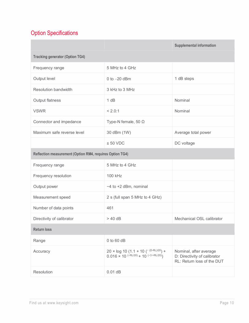
Option Specifications
Supplemental information
Tracking generator (Option TG4)
Frequency range 5 MHz to 4 GHz
Output level 0 to −20 dBm 1 dB steps
Resolution bandwidth 3 kHz to 3 MHz
Output flatness 1 dB Nominal
VSWR < 2.0:1 Nominal
Connector and impedance Type-N female, 50 Ω
Maximum safe reverse level 30 dBm (1W) Average total power
± 50 VDC DC voltage
Reflection measurement (Option RM4, requires Option TG4)
Frequency range 5 MHz to 4 GHz
Frequency resolution 100 kHz
Output power −4 to +2 dBm, nominal
Measurement speed 2 s (full span 5 MHz to 4 GHz)
Number of data points 461
Directivity of calibrator > 40 dB Mechanical OSL calibrator
Return loss
Range 0 to 60 dB
Accuracy 20 × log 10 (1.1 + 10 (− (D-RL)/20) + 0.016 × 10 (−RL/20) + 10 (−3 +RL/20))
Nominal, after average D: Directivity of calibrator RL: Return loss of the DUT
Resolution 0.01 dB

Find us at www.keysight.com Page 11
Supplemental information
Voltage standing wave ratio
Range 1 to 65
Resolution 0.01
Accuracy Refer to return loss accuracy
Insertion loss
Range 0 to 30 dB
Resolution 0.01 dB
Distance-to-fault (DTF)
Vertical range 0 to 60 dB Return loss
1 to 65 VSWR
Range (Number of data points − 1) × resolution
Number of data points = 461
Resolution (meter) (1.5 × 10⁸) × (VP)/(F2 - F1) Hz VP is the cable's relative propagation velocity F2 is the stop frequency F1 is the start frequency
Immunity to interface
On-channel +17 dBm Nominal
On-frequency −5 dBm Nominal
AM/FM modulation analysis (Option AMA)
Frequency range 10 MHz to 4 GHz
Carrier power accuracy ± 1.8 dB Nominal
Carrier power range –30 to +10 dBm 100 kHz to 2 MHz
–30 to +20 dBm 2 MHz to 4 GHz

Find us at www.keysight.com Page 12
Supplemental information
AM measurement (included in Option AMA)
Modulation rate 20 Hz to 100 kHz
Accuracy 1 Hz Nominal (modulation rate < 1 kHz)
< 0.1% modulation rate Nominal (modulation rate > 1 kHz)
Depth 5 to 95%
Accuracy ± 4% Nominal
FM measurement (included in Option AMA)
Modulation rate 20 Hz to 200 kHz
Accuracy 1 Hz Nominal (modulation rate < 1 kHz)
< 0.1% modulation rate Nominal (modulation rate > 1 kHz)
Deviation 20 Hz to 400 kHz
Accuracy ± 4% Nominal
ASK/FSK modulation analysis (Option DMA)
Frequency range 2.5 MHz to 4 GHz
Carrier power accuracy ± 2 dB Nominal
Carrier power range −30 to +20 dBm Nominal
Carrier power displayed resolution 0.01 dBm
ASK measurement (included in Option DMA)
Symbol rate range 100 Hz to 100 kHz
Modulation depth/index 5 to 95%
Accuracy ± 4% Nominal
Displayed resolution 0.1%
Find us at www.keysight.com Page 13
Supplemental information
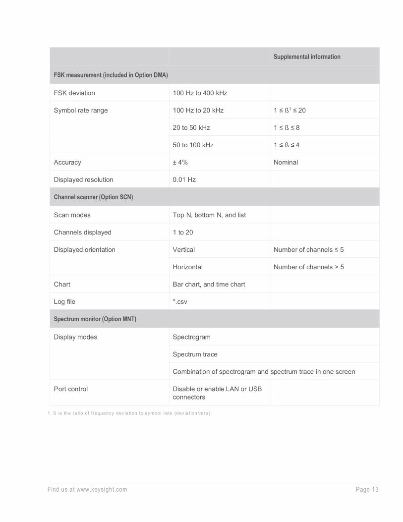
FSK measurement (included in Option DMA)
FSK deviation 100 Hz to 400 kHz
Symbol rate range 100 Hz to 20 kHz 1 ≤ ß1 ≤ 20
20 to 50 kHz 1 ≤ ß ≤ 8
50 to 100 kHz 1 ≤ ß ≤ 4
Accuracy ± 4% Nominal
Displayed resolution 0.01 Hz
Channel scanner (Option SCN)
Scan modes Top N, bottom N, and list
Channels displayed 1 to 20
Displayed orientation Vertical Number of channels ≤ 5
Horizontal Number of channels > 5
Chart Bar chart, and time chart
Log file *.csv
Spectrum monitor (Option MNT)
Display modes Spectrogram
Spectrum trace
Combination of spectrogram and spectrum trace in one screen
Port control Disable or enable LAN or USB connectors
1. ß is the ra t io of frequency dev ia tion to symbol ra te (dev ia t ion /ra te ).
Find us at www.keysight.com Page 14
Supplemental information
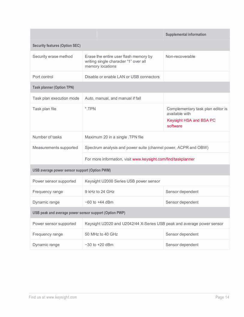
Security features (Option SEC)
Security erase method Erase the entire user flash memory by writing single character “1” over all memory locations
Non-recoverable
Port control Disable or enable LAN or USB connectors
Task planner (Option TPN)
Task plan execution mode Auto, manual, and manual if fail
Task plan file *.TPN Complementary task plan editor is available with Keysight HSA and BSA PC software
Number of tasks Maximum 20 in a single .TPN file
Measurements supported Spectrum analysis and power suite (channel power, ACPR and OBW)
For more information, visit www.keysight.com/find/taskplanner
USB average power sensor support (Option PWM)
Power sensor supported Keysight U2000 Series USB power sensor
Frequency range 9 kHz to 24 GHz Sensor dependent
Dynamic range −60 to +44 dBm Sensor dependent
USB peak and average power sensor support (Option PWP)
Power sensor supported Keysight U2020 and U2042/44 X-Series USB peak and average power sensor
Frequency range 50 MHz to 40 GHz Sensor dependent
Dynamic range −30 to +20 dBm Sensor dependent

Find us at www.keysight.com Page 15
Supplemental information
Base band input (Option BB1)
Frequency range 9 kHz to 10 MHz
Frequency span 100 kHz to 9.997 MHz
Frequency resolution 1 Hz
Measurement ranged DANL to +10 dBm (9 kHz to 2 MHz)
DANL to +20 dBm (2 MHz to 10 MHz)
Overall amplitude accuracy
20 to 30°C, 30 to 70% RH, peak detector, input signal −50 to 0 dBm, 95th percentile
9 to 100 kHz ± 2.5 dB
100 kHz to 10 MHz ± 1.5 dB
Displayed average noise level
20 to 30 °C, 30 to 70% RH, 10 Hz RBW, 1 Hz VBW, 50 Ω termination on input, 0 dB attenuation, RMS detector, Trace average > 40, reference level < −35 dBm
9 to 100 kHz −135 dBm Nominal
100 kHz to 10 MHz −145 dBm
Phase noise
Fc = 5 MHz, RBW = 1 kHz, VBW = 30 Hz. Ref level −30 dBm, input attenuation 0 dB, input signal −20 dBm, average > 40
Offset 30 kHz −120 dBc/Hz Nominal
Offset 100 kHz −127 dBc/Hz Nominal
Offset > 200 kHz −130 dBc/Hz Nominal

Find us at www.keysight.com Page 16
Supplemental information
Base band input (Option BB1, continued)
Residual response
< −120 dBm, nominal 20 to 30°C, Ref level < −35 dBm 50 Ω termination on input 0 dB attenuation
Second harmonic distortion
< −55 dBc nominal F > 100 kHz Signal level −30 dBm Ref level −30 dBm Attenuation 0 dB
Third order intermodulation distortion
< −55 dBc, nominal F > 100 kHz −20 dBm tones at 100 kHz apart Ref level −20 dBm Attenuation 0 dB

Find us at www.keysight.com Page 17
Inputs and Outputs
Front panel
RF input connector N-type female, 50 Ω, nominal
VSWR 10 MHz to 3 GHz < 1.5:1, nominal, ≥ 10 dB attenuation
3 to 4 GHz < 2.0:1, nominal, ≥ 10 dB attenuation
Calibration output Amplitude −25 ± 0.25 dBm
Frequency 40 MHz
Connector and impedance BNC-type female, 50 Ω, nominal
Probe power Voltage/Current +15 V, 150 mA maximum
−12.6 V, 150 mA maximum
RF output connector N-type female, 50 Ω, nominal Option TG4 installed
USB interface (host) A plug, version 1.1
Rear panel
10 MHz reference output Output amplitude > 0 dBm
Frequency 10 MHz ± (10 MHz × frequency reference accuracy)
Connector and impedance BNC-type female, 50 Ω, nominal
10 MHz reference input Input amplitude –5 to +10 dBm, nominal
Frequency 10 MHz
Connector and impedance BNC-type female, 50 Ω, nominal
External trigger input Input amplitude 5 V TTL level, −12.6 V, 150 mA max (nominal)
Connector and impedance BNC-type female, 10 k Ω
LAN TCP/IP interface 100Base-T, RJ-45 connector
USB interface (device) B plug, version 1.1
Mini USB (device) Mini-AB female, version 1.1
GPIB interface IEEE-488 bus connector Optional G01 installed
Find us at www.keysight.com Page 18
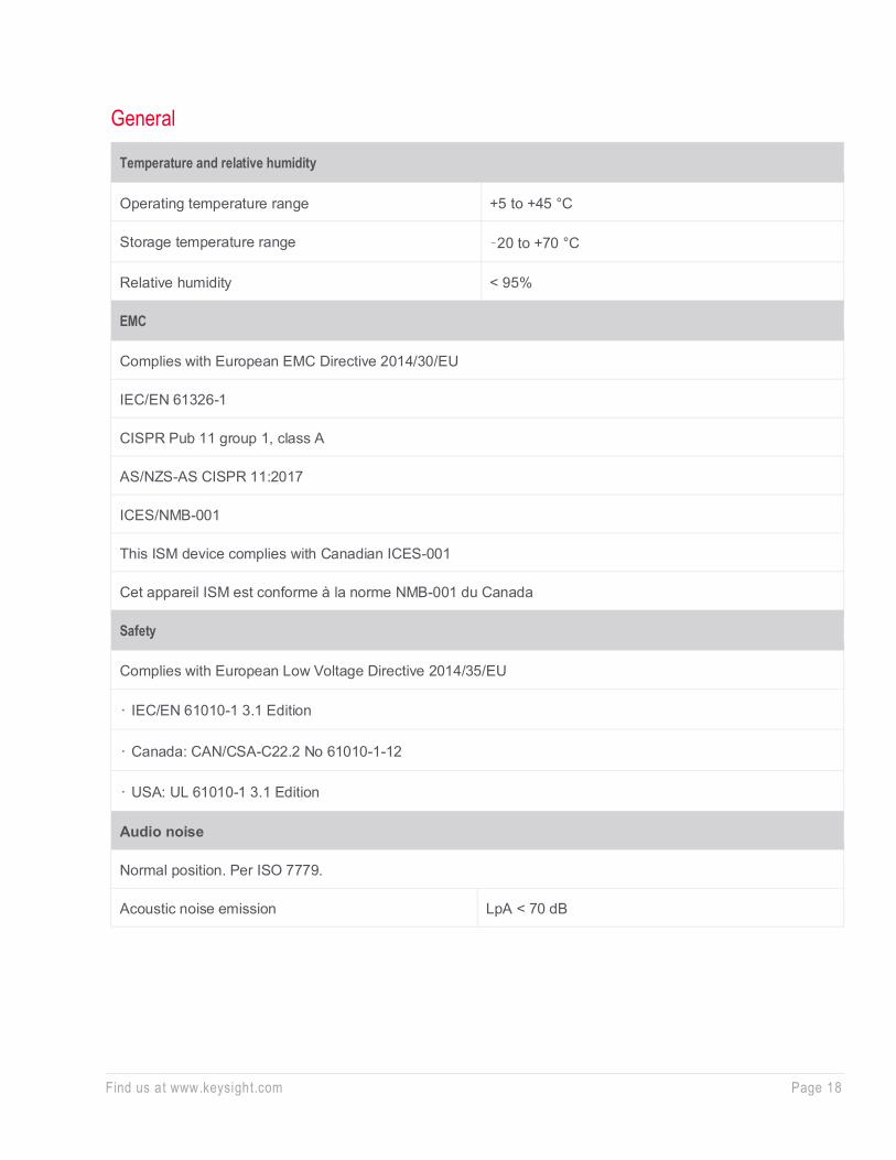
General
Temperature and relative humidity
Operating temperature range +5 to +45 °C
Storage temperature range –20 to +70 °C
Relative humidity < 95%
EMC
Complies with European EMC Directive 2014/30/EU
IEC/EN 61326-1
CISPR Pub 11 group 1, class A
AS/NZS-AS CISPR 11:2017
ICES/NMB-001
This ISM device complies with Canadian ICES-001
Cet appareil ISM est conforme à la norme NMB-001 du Canada
Safety
Complies with European Low Voltage Directive 2014/35/EU
• IEC/EN 61010-1 3.1 Edition
• Canada: CAN/CSA-C22.2 No 61010-1-12
• USA: UL 61010-1 3.1 Edition
Audio noise
Normal position. Per ISO 7779.
Acoustic noise emission LpA < 70 dB

Find us at www.keysight.com Page 19
Environmental stress
Samples of this product have been type tested in accordance with the Keysight Environmental Test Manual and verified to be robust against the environmental stresses of storage, transportation, and end-use; those stresses include, but are not limited to, temperature, humidity, shock, vibration, altitude, and power line conditions. Test methods are aligned with IEC 60068-2 and levels are similar to MILPRF-28800F Class 3
Power requirements
Voltage and frequency (nominal) 100 to 240 VAC, 50 to 60 Hz, Auto ranging
Power consumption ≤ 25 W, < 20 W, typical
Display
Resolution 640 x 480
Size 165.1 mm (6.5 inch) diagonal (nominal)
Data storage
Internal 64 MB nominal
External Supports USB 3.0 compatible memory devices
Weight (without options)
Net 7.9 kg (17.4 lbs), nominal
Shipping 14.5 kg (30.9 lbs), nominal

Find us at www.keysight.com Page 20 This information is subject to change without notice. © Keysight Technologies, 2021, Published in USA, July 22, 2021, 3121-1285.EN
Learn more at: www.keysight.com For more information on Keysight Technologies’ products, applications or services, please contact your local Keysight office. The complete list is available at: www.keysight.com/find/contactus
Dimensions
Height 132.5 mm (5.2 inch)
Width 320 mm (12.6 inch)
Length 400 mm (15.7 inch)
Warranty
The N9321C spectrum analyzer is supplied with a five-year warranty
Calibration cycle
The recommended calibration cycle is one year. Calibration services are available through Keysight service centers