MX2800 M13 Multiplexer User Manual - Cutter Networks
200
MX2800 M13 Multiplexer User Manual Manual Part Number - 61200290L1-1G 4205290L1 AC Non-Redundant Version with Modem 4205290L2 AC Redundant Version with Modem 4205290L3 DC Non-Redundant Version with Modem 4205290L4 DC Redundant Version with Modem 4205290L5 AC Non-Redundant Version 4205290L6 AC Redundant Version 4205290L7 DC Non-Redundant Version 4205290L8 DC Redundant Version 1205288L1 Controller Card 1205288L2 Controller Card 1200291L1 Breakout Panel 4175043L2 Battery Backup 1200657L2 Battery Backup Adapter Cable 1200287L1 Amp to Punch-Down Cable 25 ft. 1200287L5 Amp to Punch-Down Cable 50 ft. 1200287L7 Amp to Punch-Down Cable 100 ft. 1200291L5 BNC patch panel 1200466L1 Fan Faceplate 61200290L1-1G October 2004
Transcript of MX2800 M13 Multiplexer User Manual - Cutter Networks
MX2800 M13 MultiplexerUser Manual
Manual Part Number - 61200290L1-1G
4205290L1 AC Non-Redundant Version with Modem4205290L2 AC Redundant Version with Modem4205290L3 DC Non-Redundant Version with Modem4205290L4 DC Redundant Version with Modem4205290L5 AC Non-Redundant Version4205290L6 AC Redundant Version4205290L7 DC Non-Redundant Version4205290L8 DC Redundant Version1205288L1 Controller Card1205288L2 Controller Card1200291L1 Breakout Panel4175043L2 Battery Backup1200657L2 Battery Backup Adapter Cable1200287L1 Amp to Punch-Down Cable 25 ft.1200287L5 Amp to Punch-Down Cable 50 ft.1200287L7 Amp to Punch-Down Cable 100 ft.1200291L5 BNC patch panel1200466L1 Fan Faceplate
®
61200290L1-1GOctober 2004
®

MX2800 M13 Multiplexer System Manual
TrademarksAny brand names and product names included in this manual are trademarks, registered trademarks, or trade names of their respective holders.
OpenView™ is a trademark of Hewlett-Packard Company.
Spectrum® is a registered trademark of Cabletron.
ADVISION™ is a trademark of ADTRAN.
Total Access Element Management System™ is a trademark of ADTRAN.
To the Holder of the ManualThe contents of this manual are current as of the date of publication. ADTRAN® reserves the right to change the contents without prior notice.
In no event will ADTRAN be liable for any special, incidental, or consequential damages or for commercial losses even if ADTRAN has been advised thereof as a result of issue of this publication.
901 Explorer BoulevardP.O. Box 140000
Huntsville, AL 35814-4000(256) 963-8000
©2004 ADTRAN, Inc.All Rights Reserved.
Printed in U.S.A.
®®
ii 61200290L1-1G

MX2800 M13 Multiplexer System Manual
Revision History
ConventionsThe following typographical conventions are used in this document:
This font indicates a cross-reference link. First-time references to tables and figures are shown in this font.
This font indicates screen menus, fields, and parameters.
THIS FONT indicates keyboard keys (ENTER, ESC, ALT). Keys that are to be pressed simulta-neously are shown with a plus sign (ALT+X indicates that the ALT key and X key should be pressed at the same time).
This font indicates references to other documentation, sections of documents, and is also used for emphasis.
This font indicates on-screen messages and prompts.
This font indicates text to be typed exactly as shown.
This font indicates silkscreen labels or other system label items.
This font is used for strong emphasis
NOTENotes inform the user of additional but essential information or features.
CAUTIONCautions inform the user of potential damage, malfunction, or disruptionto equipment, software, or environment.
WARNINGWarnings inform the user of potential bodily pain, injury, or death.
DocumentRevision Date Description of Changes
G Oct. 2004 This revision of the MX2800 M13 Multiplexer User Manual has been updated to include new features for the System Control Unit (P/N 1185002L2).
61200290L1-1G iii

MX2800 M13 Multiplexer System Manual
FCC Radio Frequency Interference StatementThis equipment has been tested and found to comply with the limits for a Class A digital device, pursuant to Part 15 of the FCC Rules. These limits are designed to provide reasonable protection against harmful interference when the equipment is operated in a commercial environment. This equipment generates, uses, and can radiate radio frequency energy and, if not installed and used in accordance with the instruction manual, may cause harmful interference to radio frequencies. Operation of this equipment in a residential area is likely to cause harmful interference in which case the user will be required to correct the interference at his own expense.
NOTEShielded cables must be used with this unit to ensure compliance withClass A FCC limits.
CAUTIONChanges or modifications to this unit not expressly approved by the partyresponsible for compliance could void the user’s authority to operate theequipment.
Canadian Emissions RequirementsThis digital apparatus does not exceed the Class A limits for radio noise emissions from digital apparatus as set out in the interference-causing equipment standard entitled “Digital Apparatus,” ICES-003 of the Department of Communications.
Cet appareil nuerique respecte les limites de bruits radioelectriques applicables aux appareils numeriques de Class A prescrites dans la norme sur le materiel brouilleur: “Appareils Numeriques,” NMB-003 edictee par le ministre des Communications.
Canadian Equipment LimitationsNotice: The Canadian Industry and Science Canada label identifies certified equipment. This certification means that the equipment meets certain telecommunications network protective, operational, and safety requirements. The Department does not guarantee the equipment will operate to the user’s satisfaction.
Before installing this equipment, users should ensure that it is permissible to be connected to the facilities of the local telecommunications company. The equipment must also be installed using an acceptable method of connection. In some cases, the company’s inside wiring associated with a single line individual service may be extended by means of a certified connector assembly (telephone extension cord). The customer should be aware that compliance with the above limitations may not prevent degradation of service in some situations.
iv 61200290L1-1G

MX2800 M13 Multiplexer System Manual
Repairs to certified equipment should be made by an authorized Canadian maintenance facility designated by the supplier. Any repairs or alterations made by the user to this equipment, or equipment malfunctions, may give the telecommunications company cause to request the user to disconnect the equipment.
Users should ensure for their own protection that the electrical ground connections of the power utility, telephone lines and internal metallic water pipe system, if present, are connected together. This precaution may be particularly important in rural areas.
CAUTIONUsers should not attempt to make such connections themselves, butshould contract the appropriate electric inspection authority or an electri-cian, as appropriate.
The Load Number (LN) assigned to each terminal device denotes the percentage of the total load to be connected to a telephone loop which is used by the device, to prevent overloading. The termination on a loop may consist of any combination of devices subject only to the requirement that the total of the Load Numbers of all devices does not exceed 100.
TrainingADTRAN offers product training. The training courses include overviews on product features and functions while covering applications of ADTRAN’s product lines. ADTRAN provides a variety of training options, including customized training and course taught at our facilities or at customer sites. For more information about training, please contact us.
Training Phone: 800-615-1176, ext. 7500
Training Fax: 256-963-6700
Training Email: [email protected]
61200290L1-1G v

MX2800 M13 Multiplexer System Manual
This page is intentionally blank.
vi 61200290L1-1G

MX2800 M13 Multiplexer User ManualContents
Section 1Product Overview . . . . . . . . . . . . . . . . . . . . . . . . . . . . . . . . . . . . . . . . . . . . . . . . . . . . . . . . . 1-1
1. Introduction . . . . . . . . . . . . . . . . . . . . . . . . . . . . . . . . . . . . . . . . . . . . . . . . . . . . . . . . . . . . . . . . . . . 1-1
2. Controller Card 1:1 Redundancy. . . . . . . . . . . . . . . . . . . . . . . . . . . . . . . . . . . . . . . . . . . . . . . . . . 1-2
3. T3 Overview. . . . . . . . . . . . . . . . . . . . . . . . . . . . . . . . . . . . . . . . . . . . . . . . . . . . . . . . . . . . . . . . . . . 1-2
4. SNMP . . . . . . . . . . . . . . . . . . . . . . . . . . . . . . . . . . . . . . . . . . . . . . . . . . . . . . . . . . . . . . . . . . . . . . . . 1-2Network Manager . . . . . . . . . . . . . . . . . . . . . . . . . . . . . . . . . . . . . . . . . . . . . . . . . . . . . . . . . . . 1-2Agent . . . . . . . . . . . . . . . . . . . . . . . . . . . . . . . . . . . . . . . . . . . . . . . . . . . . . . . . . . . . . . . . . . . . . 1-3MIB . . . . . . . . . . . . . . . . . . . . . . . . . . . . . . . . . . . . . . . . . . . . . . . . . . . . . . . . . . . . . . . . . . . . . . 1-3
5. Telnet . . . . . . . . . . . . . . . . . . . . . . . . . . . . . . . . . . . . . . . . . . . . . . . . . . . . . . . . . . . . . . . . . . . . . . . . 1-3
6. TL1 . . . . . . . . . . . . . . . . . . . . . . . . . . . . . . . . . . . . . . . . . . . . . . . . . . . . . . . . . . . . . . . . . . . . . . . . . . 1-3
7. Available Options . . . . . . . . . . . . . . . . . . . . . . . . . . . . . . . . . . . . . . . . . . . . . . . . . . . . . . . . . . . . . . 1-3Breakout Panel (P/N 1200291L1) . . . . . . . . . . . . . . . . . . . . . . . . . . . . . . . . . . . . . . . . . . . . . . . 1-3E1 Patch Panel (P/N 1200291L5) . . . . . . . . . . . . . . . . . . . . . . . . . . . . . . . . . . . . . . . . . . . . . . . 1-3Battery Backup (P/N 4175043L2) . . . . . . . . . . . . . . . . . . . . . . . . . . . . . . . . . . . . . . . . . . . . . . . 1-4Fan Faceplate (P/N 1200466L1) . . . . . . . . . . . . . . . . . . . . . . . . . . . . . . . . . . . . . . . . . . . . . . . . 1-4
Section 2Installation and Operation. . . . . . . . . . . . . . . . . . . . . . . . . . . . . . . . . . . . . . . . . . . . . . . . . . . 2-1
1. Introduction . . . . . . . . . . . . . . . . . . . . . . . . . . . . . . . . . . . . . . . . . . . . . . . . . . . . . . . . . . . . . . . . . . . 2-1
2. Receiving Inspection . . . . . . . . . . . . . . . . . . . . . . . . . . . . . . . . . . . . . . . . . . . . . . . . . . . . . . . . . . . 2-1
3. ADTRAN Shipping Contents . . . . . . . . . . . . . . . . . . . . . . . . . . . . . . . . . . . . . . . . . . . . . . . . . . . . . 2-1
4. Power Up . . . . . . . . . . . . . . . . . . . . . . . . . . . . . . . . . . . . . . . . . . . . . . . . . . . . . . . . . . . . . . . . . . . . . 2-2
5. Rackmount Installation. . . . . . . . . . . . . . . . . . . . . . . . . . . . . . . . . . . . . . . . . . . . . . . . . . . . . . . . . . 2-4Connecting the Breakout Panel . . . . . . . . . . . . . . . . . . . . . . . . . . . . . . . . . . . . . . . . . . . . . . . . . 2-5Connecting the E1 Patch Panel . . . . . . . . . . . . . . . . . . . . . . . . . . . . . . . . . . . . . . . . . . . . . . . . . 2-5
6. Rear Panel . . . . . . . . . . . . . . . . . . . . . . . . . . . . . . . . . . . . . . . . . . . . . . . . . . . . . . . . . . . . . . . . . . . . 2-6LAN Port . . . . . . . . . . . . . . . . . . . . . . . . . . . . . . . . . . . . . . . . . . . . . . . . . . . . . . . . . . . . . . . . . . 2-7Modem Port . . . . . . . . . . . . . . . . . . . . . . . . . . . . . . . . . . . . . . . . . . . . . . . . . . . . . . . . . . . . . . . . 2-7Noncritical and Critical Alarm Connectors . . . . . . . . . . . . . . . . . . . . . . . . . . . . . . . . . . . . . . . . . 2-7DSX-3 Interfaces . . . . . . . . . . . . . . . . . . . . . . . . . . . . . . . . . . . . . . . . . . . . . . . . . . . . . . . . . . . . 2-7DSX-1/E1 Interfaces . . . . . . . . . . . . . . . . . . . . . . . . . . . . . . . . . . . . . . . . . . . . . . . . . . . . . . . . . 2-8Power Connection . . . . . . . . . . . . . . . . . . . . . . . . . . . . . . . . . . . . . . . . . . . . . . . . . . . . . . . . . . . 2-8
7. Front Panel . . . . . . . . . . . . . . . . . . . . . . . . . . . . . . . . . . . . . . . . . . . . . . . . . . . . . . . . . . . . . . . . . . . 2-8
61200290L1-1G vii

Contents MX2800 M13 Multiplexer User Manual
Craft Port . . . . . . . . . . . . . . . . . . . . . . . . . . . . . . . . . . . . . . . . . . . . . . . . . . . . . . . . . . . . . . . . . . 2-8Establishing Terminal Connection . . . . . . . . . . . . . . . . . . . . . . . . . . . . . . . . . . . . . . . . . . . . 2-9Main Menu . . . . . . . . . . . . . . . . . . . . . . . . . . . . . . . . . . . . . . . . . . . . . . . . . . . . . . . . . . . . . 2-9Navigating Within the Menus . . . . . . . . . . . . . . . . . . . . . . . . . . . . . . . . . . . . . . . . . . . . . . 2-10
Status . . . . . . . . . . . . . . . . . . . . . . . . . . . . . . . . . . . . . . . . . . . . . . . . . . . . . . . . . . . . . 2-11Statistics . . . . . . . . . . . . . . . . . . . . . . . . . . . . . . . . . . . . . . . . . . . . . . . . . . . . . . . . . . . 2-11Configuration . . . . . . . . . . . . . . . . . . . . . . . . . . . . . . . . . . . . . . . . . . . . . . . . . . . . . . . 2-12Loopbacks . . . . . . . . . . . . . . . . . . . . . . . . . . . . . . . . . . . . . . . . . . . . . . . . . . . . . . . . . 2-13Telnet Client . . . . . . . . . . . . . . . . . . . . . . . . . . . . . . . . . . . . . . . . . . . . . . . . . . . . . . . . 2-13Logout . . . . . . . . . . . . . . . . . . . . . . . . . . . . . . . . . . . . . . . . . . . . . . . . . . . . . . . . . . . . . 2-15Privilege Level . . . . . . . . . . . . . . . . . . . . . . . . . . . . . . . . . . . . . . . . . . . . . . . . . . . . . . 2-15
ACO Buttons . . . . . . . . . . . . . . . . . . . . . . . . . . . . . . . . . . . . . . . . . . . . . . . . . . . . . . . . . . . . . . 2-15LED Descriptions . . . . . . . . . . . . . . . . . . . . . . . . . . . . . . . . . . . . . . . . . . . . . . . . . . . . . . . . . . . 2-15
Power Supply A/B Status LEDs . . . . . . . . . . . . . . . . . . . . . . . . . . . . . . . . . . . . . . . . . . . . 2-15Controller Cards Status LEDs . . . . . . . . . . . . . . . . . . . . . . . . . . . . . . . . . . . . . . . . . . . . . . 2-15T1/E1 Status LEDs . . . . . . . . . . . . . . . . . . . . . . . . . . . . . . . . . . . . . . . . . . . . . . . . . . . . . . 2-17
8. Replacing or Installing Cards . . . . . . . . . . . . . . . . . . . . . . . . . . . . . . . . . . . . . . . . . . . . . . . . . . . 2-18
Section 3Configuration . . . . . . . . . . . . . . . . . . . . . . . . . . . . . . . . . . . . . . . . . . . . . . . . . . . . . . . . . . . . . 3-1
1. Introduction . . . . . . . . . . . . . . . . . . . . . . . . . . . . . . . . . . . . . . . . . . . . . . . . . . . . . . . . . . . . . . . . . . . 3-1
2. Network Interface . . . . . . . . . . . . . . . . . . . . . . . . . . . . . . . . . . . . . . . . . . . . . . . . . . . . . . . . . . . . . . 3-4DS3 Configuration . . . . . . . . . . . . . . . . . . . . . . . . . . . . . . . . . . . . . . . . . . . . . . . . . . . . . . . . . . . 3-4
Framing . . . . . . . . . . . . . . . . . . . . . . . . . . . . . . . . . . . . . . . . . . . . . . . . . . . . . . . . . . . . . . . . 3-4Line Length . . . . . . . . . . . . . . . . . . . . . . . . . . . . . . . . . . . . . . . . . . . . . . . . . . . . . . . . . . . . . 3-4Timing . . . . . . . . . . . . . . . . . . . . . . . . . . . . . . . . . . . . . . . . . . . . . . . . . . . . . . . . . . . . . . . . . 3-5Remote Loopbacks . . . . . . . . . . . . . . . . . . . . . . . . . . . . . . . . . . . . . . . . . . . . . . . . . . . . . . . 3-5XCV Threshold . . . . . . . . . . . . . . . . . . . . . . . . . . . . . . . . . . . . . . . . . . . . . . . . . . . . . . . . . . 3-6
Protection Configuration . . . . . . . . . . . . . . . . . . . . . . . . . . . . . . . . . . . . . . . . . . . . . . . . . . . . . . 3-6Active Controller . . . . . . . . . . . . . . . . . . . . . . . . . . . . . . . . . . . . . . . . . . . . . . . . . . . . . . . . . 3-6Network Protection . . . . . . . . . . . . . . . . . . . . . . . . . . . . . . . . . . . . . . . . . . . . . . . . . . . . . . . 3-6Maximum Switch Threshold . . . . . . . . . . . . . . . . . . . . . . . . . . . . . . . . . . . . . . . . . . . . . . . . 3-6Min. Switching Period . . . . . . . . . . . . . . . . . . . . . . . . . . . . . . . . . . . . . . . . . . . . . . . . . . . . . 3-6
Miscellaneous . . . . . . . . . . . . . . . . . . . . . . . . . . . . . . . . . . . . . . . . . . . . . . . . . . . . . . . . . . . . . . 3-7Loopback Timeout . . . . . . . . . . . . . . . . . . . . . . . . . . . . . . . . . . . . . . . . . . . . . . . . . . . . . . . . 3-7Shutdown Stand-By . . . . . . . . . . . . . . . . . . . . . . . . . . . . . . . . . . . . . . . . . . . . . . . . . . . . . . 3-7
DS2 Configuration . . . . . . . . . . . . . . . . . . . . . . . . . . . . . . . . . . . . . . . . . . . . . . . . . . . . . . . . . . . 3-7
3. T1/E1 Interface. . . . . . . . . . . . . . . . . . . . . . . . . . . . . . . . . . . . . . . . . . . . . . . . . . . . . . . . . . . . . . . . . 3-8T1/E1 State . . . . . . . . . . . . . . . . . . . . . . . . . . . . . . . . . . . . . . . . . . . . . . . . . . . . . . . . . . . . . . . . 3-9
Set Multiple . . . . . . . . . . . . . . . . . . . . . . . . . . . . . . . . . . . . . . . . . . . . . . . . . . . . . . . . . . . . . 3-9T1/E1 Line Coding . . . . . . . . . . . . . . . . . . . . . . . . . . . . . . . . . . . . . . . . . . . . . . . . . . . . . . . . . . 3-10T1/E1 Line Length . . . . . . . . . . . . . . . . . . . . . . . . . . . . . . . . . . . . . . . . . . . . . . . . . . . . . . . . . . 3-11T1/E1 Loopback Detection . . . . . . . . . . . . . . . . . . . . . . . . . . . . . . . . . . . . . . . . . . . . . . . . . . . 3-12T1/E1 Circuit Protection . . . . . . . . . . . . . . . . . . . . . . . . . . . . . . . . . . . . . . . . . . . . . . . . . . . . . . 3-13T1/E1 Line Identification . . . . . . . . . . . . . . . . . . . . . . . . . . . . . . . . . . . . . . . . . . . . . . . . . . . . . 3-14XCV Threshold . . . . . . . . . . . . . . . . . . . . . . . . . . . . . . . . . . . . . . . . . . . . . . . . . . . . . . . . . . . . 3-15
4. System Management . . . . . . . . . . . . . . . . . . . . . . . . . . . . . . . . . . . . . . . . . . . . . . . . . . . . . . . . . . 3-16Management Options . . . . . . . . . . . . . . . . . . . . . . . . . . . . . . . . . . . . . . . . . . . . . . . . . . . . . . . 3-17
viii 61200290L1-1G
MX2800 M13 Multiplexer User Manual Contents
Local IP Address . . . . . . . . . . . . . . . . . . . . . . . . . . . . . . . . . . . . . . . . . . . . . . . . . . . . . . . . 3-17Gateway IP Address . . . . . . . . . . . . . . . . . . . . . . . . . . . . . . . . . . . . . . . . . . . . . . . . . . . . . 3-17Subnet Mask . . . . . . . . . . . . . . . . . . . . . . . . . . . . . . . . . . . . . . . . . . . . . . . . . . . . . . . . . . . 3-17Modem Remote IP Address . . . . . . . . . . . . . . . . . . . . . . . . . . . . . . . . . . . . . . . . . . . . . . . 3-17Management Port . . . . . . . . . . . . . . . . . . . . . . . . . . . . . . . . . . . . . . . . . . . . . . . . . . . . . . . 3-17Forward IP to Remote DS3 . . . . . . . . . . . . . . . . . . . . . . . . . . . . . . . . . . . . . . . . . . . . . . . . 3-17DS3 Remote IP Address . . . . . . . . . . . . . . . . . . . . . . . . . . . . . . . . . . . . . . . . . . . . . . . . . . 3-18DS3 IP MTU . . . . . . . . . . . . . . . . . . . . . . . . . . . . . . . . . . . . . . . . . . . . . . . . . . . . . . . . . . . 3-18Dialup Options . . . . . . . . . . . . . . . . . . . . . . . . . . . . . . . . . . . . . . . . . . . . . . . . . . . . . . . . . . 3-18
Primary and Secondary Phone Numbers . . . . . . . . . . . . . . . . . . . . . . . . . . . . . . . . . . 3-19Initializing String . . . . . . . . . . . . . . . . . . . . . . . . . . . . . . . . . . . . . . . . . . . . . . . . . . . . . 3-19Dial String . . . . . . . . . . . . . . . . . . . . . . . . . . . . . . . . . . . . . . . . . . . . . . . . . . . . . . . . . . 3-19Maximum Redial Attempts . . . . . . . . . . . . . . . . . . . . . . . . . . . . . . . . . . . . . . . . . . . . . 3-19Idle Timeout . . . . . . . . . . . . . . . . . . . . . . . . . . . . . . . . . . . . . . . . . . . . . . . . . . . . . . . . 3-19Connection Timeout . . . . . . . . . . . . . . . . . . . . . . . . . . . . . . . . . . . . . . . . . . . . . . . . . . 3-20Pause Between Calls . . . . . . . . . . . . . . . . . . . . . . . . . . . . . . . . . . . . . . . . . . . . . . . . . 3-20Dialout On Trap . . . . . . . . . . . . . . . . . . . . . . . . . . . . . . . . . . . . . . . . . . . . . . . . . . . . . 3-20Answer on Ring . . . . . . . . . . . . . . . . . . . . . . . . . . . . . . . . . . . . . . . . . . . . . . . . . . . . . 3-20Modem Mode . . . . . . . . . . . . . . . . . . . . . . . . . . . . . . . . . . . . . . . . . . . . . . . . . . . . . . . 3-20Modem Baud Rate . . . . . . . . . . . . . . . . . . . . . . . . . . . . . . . . . . . . . . . . . . . . . . . . . . . 3-20Hangup . . . . . . . . . . . . . . . . . . . . . . . . . . . . . . . . . . . . . . . . . . . . . . . . . . . . . . . . . . . . 3-21Last Modem Response . . . . . . . . . . . . . . . . . . . . . . . . . . . . . . . . . . . . . . . . . . . . . . . . 3-21
SNMP Management Options . . . . . . . . . . . . . . . . . . . . . . . . . . . . . . . . . . . . . . . . . . . . . . . . . . 3-21SNMP State . . . . . . . . . . . . . . . . . . . . . . . . . . . . . . . . . . . . . . . . . . . . . . . . . . . . . . . . . . . 3-21Trap IP Addresses . . . . . . . . . . . . . . . . . . . . . . . . . . . . . . . . . . . . . . . . . . . . . . . . . . . . . . 3-21Trap Generation . . . . . . . . . . . . . . . . . . . . . . . . . . . . . . . . . . . . . . . . . . . . . . . . . . . . . . . . 3-21Read Community Name . . . . . . . . . . . . . . . . . . . . . . . . . . . . . . . . . . . . . . . . . . . . . . . . . . 3-24Write Community Name . . . . . . . . . . . . . . . . . . . . . . . . . . . . . . . . . . . . . . . . . . . . . . . . . . 3-25Trap Community Name . . . . . . . . . . . . . . . . . . . . . . . . . . . . . . . . . . . . . . . . . . . . . . . . . . . 3-25System Name . . . . . . . . . . . . . . . . . . . . . . . . . . . . . . . . . . . . . . . . . . . . . . . . . . . . . . . . . . 3-25
Network Date/Time Option . . . . . . . . . . . . . . . . . . . . . . . . . . . . . . . . . . . . . . . . . . . . . . . . . . . 3-25State . . . . . . . . . . . . . . . . . . . . . . . . . . . . . . . . . . . . . . . . . . . . . . . . . . . . . . . . . . . . . . . . . 3-25Server IP Address . . . . . . . . . . . . . . . . . . . . . . . . . . . . . . . . . . . . . . . . . . . . . . . . . . . . . . . 3-25Refresh Period . . . . . . . . . . . . . . . . . . . . . . . . . . . . . . . . . . . . . . . . . . . . . . . . . . . . . . . . . 3-25DST Automatic Adjustment . . . . . . . . . . . . . . . . . . . . . . . . . . . . . . . . . . . . . . . . . . . . . . . . 3-26Local Time Zone . . . . . . . . . . . . . . . . . . . . . . . . . . . . . . . . . . . . . . . . . . . . . . . . . . . . . . . . 3-26
System Security . . . . . . . . . . . . . . . . . . . . . . . . . . . . . . . . . . . . . . . . . . . . . . . . . . . . . . . . . . . . 3-26User Account Management . . . . . . . . . . . . . . . . . . . . . . . . . . . . . . . . . . . . . . . . . . . . . . . . 3-26
Guest . . . . . . . . . . . . . . . . . . . . . . . . . . . . . . . . . . . . . . . . . . . . . . . . . . . . . . . . . . . . . 3-26Interface . . . . . . . . . . . . . . . . . . . . . . . . . . . . . . . . . . . . . . . . . . . . . . . . . . . . . . . . . . . 3-26Test . . . . . . . . . . . . . . . . . . . . . . . . . . . . . . . . . . . . . . . . . . . . . . . . . . . . . . . . . . . . . . . 3-27Admin . . . . . . . . . . . . . . . . . . . . . . . . . . . . . . . . . . . . . . . . . . . . . . . . . . . . . . . . . . . . . 3-27
RADIUS Authentication . . . . . . . . . . . . . . . . . . . . . . . . . . . . . . . . . . . . . . . . . . . . . . . . . . . 3-27RADIUS State . . . . . . . . . . . . . . . . . . . . . . . . . . . . . . . . . . . . . . . . . . . . . . . . . . . . . . . 3-27Server IP Address . . . . . . . . . . . . . . . . . . . . . . . . . . . . . . . . . . . . . . . . . . . . . . . . . . . 3-28UDP Port . . . . . . . . . . . . . . . . . . . . . . . . . . . . . . . . . . . . . . . . . . . . . . . . . . . . . . . . . . 3-28Privilege Level . . . . . . . . . . . . . . . . . . . . . . . . . . . . . . . . . . . . . . . . . . . . . . . . . . . . . . 3-28Shared Secret Visibility . . . . . . . . . . . . . . . . . . . . . . . . . . . . . . . . . . . . . . . . . . . . . . . . 3-28Shared Secret . . . . . . . . . . . . . . . . . . . . . . . . . . . . . . . . . . . . . . . . . . . . . . . . . . . . . . . 3-29Response Timeout . . . . . . . . . . . . . . . . . . . . . . . . . . . . . . . . . . . . . . . . . . . . . . . . . . . 3-29Maximum Retries . . . . . . . . . . . . . . . . . . . . . . . . . . . . . . . . . . . . . . . . . . . . . . . . . . . . 3-29
Terminal Time Out . . . . . . . . . . . . . . . . . . . . . . . . . . . . . . . . . . . . . . . . . . . . . . . . . . . . . . 3-33
61200290L1-1G ix

Contents MX2800 M13 Multiplexer User Manual
IP Security . . . . . . . . . . . . . . . . . . . . . . . . . . . . . . . . . . . . . . . . . . . . . . . . . . . . . . . . . . . . . 3-33IP Hosts . . . . . . . . . . . . . . . . . . . . . . . . . . . . . . . . . . . . . . . . . . . . . . . . . . . . . . . . . . . . . . . 3-33
Date and Time . . . . . . . . . . . . . . . . . . . . . . . . . . . . . . . . . . . . . . . . . . . . . . . . . . . . . . . . . . . . . 3-33Miscellaneous . . . . . . . . . . . . . . . . . . . . . . . . . . . . . . . . . . . . . . . . . . . . . . . . . . . . . . . . . . . . . 3-33
Alarm Relay Configuration . . . . . . . . . . . . . . . . . . . . . . . . . . . . . . . . . . . . . . . . . . . . . . . . 3-33Equipment Identification . . . . . . . . . . . . . . . . . . . . . . . . . . . . . . . . . . . . . . . . . . . . . . . . . . 3-35
Unit ID . . . . . . . . . . . . . . . . . . . . . . . . . . . . . . . . . . . . . . . . . . . . . . . . . . . . . . . . . . . . . 3-36Facility ID . . . . . . . . . . . . . . . . . . . . . . . . . . . . . . . . . . . . . . . . . . . . . . . . . . . . . . . . . . 3-36Location ID . . . . . . . . . . . . . . . . . . . . . . . . . . . . . . . . . . . . . . . . . . . . . . . . . . . . . . . . . 3-36Frame ID . . . . . . . . . . . . . . . . . . . . . . . . . . . . . . . . . . . . . . . . . . . . . . . . . . . . . . . . . . . 3-36Unit Code . . . . . . . . . . . . . . . . . . . . . . . . . . . . . . . . . . . . . . . . . . . . . . . . . . . . . . . . . . 3-36Equipment Codes . . . . . . . . . . . . . . . . . . . . . . . . . . . . . . . . . . . . . . . . . . . . . . . . . . . . 3-37
Syslog Setup . . . . . . . . . . . . . . . . . . . . . . . . . . . . . . . . . . . . . . . . . . . . . . . . . . . . . . . . . . . 3-37Transmission . . . . . . . . . . . . . . . . . . . . . . . . . . . . . . . . . . . . . . . . . . . . . . . . . . . . . . . 3-37Host IP Address . . . . . . . . . . . . . . . . . . . . . . . . . . . . . . . . . . . . . . . . . . . . . . . . . . . . . 3-37Severity Level . . . . . . . . . . . . . . . . . . . . . . . . . . . . . . . . . . . . . . . . . . . . . . . . . . . . . . . 3-37Host Facility . . . . . . . . . . . . . . . . . . . . . . . . . . . . . . . . . . . . . . . . . . . . . . . . . . . . . . . . 3-37
Auto Save . . . . . . . . . . . . . . . . . . . . . . . . . . . . . . . . . . . . . . . . . . . . . . . . . . . . . . . . . . . . . 3-38Craft Baud Rate . . . . . . . . . . . . . . . . . . . . . . . . . . . . . . . . . . . . . . . . . . . . . . . . . . . . . . . . 3-38
5. Utilities . . . . . . . . . . . . . . . . . . . . . . . . . . . . . . . . . . . . . . . . . . . . . . . . . . . . . . . . . . . . . . . . . . . . . . 3-38Loading Default Settings . . . . . . . . . . . . . . . . . . . . . . . . . . . . . . . . . . . . . . . . . . . . . . . . . . . . . 3-39
Load Default Settings Other Than System Management . . . . . . . . . . . . . . . . . . . . . . . . . 3-39Load System Management Default Settings . . . . . . . . . . . . . . . . . . . . . . . . . . . . . . . . . . . 3-39Load All Default Settings . . . . . . . . . . . . . . . . . . . . . . . . . . . . . . . . . . . . . . . . . . . . . . . . . . 3-40
Updating Software . . . . . . . . . . . . . . . . . . . . . . . . . . . . . . . . . . . . . . . . . . . . . . . . . . . . . . . . . . 3-40Update Via XModem . . . . . . . . . . . . . . . . . . . . . . . . . . . . . . . . . . . . . . . . . . . . . . . . . . . . . 3-40
Configuration Transfer . . . . . . . . . . . . . . . . . . . . . . . . . . . . . . . . . . . . . . . . . . . . . . . . . . . . . . . 3-42Saving to a TFTP Server . . . . . . . . . . . . . . . . . . . . . . . . . . . . . . . . . . . . . . . . . . . . . . . . . . 3-42Retrieving from a TFTP Server . . . . . . . . . . . . . . . . . . . . . . . . . . . . . . . . . . . . . . . . . . . . . 3-43
Resetting the System . . . . . . . . . . . . . . . . . . . . . . . . . . . . . . . . . . . . . . . . . . . . . . . . . . . . . . . 3-43
6. Save Configuration and Alarm Log. . . . . . . . . . . . . . . . . . . . . . . . . . . . . . . . . . . . . . . . . . . . . . . 3-44
Section 4Status . . . . . . . . . . . . . . . . . . . . . . . . . . . . . . . . . . . . . . . . . . . . . . . . . . . . . . . . . . . . . . . . . . . 4-1
1. Introduction . . . . . . . . . . . . . . . . . . . . . . . . . . . . . . . . . . . . . . . . . . . . . . . . . . . . . . . . . . . . . . . . . . . 4-1
2. DS3 State . . . . . . . . . . . . . . . . . . . . . . . . . . . . . . . . . . . . . . . . . . . . . . . . . . . . . . . . . . . . . . . . . . . . . 4-1Rx Framing . . . . . . . . . . . . . . . . . . . . . . . . . . . . . . . . . . . . . . . . . . . . . . . . . . . . . . . . . . . . . . . . 4-1State . . . . . . . . . . . . . . . . . . . . . . . . . . . . . . . . . . . . . . . . . . . . . . . . . . . . . . . . . . . . . . . . . . . . . 4-2Alarm . . . . . . . . . . . . . . . . . . . . . . . . . . . . . . . . . . . . . . . . . . . . . . . . . . . . . . . . . . . . . . . . . . . . . 4-2Remote . . . . . . . . . . . . . . . . . . . . . . . . . . . . . . . . . . . . . . . . . . . . . . . . . . . . . . . . . . . . . . . . . . . 4-3
3. Power Supply State. . . . . . . . . . . . . . . . . . . . . . . . . . . . . . . . . . . . . . . . . . . . . . . . . . . . . . . . . . . . . 4-4
4. System State . . . . . . . . . . . . . . . . . . . . . . . . . . . . . . . . . . . . . . . . . . . . . . . . . . . . . . . . . . . . . . . . . . 4-4Alarm . . . . . . . . . . . . . . . . . . . . . . . . . . . . . . . . . . . . . . . . . . . . . . . . . . . . . . . . . . . . . . . . . . . . . 4-4Protection . . . . . . . . . . . . . . . . . . . . . . . . . . . . . . . . . . . . . . . . . . . . . . . . . . . . . . . . . . . . . . . . . 4-5Card Comm . . . . . . . . . . . . . . . . . . . . . . . . . . . . . . . . . . . . . . . . . . . . . . . . . . . . . . . . . . . . . . . . 4-5
5. DS2 State . . . . . . . . . . . . . . . . . . . . . . . . . . . . . . . . . . . . . . . . . . . . . . . . . . . . . . . . . . . . . . . . . . . . . 4-6
6. T1/E1 State. . . . . . . . . . . . . . . . . . . . . . . . . . . . . . . . . . . . . . . . . . . . . . . . . . . . . . . . . . . . . . . . . . . . 4-6
x 61200290L1-1G

MX2800 M13 Multiplexer User Manual Contents
7. Acknowledge Alarms (ACO) . . . . . . . . . . . . . . . . . . . . . . . . . . . . . . . . . . . . . . . . . . . . . . . . . . . . . 4-6
Section 5Statistics . . . . . . . . . . . . . . . . . . . . . . . . . . . . . . . . . . . . . . . . . . . . . . . . . . . . . . . . . . . . . . . . . 5-1
1. Introduction . . . . . . . . . . . . . . . . . . . . . . . . . . . . . . . . . . . . . . . . . . . . . . . . . . . . . . . . . . . . . . . . . . . 5-1
2. Viewing Statistical Information . . . . . . . . . . . . . . . . . . . . . . . . . . . . . . . . . . . . . . . . . . . . . . . . . . . 5-1DS3 Statistics . . . . . . . . . . . . . . . . . . . . . . . . . . . . . . . . . . . . . . . . . . . . . . . . . . . . . . . . . . . . . . 5-2
24 Hour Alarm History . . . . . . . . . . . . . . . . . . . . . . . . . . . . . . . . . . . . . . . . . . . . . . . . . . . . . 5-2Performance Parameters . . . . . . . . . . . . . . . . . . . . . . . . . . . . . . . . . . . . . . . . . . . . . . . . . . 5-4
Interval starting at: . . . . . . . . . . . . . . . . . . . . . . . . . . . . . . . . . . . . . . . . . . . . . . . . . . . . 5-7Unavailable Seconds (UAS) . . . . . . . . . . . . . . . . . . . . . . . . . . . . . . . . . . . . . . . . . . . . . 5-8Severely Errored Framing Seconds (SEFS) . . . . . . . . . . . . . . . . . . . . . . . . . . . . . . . . . 5-8Line Coding Violation (LCV) . . . . . . . . . . . . . . . . . . . . . . . . . . . . . . . . . . . . . . . . . . . . . 5-8Line Errored Seconds (LES) . . . . . . . . . . . . . . . . . . . . . . . . . . . . . . . . . . . . . . . . . . . . . 5-8P-Bit Errored Seconds (PES) . . . . . . . . . . . . . . . . . . . . . . . . . . . . . . . . . . . . . . . . . . . . 5-8P-Bit Severely Errored Seconds (PSES) . . . . . . . . . . . . . . . . . . . . . . . . . . . . . . . . . . . 5-8P-Bit Coding Violations (PCV) . . . . . . . . . . . . . . . . . . . . . . . . . . . . . . . . . . . . . . . . . . . 5-8C-Bit Code Violations (CCV) . . . . . . . . . . . . . . . . . . . . . . . . . . . . . . . . . . . . . . . . . . . . . 5-8C-Bit Errored Seconds (CES) . . . . . . . . . . . . . . . . . . . . . . . . . . . . . . . . . . . . . . . . . . . . 5-8C-Bit Severely Errored Seconds (CSES) . . . . . . . . . . . . . . . . . . . . . . . . . . . . . . . . . . . 5-8F-Bit Errors (FBE) . . . . . . . . . . . . . . . . . . . . . . . . . . . . . . . . . . . . . . . . . . . . . . . . . . . . . 5-8Far End Block Error (FEBE) . . . . . . . . . . . . . . . . . . . . . . . . . . . . . . . . . . . . . . . . . . . . . 5-9Clear All Local DS3 Statistics/Refresh All Remote Statistics . . . . . . . . . . . . . . . . . . . . 5-9
DS2 Statistics . . . . . . . . . . . . . . . . . . . . . . . . . . . . . . . . . . . . . . . . . . . . . . . . . . . . . . . . . . . . . . 5-924-Hour Alarm History . . . . . . . . . . . . . . . . . . . . . . . . . . . . . . . . . . . . . . . . . . . . . . . . . . . . . 5-9Performance Parameters . . . . . . . . . . . . . . . . . . . . . . . . . . . . . . . . . . . . . . . . . . . . . . . . . 5-11
T1/E1 Statistics . . . . . . . . . . . . . . . . . . . . . . . . . . . . . . . . . . . . . . . . . . . . . . . . . . . . . . . . . . . . 5-13
3. Protection Switch Statistics. . . . . . . . . . . . . . . . . . . . . . . . . . . . . . . . . . . . . . . . . . . . . . . . . . . . . 5-14Performance Parameters . . . . . . . . . . . . . . . . . . . . . . . . . . . . . . . . . . . . . . . . . . . . . . . . . . . . 5-14Alarm Log . . . . . . . . . . . . . . . . . . . . . . . . . . . . . . . . . . . . . . . . . . . . . . . . . . . . . . . . . . . . . . . . 5-14
Section 6Loopbacks . . . . . . . . . . . . . . . . . . . . . . . . . . . . . . . . . . . . . . . . . . . . . . . . . . . . . . . . . . . . . . . 6-1
1. Introduction . . . . . . . . . . . . . . . . . . . . . . . . . . . . . . . . . . . . . . . . . . . . . . . . . . . . . . . . . . . . . . . . . . . 6-1
2. T1/E1 Loopbacks. . . . . . . . . . . . . . . . . . . . . . . . . . . . . . . . . . . . . . . . . . . . . . . . . . . . . . . . . . . . . . . 6-2Data Mode . . . . . . . . . . . . . . . . . . . . . . . . . . . . . . . . . . . . . . . . . . . . . . . . . . . . . . . . . . . . . . . . . 6-2Tributary . . . . . . . . . . . . . . . . . . . . . . . . . . . . . . . . . . . . . . . . . . . . . . . . . . . . . . . . . . . . . . . . . . 6-2Analog Network . . . . . . . . . . . . . . . . . . . . . . . . . . . . . . . . . . . . . . . . . . . . . . . . . . . . . . . . . . . . . 6-3Digital Line/Net . . . . . . . . . . . . . . . . . . . . . . . . . . . . . . . . . . . . . . . . . . . . . . . . . . . . . . . . . . . . . 6-3Codec Line/Net . . . . . . . . . . . . . . . . . . . . . . . . . . . . . . . . . . . . . . . . . . . . . . . . . . . . . . . . . . . . . 6-4Remote Loopback . . . . . . . . . . . . . . . . . . . . . . . . . . . . . . . . . . . . . . . . . . . . . . . . . . . . . . . . . . . 6-4CSU Loopback . . . . . . . . . . . . . . . . . . . . . . . . . . . . . . . . . . . . . . . . . . . . . . . . . . . . . . . . . . . . . 6-4CSU Loopback w/BERT . . . . . . . . . . . . . . . . . . . . . . . . . . . . . . . . . . . . . . . . . . . . . . . . . . . . . . 6-4Line BERT . . . . . . . . . . . . . . . . . . . . . . . . . . . . . . . . . . . . . . . . . . . . . . . . . . . . . . . . . . . . . . . . . 6-5
3. DS3 Loopbacks . . . . . . . . . . . . . . . . . . . . . . . . . . . . . . . . . . . . . . . . . . . . . . . . . . . . . . . . . . . . . . . . 6-6Line Loopback . . . . . . . . . . . . . . . . . . . . . . . . . . . . . . . . . . . . . . . . . . . . . . . . . . . . . . . . . . . . . . 6-7Digital Loopback . . . . . . . . . . . . . . . . . . . . . . . . . . . . . . . . . . . . . . . . . . . . . . . . . . . . . . . . . . . . 6-7
61200290L1-1G xi

Contents MX2800 M13 Multiplexer User Manual
Metallic Loopback . . . . . . . . . . . . . . . . . . . . . . . . . . . . . . . . . . . . . . . . . . . . . . . . . . . . . . . . . . . 6-8Remote Loopback . . . . . . . . . . . . . . . . . . . . . . . . . . . . . . . . . . . . . . . . . . . . . . . . . . . . . . . . . . . 6-8Remote All T1/E1 . . . . . . . . . . . . . . . . . . . . . . . . . . . . . . . . . . . . . . . . . . . . . . . . . . . . . . . . . . . 6-8
4. DS2 Loopbacks . . . . . . . . . . . . . . . . . . . . . . . . . . . . . . . . . . . . . . . . . . . . . . . . . . . . . . . . . . . . . . . . 6-9DS2 Network . . . . . . . . . . . . . . . . . . . . . . . . . . . . . . . . . . . . . . . . . . . . . . . . . . . . . . . . . . . . . . . 6-9
Section 7Circuit and Network Redundancy . . . . . . . . . . . . . . . . . . . . . . . . . . . . . . . . . . . . . . . . . . . . 7-1
1. Introduction . . . . . . . . . . . . . . . . . . . . . . . . . . . . . . . . . . . . . . . . . . . . . . . . . . . . . . . . . . . . . . . . . . . 7-1
2. Nonredundant Mode . . . . . . . . . . . . . . . . . . . . . . . . . . . . . . . . . . . . . . . . . . . . . . . . . . . . . . . . . . . . 7-1
3. Circuit Failure Recovery Mode . . . . . . . . . . . . . . . . . . . . . . . . . . . . . . . . . . . . . . . . . . . . . . . . . . . 7-2
4. Circuit and Network Failure Recovery Mode . . . . . . . . . . . . . . . . . . . . . . . . . . . . . . . . . . . . . . . . 7-3
Section 8Power Loss Recovery . . . . . . . . . . . . . . . . . . . . . . . . . . . . . . . . . . . . . . . . . . . . . . . . . . . . . . 8-1
1. Introduction . . . . . . . . . . . . . . . . . . . . . . . . . . . . . . . . . . . . . . . . . . . . . . . . . . . . . . . . . . . . . . . . . . . 8-1
2. Nonredundant Power Mode . . . . . . . . . . . . . . . . . . . . . . . . . . . . . . . . . . . . . . . . . . . . . . . . . . . . . . 8-1
3. Power Supply Recovery Mode. . . . . . . . . . . . . . . . . . . . . . . . . . . . . . . . . . . . . . . . . . . . . . . . . . . . 8-2
4. Power Supply and Source Recovery Mode . . . . . . . . . . . . . . . . . . . . . . . . . . . . . . . . . . . . . . . . . 8-2
5. Battery Backup Mode . . . . . . . . . . . . . . . . . . . . . . . . . . . . . . . . . . . . . . . . . . . . . . . . . . . . . . . . . . . 8-3
Section 9Transaction Language 1 (TL1) . . . . . . . . . . . . . . . . . . . . . . . . . . . . . . . . . . . . . . . . . . . . . . . 9-1
1. Introduction . . . . . . . . . . . . . . . . . . . . . . . . . . . . . . . . . . . . . . . . . . . . . . . . . . . . . . . . . . . . . . . . . . . 9-1
2. Overview . . . . . . . . . . . . . . . . . . . . . . . . . . . . . . . . . . . . . . . . . . . . . . . . . . . . . . . . . . . . . . . . . . . . . 9-1
3. TL1 Messages . . . . . . . . . . . . . . . . . . . . . . . . . . . . . . . . . . . . . . . . . . . . . . . . . . . . . . . . . . . . . . . . . 9-3TL1 Responses . . . . . . . . . . . . . . . . . . . . . . . . . . . . . . . . . . . . . . . . . . . . . . . . . . . . . . . . . . . . . 9-3
Acknowledgment Messages . . . . . . . . . . . . . . . . . . . . . . . . . . . . . . . . . . . . . . . . . . . . . . . . 9-3In Progress . . . . . . . . . . . . . . . . . . . . . . . . . . . . . . . . . . . . . . . . . . . . . . . . . . . . . . . . . . 9-3All Right . . . . . . . . . . . . . . . . . . . . . . . . . . . . . . . . . . . . . . . . . . . . . . . . . . . . . . . . . . . . 9-3
Output Response Messages . . . . . . . . . . . . . . . . . . . . . . . . . . . . . . . . . . . . . . . . . . . . . . . . 9-4Autonomous Messages . . . . . . . . . . . . . . . . . . . . . . . . . . . . . . . . . . . . . . . . . . . . . . . . . . . . 9-4
4. TL1 Commands . . . . . . . . . . . . . . . . . . . . . . . . . . . . . . . . . . . . . . . . . . . . . . . . . . . . . . . . . . . . . . . . 9-5TL1 Autonomous Messages . . . . . . . . . . . . . . . . . . . . . . . . . . . . . . . . . . . . . . . . . . . . . . . . . . 9-11
5. TL1 Error Codes . . . . . . . . . . . . . . . . . . . . . . . . . . . . . . . . . . . . . . . . . . . . . . . . . . . . . . . . . . . . . . 9-17TL1 Editing . . . . . . . . . . . . . . . . . . . . . . . . . . . . . . . . . . . . . . . . . . . . . . . . . . . . . . . . . . . . . . . 9-17
TL1 Editing Examples: . . . . . . . . . . . . . . . . . . . . . . . . . . . . . . . . . . . . . . . . . . . . . . . . . . . 9-18Data Dictionaries . . . . . . . . . . . . . . . . . . . . . . . . . . . . . . . . . . . . . . . . . . . . . . . . . . . . . . . . 9-20TL1 Loopback Commands . . . . . . . . . . . . . . . . . . . . . . . . . . . . . . . . . . . . . . . . . . . . . . . . 9-30
xii 61200290L1-1G
MX2800 M13 Multiplexer User Manual Contents
Appendix AAcceptance Test Procedure . . . . . . . . . . . . . . . . . . . . . . . . . . . . . . . . . . . . . . . . . . . . . . . . . A-1
1. Introduction . . . . . . . . . . . . . . . . . . . . . . . . . . . . . . . . . . . . . . . . . . . . . . . . . . . . . . . . . . . . . . . . . . . A-1
2. Verifying the Installed Options . . . . . . . . . . . . . . . . . . . . . . . . . . . . . . . . . . . . . . . . . . . . . . . . . . . A-1
3. Configuring the System . . . . . . . . . . . . . . . . . . . . . . . . . . . . . . . . . . . . . . . . . . . . . . . . . . . . . . . . . A-2Accessing the Craft Port . . . . . . . . . . . . . . . . . . . . . . . . . . . . . . . . . . . . . . . . . . . . . . . . . . . . . . A-2Provisioning the DS3 Port . . . . . . . . . . . . . . . . . . . . . . . . . . . . . . . . . . . . . . . . . . . . . . . . . . . . . A-2
DS3 Configuration . . . . . . . . . . . . . . . . . . . . . . . . . . . . . . . . . . . . . . . . . . . . . . . . . . . . . . . . A-3Protection Configuration . . . . . . . . . . . . . . . . . . . . . . . . . . . . . . . . . . . . . . . . . . . . . . . . . . . A-3Miscellaneous . . . . . . . . . . . . . . . . . . . . . . . . . . . . . . . . . . . . . . . . . . . . . . . . . . . . . . . . . . . A-3DS2 Configuration . . . . . . . . . . . . . . . . . . . . . . . . . . . . . . . . . . . . . . . . . . . . . . . . . . . . . . . . A-3
Provisioning the DS1 Ports . . . . . . . . . . . . . . . . . . . . . . . . . . . . . . . . . . . . . . . . . . . . . . . . . . . . A-4Alarm Relay Configuration . . . . . . . . . . . . . . . . . . . . . . . . . . . . . . . . . . . . . . . . . . . . . . . . . . . . . A-5
4. Verifying the Data Integrity . . . . . . . . . . . . . . . . . . . . . . . . . . . . . . . . . . . . . . . . . . . . . . . . . . . . . . A-5DS1 Daisy-Chain to DS3 (Hard) Loopback . . . . . . . . . . . . . . . . . . . . . . . . . . . . . . . . . . . . . . . . A-5DS1 to DS3 Head-to-Head Test . . . . . . . . . . . . . . . . . . . . . . . . . . . . . . . . . . . . . . . . . . . . . . . . A-6DS1 to DS3 (Hard) Loopback . . . . . . . . . . . . . . . . . . . . . . . . . . . . . . . . . . . . . . . . . . . . . . . . . . A-7
5. Verifying Alarm Notification. . . . . . . . . . . . . . . . . . . . . . . . . . . . . . . . . . . . . . . . . . . . . . . . . . . . . . A-7Critical Alarm Relay Test . . . . . . . . . . . . . . . . . . . . . . . . . . . . . . . . . . . . . . . . . . . . . . . . . . . . . . A-7Noncritical Alarm Relay Test . . . . . . . . . . . . . . . . . . . . . . . . . . . . . . . . . . . . . . . . . . . . . . . . . . . A-8
6. Verifying System Redundancy . . . . . . . . . . . . . . . . . . . . . . . . . . . . . . . . . . . . . . . . . . . . . . . . . . . A-8Power Supply Redundancy . . . . . . . . . . . . . . . . . . . . . . . . . . . . . . . . . . . . . . . . . . . . . . . . . . . . A-8
Single Power Supply Module / Dual Power Feeds . . . . . . . . . . . . . . . . . . . . . . . . . . . . . . . A-9Dual Power Supply Modules / Dual Power Feeds . . . . . . . . . . . . . . . . . . . . . . . . . . . . . . . A-9
Controller Card Redundancy . . . . . . . . . . . . . . . . . . . . . . . . . . . . . . . . . . . . . . . . . . . . . . . . . . A-10
7. Restoring Default Settings . . . . . . . . . . . . . . . . . . . . . . . . . . . . . . . . . . . . . . . . . . . . . . . . . . . . . . A-10
8. Configuring the System for Traffic Readiness. . . . . . . . . . . . . . . . . . . . . . . . . . . . . . . . . . . . . . A-11
9. Signing-off the MX2800 ATP Checklist . . . . . . . . . . . . . . . . . . . . . . . . . . . . . . . . . . . . . . . . . . . . A-12
Appendix BPinouts . . . . . . . . . . . . . . . . . . . . . . . . . . . . . . . . . . . . . . . . . . . . . . . . . . . . . . . . . . . . . . . . . . B-1
Appendix CSpecifications Summary . . . . . . . . . . . . . . . . . . . . . . . . . . . . . . . . . . . . . . . . . . . . . . . . . . . . C-1
1. Introduction . . . . . . . . . . . . . . . . . . . . . . . . . . . . . . . . . . . . . . . . . . . . . . . . . . . . . . . . . . . . . . . . . . . C-1
2. Specifications and Features . . . . . . . . . . . . . . . . . . . . . . . . . . . . . . . . . . . . . . . . . . . . . . . . . . . . . C-1DSX-3 Network Interface . . . . . . . . . . . . . . . . . . . . . . . . . . . . . . . . . . . . . . . . . . . . . . . . . . . . . . C-1DSX-1 Interface(s) . . . . . . . . . . . . . . . . . . . . . . . . . . . . . . . . . . . . . . . . . . . . . . . . . . . . . . . . . . . C-1Clocking . . . . . . . . . . . . . . . . . . . . . . . . . . . . . . . . . . . . . . . . . . . . . . . . . . . . . . . . . . . . . . . . . . . C-2Loopbacks . . . . . . . . . . . . . . . . . . . . . . . . . . . . . . . . . . . . . . . . . . . . . . . . . . . . . . . . . . . . . . . . . C-2
DS3 Network . . . . . . . . . . . . . . . . . . . . . . . . . . . . . . . . . . . . . . . . . . . . . . . . . . . . . . . . . . . . C-2DS2 Interfaces . . . . . . . . . . . . . . . . . . . . . . . . . . . . . . . . . . . . . . . . . . . . . . . . . . . . . . . . . . C-2DSX-1 Interfaces . . . . . . . . . . . . . . . . . . . . . . . . . . . . . . . . . . . . . . . . . . . . . . . . . . . . . . . . . C-2
Management . . . . . . . . . . . . . . . . . . . . . . . . . . . . . . . . . . . . . . . . . . . . . . . . . . . . . . . . . . . . . . . C-2
61200290L1-1G xiii
Contents MX2800 M13 Multiplexer User Manual
VT100 Terminal Interface . . . . . . . . . . . . . . . . . . . . . . . . . . . . . . . . . . . . . . . . . . . . . . . . . . C-2Integrated Modem Interface (4200290L1, 4200290L2, 4200290L3, 4200290L4) . . . . . . . . C-2SNMP/Telnet . . . . . . . . . . . . . . . . . . . . . . . . . . . . . . . . . . . . . . . . . . . . . . . . . . . . . . . . . . . . C-2
Alarms . . . . . . . . . . . . . . . . . . . . . . . . . . . . . . . . . . . . . . . . . . . . . . . . . . . . . . . . . . . . . . . . . . . . C-3Agency Approvals . . . . . . . . . . . . . . . . . . . . . . . . . . . . . . . . . . . . . . . . . . . . . . . . . . . . . . . . . . . C-3Environment . . . . . . . . . . . . . . . . . . . . . . . . . . . . . . . . . . . . . . . . . . . . . . . . . . . . . . . . . . . . . . . C-3Power . . . . . . . . . . . . . . . . . . . . . . . . . . . . . . . . . . . . . . . . . . . . . . . . . . . . . . . . . . . . . . . . . . . . C-3Physical . . . . . . . . . . . . . . . . . . . . . . . . . . . . . . . . . . . . . . . . . . . . . . . . . . . . . . . . . . . . . . . . . . . C-3
Appendix DAcronyms/Abbreviations . . . . . . . . . . . . . . . . . . . . . . . . . . . . . . . . . . . . . . . . . . . . . . . . . . . D-1
Appendix EGlossary . . . . . . . . . . . . . . . . . . . . . . . . . . . . . . . . . . . . . . . . . . . . . . . . . . . . . . . . . . . . . . . . . E-1
Appendix FWarranty . . . . . . . . . . . . . . . . . . . . . . . . . . . . . . . . . . . . . . . . . . . . . . . . . . . . . . . . . . . . . . . . . F-1
1. Warranty and Customer Service . . . . . . . . . . . . . . . . . . . . . . . . . . . . . . . . . . . . . . . . . . . . . . . . . . F-1
2. ADTRAN Sales. . . . . . . . . . . . . . . . . . . . . . . . . . . . . . . . . . . . . . . . . . . . . . . . . . . . . . . . . . . . . . . . . F-1
3. ADTRAN Technical Support. . . . . . . . . . . . . . . . . . . . . . . . . . . . . . . . . . . . . . . . . . . . . . . . . . . . . . F-1
4. ADTRAN Repair/CAPS . . . . . . . . . . . . . . . . . . . . . . . . . . . . . . . . . . . . . . . . . . . . . . . . . . . . . . . . . . F-1
5. Repair and Return Address . . . . . . . . . . . . . . . . . . . . . . . . . . . . . . . . . . . . . . . . . . . . . . . . . . . . . . F-1
Index . . . . . . . . . . . . . . . . . . . . . . . . . . . . . . . . . . . . . . . . . . . . . . . . . . . . . . . . . . . . . . . . . . . . . I-1
xiv 61200290L1-1G
MX2800 M13 Multiplexer User Manual Contents
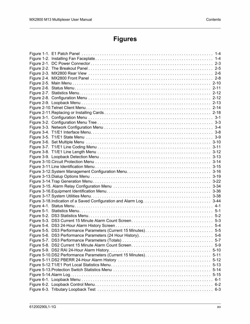
Figures
Figure 1-1. E1 Patch Panel . . . . . . . . . . . . . . . . . . . . . . . . . . . . . . . . . . . . . . . . . . . . . . . . . . . . . . . . . . 1-4Figure 1-2. Installing Fan Faceplate . . . . . . . . . . . . . . . . . . . . . . . . . . . . . . . . . . . . . . . . . . . . . . . . . . . . 1-4Figure 2-1. DC Power Connector . . . . . . . . . . . . . . . . . . . . . . . . . . . . . . . . . . . . . . . . . . . . . . . . . . . . . . 2-3Figure 2-2. The Breakout Panel . . . . . . . . . . . . . . . . . . . . . . . . . . . . . . . . . . . . . . . . . . . . . . . . . . . . . . . 2-5Figure 2-3. MX2800 Rear View . . . . . . . . . . . . . . . . . . . . . . . . . . . . . . . . . . . . . . . . . . . . . . . . . . . . . . . 2-6Figure 2-4. MX2800 Front Panel . . . . . . . . . . . . . . . . . . . . . . . . . . . . . . . . . . . . . . . . . . . . . . . . . . . . . . 2-8Figure 2-5. Main Menu . . . . . . . . . . . . . . . . . . . . . . . . . . . . . . . . . . . . . . . . . . . . . . . . . . . . . . . . . . . . . 2-10Figure 2-6. Status Menu . . . . . . . . . . . . . . . . . . . . . . . . . . . . . . . . . . . . . . . . . . . . . . . . . . . . . . . . . . . . 2-11Figure 2-7. Statistics Menu. . . . . . . . . . . . . . . . . . . . . . . . . . . . . . . . . . . . . . . . . . . . . . . . . . . . . . . . . . 2-12Figure 2-8. Configuration Menu . . . . . . . . . . . . . . . . . . . . . . . . . . . . . . . . . . . . . . . . . . . . . . . . . . . . . . 2-12Figure 2-9. Loopback Menu . . . . . . . . . . . . . . . . . . . . . . . . . . . . . . . . . . . . . . . . . . . . . . . . . . . . . . . . . 2-13Figure 2-10.Telnet Client Menu . . . . . . . . . . . . . . . . . . . . . . . . . . . . . . . . . . . . . . . . . . . . . . . . . . . . . . . 2-14Figure 2-11.Replacing or Installing Cards . . . . . . . . . . . . . . . . . . . . . . . . . . . . . . . . . . . . . . . . . . . . . . . 2-18Figure 3-1. Configuration Menu . . . . . . . . . . . . . . . . . . . . . . . . . . . . . . . . . . . . . . . . . . . . . . . . . . . . . . . 3-1Figure 3-2. Configuration Menu Tree . . . . . . . . . . . . . . . . . . . . . . . . . . . . . . . . . . . . . . . . . . . . . . . . . . . 3-3Figure 3-3. Network Configuration Menu . . . . . . . . . . . . . . . . . . . . . . . . . . . . . . . . . . . . . . . . . . . . . . . . 3-4Figure 3-4. T1/E1 Interface Menu. . . . . . . . . . . . . . . . . . . . . . . . . . . . . . . . . . . . . . . . . . . . . . . . . . . . . . 3-8Figure 3-5. T1/E1 State Menu . . . . . . . . . . . . . . . . . . . . . . . . . . . . . . . . . . . . . . . . . . . . . . . . . . . . . . . . 3-9Figure 3-6. Set Multiple Menu . . . . . . . . . . . . . . . . . . . . . . . . . . . . . . . . . . . . . . . . . . . . . . . . . . . . . . . 3-10Figure 3-7. T1/E1 Line Coding Menu . . . . . . . . . . . . . . . . . . . . . . . . . . . . . . . . . . . . . . . . . . . . . . . . . . 3-11Figure 3-8. T1/E1 Line Length Menu . . . . . . . . . . . . . . . . . . . . . . . . . . . . . . . . . . . . . . . . . . . . . . . . . . 3-12Figure 3-9. Loopback Detection Menu . . . . . . . . . . . . . . . . . . . . . . . . . . . . . . . . . . . . . . . . . . . . . . . . . 3-13Figure 3-10.Circuit Protection Menu . . . . . . . . . . . . . . . . . . . . . . . . . . . . . . . . . . . . . . . . . . . . . . . . . . . 3-14Figure 3-11.Line Identification Menu . . . . . . . . . . . . . . . . . . . . . . . . . . . . . . . . . . . . . . . . . . . . . . . . . . . 3-15Figure 3-12.System Management Configuration Menu. . . . . . . . . . . . . . . . . . . . . . . . . . . . . . . . . . . . . 3-16Figure 3-13.Dialup Options Menu . . . . . . . . . . . . . . . . . . . . . . . . . . . . . . . . . . . . . . . . . . . . . . . . . . . . . 3-19Figure 3-14.Trap Generation Menu . . . . . . . . . . . . . . . . . . . . . . . . . . . . . . . . . . . . . . . . . . . . . . . . . . . . 3-22Figure 3-15. Alarm Relay Configuration Menu . . . . . . . . . . . . . . . . . . . . . . . . . . . . . . . . . . . . . . . . . . . 3-34Figure 3-16.Equipment Identification Menu. . . . . . . . . . . . . . . . . . . . . . . . . . . . . . . . . . . . . . . . . . . . . . 3-36Figure 3-17.System Utilities Menu. . . . . . . . . . . . . . . . . . . . . . . . . . . . . . . . . . . . . . . . . . . . . . . . . . . . . 3-38Figure 3-18.Indication of a Saved Configuration and Alarm Log. . . . . . . . . . . . . . . . . . . . . . . . . . . . . . 3-44Figure 4-1. Status Menu . . . . . . . . . . . . . . . . . . . . . . . . . . . . . . . . . . . . . . . . . . . . . . . . . . . . . . . . . . . . . 4-1Figure 5-1. Statistics Menu. . . . . . . . . . . . . . . . . . . . . . . . . . . . . . . . . . . . . . . . . . . . . . . . . . . . . . . . . . . 5-1Figure 5-2. DS3 Statistics Menu. . . . . . . . . . . . . . . . . . . . . . . . . . . . . . . . . . . . . . . . . . . . . . . . . . . . . . . 5-2Figure 5-3. DS3 Current 15 Minute Alarm Count Screen . . . . . . . . . . . . . . . . . . . . . . . . . . . . . . . . . . . . 5-3Figure 5-4. DS3 24-Hour Alarm History Screen . . . . . . . . . . . . . . . . . . . . . . . . . . . . . . . . . . . . . . . . . . . 5-4Figure 5-5. DS3 Performance Parameters (Current 15 Minutes) . . . . . . . . . . . . . . . . . . . . . . . . . . . . . . 5-5Figure 5-6. DS3 Performance Parameters (24 Hour History). . . . . . . . . . . . . . . . . . . . . . . . . . . . . . . . . 5-6Figure 5-7. DS3 Performance Parameters (Totals) . . . . . . . . . . . . . . . . . . . . . . . . . . . . . . . . . . . . . . . . 5-7Figure 5-8. DS2 Current 15 Minute Alarm Count Screen . . . . . . . . . . . . . . . . . . . . . . . . . . . . . . . . . . . . 5-9Figure 5-9. DS2 RAI 24-Hour Alarm History. . . . . . . . . . . . . . . . . . . . . . . . . . . . . . . . . . . . . . . . . . . . . 5-10Figure 5-10.DS2 Performance Parameters (Current 15 Minutes) . . . . . . . . . . . . . . . . . . . . . . . . . . . . . 5-11Figure 5-11.DS2 PBERR 24-Hour Alarm History . . . . . . . . . . . . . . . . . . . . . . . . . . . . . . . . . . . . . . . . . 5-12Figure 5-12.T1/E1 Port Local Statistics Menu . . . . . . . . . . . . . . . . . . . . . . . . . . . . . . . . . . . . . . . . . . . . 5-13Figure 5-13.Protection Switch Statistics Menu . . . . . . . . . . . . . . . . . . . . . . . . . . . . . . . . . . . . . . . . . . . 5-14Figure 5-14.Alarm Log. . . . . . . . . . . . . . . . . . . . . . . . . . . . . . . . . . . . . . . . . . . . . . . . . . . . . . . . . . . . . . 5-15Figure 6-1. Loopback Menu . . . . . . . . . . . . . . . . . . . . . . . . . . . . . . . . . . . . . . . . . . . . . . . . . . . . . . . . . . 6-1Figure 6-2. Loopback Control Menu . . . . . . . . . . . . . . . . . . . . . . . . . . . . . . . . . . . . . . . . . . . . . . . . . . . . 6-2Figure 6-3. Tributary Loopback Test . . . . . . . . . . . . . . . . . . . . . . . . . . . . . . . . . . . . . . . . . . . . . . . . . . . 6-3
61200290L1-1G xv

Contents MX2800 M13 Multiplexer User Manual
Figure 6-4. Analog Network Loopback . . . . . . . . . . . . . . . . . . . . . . . . . . . . . . . . . . . . . . . . . . . . . . . . . . 6-3Figure 6-5. Digital Line/Network Loopback. . . . . . . . . . . . . . . . . . . . . . . . . . . . . . . . . . . . . . . . . . . . . . . 6-3Figure 6-6. Codec Loopback . . . . . . . . . . . . . . . . . . . . . . . . . . . . . . . . . . . . . . . . . . . . . . . . . . . . . . . . . 6-4Figure 6-7. Loopback Menu with BERT Selected. . . . . . . . . . . . . . . . . . . . . . . . . . . . . . . . . . . . . . . . . . 6-5Figure 6-8. DS3 Loopback Menu . . . . . . . . . . . . . . . . . . . . . . . . . . . . . . . . . . . . . . . . . . . . . . . . . . . . . . 6-6Figure 6-9. Line Loopback Test . . . . . . . . . . . . . . . . . . . . . . . . . . . . . . . . . . . . . . . . . . . . . . . . . . . . . . . 6-7Figure 6-10.Digital Loopback. . . . . . . . . . . . . . . . . . . . . . . . . . . . . . . . . . . . . . . . . . . . . . . . . . . . . . . . . . 6-7Figure 6-11.Metallic Loopback Test . . . . . . . . . . . . . . . . . . . . . . . . . . . . . . . . . . . . . . . . . . . . . . . . . . . . 6-8Figure 6-12.DS2 Loopback Menu . . . . . . . . . . . . . . . . . . . . . . . . . . . . . . . . . . . . . . . . . . . . . . . . . . . . . . 6-9Figure 6-13.DS2 Network Loopback Test . . . . . . . . . . . . . . . . . . . . . . . . . . . . . . . . . . . . . . . . . . . . . . . . 6-9Figure 7-1. Nonredundant Mode . . . . . . . . . . . . . . . . . . . . . . . . . . . . . . . . . . . . . . . . . . . . . . . . . . . . . . 7-1Figure 7-2. Circuit Failure Recovery Mode. . . . . . . . . . . . . . . . . . . . . . . . . . . . . . . . . . . . . . . . . . . . . . . 7-2Figure 7-3. Circuit and Network Failure Recovery Mode . . . . . . . . . . . . . . . . . . . . . . . . . . . . . . . . . . . . 7-3Figure 8-1. Nonredundant Power Mode . . . . . . . . . . . . . . . . . . . . . . . . . . . . . . . . . . . . . . . . . . . . . . . . . 8-1Figure 8-2. Power Supply Failure Recovery Mode. . . . . . . . . . . . . . . . . . . . . . . . . . . . . . . . . . . . . . . . . 8-2Figure 8-3. Power Supply and Source Failure Recovery Mode . . . . . . . . . . . . . . . . . . . . . . . . . . . . . . . 8-3Figure 8-4. Battery Backup System . . . . . . . . . . . . . . . . . . . . . . . . . . . . . . . . . . . . . . . . . . . . . . . . . . . . 8-4
xvi 61200290L1-1G

MX2800 M13 Multiplexer User Manual Contents
Tables
Table 2-1. DC Connector Symbol Definitions . . . . . . . . . . . . . . . . . . . . . . . . . . . . . . . . . . . . . . . . . . . . 2-3Table 2-2. MX2800 Review View Identifiers . . . . . . . . . . . . . . . . . . . . . . . . . . . . . . . . . . . . . . . . . . . . . 2-6Table 2-3. LED Conditions for Active Cards . . . . . . . . . . . . . . . . . . . . . . . . . . . . . . . . . . . . . . . . . . . . 2-16Table 2-4. LED Conditions for Standby Cards . . . . . . . . . . . . . . . . . . . . . . . . . . . . . . . . . . . . . . . . . . 2-17Table 2-5. T1/E1 LED Conditions . . . . . . . . . . . . . . . . . . . . . . . . . . . . . . . . . . . . . . . . . . . . . . . . . . . . 2-17Table 3-1. XCV Threshold Limits . . . . . . . . . . . . . . . . . . . . . . . . . . . . . . . . . . . . . . . . . . . . . . . . . . . . . 3-6Table 3-2. XCV Threshold Limits for T1/E1. . . . . . . . . . . . . . . . . . . . . . . . . . . . . . . . . . . . . . . . . . . . . 3-15Table 3-3. Trap Descriptions . . . . . . . . . . . . . . . . . . . . . . . . . . . . . . . . . . . . . . . . . . . . . . . . . . . . . . . 3-22Table 3-4. Console Menu User Privileges. . . . . . . . . . . . . . . . . . . . . . . . . . . . . . . . . . . . . . . . . . . . . . 3-30Table 3-5. Types of Alarms in Alarm Relay Configuration . . . . . . . . . . . . . . . . . . . . . . . . . . . . . . . . . 3-34Table 3-6. Syslog Severity Levels . . . . . . . . . . . . . . . . . . . . . . . . . . . . . . . . . . . . . . . . . . . . . . . . . . . . 3-37Table 3-7. Self-Test Results . . . . . . . . . . . . . . . . . . . . . . . . . . . . . . . . . . . . . . . . . . . . . . . . . . . . . . . . 3-39Table 4-1. Network State Conditions. . . . . . . . . . . . . . . . . . . . . . . . . . . . . . . . . . . . . . . . . . . . . . . . . . . 4-2Table 4-2. Alarm Conditions. . . . . . . . . . . . . . . . . . . . . . . . . . . . . . . . . . . . . . . . . . . . . . . . . . . . . . . . . 4-2Table 4-3. Remote Alarm Conditions . . . . . . . . . . . . . . . . . . . . . . . . . . . . . . . . . . . . . . . . . . . . . . . . . . 4-3Table 4-4. Power Supply Conditions . . . . . . . . . . . . . . . . . . . . . . . . . . . . . . . . . . . . . . . . . . . . . . . . . . . 4-4Table 4-5. System State Alarm Types . . . . . . . . . . . . . . . . . . . . . . . . . . . . . . . . . . . . . . . . . . . . . . . . . 4-4Table 4-6. Controller Card States . . . . . . . . . . . . . . . . . . . . . . . . . . . . . . . . . . . . . . . . . . . . . . . . . . . . . 4-5Table 4-7. Protection Types . . . . . . . . . . . . . . . . . . . . . . . . . . . . . . . . . . . . . . . . . . . . . . . . . . . . . . . . . 4-5Table 4-8. DS2 States . . . . . . . . . . . . . . . . . . . . . . . . . . . . . . . . . . . . . . . . . . . . . . . . . . . . . . . . . . . . . . 4-6Table 4-9. T1/E1 States . . . . . . . . . . . . . . . . . . . . . . . . . . . . . . . . . . . . . . . . . . . . . . . . . . . . . . . . . . . . 4-6Table 5-1. Alarm Counts . . . . . . . . . . . . . . . . . . . . . . . . . . . . . . . . . . . . . . . . . . . . . . . . . . . . . . . . . . . . 5-2Table 7-1. Configuration Requirements for Circuit Recovery . . . . . . . . . . . . . . . . . . . . . . . . . . . . . . . . 7-2Table 9-1. TL1 Account Privileges . . . . . . . . . . . . . . . . . . . . . . . . . . . . . . . . . . . . . . . . . . . . . . . . . . . . 9-2Table 9-2. TL1 Commands . . . . . . . . . . . . . . . . . . . . . . . . . . . . . . . . . . . . . . . . . . . . . . . . . . . . . . . . . . 9-6Table 9-3. MX2800 Alarm Events . . . . . . . . . . . . . . . . . . . . . . . . . . . . . . . . . . . . . . . . . . . . . . . . . . . . 9-12Table 9-4. MX2800 Informational Events . . . . . . . . . . . . . . . . . . . . . . . . . . . . . . . . . . . . . . . . . . . . . . 9-16Table 9-5. TL1 Error Codes. . . . . . . . . . . . . . . . . . . . . . . . . . . . . . . . . . . . . . . . . . . . . . . . . . . . . . . . . 9-17Table 9-6. TL1 Editing Data Dictionary for DS3 . . . . . . . . . . . . . . . . . . . . . . . . . . . . . . . . . . . . . . . . . 9-20Table 9-7. TL1 Editing Data Dictionary for DS2 . . . . . . . . . . . . . . . . . . . . . . . . . . . . . . . . . . . . . . . . . 9-23Table 9-8. TL1 Editing Data Dictionary for DS1 . . . . . . . . . . . . . . . . . . . . . . . . . . . . . . . . . . . . . . . . . 9-24Table 9-9. TL1 Editing Data Dictionary for EQPT . . . . . . . . . . . . . . . . . . . . . . . . . . . . . . . . . . . . . . . . 9-27Table 9-10. DS3 TL1 Loopback Commands . . . . . . . . . . . . . . . . . . . . . . . . . . . . . . . . . . . . . . . . . . . . . 9-30Table 9-11. DS2 TL1 Loopback Commands . . . . . . . . . . . . . . . . . . . . . . . . . . . . . . . . . . . . . . . . . . . . . 9-30Table 9-12. DS1 TL1 Loopback Commands . . . . . . . . . . . . . . . . . . . . . . . . . . . . . . . . . . . . . . . . . . . . . 9-31Table A-1. MX2800 ATP Checklist . . . . . . . . . . . . . . . . . . . . . . . . . . . . . . . . . . . . . . . . . . . . . . . . . . . A-12Table B-1. Craft Port Pin Assignments . . . . . . . . . . . . . . . . . . . . . . . . . . . . . . . . . . . . . . . . . . . . . . . . . B-1Table B-2. LAN Port Pin Assignments. . . . . . . . . . . . . . . . . . . . . . . . . . . . . . . . . . . . . . . . . . . . . . . . . . B-1Table B-3. Modem Port Pin Assignment . . . . . . . . . . . . . . . . . . . . . . . . . . . . . . . . . . . . . . . . . . . . . . . . B-2Table B-4. Amphenol Pin Assignments . . . . . . . . . . . . . . . . . . . . . . . . . . . . . . . . . . . . . . . . . . . . . . . . . B-2
61200290L1-1G xvii

Contents MX2800 M13 Multiplexer User Manual
This page is intentionally blank.
xviii 61200290L1-1G

SECTION 1, PRODUCT OVERVIEW
Section 1Product Overview
1. INTRODUCTIONThe MX2800 is an M13 multiplexer that consolidates T1 and E1 signals into a T3 circuit. This unit provides a cost-effective, versatile tool for combining independent T1s, E1s, or a combination of the two over the same T3 circuit.
The MX2800 houses two hot-swappable controller cards which provide 1:1 redundancy for the T1 and T3 signals, as well as the T3 connections.
Embedded simple network management protocol (SNMP) and Telnet are available through the modem port using serial line internet protocol/point-to-point protocol (SLIP/PPP) or through the 10Base-T Ethernet port. Using the Management Information Base II (MIB II), RFC 1407 standards, and an ADTRAN enterprise MIB, the MX2800 can be configured, monitored, and diagnosed with standard SNMP network management programs such as Hewlett Packard’s HP OpenView™ and Cabletron’s Spectrum®. In addition, the SysLog Host Daemon allows remote monitoring, collecting, and logging of MX2800 events in realtime. This information is useful during installation setups and/or troubleshooting.
Complete configuration, loopbacks, and performance monitoring are available through SNMP, Telnet, or a VT100 terminal interface. This connection can be made via Ethernet, a local EIA-232 link, or through the built-in V.34 modem. The modem can dial out a “cry for help” for units located in unmanned facilities. The MX2800 is designed for installation in a 19-inch or 23-inch rack.
The major features of the MX2800 are as follows:
• Built-in 1:1 redundancy
• Hot-swappable controller cards
• Independent, dual-load sharing, redundant power supplies
• Embedded SNMP and Telnet management through 10Base-T Ethernet or SLIP/PPP dialup
• Detailed performance monitoring for local and remote units
• Simplified configuration through the VT100 terminal menu structure
• Integrated V.34 modem for dial-up and dial-down access
• Capability of backhauling multiple service types (T1/E1)
• AC or DC power
• Available –48V or 24V power supplies
• External DS3 clock option
• M13 and C-bit signaling support
61200290L1-1G 1-1

Section 1, Product Overview MX2800 M13 Multiplexer User Manual
• NEBS Level 3 compliant
NOTEInformation regarding the built-in modem applies to the part numbers4202290L1, 4202290L2, 4202290L3, and 4202290L4.
2. CONTROLLER CARD 1:1 REDUNDANCYThe MX2800 supports two hot-swappable controller cards which provide 1:1 redundancy for the T1 and T3 signals and connections. With two cards installed, the MX2800 can recover from circuit or network failure. Refer to Section 7, Circuit and Network Redundancy for more information.
3. T3 OVERVIEWA T3 provides the same bandwidth as 28 T1s. Typically, leasing a T3 line costs the same as eight to ten T1s. Using the MX2800, a single T3 can provide internet connectivity and voice (local and long distance) to individual sites across up to 28 individual DSX-1s. T3 is also extremely cost effective for backhauling local and long distance voice.
4. SNMPThe MX2800’s embedded SNMP feature allows the unit to be accessed and controlled by a network manager through the 10Base-T local area network (LAN) port. The MX2800 supports the MIB-II standard, RFC 1213, and the ADTRAN Enterprise Specific MIB.
NOTEMIB files are available from ADTRAN in the support section of theADTRAN Web page at www.adtran.com.
The term SNMP broadly refers to the message protocols used to exchange information between the network management system (NMS) and the managed devices, as well as to the structure of device management databases. SNMP has three basic components: the network manager, the agent, and the MIB.
Network Manager The network manager is a set of control programs that collect, control, and present data pertinent to the operation of the network devices. These programs reside on a network management station.
1-2 61200290L1-1G

MX2800 M13 Multiplexer User Manual Product Overview, Section 1
AgentThe agent is a control program that resides in every network device. This program responds to queries and commands from the network manager, returns requested information or invokes configuration changes initiated by the manager, and sends unsolicited traps to the manager.
MIBAn MIB is an industry standard presentation of all status and configuration parameters supported by a network device.
5. TELNETTelnet provides a password protected, remote login facility to the MX2800 that allows a remote user to control the MX2800 through the terminal menus. Only one Telnet menu session may be active at a time.
6. TL1Transaction Language 1 (TL1) is an ASCII-based language that supports both command-response and autonomous (NE) message generation. Commonly, TL1 is used over an X.25 packet network but is completely independent of any physical layer protocols. For the MX2800, TL1 is implemented as a Telnet session running over Ethernet or PPP. Currently, up to eight TL1 Telnet connections can be active at a time.
7. AVAILABLE OPTIONSThe following optional equipment is available for use with the MX2800. Contact a local distributor or the ADTRAN Sales Department for more information. Refer to Appendix F, Warranty for contact information.
Breakout Panel (P/N 1200291L1)The optional breakout panel connects to the MX2800 and provides 28 RJ connectors for the individual T1s/E1s. Shipment includes two six-foot, 64-pin to 64-pin amphenol cables which allow direct cabling to the MX2800. Refer to Connecting the Breakout Panel on page 2-5 for more information.
E1 Patch Panel (P/N 1200291L5)The optional E1 patch panel connects to the MX2800 and provides 28 pairs of BNC connectors for E1 deployment (21 of which are used for E1 deployment). See Figure 1-1 on page 1-4.
61200290L1-1G 1-3

Section 1, Product Overview MX2800 M13 Multiplexer User Manual
Figure 1-1. E1 Patch Panel
Shipment includes two six-foot, 64-pin to 64-pin amphenol cables for direct cabling to the MX2800. Refer to Connecting the E1 Patch Panel on page 2-5 or more information.
Battery Backup (P/N 4175043L2)The battery backup system provides power backup in the event of power loss. This system includes the battery, an AC battery charger, and an alarm cable.
Fan Faceplate (P/N 1200466L1)The MX2800 fan faceplate provides the means for additional heat dissipation, allowing multiple units to be stacked directly over each other. The fan faceplate replaces the original faceplate. It is used with the 1202289L1, 1202289L2, and 1202289L3 power supplies. Figure 1-2 shows how the fan faceplate is installed on the chassis.
Figure 1-2. Installing Fan Faceplate
TX RXOPEN
CH 26EARTH
OPEN
EARTH
OPEN
CH 28EARTH
CH 3
TX RXOPEN
CH 1EARTH
OPEN
CH 2EARTH
OPEN
EARTH
OPEN
CH 4EARTH
OPEN
CH 5EARTH
CH 8
TX RXOPEN
CH 6EARTH
OPEN
CH 7EARTH
OPEN
EARTH
OPEN
CH 9EARTH
OPEN
CH 10EARTH
CH 13
TX RXOPEN
CH 11EARTH
OPEN
CH 12EARTH
OPEN
EARTH
OPEN
CH 14EARTH
OPEN
CH 15EARTH
CH 18
TX RXOPEN
CH 16EARTH
OPEN
CH 17EARTH
OPEN
EARTH
OPEN
CH 19EARTH
OPEN
CH 20EARTH
CH 23
TX RXOPEN
CH 21EARTH
OPEN
CH 22EARTH
OPEN
EARTH
OPEN
CH 24EARTH
OPEN
CH 25EARTH
CH 27
ONONON
ONON
ONON
ONON
ONON
ONONON
ONON
ONON
ONON
ONON
ONONON
ONON
ONON
ONON
ONON
ONONON
ONON
ONON
ONON
ONON
ONONON
ONON
ONON
ONON
ONON
ONON
ONON
ONON
1-4 61200290L1-1G

SECTION 2, INSTALLATION AND OPERATION
Section 2Installation and Operation
1. INTRODUCTIONThe first three tasks for installing and operating the MX2800 are to unpack, inspect, and power up. The next three subsections detail the tasks. Additional subsections provide information for mounting the MX2800 into an equipment rack, making the proper connection to the back panel, identifying the front panel indicators and modular jack, and outlining the addition or removal of a card.
2. RECEIVING INSPECTIONCarefully inspect the MX2800 for any damage that might have occurred in shipment. If damage is suspected, file a claim immediately with the carrier, keep the original packaging for damage verification and/or returning the unit, and contact ADTRAN Customer Service. For warranty information, refer to Appendix F, Warranty.
3. ADTRAN SHIPPING CONTENTSAfter unpacking the MX2800 unit but before an initial power up, be sure that the following items are present:
• MX2800 unit
• DC or AC power supply (Two power supplies come with the Redundant versions.)
• Controller card (Two cards come with the Redundant versions.)
• 8-pin to 6-pin modular cable (modem version only)
• 8-pin to 8-pin modular cable
• 8-pin modular to DB-9 female connector
• Two 4-position terminal lug connectors
• 3-position terminal lug connector
• Six-foot AC power cable (AC version only)
• Mounting ears and screws for 19-inch or 23-inch rack installation
• User manual or CD containing the User Manual
61200290L1-1G 2-1

Section 2, Installation and Operation MX2800 M13 Multiplexer User Manual
NOTEMIB files are available from ADTRAN in the support section of theADTRAN Web page at www.adtran.com.
4. POWER UPThe AC version of the MX2800 is provided with a 6-foot power cable terminated in a three-prong plug which is connected to a grounded 120 VAC power receptacle.
NOTEPower to the AC version of the MX2800 must be provided from agrounded 120 VAC power receptacle.
The DC version of the MX2800 is provided with two 4-position modular terminal lug connectors. These connectors simplify the initial wiring and connection or disconnection of the DC power when replacing rackmount units.
NOTEA 3-amp fuse is recommended for use in the fuse and alarm panel thatfeeds the MX2800.
For more detailed information on power connections, refer to Section 8, Power Loss Recovery.
Once the modular connector is wired, push it firmly into one of the rear panel power connectors. Figure 2-1 on page 2-3 and Table 2-1 on page 2-3 illustrate the DC power connector and give definitions for the four connector symbols.
NOTEThe chassis should be connected to an earth ground using the ground studlocated between the AC and DC power sources on the rear panel.
2-2 61200290L1-1G

MX2800 M13 Multiplexer User Manual Installation and Operation, Section 2
Figure 2-1. DC Power Connector
The following UL requirements must be met during installation of the MX2800 DC version:
1. Disconnect all power sources prior to servicing. Unit may use multiple power sources.
2. Input: Minimum 48 VDC, 0.8 amps
3. Input: Minimum 120 VAC, 0.32 amps
4. Connect to a reliably grounded –48 VDC source which is electrically isolated from the AC source. Use 24 VDC source for 1202289L3.
5. The branch circuit overcurrent protection must be a fuse or circuit breaker rated minimum 48 VDC, maximum 20 amps.
Table 2-1. DC Connector Symbol Definitions
Symbol Definition
PWR FAIL Battery backup connector. If the AC fails, a trap is sent to alert user when connected to the 4175043L2 battery backup or equivalent system.
– Negative side of DC power source (usually –48 VDC)
RET Positive side of DC power source (usually ground)
Frame Ground
DC POWER 115 AC 50/60Hz0.8A
PWRFAIL +
T R S T RCLKA
CLKB
S
–
LAN
NONCRITICAL
DSX-1/E1(OUT)
DSX-1/E1(IN)
NO COM NC
CRITICAL
MODEM
OUT IN
A
B
AB
DS3/STS-1
PWRFAIL +–
PWRFAIL
+
US
E C
OP
PE
RC
ON
DU
CTO
RS
ON
LY!
-48V 0.7A+24V 1.5A
-48V 0.7A
+24V 1.5A
61200290L1-1G 2-3

Section 2, Installation and Operation MX2800 M13 Multiplexer User Manual
6. A readily accessible disconnect device that is suitably approved and rated must be incorporated in the field wiring.
7. The chassis should be connected to an earth ground using the ground stud located between the AC and DC power sources on the rear panel.
8. The unit must be installed in accordance with the requirements of NEC NFPA 70.
9. The unit must be installed in accordance with Articles 400 and 364.8 of the National Electrical Code NFPA 70 when installed outside of a Restricted Access Location (i.e., Central Office, behind a locked door, service personnel area only).
10. Care should be taken not to upset the stability of the equipment rack after installation is complete.
CAUTIONUse copper conductors only for DC power and ground connection.
5. RACKMOUNT INSTALLATIONThe MX2800 can be mounted into a standard 19-inch or 23-inch equipment rack. Follow these steps to mount the unit into a rack:
1. Install the mounting flanges on each side of the MX2800 at one of the three available positions.
CAUTIONBe sure to install the flanges with the screws provided.
2. After the flanges have been installed, position the MX2800 at the correct location within the rack and secure the mounting flanges to the mounting rails of the rack.
3. Make all network, DTE, and power connections to the rear of the unit. Refer to Power Up on page 2-2 for more information on making the DC power connection.
4. Using the 8-position modular to DB-9 female connector and the 8-pin to 8-pin modular cable, connect a VT100 terminal device to the CRAFT port on the front panel of the unit.
NOTETwo MX2800s can be stacked with out any spacing between the units.ADTRAN recommends 1U (1.75”) of separation above and below thetwo stacked units. This spacing allows the units to dissipate heat. Thedesign of the MX2800 uses the chassis to distribute heat generated by theunit’s internal cards. This design allows the units to operate without acooling fan, thus increasing overall reliability of the units.
2-4 61200290L1-1G

MX2800 M13 Multiplexer User Manual Installation and Operation, Section 2
Connecting the Breakout PanelThe optional breakout panel (P/N 1200291L1) connects to the MX2800 via the IN and OUT amphenol connectors located on the back of the unit and provides 28 RJ connectors for the individual T1s/E1s. Shipment includes two six-foot, 64-pin to 64-pin amphenol cables for direct cabling to the MX2800. Connect the breakout panel’s IN amphenol connector to the MX2800’s IN amphenol connector and the breakout panel’s OUT amphenol connector to the MX2800’s OUT amphenol connector. See Figure 2-2.
Figure 2-2. The Breakout Panel
Connecting the E1 Patch PanelThe optional E1 patch panel (P/N 1200291L5) connects to the MX2800 via the TX and RX amphenol connectors located on the back of the unit and provides 28 pairs of BNC connectors for the individual T1/E1s. Shipment includes two 6-foot, 64-pin to 64-pin amphenol cables for direct cabling to the MX2800. Connect the E1 patch panel’s TX amphenol connector to the MX2800’s IN amphenol connector and the E1 patch panel’s RX amphenol connector to the MX2800's OUT amphenol connector.
�
�
�
�
�
�
�
�
�
�
�
1 3 5 7 9 11 13 15 17 19 21 23 25 27
2 4 6 8 10 12 14 16 18 20 22 24 26 28
INOUT
Cable 2
Cable 1
���
DC POWER 115 AC 50/60Hz0.8A
PWRFAIL +
T R S T RCLKA
CLKB
S
–
LAN
NONCRITICAL
DSX-1/E1(OUT)
DSX-1/E1(IN)
NO COM NC
CRITICAL
MODEM
OUT IN
A
B
AB
DS3/STS-1
PWRFAIL +– U
SE
CO
PP
ER
CO
ND
UC
TOR
S O
NLY
!
-48V 0.7A+24V 1.5A
FRONT VIEW
REAR VIEW
61200290L1-1G 2-5
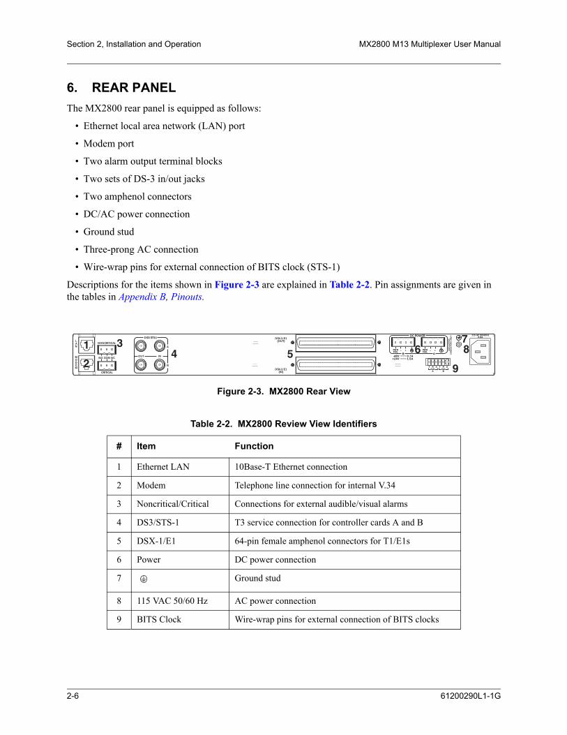
Section 2, Installation and Operation MX2800 M13 Multiplexer User Manual
6. REAR PANELThe MX2800 rear panel is equipped as follows:
• Ethernet local area network (LAN) port
• Modem port
• Two alarm output terminal blocks
• Two sets of DS-3 in/out jacks
• Two amphenol connectors
• DC/AC power connection
• Ground stud
• Three-prong AC connection
• Wire-wrap pins for external connection of BITS clock (STS-1)
Descriptions for the items shown in Figure 2-3 are explained in Table 2-2. Pin assignments are given in the tables in Appendix B, Pinouts.
Figure 2-3. MX2800 Rear View
Table 2-2. MX2800 Review View Identifiers
# Item Function
1 Ethernet LAN 10Base-T Ethernet connection
2 Modem Telephone line connection for internal V.34
3 Noncritical/Critical Connections for external audible/visual alarms
4 DS3/STS-1 T3 service connection for controller cards A and B
5 DSX-1/E1 64-pin female amphenol connectors for T1/E1s
6 Power DC power connection
7 Ground stud
8 115 VAC 50/60 Hz AC power connection
9 BITS Clock Wire-wrap pins for external connection of BITS clocks
DC POWER 115 AC 50/60Hz0.8A
PWRFAIL
+
T R S T RCLKA
CLKB
S
–
LAN
NONCRITICAL
DSX-1/E1(OUT)
DSX-1/E1(IN)
NO COM NC
CRITICAL
MODEM
OUT IN
A
B
A-48V 0.7A
B
DS3/STS-1
PWRFAIL
+–
+24V 1.5A
1
2
34 5 6
78
9
US
E C
OP
PE
RC
ON
DU
CTO
RS
ON
LY!
2-6 61200290L1-1G

MX2800 M13 Multiplexer User Manual Installation and Operation, Section 2
LAN PortThe LAN port is an 8-pin modular connector that provides a 10Base-T Ethernet LAN interface. This LAN interface is used for SNMP and Telnet control.
NOTEConnect the LAN port to intra-building wiring only.
Modem PortThe modem port is an 8-pin modular jack that provides a telephone line (POTS) connection for the internal V.34 modem.
NOTEInformation regarding the built-in modem applies to the part numbers4202290L1, 4202290L2, 4202290L3, and 4202290L4.
The MX2800 can be configured as a dial-in host and also as a dial-out-on-trap device (the unit dials out to a specified host to report error conditions).
Noncritical and Critical Alarm ConnectorsThe alarm connectors connect to the three contacts of a Form C type relay on the main board of the MX2800. This relay is activated any time the MX2800 detects an alarm condition on the T3 network interface. Both NC (normally closed) and NO (normally open) contacts are provided.
Connect alarms to one of the three-position modular terminal lug connectors. These connectors simplify the initial wiring and connection or disconnection of the alarms when replacing rackmount units. Once a modular connector is wired, push it firmly into the rear panel NONCRITICAL or CRITICAL connector.
The alarm functions can be enabled or disabled through the Alarm Relays section of the Configuration menu. For more information, refer to Alarm Relay Configuration on page 3-33.
DSX-3 InterfacesThe DSX-3 network interfaces are full-duplex circuits provided by four BNC coaxial cable connections (two for each controller card). The receive data from the network is connected to the Rx (IN) connectors, while the transmit data from the MX2800 is connected to the Tx (OUT) connectors. Refer to Section 7, Circuit and Network Redundancy for more specific information about connecting the DS3 interface in redundant and nonredundant systems.
61200290L1-1G 2-7

Section 2, Installation and Operation MX2800 M13 Multiplexer User Manual
NOTEDSX-3 interfaces must be connected using coaxial cables that have theshields grounded at both ends.
DSX-1/E1 InterfacesThe DSX-1/E1 interfaces are 64-pin amphenol connectors. These interfaces provide Tx and Rx connections between the unit and equipment such as wire-wrap patch panels, punch-down panels, or breakout panels.
NOTEConnect the DSX-1/E1 interfaces to intra-building wiring only.
Power ConnectionThe DC power connections are described in Power Up on page 2-2.
7. FRONT PANELThe MX2800 front panel is shown in Figure 2-4. Descriptions of each part of the front panel follow:
• Craft Port on page 2-8
• ACO Buttons on page 2-15
• Power Supply A/B Status LEDs on page 2-15
• Controller Cards Status LEDs on page 2-15
• T1/E1 Status LEDs on page 2-17
Figure 2-4. MX2800 Front Panel
Craft PortThe craft port, an 8-pin modular jack, provides connection to a VT100 EIA-232 compatible interface (using the supplied 8-pin modular to DB-9 female connector and the 8-pin to 8-pin modular cable).
ACT
NET
ALM
PRF
2-8 61200290L1-1G

MX2800 M13 Multiplexer User Manual Installation and Operation, Section 2
Establishing Terminal Connection
NOTEA Telnet menu session has priority over a terminal menu session throughthe craft port. If a terminal menu session is active when a Telnet menusession is initiated, the terminal menu session will be disabled while theTelnet menu session is active.
To connect the MX2800 to a VT100 terminal, follow this procedure:
1. Configure the VT100 terminal for 9600, 19200, 38400, or 57600 baud, 8-bit characters, no parity, and one stop bit (xxxx, 8N1).
2. Using the ADTRAN-provided terminal interface cable adapter, connect the DTE port of a terminal to the 8-pin modular jack labeled CRAFT on the MX2800 front panel.
3. Initialize the terminal session.
4. Press ENTER repeatedly until the username prompt appears.
5. Enter the username. The factory default username is adtran. The password prompt appears.
6. Enter the password. The factory default password is adtran. The Main Menu appears. See Figure 2-5 on page 2-10.
Main MenuMake selections on the Main Menu by entering the number corresponding to the chosen parameter or the desired key strokes. Refer to Navigating Within the Menus on page 2-10
NOTEA new Telnet session may take priority over an existing one if a usernameand password are provided that have ADMIN privileges
61200290L1-1G 2-9
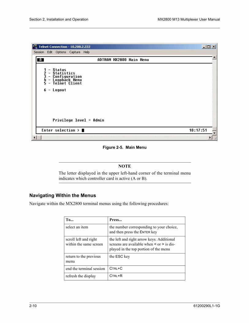
Section 2, Installation and Operation MX2800 M13 Multiplexer User Manual
Figure 2-5. Main Menu
NOTEThe letter displayed in the upper left-hand corner of the terminal menuindicates which controller card is active (A or B).
Navigating Within the MenusNavigate within the MX2800 terminal menus using the following procedures:
To... Press...
select an item the number corresponding to your choice, and then press the ENTER key
scroll left and right within the same screen
the left and right arrow keys. Additional screens are available when < or > is dis-played in the top portion of the menu
return to the previous menu
the ESC key
end the terminal session CTRL+C
refresh the display CTRL+R
2-10 61200290L1-1G

MX2800 M13 Multiplexer User Manual Installation and Operation, Section 2
The MX2800 Main Menu consists of the following sections:
StatusProvides information on the current state of the DS3, power supplies, system, DS2s, and T1/E1 lines. See Figure 2-6 for an illustration. Refer to Section 4, Status for more detailed information.
Figure 2-6. Status Menu
StatisticsProvides detailed statistical information (both current and historical) for the DS3, DS2s, and T1/E1 lines. See Figure 2-7 on page 2-12 for the Statistics menu. Refer to Statistics on page 5-1 for more detailed information.
scroll up and down within the same screen
the up and down arrow keys. Additional screens are available when ∧ or ∨ is dis-played in the top portion of the menu.
To... Press...
61200290L1-1G 2-11

Section 2, Installation and Operation MX2800 M13 Multiplexer User Manual
Figure 2-7. Statistics Menu
ConfigurationSets DS3 network, T1/E1, and system management parameters. See Figure 2-8. Refer to Section 3, Configuration for more detailed information.
Figure 2-8. Configuration Menu
2-12 61200290L1-1G
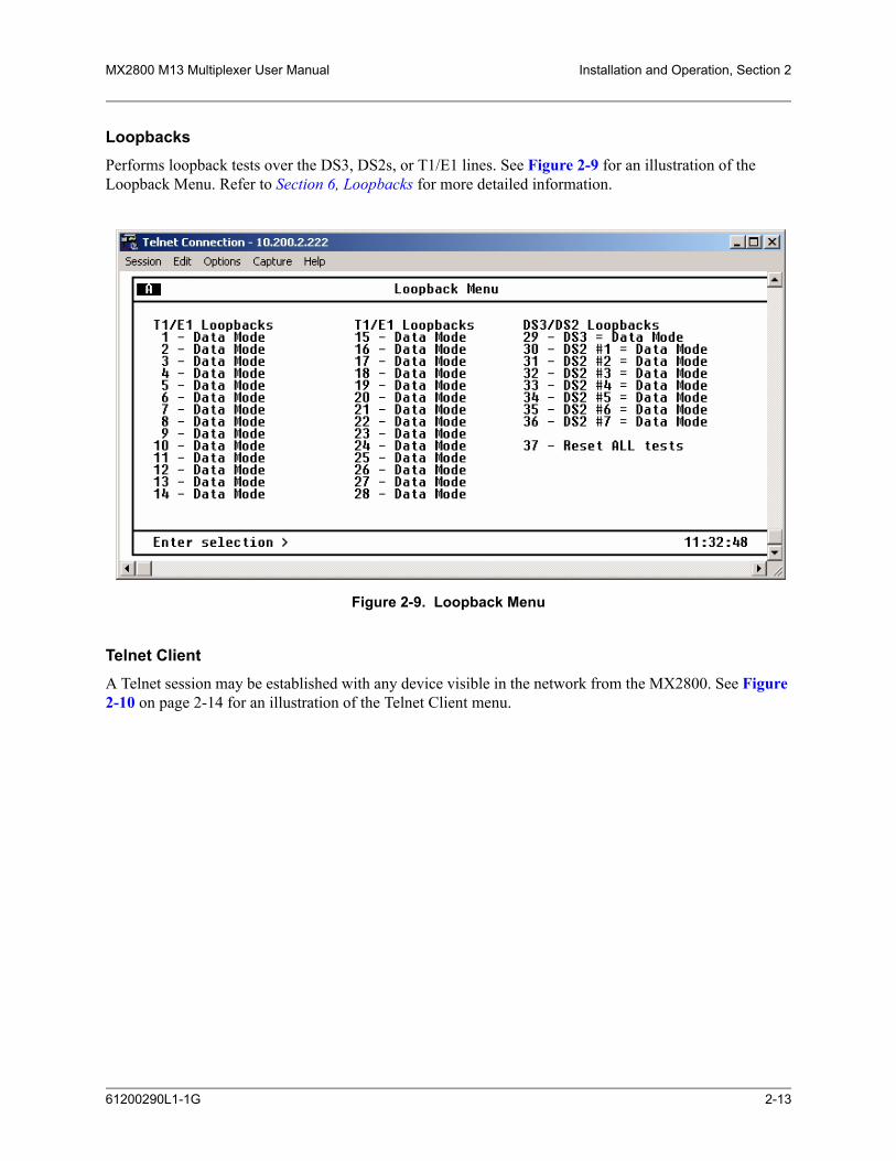
MX2800 M13 Multiplexer User Manual Installation and Operation, Section 2
LoopbacksPerforms loopback tests over the DS3, DS2s, or T1/E1 lines. See Figure 2-9 for an illustration of the Loopback Menu. Refer to Section 6, Loopbacks for more detailed information.
Figure 2-9. Loopback Menu
Telnet ClientA Telnet session may be established with any device visible in the network from the MX2800. See Figure 2-10 on page 2-14 for an illustration of the Telnet Client menu.
61200290L1-1G 2-13

Section 2, Installation and Operation MX2800 M13 Multiplexer User Manual
Figure 2-10. Telnet Client Menu
From the Telnet Client menu, specify the destination IP address and the desired TCP port number. Attempt to establish the TCP connection.
Once the connection is established, the new session becomes visible in the menu and all user inputs are forwarded to the destination address. When the session with the destination device is terminated, the MX2800 menu returns to the Telnet Client menu and all user input are processed locally by the MX2800.
NOTEAn attempted or established connection can be terminated by using theescape sequence. This escape sequence is displayed for reference at thebottom of the Telnet Client menu and consists of the control key plus theright bracket key (CTRL+]).
A connection can be established with the Telnet Client regardless of how the MX2800 (via craft, LAN port, modem port, or IP forwarding over the DS3 PMDL link) is accessed. The MX2800 supports only one menu session at a time.
CAUTIONThe MX2800 does not reliably support binary file transfers (XModem,YModem, etc.) over the built-in Telnet Client because of compatibilityissues involving the handling of certain control characters by someterminal applications and binary file transfer protocols.
2-14 61200290L1-1G

MX2800 M13 Multiplexer User Manual Installation and Operation, Section 2
LogoutThe Logout selection ends the terminal session and logs out of the system. A valid username and password are required before a new session can begin. The unit will also log out of a terminal session automatically if the session remains inactive for a certain period of time. For more information, see the section Terminal Time Out on page 3-33.
Privilege LevelThe privilege level of the currently active terminal session is displayed in this field.
ACO ButtonsThe ACO (alarm cut off) buttons turn off an active audible alarm. Since the buttons are recessed, use a pen or other pointed instrument to press them. Once an ACO button deactivates an alarm, the alarm remains disabled until the condition has cleared.
Alarms can also be turned off remotely by using a selection found in the Status menu. For more information, refer to Acknowledge Alarms (ACO) on page 4-6.
LED DescriptionsThe MX2800 has LED status indicators for the power supplies, the DS3 state, the controller cards, and the individual T1s/E1s. These LEDs are identified below:
Power Supply A/B Status LEDsThe PWR LED is active when the unit is on and receiving full power. The CHK LED is active when the power supply is failing or is providing low power and needs to be checked.
Controller Cards Status LEDsThe STATUS LEDs apply to the two controller cards. The LEDs provided are ACT (active), DS3, ALM (alarm), and PRF (performance). Various conditions are indicated by the state of the LED (its color and whether it blinks, alternates color, or is on solid). The condition descriptions vary depending on whether the LED represents the active controller card or the controller card on standby. The following tables provide LED definitions for the active cards (see Table 2-3 on page 2-16) and T1/E1 cards (see Table 2-4 on page 2-17).
61200290L1-1G 2-15

Section 2, Installation and Operation MX2800 M13 Multiplexer User Manual
NOTEThe PRF (performance) LED refers to the DS3 only
Table 2-3. LED Conditions for Active Cards
LED LED State Card Condition
ACT Green solid Normal (all OK)
Green/amber alternating Normal + console open
Red solid Self test failed
Amber solid Software update in progress
Red/amber alternating Self test failed + console open
Red blinking Card failure
NET Green solid Normal (all OK)
Red blinking LOS
Red solid AIS, LOF, RAI, idle alarms
Amber solid In test (Local)
Amber flashing In test (Remote)
Red/amber alternating In test with alarms
ALM Green solid Normal (no alarm)
Red blinking Critical alarm
Red solid Non-critical alarm
Amber blinking Critical alarm suppressed (ACO button was pushed)
Amber solid Non-critical alarm suppressed (ACO button was pushed)
PRF Green solid Normal (all OK)
Red flash (once per event) Single/burst CV
Red blinking Continuous code violations
Red solid XCV threshold exceeded (refer to XCV Threshold on page 3-15)
2-16 61200290L1-1G
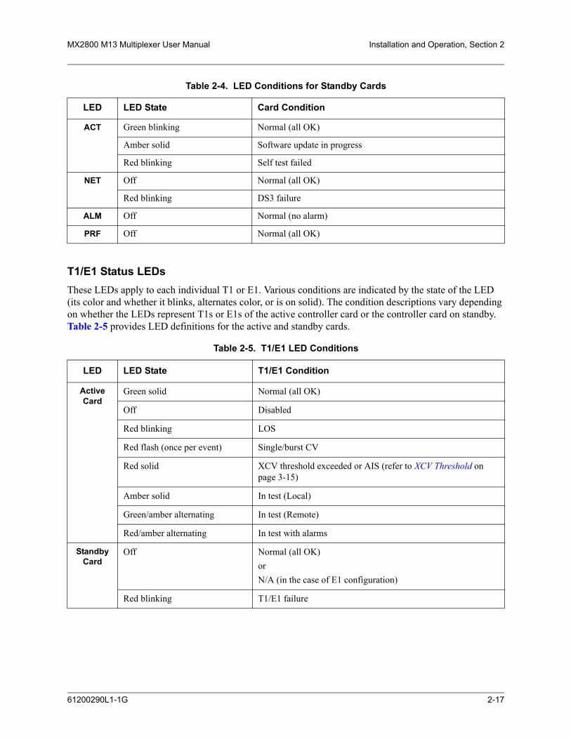
MX2800 M13 Multiplexer User Manual Installation and Operation, Section 2
T1/E1 Status LEDsThese LEDs apply to each individual T1 or E1. Various conditions are indicated by the state of the LED (its color and whether it blinks, alternates color, or is on solid). The condition descriptions vary depending on whether the LEDs represent T1s or E1s of the active controller card or the controller card on standby. Table 2-5 provides LED definitions for the active and standby cards.
Table 2-4. LED Conditions for Standby Cards
LED LED State Card Condition
ACT Green blinking Normal (all OK)
Amber solid Software update in progress
Red blinking Self test failed
NET Off Normal (all OK)
Red blinking DS3 failure
ALM Off Normal (no alarm)
PRF Off Normal (all OK)
Table 2-5. T1/E1 LED Conditions
LED LED State T1/E1 Condition
Active Card
Green solid Normal (all OK)
Off Disabled
Red blinking LOS
Red flash (once per event) Single/burst CV
Red solid XCV threshold exceeded or AIS (refer to XCV Threshold on page 3-15)
Amber solid In test (Local)
Green/amber alternating In test (Remote)
Red/amber alternating In test with alarms
Standby Card
Off Normal (all OK) or N/A (in the case of E1 configuration)
Red blinking T1/E1 failure
61200290L1-1G 2-17

Section 2, Installation and Operation MX2800 M13 Multiplexer User Manual
8. REPLACING OR INSTALLING CARDSThe MX2800 is designed with hot-swappable controller cards and power supplies. To replace or install a controller card or power supply, remove the front cover of the MX2800 with a phillips head screwdriver. Once the front of the MX2800 has been removed, the power supply and controller card slots will be visible. The two power supplies are located at the left of the chassis, and the controller cards are stacked on the right side of the chassis. To remove a card, use the locking lever(s) to pull the backplane connector away from the backplane. Once the backplane connector has been disconnected, carefully pull the card straight out of the chassis. To replace or install a card, line up the card with the guide grooves and carefully insert the card into the chassis until the backplane connector reaches the backplane. Finally, use the locking levers to seat the card all the way into the slot of the chassis. Once all cards have been replaced or installed, replace the front cover of the MX2800. Figure 2-11 shows how to remove and replace the front cover.
Figure 2-11. Replacing or Installing Cards
2-18 61200290L1-1G
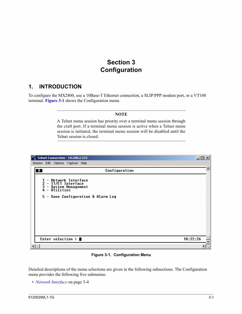
SECTION 3, CONFIGURATION
Section 3Configuration
1. INTRODUCTIONTo configure the MX2800, use a 10Base-T Ethernet connection, a SLIP/PPP modem port, or a VT100 terminal. Figure 3-1 shows the Configuration menu.
NOTEA Telnet menu session has priority over a terminal menu session throughthe craft port. If a terminal menu session is active when a Telnet menusession is initiated, the terminal menu session will be disabled until theTelnet session is closed.
Figure 3-1. Configuration Menu
Detailed descriptions of the menu selections are given in the following subsections. The Configuration menu provides the following five submenus:
• Network Interface on page 3-4
61200290L1-1G 3-1
Section 3, Configuration MX2800 M13 Multiplexer User Manual
• T1/E1 Interface on page 3-8
• System Management on page 3-16
• Utilities on page 3-38
• Save Configuration and Alarm Log on page 3-44
Figure 3-2 on page 3-3 shows the Configuration menu tree.
3-2 61200290L1-1G

MX2800 M13 Multiplexer User Manual Configuration, Section 3
Figure 3-2. Configuration Menu Tree
Network Interface
T1/E1 Interface
Utilities
M13
C-BIT*
Local
Loop*
Shutdown Standby
Loopback Time Out
B
A
Enabled
Disabled*
Enabled
Auto Enable*
Disabled
CSU
NIU
Disabled*
Save Configuration & Alarm Log
StateT1 # 1-28
T1 # 1-28
T1 # 1-28
T1 # 1-28
Loopback Detection
Line Coding
Timing
Remote Loopbacks
Framing
XCV Threshold
Circuit Protection
Line Identification
XCV ThresholdB8ZS*
AMI
FEAC/C-BIT*
FEAC
C-BIT
Disabled
IE-3
IE-4
IE-5
Disabled*
IE-6
IE-3
IE-4
IE-5
Disabled*
IE-6
Equipment Identification
Syslog Setup
Auto Save
Alarm Relay Configuration
Craft baud rate
Server IP Address
Refresh Period
DST Automatic Adjustment
State
Local Time Zone
1 min.
5 min.*
10 min.
Disabled
15 min.
30 min.
45 min.
1 hour
Line Length
DS3 Configuration
Protection Configuration
DS2 ConfigurationDS2 1-7
Miscellaneous
Active Controller
Max Switch Threshold (3)*
Network Protection
Min Switch Period (10)*
System Management
Mgmt Options
System Security
Date & Time
Miscellaneous
SNMP Mgmt Options
Trap IP Address
Write Community Name
Trap Generation
Trap Community Name
SNMP State
Read Community Name
Controller Traps
DS2 Alarm Traps
Power Supply Alarm Traps
T1/E1 Alarm Traps
MIB II Standard Alarm Traps
DS3 Alarm Traps
Radius State
Privilege Level
Server IP Address
Shared Secret Visibility
Shared Secret
UDP Port
Local IP Address
Gateway IP Address
Subnet Mask
Forward IP to Remote DS3
DS3 Remote IP Address
DS3 IP MTU
Dialup Options (List 1)
Management Port
Modem Rmt IP Addr (List 1)
Load Default Settings
System Reset
Update FLASH Software
Configuration Transfer
133-266 ft.
266-399 ft.
399-533 ft.
0-133 ft.*
533-655 ft.Enabled*
Disabled
Local User Accounts
Radius Mgmt options
Time
Date
T1 # 1-28
T1 # 1-28
Update via TFTP Server
Update via XMODEM
Terminal Timeout
User Account Management
IP Hosts
IP Security
* = default settings
Network Date/ Time Options
Load Default settings OTHER THAN system management
Load SYSTEM MANAGEMENT default settings
Load ALL default settings
Auto Enable Delay
Maximum Retries
Response Timeout
System Name
61200290L1-1G 3-3

Section 3, Configuration MX2800 M13 Multiplexer User Manual
2. NETWORK INTERFACESelect Network Interface to access the network configuration parameters. See Figure 3-3. Configure the MX2800 network settings to match the DS3 signal received from the service provider.
Figure 3-3. Network Configuration Menu
DS3 ConfigurationThe DS3 Configuration selections are used to configure the DS3 network settings to match the desired application. Descriptions of these settings are explained below.
FramingThe framing format is used to match the format of the receive signal at the network interface. The MX2800 supports C-bit and M13 framing formats.
NOTEM13 may not be selected when IP Forwarding is active.
Line LengthThe line length is set to reflect the physical length of the DS3 network line.
• Long should be used if the cabling distance exceeds 225 feet.
• Short should be used if the distance is less than 225 feet.
3-4 61200290L1-1G
MX2800 M13 Multiplexer User Manual Configuration, Section 3
NOTEFirst and second generation DS3 controller cards (P/N 1200288Lx and P/N 1202288Lx) use Long for distances over 50 feet and Short for distancesunder 50 feet.
NOTEFifth generation DS3 controller cards (P/N 1205288Lx) do not require aDS3 line length setting; therefore, Line Length does not appear as a menuitem.
TimingWhen the MX2800 is connected to a network that provides timing, configure the MX2800 for LOOP timing to derive timing from the network. If the MX2800 is the master timing source for the circuit, configure the MX2800 to LOCAL. In applications where two MX2800s are connected back-to-back with an un-channelized DS3, configure one MX2800 to LOOP and one MX2800 to LOCAL.
Remote LoopbacksThe following four options are available for remote loopbacks:
• FEAC/C-BIT is used to allow the MX2800 to respond to remote loopback requests received over either the DS3 Far End Alarm and Control (FEAC) channel and/or DS2-level C bits. This mode is valid in both C-BIT and M13 framing formats.
• FEAC is used to allow the MX2800 to respond only to remote loopback requests received over the DS3 FEAC channel. This mode is valid only when using C-BIT framing. In this mode, DS2 C-bit loopbacks will be ignored.
• C-BIT is used to allow the MX2800 to respond only to remote loopback requests received over DS2 C bits. This mode is available when operating in either C-BIT or M13 framing. In this mode, FEAC loopbacks received when operating in C-BIT framing will be ignored.
• Disabled is used to ignore all out-of-band loopback requests (FEAC and DS2 C-BIT). When Disabled is selected, the MX2800 will still respond to individual T1 in-band CSU/NIU loopbacks if so configured in the T1/E1 Loopback Detection menu.
NOTEChoose FEAC/C-BIT via menus in either C-BIT or M13 framing modes;however, there is no FEAC channel when framing is set to M13.Therefore, no DS3 far end alarms or loopback requests via the FEAC willbe valid when the MX2800 is configured for M13.
61200290L1-1G 3-5

Section 3, Configuration MX2800 M13 Multiplexer User Manual
XCV ThresholdExcessive code violations (XVC) Threshold sets a limit on CVs accepted by the unit before it switches controller cards. If set to Disabled, code violations will not cause the unit to switch controller cards. The threshold limits are described in Table 3-1.
Protection ConfigurationThe MX2800 houses two controller cards for 1:1 protection against hardware failure. The two cards can also provide network protection, supporting two T3 circuits simultaneously. The selections in this menu allow customizing the unit’s protection setup.
Active ControllerThis field displays A or B, indicating the active controller card. This setting can be used to force the controller cards to switch. For example, if controller card A is active and B is selected, a switch-over occurs immediately.
Network ProtectionThis field enables or disables the unit’s ability to automatically route information to the backup T3 in the event of a primary T3 failure. If enabled, all information is automatically routed to the backup T3. If disabled, the stand-by controller protects against failures of the active controller.
Maximum Switch ThresholdThe value entered in this field determines the number of times per hour the unit is allowed to switch between controller cards. If, in an hour, the cards switch more than the Maximum Number of Switches, the unit issues a trap and stops switching cards for the next 24 hours. Refer to Trap Descriptions on page 3-22. The default setting is three times an hour. This count may be cleared by clearing Protection Switch alarm counts. See Figure 5-13 on page 5-14.
Min. Switching PeriodAfter the unit switches controller cards, the number of seconds entered in this field must pass before another card switch will be allowed. The default setting is 10 seconds.
Table 3-1. XCV Threshold Limits
Setting The unit switches controller cards if...
1E-3 More than one out of every 1,000 bits received on the DS3 contains a code violation
1E-4 More than one out of every 10,000 bits received on the DS3 contains a code violation
1E-5 More than one out of every 100,000 bits received on the DS3 contains a code violation
1E-6 More than one out of every 1,000,000 bits received on the DS3 contains a code violation
3-6 61200290L1-1G

MX2800 M13 Multiplexer User Manual Configuration, Section 3
MiscellaneousThe Miscellaneous menu selections are used to configure the Loopback Timeout and Shutdown Stand-by settings. Descriptions of these settings are explained below.
Loopback TimeoutThe Loopback Timeout option is used to set the loopback timeout to one of the following:
• Disabled
• 1 min.
• 5 min.
• 10 min.
• 15 min.
• 30 min.
• 45 min.
• 1 hr.
• 120 min.
Shutdown Stand-By
The Shutdown Stand-by option causes the system to disable the standby controller card, thus making it unavailable for protection switches. Once this option has been selected and the standby controller has been shut down, the option changes to Reset Stand-by. Selecting this option resets and reactivates the standby controller, thus making it available for protection switching.
DS2 ConfigurationThe MX2800 can individually frame each of the seven DS2 streams in M12 (four T1s) or G.747 (three E1s) format. When set to M12 (4xT1), the four T1s for the selected group are framed per ANSI T1.107. When set to G.747 (3xE1), the first three T1/E1 ports of the selected group are framed per CCITT G.747 into the DS3 stream. The fourth T1/E1 port of the selected group is not available in this mode. Any combi-nation of M12 (4xT1) and G.747 (3xE1) is allowed.
61200290L1-1G 3-7

Section 3, Configuration MX2800 M13 Multiplexer User Manual
3. T1/E1 INTERFACEThe T1/E1 Interface menu, see Figure 3-4, is used to activate/deactivate individual T1s and E1s and to set their line coding, length, loopback detection, circuit protection, and line ID string. The T1/E1 code viola-tion threshold is also configured through this menu. Configuration selections are described in the following sections.
NOTEA DS2 can be divided into either three E1s or four T1s. Therefore, whendealing with an E1 configuration, some of the fields in the T1/E1Interface menus do not apply (and therefore display N/A).
Figure 3-4. T1/E1 Interface Menu
3-8 61200290L1-1G

MX2800 M13 Multiplexer User Manual Configuration, Section 3
T1/E1 StateThe T1/E1 lines are set to Disabled, Enabled, or Auto Enable. In Auto Enable, the port is not fully enabled (and alarms are not issued) until a T1/E1 signal is detected on that port’s receiver for a specified period of time. See Figure 3-5 on page 3-9. This period of time is set by the Auto Enable Delay option. The options are as follows:
• 2 seconds (default)
• 1 hour
• 2 hours
• 12 hours
• 1 day
• 2 days
• 7 days
Figure 3-5. T1/E1 State Menu
Set MultipleThe Set Multiple, see Figure 3-6 on page 3-10, option is used to enable or disable a contiguous group or all of the T1/E1s at one time. To enable or disable all T1/E1s, set First to 1 and Last to 28. Enter Apply settings before leaving the menu. To enable or disable only some of the T1/E1s, set First and Last to correspond to the desired lines. Enter Apply settings. Either leave the menu at this point or continue to enter new First and Last numbers for other lines.
61200290L1-1G 3-9

Section 3, Configuration MX2800 M13 Multiplexer User Manual
NOTESettings should be applied following each change.
Figure 3-6. Set Multiple Menu
T1/E1 Line CodingSet the line code for each individual T1/E1 interface to match the connected device. See Figure 3-7 on page 3-11. The choices available for T1 are AMI and B8ZS. The choices available for E1 are AMI and HDB3. Select Set Multiple to set a contiguous group or all of the T1s (or E1s) to the same value at the same time. Refer to Set Multiple on page 3-9 for a description of the Set Multiple option.
3-10 61200290L1-1G

MX2800 M13 Multiplexer User Manual Configuration, Section 3
Figure 3-7. T1/E1 Line Coding Menu
T1/E1 Line LengthSet the line length for each T1 interface according to the distance from the MX2800 to the connecting DSX termination. See Figure 3-8 on page 3-12. The E1 Line Length is not selectable and remains at 0-6 dB loss. Select Set Multiple to configure the line length for a contiguous group or all of the T1s to the same length at the same time. Refer to Set Multiple on page 3-9 for a description of the Set Multiple option.
61200290L1-1G 3-11
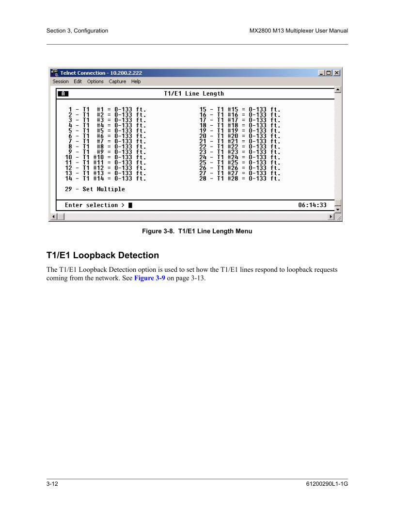
Section 3, Configuration MX2800 M13 Multiplexer User Manual
Figure 3-8. T1/E1 Line Length Menu
T1/E1 Loopback DetectionThe T1/E1 Loopback Detection option is used to set how the T1/E1 lines respond to loopback requests coming from the network. See Figure 3-9 on page 3-13.
3-12 61200290L1-1G
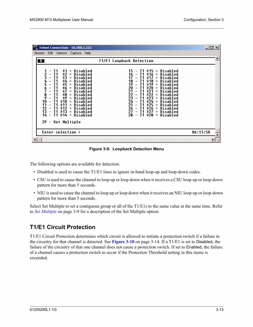
MX2800 M13 Multiplexer User Manual Configuration, Section 3
Figure 3-9. Loopback Detection Menu
The following options are available for detection:
• Disabled is used to cause the T1/E1 lines to ignore in-band loop-up and loop-down codes.
• CSU is used to cause the channel to loop up or loop down when it receives a CSU loop-up or loop-down pattern for more than 5 seconds.
• NIU is used to cause the channel to loop up or loop down when it receives an NIU loop-up or loop-down pattern for more than 5 seconds.
Select Set Multiple to set a contiguous group or all of the T1/E1s to the same value at the same time. Refer to Set Multiple on page 3-9 for a description of the Set Multiple option.
T1/E1 Circuit ProtectionT1/E1 Circuit Protection determines which circuit is allowed to initiate a protection switch if a failure in the circuitry for that channel is detected. See Figure 3-10 on page 3-14. If a T1/E1 is set to Disabled, the failure of the circuitry of that one channel does not cause a protection switch. If set to Enabled, the failure of a channel causes a protection switch to occur if the Protection Threshold setting in this menu is exceeded.
61200290L1-1G 3-13

Section 3, Configuration MX2800 M13 Multiplexer User Manual
Figure 3-10. Circuit Protection Menu
The Protection Threshold setting determines how many of the Enabled lines must fail before a card switch occurs. If the failure of a single protected (enabled) line is to cause a card switch, set the Protection Thresh-old to 1. Choices include 1 through 28.
Select Set Multiple to set a contiguous group or all of the T1/E1s to the same value at the same time. Refer to Set Multiple on page 3-9 for a description of the Set Multiple selection.
T1/E1 Line IdentificationThis field is used to enter user-configurable text strings to name the individual T1/E1 lines. See Figure 3-11 on page 3-15. This field will accept up to 18-alphanumeric characters, including spaces and special characters.
3-14 61200290L1-1G

MX2800 M13 Multiplexer User Manual Configuration, Section 3
Figure 3-11. Line Identification Menu
XCV ThresholdThis value sets a limit on excessive code violations (ECVs) accepted by the unit over an individual T1/E1 line before it switches controller cards. If set to Disabled, code violations will not cause the unit to switch controller cards. The threshold limits are described in Table 3-2.
Table 3-2. XCV Threshold Limits for T1/E1
Setting The unit switches controller cards if...
1E-3 More than one out of every 1,000 bits received on a T1/E1 line contains a code violation
1E-4 More than one out of every 10,000 bits received on a T1/E1 line contains a code violation
1E-5 More than one out of every 100,000 bits received on a T1/E1 line contains a code violation
1E-6 More than one out of every 1,000,000 bits received on a T1/E1 line contains a code violation
61200290L1-1G 3-15

Section 3, Configuration MX2800 M13 Multiplexer User Manual
4. SYSTEM MANAGEMENTConfigure the MX2800 for management through SNMP, Telnet, or a VT100 interface. See Figure 3-12 on page 3-16. Embedded SNMP and Telnet are available via a SLIP/PPP modem port or 10Base-T Ethernet interface. This menu also includes options used to customize the unit’s alarm and trap generation, security setup, and equipment identification. The fields of the System Management Configuration menu vary depending upon the configuration of the options in the shelf.
Figure 3-12. System Management Configuration Menu
CAUTIONConfiguration changes to Local IP Address, Gateway IP Address, SubnetMask, and IP Hosts will not be implemented unless all Telnet sessions areclosed. Changes made while Telnet sessions are active will invoke awarning message on the console.
NOTEIf the unit is not equipped with an internal modem, Dialup Option will notbe available.
3-16 61200290L1-1G
MX2800 M13 Multiplexer User Manual Configuration, Section 3
Management OptionsThe Management options sets the fields that allow SNMP, Telnet, or VT100 interface access. The options are listed below.
Local IP AddressThis field is used to enter the MX2800 IP address. This IP address applies to the LAN or modem port when configured for SLIP/PPP. This address is available from a network administrator.
Gateway IP AddressThis field is used to enter the gateway IP address of the MX2800. This address is necessary only if the MX2800 and the network manager are connected through a gateway node. If an IP packet is to be sent to a different network, the unit sends it to the gateway.
Subnet MaskThis field is used to enter the subnet mask of the MX2800. This address is available from a network admin-istrator.
Modem Remote IP AddressThis field is used to enter the IP address of a server that accesses the MX2800 via a modem over PPP or SLIP. This option is available only if the Management Port is set to LAN + MODEM or DS3 + MODEM.
Management PortThis field is used to assign the management port as either LAN, MODEM, LAN+MODEM, DS3, or DS3+MODEM. The Modem setting applies only to units equipped with an internal modem.
Forward IP to Remote DS3This field is used to enable or disable the IP forwarding feature that allows IP access to a remote MX2800 across the DS3 channel. With this feature, the far-end MX2800 appears as if it is on the same LAN as the near-end MX2800. To access any IP related feature on the far-end unit, address packets to the IP address of the far-end unit.
NOTEIf the near-end and far-end MX2800s are currently on the same LAN, it isimportant to configure the far-end MX2800 Management Port option forDS3 or DS3 + MODEM before enabling Forward IP To Remote DS3 onthe near-end unit. Doing so prevents multiple MAC addresses from beingassociated with the same IP address in the networks ARP tables.
61200290L1-1G 3-17
Section 3, Configuration MX2800 M13 Multiplexer User Manual
NOTEThe DS3 must be up and running error-free and using C-Bit framing (thisfeature will not work with M13 framing). The Management Port optionfor the near-end unit (one connected to the Ethernet LAN) must be set toeither LAN or LAN + MODEM. A valid IP Address, Subnet Mask, andDefault Gateway must be entered for the near-end unit.
DS3 Remote IP AddressIf Forward IP to Remote DS3 is Enabled, set the DS3 Remote IP Address to a valid IP address on the same subnet as the near-end unit. All packets that are sent to this IP address will be forwarded across the DS3 channel to the far-end unit.
NOTEThe IP Address of the remote unit must be the same as the one that isentered for the DS3 Remote IP Address in the near-end unit's menus. TheManagement Port option for the far-end unit must also be set to DS3 orDS3+MODEM to be managed remotely over the DS3. The Subnet Maskand Default Gateway do not need to be set in the far-end unit's menus.The DS3 Remote IP Address must be on the same subnet as the Local IPAddress.
DS3 IP MTUThis field is used to select the maximum IP datagram size (in bytes) for the IP forwarding link over the DS3. This option should be left at it default and preferred value of 260. If and only if the device on the other side of the DS3 facility is an ADTRAN device that also has this option, then both side can be set to 1500 to avoid fragmentation of large packets. Otherwise, leave the setting at 260 to avoid lost packets.
Dialup OptionsThis field is used to configure the dialup capabilities of the MX2800. See Figure 3-13. These options apply only to units equipped with an internal modem.
3-18 61200290L1-1G

MX2800 M13 Multiplexer User Manual Configuration, Section 3
Figure 3-13. Dialup Options Menu
Primary and Secondary Phone Numbers
When the MX2800 dials out to send a trap, it first dials the Primary Phone Number. If the call is unsuccess-ful, it tries the Secondary Phone Number. Attempts between the two numbers continue until a call is estab-lished and the trap is reported (or until each number’s maximum for redial attempts is reached). Refer to Maximum Redial Attempts on page 3-19.
Initializing String
The AT command entered in this field is used to initialize the modem. Normally, this field should be left at the default setting (ATZ).
Dial String
The AT command entered in this field causes the modem to dial out. Normally, this field should be left at the default setting (ATDT).
Maximum Redial Attempts
The MX2800 attempts to establish a call the number of times entered in this field. If a successful call is not established after the final attempt, the MX2800 discards the trap messages.
Idle Timeout
After establishing a call and sending trap messages, the MX2800 remains online for the amount of seconds entered in this field. If the field is set to 0, the unit hangs up as soon as the trap is sent.
61200290L1-1G 3-19

Section 3, Configuration MX2800 M13 Multiplexer User Manual
Connection Timeout
The MX2800 waits for a connection for the number of seconds entered in this field. Timing begins as soon as the dial command is issued. This field must be set for greater than 20 seconds.
Pause Between Calls
The MX2800 waits between redial attempts for the number of seconds entered in this field.
Dialout On Trap
This field is used to enable or disable the MX2800’s ability to dial out to report traps. Modem Mode configured for VT-100 reports error conditions in plain ASCII with the following information:
• The Unit ID value programmed in the Equipment Identification portion of the System Management screen. Refer to System Management on page 3-16.
• A trap code indicating the error condition
• A text description of the fault
• The date and time when the error was logged
When Modem Mode is configured for PPP or SLIP, the MX2800 logs into the PPP/SLIP host and reports the error conditions to the hosts designated under Trap IP Addresses. Refer to Trap IP Addresses on page 3-21.
Answer on Ring
This option enables or disables the MX2800’s ability to accept incoming calls. If enabled, incoming calls are automatically answered by the MX2800, allowing remote performance of management functions.
Modem Mode
This field is used to select the Modem port function for the desired application (VT-100, PPP, or SLIP). The Modem port, located on the rear panel of the MX2800, provides a telephone line (POTS) for connec-tion to the internal V.34 modem. This setting applies only if the Management Port is set to Modem. Refer to Management Port on page 3-17.
Modem Baud Rate
This option is used to set the maximum operating speed in bps of the Modem port:
• 1200
• 2400
• 4800
• 9600
• 19200
• 38400
3-20 61200290L1-1G

MX2800 M13 Multiplexer User Manual Configuration, Section 3
Hangup
Selecting this option forces the MX2800 to end an established call.
Last Modem Response
This status field displays the last modem response to the MX2800. Possible responses are as follows:
• OK
• Connect
• Busy
• Error
• No Dialtone
• No Carrier
SNMP Management Options
SNMP StateUse this menu to Enable or Disable SNMP for the MX2800. When disabled, the MX2800 ignores all incoming SNMP packets and does not transmit SNMP packets.
Trap IP AddressesThis field is used to enter up to five IP addresses of SNMP managers to which the MX2800 sends traps.
Trap GenerationUse this menu, see Figure 3-14, to designate which error conditions cause the unit to send trap messages.
61200290L1-1G 3-21

Section 3, Configuration MX2800 M13 Multiplexer User Manual
Figure 3-14. Trap Generation Menu
Table 3-3 provides trap descriptions.
Table 3-3. Trap Descriptions
Trap If enabled, the unit issues a trap when...
Controller Traps
Protection Switch The controller cards switch.
Card Removed A controller card has been removed.
Card Failure A controller card has failed.
Communication Fail The controller cards can no longer communicate with each other.
Max Switches The Max Switch Threshold is reached. For more information, refer to Maximum Switch Threshold on page 3-6.
Power Supply Alarm Traps
Card Removed The power supply card has been removed.
Malfunction The power supply card is no longer working and the unit has switched to the backup power supply or battery backup.
Card Failure The power supply card has failed.
Power Low The power supply’s output level is abnormally low.
Bat. Backup Act Battery charger has lost its AC power source.
3-22 61200290L1-1G

MX2800 M13 Multiplexer User Manual Configuration, Section 3
Battery Low Battery backup has reached an energy point insufficient to supply the unit with power.
Temperature High The power supply card is getting too hot.
Temperature Critical The power supply card temperature is so high that it may suffer damage.
DS3 Alarm Traps (Near-End Active and Standby Cards)
LOS The controller card has lost the network Rx signal.
OOF The controller card detects a framing loss from the network.
AIS The controller card is receiving an AIS (blue) alarm condition from the network. AIS alarms occur when consecutive 1010s are received in the information bits. This indicates that The controller card is receiving an AIS (blue) alarm condition from the network. This alarm occurs when consecutive 1010s are received in the information bits, indicating there is a transmission fault located either at or upstream from the transmitting terminal.
RAI The controller card is receiving an RAI (yellow) alarm from the network. This alarm is a signal sent back toward the source of a failed transmit circuit. The X-bits (X1 and X2) are set to zero.
IDLE The controller card detects an idle sequence from the network.
TX LOS The controller card’s transmitter has failed.
XCV The controller card is receiving excessive code violations, exceeding the threshold set by the user. For more information, refer to XCV Threshold on page 3-6.
In/Out Test The DS3 is going in and out of test (applies to the Active controller card only).
DS3 Alarm Traps (Far-End Active Cards)
LOS The remote unit’s active controller card has lost the network Rx signal.
OOF The remote unit’s active controller card detects a framing loss from the network.
AIS The remote unit’s active controller card is receiving an AIS (blue) alarm condition from the network.
RAI The remote unit’s active controller card is receiving an RAI (yellow) alarm from the net-work. This alarm is a signal sent back toward the source of a failed transmit circuit. The X-bits (X1 and X2) are set to zero.
IDLE The remote unit’s active controller card detects an idle sequence from the network.
DS3 Eqpt Fail SA The remote unit’s active controller card is receiving a service-affecting equipment failure message from the network.
DS3 Eqpt Fail NSA The remote unit’s active controller card is receiving a non-service-affecting equipment failure message from the network.
Table 3-3. Trap Descriptions (Continued)
Trap If enabled, the unit issues a trap when...
61200290L1-1G 3-23

Section 3, Configuration MX2800 M13 Multiplexer User Manual
Read Community NameThis field is used to enter the authentication strings used for SNMP management. Match the MX2800 to the SNMP manager for read privileges.
Comn Eqpt Fail NSA The remote unit’s active controller card is receiving a common equipment failure mes-sage from the network.
DS2 Alarm Traps
OOF The DS2 detects a framing loss from the network.
AIS The DS2 is receiving an AIS (blue) alarm condition from the network. AIS alarms occur when the unit is receiving unframed all ones.
RAI The DS2 is receiving an RAI (yellow) alarm from the network. This alarm is a signal sent back toward the source of a failed transmit circuit. The X-bit is set to zero.
Local T1/E1 Alarm Traps
LOS The unit has lost the Rx signal on a T1/E1.
carrier side AIS (CAIS)
The T1 is receiving all ones from the DS3 side of the network.
loop side AIS (LAIS) The T1 is receiving all ones from the DSX-1 interface.
XCV The unit is receiving excessive code violations across a T1/E1, exceeding the configured threshold. For more information, refer to XCV Threshold on page 3-15.
T1/E1 Failure A T1/E1 has failed.
In/Out Test A T1/E1 is going in or out of test.
Far-End Alarms (available only in C-Bit Parity mode)
Multiple DS1 LOS The far-end equipment has lost multiple T1/E1 lines.
Single DS1 LOS The far-end equipment has lost a single T1/E1.
DS1 Eqpt Fail SA A service-affecting equipment failure is being reported by the far-end.
DS1 Eqpt Fail NSA A non-service-affecting equipment failure is being reported by the far-end.
MIB II Standard Alarm Traps
Cold Start The unit is first powered up.
Link Up The DS3 is up with no alarms.
Link Down The DS3 is in alarm.
Authentication Fail-ure
An attempt has been made by an unauthorized user to access the unit.
Table 3-3. Trap Descriptions (Continued)
Trap If enabled, the unit issues a trap when...
3-24 61200290L1-1G

MX2800 M13 Multiplexer User Manual Configuration, Section 3
Write Community NameThis field is used to enter the authentication strings used for SNMP management. Match the MX2800 to the SNMP manager for write privileges.
Trap Community NameThis field is used to enter the identification string used for trap management. This string accompanies all traps transmitted by the MX2800.
System NameThis value is equivalent to the sysName item defined in RFC1213. The value is an administratively-assigned name for the managed node. By convention, this is the node's fully-qualified domain name.
Network Date/Time OptionThe MX2800 is capable of having the date and time provisioned from a remote server using one of two supported protocols: SNTP version 3 (per RFC1769) and Network Time (per RFC868).
Several options are available for provisioning this feature, all of which are accessible only via menus by users with Admin-level privileges. These options reside in the System Management menu.
StateThis option sets the mode or protocol used to retrieve the date and time from the server. Possible values are Disabled, SNTP, and Net Time. When the State option is set to Disabled, the user should explicitly set the date and time locally (via menus, TL1, or SNMP). If the State option is set to SNTP or Net Time, then the product prevents any attempt to set the time locally. The default value is Disabled.
Server IP AddressThis option sets the IP address of the server to be queried for the date and time.
Refresh PeriodThis option sets the length of time between queries to the server. The available values range are as follows:
• 1 minutes interval
• 5 minutes interval
• 10 minutes interval
• 15 minutes interval (default)
• 20 minutes interval
• 25 minutes interval
• 30 minutes interval
• 35 minutes interval
61200290L1-1G 3-25

Section 3, Configuration MX2800 M13 Multiplexer User Manual
• 40 minutes interval
• 45 minutes interval
• 50 minutes interval
• 55 minutes interval
• 60 minutes interval
DST Automatic AdjustmentThis option sets automatic adjustment for North American daylight saving time. Available values are Enabled and Disabled. The default value is Enabled. This automatic adjustment is performed only in association with responses from the server. The automatic adjustment does not take place if the State option is disabled and/or if the server cannot be contacted.
Local Time ZoneThis option sets the time zone in which the MX2800 unit is located. Possible values consist of North American time zones from Hawaii-Aleutian Standard Time to Atlantic Standard Time. The default value is Eastern Standard Time.
NOTEThe MX2800 processes only the Transmit Timestamp value of all SNTPresponse messages. Other constructs supported by the protocol (such asroot delay, root dispersion, authentication, etc.) are not processed by theMX2800.
System Security
User Account ManagementThis option is used to enter up to 15 user accounts. Each user account is assigned a username, password, and privilege level. Usernames and passwords are not case sensitive but must be 12 characters or less. Each user account is assigned a privilege level to provide the option of limiting a user's access to the MX2800. The four privilege levels are listed below.
Guest
A user with this read-only privilege level can view almost all menu items on the console interface menus and can perform a limited number of TL1 commands, none of which can alter the product's configuration.
Interface
A user with write-access privilege level can configure items related to the network interface and T1/E1 interface but can not initiate loopbacks and view and/or alter several system-level items such as LAN configurables.
3-26 61200290L1-1G

MX2800 M13 Multiplexer User Manual Configuration, Section 3
Test
A user with write-access privilege level can configure the network interface and T1/E1 interface and can initiate loopbacks but may not view and/or alter several system-level items such as LAN configurables, etc.
Admin
With Admin privilege level, all menu items can be viewed and/or altered. Only a user with an Admin user account can alter the User Account Management information.
User accounts provide access to the MX2800 for console interface sessions and TL1 sessions. Table 3-4 on page 3-30 provides a summary of privileges.
NOTEThe Load Default Settings menu item that is located on the Configuration/Utilities menu resets the User Account Management table back to thefactory default account adtran/adtran/admin.
RADIUS AuthenticationThe MX2800 is capable of communicating with a RADIUS server for authentication of menu users and TL1 users. The RADIUS authentication support is implemented per RFC2865. User account information in the onboard user database will remain intact when the MX2800 is upgraded to support authentication via RADIUS.
Several options are available for provisioning RADIUS authentication features, all of which are accessible only via menus and by users with Admin-level privileges.
RADIUS State
This option sets the RADIUS authentication capabilities as either Enabled or Disabled. The default value is Disabled.
When the RADIUS State value is Enabled, the following behavior applies when a user enters a username and password at the MX2800. The MX2800 first authenticates the username and password against the local user database. If local authentication succeeds, then access is granted to the MX2800 with the privi-lege level assigned for that account in the onboard database. Local authentication is considered successful if both the username and password are authenticated, regardless of the privilege level (including Disabled).
If local authentication does not succeed, then the username and password are authenticated against the RADIUS server. If the RADIUS authentication succeeds, then access to the MX2800 is granted with the RADIUS Privilege Level set by the user. If the RADIUS authentication does not succeed, which includes the case where the MX2800 does not receive a response from the server, then the user is denied access to the MX2800.
Regardless of whether the RADIUS State option is Enabled or Disabled at the MX2800, each user account that exists in the local user database may be assigned one of the defined privilege levels for the MX2800 (Disabled, Guest, Interface, Test, or Admin). Only a user with the Admin privilege level can access the local database and the RADIUS options.
61200290L1-1G 3-27
Section 3, Configuration MX2800 M13 Multiplexer User Manual
Usernames and passwords stored in the local user database are each limited to 11 ASCII characters. Usernames and passwords authenticated via RADIUS may each have up to 63 ASCII characters.
When RADIUS authentication is disabled, safeguards are in place that will prevent an Admin-level user from deleting all Admin-level accounts in the onboard user database. When RADIUS authentication is enabled, an Admin-level user who was authenticated through RADIUS will be allowed to delete all of the onboard accounts. This will be allowed to avoid some potential security concerns.
Safeguards will exist that will prevent certain combinations of options involving RADIUS and the local user database that would effectively remove all means of accessing the MX2800 with Admin privileges.
The recovery mechanism for gaining access via the challenge password (ADTRANPLEASEHELP) is supported regardless of whether the RADIUS authentication option is enabled or disabled. When a user enters this password, the MX2800 issues a unique challenge sequence that requires a response provided by ADTRAN Tech Support for access to the unit.
Local user accounts and passwords for the MX2800 are not case-sensitive. However, case is preserved for both username and password when authenticating through RADIUS. The TL1 input message specification limits the characters that may be sent as part of a TL1 command, unless the string is enclosed in double quotes. This is important when RADIUS authentication is used for authenticating TL1 sessions. Passwords or usernames with special characters must be placed in double quotes in the ACT-USER command. If double quotes appear inside the TL1 username or password, each double quote character must be immedi-ately preceded by the backslash character to avoid confusion with the double quotes surrounding the username or password.
The MX2800 supports Challenge response messages from the RADIUS server regardless of whether the login attempt is made via menus or TL1. If a Challenge response is received from the server, then the user is prompted for additional information. The nature of this additional information is application-dependent. When the Challenge response is received during an attempt to log in via TL1, then a PLNA TL1 response is returned to the user and the Challenge message is provided in the TL1 comment field.
Server IP Address
This option sets the IP address of the server to be queried for authentication. The default value is a null IP address. One IP address is supported.
UDP Port
This option sets the UDP port of the server. The default value is 1812.
Privilege Level
This option sets a single privilege level that applies for all users that are granted access via remote authen-tication. The possible values are Disabled, Guest, Interface, Test, and Admin. The default value is Guest. Refer to the appropriate MX2800 documentation for explanations of these privilege levels.
Shared Secret Visibility
This option sets the visibility of the Shared Secret value as displayed in the provisioning menu for RADIUS authentication options. The possible values are Visible and Invisible. When this option is set to Invisible, the Shared Secret value is masked with asterisk characters. The default value is Invisible.
3-28 61200290L1-1G

MX2800 M13 Multiplexer User Manual Configuration, Section 3
Shared Secret
This option sets the shared secret that is used during the process of authenticating via the RADIUS server. This value is a case-sensitive ASCII character string that has a maximum length of 63 ASCII characters. The default value is a null string.
Response Timeout
This option sets the number of seconds the MX2800 will wait for a response before retransmitting the request.
Maximum Retries
This option sets the maximum number of retransmissions of an authentication request that the MX2800 will attempt in the absence of a response from the server.
61200290L1-1G 3-29

Section 3, Configuration MX2800 M13 Multiplexer User Manual
Table 3-4. Console Menu User Privileges
Console Menu Item
Privilege level(s) under which a user may alter (and in some cases, view) this item
Guest Interface Test Admin
Status Menu
Acknowledge alarms X X X
Statistics Menus
Clear statistics (for all Statistics menus) X X X
Reset alarm log X X X
Configuration – Network Interface Menu
DS3 framing mode X X X
DS3 line length (L1 Controller Card only) X X X
DS3 timing X X X
DS3 loopback detection X X X
DS3 XCV threshold X X X
Active controller X X X
Network protection X X X
DS3 max switch threshold X X X
DS3 min switching period X X X
Loopback time out X X X
Shutdown stand-by controller X X X
Reset stand-by controller X X X
DS2 #1-7 mode (T1 or E1) X X X
Configuration – T1/E1 Interface Menu
T1/E1 state X X X
T1/E1 line coding X X X
T1/E1 line length X X X
T1/E1 loopback detection X X X
T1/E1 circuit protection X X X
T1/E1 protection threshold X X X
T1/E1 line identification X X X
3-30 61200290L1-1G

MX2800 M13 Multiplexer User Manual Configuration, Section 3
T1/E1 XCV threshold X X X
Configuration – System Management Menu
Local IP address X
Gateway IP address X
Subnet mask X
Modem remote IP address (controller with modem) X
Management port X
Forward IP to remote DS3 X
DS3 remote IP address X
Dial-up Option menu (controller with modem) X
DS3 IP MTU X
System Name X
SNMP Management Option menu X
Network Date/Time Option menu X
User Account Management menu X
Terminal time out X
IP security X
IP hosts X
Date X
Time X
Alarm Relay Configuration menu X
Equipment ID menu X
Syslog Setup menu X
Save-on-logout X X X
Craft baud rate X X X
Telnet Client menu
IP Address X
Table 3-4. Console Menu User Privileges (Continued)
Console Menu Item
Privilege level(s) under which a user may alter (and in some cases, view) this item
Guest Interface Test Admin
61200290L1-1G 3-31

Section 3, Configuration MX2800 M13 Multiplexer User Manual
“X” denotes a privilege level that allows execution of the associated menu item.
TCP Port X
Connect X
Configuration – Utilities Menu
Load default settings X
Update flash software X
Configuration transfer X
System reset X
Configuration – Protection Switching Menu
Active controller X X X
Max switch threshold X X X
Min switching period X X X
Loopback Menu
T1/E1 loopbacks X X
DS2 loopbacks X X
DS3 loopbacks X X
Reset all tests X X
Clear BERR X X
Save Configuration & Alarm Log X X X X
Logout X X X X
Table 3-4. Console Menu User Privileges (Continued)
Console Menu Item
Privilege level(s) under which a user may alter (and in some cases, view) this item
Guest Interface Test Admin
3-32 61200290L1-1G
MX2800 M13 Multiplexer User Manual Configuration, Section 3
Terminal Time OutSet the amount of time the terminal or Telnet session remains inactive before automatically closing the session, requiring the user to log in again. Options include the following:
• Disabled
• 1 min.
• 5 min.
• 15 min.
• 60 min.
• 1 day.
IP SecurityEnable or disable the IP Security option. If IP Security is set to Enabled, the unit accepts management commands and Telnet sessions from the IP addresses entered into the IP Hosts fields.
IP HostsEnter up to 16 IP addresses of management stations from which the unit should accept management commands. These addresses are applicable only if IP Security is Enabled.
Date and TimeEnter date and time information. Enter the month, date, and year separated by forward slashes (02/23/04). Enter the time in military time separated by colons (13:15:25).
MiscellaneousThe Miscellaneous option of the System management menu sets the fields and values for the
• Alarm Relay Configuration
• Equipment Identification
• Syslog Setup
• Auto Save
• Craft baud rate
Alarm Relay ConfigurationThis menu enables and disables audible and visible alarms for specific error conditions. See Figure 3-15.
61200290L1-1G 3-33

Section 3, Configuration MX2800 M13 Multiplexer User Manual
Figure 3-15. Alarm Relay Configuration Menu
Table 3-5 describes the alarm conditions found in the Alarm Relay Configuration menu.
Table 3-5. Types of Alarms in Alarm Relay Configuration
Alarm Level Description
DS3 Alarms
RAI Critical The unit is receiving an RAI (yellow) alarm from the network. This alarm is a signal sent back toward the source of a failed transmit circuit. The X-bits (X1 and X2) are set to zero.
AIS Critical The unit is receiving an AIS (blue) alarm from the network. This alarm occurs when consecutive 1010s are received in the information bits, indicating the fault lies at or upstream from the transmitting source.
LOS Critical The unit has lost the network Rx signal.
LOF Critical The unit detects a framing loss from the network.
XCV Noncritical The controller card is receiving code violations in excess of the user specified threshold. Refer to XCV Threshold on page 3-15.
TLOS Critical The controller card transmitter has failed.
DS2 Alarms
RAI Noncritical The unit is receiving an RAI (yellow) alarm from the network across a DS2. This alarm is a signal sent back toward the source of a failed trans-mit circuit. The X-bits (X1 and X2) are set to zero.
AIS Noncritical The unit is receiving unframed all ones across a DS2.
3-34 61200290L1-1G

MX2800 M13 Multiplexer User Manual Configuration, Section 3
1. This is a critical alarm only when Inactive Card is not installed or is not working.2. T1/E1 alarms are cleared when the T1/E1 is disabled or set to Auto Enable after receiving an alarm.
Equipment IdentificationThese fields are used to store information that identifies the unit. See Figure 3-16 on page 3-36. Informa-tion provided for the far-end is read-only. Local information is read/write from this menu.
LOF Noncritical The unit detects a framing loss from the network across a DS2.
System Alarms
Controller Card A/B Fail
Critical Controller Card A/B has failed.1
Protection Switch Critical The unit detects a Controller Card protection switch. Data is routed from the primary to stand-by card.
Communication Fail Noncritical The Controller Cards can no longer communicate.
T1/E1 Alarms2
LOS Noncritical The unit has lost the receive signal on a T1/E1.
XCV Noncritical The controller card is receiving code violations in excess of the user specified threshold. Refer to XCV Threshold on page 3-15
Carrier Side AIS (CAIS)
Noncritical The T1 is receiving all ones from the DS3 side of the network.
Loop Side AIS (LAIS) Noncritical The T1 is receiving all ones from the DSX-1 interface.
Power Supply Alarms
Malfunction Noncritical Power supply card is no longer working. The unit has switched to the backup power supply or battery backup.
Power Low Noncritical Power supply’s output level is abnormally low.
Power Fail Noncritical Power supply card does not detect power input.
Bat. Backup Act Noncritical Battery charger has lost its AC power source.
Battery Low Noncritical Battery backup has reached an energy point insufficient to supply the unit with power.
Temperature High Noncritical Power supply card temperature is above normal.
Temperature Critical Noncritical Power supply card temperature is so high that it may suffer damage.
Table 3-5. Types of Alarms in Alarm Relay Configuration (Continued)
Alarm Level Description
61200290L1-1G 3-35
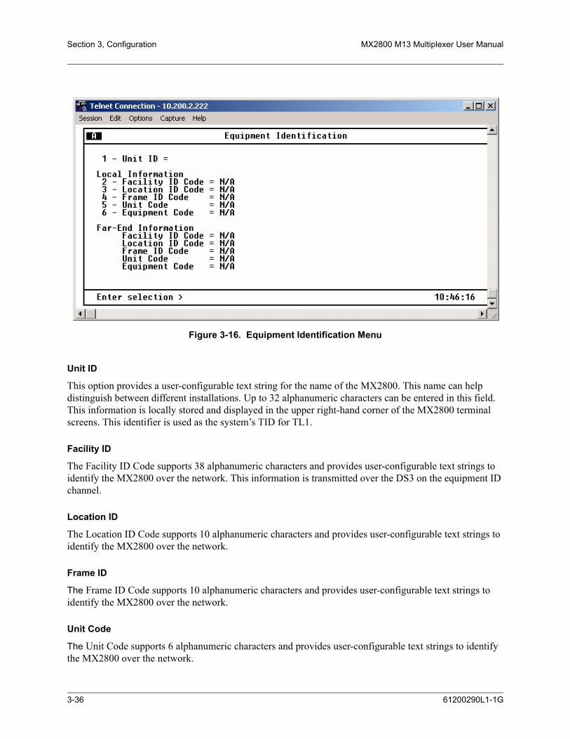
Section 3, Configuration MX2800 M13 Multiplexer User Manual
Figure 3-16. Equipment Identification Menu
Unit ID
This option provides a user-configurable text string for the name of the MX2800. This name can help distinguish between different installations. Up to 32 alphanumeric characters can be entered in this field. This information is locally stored and displayed in the upper right-hand corner of the MX2800 terminal screens. This identifier is used as the system’s TID for TL1.
Facility ID
The Facility ID Code supports 38 alphanumeric characters and provides user-configurable text strings to identify the MX2800 over the network. This information is transmitted over the DS3 on the equipment ID channel.
Location ID
The Location ID Code supports 10 alphanumeric characters and provides user-configurable text strings to identify the MX2800 over the network.
Frame ID
The Frame ID Code supports 10 alphanumeric characters and provides user-configurable text strings to identify the MX2800 over the network.
Unit Code
The Unit Code supports 6 alphanumeric characters and provides user-configurable text strings to identify the MX2800 over the network.
3-36 61200290L1-1G

MX2800 M13 Multiplexer User Manual Configuration, Section 3
Equipment Codes
The Equipment Code supports 10 alpha-numeric characters and provides user-configurable text strings to identify the MX2800 over the network.
Syslog SetupThese selections include Transmission, Host IP Address, Severity Level, and Host Facility.
Transmission
This option enables or disables the transmission of log events to the external Syslog server. The host IP address must be defined first.
Host IP Address
This option specifies the IP address of the external server that is running the Syslog host daemon.
Severity Level
This option specifies the lowest level of severity that causes messages to be logged to the Syslog server. The levels are listed in Table 3-6 in order of decreasing severity. Any message at or above a selected sever-ity level will be logged if a transmission is enabled.
Host Facility
This option specifies the facility destination of log events. Facilities are located on the host and are managed by the Syslog host daemon running on either a UNIX machine or a PC. Options include Local 0-7.
Table 3-6. Syslog Severity Levels
Level Description
Emergency The system is unusable.
Alert An action must be taken immediately.
Critical Shows critical conditions.
Error Shows error conditions.
Warning Shows warning conditions.
Notice Shows normal but significant conditions.
Info Shows informational messages.
Debug Shows a debug-level message.
61200290L1-1G 3-37

Section 3, Configuration MX2800 M13 Multiplexer User Manual
Auto SaveEnable this function to save the configuration every five minutes and upon logout. Disable this option if the configuration is not to be saved. The configuration may be saved manually from the Configuration menu.
Craft Baud RateThis value sets the rate at AUTO, 9600, 19200, 38400, and 57600 baud rate.
5. UTILITIESThe System Utilities menu, see Figure 3-17, is used to view MX2800 system information for both control-ler cards:
• Self-test results
• Revert to default configuration settings
• Flash-load a new version of software
• Transfer configuration information to and from a Trivial File Transfer Protocol (TFTP) server
• Reset the system
Figure 3-17. System Utilities Menu
Possible results for the self-test are listed in Table 3-7 on page 3-39.
3-38 61200290L1-1G
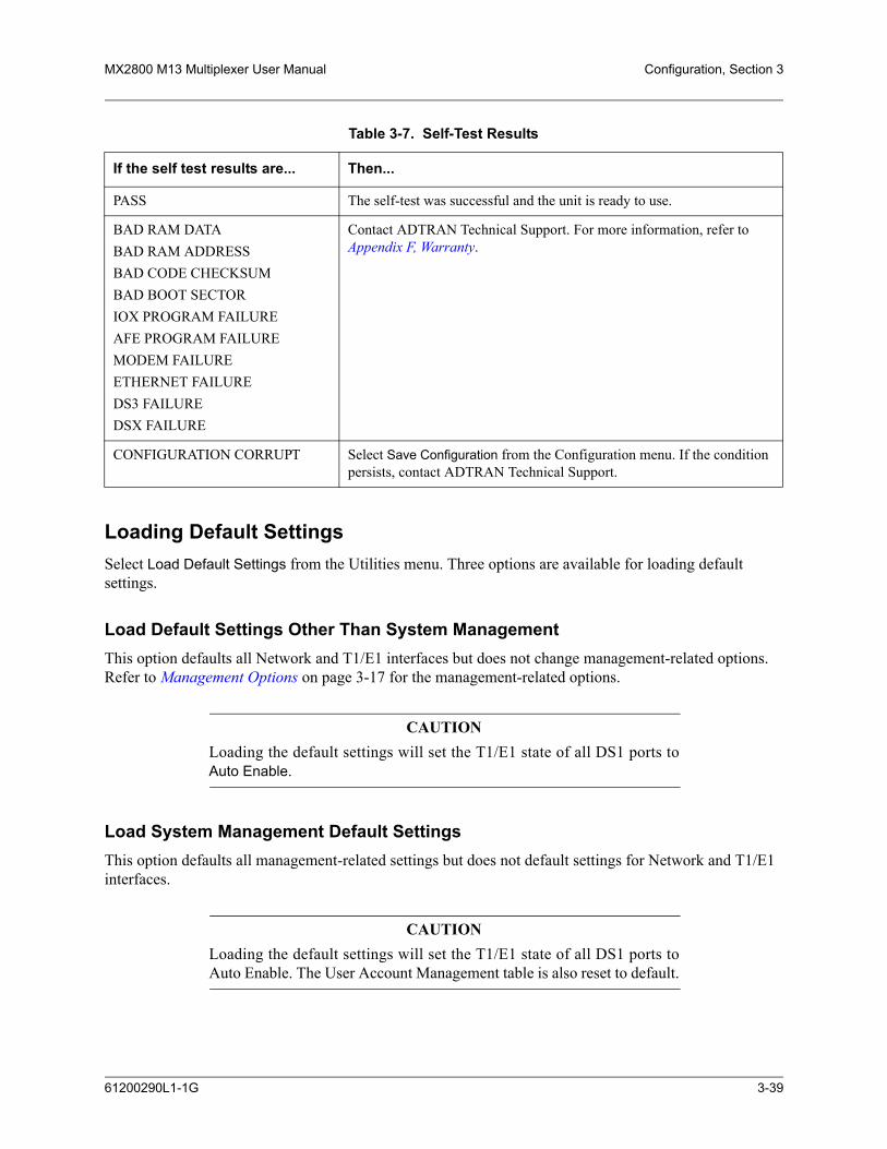
MX2800 M13 Multiplexer User Manual Configuration, Section 3
Loading Default SettingsSelect Load Default Settings from the Utilities menu. Three options are available for loading default settings.
Load Default Settings Other Than System ManagementThis option defaults all Network and T1/E1 interfaces but does not change management-related options. Refer to Management Options on page 3-17 for the management-related options.
CAUTIONLoading the default settings will set the T1/E1 state of all DS1 ports toAuto Enable.
Load System Management Default SettingsThis option defaults all management-related settings but does not default settings for Network and T1/E1 interfaces.
CAUTIONLoading the default settings will set the T1/E1 state of all DS1 ports toAuto Enable. The User Account Management table is also reset to default.
Table 3-7. Self-Test Results
If the self test results are... Then...
PASS The self-test was successful and the unit is ready to use.
BAD RAM DATABAD RAM ADDRESSBAD CODE CHECKSUMBAD BOOT SECTORIOX PROGRAM FAILUREAFE PROGRAM FAILUREMODEM FAILUREETHERNET FAILUREDS3 FAILUREDSX FAILURE
Contact ADTRAN Technical Support. For more information, refer to Appendix F, Warranty.
CONFIGURATION CORRUPT Select Save Configuration from the Configuration menu. If the condition persists, contact ADTRAN Technical Support.
61200290L1-1G 3-39

Section 3, Configuration MX2800 M13 Multiplexer User Manual
Load All Default SettingsThis option defaults all settings for the unit. Once the settings have been successfully retrieved, Command Accepted will appear at the bottom of the screen
CAUTIONThe User Account Management table is also reset to default.
Updating SoftwareSelect Update Flash Software from the Utilities menu to update software, using either XModem protocol or TFTP.
NOTEBefore beginning update of Flash software, disable the Auto Save featureof the MX2800. From the Configuration menu, choose SystemManagement, then select Auto Save and toggle until it is set to Disable.
Update Via XModemUpdating the Flash Software via XModem requires that a VT100 terminal menu session be active through the units craft port. To update the software via XModem, follow these steps:
1. From the MX2800 Main Menu, select Configuration, then Utilities, then Update Flash Software, and then Update via XModem.
2. Once it has been determined where the new binary file is located, select Start to begin the transfer.
3. Once Start has been selected, start the XModem transfer from the terminal menu program that is being used by selecting or typing the file path for the location of the new binary file. Refer to the appropriate documentation for the terminal emulator to begin XModem transfer.
4. After the binary file has been selected, the XModem transfer will begin. To cancel a transfer in progress, press CTRL+X three times. The ACT LED on the active card is solid amber for the duration of XModem transfer. The ACT LED on the standby card is flashing green.
5. If updating a unit with redundant controller cards, the active controller will begin uploading the new code to the standby controller after the XModem transfer has completed and the unit has successfully loaded and programmed the new software into its Flash memory. If the unit does not have redundant controller cards, go to Step 7.
6. While the standby card is having code uploaded, the ACT LED on the standby card will be solid amber. After the code has finished uploading to the standby card, the card will reset itself and begin running the new code.
3-40 61200290L1-1G

MX2800 M13 Multiplexer User Manual Configuration, Section 3
CAUTIONThe standby card must remain in place until the upload process iscomplete and the ACT LED is no longer solid amber and returns toflashing green. Removing the standby card during the uploading processwill corrupt the software.
7. The system must be manually reset after downloading new software for the active controller card to begin running the new code. From the Utilities menu, select System Reset, then select either Immediate Reset to immediately reset the system or Schedule Reset Time to set a time for the system to reset. Once the system has been reset, the new software will be running.
NOTEThis function is available only when updating the software through thecraft port.
Update Via TFTP ServerUpdating the FLASH Software via TFTP Server requires that the IP address and file name of file to be downloaded be known. To update the software via TFTP, follow the steps below:
1. Select Update via TFTP Server from the Utilities menu. A new menu displays, allowing the IP address and file name of the file to be downloaded to the unit to be entered. Once this information is entered, select Start/Stop Transfer.
2. After the binary file is selected, the TFTP transfer will begin. To cancel a transfer in progress, press CTRL+X three times. The ACT LED on the active card is solid amber for the duration of TFTP transfer. The ACT LED on the standby card is blinking green.
3. If updating a unit with redundant controller cards, the active controller begins uploading the new code to the standby controller after the XModem transfer has completed; and the unit has successfully loaded and programmed the new software into its FLASH memory. If the unit does not have redundant controller cards, go to Step 5.
4. While the standby card is having code uploaded, the ACT LED on the standby card will be solid amber. After the code has finished uploading to the standby card, the card will reset itself and begin running the new code.
CAUTIONThe standby card must remain in place until the upload process iscomplete, and the ACT LED is no longer solid amber. Removing thestandby card during the uploading process will corrupt the software.
5. The system must be manually reset after downloading new software for the active controller card to begin running the new code. From the Utilities menu, select System Reset. Then select either
61200290L1-1G 3-41

Section 3, Configuration MX2800 M13 Multiplexer User Manual
Immediate Reset to immediately reset the system or Schedule Reset Time to set a time for the system to reset. Once the system has been reset, the new software will be running.
NOTEAfter new software has been downloaded to the MX2800 system, acondition known as a “software version mismatch” exists on the activecard. The currently running software version is different from the versionof the new software that was just programmed into the card's nonvolatilememory. This condition occurs because a manual card reset is necessaryfor the card to begin running the new software. If the software versionbeing run by the system before the upgrade began was 2.00 or higher, thismismatch will be indicated by a TL1 standing condition (condition codePROGFLT) and a repeating message displayed at the bottom of all menuscreens. This is not a service-affecting condition; however, it is recom-mended that the download process be completed by resetting the activecard as soon as it is practical. Doing so assures that all improvements inthe new software are fully available.
Configuration TransferSelect Config Transfer from the Utilities menu to transfer files to and from a TFTP server. The Config Transfer option is used to save the MX2800 configuration as a backup file, ensuring that the same configu-ration can be used with multiple MX2800 units. Only one configuration transfer session (upload or download) can be active at a time.
NOTEBefore using Config Transfer, the MX2800 should have a valid IPaddress, subnet mask, and default gateway (if required) and should beconnected to an Ethernet network.
Saving to a TFTP ServerTo save current configuration information to a TFTP server, follow the steps listed below:
1. Set the Server IP Address field to the IP address of the machine running the TFTP server program.
If the ADTRAN TFTP server is being used, the IP address displays in the Server IP Address field. For other TFTP servers, refer to the appropriate documentation.
2. Change the TFTP Server Filename to a unique filename. This will be the name of the configuration file saved to the remote server.
3-42 61200290L1-1G

MX2800 M13 Multiplexer User Manual Configuration, Section 3
NOTESome TFTP servers constrain the format of the filename, depending onthe operating system of the server. For example, a TFTP server runningon a PC under Windows 3.1 may permit only 8.3 format filenames (8characters, period, and three extension characters).
3. Select Save Config Remotely.
Retrieving from a TFTP ServerTo retrieve current configuration information from a TFTP server, follow the steps listed below:
1. Set the Server IP Address field to the IP address of the machine running the TFTP server program.
If the ADTRAN TFTP server is being used, the IP address displays in the Server IP Address field. For other TFTP servers, please refer to the appropriate documentation.
2. Change the TFTP Server File Name to a unique filename, including the complete path. This will be the name of the configuration file retrieved from the remote server.
CAUTIONConfiguration changes will not be implemented until all Telnet sessionsare closed. Loading a new configuration may disrupt data traffic.
3. Select Load and Use Config.
NOTEIP address and management port settings remain unchanged when aconfigurative is retrieved from a TFTP server.
Resetting the SystemThe system must be manually reset after downloading new software. When the unit has successfully loaded and programmed the new software into its FLASH memory, it will begin uploading the code to the standby controller. This will be indicated on the menu and the ACT LED on the standby card will display solid yellow.
CAUTIONThe standby card must remain in place until the process is complete andthe ACT LED is no longer solid yellow. Removing the standby cardduring the uploading process will corrupt the software.
61200290L1-1G 3-43

Section 3, Configuration MX2800 M13 Multiplexer User Manual
Once the upload is complete, the standby card will self-reset and begin running the new code. However, the active card does not reset automatically. The unit must be reset through the Immediate Reset or Sched-ule Reset Time functions.
6. SAVE CONFIGURATION AND ALARM LOGCommits the current configuration and alarm log to nonvolatile memory. If this option is not selected after making changes to the configuration, the unit reverts to its previous configuration when powered down. When the selection is made, a response is displayed on the Save Configuration and Alarm menu. See Figure 3-18 on page 3-44.
Figure 3-18. Indication of a Saved Configuration and Alarm Log
3-44 61200290L1-1G

SECTION 4, STATUS
Section 4Status
1. INTRODUCTIONView MX2800 status information by selecting Status from the Main Menu. The information for the DS3, DS2s, T1/E1 lines, power supplies, and controller cards is provided. See Figure 4-1.
Figure 4-1. Status Menu
2. DS3 STATEThis field displays the current state of the DS3. The following subsections describe the DS3 status fields in detail.
Rx FramingThis field shows the network framing type (C-Bit or M13).
61200290L1-1G 4-1

Section 4, Status MX2800 M13 Multiplexer User Manual
StateThis field displays the current condition of the network. Possible conditions are listed in Table 4-1.
AlarmThis field displays the current alarm condition of the MX2800. Possible conditions are given in Table 4-2.
Table 4-1. Network State Conditions
Condition Description
Normal The MX2800 is ready to pass data.
Alarm The unit is currently receiving an alarm indication. For alarm types, refer to the Alarm subsection.
In Test The unit is currently in test mode. Refer to Section 6, Loopbacks for information on the test type.
Table 4-2. Alarm Conditions
Condition Description
Normal No alarms are currently being received.
RAI The unit is receiving an RAI (yellow) alarm from the network. This alarm is a sig-nal sent back toward the source of a failed transmit circuit. The X-bits (X1 and X2) are set to zero.
LOS The unit has lost the Rx signal.
AIS The unit is receiving an AIS (blue) alarm condition from the network. AIS alarms occur when consecutive 1010s are received in the information bits, indicating that there is a transmission fault located either at or upstream from the transmitting ter-minal.
LOF The unit detects a framing loss from the network.
XCV The unit is receiving excessive code violations from the network, exceeding the threshold set by the user. For more information, refer to XCV Threshold on page 3-15.
TLOS The transmitter has failed.
Idle The unit detects an idle sequence from the network.
4-2 61200290L1-1G

MX2800 M13 Multiplexer User Manual Status, Section 4
RemoteThis field indicates the current state of the remote MX2800 (available with C-Bit framing only). Possible conditions are given in Table 4-3.
Table 4-3. Remote Alarm Conditions
Condition Description
Normal The far-end MX2800 is not reporting any alarm conditions.
RAI The far-end unit is receiving an RAI (yellow) alarm from the network. This alarm is a signal sent back toward the source of a failed transmit circuit. The X-bits (X1 and X2) are set to zero.
LOS The far-end unit has lost the Rx signal.
AIS The far-end unit is receiving an AIS (blue) alarm condition from the network. AIS alarms occur when consecutive 1010s are received in the information bits, indicat-ing that there is a transmission fault located either at or upstream from the transmitting terminal.
LOF The far-end unit detects a framing loss from the network.
Idle The far-end unit detects an idle sequence from the network.
DS3 Eqpt Fail (SA) The far-end unit or network is reporting a service-affecting DS3 equipment failure.
DS3 Eqpt Fail (NSA) The far-end unit or network is reporting a non-service-affecting DS3 equipment failure.
Common Eqpt Fail (NSA) The far-end unit or network is reporting a non-service-affecting common equipment failure.
Multiple DS1 LOS The far-end unit is experiencing a loss of signal on multiple DS1s.
Single DS1 LOS The far-end unit is experiencing a loss of signal on a single DS1.
DS1 Eqpt Fail (SA) The far-end unit is experiencing a service-affecting DS1 equipment failure.
DS1 Eqpt Fail (NSA) The far-end unit is experiencing a non-service-affecting DS1 equipment failure.
Unknown The unit is unable to discern the status of the far-end unit. (Normal for M13 framing.)
61200290L1-1G 4-3

Section 4, Status MX2800 M13 Multiplexer User Manual
3. POWER SUPPLY STATEThis field indicates which types of power supplies are installed (AC or DC) in Card A and Card B and gives their current state. See Table 4-4.
4. SYSTEM STATEThese fields display information regarding the two controller cards. The following sections describe the system state fields in detail.
AlarmThis field displays what type (if any) of system alarm is currently recognized by the unit. The condition is displayed until it clears up, with the exception of the Switched condition (which is cleared manually) and the Excessive Switches (which is cleared when Protection Switch alarms counts are cleared). For more information, refer to Protection Switch Statistics on page 5-14.
To clear the Switched condition, select Acknowledge Alarms (ACO) or push the ACO button on the front panel. For more information, refer to ACO Buttons on page 2-15 and Acknowledge Alarms (ACO) on page 4-6 in this section. Possible alarm types are listed in Table 4-5.
Table 4-4. Power Supply Conditions
Condition Description
Normal The power supply is fully operational.
Error The controller card cannot communicate with the power supply.
Power Low The power supply output level is abnormally low.
Power Fail The power supply input power is lost.
Charger Fail The battery backup charger has failed or has lost its AC input.
Battery Low The battery backup has reached an insufficient energy level to power the unit.
Temp High The power supply card temperature is abnormally high.
Temp Critical The power supply card temperature is so high that it is approaching shut off.
Table 4-5. System State Alarm Types
Condition Description
Supply Failure A power supply card has failed.
Card Failure A controller card is not passing data.
Excessive Switches The Max Switching Threshold has been exceeded. Refer to Maximum Switch Threshold on page 3-6.
Switched A card switch has occurred.
4-4 61200290L1-1G

MX2800 M13 Multiplexer User Manual Status, Section 4
Card A/Card BThese fields display the current state of the two controller cards. Possible states for the controller cards are listed in Table 4-6.
ProtectionThis field lists the type of protection mode currently active. Possible states are listed in Table 4-7.
NOTEFor more information on the various types of Protection Modes, refer toSection 7, Circuit and Network Redundancy.
Card CommThis field displays the current state of the communication link between the two controller cards.
• OK indicates that the cards are communicating• Failure indicates that the cards are not able to communicate with each other• If there is only one card installed, Non-Redundant is displayed
Table 4-6. Controller Card States
Condition Description
Not Installed No controller card is installed in this slot.
Standby The controller card is ready to pass data but is currently acting as a backup card.
Active The controller card is acting as the primary card.
Failure The controller card has failed and needs to be replaced.
Table 4-7. Protection Types
Condition Description
Network Both controller cards are installed and everything is healthy. The unit is in full network protection mode.
Circuit Unit is in Circuit Protection Mode and everything is healthy,orunit is in network protection mode and a failure is present on the network.
None One controller card is installed,orthe unit is in Circuit Protection Mode, and the secondary card has failed.
61200290L1-1G 4-5

Section 4, Status MX2800 M13 Multiplexer User Manual
5. DS2 STATEThis field displays the current state of each of the seven DS2s. Possible states are listed in Table 4-8.
6. T1/E1 STATEThis field displays the current state of the individual T1s or E1s. Possible states are listed in Table 4-9.
NOTEA DS2 can be divided into either three E1s or four T1s. Therefore, whendealing with an E1 configuration, some of the fields in the T1/E1 Statemenus do not apply (and display nothing).
7. ACKNOWLEDGE ALARMS (ACO)This selection is used to remotely turn off an active alarm. It is the software equivalent of the ACO button as described in ACO Buttons on page 2-15.
Table 4-8. DS2 States
Condition Description
OK The DS2 is not receiving alarms.
LOF The unit detects framing loss across the DS2.
RAI The unit is receiving an RAI (yellow) alarm across the DS2. This alarm is a signal sent back toward the source of a failed transmit circuit. The X-bit is set to zero.
AIS The unit is receiving an AIS (blue) alarm condition from the network across the DS2. AIS alarms occur when the unit receives unframed all ones.
Table 4-9. T1/E1 States
Condition Description
OK The T1/E1 is ready to pass data.
LOS The unit has lost the Rx signal on the T1/E1.
XCV The unit is receiving excessive code violations across the T1/E1, exceeding the configured threshold (refer to XCV Threshold on page 3-15).
TST The T1/E1 is currently in test mode.
HOT The T1/E1 transceiver temperature is too high.
LAIS The T1 is receiving all ones from the DSX-1 interface.
CAIS The T1 is receiving all ones from the DS3 side of the network.
4-6 61200290L1-1G

SECTION 5, STATISTICS
Section 5Statistics
1. INTRODUCTIONTo access Statistics menu, select Statistics from the Main Menu. See Figure 5-1. Alarm information and performance parameters are available for both the near and far ends of the network. Information is also given for the individual DS2s and T1/E1 lines.
2. VIEWING STATISTICAL INFORMATIONStatistical information is given in screens based on these time periods:
• The current 15-minute interval
• A 24-hour history (divided into 96 15-minute intervals)
• The totals for the previous 24 hours
• A cumulative alarm count is given (this count continues indefinitely until reset by the user)
Figure 5-1. Statistics Menu
61200290L1-1G 5-1

Section 5, Statistics MX2800 M13 Multiplexer User Manual
DS3 StatisticsThe DS3 Statistics menu, see Figure 5-2, provides submenus for alarm history and performance parame-ters.
Figure 5-2. DS3 Statistics Menu
24 Hour Alarm HistoryThe MX2800 keeps track of alarms for both the near and far ends of the network. View alarm history infor-mation in one of the three time period selections, or view a cumulative alarm count. Information in these fields is for the given time period since the last reset. The cumulative alarm count continues indefinitely until Clear All DS3 Alarm Counts is selected. See Table 5-1 for a list of alarm counts. See Figure 5-3 on page 5-3 and Figure 5-4 on page 5-4 for examples of alarm screens.
Table 5-1. Alarm Counts
Condition Description
LOS Number of times the unit has lost the receive signal.
LOF Number of times the unit has detected a loss of framing from the network.
AIS Number of times the unit has received an AIS (blue) alarm condition from the net-work. AIS alarms occur when consecutive 1010s are received in the information bits. This indicates that there is a transmission fault located either at or upstream from the transmitting terminal.
RAI Number of times the unit has received an RAI (yellow) alarm from the network. This alarm is a signal sent back toward the source of a failed transmit circuit. The X-bits (X1 and X2) are set to zero.
5-2 61200290L1-1G

MX2800 M13 Multiplexer User Manual Statistics, Section 5
NOTEThe count given reflects the number of times the alarm or state hasoccurred rather than the number of seconds the alarm was active.
Figure 5-3. DS3 Current 15 Minute Alarm Count Screen
IDLE Number of times the unit has detected an idle sequence from the network.
Table 5-1. Alarm Counts (Continued)
Condition Description
61200290L1-1G 5-3

Section 5, Statistics MX2800 M13 Multiplexer User Manual
Figure 5-4. DS3 24-Hour Alarm History Screen
NOTEWhen a > or < symbol appears in the upper corner of the screen, use theright and left arrow keys on the keyboard to scroll right or left to viewadditional information. See the upper right-hand corner of Figure 5-4.
Performance ParametersView performance parameter information for the network in one of the three time period selections. Infor-mation in these fields is for the given time period since the last reset. When viewing the 24-hour history statistics screen, use the left and right arrow keys to scroll through all 96 15-minute intervals. See Figure 5-5 on page 5-5, Figure 5-6 on page 5-6, and Figure 5-7 on page 5-7 for examples of the performance parameter screens.
Descriptions of the fields in each screen follow.
5-4 61200290L1-1G
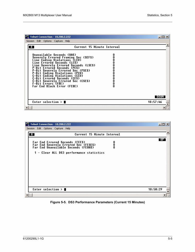
MX2800 M13 Multiplexer User Manual Statistics, Section 5
Figure 5-5. DS3 Performance Parameters (Current 15 Minutes)
61200290L1-1G 5-5

Section 5, Statistics MX2800 M13 Multiplexer User Manual
NOTEWhen an UP or DOWN indicator appears in the corner of the screen, usethe up and down arrow keys on the keyboard to scroll the information.
Figure 5-6. DS3 Performance Parameters (24 Hour History)
5-6 61200290L1-1G
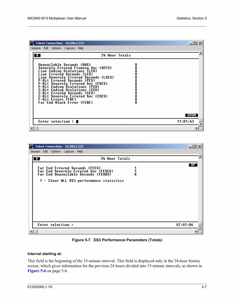
MX2800 M13 Multiplexer User Manual Statistics, Section 5
Figure 5-7. DS3 Performance Parameters (Totals)
Interval starting at:
This field is the beginning of the 15-minute interval. This field is displayed only in the 24-hour history screen, which gives information for the previous 24 hours divided into 15-minute intervals, as shown in Figure 5-6 on page 5-6.
61200290L1-1G 5-7
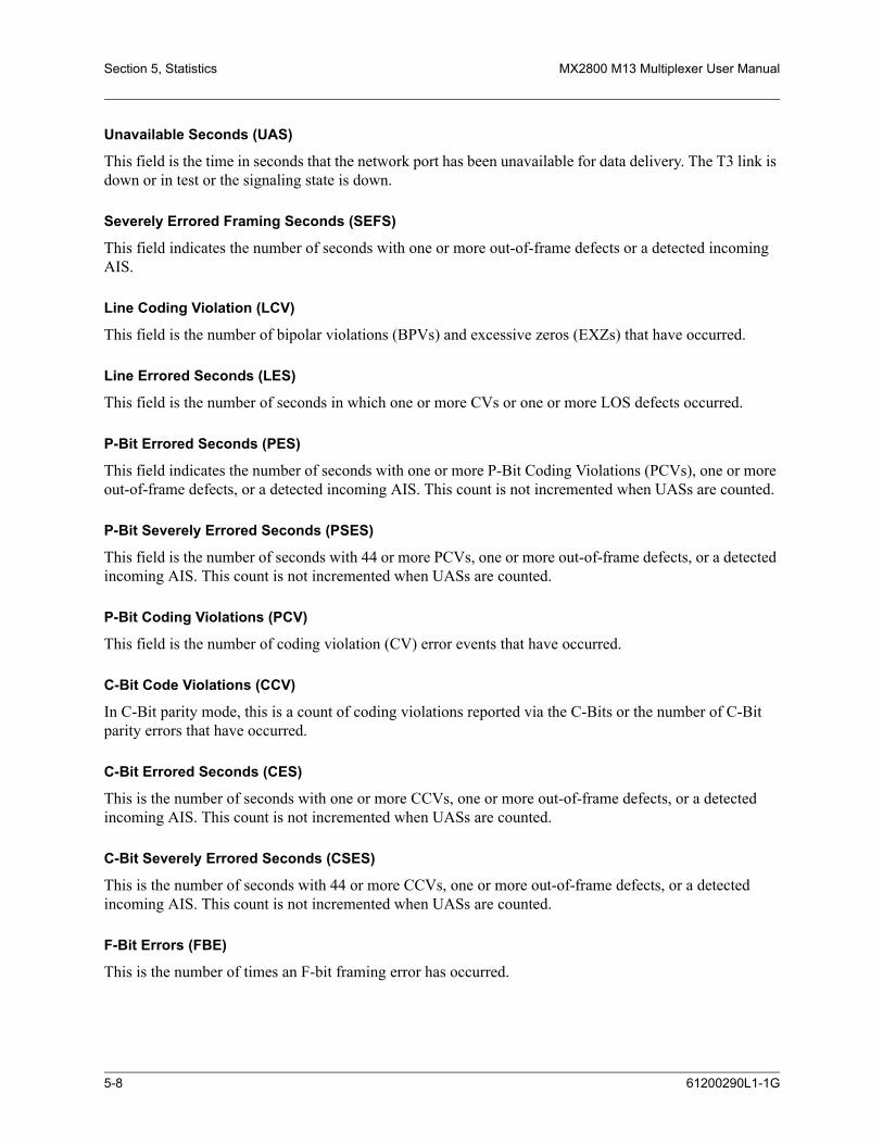
Section 5, Statistics MX2800 M13 Multiplexer User Manual
Unavailable Seconds (UAS)
This field is the time in seconds that the network port has been unavailable for data delivery. The T3 link is down or in test or the signaling state is down.
Severely Errored Framing Seconds (SEFS)
This field indicates the number of seconds with one or more out-of-frame defects or a detected incoming AIS.
Line Coding Violation (LCV)
This field is the number of bipolar violations (BPVs) and excessive zeros (EXZs) that have occurred.
Line Errored Seconds (LES)
This field is the number of seconds in which one or more CVs or one or more LOS defects occurred.
P-Bit Errored Seconds (PES)
This field indicates the number of seconds with one or more P-Bit Coding Violations (PCVs), one or more out-of-frame defects, or a detected incoming AIS. This count is not incremented when UASs are counted.
P-Bit Severely Errored Seconds (PSES)
This field is the number of seconds with 44 or more PCVs, one or more out-of-frame defects, or a detected incoming AIS. This count is not incremented when UASs are counted.
P-Bit Coding Violations (PCV)
This field is the number of coding violation (CV) error events that have occurred.
C-Bit Code Violations (CCV)
In C-Bit parity mode, this is a count of coding violations reported via the C-Bits or the number of C-Bit parity errors that have occurred.
C-Bit Errored Seconds (CES)
This is the number of seconds with one or more CCVs, one or more out-of-frame defects, or a detected incoming AIS. This count is not incremented when UASs are counted.
C-Bit Severely Errored Seconds (CSES)
This is the number of seconds with 44 or more CCVs, one or more out-of-frame defects, or a detected incoming AIS. This count is not incremented when UASs are counted.
F-Bit Errors (FBE)
This is the number of times an F-bit framing error has occurred.
5-8 61200290L1-1G

MX2800 M13 Multiplexer User Manual Statistics, Section 5
Far End Block Error (FEBE)
This field indicates the number of times the far-end unit has received a C-parity or framing error.
Clear All Local DS3 Statistics/Refresh All Remote Statistics
Use this option to clear or refresh all current information. These selections affect all statistical information, not just the displayed screen. When viewing the 24-Hour History screen, press the DOWN arrow key to access this selection.
DS2 Statistics
24-Hour Alarm HistoryThe MX2800 keeps track of RAI, OOF, and AIS alarms for each of the seven DS2s. View alarm history information in one of the three time period selections, or view a cumulative alarm count. Information in these fields is for the given time period since the last reset. The cumulative alarm count continues indefi-nitely until Clear All DS2 Alarm Counts is selected. When viewing the 24-Hour History menus, use the UP and DOWN arrow keys to view all three alarm counts (RAI, OOF, and AIS). See Figure 5-8 and Figure 5-9 on page 5-10.
Figure 5-8. DS2 Current 15 Minute Alarm Count Screen
61200290L1-1G 5-9

Section 5, Statistics MX2800 M13 Multiplexer User Manual
Figure 5-9. DS2 RAI 24-Hour Alarm History
5-10 61200290L1-1G

MX2800 M13 Multiplexer User Manual Statistics, Section 5
Performance ParametersThe performance parameters screen displays a count of parity bit errors and frame bit errors for the seven DS2s. View this information in any of the three time period selections. Information in these fields is for the given time period since the last reset. When viewing the 24-hour history statistics screen, use the LEFT and RIGHT arrow keys to scroll through all 96 15-minute intervals; use the UP and DOWN arrow keys to scroll between the PBERR (parity bit error) and FBERR (frame bit error) menus. See Figure 5-10 and Figure 5-11.
Figure 5-10. DS2 Performance Parameters (Current 15 Minutes)
61200290L1-1G 5-11
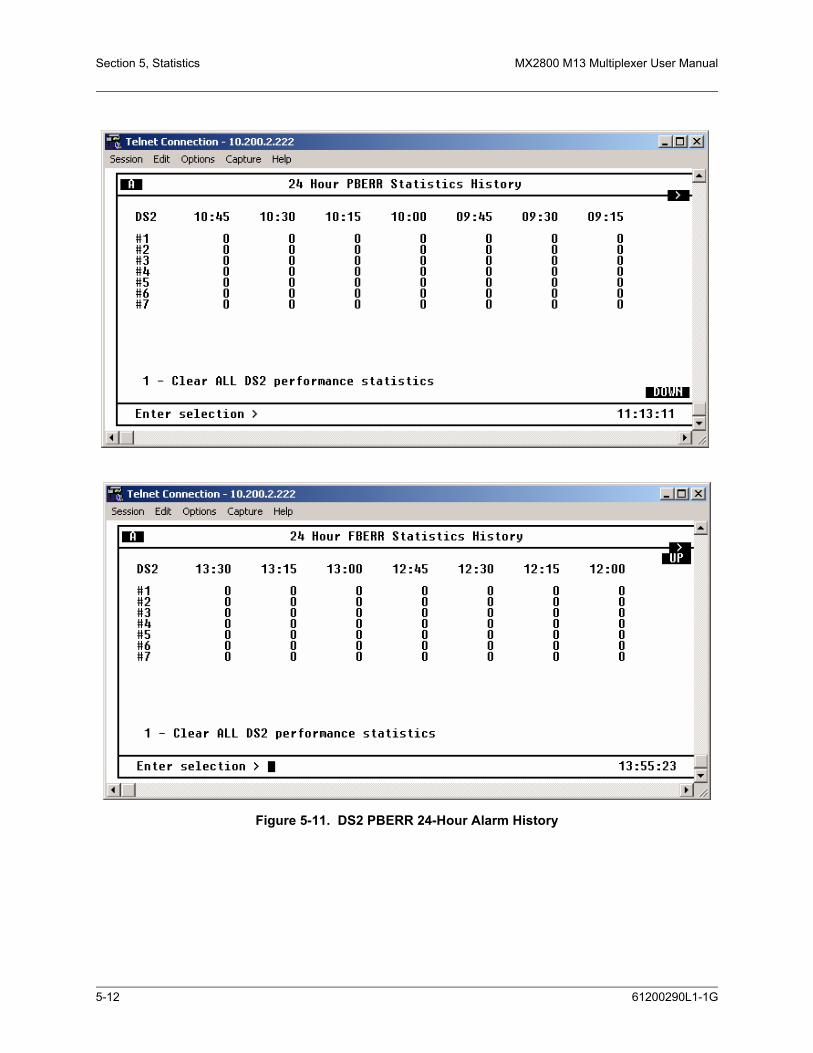
Section 5, Statistics MX2800 M13 Multiplexer User Manual
Figure 5-11. DS2 PBERR 24-Hour Alarm History
5-12 61200290L1-1G

MX2800 M13 Multiplexer User Manual Statistics, Section 5
T1/E1 StatisticsThe MX2800 keeps track of the following statistics for each of the T1s and E1s:
• Loss of Signal Alarms
• Line Coding Violations
• AIS Loop Alarms
• AIS Carrier Alarms
• Errored Seconds
• Severely Errored Seconds
See Figure 5-12. View this information in one of the three time period selections, or view a cumulative alarm count. Information in these fields is for the given time period since the last reset. The cumulative alarm count continues indefinitely until Clear All T1/E1 Alarm Counts, located in each field, is selected.
Performance parameters that are documented for the T1s and E1s are
• Errored Seconds
• Severely Errored Seconds
• Severely Errored Framing Seconds
• Unavailable Seconds
• Degraded Minutes
The current interval, past 24-hours in 15-minute intervals, and 24-hour totals for each of these may be viewed.
Figure 5-12. T1/E1 Port Local Statistics Menu
61200290L1-1G 5-13

Section 5, Statistics MX2800 M13 Multiplexer User Manual
3. PROTECTION SWITCH STATISTICSThis menu provides statistics regarding protection switches. The number of protection switches that occur within the particular time period are listed. See Figure 5-13 on page 5-14.
Figure 5-13. Protection Switch Statistics Menu
Performance ParametersView performance parameter information for the network in one of the three time period selections. Infor-mation in these fields is for the given time period since the last reset. When viewing the 24-Hour History statistics screen, use the LEFT and RIGHT arrow keys to scroll through all 96 15-minute intervals. Clearing protection switch alarm counts will clear the Excessive Switch State, if active.
Alarm LogThis menu provides a list of the last 200 alarms that have occurred on the MX2800. When the alarm log becomes full, new alarms replace the oldest alarms in a first-in, first-out sequence.
The alarm log is periodically stored in nonvolatile memory. Once every minute, if an alarm has been recorded or if the alarm log has been reset since the last time it was saved, then the alarm log and system configuration are saved to nonvolatile memory. Both the alarm log and system configuration are saved manually when the user executes the Save Configuration & Alarm Log menu function in the Configuration menu. Each time the system powers up, the alarm log is retrieved from non-volatile memory.
A Reset Alarm Log function is accessible from the alarm log menu. This option clears the alarm log. See Figure 5-14 on page 5-15.
5-14 61200290L1-1G

MX2800 M13 Multiplexer User Manual Statistics, Section 5
Figure 5-14. Alarm Log
61200290L1-1G 5-15

Section 5, Statistics MX2800 M13 Multiplexer User Manual
This page is intentionally blank.
5-16 61200290L1-1G

SECTION 6, LOOPBACKS
Section 6Loopbacks
1. INTRODUCTIONThe Loopback menu initiates loopback tests from the MX2800. Figure 6-1 shows the main Loopback menu. To initiate a loopback, select Loopback Menu.
To locate descriptions of the types of loopback tests that are available, find T1/E1, DS2, or DS3 Loopback descriptions. Next, select by number the type of loopback for a description.
Descriptions and testing diagrams of the loopback tests are provided in the following subsections:
• T1/E1 Loopbacks on page 6-2
• DS3 Loopbacks on page 6-6
• DS2 Loopbacks on page 6-9
Figure 6-1. Loopback Menu
61200290L1-1G 6-1

Section 6, Loopbacks MX2800 M13 Multiplexer User Manual
2. T1/E1 LOOPBACKSSelecting Data Mode Menu from the Loopback menu brings up the control menu shown in Figure 6-1. If initiating a T1/E1 loopback, select the facility number (1-28). A loopback menu for the facility displays a menu of nine types of loopbacks. See Figure 6-2. Select Data Mode to end a loopback test in progress.
Figure 6-2. Loopback Control Menu
Data ModeSelecting the Data Mode from the Loopback Control menu ends any loopback test in progress.
TributaryA Tributary loopback loops the selected T1/E1 back to the network (DS3). The T1/E1 is demultiplexed through the M23 and M12/G.747 demultiplexers, looped back, and multiplexed back up through the M12/G.747 and M23 multiplexers. During this loopback, all network receive data is passed to the DSX-1/E1 transmitters, but all data received by the DSX-1/E1 loop side is ignored and substituted with the network data. See Figure 6-3 for an illustration of this test.
6-2 61200290L1-1G
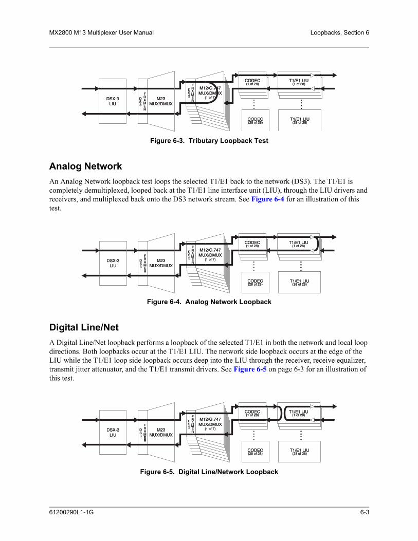
MX2800 M13 Multiplexer User Manual Loopbacks, Section 6
Figure 6-3. Tributary Loopback Test
Analog NetworkAn Analog Network loopback test loops the selected T1/E1 back to the network (DS3). The T1/E1 is completely demultiplexed, looped back at the T1/E1 line interface unit (LIU), through the LIU drivers and receivers, and multiplexed back onto the DS3 network stream. See Figure 6-4 for an illustration of this test.
Figure 6-4. Analog Network Loopback
Digital Line/NetA Digital Line/Net loopback performs a loopback of the selected T1/E1 in both the network and local loop directions. Both loopbacks occur at the T1/E1 LIU. The network side loopback occurs at the edge of the LIU while the T1/E1 loop side loopback occurs deep into the LIU through the receiver, receive equalizer, transmit jitter attenuator, and the T1/E1 transmit drivers. See Figure 6-5 on page 6-3 for an illustration of this test.
Figure 6-5. Digital Line/Network Loopback
DSX-3LIU
M23MUX/DMUX
M12/G.747MUX/DMUX
(1 of 7)
FRAMER
DS2
FRAMER
DS3 ..
..
....
T1/E1 LIU(1 of 28)
CODEC(28 of 28)
CODEC(1 of 28)
T1/E1 LIU(28 of 28)
DSX-3LIU
M23MUX/DMUX
M12/G.747MUX/DMUX
(1 of 7)
FRAMER
DS2
FRAMER
DS3 ..
..
T1/E1 LIU(1 of 28)
CODEC(28 of 28)
CODEC(1 of 28)
T1/E1 LIU(28 of 28)
DSX-3LIU
M23MUX/DMUX
M12/G.747MUX/DMUX
(1 of 7)
FRAMER
DS2
FRAMER
DS3 ..
..
....
T1/E1 LIU(1 of 28)
CODEC(28 of 28)
CODEC(1 of 28)
T1/E1 LIU(28 of 28)
DSX-3LIU
M23MUX/DMUX
M12/G.747MUX/DMUX
(1 of 7)
FRAMER
DS2
FRAMER
DS3 ..
..
T1/E1 LIU(1 of 28)
CODEC(28 of 28)
CODEC(1 of 28)
T1/E1 LIU(28 of 28)
DSX-3LIU
M23MUX/DMUX
M12/G.747MUX/DMUX
(1 of 7)
FRAMER
DS2
FRAMER
DS3 ..
..
....
T1/E1 LIU(1 of 28)
CODEC(28 of 28)
CODEC(1 of 28)
T1/E1 LIU(28 of 28)
DSX-3LIU
M23MUX/DMUX
M12/G.747MUX/DMUX
(1 of 7)
FRAMER
DS2
FRAMER
DS3 ..
..
T1/E1 LIU(1 of 28)
CODEC(28 of 28)
CODEC(1 of 28)
T1/E1 LIU(28 of 28)
61200290L1-1G 6-3

Section 6, Loopbacks MX2800 M13 Multiplexer User Manual
Codec Line/NetA Codec Line/Net loopback performs a loopback of the selected T1/E1 in both the network and local loop directions. Both loopbacks occur at the T1/E1 codec. Both the network and the local loop side of the loopback are executed at the edge of the codec, completely testing the M13 mux and the T1/E1 LIU. See Figure 6-6 on page 6-4 for an illustration of this test.
Figure 6-6. Codec Loopback
Remote LoopbackA Remote Loopback performs a loopback of the selected T1/E1 on the far-end M13 multiplexer. If an MX2800 is located at the far end, an Analog Network Loopback is executed when a Remote Loopback is engaged. This loopback is only available when the DS3 is configured for C-bit parity framing since it requires the availability of the far-end alarm and control (FEAC) channel. See ANSI T1.107.
CSU LoopbackA CSU Loopback enables the MX2800 to generate a CSU loop up pattern (001001…) toward the T1 CSU attached to the selected T1 line for six seconds. After six seconds have elapsed, the pattern ceases; and incoming network traffic is passed through to the CSU device. If the CSU device responded to the CSU loop up pattern, it returns all data back toward the network. A loop down pattern (0000100001….) is generated toward the CSU for 6 seconds when Data Mode is selected.
NOTEWhen in CSU Loopback, only the Data Mode for the T1 under test may beselected. Selecting any other option will result in an error message.
CSU Loopback w/BERTA CSU Loopback w/BERT enables the MX2800 to test the local T1 loop to the CSU using the QRSS pseudorandom bit sequence. When CSU Loopback w/BERT is selected, the MX2800 initiates a CSU loopback toward the CSU attached to the selected T1 line. Six seconds after starting the CSU loop up pattern, the MX2800 ceases sending the CSU loop up pattern and begins sending an unframed QRSS pattern toward the CSU. If the CSU device responded to the CSU loop up pattern, the MX2800 checks the incoming pattern for errors. Additional menu items appear to show the state of pattern synchronization,
DSX-3LIU
M23MUX/DMUX
M12/G.747MUX/DMUX
(1 of 7)
FRAMER
DS2
FRAMER
DS3 ..
..
....
T1/E1 LIU(1 of 28)
CODEC(28 of 28)
CODEC(1 of 28)
T1/E1 LIU(28 of 28)
DSX-3LIU
M23MUX/DMUX
M12/G.747MUX/DMUX
(1 of 7)
FRAMER
DS2
FRAMER
DS3 ..
..
T1/E1 LIU(1 of 28)
CODEC(28 of 28)
CODEC(1 of 28)
T1/E1 LIU(28 of 28)
6-4 61200290L1-1G

MX2800 M13 Multiplexer User Manual Loopbacks, Section 6
error count, and a clear error count option. See Figure 6-7 on page 6-5. Selecting Data Mode will cease the transmission of the QRSS pattern and start transmission of a loop down pattern as previously described.
NOTEWhen in CSU Loopback w/BERT, only the Data Mode for the T1 undertest may be selected. Selecting any other option results in an errormessage.
Figure 6-7. Loopback Menu with BERT Selected
Line BERTA Line BERT enables the MX2800 to perform a “head-to-head” BERT test toward the CSU. Selecting Line BERT replaces all incoming network traffic for the selected T1 with an unframed QRSS pattern toward the CSU. When Line BERT is selected, additional menu items appear and show the state of pattern synchroni-zation, cumulative error count, and a clear error count option. Selecting Data Mode ceases QRSS pattern generation and substitution of the incoming data stream.
NOTEWhen in Line BERT mode, only the Data Mode option for the T1 undertest may be selected. Selecting any other option will result in an errormessage being displayed.
61200290L1-1G 6-5

Section 6, Loopbacks MX2800 M13 Multiplexer User Manual
NOTEOnly one T1 port may engage a CSU Loopback, CSU Loopback w/BERT,or a Line BERT. If a CSU Loopback, CSU Loopback w/BERT, or a LineBERT is already active at the time a new CSU Loopback, CSU Loopbackw/BERT, or Line BERT is selected, the former test is terminated, and thelatter test is engaged.
3. DS3 LOOPBACKSAfter DS3 Loopback is selected, the menu in Figure 6-8 appears. The sections following the figure provide descriptions and illustrations of the testing options. Select Data Mode to end a test in progress.
Figure 6-8. DS3 Loopback Menu
CAUTIONIf IP forwarding is enabled, a user should not perform a DS3 Loopbackfrom the menus of the far-end (non-LAN end) MX2800. The communi-cation link is over the DS3. If a loopback is performed, communicationwill be lost with the far-end MX2800. If this happens and a loopbacktimeout is not active, the user must cycle power to the far-end MX2800 tocancel the loopback and regain access to the shelf.
6-6 61200290L1-1G

MX2800 M13 Multiplexer User Manual Loopbacks, Section 6
Line LoopbackLine Loopback performs a loop of the DS3 back to the network. This loopback occurs just prior to the DS3 framer and B3ZS decoder, but it makes full use of the DS3 LIU in both receive and transmit directions; therefore, any coding violations received by the DS3 will be inserted back into the network without modification. See Figure 6-9 on page 6-7 for an illustration of this test.
NOTEIf a Line loopback is active when the MX2800 is operating in the Localtiming mode, the timing source for the DS3 is effectively removed fromthe circuit. Therefore, it is up to the test equipment or network to provideDS3 timing into the circuit for the duration of the test.
Figure 6-9. Line Loopback Test
Digital LoopbackA Digital Loopback loops the entire DS3 back to the local loop side. The end effect of this test is a loopback of all T1/E1s after being fully multiplexed and de-multiplexed to and from a DS3. The incoming DS3 data is ignored, and the outgoing DS3 stream is substituted in its place just prior to exiting the DS3 framer. This test is illustrated in Figure 6-10.
Figure 6-10. Digital Loopback
DSX-3LIU
M23MUX/DMUX
M12/G.747MUX/DMUX
(1 of 7)
FRAMER
DS2
FRAMER
DS3 ..
..
....
T1/E1 LIU(1 of 28)
CODEC(28 of 28)
CODEC(1 of 28)
T1/E1 LIU(28 of 28)
DSX-3LIU
M23MUX/DMUX
M12/G.747MUX/DMUX
(1 of 7)
FRAMER
DS2
FRAMER
DS3 ..
..
T1/E1 LIU(1 of 28)
CODEC(28 of 28)
CODEC(1 of 28)
T1/E1 LIU(28 of 28)
DSX-3LIU
M23MUX/DMUX
M12/G.747MUX/DMUX
(1 of 7)
FRAMER
DS2
FRAMER
DS3 ..
..
....
T1/E1 LIU(1 of 28)
CODEC(28 of 28)
CODEC(1 of 28)
T1/E1 LIU(28 of 28)
DSX-3LIU
M23MUX/DMUX
M12/G.747MUX/DMUX
(1 of 7)
FRAMER
DS2
FRAMER
DS3 ..
..
T1/E1 LIU(1 of 28)
CODEC(28 of 28)
CODEC(1 of 28)
T1/E1 LIU(28 of 28)
61200290L1-1G 6-7

Section 6, Loopbacks MX2800 M13 Multiplexer User Manual
Metallic LoopbackA Metallic Loopback test loops the entire DS3 back to the local loop side. The end effect of this test is a loopback of all T1/E1s after being fully multiplexed and de-multiplexed to and from a DS3 and passed through both directions of the DS3 LIU. During this test, the incoming DS3 is disconnected from the DS3 receiver and the outgoing DS3 signal is substituted in its place. See Figure 6-11 on page 6-8 for an illustra-tion of this test.
NOTEThe DS3 Line Length should be set to Short before performing thisloopback.
Figure 6-11. Metallic Loopback Test
Remote LoopbackA Remote Loopback performs a loopback on the far-end M13 multiplexer. This loopback is available only when the DS3 is configured for C-bit parity framing since it requires the availability of the FEAC channel. See ANSI T1.107.
NOTELocal timing must be selected before initiating this loopback. Ifnecessary, it may be returned after loopback has been cancelled.
Remote All T1/E1A Remote All T1/E1 loopback performs a loopback of all T1/E1 channels on the far-end M13 multiplexer. If an MX2800 is located at the far end, an Analog Loopback is executed on all active channels simulta-neously. The form of this loopback code sent to the far-end will depend on the framing mode being used. When in C-Bit parity mode, the MX2800 will send loopback commands over the FEAC channel. When operating in M13 framing mode, the MX2800 will send C-Bit loopbacks at the DS2 level.
DSX-3LIU
M23MUX/DMUX
M12/G.747MUX/DMUX
(1 of 7)
FRAMER
DS2
FRAMER
DS3 ..
..
....
T1/E1 LIU(1 of 28)
CODEC(28 of 28)
CODEC(1 of 28)
T1/E1 LIU(28 of 28)
DSX-3LIU
M23MUX/DMUX
M12/G.747MUX/DMUX
(1 of 7)
FRAMER
DS2
FRAMER
DS3 ..
..
T1/E1 LIU(1 of 28)
CODEC(28 of 28)
CODEC(1 of 28)
T1/E1 LIU(28 of 28)
6-8 61200290L1-1G

MX2800 M13 Multiplexer User Manual Loopbacks, Section 6
4. DS2 LOOPBACKSOnce a number has been selected which corresponds with the DS2 to be tested, the DS2 menu in Figure 6-12 on page 6-9 appears. The subsection following the figure provides a description and an illustration of the DS2 Network loopback testing option. Select the appropriate DS2 Data Mode to end a test in progress.
Figure 6-12. DS2 Loopback Menu
DS2 NetworkA DS2 Network loopback test loops the selected DS2 back to the network (DS3) prior to being passed through the M12/G.747 de-multiplexer. All T1/E1s attached to that DS2 will receive data normally, but all data inserted into the T1/E1s attached to the selected DS2 will be ignored and replaced by the incoming DS2 network data. This test is illustrated in Figure 6-13.
Figure 6-13. DS2 Network Loopback Test
DSX-3LIU
M23MUX/DMUX
M12/G.747MUX/DMUX
(1 of 7)
FRAMER
DS2
FRAMER
DS3 ..
..
....
T1/E1 LIU(1 of 28)
CODEC(28 of 28)
CODEC(1 of 28)
T1/E1 LIU(28 of 28)
DSX-3LIU
M23MUX/DMUX
M12/G.747MUX/DMUX
(1 of 7)
FRAMER
DS2
FRAMER
DS3 ..
..
T1/E1 LIU(1 of 28)
CODEC(28 of 28)
CODEC(1 of 28)
T1/E1 LIU(28 of 28)
61200290L1-1G 6-9

Section 6, Loopbacks MX2800 M13 Multiplexer User Manual
This page is intentionally blank.
6-10 61200290L1-1G

SECTION 7, CIRCUIT AND NETWORK REDUNDANCY
Section 7Circuit and Network Redundancy
1. INTRODUCTIONThe MX2800 provides backup measures of protection for circuit failure. The following subsections describe the possible modes of operation:
• Nonredundant Mode on page 7-1 offers no backup protection
• Circuit Failure Recovery Mode on page 7-2 furnishes backup protection in the event of controller card failure
• Circuit and Network Failure Recovery Mode on page 7-3 provides the most complete mode of circuit and network protection.
The descriptions given include illustrations and suggested configuration settings.
NOTEThe settings may need modification based on your network configuration.
2. NONREDUNDANT MODEIn Nonredundant Mode, the MX2800 houses only one controller card. There is no failure protection. In the event of a failure, an alarm is initiated and the front panel LEDs reflect the condition. See Figure 7-1 on page 7-1 for an illustration.
Figure 7-1. Nonredundant Mode
61200290L1-1G 7-1

Section 7, Circuit and Network Redundancy MX2800 M13 Multiplexer User Manual
NOTEIn this mode, the DS3 must be connected to the IN and OUT jacks forDS3 A.
3. CIRCUIT FAILURE RECOVERY MODEIn Circuit Failure Recovery Mode, two controller cards are installed with an incoming single DS3 line. See Figure 7-2 on page 7-2. In this mode, the MX2800 can continue operating in the event of a controller card failure. When both cards are healthy, the primary card actively processes data while the secondary card stands by and is ready to take over if the first fails. The secondary card continuously monitors the line and remains framed to the incoming signal.
NOTEDuring a card switch, service interruption occurs on both the DS3 and theDSX1 connections. However, since the secondary controller card remainsframed to the incoming signal at all times, it is a minimal interruption.
Figure 7-2. Circuit Failure Recovery Mode
See Table 7-1 for a list of this mode’s configuration requirements.
Table 7-1. Configuration Requirements for Circuit Recovery
Selection Path Recommended Setting
Config > Network Interface > XCV Threshold 1E-3 *
Config > Network Interface > Network Protection Disabled
Config > Network Interface > Max. Switch Threshold 3
7-2 61200290L1-1G

MX2800 M13 Multiplexer User Manual Circuit and Network Redundancy, Section 7
*. This is a critical alarm only when Inactive Card is not installed or is not working.
4. CIRCUIT AND NETWORK FAILURE RECOVERY MODEIn this mode, two controller cards are installed and connected to two individual DS3 lines. This is the most complete mode of redundancy. In this mode, the primary controller card is connected to the primary DS3 line and the secondary controller card is connected to the secondary DS3 line. The primary card and line actively transmit data, while the other card and line stand by ready to take over if the first card and line fail.
A feature of the MX2800 is its ability to internally re-route the network connection if a controller card and the opposite network connection fail. For example, in the illustration given in Figure 7-3 on page 7-3, failed DS3 A is connected to healthy Card A and healthy DS3 B is connected to failed Card B. In a case like this, the MX2800 is able to automatically re-route DS3 B to Card A.
The configuration requirements for this mode are the same as the ones given for Circuit Failure Recovery Mode on page 7-2 except for the Network Protection setting, which must be set to Enable.
Figure 7-3. Circuit and Network Failure Recovery Mode
Config > Network Interface > Min. Switching Period 10 seconds
Config > T1/E1 Interface > T1/E1 Circuit Protection Enable all or select theT1/E1s that redundant switching should occur on.
Config > T1/E1 Interface > XCV Threshold 1E-3
Table 7-1. Configuration Requirements for Circuit Recovery (Continued)
61200290L1-1G 7-3

Section 7, Circuit and Network Redundancy MX2800 M13 Multiplexer User Manual
This page is intentionally blank.
7-4 61200290L1-1G

SECTION 8, POWER LOSS RECOVERY
Section 8Power Loss Recovery
1. INTRODUCTIONThe MX2800 provides backup measures of protection for both power supply and power source failure. The following subsections describe the possible modes of operation:
• Nonredundant Power Mode on page 8-1 offers no backup protection
• Power Supply Recovery Mode on page 8-2 furnishes backup protection in the event of power supply card failure
• Power Supply and Source Recovery Mode on page 8-2 provides a backup system for both card and source failure
• Battery Backup Mode on page 8-3 offers battery backup in the event of a power outage
2. NONREDUNDANT POWER MODEIn Nonredundant Power Mode, the MX2800 houses only one power supply card; and only one power source is available. There is no power failure protection. If a power supply card fails, the unit is down until the card is repaired or replaced. See Figure 8-1 for an illustration.
Figure 8-1. Nonredundant Power Mode
MX2800
61200290L1-1G 8-1

Section 8, Power Loss Recovery MX2800 M13 Multiplexer User Manual
NOTEPower supplies are hot-swappable.
3. POWER SUPPLY RECOVERY MODEIn Power Supply Recovery Mode, two power supply cards are installed and connected to a single power source. See Figure 8-2. In this mode, the MX2800 continues operation in the event of a power supply failure without interrupting service. The power supplies are load sharing, so either power supply can provide power for the entire unit.
NOTEWhen the unit is configured with dual internal AC power supplies, this isthe only power supply protection mode available.
Figure 8-2. Power Supply Failure Recovery Mode
4. POWER SUPPLY AND SOURCE RECOVERY MODEIn this mode, two power supply cards are installed and are connected to two individual power sources. The MX2800 handles any combination of power source or power supply failure.
Much like the backup design for the controller cards, the MX2800 is able to internally re-route the power source if a power supply card and the opposite power source fail. For example, in Figure 8-3 on page 8-3, failed Power Source A is connected to healthy Card A, and healthy Power Source B is connected to failed Card B. In a case like this, the MX2800 automatically connects Power Source B to Card A.
NOTEThis configuration is available only with DC power supplies.
MX2800
8-2 61200290L1-1G

MX2800 M13 Multiplexer User Manual Power Loss Recovery, Section 8
Figure 8-3. Power Supply and Source Failure Recovery Mode
5. BATTERY BACKUP MODEWith the installation of the ADTRAN Power Supply/Battery Charger (PS/BC) and backup battery pack, the MX2800 can continue operation without service interruption in the event of a power outage. This PS/BC (P/N 4175043L2) provides –48 VDC to the MX2800. It receives 115 VAC through a standard plug and wall socket.
The PS/BC maintains the battery at peak charge (–48 VDC) at all times. If AC power is lost, the unit automatically supplies power from the battery without interrupting service. When AC power returns, the unit switches back to AC power and recharges the battery. For installation instructions, refer to the guide provided with the PS/BC. See Figure 8-4 on page 8-4 for an illustration of this setup.
NOTEThe MX2800 can operate on a fully charged battery for 4 hours withoutrecharging.
61200290L1-1G 8-3

Section 8, Power Loss Recovery MX2800 M13 Multiplexer User Manual
Figure 8-4. Battery Backup System
Wh
ite
Gre
en
Bla
ckR
ed
- RETPWRFAIL
- RETPWRFAIL
MX2800
Battery ChargerPower Cable
Magnified View
-48 VDCBackup Battery Pack
P/N 1175044L1
AC Power Input
AC/DC Power SupplyBattery Charging Unit
P/N 1175043Lx
DC POWER 115 AC 50/60Hz0.8A
PWRFAIL RET
T R S T RCLKA
CLKB
S
–
LAN
NONCRITICAL
DSX-1/E1(OUT)
DSX-1/E1(IN)
NO COM NC
CRITICAL
MODEM
OUT IN
A
B
A-48V 0.7A
B
DS3/STS-1
PWRFAIL RET– U
SE
CO
PP
ER
CO
ND
UC
TO
RS
ON
LY
!
8-4 61200290L1-1G

SECTION 9, TRANSACTION LANGUAGE 1 (TL1)
Section 9Transaction Language 1 (TL1)
1. INTRODUCTIONTransaction Language 1 (TL1) is a Bellcore standard used in the input and output messages that pass between Operations Systems (OS) and Network Elements (NE) in telecommunication networks. It was developed to standardize equipment surveillance and memory administration and to test with a common format.
This release of TL1 primarily supports the interactive and autonomous retrieval of system events as part of a valid TL1 session.
2. OVERVIEWTL1 is an ASCII-based language that supports both command-response and autonomous (NE) message generation. Commonly, TL1 is used over an X.25 packet network but is completely independent of any physical layer protocols. For the MX2800, TL1 is implemented as a Telnet session or “RAW TCP” session running over either Ethernet or PPP.
To successfully initiate a TL1 session, the unit must be properly configured for an Ethernet (LAN) or PPP connection. A valid IP address, gateway address, and subnet mask are required. Refer to System Manage-ment on page 3-16. User authentication is also required. An account must be set up before initiating a TL1 session.
An account may be set up via the VT100 menus (Configuration/System Management/System Security/User Account Management.) An account includes a username, password, and privileges. The privileges are as follows:
• Admin privileges allow the user to use all supported commands.
• Guest privileges allow the user only to activate the TL1 session, cancel a TL1 session, and retrieve specific system information.
• Interface privileges allow the user to use all supported commands except modifying the user account information, setting the MX2800 date and time, configuring alarm relays, and operating loopbacks.
• Test privileges allow the user to use all supported commands except modifying the user account information, configuring alarm relays, and setting the MX2800 date and time.
The TL1 account privileges are detailed in Table 9-1 on page 9-2.
61200290L1-1G 9-1

Section 9, Transaction Language 1 (TL1) MX2800 M13 Multiplexer User Manual
To bring up a TL1 Telnet connection (up to eight may be active), a Telnet client requests a connection on TCP port 3116 (port 2024 is used for “RAW TCP” socket access). Once the Telnet connection is estab-lished, it is necessary to initiate a TL1 session. Establishing a TL1 session involves successful user authen-tication. Until a TL1 session is established, all commands other than those used to initiate or terminate a session are denied. Autonomous messaging is also disabled. For information on using the Act-User command to initiate a TL1 session, refer to TL1 Commands on page 9-5.
NOTEIf RADIUS authentication is enabled, refer to RADIUS Authentication onpage 3-27, the MX2800 attempts to use RADIUS to authenticate TL1
Table 9-1. TL1 Account Privileges
TL1 Command Guest Interface Test Admin
ACT-USER X X X X
ALW-MSG-rr X X X X
CANC-USER X X X X
DLT-USER-SECU X
ED-USER-SECU X
ED-rr (related to loopbacks) X X
ED-rr (configuring alarm relays) X
ED-rr (all remaining) X X X
ENT-USER-SECU X
INH-MSG-rr X X X X
OPR-LPBK X X
REPT-STAT X X X X
RLS-LPBK X X
RTRV-ALM-rr X X X X
RTRV-COND-rr X X X X
RTRV-HDR X X X X
RTRV-rr X X X X
RTRV-SYS X X X X
RTRV-USER-SECU X
RTRV-VER X X X X
SET-DAT X
9-2 61200290L1-1G

MX2800 M13 Multiplexer User Manual Transaction Language 1 (TL1), Section 9
users. If the RADIUS server presents a login challenge which requires aresponse, then the TL1 user re-enters the ACT-USER command,supplying the appropriate response as the password. Challenges and otherreply messages returned from the RADIUS server are displayed ascomments in the response message from the MX2800.
3. TL1 MESSAGESAs stated earlier, TL1 messages are either part of a command-response exchange or are generated autono-mously. A TL1 command has the general format as follows:
<verb>[-<mod1>[-<mod2>]]:<tid>:<aid>:<ctag>:<general block>:<keyword block>: <state block>;
Refer to TL1 Commands on page 9-5 for a list of TL1 commands supported by the MX2800.
TL1 ResponsesThere are three types of TL1 responses:
• Acknowledgment messages
• Output Response messages
• Autonomous messages
Acknowledgment MessagesAcknowledgment messages are brief output messages generated in response to received TL1 commands. The MX2800 currently supports two types of acknowledgment messages:
• In Progress (IP)
• All Right (OK)
In Progress
The IP acknowledgment message is usually generated as an interim response message to indicate that a message has been received and the command is being executed. IP messages have the following general format:
IP <ctag><cr><lf><
All Right
The OK acknowledgment message indicates that a command has been received, and the required action was initiated and completed. This message has the following general format:
OK <ctag><cr><lf><
61200290L1-1G 9-3

Section 9, Transaction Language 1 (TL1) MX2800 M13 Multiplexer User Manual
Output Response MessagesOutput Response messages are generated in response to received commands. Output Response Messages have the following general format:
<cr><lf><lf>
^^^<tid>^<yr>-<mo>-<day>^<hr>:<min>:<sec><cr><lf>
M^^<ctag>^<completion code><cr><lf>
^^^<errcode><cr><lf>;
For the MX2800, the Completion Code field contains one of the following values:
• Comply indicates a successful execution of the received command.
• Deny indicates denial of the received command.
When the received command is denied, the line in the message following the Completion Code line contains a four letter error code. Refer to TL1 Error Codes on page 9-17 for an indication of the possible MX2800 error codes.
The MX2800 specifically uses quoted line(s) in the response message of successfully executed RTRV-ALM commands. The quoted line format is as follows:
<aid>:<ntfcncde>,<condtype>,<srveff>,<ocrdat>,<ocrtm>,<locn>…
The NTFCNCDE field contains one of the following values:
• MN - Minor
• MJ - Major
• CR - Critical
See the condition types listed in Table 9-3 on page 9-12 for possible MX2800 CONDTYPE codes.
Autonomous MessagesThe Autonomous message is sent from the NE to the OS and is not associated with any explicit input message. The MX2800 uses this message to exclusively report alarmed and non-alarmed events. An auton-omous message has the following general format:
<cr><lf><lf>
^^^<tid>^<yr>-<mo>-<day>^<hr>:<min>:<sec><cr><lf>
<alarm code>^<atag>^<verb>[^<mod1>[^mod2>]]<cr><lf>
^^^"<aid>:<message parameters>"<cr><lf>;
Possible values for the Alarm Code field include the following:
• *C - Critical Alarm
• ** - Major Alarm
• * - Minor Alarm
• A - Non-alarm
• Null - (blank)
9-4 61200290L1-1G

MX2800 M13 Multiplexer User Manual Transaction Language 1 (TL1), Section 9
The MX2800 specifically uses quoted line(s) in REPT-ALM and REPT-EVT Autonomous messages. The REPT-ALM message has the following quoted line format:
<aid>:<ntfcncde>,<condtype>,<srveff>,<ocrdat>,<ocrtm>,<locn>…
The NTFCNCDE field contains one of the following values:
• CL indicates alarm cleared.
• TC indicates transient condition.
• MN indicates minor.
• MJ indicates major.
• CR indicates critical.
The REPT-EVT message has the following quoted line format:
<aid>:<ntfcncde>,<condeff>,<srveff>,<ocrdat>,<ocrtm>,<locn>…
The CONDEFF field will contain one of the following values:
• CL indicates standing condition cleared.
• SC indicates standing condition raised.
• TC indicates transient condition.
For possible CONDTYPE codes for both REPT-ALM and REPT-EVT quoted lines, see the condition types listed in Table 9-3 on page 9-12 and Table 9-4 on page 9-16, respectively.
Refer to the section TL1 Autonomous Messages on page 9-11 for a list of Autonomous messages currently supported by the MX2800.
4. TL1 COMMANDSAs stated in TL1 Messages on page 9-3, the general format for a TL1 command is as follows:
<verb>[-<mod1>[-<mod2>]]:<tid>:<aid>:<ctag>:<general block>:<keyword block>: <state block>;
Areas of concentration for TL1 support in the MX2800 include session initiation, session termination, and system event reporting. Table 9-2 lists the commands currently supported by the MX2800.
NOTEThe Target ID (tid) is the same as the Unit ID. Refer to the Unit ID onpage 3-36.
61200290L1-1G 9-5

Section 9, Transaction Language 1 (TL1) MX2800 M13 Multiplexer User Manual
Table 9-2. TL1 Commands
ACT-USER:<tid>:<username>:<ctag>::<password>;
Description Initiates a TL1 session
TID Target ID
AID Username (must be present in the User Account Management table)
CTAG* Transaction Number (integer)
PARAM1 Password for associated username
ALW-MSG-{EQPT|rr|ALL}:<tid>::<ctag>;
Description Allows the transmission of the requested autonomous alarm(s)
MOD2 Specifies what entity type to allow:• EQPT General Equipment Unit• rr Facility or Circuit (i.e. T1, T2, T3)• ALL All entity types
TID Target ID
CTAG* Transaction Number (integer)
PARAM1* Specifies what notification code to allow:• MN minor• MJ major• CR critical• ALL all notification codes
CANC-USER:<tid>::<ctag>;
Description Terminates a TL1 session
TID Target ID
AID* Username (must be present in the User Account Management table)
CTAG* Transaction Number (integer)
ED-USER-SECU:<tid>:<username>:<ctag>::,<password>,,<privileges>;
Description Edits the requested user’s account
TID Target ID
AID Username
CTAG* Transaction Number (integer)
PARAM2 User’s new password
PARAM4 User’s new privileges:• 0 disabled• 1 guest• 2 interface• 4 test• 8 admin
9-6 61200290L1-1G

MX2800 M13 Multiplexer User Manual Transaction Language 1 (TL1), Section 9
ENT-USER-SECU:<tid>:<username>:<ctag>::<password>,,<privileges>;
Description Adds the requested user to the User Account Management table
TID Target ID
AID Username
CTAG* Transaction Number (integer)
PARAM1 User’s password
PARAM3 User’s privileges:• 0 disabled• 1 guest• 2 interface• 4 test• 8 admin
DLT-USER-SECU:<tid>:<username>:<ctag>;
Description Removes the requested user from the User Account Management table
TID Target ID
AID Username
CTAG* Transaction Number (integer)
INH-MSG-{EQPT|rr|ALL}:<tid>::<ctag>:<ntfcncde>;
Description Inhibits the transmission of the requested autonomous alarm(s)
MOD2 Specifies what entity type to inhibit:• EQPT General Equipment Unit• rr Facility or Circuit (i.e. T1, T2, T3)• ALL All entity types
TID Target ID
CTAG* Transaction Number (integer)
PARAM1* Specifies what notification code to inhibit:• MN minor• MJ major• CR critical• ALL all notification codes
RTRV-HDR:<tid>::<ctag>;
Description Replies with a normal “COMPLD” response
TID Target ID
CTAG* Transaction Number (integer)
Table 9-2. TL1 Commands (Continued)
61200290L1-1G 9-7

Section 9, Transaction Language 1 (TL1) MX2800 M13 Multiplexer User Manual
RTRV-VER:<tid>::<ctag>;
Description Retrieves the current software revision
TID Target ID
CTAG* Transaction Number (integer)
RTRV-SYS:<tid>::<ctag>;
Description Retrieves the system identifier string
TID Target ID
CTAG* Transaction Number (integer)
RTRV-USER-SECU:<tid>::<ctag>;
Description Retrieves the current list of users from the TL1 users table
TID Target ID
CTAG* Transaction Number (integer)
RTRV-ALM-{EQPT|rr|ALL}:<tid>::<ctag>;
Description Retrieves the requested alarm status
MOD2 Specifies what entity type to query:• EQPT General Equipment Unit• rr Facility or Circuit (i.e. T1, T2, T3)• ALL All entity types
TID Target ID
Table 9-2. TL1 Commands (Continued)
9-8 61200290L1-1G
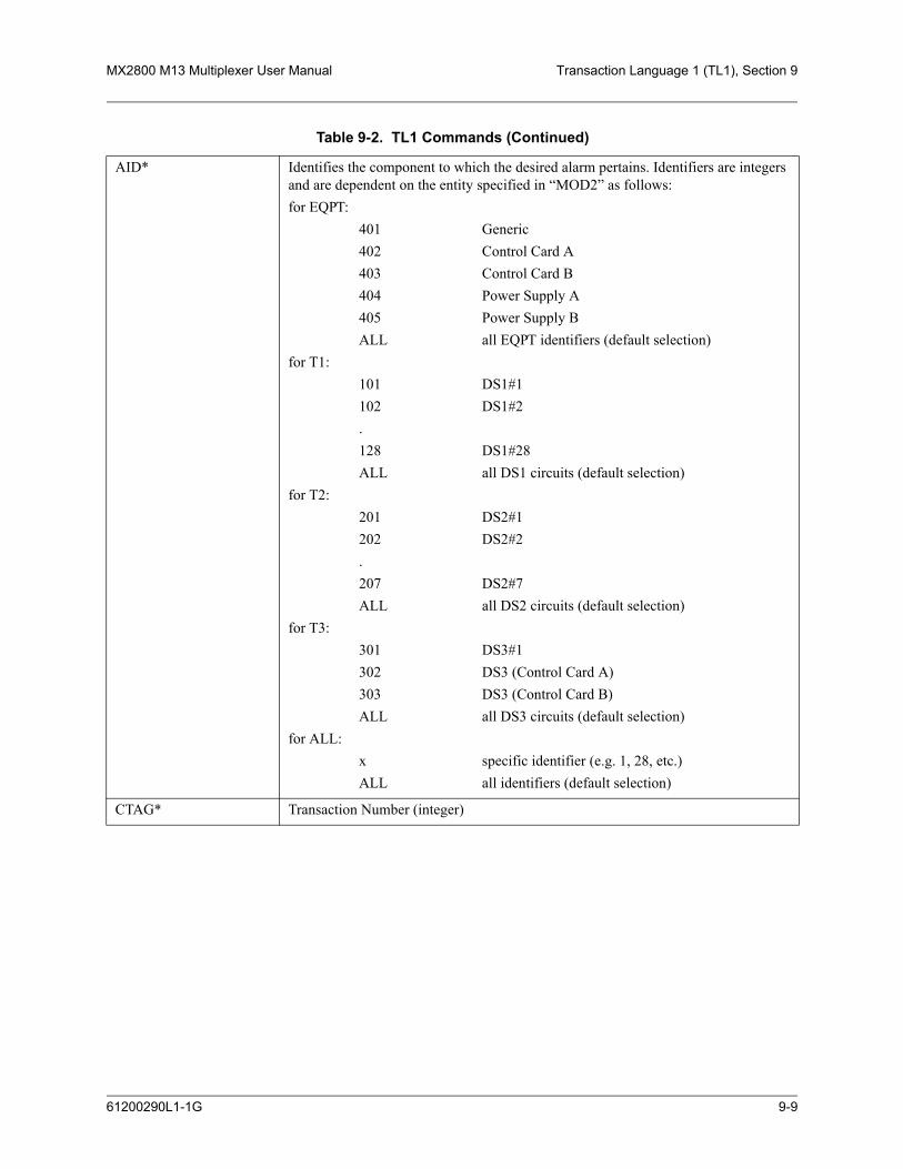
MX2800 M13 Multiplexer User Manual Transaction Language 1 (TL1), Section 9
AID* Identifies the component to which the desired alarm pertains. Identifiers are integers and are dependent on the entity specified in “MOD2” as follows:for EQPT:
401 Generic402 Control Card A403 Control Card B404 Power Supply A405 Power Supply BALL all EQPT identifiers (default selection)
for T1:101 DS1#1102 DS1#2.128 DS1#28ALL all DS1 circuits (default selection)
for T2:201 DS2#1202 DS2#2.207 DS2#7ALL all DS2 circuits (default selection)
for T3:301 DS3#1302 DS3 (Control Card A)303 DS3 (Control Card B)ALL all DS3 circuits (default selection)
for ALL:x specific identifier (e.g. 1, 28, etc.)ALL all identifiers (default selection)
CTAG* Transaction Number (integer)
Table 9-2. TL1 Commands (Continued)
61200290L1-1G 9-9

Section 9, Transaction Language 1 (TL1) MX2800 M13 Multiplexer User Manual
RTRV-COND-{EQPT|rr|ALL}:<tid>::<ctag>;
Description Retrieves the requested alarms and conditions
MOD2 Specifies what entity type to query:• EQPT General Equipment Unit• rr Facility or Circuit (i.e. T1, VT1, STS1)• ALL All entity types
TID Target ID
AID* Identifies the component to which the desired alarm pertains. Identifiers are integers and are dependent on the entity specified in “MOD2” as follows:for EQPT:
401 Generic402 Control Card A403 Control Card B404 Power Supply A405 Power Supply BALL all EQPT identifiers (default selection)
for T1:101 DS1#1102 DS1#2.128 DS1#28ALL all DS1 circuits (default selection)
for T2:201 DS2#1202 DS2#2.207 DS2#7ALL all DS2 circuits (default selection)
for T3:301 DS3#1302 DS3 (Control Card A)303 DS3 (Control Card B)ALL all DS3 circuits (default selection)
for ALL:x specific identifier (e.g. 1, 28, etc.)ALL all identifiers (default selection)
CTAG* Transaction Number (integer)
Table 9-2. TL1 Commands (Continued)
9-10 61200290L1-1G
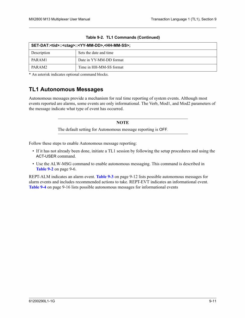
MX2800 M13 Multiplexer User Manual Transaction Language 1 (TL1), Section 9
* An asterisk indicates optional command blocks.
TL1 Autonomous MessagesAutonomous messages provide a mechanism for real time reporting of system events. Although most events reported are alarms, some events are only informational. The Verb, Mod1, and Mod2 parameters of the message indicate what type of event has occurred.
NOTEThe default setting for Autonomous message reporting is OFF.
Follow these steps to enable Autonomous message reporting:
• If it has not already been done, initiate a TL1 session by following the setup procedures and using the ACT-USER command.
• Use the ALW-MSG command to enable autonomous messaging. This command is described in Table 9-2 on page 9-6.
REPT-ALM indicates an alarm event. Table 9-3 on page 9-12 lists possible autonomous messages for alarm events and includes recommended actions to take. REPT-EVT indicates an informational event. Table 9-4 on page 9-16 lists possible autonomous messages for informational events
SET-DAT:<tid>::<ctag>::<YY-MM-DD>,<HH-MM-SS>;
Description Sets the date and time
PARAM1 Date in YY-MM-DD format
PARAM2 Time in HH-MM-SS format
Table 9-2. TL1 Commands (Continued)
61200290L1-1G 9-11

9-12 61200290L1-1G
Section 9, Transaction Language 1 (TL1)M
X2800 M13 M
ultiplexer System M
anual
Table 9-3. MX2800 Alarm Events
ction
rm is normal during DS1 loopback tests).
entering MX2800 for valid signal.
ms. If none, check settings at far-end M13
2 at far-end M13 multiplexer.
rm is normal during DS3 loopback tests.)
13 multiplexer to determine the reason it has ion.
entering the far-end M13 multiplexer.
entering the far-end M13 multiplexer the provisioned DS3 framing type).
3 at far-end M13 multiplexer.
signal at far-end M13 multiplexer.
13 multiplexer to determine the reason it has ion.
13 multiplexer to determine the reason it has ion.
gnal at DS1 ports on far-end M13 multi-
13 multiplexer to determine the reason it has ion.
gnal at DS1 ports on far-end M13 multi-
AID Notification Code
Condition Type
ServiceAffecting Location Description Recommended A
REPTALMT1
101-128 MN ACTLPBK SA NEND DS1 In-test No action. (This ala
101-128 MJ LOS SA NEND Loss Of Signal Check DS1 facility
REPTALMT2
201-207 MJ OOF SA NEND DS2 Out Of Frame Check for DS3 alarmultiplexer.
201-207 MJ RAI SA FEND DS2 Remote Alarm Indication Check status Of DS
REPT ALMT3
301 MN TSA SA NEND DS3 in-test No action (This ala
301 MN EXT-DS3 SA FEND FEND DS3 Equipment failure SA
Examine far-end Msignaled this condit
301 MN LOS SA FEND FEND DS3 Loss of Signal Check DS3 facility
301 MN OOF SA FEND FEND DS3 Out of Frame Check DS3 facility(including checking
301 MN AIS SA FEND FEND DS3 Alarm Indication Signal
Check status of DS
301 MN ISD SA FEND FEND DS3 Idle Check for DS3 idle
301 MN EXT-DS3 NSA FEND FEND DS3 Equipment Failure NSA
Examine far-end Msignaled this condit
301 MN EXT NSA FEND FEND Common Equipment Failure
Examine far-end Msignaled this condit
301 MN LOS-M SA FEND FEND Multiple DS1 Loss of Signal
Check for loss of siplexer.
301 MN EXT-DS1 SA FEND FEND DS1 Equipment Failure SA
Examine far-end Msignaled this condit
301 MN LOS-S SA FEND FEND Single DS1 Loss of Signal
Check for loss of siplexer.

MX2800 M
13 Multiplexer System
Manual
Transaction Language 1 (TL1), Section 9
61200290L1-1G 9-13
13 multiplexer to determine the reason it has ion.
entering the MX2800 for a valid signal.
ning of the DS3 framing type (M13 OR C- matches the facility. If this is correct, check ering the MX2800 for valid DS3 framing.
lity entering the far-end M13 multiplexer for ored frames.
13 multiplexer and any intermediate devices y might be sending DS3 idle toward the
Table 9-3. MX2800 Alarm Events (Continued)
ction
REPT ALMT3
301 MN EXT-DS1 NSA FEND FEND DS1 Equipment Failure NSA
Examine far-end Msignaled this condit
302(CTRL A)
CR LOS SA NEND DS3 Loss Of Signal Check DS3 facility
303(CTRL B)
302(CTRL A)
CR OOF SA NEND DS3 Out Of Frame Check The provisioBit) to make sure itthe DS3 facility ent
303(CTRL B)
302(CTRL A)
MJ RAI SA FEND DS3 Remote AlarmIndication
Check the DS3 faciAIS or severely-err
303(CTRL B)
302(CTRL A)
MN ISD SA FEND DS3 idle Check the far-end Mfor reasons why theMX2800.
303(CTRL B)
AID Notification Code
Condition Type
ServiceAffecting Location Description Recommended A

9-14 61200290L1-1G
Section 9, Transaction Language 1 (TL1)M
X2800 M13 M
ultiplexer System M
anual
card for proper LED behavior (and replace if oblem is found, call ADTRAN Technical troubleshooting details.
hich reports failure (should be indicated by a ED and the AID of the alarm).
r which TLOS is reported. Use the aid of the e card.
was removed or reset by on-site personnel.
ower supply. Use the aid of the alarm to
ower supply. Use the aid of the alarm to
Table 9-3. MX2800 Alarm Events (Continued)
ction
REPTALM
EQPT
401(GENERAL)
MN CTNEQPT NSA NEND Controller Communication Failure
Check the standby necessary). If no prSupport for further
402(CTRL A)
MN CTNEQPT NSA NEND Controller Card Failure Replace the card wflashing red ACT L
403(CTRL B)
402(CTRL A)
CR TRMT SA NEND Ds3 Transmit Loss Of Signal Replace the card foalarm to identify th
403(CTRL B)
402(CTRL A)
MN PROTNA NSA NEND Controller Card Removed Check to see if card
403(CTRL B)
404 (PS A) MN PWR NSA NEND Power Supply Failure Replace the failed pidentify the card.
405 (PS B)
404 (PS A) MN MISC NSA NEND Power SupplyCommunication Failure
Replace the failed pidentify the card.
405 (PS B)
AID Notification Code
Condition Type
ServiceAffecting Location Description Recommended A

MX2800 M
13 Multiplexer System
Manual
Transaction Language 1 (TL1), Section 9
61200290L1-1G 9-15
ower supply. Use the aid of the alarm to
ture of the MX2800's operating environment ntilation.
ture of the MX2800's operating environment ntilation.
input indicated by the AID for a blown fuse orrect wiring.
was removed by on-site personnel.
Table 9-3. MX2800 Alarm Events (Continued)
ction
REPTALM
EQPT
404 (PS A) MN PWR-5 NSA NEND Power Supply Low Replace the failed pidentify the card.
405 (PS B)
404 (PS A) MN HITEMP NSA NEND Power Supply Temp High Reduce the temperaor provide better ve
405 (PS B)
404 (PS A) MJ HITEMP NSA NEND Power Supply Temp Critical Reduce the temperaor provide better ve
405 (PS B)
404 (PS A) MN PWR-48 NSA NEND Power Supply SourceFailure
Check the –48 volt or disconnected/inc
405 (PS B)
404 (PS A) MN PROTNA NSA NEND Power Supply Card Removed Check to see if card
405 (PS B)
AID Notification Code
Condition Type
ServiceAffecting Location Description Recommended A

9-16 61200290L1-1G
Section 9, Transaction Language 1 (TL1)M
X2800 M13 M
ultiplexer System M
anual
Table 9-4. MX2800 Informational Events
Action
e coding (B8ZS/AMI) is provisioned DS1 facility. Check the DS1 facility entering mpairments which may cause line code
f this DS1 signal toward the MX2800 at (for example, an intermediate device which
S1 toward the MX2800 may transmit AIS 00 in response).
3 or DS2 alarms reported, check the status of ntering the far-end M13 multiplexer. For r end M13 multiplexer detects LOS on the ll send DS1 AIS over the DS3 toward the
S2 at the far-end M13 multiplexer.
f the DS3 signal toward the MX2800 at each example, an intermediate device which sees he DS3 toward the MX2800 may transmit X2800 in response.)
ty entering the MX2800 for problems which lar violations.
ch was not performed manually, check for ating the failure which caused the switch.
hes were not performed manually, check for ating the failure(s) which caused the
card so the new software can take effect.
AID Notification Code
Condition Type
ServiceAffecting Location Description Recommended
REPTEVT T1
101-128 EVT BPV NSA NEND Excessive DS1 Bipolar Viola-tion
Make sure the lincorrectly for this the MX2800 for iviolations.
101-128 EVT AIS NSA FEND DS1 Line AIS (LAIS) Check the status oeach DS1 device sees LOS on the Dtoward the MX28
101-128 EVT AISUONES
NSA FEND DS1 Carrier AIS (CAIS) If there are no DSthe DS1 facility eexample, if the faDS1 facility, it wiMX2800.
REPTEVT T2REPT
EVT T3
201-207 EVT AIS NSA FEND DS2 AIS Check status of D
302(CTRL A)
EVT AIS NSA FEND DS3 Alarm Indication Signal Check the status oDS3 device. (For LOS or LOF on tAIS toward the M303
(CTRL B)
302(CTRL A)
EVT BPV NSA NEND Excessive DS3 Bipolar Viola-tion
Check DS3 facilimay produce bipo
303(CTRL B)
REPTEVT
EQPT
401(GENERAL)
EVT WKSWPR NSA NEND Protection Switch If protection switother alarms indic
401(GENERAL)
EVT ESW NSA NEND Excessive Protection Switch If protection switcother alarms indicswitches.
REPTEVT
EQPT
402CTRL A
EVT PROGFLT NSA NEND Software Version Mismatch
Reset the reported
403CTRL B

MX2800 M13 Multiplexer User Manual Transaction Language 1 (TL1), Section 9
5. TL1 ERROR CODESWhen the MX2800 denies a received TL1 command, the Output Response message has an associated four letter error code indicating the reason for denial. Table 9-5 lists possible error codes.
TL1 EditingTL1 editing commands allow the MX2800 to be provisioned through a TL1 session rather than through the menu system that is accessed using a VT100 terminal emulator. User account information must be provi-sioned through a console menu session or TL1 session prior to initiating a TL1 session. Once a TL1 session has been initiated using the ACT-USER command, see Table 9-2 on page 9-6, the TL1 editing commands may be used. The standard format for an edit command is as follows:
ED-rr:<tid>:<aid>:<ctag>:::<keyword>=<value>;
The parameter descriptions are as follows:
• rr is T1, T2, T3, or EQPT
• <tid> is the Target Identifier
• <aid> is the Access Identifier
• <ctag> is a 1-to-6 character correlation tag (echoed in response)
• <keyword> is one of the entries from the data dictionaries in Table 9-6 on page 9-20, Table 9-7 on page 9-23, Table 9-8 on page 9-24, or Table 9-9 on page 9-27.
• <value> is one of the enumerated types in the data dictionaries, an integer, or Y/N, depending on the TYPE.
Table 9-5. TL1 Error Codes
Error Code Description
ICNV Input, Command Not Valid
IDRG Input, Date Range
IIAC Input, Invalid Access Identifier
IITA Input, Invalid Target Identifier
IPNV Input, Parameter Not Valid
PIUI Privilege, Input User Not Valid
PLNA Privilege, Login Not Active or Insufficient Privileges
SROF Status, Requested Operation Failed
SSRE Status, System Resources Exceeded
61200290L1-1G 9-17

Section 9, Transaction Language 1 (TL1) MX2800 M13 Multiplexer User Manual
NOTE<aid> and <ctag> are optional parameter. The placemarker : must remainin place. The default <aid> is All and the default <ctag> is 1.
TL1 Editing Examples:ED-T1:UNIT-1:106:1:::LBO=133TO266; (This would edit line build out for T1 #6 to be 133 to 266.)
ED-T2:UNIT-1:205:2:::DS2CFGMODE=T1; (This would configure T2 #5 for T1 mode versus E1.)
ED-T3:UNIT-1:300:3:::DS3MAXNUMSW=3; (This would set maximum number of switches for controller cards to 3.)
ED-EQPT:UNIT-1:400:4:::PSTEMPCRITRLY=Y; (This would enable the alarm relay for power supply temperature critical.)
To view the value of a parameter, a retrieve (RTRV) command is used. The standard format for the RTRV command is as follows:
RTRV-rr:<tid>:<aid>:<ctag>:::<keyword>;
The parameter descriptions are as follows:
• rr is T1, T2, T3, or EQPT
• <tid> is the Target Identifier
• <aid> is the Access Identifier
• <ctag> is a 1 to 6 character correlation tag (echoed in response)
• <keyword> is one of the entries from the following data dictionaries in Table 9-6 on page 9-20, Table 9-7 on page 9-23, Table 9-8 on page 9-24, or Table 9-9 on page 9-27.
NOTE<aid> and <ctag> are optional parameter. The placemarker : must remainin place. The default <aid> is All and the default <ctag> is 1.
TL1 RTRV examples:
RTRV-R1::109:4; (This would return the values for all parameters related to T1 #9.)
NOTEIf no parameter is specified, all valid parameters to the <aid> areretrieved.
RTRV-T1:UNIT-1:106:1:::LBO; (This would return the value of line build out for T1 #6.)
RTRV-T2:UNIT-1:205:2:::DS2CFGMODE; (This would return the configuration mode of T2 #5.)
9-18 61200290L1-1G
MX2800 M13 Multiplexer User Manual Transaction Language 1 (TL1), Section 9
RTRV-T3:UNIT-1:300:3:::DS3MAXNUMSW; (This would return the setting for the maximum number of switches for controller cards.)
RTRV-EQPT:UNIT-1:400:5:::PSTEMPCRITRLY; (This would return the status of the alarm relay for power supply temperature critical.)
61200290L1-1G 9-19

Section 9, Transaction Language 1 (TL1) MX2800 M13 Multiplexer User Manual
Data DictionariesThe data dictionaries that follow are to be used while performing TL1 editing or retrieve commands. Each data dictionary contains four columns. The columns are as follows:
• Keyword gives the values to be placed in the <keyword> portion of the edit command.
• Type describes the type of <value> that is required to be entered in the edit command.
– ENUM requires a text and/or number string to be entered as the <value>.
– Y/N requires a Y or N representing yes or no to be entered as the <value>.
– INT requires that an integer be entered as the <value>.
• Domain describes valid entries that may be entered into the <value> portion of the edit command.
• Description explains each of the edit or retrieve commands.
Table 9-6 contains entries that are used to edit or retrieve options for the DS3 portion of the MX2800. When performing TL1 edit commands from this table, the value of rr should be T3, and the <aid> value should be one of the following:
• 300 for all DS3 Circuits
• 301 for DS3 #1
• 302 for DS3 Control Card A
• 303 for DS3 Control Card B
Table 9-6. TL1 Editing Data Dictionary for DS3
Keyword Type Domain Description
ACTIVECONTROLLER ENUM One of the following:• A• B
Selects which controller card is active• controller card A is active• controller card B is active
CARDSWRLY Y/N Y or [N] Identifies status of System Protection Switch alarm relay• Yes (Y) - enables alarm• No (N) - disables alarm
DIAGDS3 ENUM One of the following:• DATAMODE• LINELPBK• DIGLPBK• METLPBK• REMLPBK• ALLT1
Enables the selected DS3 loopback• Refer to Data Mode on page 6-2• Refer to Line Loopback on page 6-7• Refer to Digital Loopback on page 6-7• Refer to Metallic Loopback on page 6-8• Refer to Remote Loopback on page 6-8• Refer to Remote All T1/E1 on page 6-8
DS3AISRLY Y/N Y or [N] Identifies status of DS3 AIS alarm relay• Yes (Y) - enables alarm• No (N) - disables alarm
9-20 61200290L1-1G

MX2800 M13 Multiplexer User Manual Transaction Language 1 (TL1), Section 9
DS3CVTHRS ENUM One of the following:• Disable• 1E3• 1E4• 1E5• 1E6
Indicates a limit on the number of code viola-tions accepted by the unit over the DS3 before the unit switches controller cards• 1E3 - 1 out of every 1,000 bits contains a
CV• 1E4 - 1 out of every 10,000 bits contains a
CV• 1E5 - 1 out of every 100,000 bits contains
a CV• 1E6 - 1 out of every 1,000,000 bits
contains a CV
DS3LOFRLY Y/N Y or [N] Identifies status of DS3 LOF alarm relay• Yes (Y) - enables alarm• No (N) - disables alarm
DS3LOSRLY Y/N Y or [N] Identifies status of DS3 LOS alarm relay• Yes (Y) - enables alarm• No (N) - disables alarm
DS3MAXNUMSW INT 0, 1, 2, ..., N Maximum number of times per hour the unit is allowed to switch between controller cards. If number is exceeded, the unit will issue a trap
DS3MINSWPERIOD INT 0, 1, 2, ..., N Number of seconds that must pass after a protection switch before another protection switch will be allowed
DS3PROT Y/N Y or [N] Identifies status of DS3 protection switching• Yes (Y) - enables DS3 protection switching• No (N) - disables DS3 protection switching
DS3RAIRLY Y/N Y or [N] Identifies status of DS3 RAI alarm relay• Yes (Y) - enables alarm• No (N) - disables alarm
DS3TLOSRLY Y/N Y or [N] Identifies status of DS3 TLOS alarm relayYes (Y) - enables alarmNo (N) - disables alarm
DS3XCVRLY Y/N Y or [N] Identifies status of DS3 XCV alarm relay• Yes (Y) - enables alarm• No (N) - disables alarm
Table 9-6. TL1 Editing Data Dictionary for DS3 (Continued)
Keyword Type Domain Description
61200290L1-1G 9-21

Section 9, Transaction Language 1 (TL1) MX2800 M13 Multiplexer User Manual
FMT ENUM One of the following:• CBIT• M13
Sets framing format to match the format of the receive signal at the network interface• The framing format s set to CBIT• The framing format is set to M13
LINELEN ENUM One of the following:• LONG• SHORT
Identifies Network DS3 line length• LONG - exceeds 50 feet.• SHORT - less than 50 feet.
RMTLPBK ENUM One of the following:• DISABLE• EITHER• FEAC• CBIT
Indicates whether the unit will respond to remote loopbacks over FEAC, CBIT, EITHER, or if remote loopbacks are disabled• DISABLE - do not respond• EITHER - respond over either FEAC or
CBIT• FEAC - respond over FEAC• CBIT - respond over CBIT
SYSCARDARLY Y/N Y or [N] Identifies status of System Controller Card A alarm relay• Yes (Y) - enables alarm• No (N) - disables alarm
SYSCARDBRLY Y/N Y or [N] Identifies status of System Controller Card B alarm relay• Yes (Y) - enables alarm• No (N) - disables alarm
SYSCARDCOMMRLY Y/N Y or [N] Identifies status of System Communication Fail alarm relay• Yes (Y) - enables alarm• No (N) - disables alarm
SYSCARDRLY Y/N Y or [N] Identifies status of System Controller Card alarm relay• Yes (Y) - enables alarm• No (N) - disables alarm
TMG ENUM One of the following:• LPD• INT
Identifies timing supply for the DS3• LPD - loop timed• INT - internal timing source
Table 9-6. TL1 Editing Data Dictionary for DS3 (Continued)
Keyword Type Domain Description
9-22 61200290L1-1G

MX2800 M13 Multiplexer User Manual Transaction Language 1 (TL1), Section 9
Table 9-7 contains entries that are used to edit or retrieve options for the DS2 portion of the MX2800. When performing TL1 edit commands from this table, the value of rr should be T2 and the <aid> value should be one of the following:
201 - DS2#1
202 - DS2#2
.
.
.
207 - DS2#7
Table 9-7. TL1 Editing Data Dictionary for DS2
Keyword Type Domain Description
DIAGDS2TESTSTATE ENUM One of the following:• DATAMODE• NETWORK
Identifies DS2 Diagnostic Loopback• NETWORK selects the available loopback• DATAMODE ends a test in progress
DS2AISRLY Y/N Y or [N] Identifies status of DS2 AIS alarm relay• Yes (Y) - enables alarm• No (N) - disables alarm
DS2CFGMODE ENUM One of the following:• T1• E1
Identifies DS2 Configuration• T1 sets DS2 configuration to M12 (4xT1).• E1 sets DS2 configuration to G.747
(3xE1).
DS2LOSRLY Y/N Y or [N] Identifies status of DS2 LOS alarm relay• Yes (Y) - enables alarm• No (N) - disables alarm
DS2RAIRLY Y/N Y or [N Identifies status of DS2 RAI alarm relay• Yes (Y) - enables alarm• No (N) - disables alarm
61200290L1-1G 9-23

Section 9, Transaction Language 1 (TL1) MX2800 M13 Multiplexer User Manual
Table 9-8 contains entries that are used to edit or retrieve options for the DSX portion of the MX2800. When performing TL1 edit commands from this table, the value of rr should be T1, and the <aid> value should be one of the following:
101 - DS1#1
102 - DS1#2
.
.
.
128 - DS1#28
Table 9-8. TL1 Editing Data Dictionary for DS1
Keyword Type Domain Description
DIAGDSXTESTSTATE ENUM One of the following:• DATAMODE• TRIBUTARY• ANALOGNET• DIGNET• CODEC• REMLPBK• CSULPBK• CSUBERT• LINEBERT
Identifies DSX Diagnostic Loopbacks. Choose an available loopback• Refer to Data Mode on page 6-2• Refer to Tributary on page 6-2• Refer to Analog Network on page 6-3• Refer to Digital Line/Net on page 6-3• Refer to Codec Line/Net on page 6-4• Refer to Remote Loopback on page 6-4• Refer to CSU Loopback on page 6-4• Refer to CSU Loopback w/BERT on
page 6-4• Refer to Line BERT on page 6-5
DSXCAISRLY Y/N Y or [N] Identifies status of DSX CAIS alarm relay. • Yes (Y) - enables alarm• No (N) - disables alarm
DSXCFGLINESWPROT ENUM One of the following:• DISABLE• ENABLE• UNAVAIL
Identifies the state of the DSX Switch Protection• DISABLE - the switch is disabled• ENABLE - the switch is enabled• UNAVAIL - the switch is not in the
configuration
9-24 61200290L1-1G

MX2800 M13 Multiplexer User Manual Transaction Language 1 (TL1), Section 9
DSXCFGSTATE ENUM One of the following:• DISABLE• ENABLE• UNAVAIL• AUTO
Identifies the DSX configuration state• DISABLE - disables the current
configuration• ENABLE - enable the newest
configuration• UNAVAIL - the configuration is
unavailable• AUTO - the configuration is set to auto
save in nonvolatile memory
DSXCVTHRS ENUM One of the following:• DISABLE• 1E3• 1E4• 1E5• 1E6
Indicates a limit on the number of code violations accepted by the unit over a single T1/E1 before the unit switches controller cards• 1E3 - 1 out of every 1,000 bits on a sin-
gle T1/E1 contains a CV• 1E4 - 1 out of every 10,000 bits on a
single T1/E1 contains a CV• 1E5 - 1 out of every 100,000 bits on a
single T1/E1 contains a CV• 1E6 - 1 out of every 1,000,000 bits on a
single T1/E1 contains a CV
DSXLAISRLY Y/N Y or [N] Identifies status of DSX LAIS alarm relay• Yes (Y) - enables alarm• No (N) - disables alarm
Table 9-8. TL1 Editing Data Dictionary for DS1 (Continued)
Keyword Type Domain Description
61200290L1-1G 9-25

Section 9, Transaction Language 1 (TL1) MX2800 M13 Multiplexer User Manual
DSXLBKDETECTION ENUM One of the following:• DISABLE• CSU• NIU• M13INBAND• UNAVAIL
Identifies for each T1/E1 interface whether the T1/E1 will respond to loopback requests• DISABLE - does not respond to
loopback tests• CSU - cause the channel to loop up or
loop down when it receives a CSU loop-up or loop-down pattern for more than 5 seconds
• NIU - cause the channel to loop up or loop down when it receives an NIU loop-up or loop-down pattern for more than 5 seconds
• M13INBAND - cause the channel to loop up or loop down when it receives an M13INBAND loop-up or loop-down pattern for more than 5 seconds
• UNAVAIL - T1/E1 not available for loopback tests
DSXLOSRLY Y/N Y or [N] Identifies status of DSX LOS alarm relay• Yes (Y) - enables alarm• No (N) - disables alarm
DSXPROTTHRS INT 1-28 Number of Enabled lines that must fail before a protection switch occurs
DSXXCVRLY Y/N Y or [N] Identifies status of DSX XCV alarm relay• Yes (Y) - enables alarm• No (N) - disables alarm
LBO ENUM One of the following:• 0TO133• 133TO266• 266TO399• 399TO533• 533TO655• MINUS7R5• E10TO3000• UNAVAIL
Identifies the line length for each T1 inter-face according to the distance from the MX2800 to the DTE device• 0TO133, 133TO266, 266TO399,
399TO533, 533TO655 - distance in feet• MINUS7R5 - -7.5dB length• E10TO3000 - setting for E1• UNAVAIL - unavailable
Table 9-8. TL1 Editing Data Dictionary for DS1 (Continued)
Keyword Type Domain Description
9-26 61200290L1-1G

MX2800 M13 Multiplexer User Manual Transaction Language 1 (TL1), Section 9
Table 9-9 contains entries that are used to edit or retrieve options for the equipment portion of the MX2800. When performing TL1 edit commands from this table, the value of rr should be EQPT, and the <aid> value should be one of the following:
400 - All EQPT identifiers
401 - Generic
402 - Control Card A
403 - Control Card B
404 - Power Supply A
405 - Power Supply B
LINECDE ENUM One of the following:• AMI• B8ZS• E1AMI• E1HDB3• UNAVAIL
Identifies line code for T1/E1s to match connected devices• AMI - set T1 to AMI• B8ZS - Sets T1 to B8ZS• E1AMI - sets E1 to AMI• E1HDB3 - sets E1 to HDB3• UNAVAIL - no T1/E1 available
Table 9-9. TL1 Editing Data Dictionary for EQPT
Keyword Type Domain Description
DIAGBERCLEARCOUNT Y/N Y or [N] Clears BERT count• Yes (Y) - clears the BERT count• No (N) - does not clear the BERT count
DIAGBERTCOUNT INT 0, 1, 2, ..., N Error count
DIAGBERTSYNC ENUM One of the following:• NOSYNC• SYNC
Identifies state of Pattern Synchronization• NOSYNC - there is no pattern sync• SYNC - pattern sync is available
Table 9-8. TL1 Editing Data Dictionary for DS1 (Continued)
Keyword Type Domain Description
61200290L1-1G 9-27

Section 9, Transaction Language 1 (TL1) MX2800 M13 Multiplexer User Manual
DIAGLPBKTIMEOUT ENUM One of the following:• DISABLE• 1-MIN• 5-MINL• 10-MIN• 15-MIN• 30-MIN• 45-MIN• 1-HR• 2-HR
Identifies the amount of time before a Diagnostic Loopback will time out• DISABLE - timeout is disabled• 1-MIN - timeout value is one minute• 5-MINL - timeout value is five minutes• 10-MIN - timeout value is ten minutes• 15-MIN - timeout value is 15 minutes• 30-MIN - timeout value is 30 minutes• 45-MIN - timeout value is 45 minutes• 1-HR - timeout value is 60 minutes• 2-HR - timeout value is 120 minutes
DIAGRESET Y/N Y or [N] Resets Diagnostic Loopbacks• Yes (Y) - reset the diagnostic loopback• No (N) - do not reset the diagnostic
loopback
PSBATTERYLOWRLY Y/N Y or [N] Identifies status of Power Supply Battery Low alarm relay• Yes (Y) - enables alarm• No (N) - disables alarm
PSCHARGERFAILRLY Y/N Y or [N] Identifies status of Power Supply Charger Fail alarm relay• Yes (Y) - enables alarm• No (N) - disables alarm
PSFANFAILRLY Y/N Y or [N] Identifies status of Power Supply Fan Fail alarm relay• Yes (Y) - enables alarm• No (N) - disables alarm
PSMALFNCRLY Y/N Y or [N] Identifies status of Power Supply Malfunction alarm relay• Yes (Y) - enables alarm• No (N) - disables alarm
PSPOWERFAILRLY Y/N Y or [N] Identifies status of Power Supply Power Fail alarm relay• Yes (Y) - enables alarm• No (N) - disables alarm
Table 9-9. TL1 Editing Data Dictionary for EQPT (Continued)
Keyword Type Domain Description
9-28 61200290L1-1G

MX2800 M13 Multiplexer User Manual Transaction Language 1 (TL1), Section 9
PSPOWERLOWRLY Y/N Y or [N] Identifies status of Power Supply Power Low alarm relay• Yes (Y) - enables alarm• No (N) - disables alarm
PSTEMPCRITRLY Y/N Y or [N] Identifies status of Power Supply Temper-ature Critical alarm relay• Yes (Y) - enables alarm• No (N) - disables alarm
PSTEMPHIGHRLY Y/N Y or [N] Identifies status of Power Supply Temper-ature High alarm relay• Yes (Y) - enables alarm• No (N) - disables alarm
Table 9-9. TL1 Editing Data Dictionary for EQPT (Continued)
Keyword Type Domain Description
61200290L1-1G 9-29

Section 9, Transaction Language 1 (TL1) MX2800 M13 Multiplexer User Manual
TL1 Loopback CommandsThe OPR-LPBK and RLS-LPBK commands are provided as an alternative to ED commands to perform loopbacks through TL1. The general format for these commands is as follows:
OPR-LPBK-{T1|T2|T3}:<tid>:<aid>:<ctag>::<locn>,,,<lpbktype>;
RLS-LPBK-{T1|T2|T3}:<tid>:<aid>:<ctag>::<locn>,,,<lpbktype>;
Table 9-10 describes each of the DS3 loopbacks that can be initiated or released with these commands.
1. The value of xy may be 00 through 03.
Table 9-11 describes each of the DS2 loopbacks that can be initiated or released with these commands.
* The value of xy may be 01 through 07, corresponding to the desired DS2 channel.
Table 9-10. DS3 TL1 Loopback Commands
Verb MOD2 <aid>1 <locn> <lpbktype> Description
OPR T3 3xy NEND LINE Initiates the DS3 Line Loopback
RLS T3 3xy NEND LINE Releases the DS3 Line Loopback
OPR T3 3xy NEND DIGLPBK Initiates the DS3 Digital Loopback
RLS T3 3xy NEND DIGLPBK Releases the DS3 Digital Loopback
OPR T3 3xy NEND TERMINAL Initiates the DS3 Network Loopback
RLS T3 3xy NEND TERMINAL Releases the DS3 Network Loopback
OPR T3 3xy FEND LINE Initiates the DS3 Remote Loopback
RLS T3 3xy FEND LINE Releases the DS3 Remote LoopbacK
OPR T3 3xy FEND ALLT1 Initiates the DS3 All T1/E1 Loopback
RLS T3 3xy FEND ALLT1 Releases the DS3 All T1/E1 Loopback
RLS T3 3xy Releases any active DS3 Loopback
Table 9-11. DS2 TL1 Loopback Commands
Verb MOD2 <aid>* <locn> <lpbktype> Description
OPR T2 2xy NEND NETWORK Initiates the DS2 Network Loopback
RLS T2 2xy NEND NETWORK Releases the DS2 Network Loopback
RLS T2 2xy Releases any active DS2 Loopback
9-30 61200290L1-1G

MX2800 M13 Multiplexer User Manual Transaction Language 1 (TL1), Section 9
Table 9-12 describes each of the DS1 loopbacks that can be initiated or released with DS1 TL1 loopback commands.
* The value of xy may be 01 through 28, corresponding to the desired DS1 channel.
Table 9-12. DS1 TL1 Loopback Commands
Verb MOD2 <aid>* <locn> <lpbktype> Description
OPR T1 1xy NEND NETWORK Initiates the DS1 Tributary Loopback
RLS T1 1xy NEND NETWORK Releases the DS1 Tributary Loopback
OPR T1 1xy NEND TERMINAL Initiates the DS1 Analog Loopback
RLS T1 1xy NEND TERMINAL Releases the DS1 Analog Loopback
OPR T1 1xy NEND DIGNET Initiates the DS1 Digital Line/Net Loopback
RLS T1 1xy NEND DIGNET Releases the DS1 Digital Line/Net Loopback
OPR T1 1xy NEND CODEC Initiates the DS1 Codec Line/Net Loopback
RLS T1 1xy NEND CODEC Releases the DS1 Codec Line/Net Loopback
OPR T1 1xy FEND DS1FEAC Initiates the DS1 Remote Loopback
RLS T1 1xy FEND DS1FEAC Releases the DS1 Remote Loopback
OPR T1 1xy FEND CSULPBK Initiates the DS1 CSU Loopback
RLS T1 1xy FEND CSULPBK Releases the DS1 CSU Loopback
OPR T1 1xy FEND CSUBERT Initiates the DS1 CSU Loopback w/BERT
RLS T1 1xy FEND CSUBERT Releases the DS1 CSU Loopback w/BERT
RLS Releases any active DS1 Loopback
61200290L1-1G 9-31

Section 9, Transaction Language 1 (TL1) MX2800 M13 Multiplexer User Manual
9-32 61200290L1-1G

APPENDIX A, ACCEPTANCE TEST PROCEDURE
Appendix AAcceptance Test Procedure
1. INTRODUCTIONThis appendix describes the procedures to be used in performing acceptance testing of ADTRAN’s Total Access MX2800 M13 Multiplexer. It is assumed that the MX2800 has already been installed, powered-up, equipped and cabled to the DSX-1 and DSX-3 or connecting equipment according to the specifications described in Section 2, Installation and Operation and local operating company procedures.
The MX2800 is an M13 multiplexer used to consolidate 28 DS1 circuits on to a DS3. The unit can be equipped in various ways. In general, this section addresses the following areas:
• Verifying the options installed on the unit
• Configuring the unit for test
• Testing all DS1 and DS3 circuits to make sure that each circuit passes error free data
• Verifying that alarms are generated and passed to external alarm systems
• Testing the system power supply and controller card redundancy
• Restoring the unit to the desired configuration
• Configuring the unit for customer traffic
• Completing the Acceptance Test Procedures (ATP) Checklist
2. VERIFYING THE INSTALLED OPTIONSThe installed configuration determines the level of redundancy the unit supports. There may be one or two Power Supply Units (PSUs) and Controller Card Units (CCUs) present. A single PSU and CCU are required for operation without redundancy. Equipping the shelf with two of each provides full redundancy. The PSUs are the smaller modules on the left side. The CCUs are the larger modules toward the center and right of the shelf. Visually note which cards are installed in the chassis under test.
61200290L1-1G A-1

Appendix A, Acceptance Test Procedure MX2800 M13 Multiplexer User Manual
3. CONFIGURING THE SYSTEMBefore the required tests can be performed, a minimal amount of configuration must be performed on the MX2800. It is necessary to gain access to the Provisioning menus through the Craft Port, then set the desired parameters for the DS1 ports, the DS3 port, and the alarm attributes. The following paragraphs step through the process.
Accessing the Craft PortThe MX2800 is shipped with a flat silver-satin cable that plugs into the Craft jack on the front panel and a DB-9 adapter that allows the cable to plug into the COM port on a computer or dumb terminal. Make these connections, then start up a terminal emulation program on a computer (e.g., HyperTerminal, Procomm, Crosstalk, etc.), using VT100 emulation with a character format of 9600 baud, no parity, eight bits, and one stop bit. Press the ENTER key several times. A username prompt should appear. The default username is “username”. The default password is “password”. The input characters for username and password are not case sensitive. After the logon and password are accepted, the MX2800 Main Menu should appear. This is the screen from which all other management and control functions are accessible.
Provisioning the DS3 PortIn order for the MX2800 to correctly pass traffic through the system, the DS3 and DS1 ports need to be properly configured. The provisioning of the DS3 port is covered in this subsection, and the provisioning of the DS1 ports is covered in the next.
NOTEThe ENTER key is used to select a function, and the ESC key is used toback up a level in the menu system.
Follow these procedures to configure DS3 ports.
1. From the Main Menu, select Configuration, and then select Network Interface. The Network Configuration screen should appear. Set each of the options on this screen as referenced below.
If this card is installed... Check
Power Supply A (far left slot) installed?
Power Supply B (next slot to right) installed
Controller A (lower controller card) installed
Controller A (upper controller card) installed
A-2 61200290L1-1G

MX2800 M13 Multiplexer User Manual Acceptance Test Procedure, Appendix A
NOTETo change an option, simply enter the corresponding number, pressENTER, and follow the prompts.
DS3 Configuration• Framing = C-Bit (default = M13)
• Line Length = Use 0-225 ft. (default) or 225-450 ft., depending on the distance to the DS3 Cross connect panel or connecting equipment.
• Timing = Local (default = Loop)
NOTEWhen performing tests to a DS3 loopback, the timing must be set to Localto guarantee DS3 frame synchronization and error-free testing during biterror tests. Normal operation generally requires that this attribute be setback to Loop (system default) after all acceptance tests are completed.One exception to the rule is when connecting two MX2800s together on aback-to-back basis (DS3s facing one another). In that case, one MX2800must be set to Local and the other to Loop.
• Remote Loopbacks = FEAC/C-Bit (default)
• XCV Threshold = Disabled (default)
Protection Configuration• Active Controller = A (default)
• Network Protection = Disabled (default)
• Max Switch Threshold = 3 (default)
• Min. Switching Period (sec.) = 10 (default)
Miscellaneous• Loopback Time Out = 5 min. (default)
DS2 Configuration• DS2 #1 = M12(4xT1)
• DS2 #2 = M12(4xT1)
• DS2 #3 = M12(4xT1)
• DS2 #4 = M12(4xT1)
• DS2 #5 = M12(4xT1)
61200290L1-1G A-3
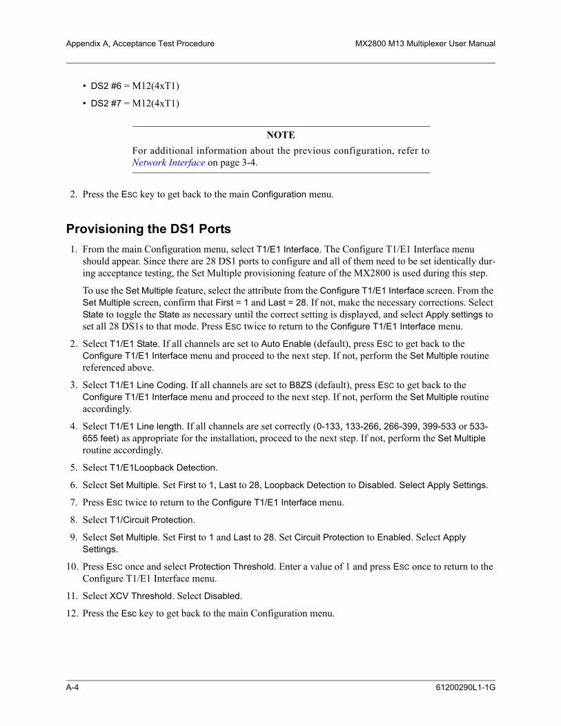
Appendix A, Acceptance Test Procedure MX2800 M13 Multiplexer User Manual
• DS2 #6 = M12(4xT1)
• DS2 #7 = M12(4xT1)
NOTEFor additional information about the previous configuration, refer toNetwork Interface on page 3-4.
2. Press the ESC key to get back to the main Configuration menu.
Provisioning the DS1 Ports1. From the main Configuration menu, select T1/E1 Interface. The Configure T1/E1 Interface menu
should appear. Since there are 28 DS1 ports to configure and all of them need to be set identically dur-ing acceptance testing, the Set Multiple provisioning feature of the MX2800 is used during this step.
To use the Set Multiple feature, select the attribute from the Configure T1/E1 Interface screen. From the Set Multiple screen, confirm that First = 1 and Last = 28. If not, make the necessary corrections. Select State to toggle the State as necessary until the correct setting is displayed, and select Apply settings to set all 28 DS1s to that mode. Press ESC twice to return to the Configure T1/E1 Interface menu.
2. Select T1/E1 State. If all channels are set to Auto Enable (default), press ESC to get back to the Configure T1/E1 Interface menu and proceed to the next step. If not, perform the Set Multiple routine referenced above.
3. Select T1/E1 Line Coding. If all channels are set to B8ZS (default), press ESC to get back to the Configure T1/E1 Interface menu and proceed to the next step. If not, perform the Set Multiple routine accordingly.
4. Select T1/E1 Line length. If all channels are set correctly (0-133, 133-266, 266-399, 399-533 or 533-655 feet) as appropriate for the installation, proceed to the next step. If not, perform the Set Multiple routine accordingly.
5. Select T1/E1Loopback Detection.
6. Select Set Multiple. Set First to 1, Last to 28, Loopback Detection to Disabled. Select Apply Settings.
7. Press ESC twice to return to the Configure T1/E1 Interface menu.
8. Select T1/Circuit Protection.
9. Select Set Multiple. Set First to 1 and Last to 28. Set Circuit Protection to Enabled. Select Apply Settings.
10. Press ESC once and select Protection Threshold. Enter a value of 1 and press ESC once to return to the Configure T1/E1 Interface menu.
11. Select XCV Threshold. Select Disabled.
12. Press the Esc key to get back to the main Configuration menu.
A-4 61200290L1-1G

MX2800 M13 Multiplexer User Manual Acceptance Test Procedure, Appendix A
Alarm Relay ConfigurationAlthough there are numerous alarm configuration options available on the MX2800, the ability to generate only one Critical and one Noncritical alarm are the only requirements for this part of the acceptance test process. These requirements confirms that the alarm contacts are wired and operating correctly and trans-mitting the appropriate alarm conditions back to the central office alarm panel.
1. From the main Configuration menu, select System Management.
2. Select Alarm Relay Configuration to get to the Alarm Relay Configuration screen.
3. As necessary, toggle the DS3 LOS state to Enabled, thus forcing generation of a Critical alarm when the DS3 port sees a Loss of Signal condition.
4. As necessary, toggle the LOS state to Enabled, thus forcing generation of a Noncritical alarm when a DS1 port sees a Loss of Signal condition.
5. Toggle the SAVE CONFIG state.
4. VERIFYING THE DATA INTEGRITYNow that the system has been properly provisioned for acceptance testing, proceed with the testing of the system. The first key test is to verify that the MX2800 can pass traffic between the DS1 and DS3 ports. Three different methods of testing are presented. One of the three should be selected based on test equip-ment availability and network configuration. All of the tests are performed at the DSX-1 and DSX-3 cross-connect bays or connecting equipment so that both the MX2800 circuitry and the office cabling are tested. If problems are encountered during testing, refer to Section 4, Status and Section 5, Statistics for assistance with problem determination.
DS1 Daisy-Chain to DS3 (Hard) LoopbackThis test can be performed single-handedly, and it can be used only if DS1s are terminated at the DSX1. It loads all 28 ports of the MX2800 with traffic at the same time, but it does not confirm DS3 cabling integ-rity (transmit Vs. receive).
Equipment Required:
• 1 DS1 test set for running a BERT
• 28 DS1 bantam test cords
• 1 DS3 test cord
Follow these procedures to test the daisy-chain.
1. At the DSX-3 cross-connect panel or connecting equipment, loop the DS3 from the MX2800 back on itself. Confirm that the MX2800 sees a good DS3 signal. The DS3 STATUS LED should be solid green on the Active Controller, and the DS3 test set should be in frame synchronization with the MX2800.
2. At the DSX-1 cross-connect panel, insert the Transmit output of the DS1 test set into the Input of the first DS1 channel of the MX2800.
61200290L1-1G A-5

Appendix A, Acceptance Test Procedure MX2800 M13 Multiplexer User Manual
3. At the DSX-1, install a bantam test cord from the Output of the first DS1 channel to the Input of the second; then connect a second bantam test cord from the Output of the second DS1 channel to the Input of the third DS1 channel. Repeat this procedure for all 28 DS1 channels.
4. Connect the Output of the 28th DS1 channel to the Receive input of the DS1 test set.
5. Set the test set options for ESF/B8ZS, and run a standard BERT using QRSS or other preferred test pattern(s).
6. All alarms should clear on the MX2800, and the BERT should run error free. Troubleshoot as necessary.
7. Leave this test setup in place, as it will be used during the redundancy testing portion of this document. Proceed to Verifying Alarm Notification on page A-7.
DS1 to DS3 Head-to-Head TestThis test is ordinarily a two-person operation, and it is the preferred means of testing system and cabling integrity. It tests one DS1 channel at a time, using a DS1 test set at the DSX-1 cross-connect panel or connecting equipment and a DS3 test set at the DSX-3 or connecting equipment location.
Equipment Required:
• 1 DS1 test set capable of running a BERT
• 1 DS3 test set capable of accessing and running a BERT on a single DS1
Follow these procedures to execute the head-to-head test.
1. At the DSX-3 cross-connect panel or connecting equipment, properly connect the DS3 test set to the DS3 coming from the MX2800. Confirm transmit and receive integrity, an integral step in the process.
2. Configure the DS3 test set for C-Bit Framing, the appropriate LBO, and set to drop out DS1 #1. Configure the DS1 BERT to run in ESF/B8ZS mode using QRSS or other preferred test pattern. Confirm that the MX2800 sees a good DS3 signal. The DS3 STATUS LED should be solid green on the Active Controller, and the DS3 test set should be in frame synchronization with the MX2800.
3. At the DSX-1 cross-connect bay or connecting equipment, connect the DS1 test set to the first DS1 channel of the MX2800. Configure the test set for the same framing, line code, and BERT pattern as the DS3 test set. Confirm a good, error-free BERT for a minimal period, such as 15 seconds.
4. Repeat for DS1 channels 2-28 by moving the DS1 test cables and reconfiguring the DS3 test set to drop out the appropriate DS1 channel under test.
5. The MX2800 condition is in an alarm because of the previously tested and now unterminated DS1 ports, but this should not prohibit a successful BERT between the DS1 and DS3 test sets on the channel under test.
6. Leave this test setup in place, as it will be used during the redundancy testing portion of this document. Proceed to Verifying Alarm Notification on page A-7.
A-6 61200290L1-1G

MX2800 M13 Multiplexer User Manual Acceptance Test Procedure, Appendix A
DS1 to DS3 (Hard) LoopbackThis test requires minimal test equipment, tests one DS1 at a time, and can be performed single-handedly. It does not verify DS3 cabling integrity (transmit Vs. receive) to the DSX3 or connecting equipment.
Equipment Required:
• 1 DS1 test set capable of running a BERT test
• 1 DS3 DSX test cord
Follow these procedures to test one DS1 at a time:
1. At the DSX-3 cross-connect panel or connecting equipment, loop the DS3 from the MX2800 back on itself. Confirm that the MX2800 sees a good DS3 signal. The DS3 STATUS LED should be solid green on the Active Controller, and the DS3 test set should be in frame synchronization with the MX2800.
2. At the DSX-1 cross-connect bay or connecting equipment, insert the Transmit output of the DS1 test set to the DS1 Input of the first channel of the MX2800. Connect the Receive input of the test set to the Output of the first DS1 channel of the MX2800.
3. Configure the DS1 test set for ESF/B8ZS and the desired BERT pattern, such as QRSS.
4. All alarms should clear on the MX2800, and the BERT should run error free. Troubleshoot as necessary.
5. Repeat the above procedure for DS1 channels 2-28. The MX2800 will be in an alarm condition because of the unterminated DS1 ports, but this condition should not prohibit a successful BERT.
6. Leave this test setup in place, as it will be used during the redundancy testing portion of this document. Proceed to Verifying Alarm Notification.
5. VERIFYING ALARM NOTIFICATIONThe MX2800 has two sets of alarm relay contacts available for connection to external alarm systems. They are located on the back panel and are designated as Critical, and Noncritical. Normally Open and normally Closed contacts are available for each of the relay outputs. The Critical alarm is activated when the DS3 port experiences a Loss of Signal (LOS) event. The Noncritical alarm is activated when one of the 28 DS1 ports experiences a Loss of Signal event. Detailed alarm testing procedures are described below.
Critical Alarm Relay TestThis test actuates the Critical alarm relay contacts.
Equipment Required:
• 1 DS3 DSX test cord
Follow these procedures to test one the critical alarm relay.
1. Ensure that the DS3 is not in alarm. To do this, place a hard loopback of the DS3 toward the MX2800 using a test cord at the DSX-3 cross-connect panel or connecting equipment.
2. With the loopback in place, all alarms should clear on the Controller Module DS3 port. The DS3 STATUS LED should be solid green on the Active Controller).
61200290L1-1G A-7

Appendix A, Acceptance Test Procedure MX2800 M13 Multiplexer User Manual
3. Remove the loopback from the DS3 and ensure that no other DS3 signal is entering the MX2800 through the DSX-3 cross-connect bay or connecting equipment, such as DCS.
4. The MX2800 should go into Critical alarm, thus closing the relay contacts and sending the alarm to the alarm monitoring equipment.
5. Verify that the alarm is being properly reported as a Critical alarm.
Noncritical Alarm Relay TestThis test actuates the Noncritical alarm relay contacts.
Equipment Required:
• 1 DS3 DSX test cord
Follow these procedures to test one the noncritical alarm relay.
1. Ensure that the DS3 is not in alarm. The DS3 STATUS LED should be solid green on the Active Con-troller. To do this, re-install a hard loopback of the DS3 toward the MX2800.
2. Ensure that the 28 DS1s are out of alarm. To accomplish this, proceed as follows:
a. At the DSX-1 cross-connect, insert the Transmit of the DS1 test set into the Input of the first DS1 channel of the MX2800. Install a bantam test cord from the Output of the first DS1 channel to the Input of the second DS1 channel. Then connect a second bantam test cord from the Output of the second DS1 channel to the Input of the third DS1.
b. Repeat this procedure for all 28 DS1 channels. Connect the Output of the 28th DS1 channel to the Receive of the DS1 test set. Configure the test set for ESF/B8ZS and run a standard BERT test using QRSS or other preferred test pattern(s).
3. Nothing should be in alarm. The DS1 STATUS LEDs should all be solid green on the Active Controller. Remove any one of the bantam cords from the DSX bay. Removing this cord causes a DS1 LOS alarm, which results in the actuation of the Noncritical alarm relay.
4. Verify that the Noncritical alarms are being properly reported to the office alarm monitoring equipment.
6. VERIFYING SYSTEM REDUNDANCYThis section addresses the redundancy features of the MX2800. The MX2800 supports redundancy of both the Power Supply and Controller Modules. The equipment configuration (nonredundant vs. redundant and type of power redundancy) are useful in determining what can and cannot be tested. The following sections describe the tests for various configurations.
Power Supply RedundancyWhen installed, the MX2800 can be wired to have either one or two –48 VDC power feeds A and B. In addition, the MX2800 chassis can be equipped with either one or two Power Supply modules. Test scenar-ios for the two most common configurations follow. Testing of the other configurations is a subset of the following.
A-8 61200290L1-1G

MX2800 M13 Multiplexer User Manual Acceptance Test Procedure, Appendix A
Single Power Supply Module / Dual Power FeedsWhen the MX2800 is equipped with only a single Power Supply module, there is no protection against a failure of the module itself. However, the single Power Supply is capable of utilizing the A and B power feeds to protect against a failure in one of the power sources feeding the shelf. To verify that the MX2800 is properly utilizing the A and B power feeds, the following procedure is recommended:
1. With the MX2800 installed and operating normally, go to the fuse panel at the top of the bay and remove the fuse corresponding to the A power feed for the MX2800 shelf. Removing this fuse should have no effect on the operation of the shelf because the MX2800 is operating on the B power feed.
2. Reinsert the fuse for the A power feed.
3. Now, remove the B power feed fuse for the MX2800 shelf. Once again, there should be no effect on the operation of the shelf because the MX2800 is operating on the A power feed.
4. Reinsert the fuse for the B power feed.
Dual Power Supply Modules / Dual Power FeedsWhen the MX2800 is equipped with two Power Supply modules and also wired to support dual power feeds, the shelf is protected against a failure of either of the Power Supply cards or a failure of one of the power sources feeding the shelf. Use the following procedure to confirm the operation of this fully redun-dant configuration:
1. With the MX2800 installed and operating normally, remove the A Power Supply card (the one on the left). Removing this card should have no effect on the operation of the shelf because the MX2800 is operating on the B Power Supply.
2. Go to the fuse panel at the top of the bay and remove the fuse corresponding to the A power feed. Removing this fuse should have no effect on the operation of the shelf because the B Power Supply is running on the B power feed.
3. Reinsert the fuse for the A power feed.
4. Remove the fuse corresponding to the B power feed to the shelf. Doing so should have no effect on the operation of the shelf as the B Power Supply is operating on the A power feed.
5. Reinsert the fuse for the B power feed.
6. Reinsert the A Power Supply into the MX2800 chassis.
7. Remove the B Power Supply card (the one on the right). Doing so should have no effect on the operation of the shelf because the MX2800 is operating on the A Power Supply.
8. Go to the fuse panel at the top of the bay and remove the fuse corresponding to the A power feed. Removing this fuse should have no effect on the operation of the shelf because the A Power Supply is now running on the B power feed.
9. Reinsert the fuse for the A power feed.
10. Remove the fuse corresponding to the B power feed to the shelf. Removing this fuse should have no effect on the operation of the shelf as the A Power Supply is operating on the A power feed.
11. Reinsert the fuse for the B power feed.
12. Reinsert the B Power Supply into the MX2800 chassis.
61200290L1-1G A-9

Appendix A, Acceptance Test Procedure MX2800 M13 Multiplexer User Manual
13. Confirm that both power supplies and power feeds are functioning as normal. Front panel LEDs identify problems with the power supplies, but the inputs can be tested only via VOM.
Controller Card RedundancyThe MX2800 can be equipped with either one or two Controller cards. The Controller contains all of the MX2800's critical circuitry, including the DS3 interface, DS1 interfaces, management and communica-tions hardware/firmware, etc. If the MX2800 is equipped with only one Controller, there is no protection against failure. If a failure does occur to the Controller, an alarm is initiated; and the front panel LEDs reflect the condition. The ACT LED is either solid or flashing red.
If the MX2800 is equipped with two Controller modules, all traffic is protected and can be switched over to the Standby Controller in the event of a card failure. The following procedures demonstrate the functionality of a Controller switchover:
1. Using the BERT setup that should still be in place from previous testing, ensure that the system is still passing traffic error free.
2. Log into the MX2800 (if necessary) via the craft port to get to the Main Menu screen. From there, select Configuration, followed by Network Interface and Active Controller.
3. This procedure shows which Controller (A or B) is currently Active. If the A Controller is Active, select Controller B as the Active Controller. Doing so forces a switch to the B Controller, which is acting as a hot standby. If the B Controller is the Active Controller, force a switch to the A Controller.
4. Traffic is interrupted momentarily during the switch but quickly returns to error-free performance again on the new Controller.
5. Although either Controller can be the Active Controller, for consistency, the A Controller should be left as the Active one.
NOTERepeat the log-in sequence in Step 2 after each protection switch.
7. RESTORING DEFAULT SETTINGSAfter all Acceptance Tests have been successfully completed, the MX2800 can be restored to its default settings by following the procedures below:
1. Log into the MX2800, if necessary, via the craft port. From the Main Menu, select Configuration, followed by Utilities and Load Default Settings.
2. Once the settings have been retrieved and loaded into the system, Command Accepted appears at the bottom of the screen. The Standby Controller always maintains an exact copy of the Active Controller’s attributes. Confirm that all settings are as expected via the craft port.
3. Normalize all loopbacks as appropriate, and restore all cabling and DSX panels to normal.
Office and Autonomous alarms may be generated as a result of performing Step 3, above. DS3 alarms can be cleared by looping the DS3 back toward the MX2800 and setting the MX2800 Timing to Local via the
A-10 61200290L1-1G

MX2800 M13 Multiplexer User Manual Acceptance Test Procedure, Appendix A
craft port by selecting Configuration, Network Interface and Timing from the Main Menu, or by ensuring continuity to and proper provisioning of the MX2800 and connecting equipment.
At the DS1 level, the MX2800 has three Service States. They operate as follows:
• Disabled – No signal continuity exists through the MX2800, and no alarms are detected or transmitted.
• Enabled – Signal continuity and alarming are always enabled.
• Auto Enable (default) – Signal continuity and alarming exist only after a DS1 signal is detected at the DS1 input to the MX2800. Once a signal is detected, the only way to disable alarming is to momentarily toggle the DS1 channel to the Disable state as follows:
From the Main Menu, select Configuration, T1/E1 Interface and T1 State. From the T1/E1 State screen, enter the DS1# in question; then disable signal continuity and alarm transmission. Repeat the process of selecting the DS1 from the T1/E1 State screen, but this time select Auto Enable to once again provision the slot/channel for service. No alarms are transmitted until a DS1 signal has been detected and removed, or an unframed signal is detected.
8. CONFIGURING THE SYSTEM FOR TRAFFIC READINESSAfter the previous tests are successfully completed and the default settings are restored, the MX2800 can be considered ready for customer traffic. Specific provisioning of the DS3, DS1, and other options is deter-mined by circuit orders and local practices.
61200290L1-1G A-11
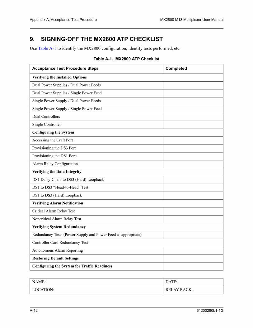
Appendix A, Acceptance Test Procedure MX2800 M13 Multiplexer User Manual
9. SIGNING-OFF THE MX2800 ATP CHECKLISTUse Table A-1 to identify the MX2800 configuration, identify tests performed, etc.
Table A-1. MX2800 ATP Checklist
Acceptance Test Procedure Steps Completed
Verifying the Installed Options
Dual Power Supplies / Dual Power Feeds
Dual Power Supplies / Single Power Feed
Single Power Supply / Dual Power Feeds
Single Power Supply / Single Power Feed
Dual Controllers
Single Controller
Configuring the System
Accessing the Craft Port
Provisioning the DS3 Port
Provisioning the DS1 Ports
Alarm Relay Configuration
Verifying the Data Integrity
DS1 Daisy-Chain to DS3 (Hard) Loopback
DS1 to DS3 “Head-to-Head” Test
DS1 to DS3 (Hard) Loopback
Verifying Alarm Notification
Critical Alarm Relay Test
Noncritical Alarm Relay Test
Verifying System Redundancy
Redundancy Tests (Power Supply and Power Feed as appropriate)
Controller Card Redundancy Test
Autonomous Alarm Reporting
Restoring Default Settings
Configuring the System for Traffic Readiness
NAME: DATE:
LOCATION: RELAY RACK:
A-12 61200290L1-1G

APPENDIX B, PINOUTS
Appendix BPinouts
Table B-1, Table B-2, Table B-3, and Table B-4 list the pin assignments for the connectors located on the MX2800. For more information on these connectors, refer to Section 2, Installation and Operation.
Table B-1. Craft Port Pin Assignments
RJ Pin# DB-9 Function Direction
1 5 GND
2 7 RTS I
3 3 TD I
4 6 DSR O
5 2 RD O
6 8 CTS* O
7 4 DTR I
8 1 DCD O
- 9 not used -
* Used for hardware flow control.
Table B-2. LAN Port Pin Assignments
Pin Name Description
1 TD+ The positive signal for the TD differential pair. This signal contains the serial output data stream transmitted onto the network.
2 TD- The negative signal for the TD differential pair (pins 1 and 2).
3 RD+ The positive signal for the RD differential pair. This signal contains the serial input data stream received from the network.
4, 5 N/A not used
6 RD- The negative signal for the RD differential pair (pins 3 and 6).
7, 8 N/A not used
61200290L1-1G B-1
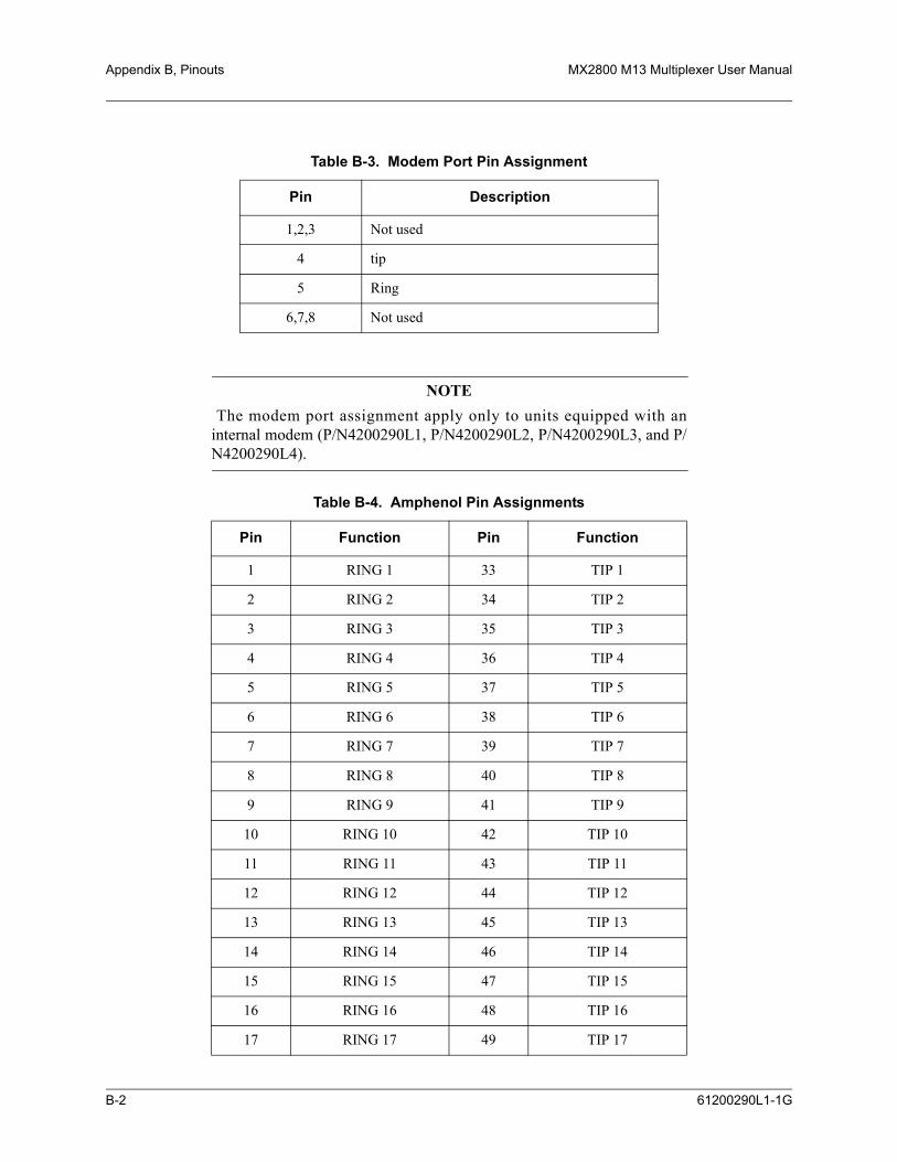
Appendix B, Pinouts MX2800 M13 Multiplexer User Manual
NOTE The modem port assignment apply only to units equipped with aninternal modem (P/N4200290L1, P/N4200290L2, P/N4200290L3, and P/N4200290L4).
Table B-3. Modem Port Pin Assignment
Pin Description
1,2,3 Not used
4 tip
5 Ring
6,7,8 Not used
Table B-4. Amphenol Pin Assignments
Pin Function Pin Function
1 RING 1 33 TIP 1
2 RING 2 34 TIP 2
3 RING 3 35 TIP 3
4 RING 4 36 TIP 4
5 RING 5 37 TIP 5
6 RING 6 38 TIP 6
7 RING 7 39 TIP 7
8 RING 8 40 TIP 8
9 RING 9 41 TIP 9
10 RING 10 42 TIP 10
11 RING 11 43 TIP 11
12 RING 12 44 TIP 12
13 RING 13 45 TIP 13
14 RING 14 46 TIP 14
15 RING 15 47 TIP 15
16 RING 16 48 TIP 16
17 RING 17 49 TIP 17
B-2 61200290L1-1G

MX2800 M13 Multiplexer User Manual Pinouts, Appendix B
NOTETable B-4 applies to both the In and Out DSX1/E1 amphenol connectors.
18 RING 18 50 TIP 18
19 RING 19 51 TIP 19
20 RING 20 52 TIP 20
21 RING 21 53 TIP 21
22 RING 22 54 TIP 22
23 RING 23 55 TIP 23
24 RING 24 56 TIP 24
25 RING 25 57 TIP 25
26 RING 26 58 TIP 26
27 RING 27 59 TIP 27
28 RING 28 60 TIP 28
29 N/A 61 N/A
30 N/A 62 N/A
31 N/A 63 N/A
32 FGND 64 FGND
Table B-4. Amphenol Pin Assignments (Continued)
Pin Function Pin Function
61200290L1-1G B-3

Appendix B, Pinouts MX2800 M13 Multiplexer User Manual
This page is intentionally blank.
B-4 61200290L1-1G

APPENDIX C, SPECIFICATIONS SUMMARY
Appendix CSpecifications Summary
1. INTRODUCTIONThis appendix describes the standard specifications and features incorporated in the MX2800.
2. SPECIFICATIONS AND FEATURESThe specification and features paragraphs are as follows:
• DSX-3 Network Interface
• DSX-1 Interface(s)
• Clocking
• Loopbacks
• Management
• Alarms
• Agency Approvals
• Environment
• Power
• Physical
DSX-3 Network InterfaceChannelized DS3Line length: short (less than 225 ft.) and long (greater than 225 ft.)Framing format: M13 and C-bit parityLine rate: 44.736 MbpsLine interface: dual 75-ohm BNC coax female connectors
DSX-1 Interface(s)Line length: 0-655 feetLine rate: 1.544 MbpsLine code: AMI or B8ZSLine interface(s): two 64-pin amphenol connectors
61200290L1-1G C-1

Appendix C, Specifications Summary MX2800 M13 Multiplexer User Manual
ClockingNetwork: receive from DS3 networkLocal: internally generatedExternal: receive from T1/E1 port or BITS clock from wire-wrap pins on back of chassis
LoopbacksDS3 NetworkANSI T1.107 compatible loopbacksLine loopbacks
DS2 InterfacesDS2 network loopbacks
DSX-1 InterfacesLocal and network loopbacks
ManagementSupported by Total Access Element Management System (JAVA application that provides configuration, performance, network assurance, and provisioning functions). Refer to www.adtran.com website product area for additional information.
Supported by ADVISION (graphical user interface (GUI) SNMP management tool integrated into HP OpenView UNIX platform on SUN Solaris or HP-UX). Refer to www.adtran.com website product area for additional information.
VT100 Terminal InterfaceRJ-48, EIA-232 compatible, female DB-9 adapter provided
Integrated Modem Interface (4200290L1, 4200290L2, 4200290L3, 4200290L4)Dial up access for VT100, SNMP, or TelnetDial out “Cry for help”
SNMP/TelnetIntegrated 10Base-T EthernetMIB II (RFC 1213), RFC 1215, and RFC 1407 compliant.ADTRAN Enterprise MIB for extended monitoring and control/configuration
C-2 61200290L1-1G

MX2800 M13 Multiplexer User Manual Specifications Summary, Appendix C
AlarmsExternal alarm contacts for critical, major, and minor alarmsNormally Open (NO) and Normally Closed (NC) pinoutFront panel alarm cutoff switch
Agency ApprovalsFCC Part 15, Class A, Part 68Industry Canada CS03UL and CULNEBS Level 3
EnvironmentOperating: –40°C to +65°C (–40°F to 149°F)Storage: –40°C to +85°C (–40°F to 185°F)Relative Humidity: Up to 95%, nonconducting
PowerAC version: 120VAC, 27W
DC version: –48 VDC, 30 W
DC version: +24VDC, 30 W
PhysicalDimensions: 7.86” D x 17.0” W x 1.7” H Weight: 5.5 lbs. (redundant); 4.5 lbs. (nonredundant)
61200290L1-1G C-3

Appendix C, Specifications Summary MX2800 M13 Multiplexer User Manual
This page is intentionally blank.
C-4 61200290L1-1G

APPENDIX D, ACRONYMS/ABBREVIATIONS
Appendix DAcronyms/Abbreviations
AACO ............................. alarm cut offACT.............................. activeAIS................................ alarm indication signalALM............................. alarmAMI .............................. alternate mark inversionAmp.............................. amphenolANSI............................. American National Standards Instituteasync............................. asynchronous
BBERT............................ bit error rate testbps ................................ bits per secondBPV .............................. bipolar violation
CCA................................. communications equipment availableCAIS............................. carrier side alarm indication signalCCITT.......................... Consultive Committee for International Telephony and TelegraphyCCV.............................. C-bit coding violationCD................................. carrier detectCES............................... C-bit errored secondsCO ................................ central officeCPE .............................. customer premise equipmentCRC.............................. cyclic redundancy checkCS ................................. clear to sendCSES ............................ C-bit severely errored secondsCSU .............................. channel service unitCTS............................... clear to send
61200290L1-1G D-1

Appendix D, Acronyms/Abbreviations MX2800 M13 Multiplexer User Manual
CV................................. coding violation
DdB ................................. decibelDBU.............................. dial backupDCD.............................. data carrier detectDCE.............................. data communications equipmentDDS .............................. digital data serviceDLCI ............................ data link connection identifierDS1 ............................... digital signal Level 1DS3 ............................... digital signal Level 3DSR .............................. data set readyDSU .............................. data service unitDSX-1........................... digital signal cross connect, Level 1DTE .............................. data terminal equipmentDTR.............................. data terminal ready
EES ................................. errored secondsEq ................................. equipmentEqpt.............................. equipmentEXZ .............................. excessive zeros
FFBE............................... F-bit errorsFCC .............................. Federal Communications CommissionFDL .............................. facility datalinkFEAC ........................... far-end alarm and controlFEBE............................ far-end block error
HHSSI ............................. high-speed serial interface
IIP .................................. internet protocol
KKA ................................ keep alive
D-2 61200290L1-1G
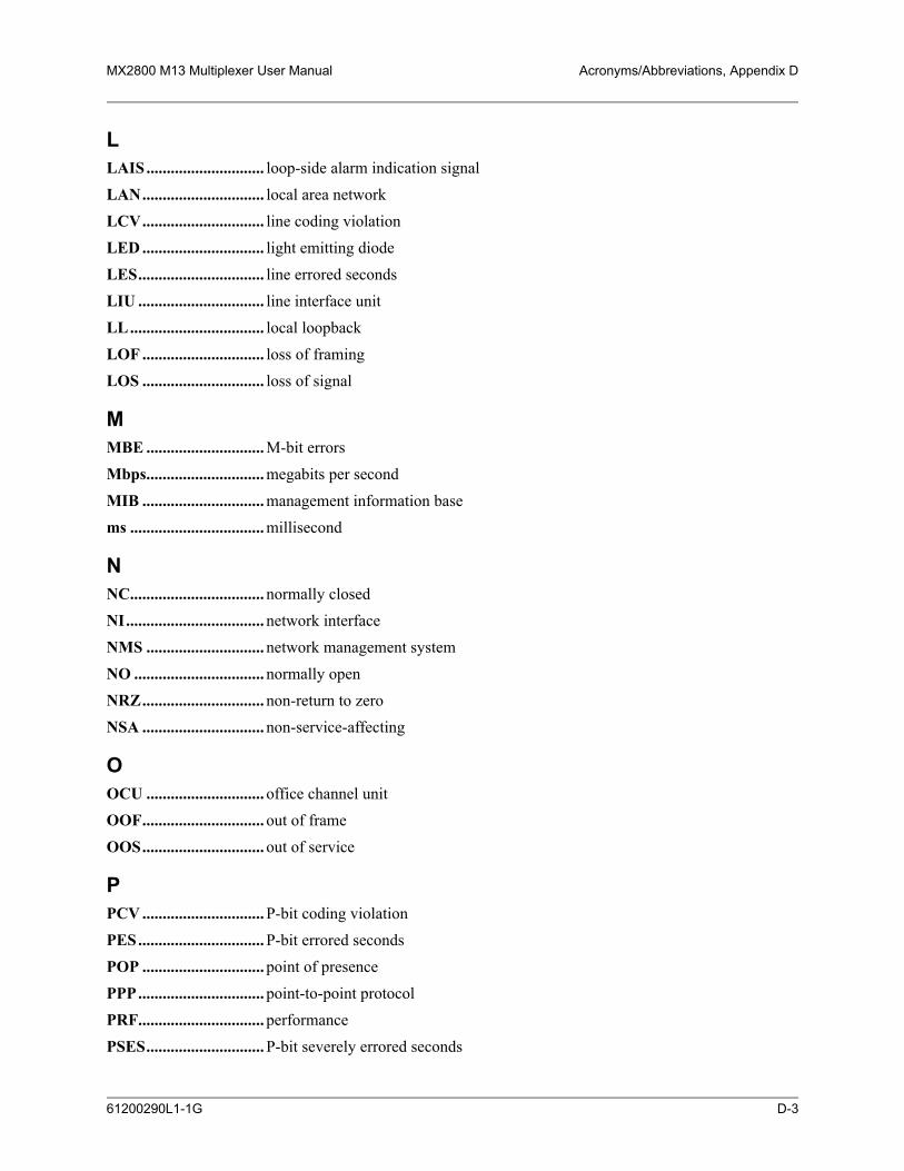
MX2800 M13 Multiplexer User Manual Acronyms/Abbreviations, Appendix D
LLAIS............................. loop-side alarm indication signalLAN.............................. local area networkLCV.............................. line coding violationLED .............................. light emitting diodeLES............................... line errored secondsLIU ............................... line interface unitLL................................. local loopbackLOF .............................. loss of framingLOS .............................. loss of signal
MMBE ............................. M-bit errorsMbps............................. megabits per second
MIB .............................. management information basems ................................. millisecond
NNC................................. normally closedNI.................................. network interfaceNMS ............................. network management systemNO ................................ normally openNRZ.............................. non-return to zeroNSA .............................. non-service-affecting
OOCU ............................. office channel unitOOF.............................. out of frameOOS.............................. out of service
PPCV .............................. P-bit coding violationPES............................... P-bit errored secondsPOP .............................. point of presencePPP............................... point-to-point protocolPRF............................... performancePSES............................. P-bit severely errored seconds
61200290L1-1G D-3

Appendix D, Acronyms/Abbreviations MX2800 M13 Multiplexer User Manual
PSTN ............................ public switched telephone networkPVC .............................. permanent virtual circuit
RRD................................. receive dataRDL.............................. remote digital loopbackRL................................. remote loopbackRMA............................. return material authorizationRS ................................. request to sendRTS............................... request to sendRx ................................. receive
SSA ................................. service affectingSEFS............................. severely errored framing secondsSES ............................... severely errored secondsSLIP ............................. serial line internet protocolSNMP........................... simple network management protocolSONET......................... synchronous optical networkSR ................................. data set readySW56 ............................ switched 56sync............................... synchronous
TTA ................................. terminal equipment availableTD................................. transmit dataTDM............................. time division multiplexingTM................................ test modeTR................................. data terminal readyTx.................................. transmit
UUAS .............................. unavailable seconds
WWAN............................. wide area network
D-4 61200290L1-1G

MX2800 M13 Multiplexer User Manual Acronyms/Abbreviations, Appendix D
XXCV.............................. excessive coding violations
61200290L1-1G D-5

Appendix D, Acronyms/Abbreviations MX2800 M13 Multiplexer User Manual
This page is intentionally blank.
D-6 61200290L1-1G

APPENDIX E, GLOSSARY
Appendix EGlossary
10Base-T Ethernet connector which implements the IEEE standard on 24-gauge, unshielded twisted-pair wiring.
AAMI Alternate Mark Inversion. A bipolar line-coding format in T1 transmission
systems whereby successive ones are alternately inverted.
ANSI American National Standards Institute. A nonprofit organization that coordinates voluntary standards activities in the United States.
asynchronous A method of data transmission which allows characters to be sent at irregular intervals by preceding each character with a start bit followed by a stop bit.
Bbandwidth The bandwidth determines the rate at which information can be sent through a
channel (the greater the bandwidth, the more information that can be sent in a given amount of time).
baud rate A measure of transmission speed over an analog phone line. Baud rate measures the shortest signaling elements per second in the analog signal that a modem sends over an analog phone line. Does not necessarily equal the bit rate.
BERT Bit error rate test. A test that uses any of a number of stress patterns to test T3, T1, FT1, and DDS circuits.
bipolar A signal containing both positive and negative amplitude components.
bipolar violation See BPV.
bit A binary digit representing a signal, wave, or state as either a one or a zero. A bit is the smallest unit of information a computer can process.
bit error The receipt of an encoded bit that differs from what was sent by the transmitter.
bit rate The speed at which bits are transmitted, usually expressed in bits per second (bps).
bps Bits per second. The number of bits passing a specific point per second. Examples of common rates are kbps (one thousand bits per second) and Mbps (one million bits per second). T3 operates at 44.736 Mbps.
61200290L1-1G E-1

Appendix E, Glossary MX2800 M13 Multiplexer User Manual
BPV Bipolar violation. A violation in the alternate mark inversion (AMI) line code in which consecutive 1s are represented by pulses of opposite polarity. BPVs that are not intentional (B8ZS) are counted as errors. Could also be the presence of two consecutive 1 bits of the same polarity on the T-carrier line.
bridge A data communications device that connects two or more networks and forwards packets between them.
byte Generally, an 8-bit quantity of information. This term is used mainly in referring to parallel data transfer, semiconductor capacity, and data storage.
Ccarrier The provider of the telecommunication services to the customer site. Carriers can
be local telephone companies, regional telephone companies, or any inter-exchange carrier such as AT&T, Sprint, or MCI.
C-bit An overhead bit in the DS3 string not used for framing, parity, or alarm indication.
CCITT Consultive Committee for International Telephony and Telegraphy. A standards organization that devises and proposes recommendations for international communications. See also ANSI.
CD Carrier detect. A signal generated by a modem or DSU/CSU indicating the presence of a carrier signal on a communications link.
channel A transmission path between two or more termination points, also called a circuit, facility, line, link, or path.
channel bank Equipment in a telephone central office or customer premises that performs multi-plexing of lower-speed digital channels into a higher-speed composite channel. The channel bank also detects and transmits signaling information for each channel, thereby transmitting framing information so that time slots allocated to each channel can be identified by the receiver.
channel service unit See CSU.
clocking An oscillator-generated signal that provides a timing reference for a transmission link. A clock provides signals used in a transmission system to control the timing of certain functions. The clock has two functions: (1) to generate periodic signals for synchronization, and (2) to provide a time base.
CPE Customer premises equipment. All telecommunications terminal equipment located on the customer premises, including telephone sets, private branch exchanges (PBXs), data terminals, and customer-owned, coin-operated telephones.
E-2 61200290L1-1G
MX2800 M13 Multiplexer User Manual Glossary, Appendix E
craft port The data communications interface between the MX2800 and the control termi-nal. The control terminal is used to communicate commands to the unit.
CSU Channel service unit. A device used to connect a digital phone line coming in from the phone company to either a multiplexer, channel bank, or directly to another device producing a digital signal; for example, a digital PBX, a PC, or data communications device. A CSU performs certain line-conditioning and equalization functions and responds to loopback commands sent from the central office. A CSU also regenerates digital signals. It monitors them for problems and provides a means of testing the digital circuit.
CTS Clear to send. A signal on the DTE interface indicating that the DCE is clear to send data.
Ddata communications equipment See DCE.
data service unit See DSU.
dB Decibel. A unit of measure of signal strength, usually the relation between a trans-mitted signal and a standard signal source.
DCE Data communications equipment. Device that provides all the functions required for connection to telephone company lines and for converting signals between telephone lines and DTE. Also see DTE.
DDS Digital data service. A private line digital service for transmitting data end-to-end at speeds of 2.4, 4.8, 9.6, and 56 kbps (and, in some cases, 19.2, 38.4, or 64 kbps). The systems can use central hub offices for obtaining test access, bridging legs of multi-point circuits, and cross connecting equipment. DDS is offered on an inter-LATA (local access and transport area) basis by AT&T and on an intra-LATA basis by the Bell operating companies.
delay The amount of time by which a signal is delayed. A round-trip transmission delay measurement helps detect possible causes of protocol timeouts.
DLCI Datalink communications identifier. A unique number assigned to a PVC endpoint in a frame relay network. Identifies a particular PVC endpoint within a user's access channel in a frame relay network and has local significance only to that channel.
DS1 Digital signal Level 1. Twenty-four DS0 channels make up one DS1. (Total bandwidth is 1.544 Mbps.)
DS3 Digital signal Level 3. Equivalent of 28 DS1s and 672 DS0s. (Total bandwidth is 44.736 Mbps.)
61200290L1-1G E-3

Appendix E, Glossary MX2800 M13 Multiplexer User Manual
DSU Data service unit. A device designed to transmit and receive digital data on digital transmission facilities.
DTE Data terminal equipment. The end-user terminal or computer that plugs into the termination point (DCE) of a communications circuit. The main difference between the DCE and the DTE is that Pins 2 and 3 are reversed.
EE1 Transmission rates of 2.048 Mbps are available on T1 communication lines. See
also T1.
end device The ultimate source or destination of data flowing through a network (sometimes referred to as DTE).
end user Subscriber who uses (rather than provides) telecommunications services.
ES Errored seconds. A second with one or more coding violations (CVs).
Ethernet Transmission protocol for packet-switching LANs.
Ffacilities The equipment used by carriers to provide communication services.
far end The distant end to that being considered. Not the end where testing is being carried out.
FCC Federal Communications Commission. The U.S. federal agency responsible for regulating interstate and international communications by radio, TV, wire, satel-lite, and cable.
FDL Facility datalink. FDL bits provide overhead communication between the terminal equipment in ESF framing.
Ggateway A device which enables information to be exchanged between two dissimilar
systems or networks.
Hhost computer The primary or controlling computer in a multiple computer operation.
Iidle code In a T3 circuit, an idle code consists of a sequence of 1100 over the entire payload
bandwidth.
in-band Signaling (dialing, loopbacks, management, configuration, etc.) over the same channel used for data.
E-4 61200290L1-1G
MX2800 M13 Multiplexer User Manual Glossary, Appendix E
IP Internet protocol. A protocol which provides for transmitting blocks of data between hosts identified by fixed-length addresses.
LLAN Local area network. A privately owned network that offers high-speed communi-
cations channels to connect information processing equipment in a limited geographic area.
local loopback (LL) A type of test used to verify the operation of the local terminal equipment, the
CSU, and the connection between the two. The signal from the DTE is looped back by the CSU and is sent back to the DTE.
loopback The technique for testing the processing circuitry of a communications device. May be initiated locally or remotely via a telecommunications circuit. Device being tested will echo back received test data. The results are compared with the original data.
LOS Loss of signal. Defined as a line state in which no pulses are received for 175 bit positions.
MM13 DS1/DS3 multiplexer that combines up to 28 DS1 channels into one DS3 channel.
Uses two-stage, bit synchronous TDM.
Mbps Megabits per second (one million bits per second).
MIB Management information base. A database of network management information used by SNMP.
modem Acronym for modulator/demodulator. Equipment that converts digital signals to and from analog signals. Used to send digital signals over analog phone lines.
monitor To watch or listen to a signal non intrusively.
multi-point circuit A single communications circuit that has more than two terminations.
NNC Normally closed. Relay switch contacts that remain closed when inactive.
near end The on-site unit.
NI Network interface. The demarcation point between the CPE and the PSTN.
NO Normally open. Relay switch contacts that remain open when inactive.
61200290L1-1G E-5

Appendix E, Glossary MX2800 M13 Multiplexer User Manual
NRZ Non return to zero. A mode in which the digital level is low for a 0 bit and high for a 1 bit, and does not return to zero between successive 1 bits.
Oout-of-band Signaling that is separated from the channel carrying information (voice, data,
video, etc.). Typically the separation is accomplished by a filter. The signaling includes dialing and other supervisory signals.
Ppoint-to-point Type of communications link that connects a single device to another single
device, such as a remote terminal to a host computer.
POP Point of presence. Physical place within a LATA (local access and transport area) where a long distance carrier or a cellular provider interfaces with the network of the local exchange carrier (LEC). A POP is usually a building serving as the point of termination which houses switches and transmission equipment.
protocol A set of rules controlling the orderly exchange of information between stations in data communications networks or systems.
PSTN Public switched telephone network. Usually refers to the worldwide voice telephone network available for public use.
Rred alarm Unframed all ones signal (keep alive signal). A red alarm is declared on detection
of LOS or OOF not caused by an alarm indication signal (AIS) that persists for more than two seconds.
remote configuration A feature designed into ADTRAN products that allows remote units to be config-
ured from a local unit or a VT100-compatible terminal.
router A device that supports communications between networks. Routers are similar to bridges, except that routers provide more functionality (such as finding the best route between networks and providing network management capabilities).
Sservice The provision of telecommunications to customers by a common carrier, adminis-
tration, or private operating agency using voice, data, and/or video technologies.
service provider A company that delivers or sells a telecom service.
SES Severely errored seconds. A second in which more than 320 code violations (CVs) occurred or an OOF condition occurred.
signaling Communication between switches to set up and terminate calls.
E-6 61200290L1-1G

MX2800 M13 Multiplexer User Manual Glossary, Appendix E
SNMP Simple network management protocol. A control and reporting scheme widely used to manage devices from various vendors. SNMP operates on top of the Inter-net protocol.
SONET Synchronous optical network. A standard format for transporting a wide range of digital telecommunications services over optical fiber. SONET is characterized by standard line rates, optical interfaces, and signal formats.
SR Data set ready. A signal on the DTE interface that indicates if a connection exists and if the devices are ready to start handshaking control signals so communica-tions can begin.
synchronous Communications in which the timing is achieved by sharing a single clock. Each end of the transmission synchronizes itself with the use of clocks and information sent along with the transmitted data.
TT1 Transmission rates of 1.544 Mbps are available on T1 communication lines. Also
referred to as digital signal Level 1 (DS-1). See also E1.
T3 Transmission rates of 44.736 Mbps are available on T3 communication lines. Also referred to as digital signal Level 3 (DS-3).
TDM Time division multiplexing. A technique for transmitting two or more signals at the same time over a single communication medium. This is accomplished by allocating channels to the bandwidth for specific increments of time.
Telnet The standard TCP/IP remote login protocol specified in RFC-854.
transceiver A combination of transmitter and receiver, providing both output and input inter-faces within a single device.
transmission The signaling of data over telecommunications channels.
VV.35 A standard for trunk interface between a network access device and a packet
network that defines signaling for data rates greater than 19.2 kbps.
VT100 A non intelligent terminal or terminal emulation mode used for asynchronous communications. Used to configure the MX2800.
WWAN Wide area network. A communications network serving geographically separate
areas. A WAN typically extends a LAN outside the building to link to other LANs over telephone lines.
61200290L1-1G E-7

Appendix E, Glossary MX2800 M13 Multiplexer User Manual
Yyellow alarm A T3 yellow alarm is an indication sent back toward the source of a failed transmit
circuit in a DS3 two-way transmission path. The X-bits (X1 and X2) are set to zero.
E-8 61200290L1-1G

APPENDIX F, WARRANTY
Appendix FWarranty
1. WARRANTY AND CUSTOMER SERVICEADTRAN will replace or repair this product within the warranty period if it does not meet its published specifications or fails while in service. Warranty information can be found at www.adtran.com/warranty.
Refer to the following subsections for sales, support, Customer and Product Service (CAPS) requests, or further information.
2. ADTRAN SALESPricing/Availability:800-827-0807
3. ADTRAN TECHNICAL SUPPORTPre-Sales Applications/Post-Sales Technical Assistance:800-726-8663
Standard hours: Monday - Friday, 7 a.m. - 7 p.m. CSTEmergency hours: 7 days/week, 24 hours/day
4. ADTRAN REPAIR/CAPSReturn for Repair/Upgrade:(256) 963-8722
5. REPAIR AND RETURN ADDRESSContact CAPS prior to returning equipment to ADTRAN.
ADTRAN, Inc.CAPS Department901 Explorer BoulevardHuntsville, Alabama 35806-2807
61200290L1-1G F-1

Appendix F, Warranty MX2800 M13 Multiplexer User Manual
This page is intentionally blank.
F-2 61200290L1-1G
INDEX
Index
Numerics24 Hour Alarm History
DS2 Statistics menu 5-9DS3 Statistics menu 5-2
Aacknowledgment messages
All Right 9-3In Progress 9-3
ACT LED, active cards 2-16ACT LED, standby cards 2-17Active Controller menu 3-6Active state, Card A/Card B 4-5agent, SNMP 1-3AIS
24 Hour Alarm History (DS3 statistics) 5-2Remote status 4-3State, DS2 4-6State, DS3 4-2
AIS Carrier Alarms 5-13AIS Loop Alarms 5-13alarm events 9-11Alarm Log 5-14Alarm menu
DS3 State 4-2System State 4-4
alarmssystem 3-34
ALM LED, active cards 2-16ALM LED, standby cards 2-17Analog Loopback, remote all T1/E1 6-8Analog Network loopback test 6-3Answer on Ring menu 3-20Auto Save menu 3-38autonomous messages 9-4, 9-11Bbackup protection
non-redundant power mode 8-1power supply and source recovery mode 8-2power supply recovery mode 8-2
battery backup, overview 1-4
61200290L1-1G
Battery Low, Power Supply State 4-4baud rate, setting 3-20BERT
CSU Loopback w/ 6-4Line 6-5
Bipolar Violations 5-13blue alarm
DS2 State 4-6network state 4-2Remote status 4-3
breakout paneloverview 1-3
CCAIS
T1/E1 State 4-6Card A/Card B
Active state 4-5Failure 4-5Not Installed 4-5Stand By 4-5
Card A/Card B menu 4-5Card Comm menu 4-5Card Failure
System State Alarm 4-4C-Bit Coding Violations (CCV) 5-8C-Bit Errored Seconds (CES) 5-8C-bit parity
remote loopback 6-4C-Bit Severely Errored Seconds (CSES) 5-8Charger Fail, Power Supply State 4-4circuit protection mode 4-5Clear All Local DS3 Statistics 5-9Clear All T1/E1 Alarm Counts 5-13clearing statistics 5-9codec line/net loopback 6-4Common Eqpt Fail (NSA) Remote status 4-3Configuration menus
Network Interface 3-4Save Configuration 3-44Utilities 3-38
Connection Timeout menu 3-20
I-1

Index MX2800 M13 Multiplexer User Manual
Controller Traps 3-22craft port pin assignments B-1CSU Loopback 6-4CSU Loopback w/BERT 6-4Ddata link state 4-2data mode 6-9Date & Time menu 3-33date, setting 3-33Dial String menu 3-19Dialout On Trap menu 3-20digital line/net loopback 6-3digital loopback 6-7DS1 Eqpt Fail (NSA) 4-3DS1 Eqpt Fail (SA), Remote status 4-3DS2 Configuration menu 3-7DS2 State
AIS 4-6LOF 4-6OK 4-6RAI 4-6
DS2 Statistics menu 5-9DS3 Configuration menu 3-4DS3 Eqpt Fail (NSA) 4-3DS3 Eqpt Fail (SA) 4-3DS3 Loopbacks 6-6DS3 State
Alarm 4-2In Test 4-2Normal 4-2
DS3 State menu 4-1DS3 Statistics menu 5-2DSX-1/E1 interfaces, rear panel 2-8DSX-3 interfaces, rear panel 2-7EEquipment Code menu 3-37error codes 9-17Error, Power Supply State 4-4establishing a terminal connection 2-9Excessive CV, State 4-2Excessive Switches, System State Alarm 4-4FFacility ID menu 3-36Failure, Card A/Card B 4-5fan faceplate, overview 1-4Far End Block Errors (FEBE) 5-9F-Bit Errors (FBE) 5-8
I-2
FEAC 6-4Frame ID menu 3-36GGateway IP Address menu 3-17HHangup menu 3-21Host Facility menu 3-37Host IP Address menu 3-37HOT, T1/E1 State 4-6IIdle
24 Hour Alarm History (DS3 statistics) 5-3Remote status 4-3State 4-2
Idle Timeout menu 3-19In Test, DS3 State 4-2informational events 9-11Initializing String menu 3-19Interval starting at:, Performance Parameters (DS3)
5-7IP address trap 3-21IP Hosts menu 3-33IP Security menu 3-33LLAIS
T1/E1 State 4-6LAN pin assignments B-1LAN port, MX2800 2-7Last Modem Response menu 3-21LEDs
ACT, active cards 2-16ACT, standby cards 2-17ALM, active cards 2-16ALM, standby cards 2-17NET, active cards 2-16NET, standby cards 2-17PRF, active cards 2-16PRF, standby cards 2-17
Line BERT 6-5Line Coding menus, T1/E1 3-10Line Coding Violation (LCV) 5-8Line Coding Violations (LCV) 5-8Line Errored Seconds (LES) 5-8Line Length menu
long 3-4short 3-4
Line Length menus, T1/E1 3-11
61200290L1-1G

MX2800 M13 Multiplexer User Manual Index
Line Loopback 6-7Local IP Address menu 3-17Location ID menu 3-36LOF
24 Hour Alarm History (DS3 statistics) 5-2DS2 State 4-6State 4-2
logging out 2-15long line length 3-4loopback
CSU 6-4CSU with BERT 6-4DS2 6-9DS3 6-6T1/E1 6-2
Loopback menuAnalog Network 6-3Codec Line/Net 6-4CSU Loopback 6-4CSU Loopback w/BERT 6-4Digital Line/Net 6-3Digital Loopback 6-7DS2 Loopback 6-9DS2 Network 6-9DS3 Loopbacks 6-6Line BERT 6-5Line Loopback 6-7Metallic Loopback 6-8Remote all T1/E1 6-8Remote Loopback 6-4, 6-8T1/E1 Loopbacks 6-2Tributary 6-2
Loopback menu, network configuration 3-7LOS
24 Hour Alarm History (DS3 statistics) 5-2Remote status 4-3State 4-2T1/E1 State 4-6
Loss of Signal Alarms 5-13Mmanagement station addresses 3-33Maximum Redial Attempts menu 3-19menu navigation 2-10metallic loopback 6-8MIB, SNMP 1-3Miscellaneous menu 3-33Miscellaneous menus, network configuration 3-7Modem Mode menu 3-20
61200290L1-1G
Modem port, MX2800 2-7Multiple DS1 LOS, Remote status 4-3MX2800 options 1-3MX2800 Product Overview 1-1Nnavigating the menus 2-10NET LED, active cards 2-16NET LED, standby cards 2-17Network Interface menus 3-4network manager, SNMP 1-2network protection mode 4-5none, Protection mode 4-5non-redundant power mode 8-1Normal
Power Supply State 4-4Remote status 4-3
Not Installed, Card A/Card B 4-5OOK
DS2 State 4-6T1/E1 state 4-6
OOFRemote status 4-3
options for the MX2800 1-3output response messages 9-4PPause Between Calls menu 3-20P-Bit Coding Violations (PCV) 5-8P-Bit Errored Seconds (CES) 5-8P-Bit Severely Errored Seconds (CSES) 5-8Performance Parameters (DS3)
C-Bit Coding Violations (CCV) 5-8C-Bit Errored Seconds (CES) 5-8C-Bit Severely Errored Seconds (CSES) 5-8Clear All Local DS3 Statistics 5-9Far End Block Errors (FEBE) 5-9F-Bit Errors (FBE) 5-8Interval starting at: 5-7Line Coding Violation (LCV) 5-8Line Coding Violations (LCV) 5-8Line Errored Seconds (LES) 5-8P-Bit Coding Violations (PCV) 5-8P-Bit Errored Seconds (CES) 5-8P-Bit Severely Errored Seconds (CSES) 5-8Refresh All Remote Statistics 5-9Severely Errored Framing Seconds (SEFS) 5-8Unavailable Seconds (UAS) 5-8
I-3

Index MX2800 M13 Multiplexer User Manual
Performance Parameters menu (DS2) 5-11Performance Parameters menu (DS3) 5-4phone numbers
primary 3-19secondary 3-19
pin assignmentsauxiliary port B-1control connector B-1craft port B-1LAN B-1LAN port B-1
pinouts A-1, B-1power connection, rear panel 2-8Power Fail, Power Supply State 4-4power loss recovery
non-redundant power mode 8-1power supply and source recovery mode 8-2power supply recovery mode 8-2
Power LowPower Supply State 4-4
power supply and source recovery mode 8-2power supply recovery mode 8-2Power Supply State
Battery Low 4-4Charger Fail 4-4Error 4-4Normal 4-4Power Fail 4-4Power Low 4-4Temp Critical 4-4Temp High 4-4
Power Supply State menu 4-4power up
AC version 2-2DC version 2-2
PRF LED, active cards 2-16PRF LED, standby cards 2-17Privilege Level 2-15Protection Configuration menus 3-6Protection menu 4-5protection mode
Circuit 4-5circuit failure recovery 7-2, 7-3Network 4-5network failure recovery 7-3None 4-5non-redundant 7-1
Protection Threshold 3-14
I-4
RRAI
24 Hour Alarm History (DS3 statistics) 5-2DS2 State 4-6Remote status 4-3State 4-2
Read Community Name 3-24Read Community Name address 3-21receiving inspection 2-1redundancy
circuit and network failure recovery mode 7-3circuit failure recovery mode 7-2non-redundant mode 7-1
Refresh All Remote Statistics 5-9refreshing remote statistics 5-9remote loopback
DS3 6-8T1/E1 6-4
Remote Loopbacks menu 3-5Remote menu 4-3Remote state
unknown 4-3Remote status
AIS 4-3Common Eqpt Fail (NSA) 4-3DS1 Eqpt Fail (NSA) 4-3DS1 Eqpt Fail (SA) 4-3DS3 Eqpt Fail (NSA) 4-3DS3 Eqpt Fail (SA) 4-3Idle 4-3LOF 4-3LOS 4-3Multiple DS1 LOS 4-3Normal 4-3RAI 4-3Single DS1 LOS 4-3
resetting the system 3-43Rx Framing menu 4-1SSave Configuration and Alarm Log menu 3-44setting the baud rate 3-20setting the date 3-33setting the time 3-33Severely Errored Framing Seconds (SEFS) 5-8Severity Level menu 3-37shipping, contents 2-1short line length 3-4Single DS1 LOS, Remote status 4-3
61200290L1-1G

MX2800 M13 Multiplexer User Manual Index
SNMP Management Options 3-21SNMP State 3-21SNMP State menu 3-21SNMP, overview 1-2specifications, MX2800 C-1Stand By, Card A/Card B 4-5State menu (DS3 State) 4-2State menus, T1/E1 3-9Statistics menu
24 Hour Alarm History (DS2) 5-924 Hour Alarm History (DS3) 5-2Clear All T1/E1 Alarm Counts 5-13DS2 Statistics 5-9DS3 Statistics 5-2Performance Parameters (DS3) 5-4T1/E1 Statistics 5-13
Statistics menus 5-1Status menu
Alarm (DS3 State) 4-2Alarm (System State) 4-4Card A/Card B 4-5Card Comm 4-5DS2 State 4-6DS3 State 4-1Power Supply State 4-4Protection 4-5Remote 4-3Rx Framing 4-1State 4-2System State 4-4
Subnet Mask menu 3-17Supply Failure, System State Alarm 4-4Switched, System State Alarm 4-4Syslog Setup menu 3-37system alarms 3-34System Name 3-25system reset 3-43System Security 3-26System Security menu 3-26System State Alarm
Card Failure 4-4Excessive Switches 4-4Supply Failure 4-4Switched 4-4
System State menu 4-4TT1/E1 Line Length menu 3-11
61200290L1-1G
T1/E1 menusLine Coding 3-10State 3-9
T1/E1 StateCAIS 4-6HOT 4-6LAIS 4-6LOS 4-6OK 4-6TST 4-6XCV 4-6
T1/E1 Statistics menu 5-13Telnet, overview 1-3Temp Critical, Power Supply State 4-4Temp High, Power Supply State 4-4terminal connection, establishing 2-9time, setting 3-33TL1
alarm events 9-11autonomous messages 9-11commands 9-5Editing 9-17error codes 9-17informational events 9-11messages 9-3responses 9-3
TLOS, State 4-2Transmission menu 3-37Trap Community Name 3-25Trap Generation menu 3-21Trap IP Addresses menu 3-21traps
controller 3-22for calls between primary and secondary num-
bers 3-19for redialing 3-19
Tributary loopback 6-2TST, T1/E1 State 4-6UUnavailable Seconds (UAS) 5-8Unit ID Code menu 3-36Unknown, Remote state 4-3Utilities menu 3-38Vviewing statistical information 5-1WWrite Community Name 3-25
I-5

Index MX2800 M13 Multiplexer User Manual
XXCV
T1/E1 State 4-6
I-6
61200290L1-1G
Notes

®®