Multi-Fragment Effects on the GPU using the -Buffercsilva/papers/i3d2007.pdf · Figure 1: Example...
8
Multi-Fragment Effects on the GPU using the k-Buffer Louis Bavoil * Steven P. Callahan * Aaron Lefohn † Jo˜ ao L. D. Comba ‡ Cl´ audio T. Silva * * Scientific Computing and Imaging Institute, University of Utah † Neoptica ‡ Instituto de Inform´ atica, UFRGS Figure 1: Example effects using the k-buffer for multi-fragment processing. The Lucy model (28,055,742 triangles) is rendered with trans- parency on the left and with translucency on the right. These effects captured 8 fragments per pixel in a single geometry pass and were rendered with a current hardware implementation that avoids read-modify-write hazards. With our proposed extension to hardware, these hazards can be automatically avoided and performance improved. Abstract Many interactive rendering algorithms require operations on mul- tiple fragments (i.e., ray intersections) at the same pixel loca- tion; however, current Graphics Processing Units (GPUs) capture only a single fragment per pixel. Example effects include trans- parency, translucency, constructive solid geometry, depth-of-field, direct volume rendering, and isosurface visualization. With current GPUs, programmers implement these effects using multiple passes over the scene geometry, often substantially limiting performance. This paper introduces a generalization of the Z-buffer, called the k-buffer, that makes it possible to efficiently implement such algo- rithms with only a single geometry pass, yet requires only a small, fixed amount of additional memory. The k-buffer uses framebuffer memory as a read-modify-write (RMW) pool of k entries whose use is programmatically defined by a small k-buffer program. We present two proposals for adding k-buffer support to future GPUs and demonstrate numerous multiple-fragment, single-pass graph- ics algorithms running on both a software-simulated k-buffer and a k-buffer implemented with current GPUs. The goal of this work is to demonstrate the large number of graphics algorithms that the k-buffer enables and that the efficiency is superior to current multi- pass approaches. Keywords: fragment processing, graphics hardware, visibility or- dering, blending, volume rendering, transparency, CSG 1 Introduction Raster-based graphics algorithms simulate many effects by operat- ing on multiple fragments in the same pixel. Several existing algo- rithms keep all the fragments for each pixel [Carpenter 1984; Mark and Proudfoot 2001; Wittenbrink 2001] so that they can be sorted and composited in either front-to-back or back-to-front order for transparency. However, the unbounded memory requirements for these types of algorithms is a limiting factor for practical applica- tions. Recent work by Callahan et al. [2005] proposed the k-buffer—a fixed size buffer of fragments per pixel that is maintained in GPU memory. This k-buffer was shown to be effective for sorting and compositing fragments in the special case of direct volume ren- dering with current graphics hardware. However, many applica- tions other than direct volume rendering require access to multiple fragments simultaneously. Here, we generalize the definition of the k-buffer to be a pool of fragments per pixel that can be read, modified, and written at the fragment level. The benefit of the k- buffer is that it allows fragments to be compared, ordered, blended, and discarded in a streaming manner. Thus, many effects that nor- mally require multiple passes over the scene geometry can instead be streamed through the k-buffer in one pass. Note that in this pa- per, we refer to a pass as a rendering pass over the scene geometry, not image processing passes, such as deferred shading, which ren- der a screen-aligned quadrilateral with a pixel shader. For large or complex scenes, the geometry passes are much more expensive than the image processing passes. Whereas a traditional Z-buffer-based framebuffer saves fragment results for a single depth per pixel (the front-most fragment), the k-buffer can save up to k fragments with only a small increase in memory requirements. By giving access to multiple ray intersec- tions along a viewing ray, the additional information in a k-buffer provides algorithms with a more global view of the scene, in turn opening up a number of new algorithmic possibilities for raster graphics. For example, the first k fragments per pixel in front-to- back order can be stored in a k-buffer, effectively performing depth peeling in a single pass. Since the k-buffer supports programmable RMW operations, it can also be used to implement a Z-buffer, a stencil buffer, or arbitrary blending. The k-buffer can be implemented in current hardware using read- modify-write (RMW) operations on textures at the fragment level. Currently, this feature is allowed in hardware, though the results are undefined. Because of the highly parallel nature of fragment processing on the GPU, there is no guarantee that artifacts will not
Transcript of Multi-Fragment Effects on the GPU using the -Buffercsilva/papers/i3d2007.pdf · Figure 1: Example...
Multi-Fragment Effects on the GPU using the k-Buffer
Louis Bavoil∗ Steven P. Callahan∗ Aaron Lefohn† Joao L. D. Comba‡ Claudio T. Silva∗∗ Scientific Computing and Imaging Institute, University of Utah
† Neoptica ‡ Instituto de Informatica, UFRGS
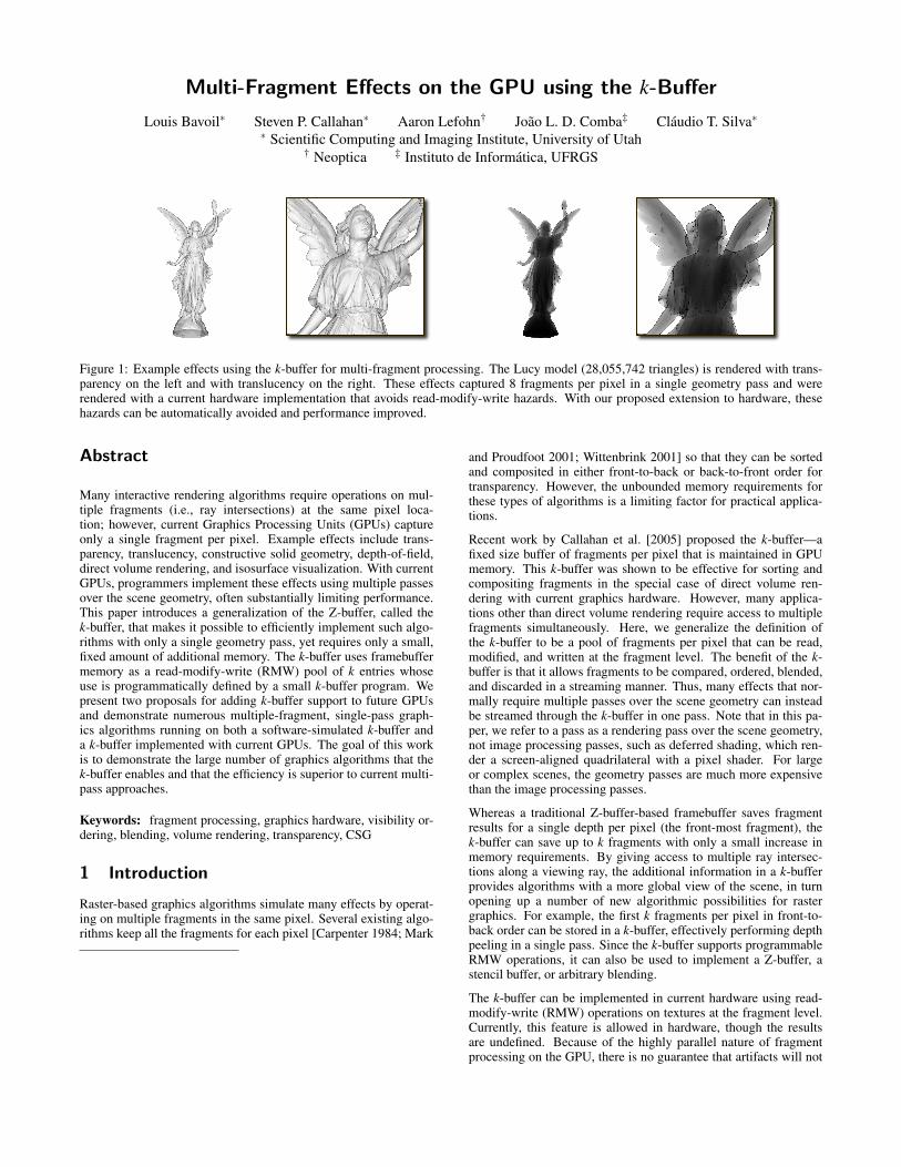
Figure 1: Example effects using the k-buffer for multi-fragment processing. The Lucy model (28,055,742 triangles) is rendered with trans-parency on the left and with translucency on the right. These effects captured 8 fragments per pixel in a single geometry pass and wererendered with a current hardware implementation that avoids read-modify-write hazards. With our proposed extension to hardware, thesehazards can be automatically avoided and performance improved.
Abstract
Many interactive rendering algorithms require operations on mul-tiple fragments (i.e., ray intersections) at the same pixel loca-tion; however, current Graphics Processing Units (GPUs) captureonly a single fragment per pixel. Example effects include trans-parency, translucency, constructive solid geometry, depth-of-field,direct volume rendering, and isosurface visualization. With currentGPUs, programmers implement these effects using multiple passesover the scene geometry, often substantially limiting performance.This paper introduces a generalization of the Z-buffer, called thek-buffer, that makes it possible to efficiently implement such algo-rithms with only a single geometry pass, yet requires only a small,fixed amount of additional memory. The k-buffer uses framebuffermemory as a read-modify-write (RMW) pool of k entries whoseuse is programmatically defined by a small k-buffer program. Wepresent two proposals for adding k-buffer support to future GPUsand demonstrate numerous multiple-fragment, single-pass graph-ics algorithms running on both a software-simulated k-buffer anda k-buffer implemented with current GPUs. The goal of this workis to demonstrate the large number of graphics algorithms that thek-buffer enables and that the efficiency is superior to current multi-pass approaches.
Keywords: fragment processing, graphics hardware, visibility or-dering, blending, volume rendering, transparency, CSG
1 Introduction
Raster-based graphics algorithms simulate many effects by operat-ing on multiple fragments in the same pixel. Several existing algo-rithms keep all the fragments for each pixel [Carpenter 1984; Mark
and Proudfoot 2001; Wittenbrink 2001] so that they can be sortedand composited in either front-to-back or back-to-front order fortransparency. However, the unbounded memory requirements forthese types of algorithms is a limiting factor for practical applica-tions.
Recent work by Callahan et al. [2005] proposed the k-buffer—afixed size buffer of fragments per pixel that is maintained in GPUmemory. This k-buffer was shown to be effective for sorting andcompositing fragments in the special case of direct volume ren-dering with current graphics hardware. However, many applica-tions other than direct volume rendering require access to multiplefragments simultaneously. Here, we generalize the definition ofthe k-buffer to be a pool of fragments per pixel that can be read,modified, and written at the fragment level. The benefit of the k-buffer is that it allows fragments to be compared, ordered, blended,and discarded in a streaming manner. Thus, many effects that nor-mally require multiple passes over the scene geometry can insteadbe streamed through the k-buffer in one pass. Note that in this pa-per, we refer to a pass as a rendering pass over the scene geometry,not image processing passes, such as deferred shading, which ren-der a screen-aligned quadrilateral with a pixel shader. For largeor complex scenes, the geometry passes are much more expensivethan the image processing passes.
Whereas a traditional Z-buffer-based framebuffer saves fragmentresults for a single depth per pixel (the front-most fragment), thek-buffer can save up to k fragments with only a small increase inmemory requirements. By giving access to multiple ray intersec-tions along a viewing ray, the additional information in a k-bufferprovides algorithms with a more global view of the scene, in turnopening up a number of new algorithmic possibilities for rastergraphics. For example, the first k fragments per pixel in front-to-back order can be stored in a k-buffer, effectively performing depthpeeling in a single pass. Since the k-buffer supports programmableRMW operations, it can also be used to implement a Z-buffer, astencil buffer, or arbitrary blending.
The k-buffer can be implemented in current hardware using read-modify-write (RMW) operations on textures at the fragment level.Currently, this feature is allowed in hardware, though the resultsare undefined. Because of the highly parallel nature of fragmentprocessing on the GPU, there is no guarantee that artifacts will not

appear from overlapping geometry in screen space. We addressthis issue by describing solutions that avoid the race conditions thatcan occur with overlapping fragments. This current implementationis used for validating our k-buffer applications, generating images,and producing experimental results of the data structure. However,with a few modifications to the current GPU pipeline, we believethat full k-buffer support is possible. We propose two such modifi-cations that would avoid RMW hazards in future hardware.
We believe that the k-buffer has important implications for interac-tive graphics and visualization because of the number of applica-tions that it enables or simplifies. The contributions of this paperinclude:
• we discuss a general definition of the k-buffer and its imple-mentation in current hardware;
• we suggest modifications to the current hardware pipeline toenable full hardware support of a k-buffer on future GPUs;
• we outline efficient single-pass algorithms using the k-bufferthat normally require expensive, multi-pass algorithms usinga traditional Z-buffer; and
• we provide experimental results of our applications of the k-buffer on current GPUs and compare them to multi-pass ap-proaches.
The rest of the paper is outlined as follows. Section 2 providesan overview of related research. Section 3 describes the generalk-buffer framework including future and current hardware imple-mentations. Section 4 describes specific algorithms for single-passeffects facilitated by the k-buffer. We provide experimental resultsof the k-buffer in Section 5. Finally, we provide a general discus-sion in Section 6 and conclude our paper in Section 7.
2 Related Work
Single-Pass Approaches. There are many relevant publications onstoring and processing multiple fragments per pixel. The traditionalimage-based algorithm for fragment sorting is the Z-buffer [Cat-mull 1974]. It is a streaming algorithm—for every pixel, the frag-ment with lowest (or greatest) depth is kept and the others are dis-carded. The A-buffer [Carpenter 1984] is an extension of the Z-buffer which stores all the fragments rasterized per pixel in a list,which is then sorted according to depth. Fragments that belong tothe same surface and that have very close depth values are merged.This algorithm is not suitable to current graphics hardware becauseof its unbounded memory per pixel. The R-buffer [Wittenbrink2001] is a variation of the A-buffer. All the fragments for the sceneare stored in a single FIFO queue in memory. Although the R-bufferwas designed for hardware implementation, storing a large numberof transparent fragments is not feasible in practice. Another stream-ing approach for fragment processing is the Z3 algorithm [Jouppiand Chang 1999]. Z3 uses a fixed number of fragments per pixeland thus requires less memory than the A-buffer or R-buffer. Whenthe maximum number of fragments per pixel is reached, it selectsthe two closest fragments and merges them together using a set ofheuristics based on pixel coverage. Of these streaming methods,only the Z-buffer has an actual hardware implementation in currentGPUs. Recently, Eisemann and Decoret [2006] showed that an ap-proximate partitioning of the scene can be performed in a singlepass on the GPU by voxelizing the scene. Although this techniqueis very efficient for volumetric effects such as transmittance shadowmapping, it does not allow effects which require the exact locationsof the fragments, such as transparency. Of these algorithms, the k-buffer is most similar to the Z3 architecture because it stores a fixed
number of fragments per pixel. The k-buffer can be seen as a gen-eralization of Z3 where the storage and insertion of the fragmentshas been made programmable.
Multi-Pass Approaches. Due to memory resources on graphicshardware, multi-pass rendering is often required to achieve manyeffects. The F-buffer [Mark and Proudfoot 2001] is very similarto the R-buffer, except that it does not sort the fragments. The F-buffer requires semi-transparent surfaces to be rendered in depth or-der, although it may be possible to sort an F-buffer using a bitonicsort. Implementations of the F-buffer which require rendering thewhole geometry for every pass are available on ATI’s graphics hard-ware [Houston et al. 2005]. The original depth peeling algorithmby Mammen [1984] proposes a solution for sorting fragments bypeeling the layers in depth order in separate passes. A hardwareimplementation was more recently described by Everitt [2001].Depth peeling has been used for rendering order-independent trans-parency [Everitt 2001; Wexler et al. 2005; Luft and Deussen 2006],volume rendering [Nagy and Klein 2003; Bernardon et al. 2006],global illumination [Hachisuka 2005; Mendez et al. 2006], colli-sion detection [Heidelberger et al. 2003], and multi-layer shadowmaps [Woo 1992; Bavoil et al. 2006]. Kelley et al. [1994] proposeda hybrid solution that stores four RGBAZ fragments per pixel,sorted front-to-back, and handles overflow with multiple passes. Ineach pass, the four layers are composited into a single layer andthe three remaining layers are used to capture the next fragments.A recent approach similar to depth peeling is the Vis-Sort algo-rithm [Govindaraju et al. 2005] which sorts 3D primitives using oc-clusion queries on the GPU, assuming there are no visibility cyclesand no intersecting primitives. With Vis-Sort, the number of passesrequired to composite transparent fragments depends on the disor-der in the topological sort of the geometry. The k-buffer simplifiesmulti-pass approaches by allowing k fragments to be operated onin a single pass. Since it operates in image-space, it also avoidsproblems with visibility cycles and intersecting primitives.
3 The k-Buffer
The k-buffer is a generalization of the traditional Z-buffer-basedframebuffer. Instead of restricting framebuffers to a single depthvalue, a single stencil value, and n color values, the k-buffer usesframebuffer memory as a RMW pool of k entries whose use is pro-grammatically defined by k-buffer operations. In essence, the recentaddition of multiple render targets (MRTs) to GPUs already allowsmultiple fragments to be stored, albeit in textures. We take thisa step further and suggest that the programmable combination ofthese fragments is as important as their storage to achieve many ad-vanced effects in a single pass. The general structure of the k-bufferalgorithms for each fragment f that is rasterized is as follows:
1. Read the k-buffer elements for this pixel from memory. Thesevalues, along with the incoming fragment f , are now availablefor processing.
2. Modify the k-buffer elements using f .
3. Write the k-buffer elements back to memory and discard f .
Many effects can be performed using different types of modify op-erations on the k-buffer values. Generally, these modify operationsfall into two types. The first type is to use the k-buffer to accumu-late up to k fragments for a post-processing pass such as deferredshading. Examples of this type of algorithm are depth peeling anddepth partitioning, which can be used to perform effects such astransparency, translucency, midpoint shadow mapping, constructivesolid geometry, and depth-of-field. The second type is to use the k-buffer as a fragment stream processor and programmable blender.An example of this type of algorithm is fragment ordering, which

can be used to perform isosurfacing, direct volume rendering, andtransparency of geometry with large depth complexity.
The first type of algorithm generally requires a fixed number offragments to perform the desired effect. The k-buffer is used astemporary storage of the most significant fragments to be used ina post-processing pass. These fragments can be rasterized in anyparticular order with no change in the final result. However, thesecond type of algorithm generally needs to consider all fragmentsto achieve the desired effect. In this case, when a new fragmentis inserted, a blending operation is performed and a fragment isdiscarded. Thus, the rasterization order of the fragments will af-fect the output. The k-buffer is capable of sorting a k-nearly sortedsequence (k-NSS) of fragments. Given a sequence S of fragmentdepths, S is a k-NSS if no depth in S is more than k positions outof place. Therefore, when fragment ordering is required, the ge-ometry needs to be rasterized in at least a partial order so that thek-buffer can complete the ordering and blend the results all in onepass (see [Callahan et al. 2005] for a more formal definition of a k-NSS). The partial ordering of the geometry occurs in object-spaceprior to rasterization. The extent of the ordering that is required isdependent both on the depth complexity and the available k size.
3.1 Future Hardware Implementation
Complete k-buffer support in hardware would enable fast single-pass effects without RMW hazards that may occur with our currentimplementation. Although the specifics of hardware implementa-tions are not publicly available, we propose two possible high-levelsolutions based upon available information about the current hard-ware pipeline. In both solutions, we implement the k-buffer as a setof floating-point renderable buffers, and write to these buffers usingMRTs. The main difference between the two solutions is where weexecute the k-buffer operations (read, modify, and write). The firstsolution involves changes at the fragment scheduling stage of thepipeline and the second solution involves changes at the blendingstage of the pipeline. Figure 2 shows a simplified version of theGPU pipeline with annotations that specify the areas that requiremodification for our hardware proposals.
3.1.1 Fragment Scheduling
In this solution, the k-buffer operations are implemented in frag-ment programs, and the reads are performed using the connectionbetween the memory partition and the texture cache. However, thisapproach has issues with RMW hazards because current GPUs pro-cess multiple fragments at the same time per fragment pipeline,with multiple parallel pipelines. When an output of a fragment iscomputed, it is not immediately written to memory, but written toa reorder buffer which reorders the fragments in the order in whichthe primitives have been rasterized. This is necessary for the cor-rectness of RMW raster ops such as blending and stencil buffer.This asynchronous write to memory means that if two overlappingfragments are processed concurrently, and they modify a value ofthe k-buffer for the same pixel, one fragment will read an obsoletevalue, and overwrite the value of the other fragment with an incor-rect value. A solution to this issue—like for CPUs—would be toadd dynamic scheduling of fragments to GPUs to detect and avoidpipeline hazards.
The Unified Render Architecture proposed by ATI in the next-generation GPU architecture [Doggett 2005] aims for better loadbalancing on vertex and fragment shaders by executing them on asingle type of shader unit that are managed by a thread arbiter (orthe fragment dispatcher) . The thread arbiter controls the data beingpassed to the shader units, and finds the best possible way to ensurethat all of the shader units are busy. If the thread arbiter can beconfigured, or even programmed in the future, it would be possible
Figure 2: The pipeline of the GeForce 6/7 showing where our pro-posed modifications will occur. Figure adapted from Kilgariff andFernando [2005].
to divide fragments into non-overlapping groups that are processedby different shader units. Similarly to early-Z culling [Kilgariff andFernando 2005], the hardware could keep a scoreboard [Thornton1964] in the form of a coarse image of what fragments are currentlyin the pipeline. For a given incoming fragment packet (fragmentsare currently packed to perform derivative operations), the score-board would be checked for overlaps with a fragment already in thepipeline. If an overlap is detected, the packet could be inserted ina buffer, and the next packet coming from the rasterizer could betested. An overflow of this temporary buffer would result in a stalluntil a pipeline becomes available.
The main advantage to k-buffer support at the rasterization stageis that it leaves the current pipeline relatively unchanged. Anotheradvantage is that k-buffer programs can use all the features of frag-ment shaders, including texture accesses (e.g., for lookup tables).Note that the k-buffer access does not need to be a texture access.It may be more efficient to implement it as varying arguments liketexture coordinates. In any case, k-buffer programs could mix tex-ture accesses with k-buffer accesses. However, there are severaldisadvantages to this proposed solution. First, by modifying depthin fragment programs, early-Z tests are invalidated. Since the k-buffer generally requires all the fragments anyway, this is not amajor issue. Second, the fragment scheduler may adversely affectperformance by reducing the parallelism during fragment process-ing. Finally, full-screen antialiasing presents some challenges be-cause fragment shaders operate on pixel fragments while multisam-ple antialiased blending operations occur on multiple samples perpixel [Blythe 2006]. To support antialiasing with the k-buffer wouldlikely require supporting the more costly supersample antialiasingrather than the more efficient multisample antialiasing.
3.1.2 Programmable Blending
A more promising approach is to implement the k-buffer by allow-ing programmable blending. Currently, the only RMW operationson colors in the graphics pipeline are fixed-function per-pixel op-erations. The k-buffer can be supported by extending RMW capa-bilities using blending programs similar to fragment or vertex pro-grams. Specifying different k-buffer applications could then occur

(a) (b)
Figure 3: Artifacts that appear in our current implementation due tohazards. (a) With the original mesh layout. (b) Sorting the triangleswith a depth sort by centroid.
with the use of a programmable blender that takes as input the re-sults of the fragment shader and outputs the values in the k-bufferfor the pixel. Programmable blending has been discussed as a pos-sible hardware extension in the future [Blythe 2006].
To demonstrate that this model conceptually fits into the currentpipeline, we extended Mesa 6.5 with k-buffer support for pro-grammable blending. We modified the OSMesa driver, which is apurely software implementation of Mesa. The following changesto the existing pipeline were made. In the software rasterizer,we added a k-buffer mode which changes the behavior of MRTs.When in this mode, fragments leaving the fragment program arepassed to a programmable blender. A programmable blender isa specialized fragment program which takes as input the currentpixel in the framebuffer, and the current k-buffer fragments for thispixel, passing these fragments as 4-float varying arguments. Pro-grammable blenders are written in ARBfp1 assembly and speci-fied using a new target GL KBUFFER PROGRAM MESA in place of the usualGL FRAGMENT PROGRAM ARB. This k-buffer program is then optionallyexecuted instead of blending. Figure 10c was rendered using thisimplementation.
Implementing k-buffers with programmable blending has a numberof benefits over implementing them in the fragment program stage.First, it does not require texture (random) memory access, whichmeans the only memory reads are pure stream accesses from theincoming fragment and the k-buffer. Second, it does not requirescheduling so it would not affect the parallelization of the fragmentpipeline. Third, current caching strategies for pixel tiles are crit-ical to GPU performance [Hasselgren and Akenine-Moller 2006]and would still be applicable. Fourth, no cache coherency wouldbe required between the pixel tile caches and the texture caches.Finally, multisample antialiasing would still be possible, given thatthe k-buffer operates directly on subsamples rather than fragments.One consideration of this approach is that many compression algo-rithms are hardcoded for the fixed semantics of each component ofthe framebuffer [Hasselgren and Akenine-Moller 2006]. By gener-alizing the framebuffer, the hardware may no longer know whichchunks of memory can be optimized for depth, stencil, color, etc.
3.2 Current Hardware Implementation
We created an experimental implementation of the k-buffer usingcurrent hardware to test k-buffer applications and demonstrate theflexibility of the framework. All of the effects and results shown inthis paper were created using this implementation, unless specifiedotherwise. Our experimental k-buffer is implemented in OpenGLas a set of textures that can be read and written to in fragment pro-grams using MRTs, as described in Section 3.1.1. Since currenthardware does not handle RMW pipeline hazards, artifacts may ap-
(a) (b) (c)
Figure 4: Depth peeling two layers from the dragon dataset. (a)First layer, (b) Second layer, (c) Transparency using 4 layers.
pear. To perform off-screen rendering into the MRTs with OpenGL,we use a Framebuffer Object (FBO), which is a collection of logicalbuffers such as color, depth, or stencil. Currently, up to four colorbuffers can be attached to an FBO and used as MRTs. Algorithmsoperating on the k-buffer are currently implemented as fragmentprograms on FP32 textures with Z-culling disabled.
If the desired application requires streaming with programmableblending, one of the color attachments may act as an off-screenframebuffer, while the other three contain k-buffer entries. Other-wise, all four available color attachments may be used to store thek-buffer entries. These entries can be single values (e.g., depth), orsets of values (e.g., depth, scalar, color) depending on the applica-tion. Thus, the number of values per entry directly effects the sizeof k available for the application. With four MRTs, it is possibleto store up to 16 fragment attributes using RGBA textures. Theprecision of these color attachments is application specific, thus byquantizing the values, it is possible to pack additional k-buffer en-tries into the color attachments. To minimize the number of at-tributes stored with each k-entry, we would ideally only need tostore one depth value per entry. The world-space position can bereconstructed from the depth (either the clip-space depth or the dis-tance to the eye). From the positions, normals can be estimatedusing central differencing so deferred shading can be performed.Using a lookup table, IDs can also be useful to reduce the numberof attributes stored in the k-buffer.
Our experimental k-buffer reads and writes from the same texturesin each fragment operation. This is available in the current OpenGLAPI, even though the results are undefined. In practice, this mayresult in RMW hazards due to the parallel nature of GPU archi-tectures (for example, see Figure 3). To reduce these hazards, wehave developed two heuristics applied to scene geometry prior torasterization to avoid screen-space overlaps. Depending on the ap-plication and scene, these heuristics may be necessary for correctimages using current hardware. Our first heuristic is to sort theprimitives by their centroid depth. This effectively layers the ge-ometry in screen space, which reduces the likelihood of overlap-ping fragments in the pipeline simultaneously. For algorithms thatrequire complete sorting of the fragments, this object-space sortingis already required, thus the hazards are inherently reduced with-out additional penalty. Our second heuristic is to batch trianglesand flush the graphics pipeline after each batch by rendering a full-screen quadrilateral with a GL FALSE color mask. For performancereasons, we use a simple algorithm to create the batches—trianglesare added to the current batch in order, until a maximum batch sizeis reached. Though these heuristics adversely affect performance byreducing the caching on the GPU and stalling the GPU pipelines,they demonstrate the ability to overcome the RMW hazards thatoccur with the current hardware implementation.

Figure 5: Single-pass transparency by depth peeling with 4 layerson a subset of the UNC Powerplant dataset (1,946,000 triangles).All surfaces are semi-transparent with α = 0.5.
4 Applications
Many effects that normally require multiple geometry passes can besimplified using the k-buffer by simply changing the modify portion(step 2) of the k-buffer algorithm. In this section, we detail a few ofthe many possible applications of the k-buffer.
4.1 Depth Peeling Applications
Depth peeling captures multiple depth layers by stripping the vis-ible layers of fragments in multiple peeling passes using Z-buffertests. The k-buffer makes it possible to perform up to k Z-buffertests in a single geometry pass and therefore capture the first k frag-ments along a viewing ray. Effects that use depth peeling includetransparency, translucency, constructive solid geometry, midpointshadow mapping, and volume rendering. A k-buffer can be usedto perform single-pass depth peeling by storing depth-sorted frag-ments (see Figure 4). The depth values of the k-buffer entries areinitialized with the largest possible depth value. Upon rasterization,each fragment is inserted into the k-buffer in increasing depth order.This insertion sort tests the depth of the incoming fragment with thenearest depth in the sorted k-buffer. If the incoming depth is lessthan the nearest depth, it shifts all the elements in the k-buffer, andsets the nearest fragment to be the incoming fragment. Otherwise,the second nearest fragment is tested, and so on.
Transparency. In real-time applications, transparency is usuallysimulated by compositing fragments in depth order, ignoring refrac-tion at material interfaces. A common way to do this is to performdepth peeling to generate fragments in depth order and compos-ite them into the framebuffer using α-blending [Everitt 2001]. Forsimplicity, we use a uniform α , but a non-uniform α can also beused. Figures 1 and 5 show the results of single-pass transparencyrendering using depth peeling with the k-buffer.
Translucency. Another application of depth peeling with the k-buffer is rendering translucency effects. We implemented a translu-cency algorithm that accounts only for absorption and does not sim-ulate any scattering effects [NVIDIA 2005]. Assuming a brightambient light, and ignoring reflection, translucency can be ren-dered by computing an ambient term Ia using Beer-Lambert’s law:Ia = exp(−σt l) where σt is the absorption coefficient, and l is the
(a) (b)
Figure 6: Translucency effect on the Happy Buddha (1,087,000 tri-angles) by depth peeling from the eye with a k-buffer of 8 layers,attenuating every fragment’s contribution with Fresnel’s terms. (a)With high absorption coefficient σt and (b) with low σt .
distance that the light travels through the material. The thicknessl can be computed in one pass without the k-buffer on currenthardware by summing the depths of the front and back faces sepa-rately using additive blending and taking the difference of the sums[James and Green 2004]. This approach is suitable for comput-ing thickness, but makes more advanced blending difficult. As anexample, light rays are attenuated based on their incidence anglewith the surface (Fresnel’s effect). For this attenuation, it is com-mon to use Schlick’s approximation to the Fresnel’s transmittance:Ft = 1− (1− cosθ)5. These terms can be computed at each frag-ment and multiplied together using blending in a separate geometrypass. With the k-buffer, a transmitted intensity can be computedin a single geometry pass, taking into account both thickness andFresnel’s terms. Figure 6 shows the result of depth peeling usingthe k-buffer, with two absorption coefficients.
Constructive Solid Geometry. Many complex shapes can be eas-ily represented using constructive solid geometry (CSG). CSG op-erations on arbitrary objects can be represented as a boolean func-tion, which is true for a point inside the new object and false oth-erwise. To render a CSG object with a boolean function, Kelley etal. [1994] use a front-to-back depth ordering and encode the CSGfunction using a lookup table. With current programmable pixelshaders, the CSG function can be evaluated efficiently without theneed of lookup tables. To perform CSG, we use our single-passdepth peeling to capture all the fragments of the scene. In the k-buffer, we store a linear depth and an object ID for each fragment.In a post-processing pass, the fragments are traversed from front-to-back for each pixel. For each valid fragment, the state of the object(inside or outside) is updated. The first time the boolean functionreturns true, the depth of the fragment is stored and used in a de-ferred shading pass to construct normals and shade the object usingcentral differencing [Livnat and Tricoche 2004]. Figure 7 showsthe results of a CSG operation using the k-buffer.
4.2 Depth Partitioning Applications
Similarly to depth peeling, the k-buffer can also be used to parti-tion fragments into multiple depth ranges using a single renderingpass. Rather than storing the first k fragments along a ray like indepth peeling, depth partitioning keeps one fragment in each depthpartition. One effect that can be achieved with depth partitioning isdepth-of-field by separating foreground fragments from the back-ground fragments, and keeping the nearest fragment to the eye ineach partition. Up to k depth ranges can be captured in a singlepass using the k-buffer. This is done by comparing the depth ofan incoming visible fragment with constants that define the ranges

(a) (b) (c)
Figure 7: Example of a CSG operation using the k-buffer. (a) A =sphere, (b) B = cube, (c) A∩B.
and placing the fragments in their correct range location in the k-buffer. Other effects based on depth partitioning, such as transmit-tance shadow maps, soft shadows, and refraction have been demon-strated by Eisemann and Decoret [2006].
Depth-of-Field. Given depth partitions of the visible fragments,depth-of-field can be performed on the GPU by applying a depth-based blur that is weighted by the distance from the focal plane(i.e., a spatially-varying blur based on the circle-of-confusion). Thedrawbacks of this approach are that fragments from the backgroundbleed onto the foreground and a sharp background cannot be seenbehind blurry, transparent foreground objects. These problemsare largely ameliorated by partitioning the scene into foreground,midground, and background depth layers [NVIDIA 2005; Kasset al. 2006; Lefohn 2006], blurring each layer separately, and com-positing them together. This approach requires rendering the entirescene three times with different near and far planes. With the k-buffer, we can route the foreground, midground, and backgroundfragments into separate buffers based on their depth values. Thesebuffers can then be blurred separately and composited into the finalimage. Figure 8 shows an example of depth-of-field with transpar-ent foreground, using the k-buffer.
4.3 Sorting and Blending Applications
For effects such as transparency or volume rendering that requirevisibility ordering with arbitrary depth complexity, depth peelinga fixed number of layers may not be sufficient to render the ef-fect properly. In case of overflow of the k-buffer, one can eithermerge fragments in the k-buffer [Carpenter 1984; Jouppi and Chang1999], or blend one fragment with the current color buffer [Calla-han et al. 2005]. This later blending approach assumes that thefragments are generated in a front-to-back, nearly-sorted order.
To perform programmable blending with the k-buffer, a RMWframebuffer is required for compositing. For every fragment thatis rasterized, the following steps take place. First, the k-buffer en-tries are read and compared along with the incoming fragment tofind the two fragments closest to the eye ( f1 and f2). A value suchas color or depth is then computed using f1, f2, and the distancebetween them. This value is then composited into the framebuffer.Finally, the f2 fragment along with the unused fragments are writ-ten back into the k-buffer and the f1 fragment is discarded.
To ensure that the fragments are rasterized in a nearly-sorted visi-bility order, some object-space sorting is usually required. We per-form the object-space sorting using a Least Significant Digit RadixSort [Sedgewick 1998], which operates in linear time on floatingpoint values with a simple float-to-int conversion [Callahan et al.2005]. The k-buffer finalizes the order in image-space by select-ing the fragments closest to the eye from the k stored fragments.For scenes with many objects of low depth complexity, this object-space ordering can be accomplished by simply rendering these ob-jects in depth order. For scenes with complex objects, the render-
(a) (b)
Figure 8: Single-pass depth-range partitioning. Partitioning thefragments into foreground and background is necessary to rendera sharp background underneath a blurry foreground. (a) Withoutdepth-of-field (pinhole camera). (b) With foreground depth-of-field. The foreground, midground, and background are renderedinto three separate images using an RGBZ k-buffer.
able primitives may require sorting. A less conservative approachcan be used in most scenes by sorting clusters of triangles. Thedepth of the centroid of the primitive or set of primitives is usedto perform the ordering after every view transformation that effectsthe depth order.
Depending on the k-buffer size and the quality of the primitives,this approximate order results in a correct visibility ordering for thefragments. Scenes with geometry that overlap in depth and havehigh variance in size or aspect ratio can result in artifacts due toincorrect visibility order with a small k. There are several ways toavoid these artifacts. First, using a larger k-buffer will lower thechances of incorrect fragment ordering. Second, subdividing thetriangles such that the centroids are better approximations of thedepth of the fragments will improve the order and reduce inaccura-cies. This is done by prioritizing the triangles based on their aspectratios (i.e., how long and skinny they are), which is directly relatedto the error they will cause with centroid sorting. Then, the trianglesare recursively subdivided until a triangle budget is reached. Subdi-vision schemes on a single triangle, such as Loop subdivision [Loop1987], can propagate bad aspect ratios to subdivided triangles. In-stead, we use a new subdivision scheme that reduces the total areaof triangles with bad aspect ratios, while maintaining the originalvertex locations of mesh. Given a triangle, our scheme first findsthe longest edge emax with length lmax and the shortest edge eminwith length lmin. A new vertex is then added on emax at a distancemin(lmin, lmax/2) from the vertex connecting emax and emin. The re-sulting subdivided triangles are recursively subdivided as needed.Figure 9 demonstrates this subdivision on one triangle.
Isosurface Rendering. A texture-based approach for isosur-face rendering of tetrahedral meshes was proposed by Weiler etal. [2003] which projects the tetrahedra in screen-space to trian-gles. The method uses a texture lookup to determine if interpolatedtexture coordinates correspond to an iso-value or not. Using thek-buffer, similar isosurface extraction can be performed directly onthe triangles that compose the mesh. Our technique extracts the iso-
Figure 9: Our triangle subdivision scheme for reducing the totalarea of triangles with bad aspect ratios.

(a) (b) (c)
Figure 10: Volume visualization with the k-buffer. (a) Isosurfaceextraction of the Fighter tetrahedral mesh (1,403,504 tetrahedra).(b) Isosurface extraction of the Bullet007 MPM dataset (549k par-ticles) with a constant point size. (c) Direct volume rendering of theHeart dataset using our custom k-buffer extension of Mesa.
surface without the need to update a texture for each iso-value, andworks with an arbitrary number of isosurfaces. For each fragment,the first and second nearest fragments to the eye are selected usingthe k-buffer. This forms a ray segment. If the iso-value is in therange of the current ray segment, then the depths of the fragmentsare linearly interpolated to find the depth of the isosurface on thisray segment, and the generated fragment goes through a depth test.(An entry of the k-buffer is used as a depth buffer.) To optimize thesize of the k-buffer, we only store a depth value and a scalar valuewith each fragment. The normals are computed in a post-processingpass using central differencing on the depths [Livnat and Tricoche2004]. The surface is then shaded using a Lambertian term in eyespace and silhouettes are computed (without additional cost).
This approach works equally well for tetrahedral meshes as well asfor particles (points). To our knowledge, this is the first GPU-basedapproach for interactively extracting isosurfaces from particle data.Figure 10a and Figure 10b show the results of isosurface extrac-tion from a tetrahedral mesh as well as from Material Point Method(MPM) simulation particles.
Volume Rendering. The first k-buffer application was for the spe-cific case of direct volume rendering of unstructured grids [Calla-han et al. 2005]. Using programmable blending with the k-buffer,the ray gaps between triangles can be composited into the frame-buffer for single-pass volume rendering. For each fragment, thek-buffer is used to find the two fragments closest to the eye. Thescalar values of these two fragments, along with the distance be-tween their depths, are used to look up the color contribution forthe ray gap in a pre-computed table of volume rendering integrals.This color is then composited in front-to-back order. See Calla-han et al. [2005] for more detail. Figure 10c shows an example ofvolume rendering of a tetrahedral mesh using the k-buffer. Sincethis application uses a texture fetch (table lookup) in the k-bufferprogram, it would only be supported by the fragment-shader optionand not by the blending option (cf. Section 3.1).
5 Results
For our experimental results, we rendered several large scenes usingdepth peeling with the k-buffer. We used our current experimentalimplementation in OpenGL based on RMW textures to demonstratethe optimal throughput of the k-buffer. The k-buffer attribute pa-rameters were varied and a 512× 512 viewport was used. To sim-ulate a hardware k-buffer, we used OpenGL with GLSL shaders,32-bit RGBA floating-point textures, and no Z culling. Our test ma-chine was running Linux with an AMD Opteron at 2.2 GHz, 4 GBRAM, and an NVIDIA GeForce 7900 GTX with driver 1.0-8774.The scenes were rendered with three different modes: traditionalmulti-pass, single-pass with the k-buffer, and single-pass with the
k-buffer Dataset Num Tris MP SP SPwH4 RGBZ Dragon 871k 41.4 fps 139 fps 3.1 fps16 Z 10.3 fps 139 fps 2.6 fps4 RGBZ Powerplant 12.7M 5.1 fps 20.1 fps 0.2 fps16 Z 1.3 fps 20.1 fps 0.2 fps4 RGBZ Lucy 28.0M 0.4 fps 1.7 fps 0.2 fps16 Z 0.1 fps 1.7 fps 0.1 fps
Table 1: Timing results for depth peeling using traditional multi-pass rendering (MP), single-pass rendering with the k-buffer (SP),and single-pass rendering with the k-buffer using heuristics to avoidRMW hazards (SPwH). Several k-buffer layer sizes (4 or 16) andattribute combinations (RGBZ or Z) are compared.
Budget Total Tris Max Error1.0× 0.3M 171.5× 1.0M 66.0× 4.3M 312.0× 8.7M 0
Table 2: Subdivision results when volume rendering a tetrahedralmesh of a heart (359,310 triangles) with a k-buffer of 12 fragmentsper pixel at different triangle count ratios (triangle budget relativeto the original number of triangles). Maximum error represents themaximum disorder over the image in the nearly-sorted sequencesof fragments for every pixel.
k-buffer including heuristics to decrease RMW artifacts. The lastmode was used to generate most of our images and involved sort-ing all the triangles by their centroid on the CPU and batching themin sorted order with at most 32 triangles per batch. In all cases, ourtiming results represent the average framerates observed when ren-dering the scene without deferred shading (see Table 1). When thepipeline is vertex limited, we get a linear speedup with respect togeometry passes.
In addition to timing statistics, we performed an analysis of the effi-ciency of our proposed subdivision scheme for improving visibilityorder on degenerate datasets. We used our software implementationto compare the maximum error that can occur at increasing subdi-vision steps. For our experiments, we used a tetrahedral dataset of aheart that contains many badly formed primitives and a k-size of 6.Table 2 shows the results of our experiment. These results demon-strate that object-space manipulation of the geometry can minimizethe errors resulting from using a small k.
6 Discussion
Using a k-buffer to implement algorithms that operate on multiplefragments per pixel in a single geometry pass has two importantbenefits. First, for large datasets, each rendering pass of the geome-try in the scene reduces the interactivity of the system substantially.Thus, effects that require multiple passes can greatly affect the us-ability of the system. With the k-buffer, this cost can be drasticallyreduced by capturing the relevant fragments in the first pass. An-other important benefit of the k-buffer is that it simplifies the render-ing of effects. In large rendering engines, each effect that is incor-porated will add to the complexity of the code. With the k-buffer,all of the raster operations are encapsulated inside a single k-buffershader, rather than having part of it controlled by fixed functions inthe application and other parts controlled by shaders. This makesthe shaders self-contained, and simplifies effect development.
A first step toward supporting a programmable k-buffer in GPUscould be a simple depth peeling raster operation for MRTs. This op-eration could be implemented as a set of depth and associated colorbuffers (i.e., multiple depth buffers). At each pass, these bufferswould be filled in front-to-back order with the layered fragments

using an insertion sort. This approach would be much simplerthan a full k-buffer, because it does not require programmability.Instead, it would simply be enabled by the user in the API (e.g.,GL DEPTH PEELING). It could also possibly allow early-Z tests by com-paring with all the stored depth values. Since many of the effectsdescribed in this paper can be performed with depth peeling, thischange would have a high impact at a relatively low cost.
DirectX 10 [Blythe 2006] enables single-pass object-space depthpartitioning by computing a render target index in a geometryshader. It can also perform fragment-level depth range culling dif-ferently for each render target using one viewport per render target.However, in this case, the geometry may need to be rasterized onceper depth partition. The advantage of the k-buffer is that it onlyneeds the geometry to be rasterized once. Geometry shaders mayease the need for deep k-buffers for visibility ordering by allowingthe degenerate triangles to be split recursively on the hardware. Thesubdivided triangles could then be sorted on the CPU or the GPU,and finally rendered using image-space sorting and blending. De-termining the trade-off between subdivision and k size needs to beaddressed when these features become available.
7 Conclusions
In this paper, we have provided a definition of the k-buffer, a gener-alization of the traditional Z-buffer framebuffer. We describe the k-buffer data structure, operations on it, its implementation on currenthardware, and two proposals for future hardware implementations.The k-buffer reduces many multi-pass algorithms to a single geom-etry pass, and our experimental results for a number of these effectsshow the performance advantage of the approach. By providing ac-cess to multiple ray intersections along a viewing ray, the k-bufferprovides algorithms with a more global view of the scene, openingup a number of new algorithmic possibilities for raster graphics.
In the future, we are interested in a more theoretical foundation thatdescribes the relationship between triangle subdivision and sortingusing a fixed-size network. In particular, it would be useful to knowthe amount of geometry processing for a given k that is required fora complete fragment sort.
Acknowledgments. The authors thank Milan Ikits, Carlos Schei-degger, and Mathias Schott for ideas and useful discussion; JohnOwens, Ken Moreland, and Naga Govindaraju for comments onthe manuscript; and ATI and NVIDIA for donated hardware. Thework of Louis Bavoil, Steven Callahan, and Claudio Silva hasbeen supported by the National Science Foundation under grantsCCF-0401498, EIA-0323604, OISE-0405402, IIS-0513692, CCF-0528201, and OCE-0424602, the Department of Energy, an IBMFaculty Award, the Army Research Office, and a University of UtahSeed Grant. The work of Joao Comba is supported by a CNPq grant478445/2004-0.
References
BAVOIL, L., CALLAHAN, S., AND SILVA, C. 2006. Robust soft shadow mapping withdepth peeling. Tech. Rep. UUSCI-2006-028, SCI Institute, University of Utah.
BERNARDON, F. F., COMBA, J. L. D., PAGOT, C. A., AND SILVA, C. T. 2006.GPU-based tiled ray casting using depth peeling. Journal of Graphics Tools 11.3,1–16.
BLYTHE, D. 2006. The Direct3D 10 system. ACM Trans. Graph. 25, 3, 724–734.
CALLAHAN, S. P., IKITS, M., COMBA, J. L. D., AND SILVA, C. T. 2005. Hardware-assisted visibility sorting for unstructured volume rendering. IEEE Transactions onVisualization and Computer Graphics 11, 3, 285–295.
CARPENTER, L. 1984. The A-buffer, an antialiased hidden surface method. In Com-puter Graphics (Proceedings of SIGGRAPH 84), vol. 18, 103–108.
CATMULL, E. 1974. A Subdivision Algorithm for Computer Display of Curved Sur-faces. PhD thesis, Dept. of Computer Science, University of Utah.
DOGGETT, M. 2005. Xenos: XBox360 GPU. Eurographics 2005 Slides.
EISEMANN, E., AND DECORET, X. 2006. Fast scene voxelization and applications.In ACM SIGGRAPH Symposium on Interactive 3D Graphics and Games, 71–78.
EVERITT, C. 2001. Interactive order-independent transparency. Tech. rep., NVIDIACorporation.
GOVINDARAJU, N. K., HENSON, M., LIN, M. C., AND MANOCHA, D. 2005. Inter-active visibility ordering and transparency computations among geometric primi-tives in complex environments. In ACM SIGGRAPH Symposium on Interactive 3DGraphics and Games, 49–56.
HACHISUKA, T. 2005. High-quality global illumination rendering using rasterization.In GPU Gems 2, M. Pharr, Ed. Addison Wesley, ch. 38, 615–633.
HASSELGREN, J., AND AKENINE-MOLLER, T. 2006. Efficient depth buffer com-pression. In Graphics Hardware 2006, 103–110.
HEIDELBERGER, B., TESCHNER, M., AND GROSS, M. H. 2003. Real-time volu-metric intersections of deforming objects. In Vision, Modeling, and Visualization,461–468.
HOUSTON, M., PREETHAM, A. J., AND SEGAL, M. 2005. A hardware F-bufferimplementation. Tech. Rep. CSTR 2005-05, Stanford University.
JAMES, G., AND GREEN, S. 2004. Real-time animated translucency. (GDC 2004Slides).
JOUPPI, N. P., AND CHANG, C.-F. 1999. z3: an economical hardware technique forhigh-quality antialiasing and transparency. In Graphics Hardware 1999, 85–93.
KASS, M., LEFOHN, A., AND OWENS, J. D. 2006. Interactive depth of field usingsimulated diffusion. Tech. Rep. 06-01, Pixar Animation Studios.
KELLEY, M., GOULD, K., PEASE, B., WINNER, S., AND YEN, A. 1994. Hardwareaccelerated rendering of CSG and transparency. In Computer Graphics (Proceed-ings of SIGGRAPH 94), 177–184.
KILGARIFF, E., AND FERNANDO, R. 2005. The GeForce 6 series GPU architecture.In GPU Gems 2, M. Pharr, Ed. ch. 30, 471–491.
LEFOHN, A. E. 2006. Glift: Generic Data Structures for Graphics Hardware. PhDthesis, University of California, Davis.
LIVNAT, Y., AND TRICOCHE, X. 2004. Interactive point-based isosurface extraction.In Proceedings of IEEE Visualization, 457–464.
LOOP, C. 1987. Smooth Subdivision Surfaces Based on Triangles. Master’s thesis,Department of Mathematics, University of Utah.
LUFT, T., AND DEUSSEN, O. 2006. Real-time watercolor illustrations of plantsusing a blurred depth test. In Symposium on Non-Photorealistic Animation andRendering, 11–20.
MAMMEN, A. 1984. Transparency and antialiasing algorithms implemented with thevirtual pixel maps technique. IEEE Computer Graphics and Applications 9 (July),43–55.
MARK, W. R., AND PROUDFOOT, K. 2001. The F-buffer: a rasterization-order FIFObuffer for multi-pass rendering. In Graphics Hardware 2001, 57–64.
MENDEZ, A., SBERT, M., CATA, J., SUNYER, N., AND FUNTANE, S. 2006. Real-time obscurances with color bleeding. In ShaderX4: Advanced Rendering Tech-niques, W. Engel, Ed. Charles River Media, 121–133.
NAGY, Z., AND KLEIN, R. 2003. Depth-peeling for texture-based volume rendering.In Pacific Conference on Computer Graphics and Applications, 429–433.
NVIDIA. 2005. GPU programming exposed: The naked truth behind NVIDIA’sdemos. (SIGGRAPH 2005 Slides).
SEDGEWICK, R. 1998. Algorithms In C, third ed. Addison-Wesley, 298–301 and403–437.
THORNTON, J. E. 1964. Parallel operation in the Control Data 6600. 32–39.
WEILER, M., KRAUS, M., MERZ, M., AND ERTL, T. 2003. Hardware-based view-independent cell projection. IEEE Transactions on Visualization and ComputerGraphics 9, 2, 163–175.
WEXLER, D., GRITZ, L., ENDERTON, E., AND RICE, J. 2005. GPU-acceleratedhigh-quality hidden surface removal. In Graphics Hardware 2005, 7–14.
WITTENBRINK, C. 2001. R-buffer: A pointerless A-buffer hardware architecture. InGraphics Hardware 2001, 73–80.
WOO, A. 1992. The shadow depth map revisited. In Graphics Gems III. 338–342.