Multi channel publishing_tools_for_book_and_magazine_publishing_gapp

Multi-Channel ANEMOMASTER for Windows
Instruction Manual
KANOMAX JAPAN INC.
1
Contents
Caution......................................................................................................................................................................................2 Transcription of this Manual................................................................................................................................................2 1. Components of this System.........................................................................................................................................3 2. Operation Environment .................................................................................................................................................3 3. Functional Specification................................................................................................................................................4 4. Outline of Software .........................................................................................................................................................5
4.1 Components of Software...............................................................................................................................................5 1) Components of Software .................................................................................................................................................5 2) Data File List.....................................................................................................................................................................6
4.2 Set up and Delete of Multi-channel ANEMOMASTER Software ..........................................................................7 1) Set up ( install ) of Multi-channel ANEMOMASTER...............................................................................................7 2) Delete (uninstall) of Multi-channel ANEMOMASTER............................................................................................8
4.3 Displays..............................................................................................................................................................................9 5. Operation Order.............................................................................................................................................................10 6. Operation Explanation.................................................................................................................................................14
6. 1 Structure of Display......................................................................................................................................................14 6.2 Module Set up.................................................................................................................................................................15 6.3 Probe Set up ...................................................................................................................................................................16 6.4 RS232C Set up................................................................................................................................................................17 6.5 Measurement Parameter Set up ................................................................................................................................18 6.6 Time Series Graph.........................................................................................................................................................19
1) Time series graph indication parameter set up........................................................................................................19 2) Select probe to display ...................................................................................................................................................19 3) Time series graph indication window.........................................................................................................................20
6.7 Data Table Display.........................................................................................................................................................21 1) Set up data table indication parameter .....................................................................................................................21 2) Data table indication window ......................................................................................................................................21
6.8 Data Display Windows in Plural.................................................................................................................................22 6.9 Print Out ...........................................................................................................................................................................23 6.10 User Back up Function ..............................................................................................................................................24
1) Version information .......................................................................................................................................................24 2) Tool hint............................................................................................................................................................................24 3) File information ..............................................................................................................................................................24
7. Message Dialogue box.................................................................................................................................................25 7.1 Message Dialogue box.................................................................................................................................................25
1) “Caution” message dialogue box..................................................................................................................................25 2) “Question” dialogue box.................................................................................................................................................25
7.2 Message List...................................................................................................................................................................26 1) “Caution” message list...................................................................................................................................................26 2) Question message list ....................................................................................................................................................27
8. Data Link to Calculation Table Soft...........................................................................................................................28
2
Caution 1.Copyrights of this software are property of Kanomax Japan Inc. 2.Partly or wholly duplicating and using this software and user manual without permission is not allowed. 3.Only one computer is allowed to install and use per a set of this software you purchased. 4.Please understand that an influence on your computer after managing this software or using user manual is not our responsibility. 5.Specification of this software and contents of user manual can be revised without pre-notice. 6.Data file created by NEW multi-function measurement soft (DOS ver.) cannot be used by this software. 7.Data file created by this software cannot be used by Flow View (DOS ver. Data transaction software option). Transcription of this Manual This manual is using the following transcriptions. Transcription Explanation CR Carriage return (0DH) CRLF Carriage return (0DH) and line feed(0AH) □ Space XX.XX Display a result like 21.56; X is number(0~9)
3
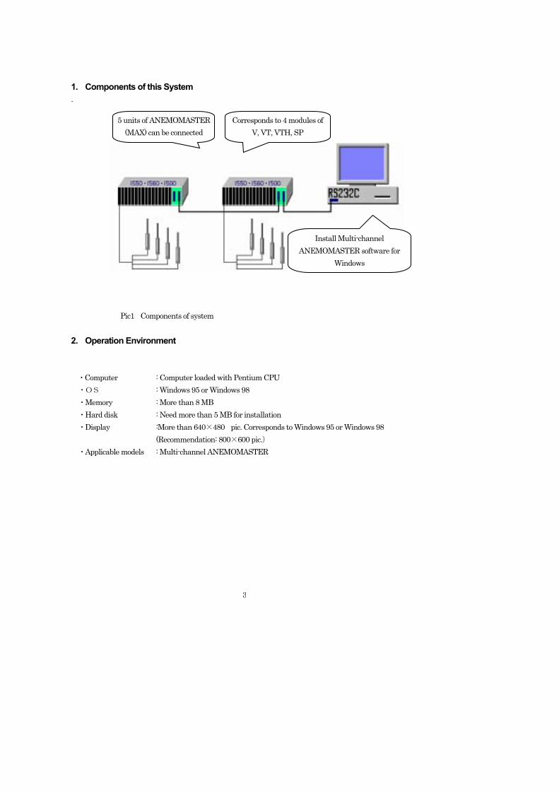
1. Components of this System .
Pic1 Components of system 2. Operation Environment ・Computer : Computer loaded with Pentium CPU
・OS : Windows 95 or Windows 98 ・Memory : More than 8 MB ・Hard disk : Need more than 5 MB for installation ・Display :More than 640×480 pic. Corresponds to Windows 95 or Windows 98 (Recommendation: 800×600 pic.) ・Applicable models : Multi-channel ANEMOMASTER
5 units of ANEMOMASTER (MAX) can be connected
Corresponds to 4 modules of V, VT, VTH, SP
Install Multi-channel ANEMOMASTER software for
Windows
4
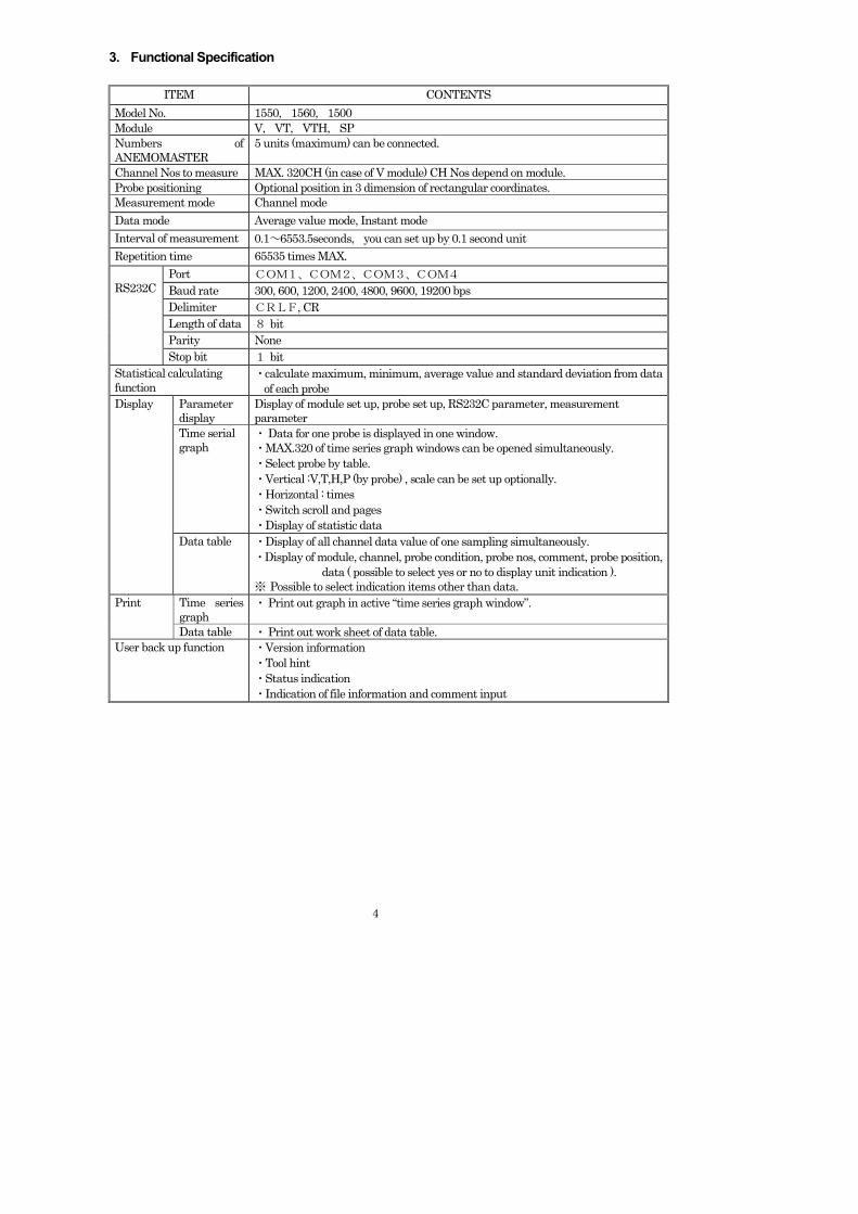
3. Functional Specification
ITEM CONTENTS Model No. 1550, 1560, 1500 Module V, VT, VTH, SP Numbers of ANEMOMASTER
5 units (maximum) can be connected.
Channel Nos to measure MAX. 320CH (in case of V module) CH Nos depend on module. Probe positioning Optional position in 3 dimension of rectangular coordinates. Measurement mode Channel mode Data mode Average value mode, Instant mode Interval of measurement 0.1~6553.5seconds, you can set up by 0.1 second unit Repetition time 65535 times MAX.
Port COM1、COM2、COM3、COM4 Baud rate 300, 600, 1200, 2400, 4800, 9600, 19200 bps Delimiter CRLF, CR Length of data 8 bit Parity None
RS232C
Stop bit 1 bit Statistical calculating function
・calculate maximum, minimum, average value and standard deviation from data of each probe
Parameter display
Display of module set up, probe set up, RS232C parameter, measurement parameter
Time serial graph
・ Data for one probe is displayed in one window. ・MAX.320 of time series graph windows can be opened simultaneously. ・Select probe by table. ・Vertical :V,T,H,P (by probe) , scale can be set up optionally. ・Horizontal : times ・Switch scroll and pages ・Display of statistic data
Display
Data table ・Display of all channel data value of one sampling simultaneously. ・Display of module, channel, probe condition, probe nos, comment, probe position, data ( possible to select yes or no to display unit indication ). ※ Possible to select indication items other than data.
Time series graph
・ Print out graph in active “time series graph window”. Print
Data table ・ Print out work sheet of data table. User back up function ・Version information
・Tool hint ・Status indication ・Indication of file information and comment input
5
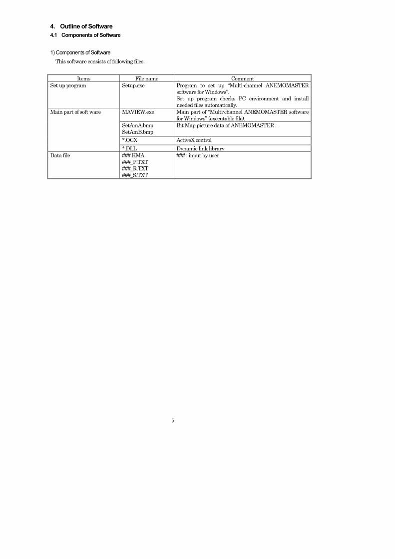
4. Outline of Software 4.1 Components of Software 1) Components of Software This software consists of following files.
Items File name Comment Set up program Setup.exe Program to set up “Multi-channel ANEMOMASTER
software for Windows”. Set up program checks PC environment and install needed files automatically.
MAVIEW.exe Main part of “Multi-channel ANEMOMASTER software for Windows” (executable file).
SetAmA.bmp SetAmB.bmp
Bit Map picture data of ANEMOMASTER .
*.OCX ActiveX control
Main part of soft ware
*.DLL Dynamic link library Data file ###.KMA
###_P.TXT ###_R.TXT ###_S.TXT
### : input by user
6
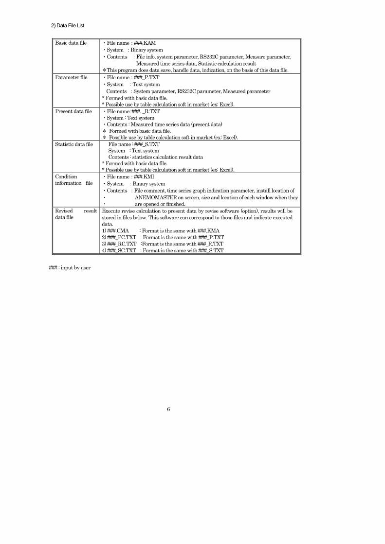
2) Data File List
Basic data file ・ File name:###.KAM ・ System :Binary system ・ Contents :File info, system parameter, RS232C parameter, Measure parameter, Measured time series data, Statistic calculation result *This program does data save, handle data, indication, on the basis of this data file.
Parameter file ・ File name:###_P.TXT ・ System :Text system Contents :System parameter, RS232C parameter, Measured parameter * Formed with basic data file. * Possible use by table calculation soft in market (ex: Excel).
Present data file ・ File name: ###. _R.TXT ・ System : Text system ・ Contents : Measured time series data (present data) * Formed with basic data file. * Possible use by table calculation soft in market (ex: Excel).
Statistic data file File name : ###_S.TXT System : Text system Contents : statistics calculation result data * Formed with basic data file. * Possible use by table calculation soft in market (ex: Excel).
Condition information file
・ File name:###.KMI ・ System :Binary system ・ Contents :File comment, time series graph indication parameter, install location of ・ ANEMOMASTER on screen, size and location of each window when they ・ are opened or finished.
Revised result data file
Execute revise calculation to present data by revise software (option), results will be stored in files below. This software can correspond to those files and indicate executed data. 1) ###.CMA : Format is the same with ###.KMA 2) ###_PC.TXT : Format is the same with ###_P.TXT 3) ###_RC.TXT :Format is the same with ###_R.TXT 4) ###_SC.TXT : Format is the same with ###_S.TXT
### : input by user
7
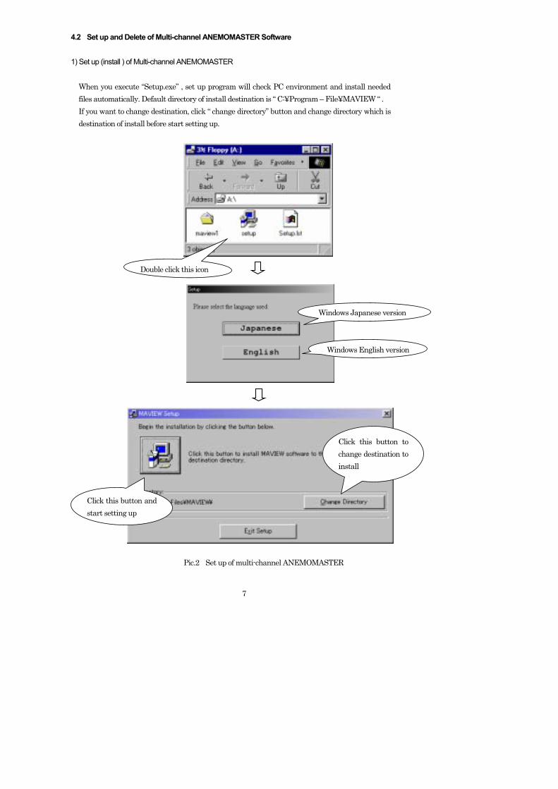
4.2 Set up and Delete of Multi-channel ANEMOMASTER Software 1) Set up (install ) of Multi-channel ANEMOMASTER
When you execute “Setup.exe” , set up program will check PC environment and install needed files automatically. Default directory of install destination is “ C:¥Program – File¥MAVIEW “ . If you want to change destination, click “ change directory” button and change directory which is destination of install before start setting up.
Pic.2 Set up of multi-channel ANEMOMASTER
Click this button and start setting up
Double click this icon
Windows Japanese version
Windows English version
Click this button to change destination to install
8
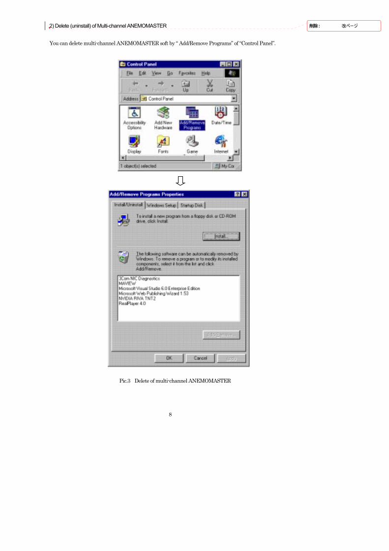
2) Delete (uninstall) of Multi-channel ANEMOMASTER You can delete multi-channel ANEMOMASTER soft by “ Add/Remove Programs” of “Control Panel”.
Pic.3 Delete of multi-channel ANEMOMASTER
削除 : 改ページ
9
4.3 Displays This program adopted Multi-document interface ( MDI ). This program opens basic data file ( *.KMA ) and indicate set up data and measurement data which are stored in files. More than two basic data files can not be opened simultaneously. Structure of display is as follows. (Figures in parentheses shows numbers of windows which can be indicated simultaneously.) Index screen [Pic. 4] Windows Module set up window (1) [Pic. 6, 17] Probe set up window (1) [Pic. 7, 18] Module set up indication window (1) Probe set up indication window (1) RS232C parameter indication window (1) Measurement parameter indication window (1) Time series graph indication window (1~320) [Pic. 23] Data table indication window (1) [Pic. 25] Dialogue box RS232C set up dialogue box [Pic. 9, 19] Measurement parameter set up dialogue box [Pic. 10, 20] Time series graph indication parameter set up dialogue box [Pic. 21] Time series graph : select probe to indicate dialogue box [ Pic. 22 ] Data table indication parameter set up dialogue box [Pic. 24] Version information dialogue box [Pic. 27] File information dialogue box [Pic. 29] Message dialogue box [Pic. 30, 31]
10
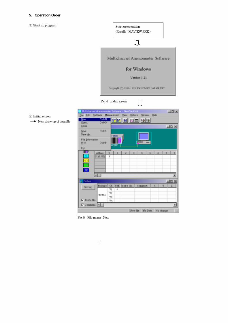
5. Operation Order ① Start up program Pic. 4 Index screen ② Initial screen New draw up of data file Pic. 5 File menu : New
Start up operation (Exe.file : MAVIEW.EXE )
11
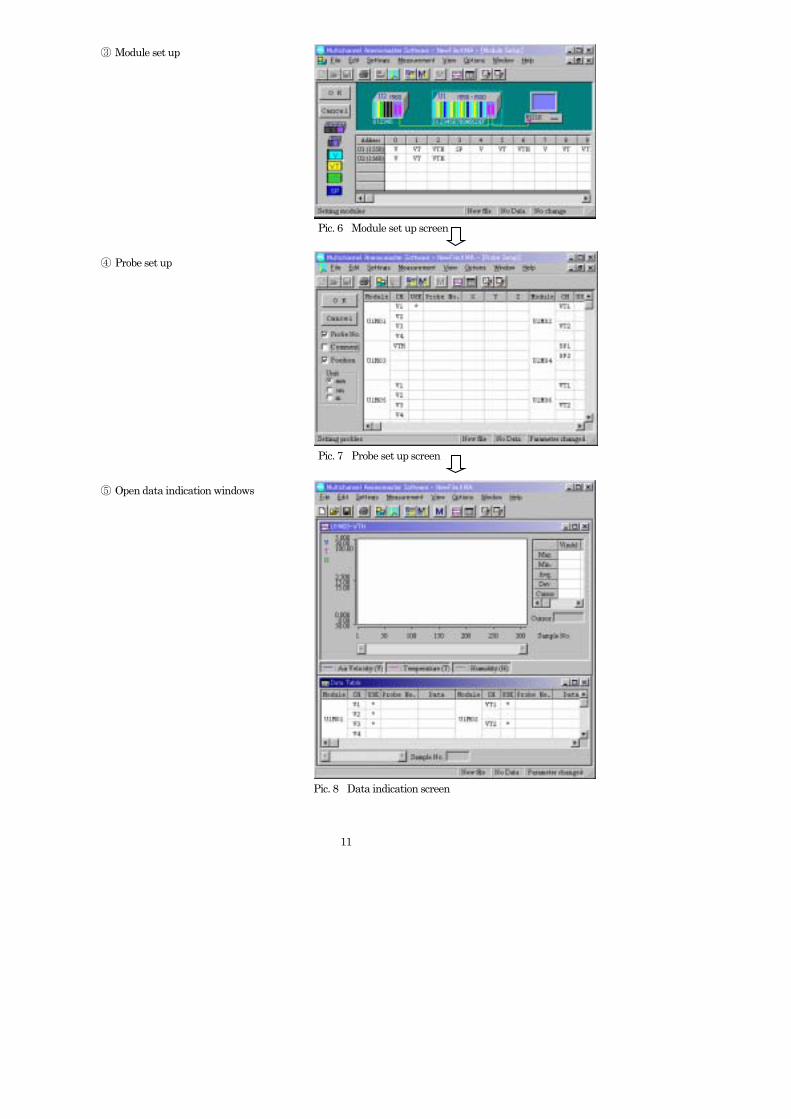
③ Module set up Pic. 6 Module set up screen ④ Probe set up Pic. 7 Probe set up screen ⑤ Open data indication windows Pic. 8 Data indication screen
12
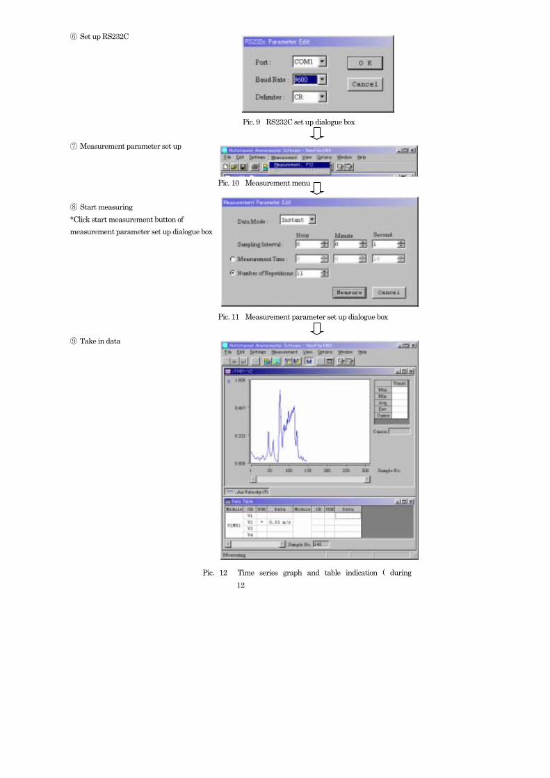
⑥ Set up RS232C Pic. 9 RS232C set up dialogue box ⑦ Measurement parameter set up Pic. 10 Measurement menu ⑧ Start measuring *Click start measurement button of measurement parameter set up dialogue box Pic. 11 Measurement parameter set up dialogue box ⑨ Take in data Pic. 12 Time series graph and table indication ( during
13
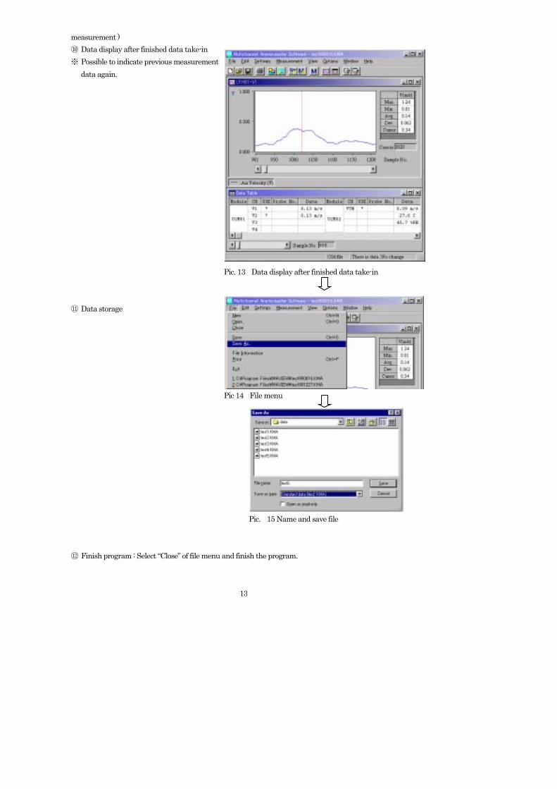
measurement ) ⑩ Data display after finished data take-in ※ Possible to indicate previous measurement data again. Pic. 13 Data display after finished data take-in ⑪ Data storage Pic 14 File menu Pic. 15 Name and save file ⑫ Finish program : Select “Close” of file menu and finish the program.
14
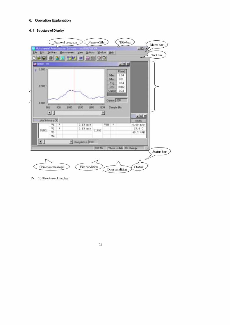
6. Operation Explanation 6. 1 Structure of Display Operation Area Pic. 16 Structure of display
Name of program Name of file Title bar Menu bar
Tool bar
Common message File condition Data condition
Status bar
Status
15
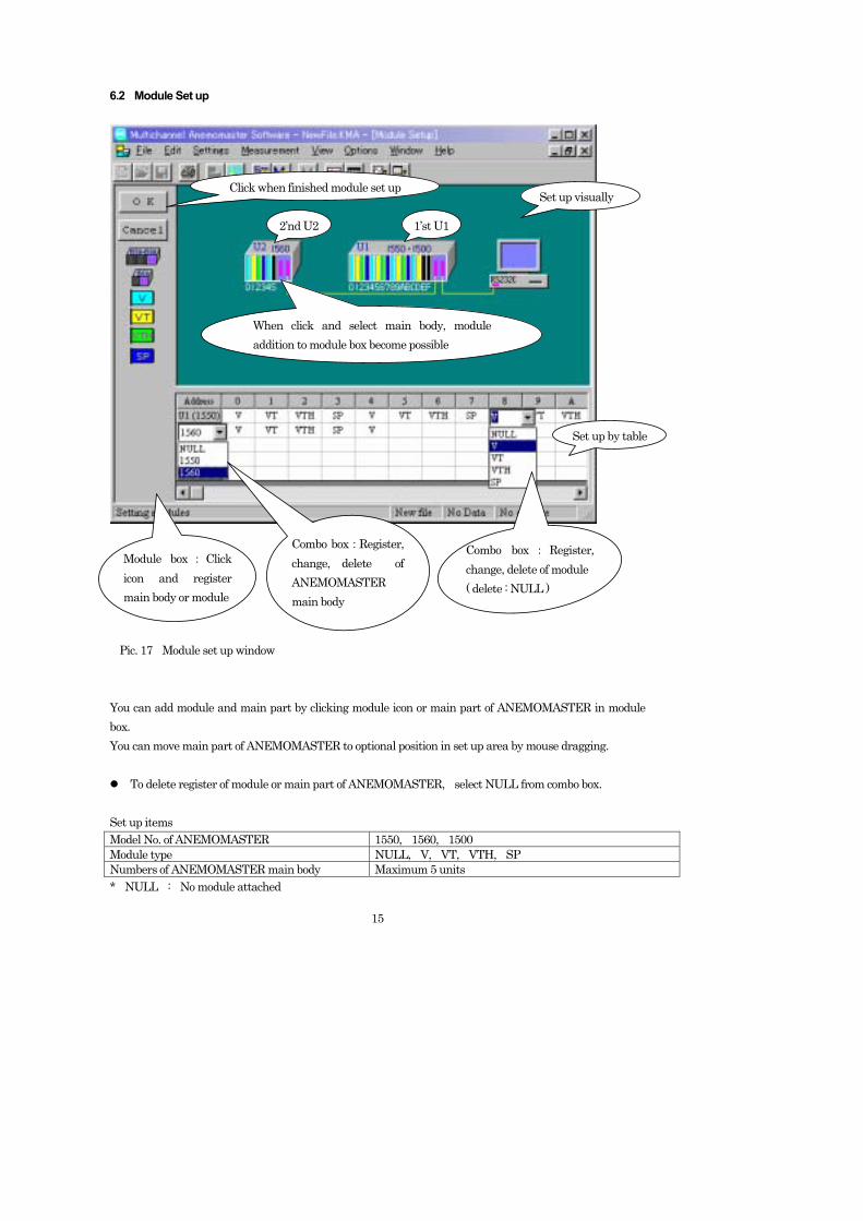
6.2 Module Set up Pic. 17 Module set up window You can add module and main part by clicking module icon or main part of ANEMOMASTER in module box. You can move main part of ANEMOMASTER to optional position in set up area by mouse dragging.
To delete register of module or main part of ANEMOMASTER, select NULL from combo box. Set up items Model No. of ANEMOMASTER 1550, 1560, 1500 Module type NULL, V, VT, VTH, SP Numbers of ANEMOMASTER main body Maximum 5 units * NULL : No module attached
Click when finished module set up
2’nd U2 1’st U1
Set up visually
When click and select main body, module addition to module box become possible
Module box : Click icon and register main body or module
Combo box:Register, change, delete of ANEMOMASTER main body
Set up by table
Combo box : Register, change, delete of module ( delete : NULL )
16
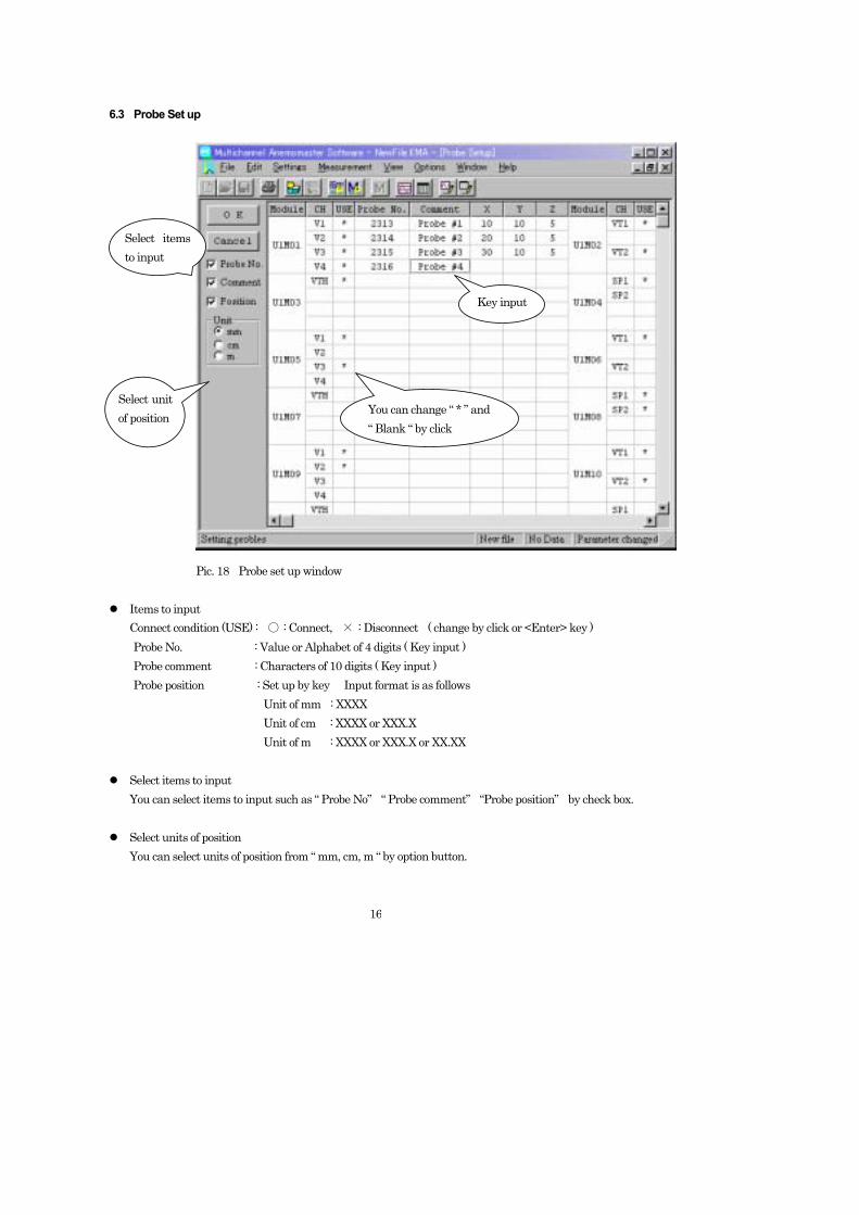
6.3 Probe Set up Pic. 18 Probe set up window
Items to input Connect condition (USE) : 〇 : Connect, × : Disconnect ( change by click or <Enter> key )
Probe No. : Value or Alphabet of 4 digits ( Key input ) Probe comment : Characters of 10 digits ( Key input ) Probe position : Set up by key Input format is as follows Unit of mm : XXXX Unit of cm : XXXX or XXX.X Unit of m : XXXX or XXX.X or XX.XX
Select items to input You can select items to input such as “ Probe No” “ Probe comment” “Probe position” by check box.
Select units of position
You can select units of position from “ mm, cm, m “ by option button.
Select items to input
Select unit of position
Key input
You can change “ * ” and “ Blank “ by click
17
6.4 RS232C Set up
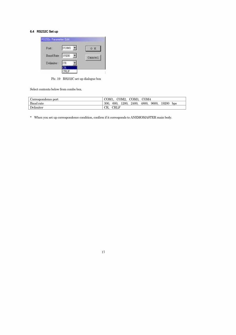
Pic. 19 RS232C set up dialogue box Select contents below from combo box. Correspondence port COM1, COM2, COM3, COM4 Baud rate 300, 600, 1200, 2400, 4800, 9600, 19200 bps Delimiter CR, CRLF * When you set up correspondence condition, confirm if it corresponds to ANEMOMASTER main body.
18
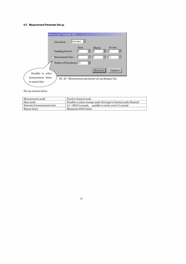
6.5 Measurement Parameter Set up Pic. 20 Measurement parameter set up dialogue box Set up contents below. Measurement mode Fixed to channel mode Data mode Possible to select average mode (Average) or Instant mode (Instant) Interval of measurement time 0.1~6553.5 seconds, possible to set by every 0.1 second Repeat times Maximum 65535 times
Possible to select measurement times or repeat time
19
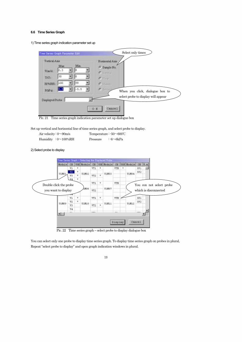
6.6 Time Series Graph 1) Time series graph indication parameter set up Pic. 21 Time series graph indication parameter set up dialogue box Set up vertical and horizontal line of time series graph, and select probe to display. Air velocity : 0~90m/s Temperature : -50~600℃ Humidity : 0~100%RH Pressure : -6~6kPa 2) Select probe to display Pic. 22 Time series graph – select probe to display dialogue box You can select only one probe to display time series graph. To display time series graph on probes in plural, Repeat “select probe to display” and open graph indication windows in plural.
Select only times
When you click, dialogue box to select probe to display will appear
Double click the probe you want to display
You con not select probe which is disconnected
20
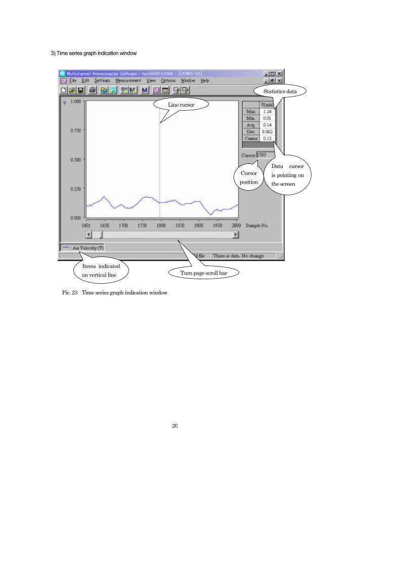
3) Time series graph indication window Pic. 23 Time series graph indication window Pic. 23 Time series graph indication window
Statistics data
Cursor position
Line cursor
Items indicated on vertical line Turn page scroll bar
Data cursor is pointing on the screen
21
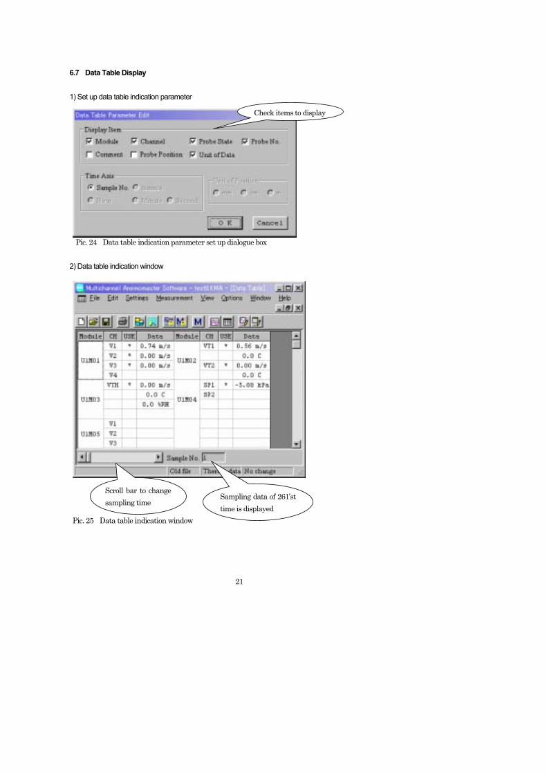
6.7 Data Table Display 1) Set up data table indication parameter Pic. 24 Data table indication parameter set up dialogue box 2) Data table indication window Pic. 25 Data table indication window
Check items to display
Scroll bar to change sampling time
Sampling data of 261’st time is displayed
22
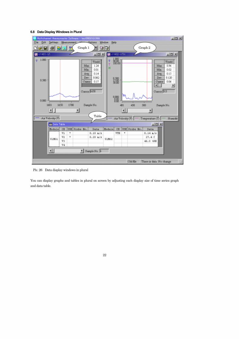
6.8 Data Display Windows in Plural Pic. 26 Data display windows in plural You can display graphs and tables in plural on screen by adjusting each display size of time series graph and data table.
Graph 1 Graph 2
Table

23
6.9 Print Out This program is possible to print out time series data graph and data table. Orders of print out: a. Click and active window of time series graph (or data table ) you want to print out. b. Select “Print out” item from “File” menu (or click print out icon of tool bar).
24
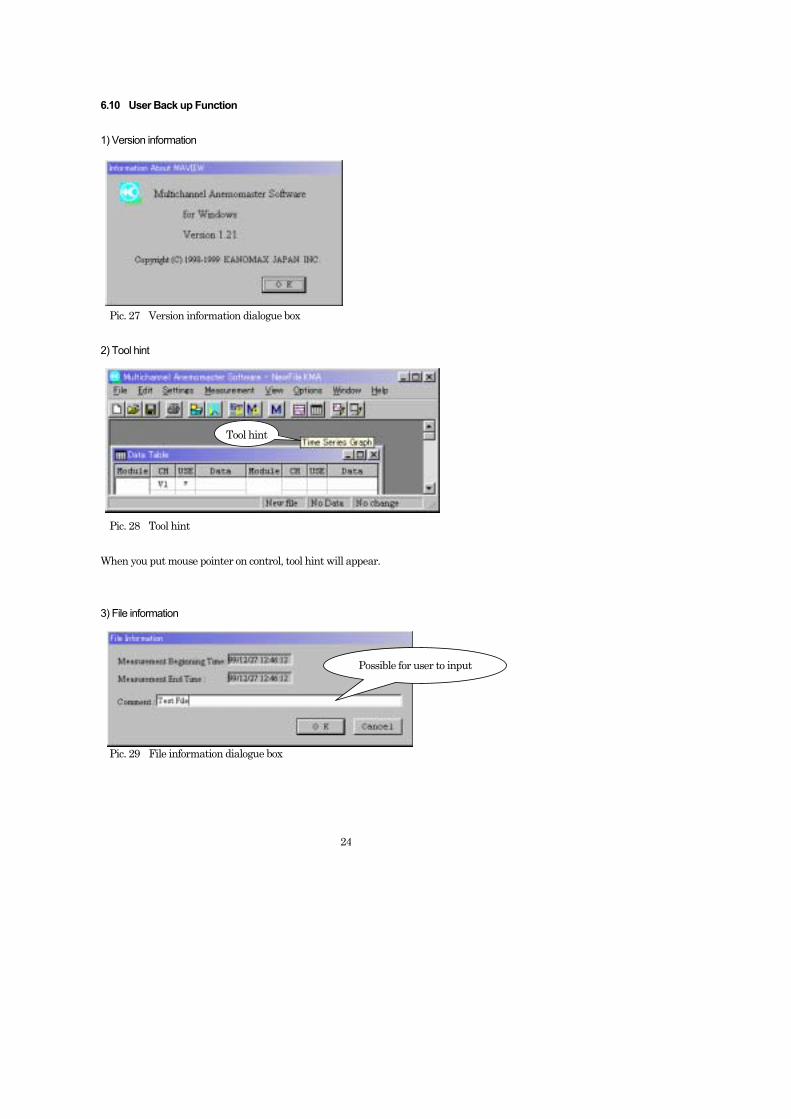
6.10 User Back up Function 1) Version information Pic. 27 Version information dialogue box 2) Tool hint Pic. 28 Tool hint When you put mouse pointer on control, tool hint will appear. 3) File information Pic. 29 File information dialogue box
Tool hint
Possible for user to input
25
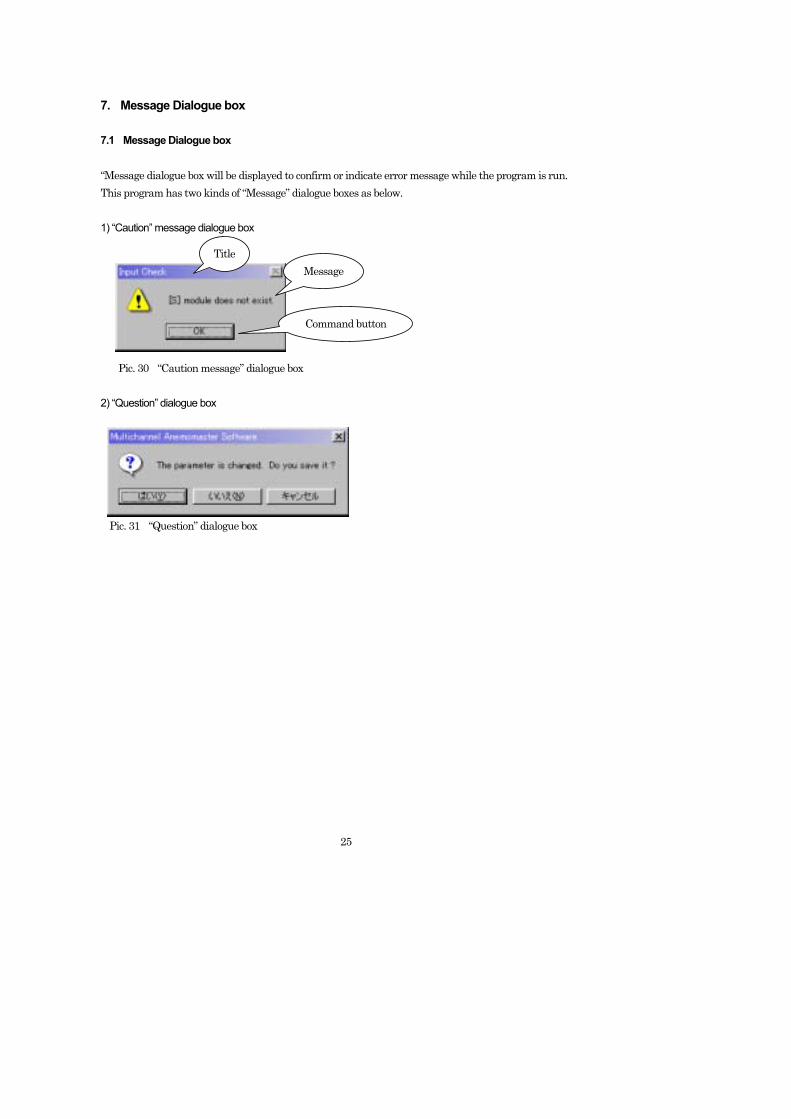
7. Message Dialogue box 7.1 Message Dialogue box “Message dialogue box will be displayed to confirm or indicate error message while the program is run. This program has two kinds of “Message” dialogue boxes as below. 1) “Caution” message dialogue box Pic. 30 “Caution message” dialogue box 2) “Question” dialogue box Pic. 31 “Question” dialogue box
Title Message
Command button
26
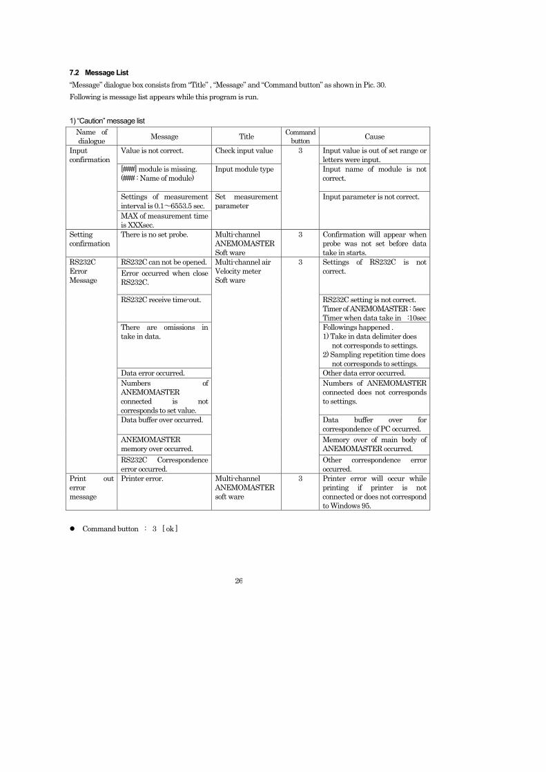
7.2 Message List “Message” dialogue box consists from “Title” , “Message” and “Command button” as shown in Pic. 30. Following is message list appears while this program is run. 1) “Caution” message list
Name of dialogue Message Title Command
button Cause
Value is not correct. Check input value Input value is out of set range or letters were input.
[###] module is missing. (### : Name of module)
Input module type Input name of module is not correct.
Settings of measurement interval is 0.1~6553.5 sec.
Input confirmation
MAX of measurement time is XXXsec.
Set measurement parameter
3
Input parameter is not correct.
Setting confirmation
There is no set probe. Multi-channel ANEMOMASTER Soft ware
3 Confirmation will appear when probe was not set before data take in starts.
RS232C can not be opened. Error occurred when close RS232C.
Settings of RS232C is not correct.
RS232C receive time-out. RS232C setting is not correct. Timer of ANEMOMASTER : 5sec Timer when data take in :10sec
There are omissions in take in data.
Followings happened . 1) Take in data delimiter does not corresponds to settings. 2) Sampling repetition time does not corresponds to settings.
Data error occurred. Other data error occurred. Numbers of ANEMOMASTER connected is not corresponds to set value.
Numbers of ANEMOMASTER connected does not corresponds to settings.
Data buffer over occurred.
Data buffer over for correspondence of PC occurred.
ANEMOMASTER memory over occurred.
Memory over of main body of ANEMOMASTER occurred.
RS232C Error Message
RS232C Correspondence error occurred.
Multi-channel air Velocity meter Soft ware
3
Other correspondence error occurred.
Print out error message
Printer error. Multi-channel ANEMOMASTER soft ware
3 Printer error will occur while printing if printer is not connected or does not correspond to Windows 95.
Command button : 3 [ ok ]
27
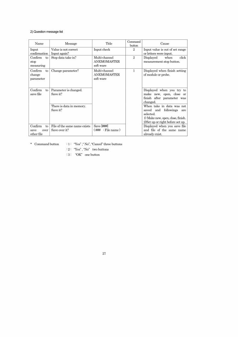
2) Question message list
Name Message Title Command button Cause
Input confirmation
Value is not correct Input again?
Input check 2 Input value is out of set range or letters were input.
Confirm to stop measuring
Stop data take in? Multi-channel ANEMOMASTER soft ware
2 Displayed when click measurement stop button.
Confirm to change parameter
Change parameter? Displayed when finish setting of module or probe.
Parameter is changed. Save it?
Displayed when you try to make new, open, close or finish after parameter was changed.
Confirm to save file
There is data in memory. Save it?
Multi-channel ANEMOMASTER soft ware
When take in data was not saved and followings are selected. 1) Make new, open, close, finish. 2)Set up or right before set up.
Confirm to save over other file
File of the same name exists Save over it?
Save [###] ( ### : File name )
1
Displayed when you save file and file of the same name already exist.
* Command button : 1 : “Yes” ,“ No”, “Cancel” three buttons : 2 : “Yes” , “No” two buttons : 3 : “OK” one button

28
8. Data Link to Calculation Table Soft This program create data file which can be taken in to calculation table soft at the same time with data saving of Measured data. Data file which can be taken in to calculation table soft File Parameter file *File name : ###_P.TXT
*System : Text system *Contents : System parameter, RS232C parameter, measurement parameter.
Present data file *File name : ###_R.TXT *System : Text system *Contents : Time series data of measured time .
Statistics data file *File name : ###_S.TXT *System : Text system Contents : Statistics calculation result data.
Revised result data file Do revise calculation to present data using revision soft ware, ( option ) and save that result to files below 1) ###_PC.TXT : Format is the same with ###_P.TXT 2) ###_RC.TXT : Format is the same with ###_R.TXT 3) ###_SC.TXT : Format is the same with ###_S.TXT
### : Input by user Caution : If you need to use calculation table soft ( ex. : Excel), you have to buy it as option. Operation order ( ex. : Excel) ① Start up Excel
Select [ File ] – [ Open ]
Open file
29
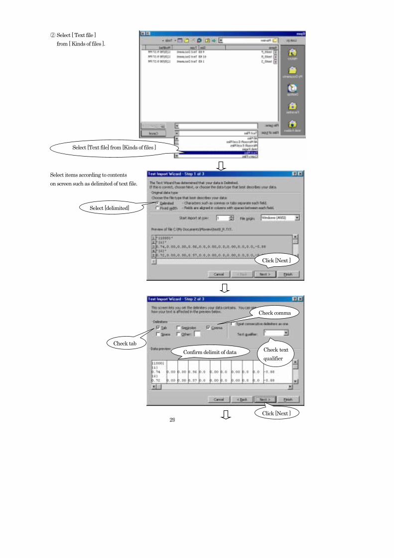
② Select [ Text file ]
from [ Kinds of files ]. Select items according to contents on screen such as delimited of text file.
Select [Text file] from [Kinds of files ]
Select [delimited]
Click [Next ]
Check tab
Check comma
Confirm delimit of data Check text qualifier
Click [Next ]
30
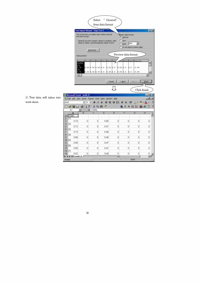
④ Text data will taken into work sheet.
Select “ General” from data format
Preview data format
Click finish