MSE Wall Design and Construction Policy Updates - … Road School MSE...MSE Wall Design and...
90
MSE Wall Design and Construction Policy Updates Anne Rearick Athar Khan Bridge Director, INDOT Manager, INDOT Office of Geotechnical Services March 7, 2017
Transcript of MSE Wall Design and Construction Policy Updates - … Road School MSE...MSE Wall Design and...

MSE Wall Design and Construction Policy Updates
Anne Rearick Athar KhanBridge Director, INDOT Manager, INDOT Office of
Geotechnical Services
March 7, 2017

Overview Background Design Memo 17-03 Preconstruction Review Shop Plan Review Construction Materials Inspection Field Inspection Checklist Questions

MSE Wall Problems
Backfill LeakageBulging Panels
Site Drainage

Modular block wall: Typical extensible reinforcement
Precast concrete panel type of wall: Uses both extensible or inextensible reinforcement
Note: Current Indiana specification only allows inextensible reinforcement with precast concrete panel type of MSE wall.
Slide 4
MSE Walls Term “MSE” : Mechanically Stabilized EarthTypes of MSE walls:

Typical Section Of MSE Wall

Roles and Responsibilities
Per INDOT Standard Specifications 731.03 The internal and external stability shall be the
responsibility of the contractor. The global stability will be the responsibility of the
engineer.

MSE Wall Design Memo 17-03
Issued March 1, 2017 Effective Immediately
Covers MSE Wall review process MSE Wall Suitability IDM Revisions Plan Requirements

MSE Wall Review Process
Stage of Plan Development (as of the date of the memo)
Review by Geotechnical
Services?
When to Submit
Information to Submit
Prior to Stage 1Yes
Concurrent with
Geotechnical Investigation
Request
Stage 1 plans, including
preliminary wall layout.
After Stage 1 and Before
Stage 3Yes
Immediately
Current plan set or Title Sheet, Plan
and Profile, Detail Sheets*
After Stage 3Yes, where
guidance below has not been
accounted for in the plans.
Coordinate with
Geotechnical Services
immediately
As determined during
coordination with Geotechnical
Services* Detail sheets include wall layout/geometry, wall section view, known obstructions, known foundation improvement requirements.

MSE Wall Review Process Office of Geotechnical Engineering concurrence is
required agreeing that the use of an MSE wall is suitable for projects that have not yet reached Stage 1.
A second submittal at Stage 3 may be necessary if additional detail is required. This will be noted when the first review is returned.
Revisions to plans based upon this memo will be expected for projects prior to Stage 3.
Revisions to plans for projects beyond Stage 3 will be determined on a project to project basis with full coordination.

MSE Wall SuitabilityLook for most economical solution
MSE is often not the best option in cut or limited right of way situations
Consider all possible alternatives Consider facing options Consider the effect of wall curvature
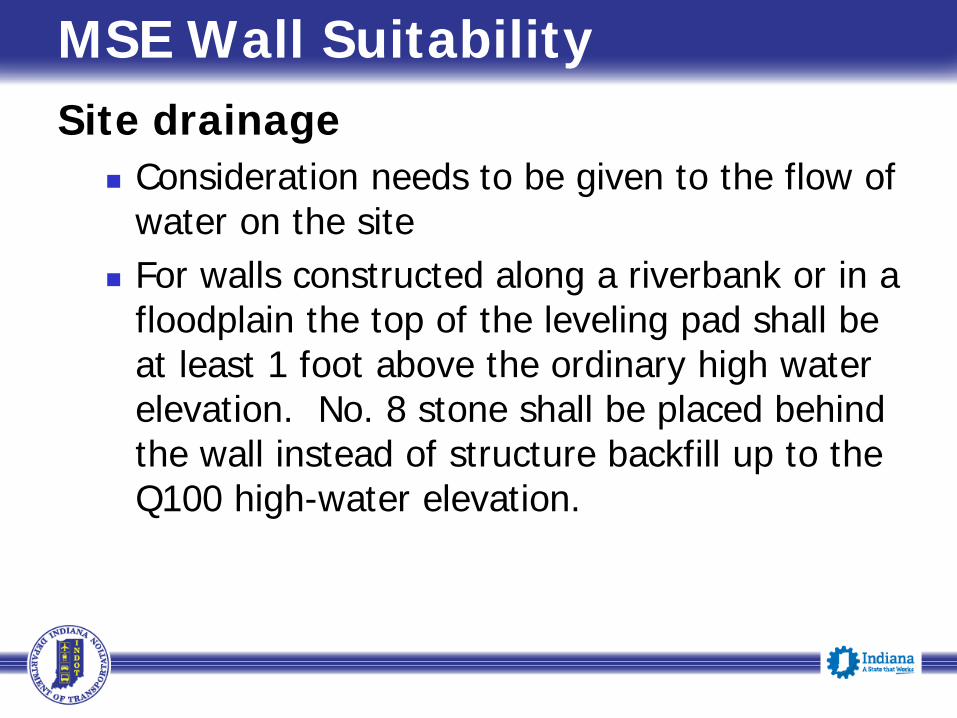
MSE Wall SuitabilitySite drainage
Consideration needs to be given to the flow of water on the site
For walls constructed along a riverbank or in a floodplain the top of the leveling pad shall be at least 1 foot above the ordinary high water elevation. No. 8 stone shall be placed behind the wall instead of structure backfill up to the Q100 high-water elevation.

MSE Wall SuitabilityPotential obstructions
Utilities other than wall drainage Floodplain erosion and scour potential Potential corrosion of reinforcement due to
contaminated ground water or other environmental considerations
MSE Wall IDM Revisions
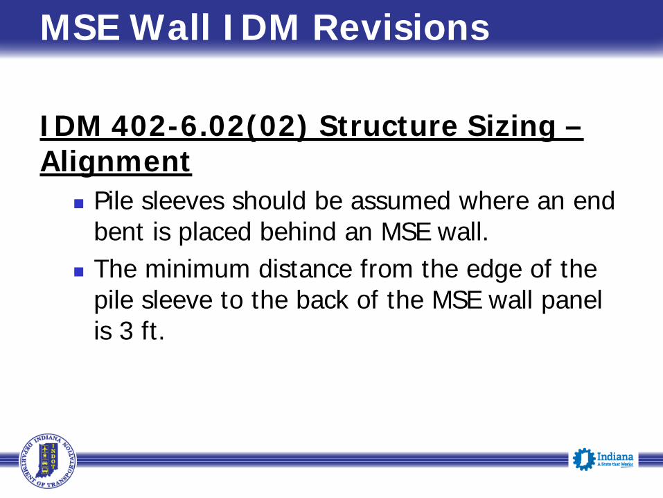
IDM 402-6.02(02) Structure Sizing –Alignment
Pile sleeves should be assumed where an end bent is placed behind an MSE wall.
The minimum distance from the edge of the pile sleeve to the back of the MSE wall panel is 3 ft.

MSE Wall IDM RevisionsIDM 409-2.04(02) Integral End Bent –Design Requirements, 409-3.03 Semi-Integral End Bent, and Figure 409-2G
Figure 409-2G illustrates the minimum distance from the edge of the pile sleeve to the back of the MSE wall panel and preferred MSE wall configurations at an end bent.

MSE Wall IDM Revisions

MSE Wall IDM Revisions
MSE Wall IDM RevisionsIDM 410-5.01(06), Design Criteria
Where two intersecting walls form an enclosed angle, the angle is to be greater than or equal to 70 degrees.
Sharp curves should be avoided in the wall layout.
Utilities should not be placed through the reinforced zone. Where utility placement in the reinforced zone is unavoidable, future access must be provided to the utility without disrupting the reinforcement.

MSE Wall IDM Revisions
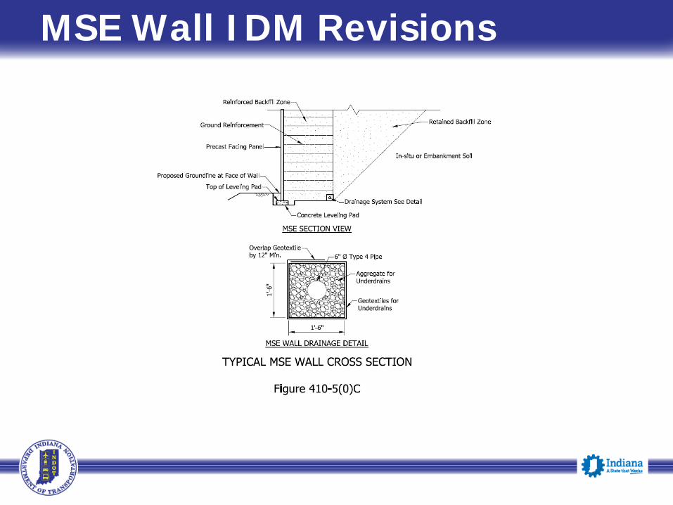
IDM 410-5.01(07), Figure 410-5(0)C (New), Information to be Shown on Plans
Drainage systems are required for all MSE walls. Figure 410-5(0)C illustrates a typical MSE wall cross sections and provides the drainage details to be included on plans.
MSE Wall IDM Revisions

MSE Wall IDM Revisions
IDM 410-5.01(07), Figure 410-5(0)C (New), Information to be Shown on Plans (Cont.)
A plan view showing all obstructions and their offset from the back of the MSE wall is required on the MSE Wall Details sheet. Obstructions include but are not limited to, piles, pile sleeves, catch basins, signal or sign foundation, guardrail posts, and culverts.
Where an obstruction projects through the MSE wall panel, the obstruction should also be shown in an isolated section and elevation view.
MSE Wall IDM Revisions
IDM 410-5.01(07), Figure 410-5(0)C (New), Information to be Shown on Plans (Cont.)
Modifications to the wall design to avoid obstructions must be shown in the MSE Wall working drawings. Design options for obstructions within the reinforced zone are described in the AASHTO LRFD Bridge Design Specifications, section 11.10.10.4.

MSE Wall IDM Revisions
IDM 410-5.01(07), Figure 410-5(0)C (New), Information to be Shown on Plans (Cont.)
When an end bent is placed behind an MSE wall, expanded polystyrene should be shown for gap between the front face of the end bent and the back of the MSE wall. Do not show Styrofoam or extruded polystyrene.

Plan Requirements Show and label all obstructions
Plan view shall show the distance from the back of the panel.
Elevation view shall show all obstructions that project through a panel.
Show all the details of ground improvement if specified in the Geotechnical Report
Consider adding a section view Show site drainage

3/15/2017
Example Drainage Problems

Preconstruction Review
The plans and specifications The site conditions relevant to
construction requirements Review of Geotechnical Report Material requirements Construction Sequences for the specific
reinforcement system Shop Drawing Submittal & Approval

MSE Wall Shop Plan Review Construction Memo 13-13 Revised (9/15/15)

MSE Wall Shop Plan ReviewConstruction Memo 13-13 Revised (9/15/15)
Shop plans and design calculations are to be stamped by a PE and are to be submitted to the designer of record
The designer of record will forward a copy to the INDOT Office of Geotechnical Engineering
The Office of Geotechnical Engineering will review and provide comments back to the designer of record
The designer of record will provide the final approval

MSE Wall Shop Plan ReviewItems to be considered
Adherence to the AASHTO LRFD Design Specifications
11.10.1…. When two intersecting walls form an enclosed angle of 70 degrees or less, the affected portion of the wall shall be designed as an internally tied bin structure with at-rest earth pressure coefficients. C11.10.10.4The max splay of reinforcements is limited to a maximum of 15 degrees

MSE Wall Shop Plan ReviewItems to be considered
Treatment of obstructions 11.10.10.4 addresses obstructions in the
reinforced soil zone1. If reinforcement is to be partially or fully severed in the
location of the obstruction, design the surrounding reinforcement layers to carry the additional load…
2. Place a structural frame around the obstruction capable of carrying the load from the reinforcements…
3. If the soil reinforcements consist of discrete strips and depending on the size and location of the obstruction, it may be possible to splay the reinforcements around the obstruction
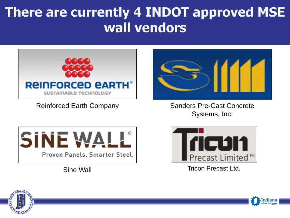
Reinforced Earth Company Sanders Pre-Cast Concrete Systems, Inc.
Sine Wall Tricon Precast Ltd.

Sine Wall Syst em to use r ippled Str ip

Sanders Tricon
≠
≠Reinforcement tensile strength
Reinforcement-soil frictional capacity

MSE Wall

MSE Wall
Indiana Toll Road Improvement in Gary

MSE Wall
Materials Inspection
Prefabricated Precast Concrete Elements Reinforcing ElementsOther Materials Facing Joint Materials Reinforced backfill Retained backfill
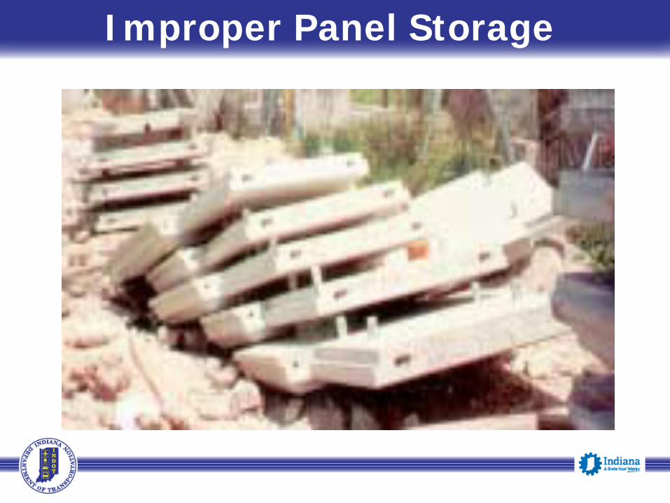
Improper Panel Storage

Proper Panel Storage

Improper Storage of Reinforcement

Proper Storage of Reinforcement

Joint Material

Joint Material

Backfill Material Type 3 structure backfill within reinforced backfill
zone excluding # 30 sand meeting INDOT Specs Unit weight shall not be less than 120 pcf unless
light weight is specified Internal friction angle (ᵩ) of 34 degree for structure
backfill within reinforced backfill zone “B” Borrow or structure backfill within retained
backfill zone with Internal friction angle (ᵩ) of 30 degree

Construction Control
Site Preparation Leveling Pad Erection of Facing Elements Reinforced Fill Placement and
Compaction Placement of Reinforcing Elements

Site Preparation Cut to grade Remove unsuitable material as specified Proof roll the entire footprint area of MSE
wall to delineate any loose and/or unsuitable materials
Compact any loose material and remove and replace any unsuitable material
Perform DCP tests for verification

Excavation to Grade

Excavation to Grade
Leveling Pad
Excavate: for leveling pad Pour: unreinforced concrete leveling pad as
specified Curing time: at least 12 hrs before placing Panels Vertical tolerance: 3mm to design elevation Improperly Placed Leveling Pad: may result in
panel misalignment, cracking, and spalling

Leveling Pad

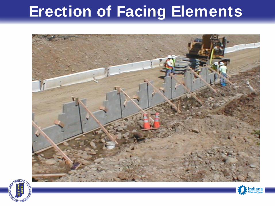
Erection of Facing Elements Always begin adjacent to any existing
structure and proceed toward the open end of the wall
Horizontal joint material or wooden shims should not be permitted between the first course of panels and the leveling pad except for panel battering
Vertical Backward Batter should not be more than 0.05 inch/foot of wall height

Erection of Facing Elements Use panel spacing bars for horizontal spacing
between panels First row of panels must be continuously braced
until several layers of reinforcements and backfill have been placed
Adjacent panels should be clamped together to prevent individual panel displacement
Since variety of panel types used on a project, facing element types must be checked to verify the installation exactly as shown on the plans

Erection of Facing Elements

Leveling Pads at Panel Step-up
000(6”-12”)

Erection of Facing Elements

Erection of Facing Elements
Erection of Facing Elements

Reinforced Fill Placement/Compaction
Mark your 6” compacted lift on the back side of the wall panels
Place backfill parallel to the wall and starting approximately 3 feet from the back of wall panel
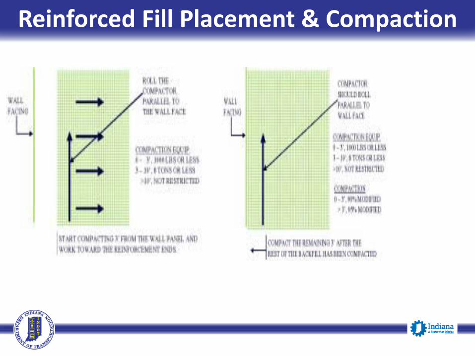
Level the fill by machinery moving parallel to the wall, windrowing toward the reinforcement ends
Lock the reinforcement and the panels in position Place the backfill not exceeding 5 “ in loose
thickness within 3 feet behind the wall by windrowing after locking the reinforcement

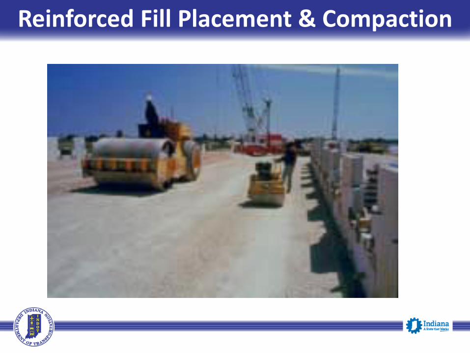
Compacting lift not exceeding 5 “ in loose thickness with a minimum of 5 passes using vibratory roller or plate weighing less than 1000 pounds
Except for the initial layer the fill must be brought up uniformly for the whole layer
Soil layers should be compacted up to or even slightly above the elevation of each level of reinforcement connections prior to placing that layer of reinforcement elements
Reinforced Fill Placement Compaction

Lift Thickness Marking on Facing Panel

Backfill Measurement Solution Template
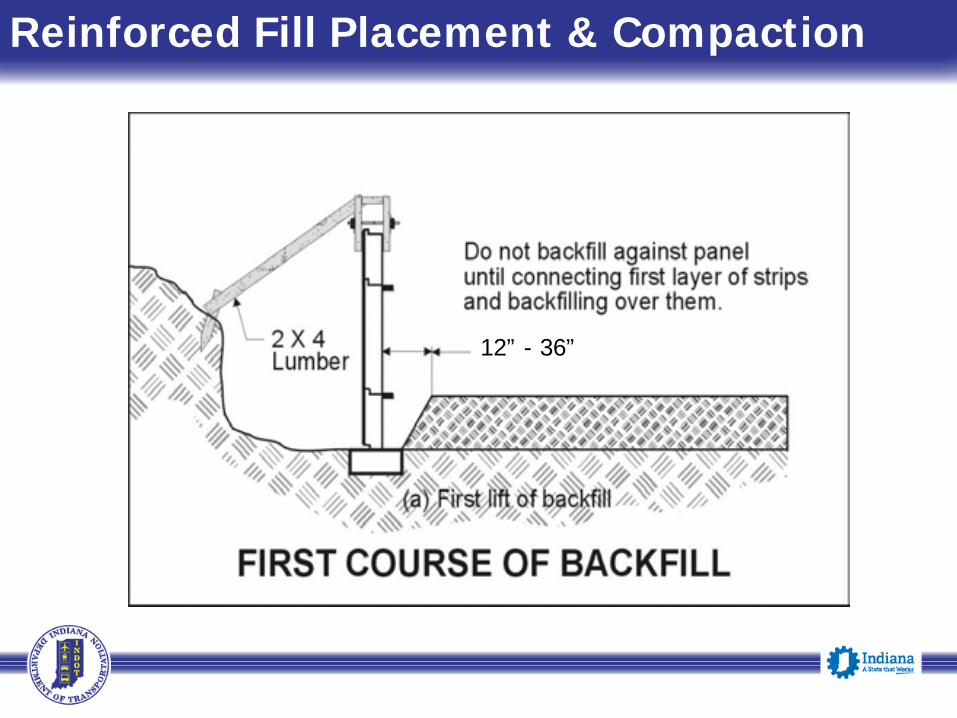
Reinforced Fill Placement & Compaction
12” - 36”
Reinforced Fill Placement & Compaction

Sheepfoot Rollers Not Allowed
Reinforced Fill Placement & Compaction

Reinforced Fill Placement & Compaction

Reinforced Fill Placement & Compaction
Reinforced Fill Placement & Compaction

Placement of Reinforcing Elements

Placement of Reinforcing Elements

Placement of Reinforcing Elements
Improper bolting at connections

Reinforcing Strip Connection to Facing
Placement of Reinforcing Elements

Placement of Reinforcing Elements
Straps not installed perpendicular to wall
Bent straps
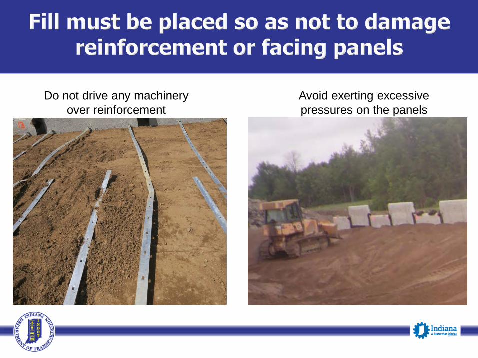
Do not drive any machinery over reinforcement
Avoid exerting excessive pressures on the panels

Broken connections with new brackets
Placement of Reinforcing Elements

Location of reinforcement connection
15° max

Geotechnical Initiatives Current:
Recent Specification Changes Standardized MSE Wall Recommendations Developed a Checklist for Construction Personnel Developed a Bearing Capacity Verification Table Developed a Training Course for construction Inspection
with the Assistance of the Research Division
Future: Modification to INDOT specs to address some design and
construction issues such as splay angle of 15 degrees Use of Type IC subgrade treatment on MSE walls Use of impervious Geomembrane over MSE walls Development of MSE Wall Inventory

Recent Specification Changes
Design:
Contractor: Responsible for Internal & External stability of the wall
Engineer: Responsible for Global stability Design Method: AASHTO LRFD Bridge Design Specification F* Value: Standardized use of AASHTO default values Tributary Area: Use as per FHWA-NHI-10-025

Recent Specification Changes
Material:
Unit weight: Structure backfill should be at least 120pcf, design values for foundation soil should be as per the Geotechnical report
Geotextile: Use at the interface between the reinforcedand retained backfill zones or adjacent soil

Recent Specification Changes
Construction: Foundation Preparation:
Proofrolling of the entire footprint of Reinforced backfill zone
Verification of foundation by DCP Testing Geotextile in conjunction with MSE wall construction
will not be measured or paid separately

MSE Wall- 731.07 Rev.
6 inches
6 inches
6 inches
6 inches
6 inches 2.5 ft. deep
N=5
N=5
N=5
N=5
N=5
DCP Tests for Foundation Requirement

The frequency of DCP measurements is: 1 DCP test for every 500 sq ft
Or5 DCP tests per end bent
Unsuitable areas shall be removed, replaced, and compacted in accordance with 203 and 211.
50 ft.
DCP
DCP Test Frequency
MSE Wall- 731.07 Rev.
( 500 sq ft area10 ft

Design Parameter Value (area 1)*Maximum Calculated Settlement "x" inchesMaximum Differentail Settlement "y" inchesTime for settlement completion "z" daysMaximum wall height XX ft
Design RecommendationsMinimum Reinformcement Length/Height Ratio 0.75H?? (example)Undercut required yes/noUndercut depth X feet??Undercut area from Sta. XX to XX line "XX"Undercut Backfill Material XXXXXXX
Seismic recommendationSite ClassSeismic ZonePeak Ground Accelaration As
Geotechnical Analysis Checks CDRSliding >=1.0Eccentricity >=1.0Global Stability Factor of safety/resistance factorFactored Bearing Resistance 5400 psf (example value)
Foundation Soils Strength Parameters**Cohesion internal friction angle Notes:*more sheets can be added to include recommendations for each area of concern.**if varying soil conditions encountered underneath the MSE wall, the table can be expanded to include all soil profile information
MSE Wall Geotechnical Design Parameter Table

The following is a general checklist to follow when constructing a Mechanically
Stabilized Earth wall (MSE wall). The answer to each of these should be yes unless
plans, specifications or specific approval has been given otherwise.
YES NO1. □ □ Has the contractor submitted wall shop drawings?2. □ □ Has the contractor submitted select backfill certification?3. □ □ Has the contractor furnished a copy of any instructions the
wall supplier may have furnished?4. □ □ Has the contractor supplied a Certificate of Compliance
that the wall materials comply with the applicable sectionsof the specifications? Has the contractor supplied a copy ofall test results performed by the Contractor supplier toassure compliance with specifications?
Check List

Check List YES NO
5. □ □ Have the shop drawings been approved?6. □ □ Has the geotechnical report been checked for undercutting?7. □ □ Did the contractor receive the correct panels (shape, size
and soil reinforcement connection layout) per theapproved shop drawings?
8. □ □ Did the contractor receive the correct reinforcement(proper length and size)?
9. □ □ Have the panels and the reinforcement been Inspected fordamage as outlined in the Specs?.

Check List YES NO
10. □ □ If any panels or soil reinforcement were found damagedhave they been rejected or repaired in accordance with
the specifications? 11. □ □ Are the panels and the soil reinforcement properly stored
to prevent damage?12. □ □ Has the MSE wall area been excavated to the proper
elevation?13. □ □ Has the area been proof rolled(a minimum of five passes
bya roller weighing a minimum of 8 tons)?
14. □ □ Has all soft or unsuitable materials been compacted orremoved and replaced?

Check List YES NO
15. □ □ Has the leveling pad area been properly excavated? 16. □ □ Has the leveling pad been set to the proper alignment?17. □ □ Has the leveling pad cured for a minimum of 12 hours?18. □ □ Is the first row of panels properly placed? Do they
have proper spacing, bracing, tilt and where required,do they the spacers installed?
19. □ □ Has the proper filter fabric and adhesive been supplied?20. □ □ Is the filter fabric being properly placed over the joints?21. □ □ Is the adhesive being applied to the panel, than the filter
fabric being placed?

Check List YES NO
22. □ □ Is the filter fabric stored properly away from sunlight andprotected from UV radiation?
23. □ □ Is the contractor using correct panels (size, shape &# of connections) for that panel’s wall location &
elevation? 24. □ □ Is fill being placed and compacted in 6 inch lifts?25. □ □ Is the equipments are kept off the reinforcement until a
minimum of 6 inches of fill is placed?26. □ □ Are the lifts being placed by the proper method and
sequence?27. □ □ Is the fill being compacted by the correct equipment and in
the correct pattern?28. □ □

Check List YES NO
28. □ □ Is the proper compaction being met within 3 feet of wall and greater than 3 feet from the wall based on DCP
criteria?29. □ □ Is the fill being brought up to or slightly above the soil
reinforcement elevation before the reinforcement are connected?
30. □ □ Is the reinforcement being properly connected?31. □ □ Is the soil reinforcement in the proper alignment?32. □ □ Is the vertical and horizontal alignments are checked
periodically and adjusted as needed?33. □ □ Is the contractor removing the wooden wedges as per
specification?

Check List YES NO
34. □ □ At the end of each day’s operation is the contractor shapingthe last level of backfill to permit a positive drainage awayfrom the wall such as temporary pipe etc.?
35. □ □ Has the contractor backfilled the front of the wall?
36. □ □ Is the correct coping being installed?
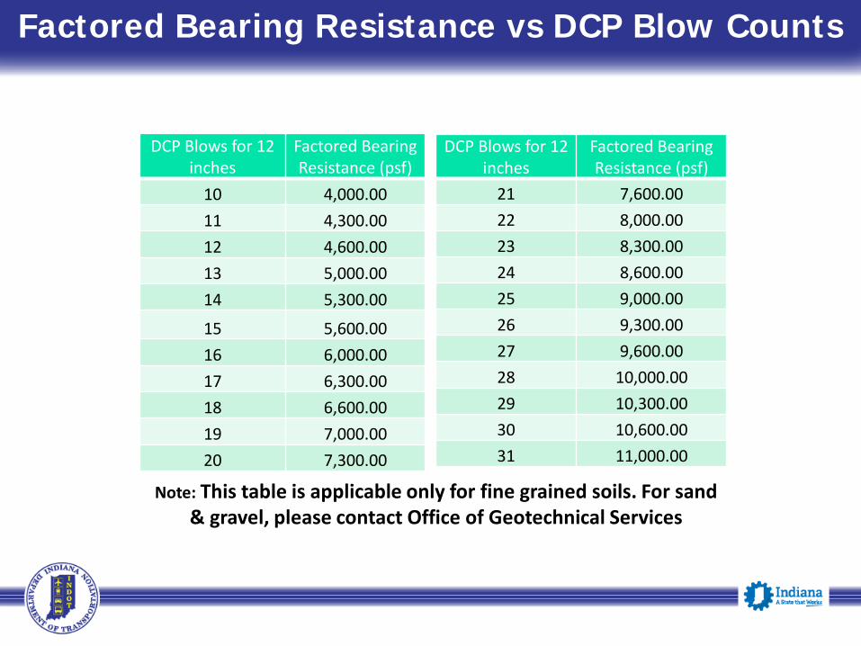
Factored Bearing Resistance Based on DCP Blow CountsDCP Blows for 12
inchesFactored Bearing Resistance (psf)
10 4,000.0011 4,300.0012 4,600.0013 5,000.0014 5,300.00
15 5,600.0016 6,000.0017 6,300.0018 6,600.0019 7,000.0020 7,300.00
DCP Blows for 12 inches
Factored Bearing Resistance (psf)
21 7,600.0022 8,000.0023 8,300.0024 8,600.0025 9,000.0026 9,300.0027 9,600.0028 10,000.0029 10,300.0030 10,600.0031 11,000.00
Note: This table is applicable only for fine grained soils. For sand & gravel, please contact Office of Geotechnical Services
Factored Bearing Resistance vs DCP Blow Counts

Questions
Anne RearickDirector of Bridges
Office: (317) 232-5152Email: [email protected]
Athar A. KhanManager, Office of Geotechnical Engineering
Office: (317) 610-7251 ext 219Email: [email protected]