
MP1764D Error Detector Operation Manual - dl.cdn · PDF fileError Detector Operation Manual...
154
Document No.: M-W2341AE-3.0 ANRITSU CORPORATION MP1764D Error Detector Operation Manual Read this manual before using the equipment. Keep this manual with the equipment. Third Edition
Transcript of MP1764D Error Detector Operation Manual - dl.cdn · PDF fileError Detector Operation Manual...

Document No.: M-W2341AE-3.0
ANRITSU CORPORATION
MP1764DError Detector
Operation Manual
Read this manual before using the equipment.Keep this manual with the equipment.
Third Edition

ii
Safety SymbolsTo prevent the risk of personal injury or loss related to equipment malfunction, Anritsu Corporation uses the followingsafety symbols to indicate safety-related information. Insure that you clearly understand the meanings of the sym-bols BEFORE using the equipment. Some or all of the following five symbols may not be used on all Anritsuequipment. In addition, there may be other labels attached to products which are not shown in the diagrams in thismanual.
Symbols used in manualThis indicates a very dangerous procedure that could result in serious injury ordeath if not performed properly.
This indicates a hazardous procedure that could result in serious injury or death ifnot performed properly.
This indicates a hazardous procedure or danger that could result in light-to-severeinjury, or loss related to equipment malfunction, if proper precautions are not taken.
Safety Symbols Used on Equipment and in ManualThe following safety symbols are used inside or on the equipment near operation locations to provide informationabout safety items and operation precautions. Insure that you clearly understand the meanings of the symbolsand take the necessary precautions BEFORE using the equipment.
This indicates a prohibited operation. The prohibited operation is indicated sym-bolically in or near the barred circle.
This indicates an obligatory safety precaution. The obligatory operation is indicat-ed symbolically in or near the circle.
This indicates warning or caution. The contents are indicated symbolically in ornear the triangle.
This indicates a note. The contents are described in the box.
These indicate that the marked part should be recycled.
MP1764DError DetectorOperation Manual
1 March 2004 (First Edition)13 July 2005 (Third Edition)
Copyright © 2004-2005, ANRITSU CORPORATION.All rights reserved. No part of this manual may be reproduced without the prior written permission of thepublisher.The contents of this manual may be changed without prior notice.Printed in Japan
DANGER
WARNING
CAUTION

For Safety
iii
WARNING 1. ALWAYS refer to the operation manual when working near locations
at which the alert mark shown on the left is attached. If the opera-tion, etc., is performed without heeding the advice in the operationmanual, there is a risk of personal injury. In addition, the equipmentperformance may be reduced.Moreover, this alert mark is sometimes used with other marks anddescriptions indicating other dangers.
2. Measurement CategoriesThis instrument is designed for Measurement category I (CAT I).Don’t use this instrument at the locations of measurement categoriesfrom CAT II to CAT IV.In order to secure the safety of the user making measurements, IEC61010 clarifies the range of use of instruments by classifying the lo-cation of measurement into measurement categories from I to IV.The category outline is as follows:Measurement category I (CAT I):Secondary circuits of a device connected to an outlet via a powertransformer etc.Measurement category II (CAT II):Primary circuits of a device with a power cord (portable tools, homeappliance etc.) connected to an outlet.Measurement category III (CAT III):Primary circuits of a device (fixed equipment) to which power is di-rectly supplied from the power distribution panel, and circuits from thedistribution panel to outlets.Measurement category IV (CAT IV):All building service-line entrance circuits through the integratingwattmeter and primary circuit breaker (power distribution panel).
3. When supplying power to this equipment, connect the accessory 3-pin power cord to a grounded outlet. If a grounded outlet is notavailable, before supplying power to the equipment, use a conversionadapter and ground the green wire, or connect the frame ground onthe rear panel of the equipment to ground. If power is suppliedwithout grounding the equipment, there is a risk of receiving a severeor fatal electric shock.
or

For Safety
iv
WARNING 4. This equipment cannot be repaired by the operator. DO NOT attempt
to remove the equipment covers or unit covers or to disassemble inter-nal components. Only qualified service technicians with a knowledgeof electrical fire and shock hazards should service this equipment.There are high-voltage parts in this equipment presenting a risk ofsevere injury or fatal electric shock to untrained personnel. In addition,there is a risk of damage to precision components.
5. The performance-guarantee seal verifies the integrity of the equipment.To ensure the continued integrity of the equipment, only Anritsu servicepersonnel, or service personnel of an Anritsu sales representative,should break this seal to repair or calibrate the equipment. If theperformance-guarantee seal is broken by you or a third party, theperformance of the equipment cannot be guaranteed.
6. This equipment should be used in the correct position. If the cabinetis turned on its side, etc., it will be unstable and may be damaged if itfalls over as a result of receiving a slight mechanical shock.And also DO NOT use this equipment in the position where the powerswitch operation is difficult.
7. DO NOT short the battery terminals and never attempt to disassem-ble it or dispose of it in a fire. If the battery is damaged by any ofthese actions, the battery fluid may leak.This fluid is poisonous.DO NOT touch it, ingest it, or get in your eyes. If it is accidentally in-gested, spit it out immediately, rinse your mouth with water and seekmedical help. If it enters your eyes accidentally, do not rub youreyes, irrigate them with clean running water and seek medical help.If the liquid gets on your skin or clothes, wash it off carefully and thor-oughly.
Repair
Falling Over
Battery Fluid
Calibration
For Safety
v
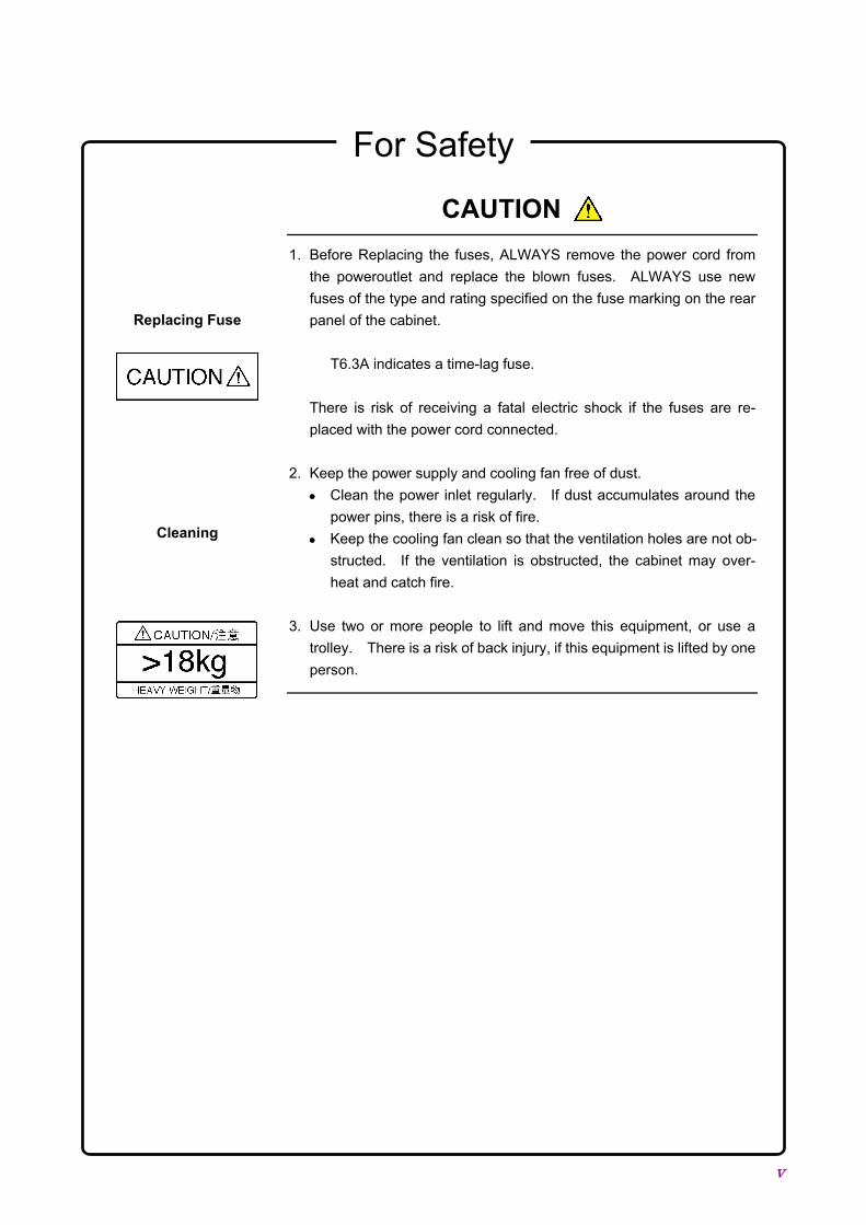
CAUTION 1. Before Replacing the fuses, ALWAYS remove the power cord from
the poweroutlet and replace the blown fuses. ALWAYS use newfuses of the type and rating specified on the fuse marking on the rearpanel of the cabinet.
T6.3A indicates a time-lag fuse.
There is risk of receiving a fatal electric shock if the fuses are re-placed with the power cord connected.
2. Keep the power supply and cooling fan free of dust.• Clean the power inlet regularly. If dust accumulates around the
power pins, there is a risk of fire.• Keep the cooling fan clean so that the ventilation holes are not ob-
structed. If the ventilation is obstructed, the cabinet may over-heat and catch fire.
3. Use two or more people to lift and move this equipment, or use atrolley. There is a risk of back injury, if this equipment is lifted by oneperson.
Replacing Fuse
Cleaning

For Safety
vi
CAUTION This equipment uses a Poly-carbomonofluoride lithium battery to back-up the memory. This battery must be replaced by a service engineerwhen it has reached the end of its useful life; contact the Anritsu salessection or your nearest representative.
Note: The battery used in this equipment has a maximum useful life of7 years. It should be replaced before this period has elapsed.
This equipment uses floppy disks for storing data and programs.
If this media is mishandled or becomes faulty, important data may be lost.To prevent this chance occurrence, all important data and programsshould be backed-up.
Anritsu will not be held responsible for lost data.
Note the following points when using this instrument. Especially, do notremove the floppy disk from the drive during disk access. For details,see the main text of this manual.• Satisfy the specified environmental conditions. Do not use this in-
strument in places subject to dirt.• Clean head of floppy disk drive with 3.5 inch head cleaning disk set
regularly.• Keep floppy disks away from magnetized products. Do not bend the
floppy disk.
Replacing MemoryBack-up Battery
ExternalStorage Media

vii
Equipment CertificateAnritsu Corporation certifies that this equipment was tested before shipmentusing calibrated measuring instruments with direct traceability to publictesting organizations recognized by national research laboratories includingthe National Institute of Advanced Industrial Science and Technology, and theNational Institute of Information and Communications Technology, and wasfound to meet the published specifications.
Anritsu WarrantyAnritsu Corporation will repair this equipment free-of-charge if a mal-function occurs within 1 year after shipment due to a manufacturing fault,provided that this warranty is rendered void under any or all of the fol-lowing conditions.
• The fault is outside the scope of the warranty conditions described inthe operation manual.
• The fault is due to mishandling, misuse, or unauthorized modificationor repair of the equipment by the customer.
• The fault is due to severe usage clearly exceeding normal usage.• The fault is due to improper or insufficient maintenance by the cus-
tomer.• The fault is due to natural disaster including fire, flooding, earthquake,
etc.• The fault is due to use of non-specified peripheral equipment,
peripheral parts, consumables, etc.• The fault is due to use of a non-specified power supply or in a non-
specified installation location.
In addition, this warranty is valid only for the original equipment pur-chaser. It is not transferable if the equipment is resold.
Anritsu Corporation will not accept liability for equipment faults due tounforeseen and unusual circumstances, nor for faults due to mishandlingby the customer.
Anritsu Corporation ContactIn the event that this equipment malfunctions, contact an Anritsu Serviceand Sales office. Contact information can be found on the last page ofthe printed version of this manual, and is available in a separate file onthe CD version.

viii
Notes On Export ManagementThis product and its manuals may require an Export License/Approval bythe Government of the product's country of origin for re-export from yourcountry.Before re-exporting the product or manuals, please contact us to confirmwhether they are export-controlled items or not.When you dispose of export-controlled items, the products/manuals areneeded to be broken/shredded so as not to be unlawfully used for militarypurpose.

ix
Crossed-out Wheeled Bin SymbolEquipment marked with the Crossed-out Wheeled Bin Symbol complieswith council directive 2002/96/EC (the “WEEE Directive”) in EuropeanUnion.
For Products placed on the EU market after August 13, 2005, please con-tact your local Anritsu representative at the end of the product's usefullife to arrange disposal in accordance with your initial contract and thelocal law.

x
CE Conformity markingAnritsu affixes the CE Conformity marking on the following product (s) inaccordance with the Council Directive 93/68/EEC to indicate that theyconform with the EMC and LVD directive of the European Union (EU).
CE marking
1. Product ModelModel: MP1764D Error Detector
2. Applied DirectiveEMC: Council Directive 89/336/EECLVD: Council Directive 73/23/EEC
3. Applied Standards• EMC:Emission: EN61326: 1997 / A2: 2001 (Class A)
Immunity:EN61326: 1997 / A2: 2001 (Annex A)
Performance Criteria*IEC 61000-4-2 (ESD) BIEC 61000-4-3 (EMF) AIEC 61000-4-4 (Burst) BIEC 61000-4-5 (Surge) BIEC 61000-4-6 (CRF) AIEC 61000-4-8 (RPFMF) AIEC 61000-4-11 (V dip/short) B
*: Performance CriteriaA: During testing normal performance within the speci-
fication limitsB: During testing, temporary degradation, or loss of
function or performance which is self-recovering
Harmonic current emissions:EN61000-3-2: 2000 (Class A equipment)
• LVD: EN61010-1: 2001 (Pollution Degree 2)

xi
C-tick Conformity markingAnritsu affixes the C-tick marking on the following product (s) in accor-dance with the regulation to indicate that they conform with the EMCframework of Australia/New Zealand.
C-tick marking
1. Product ModelModel: MP1764D Error Detector
2. Applied StandardsEMC: Emission:
AS/NZS 2064.1 / 2 (ISM, Group 1, Class A equipment)

xii
Power Line Fuse ProtectionFor safety, Anritsu products have either one or two fuses in the AC powerlines as requested by the customer when ordering.
Single fuse: A fuse is inserted in one of the AC power lines.
Double fuse: A fuse is inserted in each of the AC power lines.
Example 1: An example of the single fuse is shown below:
Fuse Holder
Example 2: An example of the double fuse is shown below:
Fuse Holders

I
Composition of MP1764D Operation ManualsThe MP1764D Error Detector operation manuals are composed of the fol-lowing two documents.Use them properly according to the usage purpose.
Composition ofMP1764D
Operation Manuals
Function and Operation Part
GPIB Programming
Function and Operation Part: These outline the MP1764D, and describesthe preparations before use, the panels,specifications, performances, functions,and operation procedures.
GPIB Programming: The MP1764D GPIB conforms toIEEE488.2. Remote control by GPIB isexplained based on IEEE488.2. An appli-cation program example using the HP9000series HP-BASIC and Quick Basic of Mi-crosoft Corporation are also provided.

II
Table of Contents
For Safety .................................................... iii
Section 1 General ...................................... 1-11.1 Features........................................................................ 1-21.2 Functions ...................................................................... 1-41.3 Composition .................................................................. 1-11
Section 2 Preparations.............................. 2-12.1 Installation Site Environment ........................................ 2-22.2 Safety Measures ........................................................... 2-32.3 Power Supply Voltage................................................... 2-42.4 Destruction Prevention Measures................................. 2-5
Section 3 Description of Panels andConnectors................................ 3-1
3.1 Front Panel ................................................................... 3-23.2 Rear Panel .................................................................... 3-4
Section 4 Operation................................... 4-14.1 Setup............................................................................. 4-34.2 Internal Memory Initialization ........................................ 4-54.3 Input Conditions Setting................................................ 4-74.4 Pattern Setting .............................................................. 4-194.5 Error Measurement ....................................................... 4-374.6 Memory (Floppy Disk)................................................... 4-614.7 Printer output ................................................................ 4-664.8 Definition of Terms........................................................ 4-734.9 Processing of Measurement Data at Alarm Generation 4-774.10 FUNCTION Switch Setting ........................................... 4-80

III
Section 5 Principle of Operation .............. 5-15.1 Pseudorandom Pattern (PRBS Pattern) ....................... 5-25.2 Pattern Synchronized Output Synchronization............. 5-45.3 Error Output .................................................................. 5-6
Section 6 Measurement ............................ 6-16.1 Set-up ........................................................................... 6-26.2 Measurement ................................................................ 6-36.3 Burst Measurement....................................................... 6-4
Section 7 Performance Check.................. 7-17.1 When Performance Check Necessary.......................... 7-27.2 Test Equipment............................................................. 7-37.3 Check Method............................................................... 7-4
Section 8 Maintenance.............................. 8-18.1 Daily Maintenance ........................................................ 8-28.2 Storage Precautions ..................................................... 8-38.3 Transportation............................................................... 8-48.4 Calibration..................................................................... 8-58.5 Disposal ........................................................................ 8-6
Section 9 Troubleshooting and Repair.... 9-19.1 Before Considering Trouble.......................................... 9-29.2 Fuse Replacement........................................................ 9-3
Appendix A Performance Test ReportSheet........................................ A-1
Index .......................................................... Index-1

IV.

Section 1 General
1-1
1.1 Features..................................................................... 1-21.2 Functions ................................................................... 1-41.3 Composition............................................................... 1-11

Section 1 General
1-2
1.1 FeaturesThe MP1764D is an error detector that operates over the 50 MHz to 12.5GHz frequency range, and is used in conjunction with an MP1763B/CPulse Pattern Generator to test high-speed digital communication sys-
tems and high-speed semiconductors.
The input threshold voltage (–3 to +1.875 V) of MP1764D can be set in 1mV steps and the input clock phase (–500 to +500 ps) can be set in 1 pssteps. The measurement patterns are pseudorandom (PRBS) pattern (1period 2N–1; N=7, 9, 11, 15, 20, 23, 31), programmable (PRGM) pattern(maximum 8M bits), alternate pattern, and zero substitution pattern.Since the 8M bits memory can program six STM-64 (OC192) frames, STMframe tests can be carried out by combining the MP1764D with anMP1763B/C Pulse Pattern Generator. The MP1764D has three error de-tection modes of total error, insertion error, and omission error. Itsmeasurement items are error ratio, error count, error intervals (EI), errorfree intervals (EFI) and clock frequency. The measured result can bedisplayed on a display. A printer can printout the threshold EI/EFI dataand performance data, as well as the measured result (error ratio, errorcount, EI/EFI, alarm time).
The MP1764D is capable of measuring the error ratio of differential data.The input data can be set to single-ended or differential. For differentialdata, a tracking function that sets the threshold voltages of two input da-ta simultaneously to the same value and a differential adjustment func-tion that sets the threshold voltage difference are available. The thresh-old voltage values for the two differential data can be displayed and setindependently by switching the display.
The MP1764D is equipped with the clock recovery function, which ex-tracts the clock from the input data (62.5 M to 3.2 Gbit/s, 4.25 Gbit/s, 9.9to 11.1 Gbit/s). Measurement is performed by switching between the in-put clock and the clock extracted from input data. The clock can be ex-tracted by setting the frequency according to the bit rate of the input
data.
1.1 Features
1-3
The MP1764D has an automatic search function that can automaticallyset the input data threshold voltage and input clock phase and a patterntracking function that can send to and set the MP1764D pattern data tothe MP1763B/C. The pattern tracking function can also send theMP1763B/C pattern data to the MP1764D. Data EYE Margin meas-urement is also possible. The MP1764D also has a memory function thatcan store the set patterns and pattern data to 3.5 inch floppy disk and
read and set the stored data.
The MP1764D is equipped with an IEEE Std 488-1987 GPIB as standardso that it can be remotely controlled. It also has a DMA receive functionthat can receive pattern data transferred by DMA from the controller.

Section 1 General
1-4
1.2 FunctionsOperating frequency 0.05 to 12.5 GHz
Pattern length 2N–1 (N=7, 9, 11, 15, 20, 23, 31)Mark ratio 1/2, 1/4, 1/8, 0/8
(1/2, 3/4, 7/8, 8/8 possible by logic inversion)
PRBS
Number of ANDbit shifts at markratio
1 bit or 3 bits(switchable by rear panel DIP switch)
Zero substitution Consecutive 0 pattern can be inserted up topattern length–1.Pattern at zero substitution: 2N (N=7, 9, 11, 15)
DATA length 2 to 8388608 bits2 to 65536 bits : step 1 bit
65536 to 131072 bits : step 2 bits131072 to 262144 bits : step 4 bits262144 to 524288 bits : step 8 bits524288 to 1048576 bits : step 16 bits
1048576 to 2097152 bits : step 32 bits2097152 to 4194304 bits : step 64 bits4194304 to 8388608 bits : step 128 bits
DATA
Editing function All 0/all 1/page 0/page 1DATA length 128 to 4194304 bits/Step 128 bits (A/B same
length)Number of loops Controlled by external signal
Alternatepattern
Editing function All 0/all 1/page 0/page 1 (A/B independence)
Measurementpattern
Logicinversion
Positive/Negative switching possible[PRBS] Positive Negative
[PRGM] Positive Negative
H
L
H
L
“0”
“1”
“1”
“0”
H
L
H
L
“1”
“0”
“0”
“1”

1.2 Functions
1-5
Normal Enabled when the measurement pattern is a zerosubstitution, DATA, or alternate pattern.
Frame Enabled when the measurement pattern is a zerosubstitution or alternate pattern, and when it is aDATA pattern and the data length is 128 bits orlonger.Frame bit length: 4 to 32 bits in 4 bit stepsPattern A only for the alternate pattern.
Synchroniza-tion method
Quick Enabled when the measurement pattern is a zerosubstitution, or DATA.
Error detectionmode
Insertion/omission/total
Error ratio 0.0000×10⁻¹⁶ to 1.0000×10–0
Error count 0 to 9999999 and1.0000×107 to 9.9999×10¹⁶
EI(asynchronous)
0 to 9999999 and1.0000×107 to 9.9999×10¹⁶
Interval: 1 ms, 10 ms, 100 ms, 1 sec%EFI(asynchronous)
0.0000 to 100.0000%
Measurementitems
Frequency 0.05 to 12.5 GHz(resolution 1 kHz/accuracy 10 ppm±1 kHz)
Gating Single, repeat, untimedMeasurementtime Gate time 1 sec to 99 days 23 hours 59 minutes 59 secondsSync threshold value Internal, 10–n (n=2, 3, 4, 5, 6, 7, 8)Auto Sync Automatic pattern
synchronizationfunction
YES
Error performance calculationfunction
YES (ES, EFS, SES, DM, UAS)(Output to an external printer or GPIB)
Current data Cycle time: 0.1 sec, 0.2 secDisplay: Interval/cycle
(ER and EC only at cycle.)Auto search function YESEYE margin measurement YESBit Window 1 to 32ch Each channel can be set independently.Error peripheral analysis function YES (OPTION 01). However, this function is
ineffective when the measurement pattern is analternate pattern and when the QUICKsynchronization method is used.
External mask function YES
Measurement
Block window YES (Effective only when the data length is amultiple of 32 and the QUICK synchronizationmethod is not used.)

Section 1 General
1-6
Input waveform NRZInput amplitude 0.25 to 2.0 Vp-pThreshold voltage −3.000 to 1.875 V (1 mV steps):
DATA/DATA independence (switching inDISPLAY), DATA/DATA TRACKING
−1.500 to +1.500 V (1 mV steps):DIFFERENCE ADJUST(VTH (DISP) −VTH (DISP)VTH (DISP): Threshold voltage of data selectedin DISPLAY. (Fixed.)VTH (DISP): Threshold voltage of reverse inputdata of VTH (DISP)
Termination 50 Ω,GND/−2 V (DATA/DATA common,SINGLE-ENDED/50 Ω setting), 100 Ω betweenthe DATA and DATA (for settingDIFFERENTIAL/100 Ω)
Connector APC-3.5Phase margin 70 ps or more (SINGLE-ENDED input, 10 Gbit/s,
PRBS223−1, mark ratio 1/2, at data input amplitudeof 1 Vp-p)
Data input(DATA/DATA)
Input sensitivity 50 mVp-p (SINGLE-ENDED input, 10 Gbit/s,PRBS 223−1, typical value at mark ratio 1/2)
Input waveform Up to 0.5 GHz: Square wave only (Duty 50 %)Others: Sine wave or square wave (Duty 50 %)
Input amplitude 0.25 to 2.0 Vp-pClock delay ±500 ps (1 ps step)Polarityswitching
CLOCK/CLOCK
Terminationvoltage
GND/–2 V(Open-circuit when setting RECOVERY)
Clock input
Connector APC-3.51/32 Clock, Pattern sync (FIX), Pattern sync1 system displacement from (VARIABLE)
Output level VOH: 0±0.2 V Amplitude: 1 Vp-p±20%
Sync signaloutput
Connector SMAOutput level 0/–1 V±0.2 V (LOW level at error)Error output
(DIRECT) Connector SMAOutput level TTL (LOW level at error)Pulse width 350 ns±100 ns
Error output(STRETCHED)
Connector BNCOutput condition Clock loss, sync lossOutput level TTL (LOW level at alarm)
Input/outputconnector
Alarm output
Connector BNC

1.2 Functions
1-7
HIGH level output when synchronizationestablished.
Output level 0/–1 V±0.2 V
Internal syncjudgmentoutput
Connector SMAMasked when LOW level.
Input level 0/–1 V±0.1 VExternal maskinput
Connector SMA
Synchronization released when LOW level.
Input level 0/–1 V±0.1 V
Resync input
Connector SMA
Alternate pattern A/B switching signal (A whenLOW level)
Input level ECL (H: –0.9±0.2 V, L: –1.75±0.2 V)
Patternswitching input
Connector SMA
Output amplitude 1.0 Vp-p±0.25 V (AC Coupled)
Connector SMA
Input/outputconnector
RecoveryClock Output
Number of output 1
Operation Bit-rate 62.5 to 100 Mbit/s,125 to 200 Mbit/s,250 to 400 Mbit/s,500 to 800 Mbit/s,1.00 to 1.600 Gbit/s,2.00 to 3.200 Gbit/s,4.250 Gbit/s,9.900 to 11.100 Gbit/s (2 Mbit/s steps)
Operating Pattern PRBS and DATA (equivalent to mark ratio 1/2)
Tolerance of Continuous Zero 72-bit or more (mark ratio 1/2)
ClockRecovery
EXTERNAL/RECOVERY with CLOCK switch
Clock Date and time display
Measured result 7 segments, 8 digits display maximum
Gating 12 segments bar graph
Display
Alarm Error: Red LED Power failure history: Orange LEDClock loss: Orange LED Clock loss history: Orange LEDSync loss: Orange LED Sync loss history: Orange LED
Tracking function YES
Audible alarm YES (error sound, alarm sound)
Function switch Functions conform to Table 1.2-1.
Media 3.5 inch FDD 3 modes
Format See Table 1.2-2.
Storage data Programmable pattern/others
Parameter memory
Mode switching Format, directory mode, recall, save, delete
Section 1 General
1-8
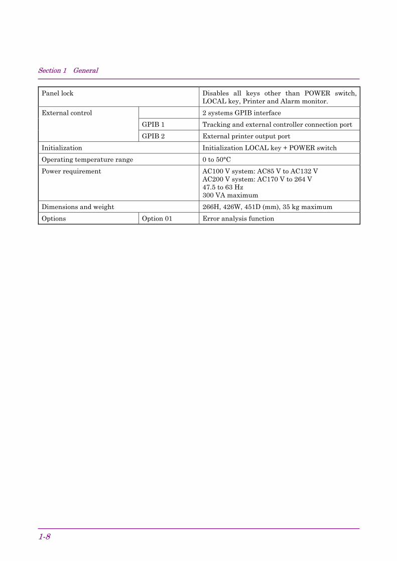
Panel lock Disables all keys other than POWER switch,LOCAL key, Printer and Alarm monitor.
2 systems GPIB interface
GPIB 1 Tracking and external controller connection port
External control
GPIB 2 External printer output port
Initialization Initialization LOCAL key + POWER switch
Operating temperature range 0 to 50°C
Power requirement AC100 V system: AC85 V to AC132 VAC200 V system: AC170 V to 264 V47.5 to 63 Hz300 VA maximum
Dimensions and weight 266H, 426W, 451D (mm), 35 kg maximum
Options Option 01 Error analysis function

1.2 Functions
1-9
Table 1.2-1 Rear Panel FUNCTION DIP Switch Settings
[1] FUNCTION SW 1
SettingSW Function
0 11 Number of mark ratio AND bit shifts 1 bit 3 bit2 Clock loss processing OFF ON3 Sync loss processing OFF ON4 Error performance threshold selection 10−3 10−4
5 Burst measurement OFF ON6 Intermediate data calculation OFF ON78 Error detection mode selection *1 *1
910 Measurement interval time selection *2 *2
*1) SW7 SW80 0 : Total error0 1 : Insertion error1 0 : Omission error1 1 : Total error
*2) SW9 SW100 0 : 1 msec0 1 : 10 msec1 0 : 100 msec1 1 : 1 sec

Section 1 General
1-10
[2] FUNCTION SW 2
SettingSW Function
0 11 Data printing format Standard Abbreviated
2 Threshold EI, EFI data printing functionselection OFF ON
3 Error performance data printingselection OFF ON
4 Intermediate data printing selection OFF ON5 1 second data printing selection OFF ON67
1 second data printing thresholdselection *3 *3
8 Paper saving OFF ON9 Current data interval 100 ms 200 ms
10 FD format switching *4 *4
*3) SW6 SW70 0 : 00 1 : 10−6
1 0 : 10−4
1 1 : 10−3
*4) Refer to table 1.2-2.
Table 1.2-2 2HD
Type Sector length[bytes/sector]
Number ofsectors
[sectors/track]
Number oftracks
[tracks/side]
Numberof sides
SW2BIT 10
1440 KB 512 18 80 2 0
1.3 Composition
1-11
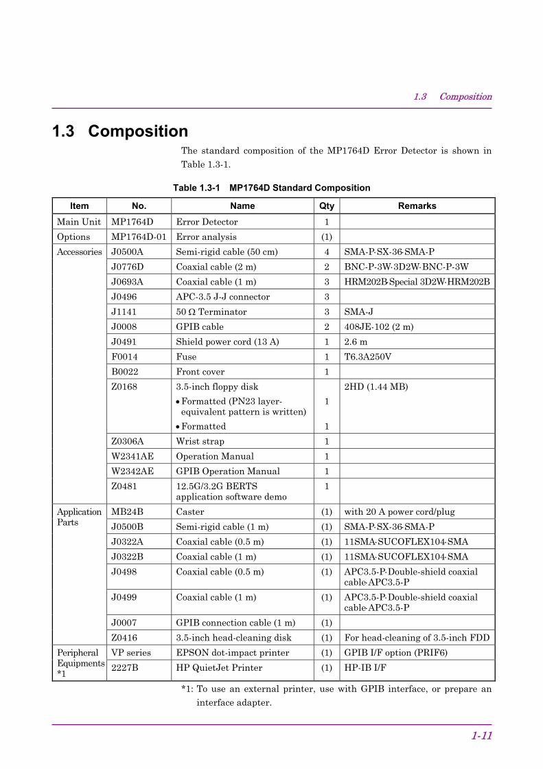
1.3 CompositionThe standard composition of the MP1764D Error Detector is shown in
Table 1.3-1.
Table 1.3-1 MP1764D Standard Composition
Item No. Name Qty Remarks
Main Unit MP1764D Error Detector 1
Options MP1764D-01 Error analysis (1)
J0500A Semi-rigid cable (50 cm) 4 SMA-P⋅SX-36⋅SMA-P
J0776D Coaxial cable (2 m) 2 BNC-P-3W⋅3D2W⋅BNC-P-3W
J0693A Coaxial cable (1 m) 3 HRM202B⋅Special 3D2W⋅HRM202B
J0496 APC-3.5 J-J connector 3
J1141 50 Ω Terminator 3 SMA-J
J0008 GPIB cable 2 408JE-102 (2 m)
J0491 Shield power cord (13 A) 1 2.6 m
F0014 Fuse 1 T6.3A250V
B0022 Front cover 1
Z0168 3.5-inch floppy disk
•Formatted (PN23 layer-equivalent pattern is written)
•Formatted
1
1
2HD (1.44 MB)
Z0306A Wrist strap 1
W2341AE Operation Manual 1
W2342AE GPIB Operation Manual 1
Accessories
Z0481 12.5G/3.2G BERTSapplication software demo
1
MB24B Caster (1) with 20 A power cord/plug
J0500B Semi-rigid cable (1 m) (1) SMA-P⋅SX-36⋅SMA-P
J0322A Coaxial cable (0.5 m) (1) 11SMA⋅SUCOFLEX104⋅SMA
J0322B Coaxial cable (1 m) (1) 11SMA⋅SUCOFLEX104⋅SMA
J0498 Coaxial cable (0.5 m) (1) APC3.5-P⋅Double-shield coaxialcable⋅APC3.5-P
J0499 Coaxial cable (1 m) (1) APC3.5-P⋅Double-shield coaxialcable⋅APC3.5-P
J0007 GPIB connection cable (1 m) (1)
ApplicationParts
Z0416 3.5-inch head-cleaning disk (1) For head-cleaning of 3.5-inch FDD
VP series EPSON dot-impact printer (1) GPIB I/F option (PRIF6)PeripheralEquipments*1
2227B HP QuietJet Printer (1) HP-IB I/F
*1: To use an external printer, use with GPIB interface, or prepare aninterface adapter.

Section 1 General
1-12.

Section 2 Preparations
2-1
2.1 Installation Site Environment ..................................... 2-22.2 Safety Measures........................................................ 2-32.3 Power Supply Voltage ............................................... 2-42.4 Destruction Prevention Measures ............................. 2-5

Section 2 Preparations
2-2
2.1 Installation Site EnvironmentDo not use the instrument in locations:
• Where vibrations are severe.
• Where it is damp or dusty.
• Where there is exposure to direct sunlight.
• Where there is exposure to active gases.
Long-term storage at high temperatures will shorten the life of the inter-nal battery. Store the instrument at normal room temperature.
Operating temperature and humidity conditions 0 to 50 °C,Relative humidity ≤95 %.
Storage temperature and humidity conditions –20 to 60 °C,
Relative humidity ≤95 %.
2.2 Safety Measures
2-3
2.2 Safety Measures• Use the power cord to connect the ac power supply. Ground the
ground terminal of the power cord or the frame ground terminal on therear panel of the instrument.
• When changing the fuse, always use a fuse of the same rating. (See thefuse replacement section.)
• If the instrument is operated at room temperature after being used orstored for a long time at low temperature, condensation may occur andcause short-circuiting. To prevent this, do not turn the power on untilthe instrument is completely dry.

Section 2 Preparations
2-4
2.3 Power Supply VoltageThe power supply voltage for this instrument is shown on the rear panel.Use a voltage within the rated voltage range. Excessive voltage may
damage the circuits.
2.4 Destruction Prevention Measures
2-5
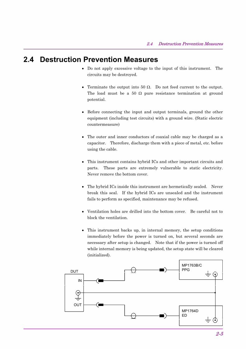
2.4 Destruction Prevention Measures• Do not apply excessive voltage to the input of this instrument. The
circuits may be destroyed.
• Terminate the output into 50 Ω. Do not feed current to the output.The load must be a 50 Ω pure resistance termination at groundpotential.
• Before connecting the input and output terminals, ground the otherequipment (including test circuits) with a ground wire. (Static electriccountermeasure)
• The outer and inner conductors of coaxial cable may be charged as acapacitor. Therefore, discharge them with a piece of metal, etc. beforeusing the cable.
• This instrument contains hybrid ICs and other important circuits andparts. These parts are extremely vulnerable to static electricity.Never remove the bottom cover.
• The hybrid ICs inside this instrument are hermetically sealed. Neverbreak this seal. If the hybrid ICs are unsealed and the instrumentfails to perform as specified, maintenance may be refused.
• Ventilation holes are drilled into the bottom cover. Be careful not toblock the ventilation.
• This instrument backs up, in internal memory, the setup conditionsimmediately before the power is turned on, but several seconds arenecessary after setup is changed. Note that if the power is turned offwhile internal memory is being updated, the setup state will be cleared(initialized).
DUT
IN
OUT
MP1763B/CPPG
MP1764DED

Section 2 Preparations
2-6.

Section 3 Description of Panels and Connectors
3-1
3.1 Front Panel ................................................................ 3-23.2 Rear Panel ................................................................. 3-4

Section 3 Description of Panels and Connectors
3-2
3.1 Front Panel
[14]
[15]
[13][12][11][10][9][8][7][6][5][4][3][2][1]
[19]
[18] [17] [16]
Fig. 3.1-1 Front Panel
No. Name Function and operation[1] POWER switch LED lights with the power turned on.[2] LOCAL key Switches from GPIB REMOTE state (LED lit) to LOCAL key enabled
state. In the GPIB REMOTE state, all the keys other than thePOWER switch and LOCAL key are disabled.
[3] Panel lock key At panel lock (LED lit), all the keys other than the following keys aredisabled.
POWER, PANEL LOCK, PRINTER, ALARM MONITOR[4] TERM CONDITION
keySelects the data-input terminating state.
SINGLE-ENDED/50 Ω: 50 Ω/GND or −2 VDIFFERENTIAL/100 Ω: Differential data input, 100 Ω termination
across the DATA and DATA inputs[5] DATA INPUT DATA signal input connector[6] DATA INPUT DATA signal input connector

3.1 Front Panel
3-3
No. Name Function and operation[7] CLOCK INPUT CLOCK signal input connector, Impedance 50 Ω[8] MONITOR CLOCK
OUTPUTClock Recovery Output connector, Impedance 50 Ω, Output amplitude1.0 Vp-p
[9] Sync output selectorkey
Selects the type of sync level 0/−1 V.1/32 CLOCK: Outputs clock divided by 1/32.FIXED POSITION: Output sync pulse at fixed position relative
to output pattern.VARIABLE POSITION: Shifts sync pulse output position in 16-bit
unit.[10] Sync output connector Impedance 50 Ω, output level 0/−1 V[11] Printer output Turns the printer output on and off. When the switch is on, the lamp
blinks at the end of paper and when off-line.Press “MANUAL PRINT” key when printing intermediatemeasurement data. Enabled only when the printer switch is on.
[12] ERRORS key When the audible alarm sounds at error detection, the key is turned on.When the key is on, the LED inside the key lights.
[13] ALARM key When the audible alarm sounds at alarm detection, the key is turnedon. When the key is on, the LED inside the key lights.
[14] Variable resistor Adjust the volume of the audible alarm. Turning clockwise allows thevolume to be large and counterclockwise to be small.
[15] Speaker Audio alarm speaker[16] Measurement part[17] Pattern setting part[18] Input setting part[19] Floppy setting drive

Section 3 Description of Panels and Connectors
3-4.
3.2 Rear Panel
[13][12][11][10][9][8][7][6][5][4][3][2][1] [14] [15]
Name plate
Fig. 3.2-1 Rear Panel
No. Name Function and operation[1] GPIB setting part Sets GPIB address and system control ON/OFF.[2] GPIB 1 GPIB1 connector[3] GPIB 2 GPIB2 connector (for printer)[4] Name plate Displays the serial number and option.[5] FUNCTION DIP SWITCH FUNCTION1/FUNCTION2 setting DIP SWITCH[6] ALT A/B INPUT ECL level. Inputs the pattern A/pattern B switching timing in
ALTN mode.[7] RESYNC INPUT 0/−1 V 50 Ω. When LOW level is input, sync loss is generated.[8] ALARM OUTPUT TTL level. Outputs LOW level when an alarm is generated.[9] EXT MEAS GATE INPUT 0/−1 V 50 Ω. Mask at LOW level.[10] FRAME SYNC OUTPUT 0/−1 V 50 Ω[11] ORED ERROR OUTPUT STRETCHED: TTL level. Mask at LOW level.[12] SYNC. GAIN OUTPUT 0/−1 V 50 Ω. Synchronization established at HIGH level.[13] Power inlet[14] FUSE holder[15] Ground terminal Connects to the ground terminal of the instrument connected to this
instrument.

Section 4 Operation
4-1
4.1 Setup.......................................................................... 4-34.1.1 Measurement................................................. 4-4
4.2 Internal Memory Initialization..................................... 4-54.3 Input Conditions Setting............................................. 4-7
4.3.1 Data input termination condition and single-ended/differential setting ............................... 4-8
4.3.2 When both DATA and CLOCK are 50 Ω/GNDtermination..................................................... 4-10
4.3.3 When DATA and CLOCK are both 50 Ω/−2 V (ECL) termination................................. 4-13
4.3.4 Auto search ................................................... 4-144.3.5 EYE MARGIN Measurement......................... 4-154.3.6 Clock recovery............................................... 4-17
4.4 Pattern Setting ........................................................... 4-194.4.1 Logic .............................................................. 4-214.4.2 Alternate pattern setting ................................ 4-214.4.3 Data pattern setting ....................................... 4-234.4.4 Zero substitution pattern setting .................... 4-254.4.5 Pseudo random pattern setting ..................... 4-274.4.6 Bit window setting.......................................... 4-284.4.7 Block window setting ..................................... 4-304.4.8 Sync detection mode..................................... 4-324.4.9 Tracking......................................................... 4-344.4.10 Error analysis (Option 01) ............................. 4-35
4.5 Error Measurement.................................................... 4-374.5.1 ERROR RATIO measurement ...................... 4-394.5.2 ERROR COUNT............................................ 4-414.5.3 ERROR INTERVAL....................................... 4-424.5.4 ERROR FREE INTERVAL ............................ 4-444.5.5 CLOCK FREQUENCY .................................. 4-464.5.6 DISPLAY display ........................................... 4-474.5.7 Measurement mode selection ....................... 4-484.5.8 Measurement start/stop................................. 4-494.5.9 Current data function..................................... 4-504.5.10 AUTO SYNC function.................................... 4-524.5.11 Measurement time setting ............................. 4-564.5.12 Real time setting............................................ 4-574.5.13 Error lamp and alarm lamps .......................... 4-584.5.14 Error detection mode setting ......................... 4-60
4.6 Memory (Floppy Disk)................................................ 4-614.6.1 File save ........................................................ 4-614.6.2 File recall ....................................................... 4-62
Section 4 Operation
4-2
4.6.3 Disk formatting............................................... 4-634.6.4 File delete ...................................................... 4-634.6.5 Error messages ............................................. 4-644.6.6 Floppy disk .................................................... 4-644.6.7 Floppy disk precautions................................. 4-65
4.7 Printer output ............................................................. 4-664.7.1 Printing Format .............................................. 4-69
4.8 Definition of Terms..................................................... 4-734.8.1 Measurement items....................................... 4-734.8.2 Alarm intervals............................................... 4-734.8.3 Threshold EI and EFI data ............................ 4-744.8.4 Error performance data ................................. 4-74
4.9 Processing of Measurement Data at AlarmGeneration ................................................................. 4-77
4.10 FUNCTION Switch Setting ........................................ 4-80

4.1 Setup
4-3
4.1 SetupBe careful of static electricity when handling the MP1764D. Connectionto an MP1763B/C Pulse Pattern Generator is described here as an exam-ple. Refer to the following figure and make the connections in the fol-
lowing order.
MP1764D
MP1763B/CGround wire
Semiriged cable supplied
1. Connect the MP1764D and MP1763B/C ground terminals withground wire.
2. Connect the power cord to an ac outlet. At this time, use a 3-prongplug with ground. If a 2-prong plug must be used, connect theMP1764D and MP1763B/C ground terminals before connecting theplug to the socket.
3. While pressing the LOCAL key, turn on the power and initialize theMP1764D and MP1763B/C. When initialization is performed, allthe settings are set to the factory settings. (See Table 4.2-1.) Whensetting a pattern, etc. that you do not want to clear, save it to FD.(See 4.6.1.) Initialization makes the MP1764D and MP1763B/C set-tings the same. Turn off the power.
CAUTION If a high voltage is applied to the input connector, theprotection circuit may be damaged. Never apply an inputexceeding the rating. If the rating may be exceeded,check the input signal before making any connections.

Section 4 Operation
4-4
4.1.1 Measurement1. Check that the MP1764D Error Detector and MP1763B/C Pulse Pat-
tern Generator settings are the same. Since the instruments wereinitialized in Section 4.1, the settings should be the same. If the set-tings are different, initialize the instruments again. Then, set theMP1763B/C OUTPUT and the MP1764D AUTO SYNC and STARTkey to ON.
2. Press the MP1764D AUTO SEARCH key. The input data thresholdvoltage and input clock delay time are automatically set.
After the AUTO SEARCH lamp goes off, check that the CLOCKLOSS, SYNC LOSS, and ERRORS real time lamps are not lit. If thelamps are lit, check that signaling cables are connected correctly.
AUTO SEARCH key
3. Change the DISPLAY display item and check if the following meas-ured result is obtained:
ERROR RATIO: Error ratio displayedERROR COUNT: Error count displayedERROR INTERVAL: Number of error intervals (See 4.8.1.)ERROR FREE INTERVAL:Number of error free intervals ratio
(See 4.8.1.)
4. Add an error and check if it is correctly detected.
Set MP1763B/C ERROR ADDITION to ON and select 1×10⁻⁶.
Select ERROR RATIO at MP1764D DISPLAY and check if 1×10⁻⁶ isdisplayed at DISPLAY.
4.2 Internal Memory Initialization
4-5
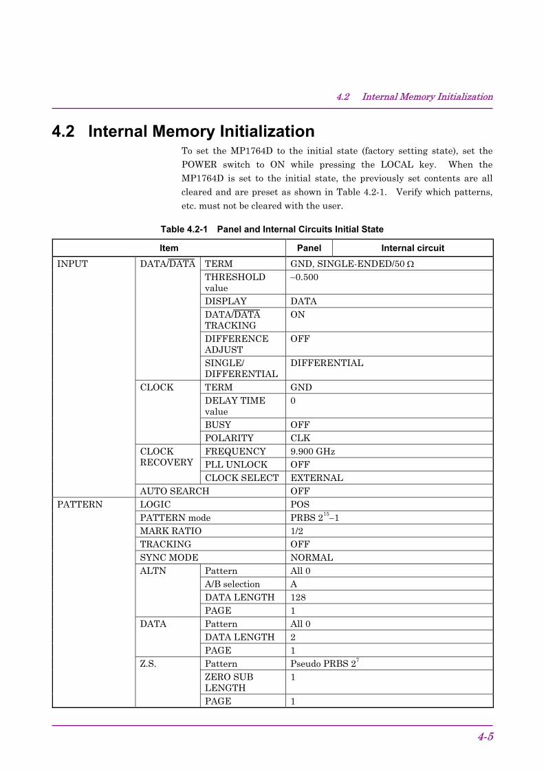
4.2 Internal Memory InitializationTo set the MP1764D to the initial state (factory setting state), set thePOWER switch to ON while pressing the LOCAL key. When theMP1764D is set to the initial state, the previously set contents are allcleared and are preset as shown in Table 4.2-1. Verify which patterns,
etc. must not be cleared with the user.
Table 4.2-1 Panel and Internal Circuits Initial State
Item Panel Internal circuitTERM GND, SINGLE-ENDED/50 ΩTHRESHOLDvalue
−0.500
DISPLAY DATADATA/DATATRACKING
ON
DIFFERENCEADJUST
OFF
DATA/DATA
SINGLE/DIFFERENTIAL
DIFFERENTIAL
TERM GNDDELAY TIMEvalue
0
BUSY OFF
CLOCK
POLARITY CLKFREQUENCY 9.900 GHzPLL UNLOCK OFF
CLOCKRECOVERY
CLOCK SELECT EXTERNAL
INPUT
AUTO SEARCH OFFLOGIC POSPATTERN mode PRBS 215−1MARK RATIO 1/2TRACKING OFFSYNC MODE NORMAL
Pattern All 0A/B selection ADATA LENGTH 128
ALTN
PAGE 1Pattern All 0DATA LENGTH 2
DATA
PAGE 1Pattern Pseudo PRBS 27
ZERO SUBLENGTH
1
PATTERN
Z.S.
PAGE 1
Section 4 Operation
4-6
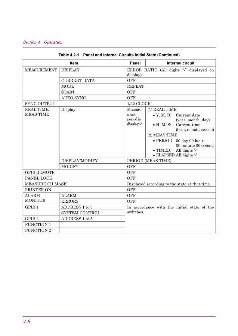
Table 4.2-1 Panel and Internal Circuits Initial State (Continued)
Item Panel Internal circuitDISPLAY ERROR RATIO (All digits “-” displayed on
display)CURRENT DATA OFFMODE REPEATSTART OFF
MEASUREMENT
AUTO SYNC OFFSYNC OUTPUT 1/32 CLOCK
Display Measure-mentperiod isdisplayed.
(1) REAL TIME• Y. M. D: Current date
(year, month, day)• H. M. S: Current time
(hour, minute, second)(2) MEAS TIME
• PERIOD: 00 day 00 hour00 minute 00 second
• TIMED: All digits ‘-’• ELAPSED:All digits ‘-’
DISPLAY/MODIFY PERIOD (MEAS TIME)
REAL TIME/MEAS TIME
MODIFY OFFGPIB REMOTE OFFPANEL LOCK OFFMEASURE CH MASK Displayed according to the state at that time.PRINTER ON OFF
ALARM OFFALARMMONITOR ERRORS OFF
ADDRESS 1 to 5GPIB 1SYSTEM CONTROL
GPIB 2 ADDRESS 1 to 5FUNCTION 1FUNCTION 2
In accordance with the initial state of theswitches.

4.3 Input Conditions Setting
4-7
4.3 Input Conditions Setting
[1]
[2]
[3]
[4]
[5]
[12]
[13]
[11]
[6] [7] [8] [9] [10]
[16] [15] [14]
No. Name Function and operation[1] DISPLAY key Switches the display of DATA, DATA input threshold setting value.
The LED inside the key lights in DATA input display state.[2] TERM key Selects the DATA input termination condition. Switches while
pressing the GUARD key.[3] Rotary encoder (DATA) Sets data input threshold value.[4] PLL RESET key Resets the PLL in the Clock Recovery circuit.[5] CLOCK SELECT key Selects the clock for measurements, EXTERNAL or RECOVERY.[6] AUTO SEARCH key Performs AUTO SEARCH.[7] EYE MARGIN ON Sets the EYE margin measurement mode.[8] EYE MARGIN START Starts the EYE margin measurement.[9] POLARITY key Inverts the CLOCK polarity.[10] EYE MARGIN
keySelects the EYE margin measurement.
[11] Rotary encoder Sets the Clock Recovery frequency.[12] TERM key Selects the CLOCK input termination condition. Switches while
pressing the GUARD key.[13] Rotary encoder (CLOCK) Adjusts clock-input phase.[14] SINGL-ENDED/
DIFFERENTIAL keySets the data input condition to SINGL-ENDED/DIFFERENTIAL.
[15] DIFFERENCE ADJUST Displays and adjusts the voltage difference of DATA, DATAthreshold value when the LED inside the key lights.
[16] DATA/DATATRACKING
Sets the threshold value of DATA, DATA threshold value to thesame value when the LED inside the key lights.

Section 4 Operation
4-8
4.3.1 Data input termination condition and single-ended/differential set-ting
Set SINGLE-ENDED or DIFFERENTIAL by using the single/differentialswitching key according to the input conditions of the data to be meas-ured.When set to SINGLE-ENDED, the termination condition becomes SIN-GLE-ENDED/50 Ω.When set to DIFFERENTIAL, select SINGLE-ENDED/50 Ω or DIFFER-ENTIAL/100 Ω according to the termination condition by pressing the
termination condition selection key.
Setting of input condition Setting of termination condition
(a) When measuring single-ended data and termination condition is 50Ω/GND (or –2 V)Set whether to use DATA or DATA by using the DISPLAY key. Thenpress the single/differential switching key to set SINGLE-ENDED(termination condition is set to SINGLE-ENDED/50 Ω). Connectthe data input that was selected by the DISPLAY key, and connectthe provided 50-Ω terminator to the unused input connector.The figure below shows an example when measuring single-ended datausing DATA input (connect the 50-Ω terminator to DATA input).
SINGLE/DIFFERENTIAL: SINGLE-ENDEDTERM CONDITION: SINGLE-ENDED/50 ΩDISPLAY: DATA
GND (/−2 V)
DATA INPUT
DATA INPUT
50
50
50
Test Signal
MP1764D
Terminator

4.3 Input Conditions Setting
4-9
(b) When measuring differential data and termination condition is 50 Ω/GND(or –2 V)Press the single/differential switching key to set DIFFERENTIAL.Then press the termination condition selection key to set SINGLE-ENDED/50 Ω. Connect the differential data to be measured to DATAand DATA input.
SINGLE/DIFFERENTIAL: DIFFERENTIALTERM CONDITION: SINGLE-ENDED/50 ΩDISPLAY: (arbitrary)
GND (/−2 V)
DATA INPUT
DATA INPUT
50
50
MP1764D
Test Signal
Test Signal
(c) When measuring differential data and termination condition is 100 Ωbetween DATA and DATA (LVDS, etc.)Press the single/differential switching key to set DIFFERENTIAL.Then press the termination condition selection key to set DIFFER-ENTIAL/100 Ω.The two data inputs are terminated by 100 Ω resistance as shown inthe figure below.
SINGLE/DIFFERENTIAL: DIFFERENTIALTERM CONDITION: DIFFERENTIAL/100 ΩDISPLAY: (arbitrary)
DATA INPUT
DATA INPUT
50
50
MP1764D
Test Signal
Test Signal
open
GND (/−2 V)
Section 4 Operation
4-10
4.3.2 When both DATA and CLOCK are 50 Ω/GND termination
[3]
[2] [1]
[4]
[5]
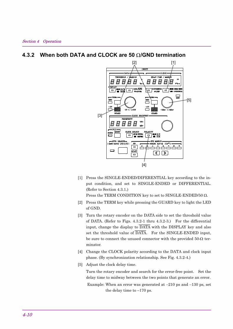
[1] Press the SINGLE-ENDED/DIFERENTIAL key according to the in-put condition, and set to SINGLE-ENDED or DIFFERENTIAL.(Refer to Section 4.3.1.)Press the TERM CONDITION key to set to SINGLE-ENDED/50 Ω.
[2] Press the TERM key while pressing the GUARD key to light the LEDof GND.
[3] Turn the rotary encoder on the DATA side to set the threshold valueof DATA. (Refer to Figs. 4.3.2-1 thru 4.3.2-3.) For the differentialinput, change the display to DATA with the DISPLAY key and alsoset the threshold value of DATA. For the SINGLE-ENDED input,be sure to connect the unused connector with the provided 50-Ω ter-minator.
[4] Change the CLOCK polarity according to the DATA and clock inputphase. (By synchronization relationship. See Fig. 4.3.2-4.)
[5] Adjust the clock delay time.
Turn the rotary encoder and search for the error-free point. Set thedelay time to midway between the two points that generate an error.
Example: When an error was generated at –210 ps and –130 ps, setthe delay time to –170 ps.

4.3 Input Conditions Setting
4-11
CAUTION • When measuring single-ended input data, connect the
provided 50-Ω terminator to the unused data inputconnector. If the unused data input connector is open,measurement may not be performed accurately.
• The value of displayed delay time is not absolute delaytime of clock input for the data input. Use as astandard when the magnitude of clock phase change iscalculated or the clock phase is adjusted.
• When amplitude and offset voltage known
Offset voltage (VOH)
Amplitude (Vp-p) Threshold voltage=VOH−Vp-p
2
Fig. 4.3.2-1
• When high level and low level known
High level (VOH)
Low level (VOL)
Threshold voltage= VOH+VOL
2
Fig. 4.3.2-2

Section 4 Operation
4-12
Setting the optimum valueIn the error free state, lower the DATA threshold voltage and measurethe voltage that generates an error (V1). Then raise the threshold volt-age and measure the voltage that generates an error (V2). Set the
threshold voltage to midway between these two voltages. V1+V2
2
V2
V1
V1+V2
2
Fig. 4.3.2-3
Next, move CLOCK Delay in the minus direction and measure the phase(D1) that generates an error. Then move CLOCK Delay in the plus direc-tion and measure the phase (D2) that generates an error. Set theCLOCK Delay to midway between these two values.
D1+D2
2
D1 D2
Fig. 4.3.2-4

4.3 Input Conditions Setting
4-13
4.3.3 When DATA and CLOCK are both 50 Ω/−2 V (ECL) termination
[3]
[2] [1]
[1] Press the single/differential switching key to set SINGLE-ENDED orDIFFERENTIAL according to the input conditions. (Refer to Section4.3.1.)Then press the termination condition selection key to set SINGLE-ENDED/50 Ω.
[2] While pressing the GUARD key, press the –2 V key. The –2 V LEDlights.
[3] Set the DATA threshold voltage to –1.3 V (standard center voltage ofECL). For differential input, switch the display to DATA by usingthe DISPLAY switching key to set the DATA threshold value. Forsingle-ended input, be sure to connect the provided 50-Ω terminatorto the unused connector.
[4] Set the CLOCK phase, etc. as described in Section 4.3.2.
CAUTION Incorrect setting of the termination voltage may damagethe device under test. Be very careful when changing thesetting.When measuring single-ended input data, connect theprovided 50-Ω terminator to the unused data inputconnector. If the unused data input connector is open,measurement cannot be performed accurately.
Section 4 Operation
4-14
4.3.4 Auto search
[1]
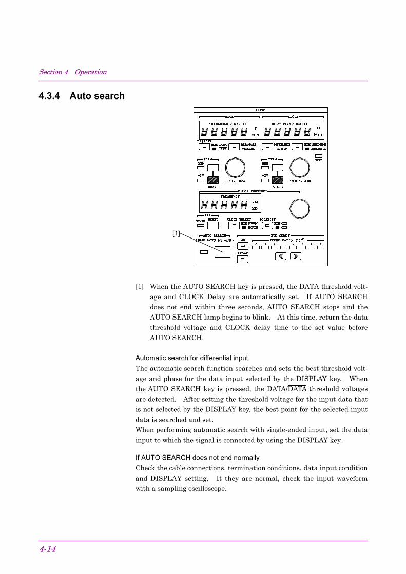
[1] When the AUTO SEARCH key is pressed, the DATA threshold volt-age and CLOCK Delay are automatically set. If AUTO SEARCHdoes not end within three seconds, AUTO SEARCH stops and theAUTO SEARCH lamp begins to blink. At this time, return the datathreshold voltage and CLOCK delay time to the set value beforeAUTO SEARCH.
Automatic search for differential inputThe automatic search function searches and sets the best threshold volt-age and phase for the data input selected by the DISPLAY key. Whenthe AUTO SEARCH key is pressed, the DATA/DATA threshold voltagesare detected. After setting the threshold voltage for the input data thatis not selected by the DISPLAY key, the best point for the selected inputdata is searched and set.When performing automatic search with single-ended input, set the data
input to which the signal is connected by using the DISPLAY key.
If AUTO SEARCH does not end normallyCheck the cable connections, termination conditions, data input conditionand DISPLAY setting. It they are normal, check the input waveformwith a sampling oscilloscope.

4.3 Input Conditions Setting
4-15
4.3.5 EYE MARGIN Measurement
[1] [2] [3]
[1] Press the ON key. The LED inside the key lights. At this time,
Vp-p ps p-p
is displayed.
[2] Set the threshold value error rate.
[3] Start measurement by pressing the START key. At the end ofmeasurement, the measured result is displayed on the display.
EYE MARGIN starts measurement from the point (point A) obtained byAUTO SEARCH. Therefore, measurements are made within the range
shown below.
Phase margin(PSp-p)
Bias margin(Vp-p)
ABB
B
B
Point B is the position (10−2 to 10−9) delayed by the threshold value setERROR RATIO.

Section 4 Operation
4-16
EYE MARGIN measurement for differential inputAutomatic search for differential input is performed (refer to Section4.4.4), and then EYE MARGIN measurement is performed for the inputdata set by the DISPLAY key in the same way as single-ended input.For differential input, however, measurement is performed for the differ-ential data of two inputs, unlike in the case of the single-ended input ran-ge as shown in the figure below. The bias margin result thus becomes
double that when measuring the same signal with single-ended input.
A
V (DATA)
V (DATA)
V (DATA) - V (DATA)
A
V (DIFFERENTIAL)
4.3 Input Conditions Setting
4-17
4.3.6 Clock recovery
[3] [1] [2]
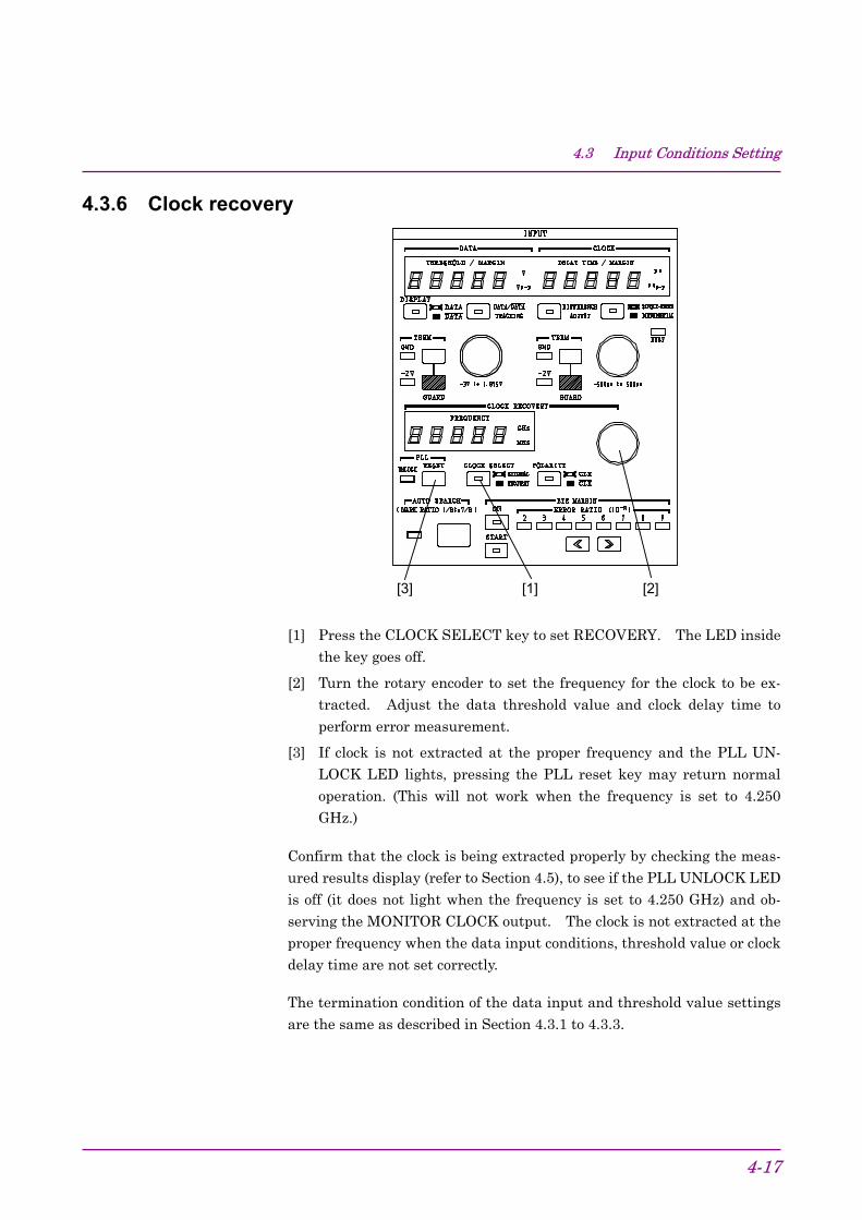
[1] Press the CLOCK SELECT key to set RECOVERY. The LED insidethe key goes off.
[2] Turn the rotary encoder to set the frequency for the clock to be ex-tracted. Adjust the data threshold value and clock delay time toperform error measurement.
[3] If clock is not extracted at the proper frequency and the PLL UN-LOCK LED lights, pressing the PLL reset key may return normaloperation. (This will not work when the frequency is set to 4.250
GHz.)
Confirm that the clock is being extracted properly by checking the meas-ured results display (refer to Section 4.5), to see if the PLL UNLOCK LEDis off (it does not light when the frequency is set to 4.250 GHz) and ob-serving the MONITOR CLOCK output. The clock is not extracted at theproper frequency when the data input conditions, threshold value or clockdelay time are not set correctly.
The termination condition of the data input and threshold value settingsare the same as described in Section 4.3.1 to 4.3.3.

Section 4 Operation
4-18
CAUTION • When RECOVERY is set by the clock selection key,
clock input becomes an open circuit. SettingRECOVERY while a signal is connected to the clockinput may damage the clock signal source dependingon the termination condition.
• The monitor clock output is assist-output to check theclock recovery function.

4.4 Pattern Setting
4-19
4.4 Pattern Setting
[1]
[3]
[2]
[4]
[5] [6] [7] [8]
[9]
[10]
[11]
[12]
[13]
[14] [15][16][17]
No. Name Function and operation[1] LOGIC Inverts the DATA/DATA output logic. The DATA output logic is
shown by lightning of the POS or NEG lamp.[2] SYNC MODE Selects the sync pull-in mode. One of the following three modes can
be selected:NORMAL: Turn on normal sync pull-in.FRAME: Turn on the frame sync function.QUICK: Turn on the quick sync function.
[3] FRAME LENGTH Sets the frame pattern bit length at FRAME SYNC.

Section 4 Operation
4-20
No. Name Function and operation[4] BIT setting keys Set the logic of each bit for each Page. When LOGIC is POS,
lightning of the lamp above each key indicates logic ‘1.’[5] ALL edit keys Sets all the bits of the selected pattern to logic ‘0’ or ‘1.’ Press the 0
or 1 key while pressing the GUARD key.[6] PAGE edit keys Sets all bits of the displayed page to ‘0’ or ‘1.’[7] ERROR ANALYSIS
(OPTION 01)Turns the error analysis function on and off. Lightning of the lampshows that the error analysis function is ‘ON.’ This function isenabled only when OPTION 01 is built-in.
[8] TRACKING Turns the tracking function on and off. Lightning of the lampinside the key shows that the tracking function is ‘On.’
[9] BLOCK WINDOW Turned on when error measurement in block units (32 bits) ismasked.
[10] BIT WINDOW Turned on when error measurement in channel units (1 unit) ismasked. (All 32 channels)
[11] keys
Sets the page and the pattern sync output position.
[12] keys
Sets the data length and number of consecutive zeros in Z.S.
[13] ALTN keys Selects the A/B pattern at ALTN pattern setting.[14] DISPLAY SELECT Selects the item displayed on the display. When PATT, BIT
WINDOW, and BLOCK WINDOW are set, that item is selected andset at the panel. (It is possible to select ERROR ANALYSIS whenOPTION 01 is built-in.
[15] MARK ratio selectionkeys
Set the receive pattern mark ratio for PRBS.
[16] PRBS/ZERO SUBSTkeys
Set the PRBS or pseudo PRBS period.
[17] PATTERN selection keys Selects the type of receive pattern.[18] DISPLAY key Toggles the display between PAGE and PATTERN SYNC
POSITION.
4.4 Pattern Setting
4-21
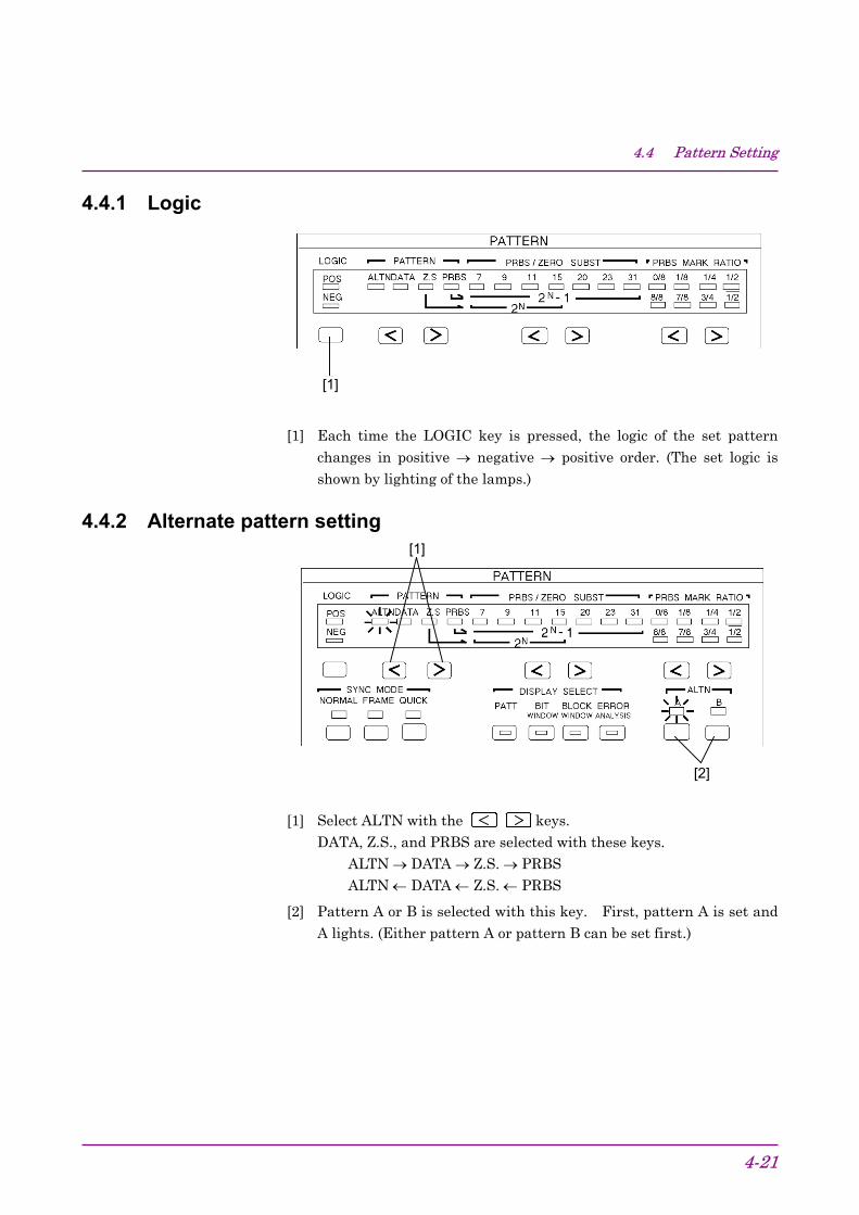
4.4.1 Logic
①[1]
[1] Each time the LOGIC key is pressed, the logic of the set patternchanges in positive → negative → positive order. (The set logic isshown by lighting of the lamps.)
4.4.2 Alternate pattern setting
[2]
[1]
[1] Select ALTN with the keys.DATA, Z.S., and PRBS are selected with these keys.
ALTN → DATA → Z.S. → PRBSALTN ← DATA ← Z.S. ← PRBS
[2] Pattern A or B is selected with this key. First, pattern A is set andA lights. (Either pattern A or pattern B can be set first.)

Section 4 Operation
4-22
[3]
[3] Set DATA LENGTH with the and keys.This value is common to both patterns A and B.
Select the digit to be set with the keys.
Set DATA LENGTH with the keys.Set value: 128 to 4194304 bits (128 bit steps)
Change the BIT value with the button below the LED. When LOGIC ispositive, lighting of the LED indicates High Level.
When you want to change all the DATA at once, use PRESET ALL orPAGE.
PAGE 0 or 1: All BIT of the displayed PAGE become 0 or 1.
ALL 0 or 1: Each time the 0 or 1 key is pressed while pressing theGUARD key, all BIT specified by DATA LENGTH become‘0’ or ‘1’.
Next, set [2] to pattern B (B LED lights) and set pattern B the same as
pattern A.
However, since DATA LENGTH is common to patterns A and B, do notchange it here. If it is changed, the pattern A DATA LENGTH changesalso.
Two patterns (pattern A and pattern B) can be set. The number of re-petitions of each pattern is controlled by ALTN A/B INPUT (rear panel).(Connected to the MP1763B/C)
4.4 Pattern Setting
4-23
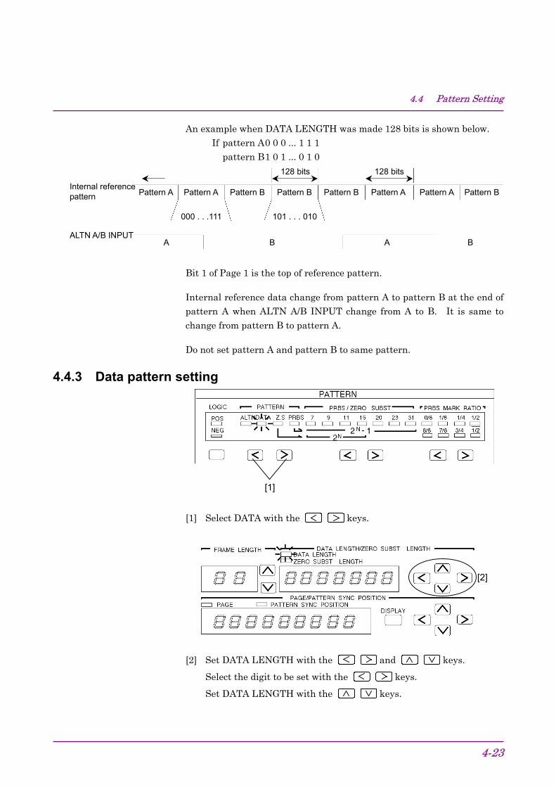
An example when DATA LENGTH was made 128 bits is shown below.If pattern A0 0 0 ... 1 1 1
pattern B1 0 1 ... 0 1 0
Internal referencepattern
A A BB
Pattern A Pattern A Pattern B Pattern B Pattern APattern B Pattern A Pattern B
ALTN A/B INPUT
128 bits 128 bits
000 . . .111 101 . . . 010
Bit 1 of Page 1 is the top of reference pattern.
Internal reference data change from pattern A to pattern B at the end ofpattern A when ALTN A/B INPUT change from A to B. It is same to
change from pattern B to pattern A.
Do not set pattern A and pattern B to same pattern.
4.4.3 Data pattern setting
[1]
[1] Select DATA with the keys.
[2]
[2] Set DATA LENGTH with the and keys.
Select the digit to be set with the keys.
Set DATA LENGTH with the keys.

Section 4 Operation
4-24
DATA LENGTH setting step2 to 65536: STEP 1 bit65536 to 131012: STEP 2 bitsThereafter refer to Section 1.2 “Functions.”
First set the page displayed at the bottom BIT display, with the set DATALENGTH as 16 bits/page. BIT of the displayed page can be changed.
Set value: 1 to (DATA LENGTH/16)(LENGTH is multiple of 16)1 to INT (DATA LENGTH/16) +1(LENGTH is not multiple of 16)
Change the BIT value with the button below the LED. When LOGIC is
positive, lighting of the LED indicates High level.
When you want to change all the DATA at once, use PRESET ALL orPAGE.
PAGE 0 or 1: All BIT of the displayed PAGE become 0 or 1.
ALL 0 or 1: All BIT specified by DATA LENGTH become ‘0’ or ‘1’ eachtime the ‘0’ or ‘1’ key is pressed while pressing the GUARDKEY.

4.4 Pattern Setting
4-25
An arbitrary pattern is repeated as reference pattern.
When a 16 bits pattern was set:
Set pattern “0 0 0 0 0 1 0 1 1 1 1 1 1 0 1 0”
← ←
1 1 1 0 1 0 0 0 0 0 0 1 0 1 1 1 1 1 1 0 1 0 0 0 0 0 0 1 0 1
4.4.4 Zero substitution pattern setting
[1]
[1] Select Z.S. with the keys.
[2]
[2] Set 2N pattern with the keys. (This pattern is pseudo PRBSwith a 2N period.)
Section 4 Operation
4-26
[3]
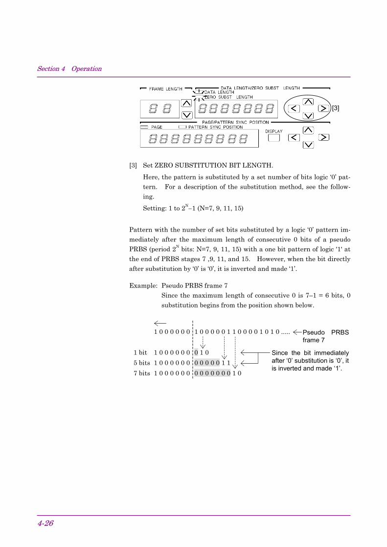
[3] Set ZERO SUBSTITUTION BIT LENGTH.
Here, the pattern is substituted by a set number of bits logic ‘0’ pat-tern. For a description of the substitution method, see the follow-ing.
Setting: 1 to 2N−1 (N=7, 9, 11, 15)
Pattern with the number of set bits substituted by a logic ‘0’ pattern im-mediately after the maximum length of consecutive 0 bits of a pseudoPRBS (period 2N bits: N=7, 9, 11, 15) with a one bit pattern of logic '1' atthe end of PRBS stages 7 ,9, 11, and 15. However, when the bit directlyafter substitution by ‘0’ is ‘0’, it is inverted and made ‘1’.
Example: Pseudo PRBS frame 7Since the maximum length of consecutive 0 is 7–1 = 6 bits, 0
substitution begins from the position shown below.
1 0 0 0 0 0 0 1 0 0 0 0 0 1 1 0 0 0 0 1 0 1 0 .....
1 bit 1 0 0 0 0 0 0 0 1 0
5 bits 1 0 0 0 0 0 0 0 0 0 0 0 1 1
7 bits 1 0 0 0 0 0 0 0 0 0 0 0 0 0 1 0
Since the bit immediatelyafter ‘0’ substitution is ‘0’, itis inverted and made ‘1’.
Pseudo PRBSframe 7

4.4 Pattern Setting
4-27
4.4.5 Pseudo random pattern setting
[1]
[1] Select PRBS with the keys.
[2] [3]
[2] Set the number of PRBS frames with the keys.
[3] Set the PRBS mark ratio with the keys.
When LOGIC is positive, make your selection from the top row (0/8,1/8, 1/4, 1/2).
When LOGIC is negative, make your selection from the bottom row(8/8, 7/8, 3/4, 1/2).
When LOGIC is changed from positive to negative when mark ratio is 1/4,the mark ratio changes to 3/4.
Pattern generated by the principle described in Section “5.1 Pseudo ran-dom Pattern.” When arbitrary consecutive N bits was selected in the bitarray of a PRBS pattern having a period of 2N–1, the same bit array doesnot exist in one period. That is, all bit arrays can be considered otherthan ‘0’ in one period.
Note:When setting pseudo random pattern, the BIT LEDs light accord-
ing to the set pattern.

Section 4 Operation
4-28
4.4.6 Bit window settingThis setting masks the 32 error counters in the MP1764D.
[2]
[1]
[1] Press the BIT WINDOW key of DISPLAY SELECT to light the LEDinside the key.
[2] PAGE is displayed. The PAGE number is 1 to 2.
[3] Select the channel for which the error counter is to be masked.Masked when the LED lights.
[4] To actually execute the BIT WINDOW function, press the BIT WIN-DOW key to light the LED inside the key.

4.4 Pattern Setting
4-29
[3] [4]
The relationship between the bits selected in [3] and the 32 errorcounters is as follows:
PAGE 1, BIT 1 → Error counter number 1PAGE 1, BIT 2 → Error counter number 2
: : :PAGE 1, BIT 16 → Error counter number 16PAGE 2, BIT 1 → Error counter number 17PAGE 2, BIT 2 → Error counter number 18
: :PAGE 2, BIT 16 → Error counter number 32
The bit window function masks the error counters in the MP1764D.
Error counter
Error counter
Error counter
Error counter
1
2
31
32
The 32 error counters detect errors in the order of set pattern bits for pro-grammable patterns (zero substitution, DATA, and alternate). For ex-ample, for 32 bit long DATA patterns:
Error counters 1 2 3 4 30 31 32 1 2
Input signal 1 2 3 4 30 31 32 1 2
This bit window can be combined with the block window (4.4.7) to meas-
ure a 1 bit error in the measurement pattern.
Section 4 Operation
4-30
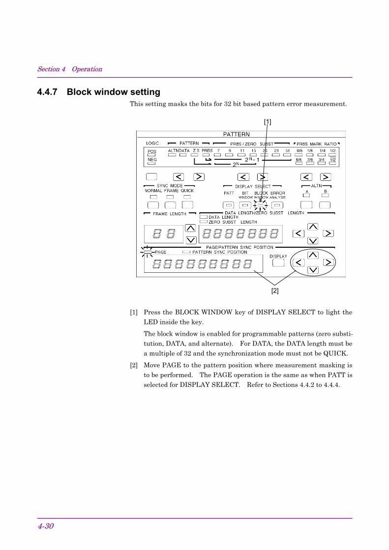
4.4.7 Block window settingThis setting masks the bits for 32 bit based pattern error measurement.
[2]
[1]
[1] Press the BLOCK WINDOW key of DISPLAY SELECT to light theLED inside the key.
The block window is enabled for programmable patterns (zero substi-tution, DATA, and alternate). For DATA, the DATA length must bea multiple of 32 and the synchronization mode must not be QUICK.
[2] Move PAGE to the pattern position where measurement masking isto be performed. The PAGE operation is the same as when PATT isselected for DISPLAY SELECT. Refer to Sections 4.4.2 to 4.4.4.

4.4 Pattern Setting
4-31
[3] [4]
[3] Select a pattern mask on the BIT indicator.
When a LED is on, the bit is masked.
One LED of the BIT indicator indicates one bit in the pattern setting.When one key of the BIT indicator is pressed, the LEDs for all 32 bitsgo on or off together because the block window is turned on or off foreach of the 32 bits.
[4] To actually execute the block window function, press the BLOCKWINDOW key to light the LED inside the key.
The block window function can be used with the bit window function tomeasure errors on one-bit basis. Measurement can be masked by OR op-eration of the bit and block windows.
One cycle
32 bits 32 bits 32 bits 32 bits 32 bits 32 bits Input pattern
Block window
Bit window
1 bit
Only the high-order bit of a pattern can be measured as shown above.

Section 4 Operation
4-32
4.4.8 Sync detection modeThe transmitter generated pattern and receiver pattern synchronizationmethod is selected. Three synchronization methods are available:NORMAL, FRAME, and QUICK. However, the following restrictions
apply:
Table 4.4.8-1 Synchronization Selection Restrictions
SYNC MODEPATTERN
NORMAL FRAME QUICKALTN ×DATA ∆*1
Z.S.PRBS Automatic (Internal Synchronization circuit)
*1 When DATA LENGTH ≥128 bits
Frame sync mode[1] [2]
[1] Select FRAME from SYNC MODE.
[2] Set FRAME LENGTH with the keys.
Set the frame bit from the top of page 1. The set bit which repre-sents logic ‘1’ by orange color.
• The set value is maximum 32 bits/4 bits STEP.
• For ALTN, set the frame bit from the top of pattern A. (Pattern Bis not a frame bit objective.)

4.4 Pattern Setting
4-33
Frame sync mode:
Since synchronization is established by frame bit (maximum 32 bits)
specified at FRAME LENGTH, when the same pattern string as
frame bit exists, synchronization may take some time. The use of aspecial pattern at frame bit is desirable. (All ‘1’, ‘AA’ repetition, etc.)
When testing with data having a long bit length, synchronization can bedetected quickly by the following procedure:
(1) Set the data.(2) Select the frame sync mode and make the frame length 32 bits.(3) Make the contents of the 32 bits a special pattern (All ‘1’, ‘AA’ repeti-
tion, etc.)(4) Establish synchronization by automatic synchronization. (AUTO
SYNC ON)(5) Release automatic synchronization. (AUTO SYNC OFF)(6) Return the changed 32-bit data to its original state.
QUICK sync mode[1]
[1] Select QUICK from SYNC MODE.
QUICK sync mode:
Method that makes error measurements by fetching data of the bit length
set by DATA LENGTH to internal memory and uses the fetched patternas the standard pattern. In this case, the pattern BIT setting is invalid.

Section 4 Operation
4-34
4.4.9 Tracking
[1]
[1] Press the TRACKING key. The LED inside the key lights and theMP1764D enters the tracking mode.
* When tracking is performed, the MP1763B/C must be connectedby GPIB.
When the PATTERN LOADING lamp lights, data is being read andthe keys cannot be operated.
Tracking can be performed from both the receiver and the transmitter.However, one of them must be set as the master. Therefore, trackingcannot be performed simultaneously from both the receiver and thetransmitter.
When performing tracking, set ‘SYSTEM CONTROL’ of the DIP switch onthe rear panel of the master unit to ‘ON’. (Set ‘SYSTEM CONTROL’ of thecontrolled unit to ‘OFF’.)Set GPIB ADDRESS of the controlled unit to master unit GPIB AD-DRESS + 2.
Note:The Dip switch on the rear panel for setting GPIB address is coveredwith the panel and fasten with screws to decrease the radio activeradiation. To change the address, remove the panel for the setting.
Each time the settings of the master unit (receiver or transmitter) arechanged in the tracking ON state, the settings of the transmitter (or re-ceiver) are changed. Therefore, each time a master key is operated, anunavailable state is generated. (Especially, when the program bit length islong, an unavailable state of several tens of seconds is generated.) To pre-vent this, when changing the master unit settings, set tracking to OFF.

4.4 Pattern Setting
4-35
4.4.10 Error analysis (Option 01)At error detection, 256 bits of data are memorized and the error and the
data before and after it can be checked.
[1]
[2]
[1] Press the ERROR ANALYSIS key. The LED inside the key lights.
[2] Change the display page for the ERROR ANALYSIS DATA.
Sixteen pages, including the pattern that generated an error, can beset.
Pages 9 and 10 display the BIT that generated an error and becamethe trigger.
[3]
[3] Set ERROR ANALYSIS TRIGGER to ON.

Section 4 Operation
4-36
Result Display
[5]
[4]
[4] The display page is shown.
Page position shows the pattern setting and display page position.
[5] The error is indicated by a red or orange LED. (See Table 4.4.10-1.)
Table 4.4.10-1
Receive data Reference LED0 0 OFF Normal1 1 Green Normal0 1 Red Insertion error1 0 Orange Omission error
* When performing error analysis using the PRBS 231−1 pattern, a fewseconds after synchronization is established before starting analysis.

4.5 Error Measurement
4-37
4.5 Error Measurement
[1] [3]
[7][8]
[9]
[5][10]
[11] [4]
[6]
[2]
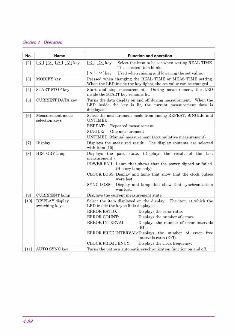
No. Name Function and operation[1] DISPLAY/MODIFY key REAL TIME
Y.M.D Press to set or display the date. When the LED insidethe key lights, the date is displayed on the display.
H.M.S Press to set or display the time. When the LED insidethe key lights, the time is displayed on the display.
MEAS TIMEPERIOD Press to set or display the measurement time
(gating time). When the LED inside the key lights,the measurement time (gating time) is displayed onthe display.
TIME Press to display the remaining measurement time.When the LED inside the key lights, the remainingtime is displayed on the display. Cannot be selectedwhen the measurement mode is UNTIMED.
ELAPSED Press to display the elapsed measurement time.When the LED inside the key lights, the elapsedtime is displayed on the display.
Section 4 Operation
4-38
No. Name Function and operation[2] key key Select the item to be set when setting REAL TIME.
The selected item blinks. key Used when raising and lowering the set value.
[3] MODIFY key Pressed when changing the REAL TIME or MEAS TIME setting.When the LED inside the key lights, the set value can be changed.
[4] START STOP key Start and stop measurement. During measurement, the LEDinside the START key remains lit.
[5] CURRENT DATA key Turns the data display on and off during measurement. When theLED inside the key is lit, the current measurement data isdisplayed.
[6] Measurement modeselection keys
Select the measurement mode from among REPEAT, SINGLE, andUNTIMED.REPEAT: Repeated measurementSINGLE: One measurementUNTIMED: Manual measurement (accumulative measurement)
[7] Display Displays the measured result. The display contents are selectedwith Item [10].
[8] HISTORY lamp Displays the past state. (Displays the result of the lastmeasurement.)POWER FAIL: Lamp that shows that the power dipped or failed.
(History lamp only)CLOCK LOSS: Display and lamp that show that the clock pulses
were lost.SYNC LOSS: Display and lamp that show that synchronization
was lost.[9] CURRRENT lamp Displays the current measurement state.[10] DISPLAY display
switching keysSelect the item displayed on the display. The item at which theLED inside the key is lit is displayedERROR RATIO: Displays the error ratio.ERROR COUNT: Displays the number of errors.ERROR INTERVAL: Displays the number of error intervals
(EI).ERROR FREE INTERVAL:Displays the number of error free
intervals ratio (EFI).CLOCK FREQUENCY: Displays the clock frequency.
[11] AUTO SYNC key Turns the pattern automatic synchronization function on and off.

4.5 Error Measurement
4-39
4.5.1 ERROR RATIO measurement
[1]
[1] Press the ERROR RATIO key. The LED inside the key lights andthe ERROR RATIO measured result is displayed at DISPLAY.
[2]
[2] Press the MODE key and select REPEAT. (See 4.5.7.) When RE-PEAT is selected, the DISPLAY display value is updated at eachMEAS TIME set value.
Section 4 Operation
4-40
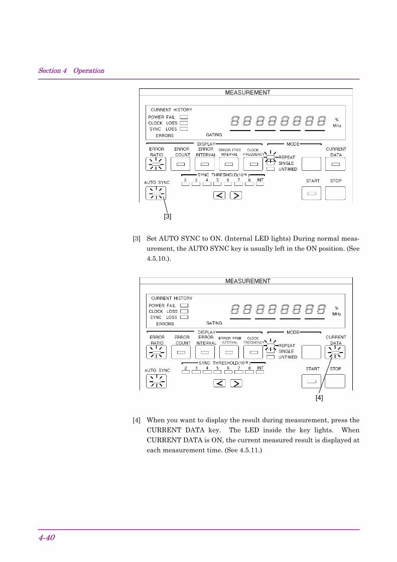
[3]
[3] Set AUTO SYNC to ON. (Internal LED lights) During normal meas-urement, the AUTO SYNC key is usually left in the ON position. (See4.5.10.).
[4]
[4] When you want to display the result during measurement, press theCURRENT DATA key. The LED inside the key lights. WhenCURRENT DATA is ON, the current measured result is displayed ateach measurement time. (See 4.5.11.)

4.5 Error Measurement
4-41
4.5.2 ERROR COUNT
[2]
[1]
[1] Press the ERROR COUNT key. The LED inside the key lights andthe ERROR COUNT measured result is displayed at DISPLAY.
[2] Set MODE (refer to Section 4.5.7) and MEAS TIME (refer to Section4.5.11) and start measurement by pressing the START key.
In the AUTO SYNC OFF state, synchronization is not established.Therefore, always leave the AUTO SYNC key in the ON position.

Section 4 Operation
4-42
4.5.3 ERROR INTERVAL[1]
[1] Press the ERROR INTERVAL key. The LED inside the key lights.
[2] Select the measurement mode. (refer to Section 4.5.7.)
[3] Set MEAS TIME. (refer to Section 4.5.11.)

4.5 Error Measurement
4-43
[4][5]
[4] When an intermediate measured result is necessary, press the CUR-RENT DATA key. The LED inside the key lights. (See 4.5.9.)
[5] Start measurement by pressing the START key.
* During measurement, always leave the AUTO SYNC key in the ONposition. (See 4.5.10.)

Section 4 Operation
4-44
4.5.4 ERROR FREE INTERVAL[1]
[1] Press the ERROR FREE INTERVAL key. The LED inside the keylights.
[2] Select the measurement mode. (See 4.5.7.)
[3] Set MEAS TIME. (See 4.5.11.)

4.5 Error Measurement
4-45
[4][5]
[4] When an intermediate measured result is necessary, press the CUR-RENT DATA key. The LED inside the key lights. (See 4.5.9.)
[5] Start measurement by pressing the START key.
* During measurement, always leave the AUTO SYNC key in the ONposition. (See 4.5.10.)

Section 4 Operation
4-46
4.5.5 CLOCK FREQUENCY[1]
[1] Press the CLOCK FREQUENCY key. The LED inside the keylights.
[2] For SYNC LOSS, CLOCK FREQUENCY is not displayed. In thiscase, make measurements with the AUTO SYNC key set to OFF.If the clock pulse is input normally, CLOCK FREQ. is correctly dis-played.

4.5 Error Measurement
4-47
4.5.6 DISPLAY display
[1]
[1] Select the item to be displayed at DISPLAY from among error ratio,error count, error intervals, error free intervals, and clock frequency.
Press the key of the item you want to display. The LED inside thekey lights.
DISPLAY display of each item is shown below.
(1) Error ratio0.0000E−16 to 1.0000E−0
(2) Error count
∆∆∆∆∆∆∆0 to ∆99999991.0000E07 to 9.9999E−16
(3) Error intervals (EI) count
∆∆∆∆∆∆∆0 to ∆9999999
(4) Error free intervals (EFI) ratio
∆∆∆0.0000 to ∆100.0000 (% units display lights)
(5) Clock frequency
∆∆∆50.000 to 12.500.000 (MHz units display lights)
Note:During sync loss, ‘–’ is displayed at all digits. If the AUTO SYNC
key is set to OFF at this time, the clock frequency is displayed.

Section 4 Operation
4-48
4.5.7 Measurement mode selection
[1]
[1] Press the MODE key and select the measurement mode. The meas-urement mode changes in REPEAT → SINGLE → UNTIMED →REPEAT... order and the LED of the selected item lights.
When selecting REPEAT or SINGLE, set the measurement time inaccordance with Section 4.5.11.
The measurement modes are defined below.
(1) REPEAT modeUnit measurement is repeated continuously during the set meas-urement time.
(2) SINGLE modeUnit measurement is performed once during the set measuring time.
(3) UNTIMED modeAfter the START key is pressed, measurement is performed continu-ously until the STOP key is pressed.

4.5 Error Measurement
4-49
4.5.8 Measurement start/stop
When the START key is pressed, the start lamp lights and measurementstarts in accordance with the measurement mode.
When the STOP key is pressed, the START lamp goes off and measure-ment stops. When the START key is pressed during measurement,
measurement is restarted.
In the SINGLE mode, when the measurement time ends before the STOPkey is pressed, the START lamp goes off automatically and measurementstops.

Section 4 Operation
4-50
4.5.9 Current data functionThe current data function can display intermediate measured results atthe specified cycle time (0.1, 0.2 secs). There are two intermediatemeasured result calculation modes: PROGRESSIVE mode and IMMEDI-ATE mode. In the PROGRESSIVE mode, the result accumulated fromthe start of measurement is displayed. In the IMMEDIATE mode, theinstantaneous result of each cycle time is displayed. An example of dis-play of the measured result for 2 seconds measurement time and 0.2 sec-
ond cycle time is shown in Fig. 4.5.9-1.
[1]
[1] Press the CURRENT DATA key. The LED inside the key lights.
[2] Set rear panel FUNCTION1 SW6. (Calculation mode setting)
SW6 0: PROGRESSIVE mode 1: IMMEDIATE mode
[3] Set rear panel FUNCTION2 SW9. (Cycle time setting)
SW9 Cycle time 0 0.1 sec 1 0.2 sec

4.5 Error Measurement
4-51
The measurement time and calculation mode have the following relation-
ship:
Displayed value
Measured value
Current data ON: PROGRESSIVE mode
Current data ON: IMMEDIATE mode
Current data OFF
All digits‘−’
All digits‘−’
All digits ‘−’
Fig. 4.5.9-1

Section 4 Operation
4-52
4.5.10 AUTO SYNC function
[1]
[1] In normal measurement, the AUTO SYNC function is turned on andinput pattern and comparison pattern synchronization is establishedautomatically. To turn on the AUTO SYNC function, press theAUTO SYNC key. The lamp inside the key lights.
The AUTO SYNC function has a normal mode, a frame mode and aquick mode. The monitor pattern during sync loss is different in thenormal mode and the frame mode. Whereas the monitor pattern inthe normal mode is all patterns, the monitor pattern in the framemode is only a specific pattern of from 4 to 32 bits (hereinafterreferred to as“frame bits”).
The frame mode can be set only when one period is a programmablepattern of at least 128 bits. The synchronization pull-in time can bemade shorter than the normal pattern by monitoring only the framebits.
[2] To set the AUTO SYNC function to the frame mode, select frame atSYNC MODE. The lamp lights and the frame sync function is turn-ed on. For a description of frame bit length and frame bit setting,see 4.4.8 Frame sync function setting.

4.5 Error Measurement
4-53
When number of errors is largeOrdinary, the AUTO SYNC function is left on during measurement.However, when the number of errors extremely large (larger than thesync pull-in value) and synchronization cannot be established, the pull-invalue can be set manually. Moreover, once synchronization has been es-tablished by AUTO SYNC function, error measurements can be made,even if the number of errors is extremely large, by tuning off the AUTOSYNC function. However, when the frequency is changed, measurement
may become impossible.
When SYNC THRESHOLD is INTSync pull-in state or sync loss state judgment is performed by syncthreshold value. In the sync pull-in state, when the error ratio exceedsthe sync loss threshold value, the sync loss state is judged. In the syncloss state, when the error ratio drops below the sync recovery thresholdvalue, the sync pull-in state is judged. When the error ratio always ex-ceeds the sync loss threshold value, pattern synchronization is not estab-lished and measurements cannot be made. However, when the error ra-tio is smaller than the sync loss threshold value, pattern synchronizationis established by setting the AUTO SYNC to ON. Thereafter, if theAUTO SYNC key is set to OFF and the pattern sync circuit is locked,measurements can be made even if the error ratio exceeds the sync lossthreshold value.
As SYNC THRESHOLD, INT or either of 10−2 to 10−8 can be selected.Refer to Fig. 4.5.10-1 for INT, and refer to Fig. 4.5.10-2 for either of 10−2 to10−8.
Example: PRBS threshold value when SYNC THRESHOLD made 10−5
(See Table 4.5.10-2.)Sync pull-in threshold value 1.56×10⁻⁵
Sync loss threshold value 5×10⁻⁵

Section 4 Operation
4-54
Table 4.5.10-1 Sync Threshold Values (At INT)
Sync threshold value Error ratio = Error countClock countMode Pattern Data length
Sync pull-in state → sync loss state(When normal)
Sync loss state → sync pull-in state(When abnormal)
PRBS 2N−1(N = 7, 9, 11, 15,20, 23, 31)
(128)×2,000 1(2,048)×2,500
=20
= 5×10⁻² (64) 1(2,048)×2
=64
= 1.56×10⁻²
2 to 16(128)×2,000 1
(2,048)×2,500=
20= 5×10⁻² (64) 1
(2,048)×2=
64= 1.56×10⁻²
17 to 160(128)×200 1
(2,048)×2,500=
200= 5×10⁻³ (64) 1
(2,048)×20=
640= 1.56×10⁻³
161 to 1,600(128)×20 1
(2,048)×2,500=
2,000= 5×10⁻⁴ (64) 1
(2,048)×200=
6,400= 1.56×10⁻⁴
1,601 to 16,000(128)×2 1
(2,048)×2,500=
20,000= 5×10⁻⁵ (64) 1
(2,048)×2,000=
64,000= 1.56×10⁻⁵
16,001 to 80,000(128)×2 1
(2,048)×12,500=
100,000= 1×10⁻⁵ (64) 1
(2,048)×5,000=
160,000= 6.25×10⁻⁶
20,001 to 160,000(128)×2 1
(2,048)×25,000=
200,000= 5×10⁻⁶ (64) 1
(2,048)×10,000=
320,000= 3.13×10⁻⁶
160,001 to 320,000(128)×2 1
(2,048)×500,000=
400,000= 2.5×10⁻⁶ (64) 1
(2,048)×20,000=
640,000= 1.56×10⁻⁶
320,001 to 524,288(128)×2 1
(2,048)×216 =524,288
= 1.9×10⁻⁶ (64) 1(2,048)×40,000
=1,280,000
= 7.81×10⁻⁷
524,289 to 1,048,576(128)×2 1
(2,048)×217 =1,048,576
= 9.54×10⁻⁷ (64) 1(2,048)×80,000
=2,560,000
= 3.91×10⁻⁷
1,648,577 to 2,097,152(128)×2 1
(2,048)×218 =2,097,152
= 4.77×10⁻⁷ (64) 1(2,048)×160,000
=5,120,000
= 1.96×10⁻⁷
2,097,153 to 4,194,304(128)×2 1
(2,048)×219 =4,194,304
= 2.38×10⁻⁷ (64) 1(2,048)×320,000
=10,240,000
= 9.80×10⁻⁸
Normal
ALTN/
DATA/
Z.S.
4,194,305 to 8,388,608(128)×2 1
(2,048)×220 =8,388,608
= 1.19×10⁻⁷ (64) 1(2,048)×640,000
=20,480,000
= 4.90×10⁻⁸
128 to 5,120(128)×100 1
(2,048)×37,500=
6,000= 1.7×10⁻⁴
5,121 to 10,240(128)×100 1
(2,048)×68,750=
11,000= 9.1×10⁻⁵
10,241 to 51,200(128)×100 1
(2,048)×10×32,500=
52,000= 1.9×10⁻⁵
51,201 to 102,400(128)×100 1
(2,048)×20×34,375=
110,000= 9.1×10⁻⁶
102,401 to 204,800(128)×100 1
(2,048)×50×26,250=
210,000= 4.8×10⁻⁶
204,801 to 307,200(128)×100 1
(2,048)×50×38,750=
310,000= 3.2×10⁻⁶
307,201 to 409,600(128)×100 1
(2,048)×50×51,250=
410,000= 2.4×10⁻⁶
409,601 to 524,288(128)×100 1
(2,048)×50×32,768=
530,000= 1.9×10⁻⁶
524,289 to 1,048,576(128)×100 1
(2,048)×687,500=
1,100,000= 9.1×10⁻⁷
1,048,577 to 2,097,152(128)×100 1
(2,048)×13,125,000=
2,100,000= 4.8×10⁻⁷
2,097,153 to 4,194,304(128)×100 1
(2,048)×26,250,000=
4,200,000= 2.4×10⁻⁷
Frame
/quick
ALTN/
DATA/
Z.S.
4,194,305 to 8,388,608(128)×100 1
(2,048)×52,500,000=
8,400,000= 1.2×10⁻⁷
256 1256×N
=N
(N: Length That is, 128 to 8,388,608)
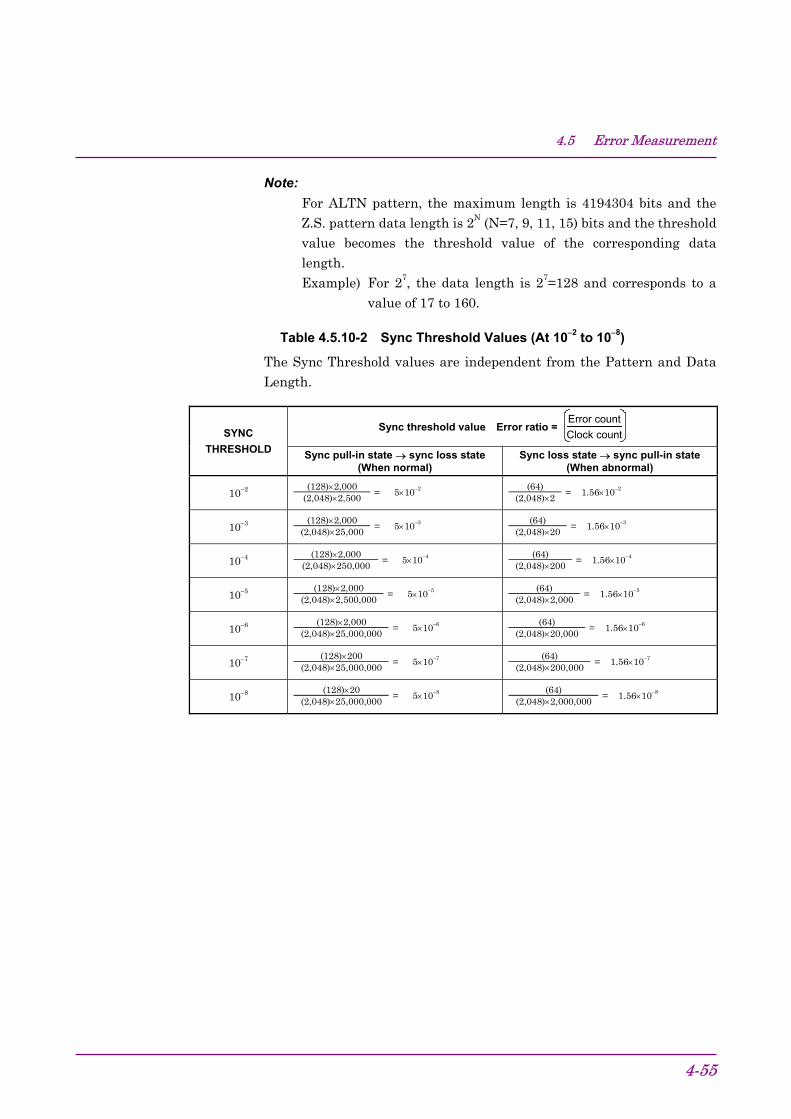
4.5 Error Measurement
4-55
Note:For ALTN pattern, the maximum length is 4194304 bits and theZ.S. pattern data length is 2N (N=7, 9, 11, 15) bits and the thresholdvalue becomes the threshold value of the corresponding datalength.Example) For 27, the data length is 27=128 and corresponds to a
value of 17 to 160.
Table 4.5.10-2 Sync Threshold Values (At 10−2 to 10−8)
The Sync Threshold values are independent from the Pattern and DataLength.
Sync threshold value Error ratio = Error countClock countSYNC
THRESHOLD Sync pull-in state → sync loss state(When normal)
Sync loss state → sync pull-in state(When abnormal)
10−2 (128)×2,000(2,048)×2,500
= 5×10⁻² (64)(2,048)×2
= 1.56×10⁻²
10−3 (128)×2,000(2,048)×25,000
= 5×10⁻³ (64)(2,048)×20
= 1.56×10⁻³
10−4 (128)×2,000(2,048)×250,000
= 5×10⁻⁴ (64)(2,048)×200
= 1.56×10⁻⁴
10−5 (128)×2,000(2,048)×2,500,000
= 5×10⁻⁵ (64)(2,048)×2,000
= 1.56×10⁻⁵
10−6 (128)×2,000(2,048)×25,000,000
= 5×10⁻⁶ (64)(2,048)×20,000
= 1.56×10⁻⁶
10−7 (128)×200(2,048)×25,000,000
= 5×10⁻⁷ (64)(2,048)×200,000
= 1.56×10⁻⁷
10−8 (128)×20(2,048)×25,000,000
= 5×10⁻⁸ (64)(2,048)×2,000,000
= 1.56×10⁻⁸
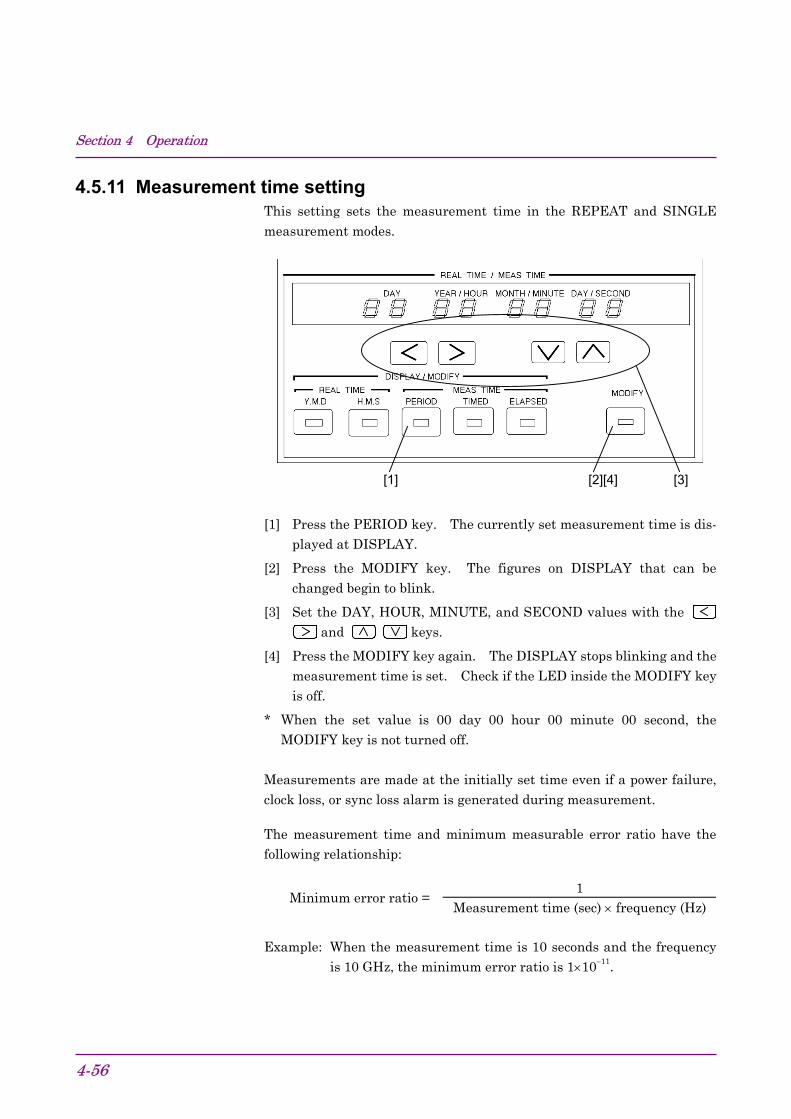
Section 4 Operation
4-56
4.5.11 Measurement time settingThis setting sets the measurement time in the REPEAT and SINGLE
measurement modes.
[3][2][4][1]
[1] Press the PERIOD key. The currently set measurement time is dis-played at DISPLAY.
[2] Press the MODIFY key. The figures on DISPLAY that can bechanged begin to blink.
[3] Set the DAY, HOUR, MINUTE, and SECOND values with the and keys.
[4] Press the MODIFY key again. The DISPLAY stops blinking and themeasurement time is set. Check if the LED inside the MODIFY keyis off.
* When the set value is 00 day 00 hour 00 minute 00 second, theMODIFY key is not turned off.
Measurements are made at the initially set time even if a power failure,
clock loss, or sync loss alarm is generated during measurement.
The measurement time and minimum measurable error ratio have thefollowing relationship:
1Minimum error ratio =
Measurement time (sec) × frequency (Hz)
Example: When the measurement time is 10 seconds and the frequencyis 10 GHz, the minimum error ratio is 1×10⁻¹¹.

4.5 Error Measurement
4-57
4.5.12 Real time settingThis setting sets the internal calendar clock.
[3][2][4][1]
[1] Press the Y.M.D or H.M.S key. The date or time is displayed atDISPLAY. Display the item to be changed.
[2] Press the MODIFY key. The figures on DISPLAY that can bechanged begin to blink.
[3] Change the date or time with the and keys.
[4] Press the MODIFY key again. The DISPLAY stops blinking andsetting is complete.
* When the set value is an impossible value, the MODIFY key is notturned off.
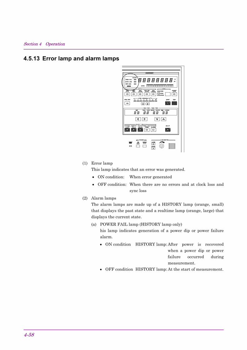
Section 4 Operation
4-58
4.5.13 Error lamp and alarm lamps
(1) Error lampThis lamp indicates that an error was generated.
• ON condition: When error generated
• OFF condition: When there are no errors and at clock loss andsync loss
(2) Alarm lampsThe alarm lamps are made up of a HISTORY lamp (orange, small)that displays the past state and a realtime lamp (orange, large) thatdisplays the current state.
(a) POWER FAIL lamp (HISTORY lamp only)his lamp indicates generation of a power dip or power failurealarm.
• ON condition HISTORY lamp: After power is recoveredwhen a power dip or powerfailure occurred duringmeasurement.
• OFF condition HISTORY lamp: At the start of measurement.

4.5 Error Measurement
4-59
(b) CLOCK LOSS lampsThese lamps indicate that a clock loss alarm was generated.
• ON condition HISTORY lamp: When clock loss alarm gen-erated during measurement.
Realtime lamp: When clock loss alarm gen-erated.
• OFF condition HISTORY lamp: At start of measurement.Realtime lamp: When clock signal recovered.
(c) SYNC LOSS lampsThese lamps indicate that a sync loss alarm was generated.
• ON condition HISTORY lamp: When sync loss alarm gener-ated during measurement.
Realtime lamp: When sync loss alarm gener-ated.
• OFF condition HISTORY lamp: At start of measurement.Realtime lamp: When synchronization re-
covered and when clock lossalarm generated and whenthe AUTO SYNC key is OFF.

Section 4 Operation
4-60
4.5.14 Error detection mode settingErrors are detected by comparing each bit of the input pattern to an in-ternally generated pattern. The error detection mode has three kinds oferrors: total error, insertion error, and omission error. The kind of error
is selected by rear panel FUNCTION1 SW7 and SW8 as shown below.
SW7 SW8 Error0 0 Total error0 1 Insertion error1 0 Omission error1 1 Total error
In the insertion error mode, the pattern is detected only as an error of BITthat changed from “0” to “1”. In the omission error mode, the pattern isdetected as an error of only BIT that changed from “1” to “0”. In the totalerror mode, all errors are detected.
In Fig. 4.5.14-1, the pattern logic was set to positive logic. When the pat-tern logic was set to negative logic, (d) becomes an omission error and (e)
becomes an insertion error.
(a) Input pattern
(b) Internal pattern
(c) Total error
(d) Insertion error
(e) Omission error
Fig. 4.5.14-1 Error Detection Mode

4.6 Memory (Floppy Disk)
4-61
4.6 Memory (Floppy Disk)
[1] [2] [3] [4]
No. Name[1] File No. selection[2] File control[3] Mode selection[4] Eject
4.6.1 File save
[1]
[4] [3] [2]
[1] Insert a formatted disk (2HD, 2DD) into the floppy disk drive. (For adescription of the formatting method, refer to Section 4.6.3 “Diskformatting.”)
[2] Select the PATT mode or OTHERS mode.
PATT mode: Stores the contents set at Section 4.4.
OTHERS mode: Stores the contents other than PATT.
[3] Press the DIR/File No. key. The File No. LED lights.
[4] Set the file name (00 to 99) with the keys.
[5] Press the SAVE key and save the file.

Section 4 Operation
4-62
* If another file was previously saved under the same file name, thecurrent file cannot be saved with the SAVE key. If the old file isunnecessary, a new file can be saved by pressing the SHIFT key, thenpressing the SAVE key. If the old file is necessary, save the new fileby changing its file name.
Note:When there is not enough vacant space on the FD to resave files,files cannot be resaved. In this case, to try to resave files, “DE-
LETE” files from the FD.
Files larger than 720 k cannot be resaved to an FD formatted at1.44 M.
4.6.2 File recall
[2] [1] [3]
[1] Insert the disk into the floppy disk drive and select the DIR mode.When the FD was changed, always execute the DIR command.
[2] Press the keys and check if the file exists. If the file exists,only its file name is displayed. However, if the file is not on the in-serted floppy, “– –” is displayed.
[3] Press the RECALL key and call the contents of the file.

4.6 Memory (Floppy Disk)
4-63
4.6.3 Disk formatting
[3] [6] [5] [2][1][4]
[1] Insert an unformatted floppy disk into the floppy disk drive.
[2] Select the PATT mode or OTHERS mode.
[3] Select the FILE No. mode.
[4] Hold down the key. “Fr” is displayed. (Fr is displayed after 99.)
[5] Select the SHIFT mode.
[6] When the DELETE key is pressed, formatting starts.
Note:The formatting format can be switched between 1440 KB/720 KB or1232 KB/640 KB by rear panel FUNCTION switch. However, ifthe format was changed, turn the power off, then turn it back on.
4.6.4 File delete
[4] [3] [2][1][5]
[1] Insert the floppy disk into the floppy disk drive and select the nameof the file you want to delete.
[2] Press the SHIFT key.
[3] Press the DELETE key. The file with the displayed file name is deleted.
[4] (Confirmation) Execute the DIR command.
[5] Press the keys and check that the deleted file name is notdisplayed.

Section 4 Operation
4-64
4.6.5 Error messagesWhen a floppy disk error was generated, an error code of from E0 to E9 isdisplayed on the file name display. For the error display, see Table4.6.5-1 Error Messages. The error messages are cleared each time the
keys are pressed.
Table 4.6.5-1 Error Messages
Error item Error contentsE0 Media error (Formatting, media error)E1 Write protection error (Protection error when writing)E2 File full (Write area too small)E3 File not found (Specified file could not be found when
reading.)E4 File exists error (An attempt was made to save the same file)E5 Write error (Write obstruction error)E6 Read error (Read obstruction error)E7 File type, File error (File type or file contents error)E8 FD error (Other error)E9 Hardware error (Hardware trouble error)
4.6.6 Floppy disk(a) Disk type
Floppy disks are formatted in the standard MS-DOS format providedby the MS-DOS handler. The type of formatted floppy disk is datadisk. This is because the MS-DOS file handler does not copy theMS-DOS system. A system disk containing the MS-DOS system canalso be used to store data.
(b) Volume labelA volume label is added when the floppy disk is formatted.
Volume label: MP1764AThis volume label is provided to identify the floppy disk.
(c) File structure
• Directory structureRoute directory only.
• File name, extensionThe file name and extension have the following format:
File name RR××00 to 99 (file name)
Extension PTN: Pattern fileOTH: Parameter file other than pattern
Examples: RR99. PTNRR01. OTH

4.6 Memory (Floppy Disk)
4-65
(d) Data formatThe format of the data stored on floppy disk is, as a rule, not madepublic. Therefore, when data creation, updating, etc. are performedusing a personal computer that runs under MS-DOS, operation is notguaranteed. However, there is no problem in checking the file di-rectory or copying files.
(e) CompatibilityThe MP1764D Error Detector ‘PTN’ file mode can be used with theMP1763B/C Pulse Pattern Generator. The ‘OTH’ file cannot beused with the MP1763B/C Pulse Pattern Generator.The MP1764D cannot read the files of the old MP1702A, MP1609A,
and MP1653A Error Detectors.
4.6.7 Floppy disk precautions• Do not remove a floppy disk from the floppy disk drive while it is being
accessed.
• Observe the specified environmental conditions, and do not use thefloppy disk in dusty places.
• Clean head of floppy disk drive with 3.5 inch head cleaning disk setregularly.
• Do not place a magnetized object near the floppy disk and do not bendthe floppy disk.
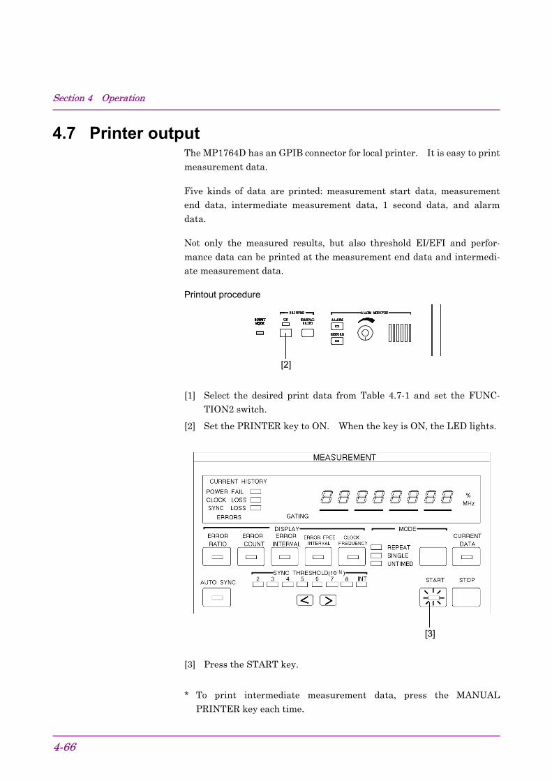
Section 4 Operation
4-66
4.7 Printer outputThe MP1764D has an GPIB connector for local printer. It is easy to print
measurement data.
Five kinds of data are printed: measurement start data, measurementend data, intermediate measurement data, 1 second data, and alarmdata.
Not only the measured results, but also threshold EI/EFI and perfor-mance data can be printed at the measurement end data and intermedi-ate measurement data.
Printout procedure
[2]
[1] Select the desired print data from Table 4.7-1 and set the FUNC-TION2 switch.
[2] Set the PRINTER key to ON. When the key is ON, the LED lights.
[3]
[3] Press the START key.
* To print intermediate measurement data, press the MANUALPRINTER key each time.

4.7 Printer output
4-67
The print data contents are shown below.
Table 4.7-1 Print Data Contents
Print data contents Print timing Printing restrictionMeasure-mentstart data
• Measurement start time • At the start ofmeasurement.
None
Measure-ment enddata
• Measurement start time• Measurement end time• Measurement elapsed
time• Measured result
Measurement Error ratiovalue Error count
EI countEFI ratio
Alarm Power failureintervals Clock loss
Sync loss
• Threshold EI and EFIdata
• Error performance data
• At the end ofmeasurement
• The following can be selectedwith FUNCTION2 SW1, SW2,and SW3.SW10: Print all measured result1: Print only error ratio and
error count of measuredresult
SW20: Do not print threshold EI
and EFI data.1: Print threshold EI and EFI
data.SW30: Do not print error
performance data.1: Print error performance data.
Intermed-iatemeasure-mentdata
• Same as measurementend data.However, the measure-ment end time is replacedby the intermediatemeasurement time.
• When MANUALPRINT key pressed.
• When intermediatedata printing isselected:
1. When measurementtime is less than 2days, every 2 hours.
2. When measurementtime is 2 days ormore, every day.
3. In UNTIMED mode,every day.
• The following can be selectedwith FUNCTION2 SW4.0: Do not print intermediate
data.1: Print intermediate data.
• Except for the above, the sameas measurement end data.

Section 4 Operation
4-68
Table 4.7-1 Print Data Contents (Continued)
Print data contents Print timing Printing restriction
• The following can be selectedwith FUNCTION2 SW5, SW6,SW7, and SW8:
SW50: Do not print 1 second data.1: Print 1 second data.
SW6 and SW7SW6 SW7 Function
0 0 When error >0,print 1 seconddata.
0 1 When error>10−6, print 1second data.
1 0 When error>10−4, print 1second data.
1 1 When error>10−3, print 1second data.
1 seconddata
• Generation time• 1 second average error
ratio• 1 second error count
• Every second
SW80: Paper save function off1: Paper save function on
Alarmdata
• Power failure generationtime
• Power failure recoverytime
• Clock loss generation time• Clock loss recovery time• Sync loss generation time• Sync loss recovery time• Unavailable seconds
• Time alarmgenerated and whenalarm recovered.However, the powerfailure generationtime is when thepower is recovered.
None
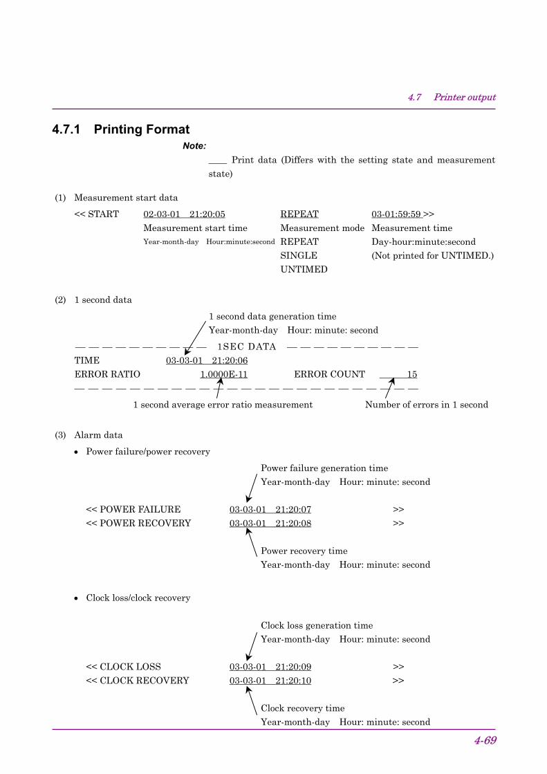
4.7 Printer output
4-69
4.7.1 Printing FormatNote:
Print data (Differs with the setting state and measurement
state)
(1) Measurement start data
<< START 02-03-01 21:20:05 REPEAT 03-01:59:59 >>Measurement start time Measurement mode Measurement timeYear-month-day Hour:minute:second REPEAT Day-hour:minute:second
SINGLE (Not printed for UNTIMED.)UNTIMED
(2) 1 second data
1 second data generation timeYear-month-day Hour: minute: second
1SEC DATA TIME 03-03-01 21:20:06ERROR RATIO 1.0000E-11 ERROR COUNT 15
1 second average error ratio measurement Number of errors in 1 second
(3) Alarm data
• Power failure/power recovery
Power failure generation timeYear-month-day Hour: minute: second
<< POWER FAILURE 03-03-01 21:20:07 >><< POWER RECOVERY 03-03-01 21:20:08 >>
Power recovery timeYear-month-day Hour: minute: second
• Clock loss/clock recovery
Clock loss generation timeYear-month-day Hour: minute: second
<< CLOCK LOSS 03-03-01 21:20:09 >><< CLOCK RECOVERY 03-03-01 21:20:10 >>
Clock recovery timeYear-month-day Hour: minute: second

Section 4 Operation
4-70
• Sync loss/sync recovery
Sync loss generation timeYear-month-day Hour: minute: second
<< PATTERN SYNC LOSS 03-03-01 21:20:11 >><< PATTERN SYNC RECOVERY 03-03-01 21:20:12 >>
Sync recovery timeYear-month-day Hour: minute: second
(4) Measurement end data and intermediate measurement dataThere are two output formats, standard format and abbreviated format. These formats are de-scribed below in the order: (a) Standard format and (b) abbreviated format.
(a) Standard format
Line 1 ****************************************************************************
Line 2 START 03-03-01 21:20:13 END 03-03-01 21:20:14
Measurement start time Measurement end data Measurement end time
Year-month-day INT for intermediate or intermediate
Hour: minute: second measurement data measurement time
Line 3 ERROR MEASUREMENT
Line 4 ERROR RATIO 1.0000E-11 ERROR COUNT 25
Average error ratio Number of errors
Line 5 ERROR INTVL 1 %ERROR FREE INTVL 0
Number of error intervals Error free intervals ratio
Line 6 POWER FAIL INTVL 0 CLOCK LOSS INTVL 0
Number of power fail intervals Number of clock loss intervals
Line 7 SYNC LOSS INTVL 0
Number of sync loss intervals
Line 8
Line 9 ****************************************************************************
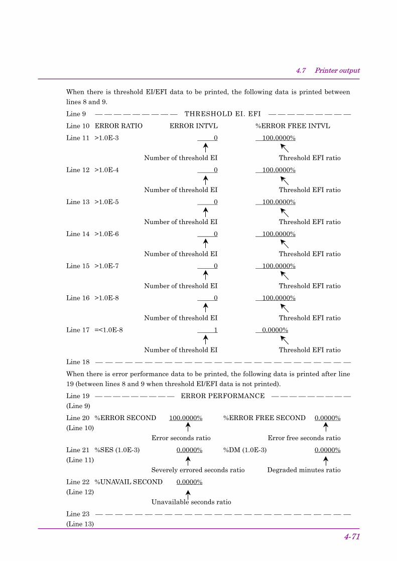
4.7 Printer output
4-71
When there is threshold EI/EFI data to be printed, the following data is printed betweenlines 8 and 9.
Line 9 THRESHOLD EI. EFI
Line 10 ERROR RATIO ERROR INTVL %ERROR FREE INTVL
Line 11 >1.0E-3 0 100.0000%
Number of threshold EI Threshold EFI ratio
Line 12 >1.0E-4 0 100.0000%
Number of threshold EI Threshold EFI ratio
Line 13 >1.0E-5 0 100.0000%
Number of threshold EI Threshold EFI ratio
Line 14 >1.0E-6 0 100.0000%
Number of threshold EI Threshold EFI ratio
Line 15 >1.0E-7 0 100.0000%
Number of threshold EI Threshold EFI ratio
Line 16 >1.0E-8 0 100.0000%
Number of threshold EI Threshold EFI ratio
Line 17 =<1.0E-8 1 0.0000%
Number of threshold EI Threshold EFI ratio
Line 18
When there is error performance data to be printed, the following data is printed after line19 (between lines 8 and 9 when threshold EI/EFI data is not printed).
Line 19 ERROR PERFORMANCE (Line 9)
Line 20 %ERROR SECOND 100.0000% %ERROR FREE SECOND 0.0000%(Line 10)
Error seconds ratio Error free seconds ratio
Line 21 %SES (1.0E-3) 0.0000% %DM (1.0E-3) 0.0000%(Line 11)
Severely errored seconds ratio Degraded minutes ratio
Line 22 %UNAVAIL SECOND 0.0000%(Line 12)
Unavailable seconds ratio
Line 23 (Line 13)
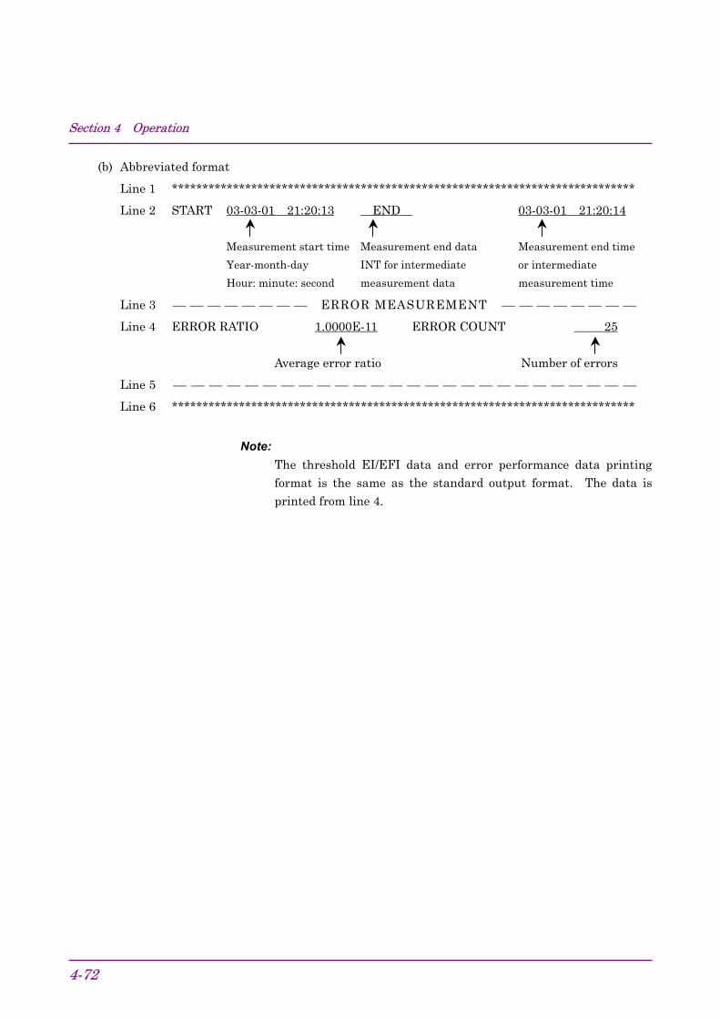
Section 4 Operation
4-72
(b) Abbreviated format
Line 1 ****************************************************************************
Line 2 START 03-03-01 21:20:13 END 03-03-01 21:20:14
Measurement start time Measurement end data Measurement end time
Year-month-day INT for intermediate or intermediate
Hour: minute: second measurement data measurement time
Line 3 ERROR MEASUREMENT
Line 4 ERROR RATIO 1.0000E-11 ERROR COUNT 25
Average error ratio Number of errors
Line 5
Line 6 ****************************************************************************
Note:The threshold EI/EFI data and error performance data printingformat is the same as the standard output format. The data is
printed from line 4.
4.8 Definition of Terms
4-73
4.8 Definition of Terms4.8.1 Measurement items
(1) Error ratio
Number of error pulses in measurement timeNumber of clock pulses in measurement time
(2) Error count
Number of error pulses in measurement time.
(3) Error intervals (EI) countNumber of intervals (1 second) containing one or more error pulses inmeasurement time.
(4) Error free intervals (EFI) ratioRatio of total number of intervals with number of intervals (1 second)containing one or more error pulses to total number of intervals inmeasurement time. It is calculated from EI with the followingequation:
number of measurement intervals − EIEFI =
Number of measurement intervals× 100%
(5) Clock frequencyOne second clock frequency.
4.8.2 Alarm intervals(1) Power failure alarm intervals
Number of intervals (1 second) at which a power failure occurred.
(2) Clock loss intervalsNumber of intervals (1 second) at which a clock loss alarm was gen-erated.
(3) Sync loss intervalsNumber of intervals (1 second) at which a sync loss alarm was gener-ated.

Section 4 Operation
4-74
4.8.3 Threshold EI and EFI data(1) Threshold EI
Number of intervals (1 second) that the 1 second average error ratiosatisfies each of the following thresholds in the measurement time.
1 second average error ratio > 10−3, >10−4, >10−5, >10−6, >10−7, >10−8, ≤10−8
(2) Threshold EFIRatio of the number of intervals at which the 1 second average errorratio does not satisfy each threshold condition of item (1) to the totalnumber of intervals.
The threshold EFI is calculated from EI with the following equation:
Number of measurement intervals − threshold EIThreshold EFI =
Number of measurement intervals× 100%
4.8.4 Error performance dataThe interval from the start of measurement to the end of measurementsis divided into available periods and unavailable periods, with 1 secondinterval as the unit. Each item is calculated for the available periods.
(1) Definition of unavailable period and available periodWhen an interval at which the 1 second average error ratio exceedsthe unavailable threshold (unavailable period) continues for 10 sec-onds, the unavailable period starts and this 10 seconds is included inthe unavailable seconds.
When an interval at which the 1 second average error ratio does notexceed the unavailable threshold (available interval) continues for 10seconds in an unavailable period, the unavailable period ends andthis 10 seconds is included in the available seconds.
Each is subdivided into two states, with the periods that are not un-available periods as available periods.
• Unavailable period (after confirmation)This is the state after the last interval was calculated in the un-available seconds. When an interval is an unavailable interval,it is calculated in the unavailable seconds and the state does notchange.
When an interval is an available interval, the unavailable sec-onds and available seconds do not change and the state changesto unavailable seconds (during judgment).

4.8 Definition of Terms
4-75
• Unavailable period (during judgment)This is the state during which whether the last interval was in-cluded in unavailable seconds or available seconds during an un-available interval is judged.
When the interval is an unavailable interval, the continuationseconds of this state is calculated in the unavailable seconds andthe state changes to unavailable period (after confirmation).
When the interval is an available interval, and the number ofconsecutive available intervals reached 10, the continuation timeof this state (=10 seconds) is calculated in the available secondsand the state changes to available period (after confirmation).When the number of consecutive available intervals is less than10, the unavailable seconds and available seconds do not changeand this state continues.
• Available period (after confirmation)This is the state after the last interval was calculated in theavailable seconds.
When the interval is an available interval, it is calculated in theavailable seconds and the state does not change.
When the interval is an unavailable interval, the available sec-onds and unavailable seconds do not change and the statechanges to available seconds (during judgment).
• Available seconds (during judgment)This is the state during which whether the last interval is includ-ed in the available seconds in an available period.
When the interval is an available interval, the continuation timeof that state is calculated in the available seconds and the statechanges to available period (after confirmation).
When the interval is an unavailable interval, and the number ofconsecutive unavailable intervals reached 10, the continuationtime (=10 seconds) of this state is calculated in the unavailableseconds and the state changes to unavailable period (after con-firmation). When the number of consecutive unavailable inter-vals is less than 10, the available seconds and unavailable sec-onds do not change and this state is continued.
The initial state is available period (after confirmation).

Section 4 Operation
4-76
(2) Unavailable threshold, DM thresholdThe following can be selected with FUNCTION1 SW4:
0: Unavailable threshold = 10−3, DM threshold = 10−6
1: Unavailable threshold = 10−4, DM threshold = 10−8
(3) Measurement items
• Unavailable SecondsRatio of unavailable seconds to measurement time.
• Errored SecondsRatio of error intervals calculated in available seconds to all in-tervals calculated in available seconds.
• Error Free SecondsRatio of error free intervals calculated in available seconds to allintervals calculated in available seconds.
• Severely Errored Seconds (SES)Ratio of unavailable intervals calculated in available seconds toall intervals calculated in available seconds.
• Degraded MinutesThe error ratio is calculated for every 60 packets, excluding theSES above at the available interval calculated in the availableseconds. The error ratio is the ratio of the number of packets ex-ceeding the DM threshold to the total number of packets.

4.9 Processing of Measurement Data at Alarm Generation
4-77
4.9 Processing of Measurement Data at AlarmGeneration
(1) Power failureWhen a power failure alarm is generated during measurement, themeasurement data up to the interval before the interval that gener-ated the power failure alarm is saved during the power failure.
If the measurement data was correctly saved, measurement is con-tinued after the power recovers.
(a) Error measurementThe number of error pulses and the number of clock pulsescounted in the interval that generated the power failure alarmare removed from calculation.
(b) Interval measurement, threshold interval measurementThe interval that generated the power failure alarm and the in-terval during continuation of the power failure are included onlyin the power failure intervals calculation and are included inother calculations.
(c) Error performanceThe interval being judged when a power failure alarm was gen-erated is not included in neither unavailable seconds nor avail-able seconds calculation.
After the power recovers, measurement restarts from the initialstate.
(2) Clock lossWhen a clock loss alarm is generated during measurement, one of thefollowing two processings can be selected:
(a) Removal of clock loss processing from calculation (FUNCTION1SW2 set to 0.)
(i) Error measurementThe number of error pulses and number of clock pulsescounted in the interval that generated the clock loss alarmare removed from calculation.
(ii) Interval measurement, threshold interval measurementIntervals whose interval status is clock loss are included inclock loss intervals calculation only. They are not includedin other calculations.

Section 4 Operation
4-78
(iii) Error performanceIntervals whose interval status is clock loss are not includedin neither unavailable seconds or available seconds calcula-tion. The interval being judged is not included in unavail-able seconds or available seconds calculation either.
When the interval status is no longer clock off, measure-ment is continued from the initial state.
(b) Inclusion of clock loss processing in calculation (FUNCTION1SW2 set to 1.)
(i) Error measurementThe number of error pulses and number of clock pulsescounted in the interval that generated the clock loss alarmare removed from calculation.
(ii) Interval measurement, threshold interval measurementIntervals whose interval status is clock loss are included inclock loss intervals and total intervals calculation, but arenot included in threshold EI calculation.
(iii) Error performanceIntervals whose interval status is clock loss become un-available intervals and when they were included in avail-able seconds calculation, they are also included in error sec-onds calculation.
(3) Sync lossWhen a sync loss alarm is generated during measurement, one of thefollowing two processings can be selected:
(a) Removal of sync loss processing from calculation (FUNCTION1SW3 set to 0)
(i) Error measurementThe number of error pulses and number of clock pulsescounted in the interval that generated the sync loss alarmare removed from calculation.
(ii) Interval measurement, threshold interval measurementIntervals whose interval status is sync loss are includedonly in sync loss intervals calculation. They are not in-cluded in other calculations.
(iii) Error performanceIntervals whose interval status is sync loss are not includedin neither unavailable seconds nor available seconds calcu-lation. The interval being judged is not included in un-available seconds and available seconds calculations either.
When the interval status is not longer sync loss, measure-ment is continued from the initial state.

4.9 Processing of Measurement Data at Alarm Generation
4-79
(b) Inclusion of sync loss processing in calculations (FUNCTION1SW3 set to 1.)
(i) Error measurementThe number of error pulses and the number of clock pulsescounted in the interval that generated the sync loss alarmare removed from all calculations.
(ii) Interval measurement, threshold interval measurementIntervals whose interval status is sync loss are included insync loss intervals and total intervals calculations, but arenot included in threshold EI calculation.
(iii) Error performanceIntervals whose interval status is sync loss become unavail-able intervals and when they were included in availableseconds calculation, they are also included in error secondscalculation.

Section 4 Operation
4-80
4.10 FUNCTION Switch SettingThe setting contents of the FUNCTION1 and 2 switches on the rear panel
of the mainframe show below.
When the FUNCTION2 SW10 setting was changed, turn on the main-frame power again.
* When the setting of the other FUNCTION switches was changed, thepower does not have to be turned on again.
Notes:1. When the system control setting was changed, turn on the
power again.
2. The FUNCTION switch on the rear panel is covered with thepanel and fasten with screws to decrease the radio activeradiation. To change the FUNCTION switch, remove the panel
for the setting.
FUNCTION 1
Marking Function1 BIT SHIFT NUMBER FOR
MARK RATIO VARIEDNumber of AND shift bits at mark ratio setting switch0: 1 bit1: 3 bits
2 CLOCK LOSSEVALUATION
Clock loss processing function selector switch0: Do not measure and evaluate clock loss1: Measure and evaluate clock loss
3 SYNC LOSSEVALUATION
Sync loss processing function selector switch0: Do not measure and evaluate sync loss1: Measure and evaluate sync loss
4 ERRORPERFORMANCETHRESHOLD
Error performance threshold selector switch0: 10−3
1: 10−4
5 BURST MODE Burst mode switch0: OFF1: ON
6 CURRENT DATACALCULATION
Calculation mode of intermediate measurement datadisplayed when CURRENT DATA key ON selector switch0: Progressive mode1: Immediate modeError detection mode selector switch
SW7 SW8 Error mode0 0 Total error0 1 Insertion error1 0 Omission error1 1 Total error
7, 8 ERROR
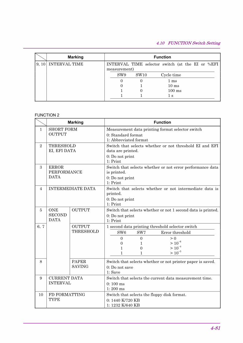
4.10 FUNCTION Switch Setting
4-81
Marking FunctionINTERVAL TIME selector switch (at the EI or %EFImeasurement)
SW9 SW10 Cycle time0 0 1 ms0 1 10 ms1 0 100 ms1 1 1 s
9, 10 INTERVAL TIME
FUNCTION 2
Marking Function1 SHORT FORM
OUTPUTMeasurement data printing format selector switch0: Standard format1: Abbreviated format
2 THRESHOLDEI, EFI DATA
Switch that selects whether or not threshold EI and EFIdata are printed.0: Do not print1: Print
3 ERRORPERFORMANCEDATA
Switch that selects whether or not error performance datais printed.0: Do not print1: Print
4 INTERMEDIATE DATA Switch that selects whether or not intermediate data isprinted.0: Do not print1: Print
5 OUTPUT Switch that selects whether or not 1 second data is printed.0: Do not print1: Print1 second data printing threshold selector switch
SW6 SW7 Error threshold0 0 > 00 1 > 10−6
1 0 > 10−4
1 1 > 10−3
6,7 OUTPUTTHRESHOLD
8
ONESECONDDATA
PAPERSAVING
Switch that selects whether or not printer paper is saved.0: Do not save1: Save
9 CURRENT DATAINTERVAL
Switch that selects the current data measurement time.0: 100 ms1: 200 ms
10 FD FORMATTINGTYPE
Switch that selects the floppy disk format.0: 1440 K/720 KB1: 1232 K/640 KB

Section 4 Operation
4-82.

Section 5 Principle of Operation
5-1
5.1 Pseudorandom Pattern (PRBS Pattern).................... 5-25.2 Pattern Synchronized Output Synchronization.......... 5-4
5.2.1 Pseudorandom pattern.................................. 5-45.2.2 Programmable pattern................................... 5-4
5.3 Error Output ............................................................... 5-6

Section 5 Principle of Operation
5-2
5.1 Pseudorandom Pattern (PRBS Pattern)The principle of pseudorandom pattern generation is shown in Table 5.1-1. The pseudorandom pattern is represented by the N-order generationpolynomial shown in Table 5.1-1. One period is 2N−1. A PRBS pattern
with a 2N−1 period produces an N bits continuous “1” pattern per period.
When LOGIC is set to POS (positive logic), PRBS pattern output level “1”corresponds to low level and “0” corresponds to high level.
The PRBS pattern mark ratio is generated by the block shown in Fig.5.1-1. There are four mark ratios of 1/2, 1/4, 1/8, and 0/8 (all 0). For 1/4and 1/8, 2 bit shift or 3 bit shift can be selected by rear panel DIP switch.Refer to Section 4.10 “FUNCTION Switch Setting.”
When the rear panel 1/8 SPEED output is PRBS pattern, a pattern like
that shown in Fig. 5.1-2 is produced.
Table 5.1-1 Principle of Pseudorandom Pattern Generation
Period Generationpolynomial Pattern generation block diagram
27−1 1+X6+X7
Output
29−1 1+X5+X9
Output
211−1 1+X9+X11
Output
215−1 1+X14+X15
Output
220−1 1+X3+X20
Output
223−1 1+X18+X23
Output
231−1 1+X28+X31
Output
N : Shift register: Exclusive-OR

5.1 Pseudorandom Pattern (PRBS Pattern)
5-3
PRBS patterngenerator
Shift register
(See Table 5.1-1)
Mark ratio
1 2 3 4 5 6 1/2
1/4 (1 bit shift)
1/8 (1 bit shift)
1/4 (3 bit shift)
1/8 (3 bit shift)
Fig. 5.1-1 Mark Ratio 1/4, 1/8 Pattern Generation Circuit
DATA1
DATA2
DATA3
DATA4
DATA5
DATA6
DATA7
DATA8
2N−1 BIT
2N/8 bitsleading
2N/8 bitsleading
2N/8 bitsleading
2N/8 bitsleading
2N/8 bitsleading
2N/8 bitsleading
2N/8 bitsleading
(2N/8)−1 bit
For example, when PRBS 215−1, 215/8=4096 bits.
Fig. 5.1-2 Example of Pseudorandom Pattern

Section 5 Principle of Operation
5-4
5.2 Pattern Synchronized Output Synchronization5.2.1 Pseudorandom pattern
1Period =
(Set frequency)×(2N−1)×128
N = 7, 9, 11, 15, 20, 23, 311
(Where pulse width =(Set frequency)
×64 plus pulses)
5.2.2 Programmable pattern(1) Data pattern, alternate pattern
(a) Data length = 65536 or less
1Period =
(Set frequency)×(128 and lowest commondenominator of data length)
(Example 1) Data = 81
Period =(Set frequency)
×128
(Example 2) Data = 101
Period =(Set frequency)
×640
(b) Data length > 65536
1Period =
(Set frequency)×(data length)
(2) Zero Sub pattern
1Period =
(Set frequency)×2N N = 7, 9, 11, 15
(3) Pulse width
For any of the programmable patterns above, the pulse width is
pulse width =1
(Set frequency)×64.
The output signal polarity is plus pulse.
5.2 Pattern Synchronized Output Synchronization
5-5
Note:For alternate pattern, the sync pulse is output in basic data lengthunits. When the data output is observed with a sampling oscillo-
scope, pattern A and pattern B appear to be superimposed.
When you want to observe the data output pattern A or pattern Bwithout being superimposed, input the rear panel A/B TIMINGOUTPUT of MP1763C to a sampling oscilloscope trigger via anECL terminator.

Section 5 Principle of Operation
5-6.
5.3 Error OutputThe error output can be of two types, direct error and stretched error.The error detection block diagram is shown in Fig. 5.3-1 and the error
output pulse is illustrated in Fig. 5.3-2.
Input data 1/128 DEMUXcircuit
Standard patterngenerator
Errordetection
circuit
1/128data
1/128data
1/128 clock
(RZ)1/128OR error
1/128 error1
127
128
Pulse widthstretcher circuit
Directerror
Stretchederror
2
Fig. 5.3-1 Error Output Block Diagram
0 V−1 V
HL
1/128 OR error
1/128 clock
Direct error(0/−1 V)
Stretched error(TTL)
Approx. 350 ns
T64T = f
Example:When f=10 GHzT = 6.4 ns
Note:
Indicates an ERROR.
Fig. 5.3-2 Error Output Pulse

Section 6 Measurement
6-1
This section describes an example of DFF IC evaluation using the
MP1764D Error Detector and MP1763B/C Pulse Pattern Generator.
6.1 Set-up ........................................................................ 6-26.2 Measurement ............................................................. 6-36.3 Burst Measurement ................................................... 6-4

Section 6 Measurement
6-2
6.1 Set-upMP1764D
MP1763B/C
OUT IN
QQ DD
C
[1] Ground the system by connecting GND of the measuring instrumentsand the device under test.
[2] Connect the power cord.
[3] Connect the input/output signals using the accessory semirigid cableor an equivalent coaxial cable. At this time, short the center con-ductor of the cable with tweezers, etc. before use.

6.2 Measurement
6-3
6.2 Measurement[1] Initialize the MP1763B/C and MP1764D. Set the POWER switch to
ON while pressing the LOCAL key.
[2] Set the DATA and CLOCK1 outputs on the MP1763B/C to a levelconforming to the DFF IC input conditions.
[3] Set the termination condition of the MP1764D according to the DFFIC output conditions (SINGLE-ENDED/50 Ω (GND/–2 V), DIFFER-ENTIAL/100 Ω).
[4] Turn on the power of the device under test.
[5] Set the MP1763B/C frequency to the measurement frequency, andthe OUTPUT to ON.
[6] Press the MP1764D AUTO SYNC key and START key, then pressthe AUTO SEARCH key. After the end of AUTO SEARCH, checkthat all the error and alarm lamps are off. If an error lamp is lit,change the MP1763B/C CLOCK phase.
[7] While watching the MP1764D ERRORS lamp, change theMP1763B/C offset voltage and amplitude and measure the inputlevel margin of the IC under test.

Section 6 Measurement
6-4.
6.3 Burst MeasurementTo perform the burst measurement, set the function sw5 (BURST MODE)on the MP1764D rear panel to ON and connect the MP1764D to theMP1763B/C and DUT as shown below:
MP1764D
MP1763B/C
DUTRESYNCINPUT
Burst timing
C
D D D D
* Ground the grounding terminal before wiring the MP1763B/C,MP1764D, and DUT.
DATA OUTPUT(MP1763B/C)
BURST DATA(DUT)
BURST TIMING(DUT)
ERRORMEASUREMENTRANGE
Pull in
Completion of pull in(Measurement restart)
Burst measurementRestart the burst measurement after termination of the burst timing andcompletion of pull in. In other words, the measurement inhibiting timeis the time of burst timing added by the pull-in time.Set the pull-in time to be approx. 2 µs or less (value for reference whenthe PRBS pattern is input to the MP1764D as burst data from @9.953Gbit/s, MP1763B/C) as a rough standard.When the clock recovery function is used, a pull-in time of approx. 8 µs orless is further needed. Moreover, the pull-in time differs depending onthe operation bit-rate.

Section 7 Performance Check
7-1
7.1 When Performance Check Necessary ...................... 7-27.2 Test Equipment.......................................................... 7-37.3 Check Method............................................................ 7-4
7.3.1 Operating frequency...................................... 7-47.3.2 Input data level .............................................. 7-67.3.3 Input clock level ............................................. 7-77.3.4 Pattern ........................................................... 7-87.3.5 Measurement items....................................... 7-9

Section 7 Performance Check
7-2
7.1 When Performance Check NecessaryPerformance checks are performed to check that the main performancesof the MP1764D satisfy the ratings. Carry out the performance checksduring receiving inspection, operation confirmation after repair, and peri-
odic inspection (every six months).

7.2 Test Equipment
7-3
7.2 Test EquipmentThe test equipment needed for performance check are shown in Table
7.2-1.
Table 7.2-1 Performance Check Test Equipment
Test equipmentname (Anritsu) Required performance Measurement
itemPulse patterngenerator(MP1763B/C)
Operating frequency:50 MHz to 12.5 GHz
Other performances:Equivalent to MP1763B/C
• Operatingfrequency
• Input level• Pattern• Measurement
itemsSampling oscilloscope Bandwidth: 50 GHz minimum

Section 7 Performance Check
7-4
7.3 Check MethodBefore starting performance checks, allow the MP1764D and the other
test equipment to warm up for at least 30 minutes.
7.3.1 Operating frequency(1) Rating
50 MHz to 12.5 GHz
CLOCK RECOVERY Operation Bit-rate
62.5 to 100 Mbit/s,125 to 200 Mbit/s,250 to 400 Mbit/s,500 to 800 Mbit/s,1.000 to 1.600 Gbit/s,2.000 to 3.200 Gbit/s,4.250 Gbit/s,9.900 to 11.100 Gbit/s
(2) Setup
MP1764D
MP1763B/CGround wire
Semiriged cable supplied
Fig. 7.3.1-1 MP1763B/C and MP1764D Setup

7.3 Check Method
7-5
(3) Procedures
[1] Set up the equipment as shown in Fig. 7.3.1-1.
[2] While pressing the MP1763B/C and MP1764D LOCAL key, setthe POWER switch to ON and place the instruments into theinitialize state. Then, set the MP1763B/C OUTPUT to ON, andpress the MP1764D AUTO SYNC and START key.
[3] Set the MP1763B/C FREQUENCY to an arbitrary value withthe frequency setting knob.
[4] Press the MP1764D AUTO SEARCH key. At this time, checkthat the ERRORS lamp at the MP1764D display is not lit.
[5] Repeat steps [3], [4] and confirm that the MP1764D operatesnormally.
[6] Set the clock selection key to “RECOVERY.”
[7] Set so that the FREQUENCY of the MP1763B/C is the samevalue in the Clock Recovery specifications as the CLOCK RE-COVERY FREQUENCY of the MP1764D with the frequencysetting knob.
[8] Press the MP1764D AUTO SERCH key. In this case, confirmthat the ERRORS lamp on the display part of the MP1764D doesnot light.
[9] Repeat steps [7] and [8] to confirm that the MP1764D operatescorrectly.

Section 7 Performance Check
7-6
7.3.2 Input data level(1) Rating
Amplitude: 0.25 to 2 Vp-p
Offset (VOH): –2 to +2 V
Threshold voltage: –3 to +1.875 V
(2) Setup
The setup method is the same as Section 7.3.1 (2) and is shown in Fig.7.3.1-1.
(3) Procedures
[1] Set up the equipment as shown in Fig. 7.3.1-1.
[2] While pressing the MP1763B/C and MP1764D LOCAL key, setthe POWER switch to ON and set the instruments to the ini-tialize state. Then, set the MP1763B/C OUTPUT, theMP1764D AUTO SYNC and START key to ON.
[3] When the following was effected, check that the ERRORS lampis not lit. However, set the input clock and input data phasesuitably with the DELAY TIME value setting knob.
Note:Since the MP1764D THRESHOLD value shown below is thelogic value, measure the MP1763B/C data output level in ad-vance with a calibrated sampling oscilloscope, then set the
MP1764D THRESHOLD value to the correct value.
MP1763B/C MP1764D
DATA DATA
Item
Settingorder AMPLITUDE OFFSET (VOH) TERM THRESHOLD
[1] 2.000 Vp-p −2.000 V GND −3.000 V[2] 0.250 Vp-p −2.000 V GND −2.125 V[3] 2.000 Vp-p 2.000 V GND 1.000 V[4] 0.250 Vp-p 2.000 V GND 1.875 V[5] 0.800 Vp-p −0.900 V −2 V −1.300 V
[4] Set the clock select key to “RECOVERY.”
[5] Set each of the FREQUENCY of the MP1763B/C and theCLOCK RECOVERY FREQUENCY of the MP1764D to 62.5MHz, 3.2 GHz, 4.25 GHz and 11.1 GHz with the frequency set-ting knob. Check the data level in the same way in step [3] foreach frequency.

7.3 Check Method
7-7
7.3.3 Input clock level(1) Rating
Amplitude: 0.25 to 2 Vp-p
Offset (VOH): –2 to +2 V
(2) Setup
The setup method is the same as Section 7.3.1 (2) and is shown in Fig.7.3.1-1.
(3) Procedures
[1] Set up the equipment as shown in Fig. 7.3.1-1.
[2] While pressing the MP1763B/C and MP1764D LOCAL key, setthe POWER switch to ON and set the instruments to the ini-tialize state. Then, set the MP1763B/C OUTPUT, theMP1764D AUTO SYNC and START key to ON.
[3] When the following was effected, confirm that the ERRORSlamp did not light. However set the input clock and input dataphases suitably with the DELAY TIME setting knob.
Note:Since the MP1764D THRESHOLD value below is the logic value,measure the MP1763B/C data output level in advance with a cali-brated sampling oscilloscope, then set the MP1764D THRESHOLD
value to the correct value.
MP1763B/C MP1764D
CLOCK 1
Item
Setting order AMPLITUDE OFFSET (VOH)CLOCK TERM
[1] 2.000 Vp-p −2.000 V GND[2] 0.250 Vp-p −2.000 V GND[3] 2.000 Vp-p 2.000 V GND[4] 0.250 Vp-p 2.000 V GND[5] 0.800 Vp-p −0.900 V −2 V

Section 7 Performance Check
7-8
7.3.4 Pattern(1) Rating
Pseudorandom (PRBS) pattern
Programmable (PRGM) pattern
Data mode Data length: 2 to 8388608 bits
(2) Setup
The setup method is the same as Section 7.3.1 (2) and is shown in Fig.7.3.1-1.
(3) Procedures
[1] Set up the equipment as shown in Fig. 7.3.1-1.
[2] While pressing the MP1763B/C and MP1764D LOCAL key, setthe POWER switch to ON and set the instruments to the ini-tialize state. Then, set the MP1763B/C OUTPUT, theMP1764D AUTO SYNC and START key to ON.
[3] Press the MP1764D AUTO SEARCH key.
[4] Set the MP1763B/C and MP1764D pattern mode to programma-ble data pattern and make the settings shown below. At thistime, confirm that the ERRORS lamp does not light.
Setting order Item Setting[1] DATA LENGTH value 8
1 ON (LED lit)[2] BIT key
2 to 8 OFF (LED off)
[5] Change the MP1763B/C and MP1764D pattern mode to PRBS27–1, PRBS 29–1, PRBS 211–1, PRBS 215–1, PRBS 220–1, PRBS223–1, and PRBS 231–1 and check that the ERRORS lamp doesnot light at each mode.
[6] Fix the MP1763B/C and MP1764D pattern mode at PRBS 231–1 andchange the mark ratio 0/8, 1/8, 1/4, 1/2, 8/8, 7/8, 3/4, and 1/2 andcheck that the ERRORS lamp does not light at each mark ratio.
[7] Set the clock select key to “RECOVERY.”
[8] Set each of the FREQUENCY of the MP1763B/C and theCLOCK RECOVERY FREQUENCY of the MP1764D to 62.5MHz, 3.2 GHz, 4.25 GHz and 11.1 GHz with the frequency set-ting knob. Then, when the pattern mode of the MP1763B/Cand MP1764D is set to PRBS 27−1 and PRBS 231−1, confirm thatthe ERRORS lamp does not light.
[9] Set the pattern mode of the MP1763B/C and the MP1764D toZ.S 215 pattern. Then set the ZERO SUBST LENGTH to 72.In this case, confirm that the ERRORS lamp does not light.
7.3 Check Method
7-9
7.3.5 Measurement items(1) Rating
Error rate: 0.0000×10⁻¹⁶ to 1.0000×10–0
Error count: 0 to 9.9999×10¹⁶
Error intervals I (EI): 0 to 9999999
Error free intervals (EFI): 0.0000 to 100.0000%
Clock frequency: 50 MHz to 12.5 GHz
Accuracy: ±(10 ppm+1 kHz)
(2) Setup
The setup method is the same as Section 7.3.1 (2) and is shown in Fig.7.3.1-1.
(3) Procedures
[1] Set up the equipment as shown in Fig. 7.3.1-1.
[2] While pressing the MP1763B/C and MP1764D LOCAL key, setthe POWER switch to ON and set the instruments to the ini-tialize state. Set the MP1763B/C OUTPUT to ON, and the fre-quency to 10 GHz.
[3] Set the MP1764D AUTO SYNC to ON, and press the AUTOSEARCH key.
[4] Turn on the MP1763B/C error addition function. (Error addition:Single)
[5] Set the MP1764D measurement mode to SINGLE and set themeasurement time to 10 seconds.
[6] Press the MP1764D START key. After the GATING lamplights, press the MP1763B/C ERROR ADDITION SINGLE keyonce.
After the end of measurement (after 10 seconds), switch theDISPLAY key and check if each value shown below is displayed.
Error ratio: 1.0000E–11
Error count: 1
Error intervals: 1
Error free intervals: 99.9900%
Clock frequency: 9999.899 to 10000.101 MHz

Section 7 Performance Check
7-10.

Section 8 Maintenance
8-1
8.1 Daily Maintenance ..................................................... 8-28.2 Storage Precautions .................................................. 8-38.3 Transportation............................................................ 8-48.4 Calibration.................................................................. 8-58.5 Disposal ..................................................................... 8-6

Section 8 Maintenance
8-2
8.1 Daily Maintenance• Wipe external dirt with a cloth soaked in a diluted neutral detergent.
• Remove dust or specks by using a vacuum cleaner.
• Periodically clean the FDD head by using a 3.5-inch head-cleaningdisk.
• If any loosened screws for attached parts are found, secure by using thespecified tool.

8.2 Storage Precautions
8-3
8.2 Storage PrecautionsWhen the unit is stored for a long period, we recommend observing the
following conditions in addition to those discussed above:
(1) Store the unit after removing any dirt or dust.
(2) Do not store the unit in a place with a temperature of over +60 °C,under –20 °C, or with humidity of over 85 %.
(3) Do not store the unit in a place where it may be exposed to directsunlight or dust.
(4) Do not store the unit in a place where it may be exposed to dew andactive gas.
(5) Do not store the unit in a place where it may be oxidized or exposedto strong vibrations.
• Recommended storage conditions(1) Temperature: 5 to 30 °C
(2) Humidity: 40 to 75 %
(3) Place where the temperature and humidity are stable throughoutthe day.
Section 8 Maintenance
8-4
8.3 TransportationWhen transporting the unit, use the original packing material, if avail-able. If not available, follow the packing procedures shown below.Wear clean gloves and handle equipment gently so as not to scratch or
dent them.
(1) Wipe off dirt or dust on the unit surface with a dry cloth.
(2) Check for loosened or missing screws.
(3) Protect structural projections or any parts that can be easily dam-aged and cover the equipment with a polyethylene sheet. Coverwith moisture-proof material.
(4) Put the covered equipment into a cardboard box and close with adhe-sive tape. Place into a wood box, or other, according to the distanceor method of transportation.
(5) During transportation, keep the unit in the environmental conditionsspecified in “8.2 Storage Precautions”.

8.4 Calibration
8-5
8.4 CalibrationCalibration of this unit should not be performed by other than AnritsuCorporation. We recommend yearly routine calibration to maintain per-
formance.

Section 8 Maintenance
8-6.
8.5 DisposalThis unit contains a lithium battery. Be sure to follow the rules on dis-
posal for each country and/or local government.

Section 9 Troubleshooting and Repair
9-1
9.1 Before Considering Trouble....................................... 9-29.2 Fuse Replacement..................................................... 9-3
Section 9 Troubleshooting and Repair
9-2
9.1 Before Considering TroubleIf the instrument is not operating properly for some reason, check it as
follows:
• Power is not turned on.Is the power cord loose? → Plug in firmly.
↓Is the fuse blown? → Replace the fuse.
• Synchronization is not established.Are the transmit and receive interfacesthe same? (Termination conditions,output level, offset, etc.)
→ Check the set values andset them to the correctvalues.
↓Is the connection cable normal? → Change the cable.
↓Initialize the instrument. (Transmitterand receiver) Set the receiver the sameas the transmitter.
• Error added.Is the cable loose? → Retighten the connector.
↓Is Error addition OFF? → Set Error addition to OFF.
↓Are the phase margin and bias marginsufficient?
→ Adjust so that the phaseand offset are suitably cut.
• Floppy disk drive is not used.Is the floppy disk normal? → Use the normal floppy disk.
↓Is the head of floppy disk drive dusty? → Clean head of floppy disk
drive with 3.5 inch headcleaning disk set.
If the problem cannot be found from the above check items, contact theservice section of Anritsu.

9.2 Fuse Replacement
9-3
9.2 Fuse ReplacementTurn off the power switch, then disconnect the power cable plugged intothe AC power inlet. Next, open the AC power fuse holder cover and re-
place the fuse with a spare.

Section 9 Troubleshooting and Repair
9-4.

Appendix A Performance Test Report Sheet
A-1
Name: MP1764D Error DetectorSerial No.:Ambient Temperature: °CRelative humidity: %
• Operating Frequency Test
Conditions Criteria Results50 MHz ERRORS lamp does not light up.1 GHz Same as above3 GHz Same as above5 GHz Same as above
12.5 GHz Same as above
• Input Data Level Test
Setting Order Criteria Results[1] ERRORS lamp does not light up.[2] Same as above[3] Same as above[4] Same as above[5] Same as above
• Input Clock Level Test
Setting Order Criteria Results[1] ERRORS lamp does not light up.[2] Same as above[3] Same as above[4] Same as above[5] Same as above

Appendix A Performance Test Report Sheet
A-2.
• Pattern Test
Setting Order Criteria Result[1] ERRORS lamp does not lit.[2] Same as above
PRBS27−1 Same as abovePRBS29−1 Same as abovePRBS211−1 Same as abovePRBS215−1 Same as abovePRBS220−1 Same as abovePRBS223−1 Same as abovePRBS231−1 Same as above
0/8 Same as above1/8 Same as above1/4 Same as above1/2 Same as above8/8 Same as above7/8 Same as above3/4 Same as above1/2 Same as above
• Measurement Item Test
Condition Criteria ResultError rate 1.0000E-11Number of Errors 1Error Interval 1Error-free Interval 99.9900%Clock Frequency 9999.899 to 10000.101 MHz

Index
Index-1
Alternate pattern ......................................................... 4.4.2Auto search................................................................... 4.3.3Auto synchronization function.................................... 4.5.10BITWINDOW............................................................... 4.4, 4.4.6BLOCK WINDOW ....................................................... 4.4, 4.4.7CLOCK FREQUENCY ................................................ 4.5.5Current data function.................................................. 4.5.9DISPLAY indication .................................................... 4.5.6Data pattern................................................................. 4.4.3Degraded minutes........................................................ 4.8.4ERROR COUNT........................................................... 4.5.2, 4.8.1ERROR FREE INTERVAL.......................................... 4.5.4, 4.8.1ERROR INTERVAL ..................................................... 4.5.3, 4.8.1ERROR RATE .............................................................. 4.8.1Error analysis .............................................................. 4.4.10Error second ratio ........................................................ 4.8.4Error-free second ratio ................................................ 4.8.4Frame synchronization mode...................................... 4.4.8Non-operation time ratio ............................................. 4.8.4Number of clock loss intervals .................................... 4.8.2Number of power interruption intervals .................... 4.8.2Number of synchronization loss intervals.................. 4.8.2POLARITY ................................................................... 4.3Pseudo random pattern ............................................... 4.4.5, 5.1Quick synchronization mode ....................................... 4.4.8Severely erred second ratio ......................................... 4.8.4Synchronization detection mode ................................. 4.4.8Threshold EFI .............................................................. 4.8.3Threshold EI................................................................. 4.8.3Tracking........................................................................ 4.4.9Zero-replacing pattern................................................. 4.4.4

Index
Index-2.