Model LS 250 Loop Scanner Operator’s Manual - Logika...
19
____________________________________________________________________________ Model LS – 250 Loop Scanner Operator’s Manual Version 11-2010
Transcript of Model LS 250 Loop Scanner Operator’s Manual - Logika...
____________________________________________________________________________
Model LS – 250 Loop Scanner
Operator’s Manual
Version 11-2010

Logika Technologies Inc. Model LS-250 Operator’s Manual Rev. 11-2010
Web: www.logikatech.com Phone: 905-829-5841 Fax: 905-829-8787 Email: [email protected]
P a g e | 1
Contents
1. Introduction ............................................................................................................................ 2
2. Description ............................................................................................................................. 3
2.1 Model Nomenclature ....................................................................................................... 3
2.2 Operating Principle ........................................................................................................... 3
2.3 Specifications .................................................................................................................... 5
3. Location and Mounting .......................................................................................................... 6
3.1 Sensor Location ................................................................................................................ 6
3.2 Sensor Mounting .............................................................................................................. 7
4. Utility Connections ................................................................................................................ 7
4.1 Electrical Connections ...................................................................................................... 7
4.2 Plumbing Connection ..................................................................................................... 10
5. Operation ............................................................................................................................. 13
5.1 Controls .......................................................................................................................... 13
5.2 Threshold Level Adjustment .......................................................................................... 14
5.3 Test Function .................................................................................................................. 14
5.4 Troubleshooting .............................................................................................................. 14
6. Maintenance ........................................................................................................................ 15
6.1 Regular Maintenance .................................................................................................... 15
6.2 Returns of the LS ............................................................................................................ 16
7. LS Enclosure Dimensions ..................................................................................................... 17
8. Accessories- Hot Metal Simulation Test Bar ........................................................................ 18

Logika Technologies Inc. Model LS-250 Operator’s Manual Rev. 11-2010
Web: www.logikatech.com Phone: 905-829-5841 Fax: 905-829-8787 Email: [email protected]
P a g e | 2
1. Introduction The Logika Technologies non-contact Loop Scanner, Model LS is designed to determine loop position for hot steel, aluminum and other metal mill production lines at temperatures as low as 250oC (480oF). It is particularly well adapted to horizontal or vertical loop control for wire rod and bar. The LS includes a rugged IP66 enclosure protecting state-of-the-art electronics and will withstand the harsh conditions present in heavy industrial environments found in steel mills and other primary metallurgy plants. The advanced sensor detector and optics allows the sensor to be installed at a remotely from the hot metal target, further protecting the electronics and extending the life of the sensor without affecting resolution.
Figure 1: Typical Application – Hot Bar Rolling
Logika Technologies Inc. Model LS-250 Operator’s Manual Rev. 11-2010
Web: www.logikatech.com Phone: 905-829-5841 Fax: 905-829-8787 Email: [email protected]
P a g e | 3
2. Description
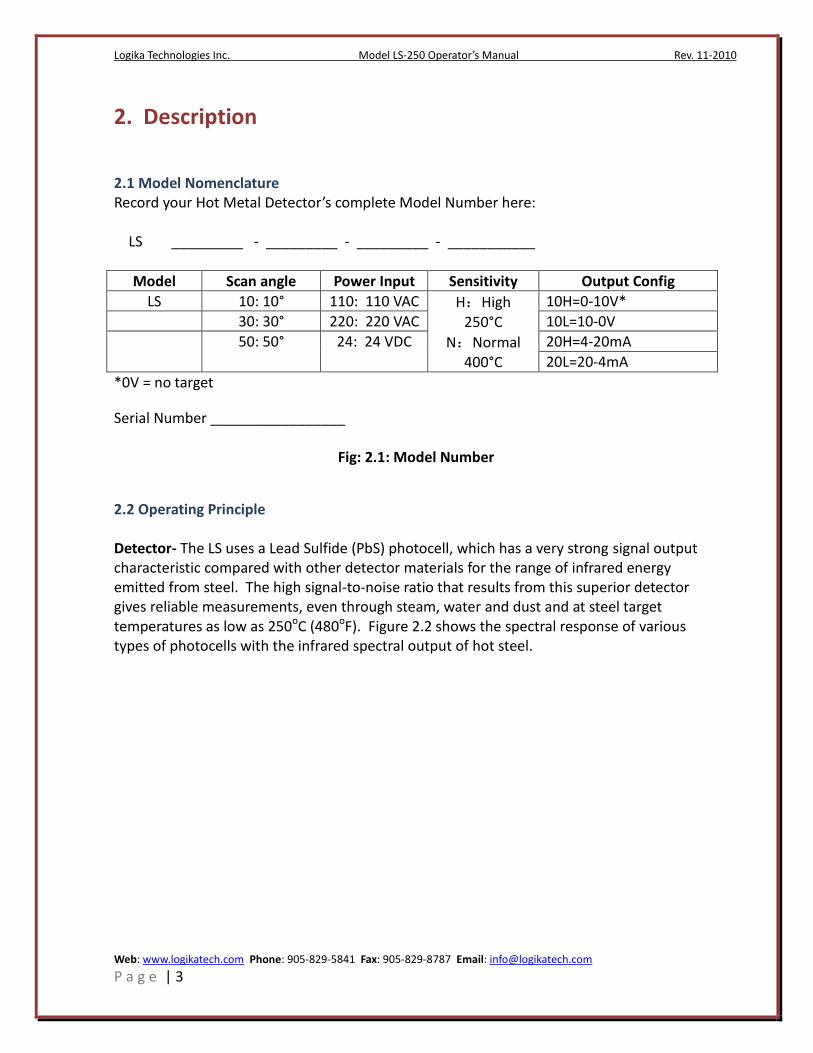
2.1 Model Nomenclature Record your Hot Metal Detector’s complete Model Number here: LS _________ - _________ - _________ - ___________
Model Scan angle Power Input Sensitivity Output Config
LS 10: 10° 110: 110 VAC H:High 250°C
N:Normal 400°C
10H=0-10V*
30: 30° 220: 220 VAC 10L=10-0V
50: 50° 24: 24 VDC 20H=4-20mA
20L=20-4mA
*0V = no target Serial Number _________________
Fig: 2.1: Model Number
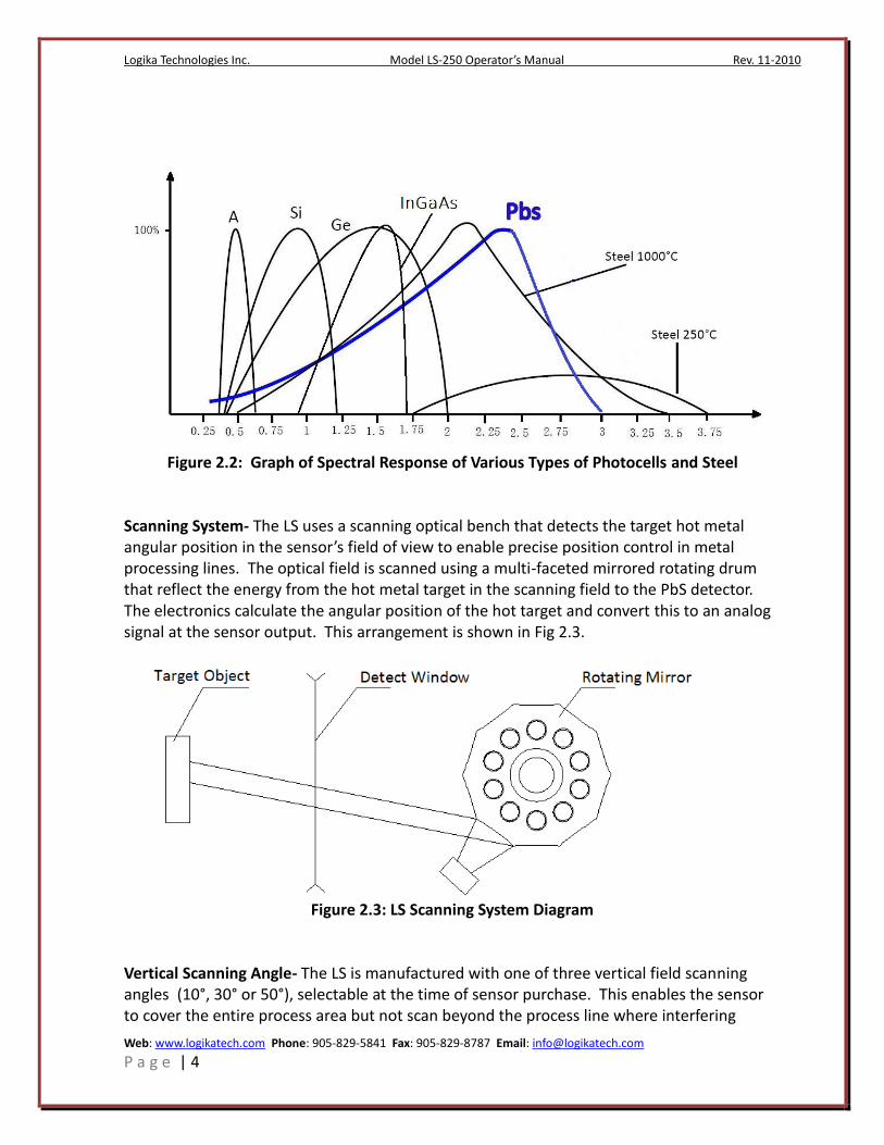
2.2 Operating Principle Detector- The LS uses a Lead Sulfide (PbS) photocell, which has a very strong signal output characteristic compared with other detector materials for the range of infrared energy emitted from steel. The high signal-to-noise ratio that results from this superior detector gives reliable measurements, even through steam, water and dust and at steel target temperatures as low as 250oC (480oF). Figure 2.2 shows the spectral response of various types of photocells with the infrared spectral output of hot steel.
Logika Technologies Inc. Model LS-250 Operator’s Manual Rev. 11-2010
Web: www.logikatech.com Phone: 905-829-5841 Fax: 905-829-8787 Email: [email protected]
P a g e | 4
Figure 2.2: Graph of Spectral Response of Various Types of Photocells and Steel
Scanning System- The LS uses a scanning optical bench that detects the target hot metal angular position in the sensor’s field of view to enable precise position control in metal processing lines. The optical field is scanned using a multi-faceted mirrored rotating drum that reflect the energy from the hot metal target in the scanning field to the PbS detector. The electronics calculate the angular position of the hot target and convert this to an analog signal at the sensor output. This arrangement is shown in Fig 2.3.
Figure 2.3: LS Scanning System Diagram
Vertical Scanning Angle- The LS is manufactured with one of three vertical field scanning angles (10°, 30° or 50°), selectable at the time of sensor purchase. This enables the sensor to cover the entire process area but not scan beyond the process line where interfering
Logika Technologies Inc. Model LS-250 Operator’s Manual Rev. 11-2010
Web: www.logikatech.com Phone: 905-829-5841 Fax: 905-829-8787 Email: [email protected]
P a g e | 5
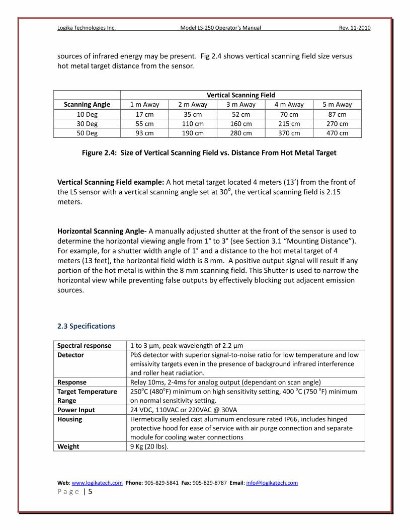
sources of infrared energy may be present. Fig 2.4 shows vertical scanning field size versus hot metal target distance from the sensor.
Vertical Scanning Field
Scanning Angle 1 m Away 2 m Away 3 m Away 4 m Away 5 m Away
10 Deg 17 cm 35 cm 52 cm 70 cm 87 cm
30 Deg 55 cm 110 cm 160 cm 215 cm 270 cm
50 Deg 93 cm 190 cm 280 cm 370 cm 470 cm
Figure 2.4: Size of Vertical Scanning Field vs. Distance From Hot Metal Target
Vertical Scanning Field example: A hot metal target located 4 meters (13’) from the front of the LS sensor with a vertical scanning angle set at 30o, the vertical scanning field is 2.15 meters. Horizontal Scanning Angle- A manually adjusted shutter at the front of the sensor is used to determine the horizontal viewing angle from 1° to 3° (see Section 3.1 “Mounting Distance”). For example, for a shutter width angle of 1° and a distance to the hot metal target of 4 meters (13 feet), the horizontal field width is 8 mm. A positive output signal will result if any portion of the hot metal is within the 8 mm scanning field. This Shutter is used to narrow the horizontal view while preventing false outputs by effectively blocking out adjacent emission sources.
2.3 Specifications Spectral response 1 to 3 µm, peak wavelength of 2.2 µm
Detector PbS detector with superior signal-to-noise ratio for low temperature and low emissivity targets even in the presence of background infrared interference and roller heat radiation.
Response Relay 10ms, 2-4ms for analog output (dependant on scan angle)
Target Temperature Range
250oC (480oF) minimum on high sensitivity setting, 400 oC (750 oF) minimum on normal sensitivity setting.
Power Input 24 VDC, 110VAC or 220VAC @ 30VA
Housing Hermetically sealed cast aluminum enclosure rated IP66, includes hinged protective hood for ease of service with air purge connection and separate module for cooling water connections
Weight 9 Kg (20 lbs).

Logika Technologies Inc. Model LS-250 Operator’s Manual Rev. 11-2010
Web: www.logikatech.com Phone: 905-829-5841 Fax: 905-829-8787 Email: [email protected]
P a g e | 6
3. Location and Mounting
3.1 Sensor Location The mounting distance between the LS sensor and hot metal target should enable the sensor’s field of view to cover the entire measuring area where the target may appear. The sensor scanning direction is from top to bottom of the vertical sensor field and its output corresponds to the first hot edge detected at the top of the scanning field. Mounting Distance- 1. Select an approximate sensor mounting distance from the hot metal target based on the following table. Consult Figure 3.1 on the size of the detection scanning field to help determine a good mounting distance for the configured scanning angle of your sensor (10o, 30o, or 50o) and to be sure that the distance that the sensor is mounted from the target will cover the entire process area. 2. For very hot processes the sensor mounting location should be far enough from the process line to protect the sensor from excessive heat. The maximum ambient temperature around the sensor without water cooling protection is 50oC (120oF). 3. For cooler target metal the sensor mounting location should be close enough to give the detector sufficient infrared energy to reliably detect the target. 4. The LS Sensor’s scanning plane should be vertical to the hot metal target.
Please see the following chart for LS Sensor mounting distance guidelines:
Target LS Sensor Mounting Distance
Product min (m)
max (m)
min (inch) max (inch)
Wire Rod 0.2 3 7.87 118.11 Bar 0.2 4 7.87 157.48 Billet 0.5 6 19.68 236.22 Blooms >2
>78.74 Strip Steel 0.6 2 23.62 78.74
Thin Plate 1 6 39.37 236.22 Thick Plate 1 8 39.37 314.96 Slab >2
>78.74

Logika Technologies Inc. Model LS-250 Operator’s Manual Rev. 11-2010
Web: www.logikatech.com Phone: 905-829-5841 Fax: 905-829-8787 Email: [email protected]
P a g e | 7
Figure 3.1 – LS sensor to target installation distance Interference- Background infrared radiation sources, such as other hot processes behind the target and reflected sunlight, should be minimized or eliminated: 1. Select the appropriate scanning angle when the sensor is ordered so that the sensor does not “over-scan” the target. This will minimize or eliminate sources of infrared interference behind the target hot metal. 2. The sensitivity potentiometer on the LS Sensor’s Control Panel can help eliminate sources of infrared interference. See the “Operation” chapter of this manual for additional details on sensitivity threshold adjustment. 3. Adjust the shutter at the front of the LS Sensor’s protective front cover to limit the field width. This will minimize or eliminate horizontal sources of infrared interference. 4. If necessary, install a background radiation screen between the target and the interference source to block its infrared energy from reaching the detector. 5. Choose a sensor location that minimizes excessive smoke and concentrated steam in the path between the sensor and target. If this is not possible then it is recommended that additional ventilation such as air curtains or fans be used to clear the area so the sensor can “see” the hot metal target.
3.2 Sensor Mounting Mounting Bracket- The LS has an adjustable mounting foot designed to allow for easy rotation through horizontal and vertical axes. The LS sensor is affixed to a support with a single 18 mm bolt through the LS Sensor’s base mounting stand. The support must be sufficiently rigid to absorb excessive site vibrations that could affect the precision or output of the detector. Air, Cooling Water Fittings- The LS has a water-cooling jacket and an air-purged hood for protection of the window glass. These sensors can be used in harsh environments with high temperatures, steam, dust and smoke. Please see Section 4.2 Plumbing Connection and Section 4.3 Air-Purge Connection for further details on installing these provisions for your sensor.
4. Utility Connections
4.1 Electrical Connections Electrical Overview- All electrical connections (power and signal) to the LS are made via a 15-pin connector with ground. The sensor is supplied with a mating connector at the back of its enclosure and a standard 2-meter cable with the quick-connect assembly mating to the

Logika Technologies Inc. Model LS-250 Operator’s Manual Rev. 11-2010
Web: www.logikatech.com Phone: 905-829-5841 Fax: 905-829-8787 Email: [email protected]
P a g e | 8
sensor and feruled wires for the junction box connections. Other cable lengths are available from Logika Technologies upon request. Cable Specification-
Multi-lead cable of 16 x 20 gauge (9 x 0.6 mm²) plus shielded 7 x 24 gauge (7 x O.34 mm²)
Teflon insulation for high temperature applications.
Outer metallic braid for mechanical protection.
Overall diameter of 9 mm.
Minimum bending radius of 30 mm.
Each lead is color-coded. Power Connections- Power Input (please specify power input at time of order).
White/Red, White/Brown 110VAC/60Hz
White/Black, White/Brown 220VAC/50Hz
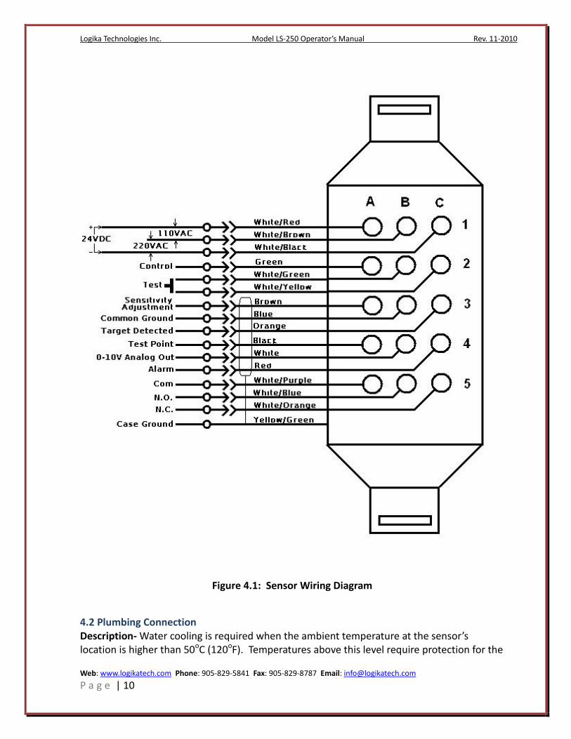
White/Red, White/Black DC24V Junction Box Wiring- Please see Figure 4.1 for the sensor wiring diagram. The supplied cable should be connected directly to the terminals of a junction box. All cables must be shielded all the way to the console with the shield connected to ground to eliminate electrical noise. Any unused output wires must have insulation protection or be connected to a free terminal of junction box. Power Connections- Power Input (please specify power input at time of order).
White/Red, White/Brown 110VAC/60Hz
White/Black, White/Brown 220VAC/50Hz
White/Red, White/Black DC24V Voltage Output- 0-10 VDC/10 mA, <100 mV ripple, proportional to angular position of hot metal in target field.
Transistor Static Output: Push-pull output maximum current 100 mA, output voltage 0 VDC or 24 VDC
Output Response time: o 10 degree scanning field: 2ms o 30 degree scanning field: 2ms o 50 degree scanning field: 4ms
Relay Output- Single-pole double throw contact, contact capacity rating is 250VAC/10A, relay operating time = 7.5 ms, relay release time = 3 ms. Note: Static output and Relay output are isolated, which means two types of outputs may be used, separately or both at the same time.

Logika Technologies Inc. Model LS-250 Operator’s Manual Rev. 11-2010
Web: www.logikatech.com Phone: 905-829-5841 Fax: 905-829-8787 Email: [email protected]
P a g e | 9
Sensor Diagnostics Outputs- Relay and voltage signals to indicate sensor conditions. 1. Control Output: Normally 24V, a 0VDC diagnostic alarm indicates dust or vapor interference on glass, target temperature drop, or signal saturating. 2. Alarm Output: Normally 24V, a 0VDC diagnostic alarm indicates no power input, scan motor abnormal, or interior housing temperature is higher than 55oC (130oF). 3. Signal Amplitude Output: Signal amplitude is an analog voltage signal, 0-13.5 VDC, proportional to the photocell output. This signal may indicate that the sensor’s protective glass lens requires cleaning or that the detector sensitivity needs to be increased. Signal amplitude strength is influenced by:
Installation position and location of sensor in process
Size of the target
Temperature of the target
Distance between the sensor and the target
Vapor in the field
Dust on the lens
Sensitivity Adjustment Setting 4. Test Point: Used to compare reference pulse with signal pulse during manufacture. 5. Sensitivity Adjustment: A 5k potentiometer may be connected between this point and Common to enable remote adjustment of sensitivity. Note that if this feature is used, the local sensitivity pot at the back of the instrument must be turned to Minimum.
Logika Technologies Inc. Model LS-250 Operator’s Manual Rev. 11-2010
Web: www.logikatech.com Phone: 905-829-5841 Fax: 905-829-8787 Email: [email protected]
P a g e | 10
Figure 4.1: Sensor Wiring Diagram
4.2 Plumbing Connection Description- Water cooling is required when the ambient temperature at the sensor’s location is higher than 50oC (120oF). Temperatures above this level require protection for the

Logika Technologies Inc. Model LS-250 Operator’s Manual Rev. 11-2010
Web: www.logikatech.com Phone: 905-829-5841 Fax: 905-829-8787 Email: [email protected]
P a g e | 11
electronics. A standard cooling water fitting is available at the sensor enclosure and copper heat exchanger tubing is embedded in the sensor housing to facilitate efficient heat removal from the sensor using circulating cooling water. Cooling water allows the sensor to be placed in ambient temperatures up to 120oC (250oF). Cooling Water Requirements
Clean industrial water
Maximum water inlet temperature of 25oC (77oF).
Maximum water pressure of 4 bars (60 psi)
Water flow rate of 1 to 2 L/min (0.26 to 0.53 gal/min) Connection- Use 3/8” flexible hose to connect the plant’s cool water supply to the sensor cooling water fitting and secure with a hose clamp. Refer to Figure 4.2, Ambient Temperature vs. Water Flow Rate Graph, to determine the cooling water flow rate for the ambient around the sensor.
Figure 4.2: Ambient Temperature vs. Water Flow Rate
4.3 Air Purge Connection Description- Compressed plant air can be used to prevent dust and vapor from entering the protective shroud around the lens of the sensor. Using plant air with the sensor will reduce lens cleaning maintenance and prolong sensor life where dust or corrosive vapors are present. Compressed Air Requirements

Logika Technologies Inc. Model LS-250 Operator’s Manual Rev. 11-2010
Web: www.logikatech.com Phone: 905-829-5841 Fax: 905-829-8787 Email: [email protected]
P a g e | 12
Must be clean, dry air free of contaminants and oil. Poor purge air quality will lead to dirty glass which may decrease sensor performance and increase sensor maintenance. Air filtration prior to the sensor purge inlet fitting is recommended for purge air of questionable quality.
Air Pressure range of 50 to 200 g/cm2
Air Flow rate of 4 to 16 L/min (0.14 to 0.56 ft/min) Connection- Connect the plant purge air to the air purge fitting on the sensor’s lens shroud using a ¼” air line. The purge air escapes out of the sensor shroud and dissipates into the environment.
Logika Technologies Inc. Model LS-250 Operator’s Manual Rev. 11-2010
Web: www.logikatech.com Phone: 905-829-5841 Fax: 905-829-8787 Email: [email protected]
P a g e | 13
5. Operation
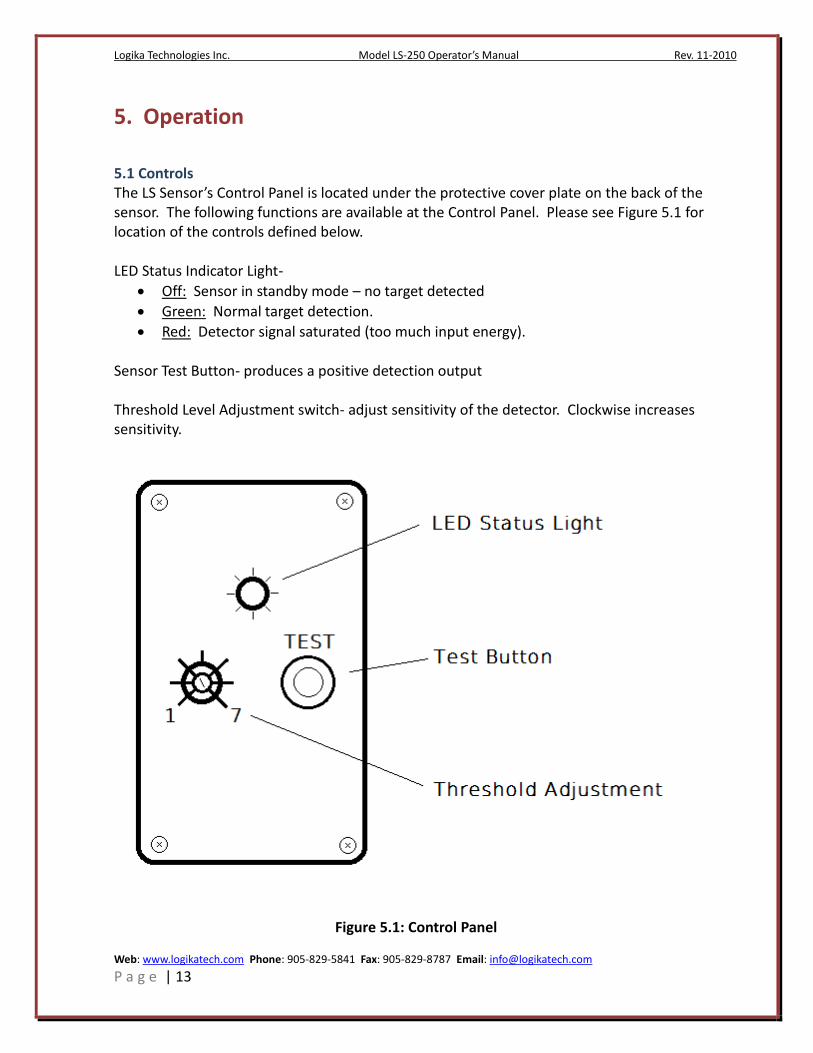
5.1 Controls The LS Sensor’s Control Panel is located under the protective cover plate on the back of the sensor. The following functions are available at the Control Panel. Please see Figure 5.1 for location of the controls defined below. LED Status Indicator Light-
Off: Sensor in standby mode – no target detected
Green: Normal target detection.
Red: Detector signal saturated (too much input energy). Sensor Test Button- produces a positive detection output Threshold Level Adjustment switch- adjust sensitivity of the detector. Clockwise increases sensitivity.
Figure 5.1: Control Panel
Logika Technologies Inc. Model LS-250 Operator’s Manual Rev. 11-2010
Web: www.logikatech.com Phone: 905-829-5841 Fax: 905-829-8787 Email: [email protected]
P a g e | 14
5.2 Threshold Level Adjustment 1. The LS includes a Threshold Level Adjustment. The user adjusts the Threshold Level Switch on the sensor control panel at installation to determine the base detector signal according to the application requirements. If greater sensitivity is required for the application then adjust the width of the shutters at the front of the sensor outward to allow more infrared energy to reach the detector
5.3 Test Function To test the electrical integrity of the LS sensor, follow the steps below:
1. Connect power to the sensor. 2. Press and hold the “TEST” button on the control panel when hot metal is not in the
target field of the sensor. The LED on the Control Panel should turn on (green). The test button simulates a positive signal from the detector. It will also actuate the sensor’s relay output (close the alarm circuit) to test the control function in your system as long as the test button is pressed.
3. Release the test button to return to normal operation and end the test function.
5.4 Troubleshooting No Target Detection- If the LED does not turn green when a hot metal target is in the LS Sensor’s field of view, there are two possibilities: 1. The Horizontal Scanning Angle Shutter located at the front of the sensor is not allowing sufficient radiation to reach the PbS sensor. Manually adjust the shutter to allow the target’s infrared energy to reach the detector. 2. The threshold switch is set incorrectly, select the alternate setting. False Target Detection- if a target is detected when no process material is in the scanning field check for background sources of radiation and eliminate them where possible and/or adjust the shutter opening by incrementally closing the shutters until the problem has been resolved.
Logika Technologies Inc. Model LS-250 Operator’s Manual Rev. 11-2010
Web: www.logikatech.com Phone: 905-829-5841 Fax: 905-829-8787 Email: [email protected]
P a g e | 15
Diagnostic Signal Output Detected- Check the diagnostic signals available and their status indication (see Section 4.1 Sensor Diagnostic Outputs for details). Correct fault conditions as necessary. See additional notes below:
No Power- Check that the sensor wiring connections are correct, that the connections are secure and tight and that the power supply is proper and normal.
Terminals 4C/3B normally will output a signal of 24VDC. If the output goes to 0V between those terminals then check for the following conditions:
1. If the housing temperature is over 55oC (130oF), then water cooling must be used (see section 4.2). If water cooling is already in use, then check the water’s inlet temperature and for flow restrictions to the unit.
2. Scanning Error (motor error or circuit error) means that the rotating drum motor may have failed. Please contact Logika Technologies for resolution.
Terminals 2A/3B normally will output a signal of 24VDC. If the output goes to 0V between those terminals then check the Sensor front window for dirt. Should this not fix the issue switch the sensitivity adjustment to the other setting.
6. Maintenance
6.1 Regular Maintenance Normally, the LS does not require maintenance at a fixed period. However regular attention to the following will ensure steady operation of the sensor: Lens Cleaning- Routinely check the LS sensor’s glass for dust or oil residue. Open the lens shield board at the front of the sensor by unscrewing the fastening hardware on the shield and clean the glass with alcohol and lens paper or soft cloth. Adjustments- The threshold level sensitivity (see Section 5.2) and the light shutter at the front of the sensor may require occasional adjustment. The screw at the front of the sensor allows adjustment of the light shutter.

Logika Technologies Inc. Model LS-250 Operator’s Manual Rev. 11-2010
Web: www.logikatech.com Phone: 905-829-5841 Fax: 905-829-8787 Email: [email protected]
P a g e | 16
6.2 Returns of the LS Contact Logika at 1-888-8LOGIKA with the Serial Number of your sensor before you return our product. If we are unable to solve the problem by phone or email, we will then provide you with a return authorization number. Do not return the LS without an authorization number. If the product is out of warranty, we will provide a repair estimate and then complete the repairs after your approval.

Logika Technologies Inc. Model LS-250 Operator’s Manual Rev. 11-2010
Web: www.logikatech.com Phone: 905-829-5841 Fax: 905-829-8787 Email: [email protected]
P a g e | 17
7. LS Enclosure Dimensions
Logika Technologies Inc. Model LS-250 Operator’s Manual Rev. 11-2010
Web: www.logikatech.com Phone: 905-829-5841 Fax: 905-829-8787 Email: [email protected]
P a g e | 18
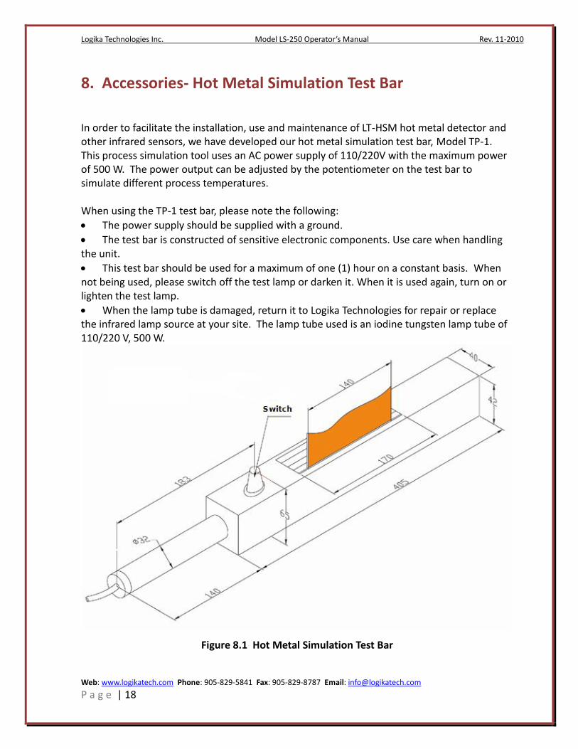
8. Accessories- Hot Metal Simulation Test Bar In order to facilitate the installation, use and maintenance of LT-HSM hot metal detector and other infrared sensors, we have developed our hot metal simulation test bar, Model TP-1. This process simulation tool uses an AC power supply of 110/220V with the maximum power of 500 W. The power output can be adjusted by the potentiometer on the test bar to simulate different process temperatures. When using the TP-1 test bar, please note the following:
The power supply should be supplied with a ground.
The test bar is constructed of sensitive electronic components. Use care when handling the unit.
This test bar should be used for a maximum of one (1) hour on a constant basis. When not being used, please switch off the test lamp or darken it. When it is used again, turn on or lighten the test lamp.
When the lamp tube is damaged, return it to Logika Technologies for repair or replace the infrared lamp source at your site. The lamp tube used is an iodine tungsten lamp tube of 110/220 V, 500 W.
Figure 8.1 Hot Metal Simulation Test Bar


![LOGIKA I TEORIJA SKUPOVA [2pt] Iskazna logika [2pt]nasport.pmf.ni.ac.rs/materijali/2105/LS-P01.pdf · Aristotel 384–322 BC Napomena ... Drugim recˇima, logika treba da utvrdi da](https://static.fdocuments.in/doc/165x107/5a76332e7f8b9a93088cf533/logika-i-teorija-skupova-2pt-iskazna-logika-2pt-aristotel-384322-bc-napomena.jpg)