![[5] Planetary gear and Mechanical paradox Gear design ...Eng).pdf · 1 [5] Planetary gear and Mechanical paradox Gear design system (English Version) Fig.5.1 Planetary gear and Mechanical](https://static.fdocuments.in/doc/165x107/5a78d0067f8b9aa17b8cf015/5-planetary-gear-and-mechanical-paradox-gear-design-engpdf1-5-planetary.jpg)
Model-Based Fault Diagnosis of a Planetary Gear: A Novel Approach Using Transmission Error · ·...
12
1830 IEEE TRANSACTIONS ON RELIABILITY, VOL. 65, NO. 4, DECEMBER 2016 Model-Based Fault Diagnosis of a Planetary Gear: A Novel Approach Using Transmission Error Jungho Park, Jong Moon Ha, Hyunseok Oh, Byeng D. Youn, Joo-Ho Choi, and Nam Ho Kim Abstract—Extensive prior studies aimed at the development of diagnostic methods for planetary gearboxes have mainly examined acceleration and acoustic emission signals. Recently, due to the rela- tionship between gear mesh stiffness and transmission error (TE), TE-based techniques have emerged as a promising way to analyze dynamic behavior of spur and helical gears. However, to date, TE has not been used as a measure to detect faults in planetary gears. In this paper, we propose a new methodology for model-based fault diagnostics of planetary gears using TE signals. A lumped paramet- ric model of planetary gear dynamics was built to extract simulated TE signals, while accounting for the planet phasing effect, which is a peculiar characteristic of the planetary gear. Next, gear dynamic analysis was performed using TE signals, and TE-based damage features were calculated from the processed TE signals to quan- titatively represent health conditions. The procedures described aforesaid were then applied to a case study of a planetary gear in a wind turbine gear train. From the results, we conclude that TE signals can be used to detect the faults, while enhancing under- standing of the complex dynamic behaviors of planetary gears. Index Terms—Condition monitoring, dynamic analysis, fault diagnosis, planetary gear, prognostics and health management. ACRONYMS AND ABBREVIATIONS AE Acoustic emission. FC Frequency center. FEA Finite element analysis. FM0 Figure-of-merit zero. GMS Gear mesh stiffness. P2P Peak-to-peak. RMS Root-mean-squares. TE Transmission error. TSA Time synchronous averaging. Manuscript received October 1, 2015; revised March 28, 2016; accepted July 7, 2016. Date of publication August 30, 2016; date of current version November 29, 2016. This work was supported in part by the Technology Innovation Program (10050980, System Level Reliability Assessment and Improvement for New Growth Power Industry Equipment) funded by the Ministry of Trade, Industry & Energy (MI, Korea) and in part by a grant from the Institute of Advanced Machinery and Design at Seoul National University (SNU-IAMD). (Corresponding authors: H. Oh and B. D. Youn.) Associate Editor: S. Bae. J. Park, J. M. Ha, H. Oh, and B. D. Youn are with the Department of Me- chanical and Aerospace Engineering, Seoul National University, Seoul 08826, South Korea (e-mail: [email protected]; [email protected]; hyunseok52@ gmail.com; [email protected]). J.-H. Choi is with the Department of Aerospace & Mechanical Engineering, Korea Aerospace University, Goyang 10540, South Korea (e-mail: jhchoi@ kau.ac.kr). N. H. Kim is with the Department of Mechanical and Aerospace Engineering, University of Florida, Gainesville, FL 32611 USA (e-mail: nkim@ufl.edu). Color versions of one or more of the figures in this paper are available online at http://ieeexplore.ieee.org. Digital Object Identifier 10.1109/TR.2016.2590997 NOTATION a i ith time data point. f Frequency of data. f g j Gear mesh frequency for its jth harmonic. F External force vector. k rp Time-varying GMS for the ring-planet meshes. k sp Time-varying GMS for the sun-planet meshes. [K] Stiffness matrix. l Total number of harmonics of gear mesh fre- quency. m Total number of data samples. [M] Mass matrix. p Circular pitch. q Displacement vector. ¨ q Acceleration vector. r s , r p , r r Pitch circle radii of sun, planet, and ring gears. s(·) Amplitude of a frequency component. T ( ref) rp Number of teeth in contact for the ring-planet meshes after applying the phase difference at the reference planet gear. ˜ T ( ref) rp Number of teeth in contact for the ring-planet meshes before applying the phase difference at the reference planet gear. T ( ref) sp Number of teeth in contact for the sun-planet meshes at the reference planet gear. x s , x p , x r Translational displacements of x-axis for sun, planet, and ring gears. y s , y p , y r Translational displacements of y-axis for sun, planet, and ring gears. z s , z p , z r Translational displacements of z-axis for sun, planet, and ring gears. Z s ,Z p ,Z r Number of sun, planet, and ring gear teeth. Δ rp Phase difference between ring-planet meshes. Δ rs Phase difference between sun-planet and ring- planet meshes. Δ sp Phase difference between sun-planet meshes. α s , α p , α r Rotational displacements of x-axis for sun, planet, and ring gears. β s , β p , β r Rotational displacements of y-axis for sun, planet, and ring gears. γ s , γ p , γ r Rotational displacements of z-axis for sun, planet, and ring gears. δ rs Difference of pitch points between ring-planet and sun-planet meshes. θ m Rotational angle of one mesh for the planet gear. μ Mean. σ Standard deviation. ϕ Pressure angle. 0018-9529 © 2016 IEEE. Personal use is permitted, but republication/redistribution requires IEEE permission. See http://www.ieee.org/publications standards/publications/rights/index.html for more information.
Transcript of Model-Based Fault Diagnosis of a Planetary Gear: A Novel Approach Using Transmission Error · ·...

1830 IEEE TRANSACTIONS ON RELIABILITY, VOL. 65, NO. 4, DECEMBER 2016
Model-Based Fault Diagnosis of a Planetary Gear:A Novel Approach Using Transmission Error
Jungho Park, Jong Moon Ha, Hyunseok Oh, Byeng D. Youn, Joo-Ho Choi, and Nam Ho Kim
Abstract—Extensive prior studies aimed at the development ofdiagnostic methods for planetary gearboxes have mainly examinedacceleration and acoustic emission signals. Recently, due to the rela-tionship between gear mesh stiffness and transmission error (TE),TE-based techniques have emerged as a promising way to analyzedynamic behavior of spur and helical gears. However, to date, TEhas not been used as a measure to detect faults in planetary gears.In this paper, we propose a new methodology for model-based faultdiagnostics of planetary gears using TE signals. A lumped paramet-ric model of planetary gear dynamics was built to extract simulatedTE signals, while accounting for the planet phasing effect, which isa peculiar characteristic of the planetary gear. Next, gear dynamicanalysis was performed using TE signals, and TE-based damagefeatures were calculated from the processed TE signals to quan-titatively represent health conditions. The procedures describedaforesaid were then applied to a case study of a planetary gear ina wind turbine gear train. From the results, we conclude that TEsignals can be used to detect the faults, while enhancing under-standing of the complex dynamic behaviors of planetary gears.
Index Terms—Condition monitoring, dynamic analysis, faultdiagnosis, planetary gear, prognostics and health management.
ACRONYMS AND ABBREVIATIONS
AE Acoustic emission.FC Frequency center.FEA Finite element analysis.FM0 Figure-of-merit zero.GMS Gear mesh stiffness.P2P Peak-to-peak.RMS Root-mean-squares.TE Transmission error.TSA Time synchronous averaging.
Manuscript received October 1, 2015; revised March 28, 2016; accepted July7, 2016. Date of publication August 30, 2016; date of current version November29, 2016. This work was supported in part by the Technology InnovationProgram (10050980, System Level Reliability Assessment and Improvementfor New Growth Power Industry Equipment) funded by the Ministry of Trade,Industry & Energy (MI, Korea) and in part by a grant from the Institute ofAdvanced Machinery and Design at Seoul National University (SNU-IAMD).(Corresponding authors: H. Oh and B. D. Youn.) Associate Editor: S. Bae.
J. Park, J. M. Ha, H. Oh, and B. D. Youn are with the Department of Me-chanical and Aerospace Engineering, Seoul National University, Seoul 08826,South Korea (e-mail: [email protected]; [email protected]; [email protected]; [email protected]).
J.-H. Choi is with the Department of Aerospace & Mechanical Engineering,Korea Aerospace University, Goyang 10540, South Korea (e-mail: [email protected]).
N. H. Kim is with the Department of Mechanical and Aerospace Engineering,University of Florida, Gainesville, FL 32611 USA (e-mail: [email protected]).
Color versions of one or more of the figures in this paper are available onlineat http://ieeexplore.ieee.org.
Digital Object Identifier 10.1109/TR.2016.2590997
NOTATION
ai ith time data point.f Frequency of data.fg
j Gear mesh frequency for its jth harmonic.F External force vector.krp Time-varying GMS for the ring-planet meshes.ksp Time-varying GMS for the sun-planet meshes.[K] Stiffness matrix.l Total number of harmonics of gear mesh fre-
quency.m Total number of data samples.[M] Mass matrix.p Circular pitch.q Displacement vector.q Acceleration vector.rs, rp, rr Pitch circle radii of sun, planet, and ring gears.s(·) Amplitude of a frequency component.T
(ref)rp Number of teeth in contact for the ring-planet
meshes after applying the phase difference at thereference planet gear.
T(ref)rp Number of teeth in contact for the ring-planet
meshes before applying the phase difference atthe reference planet gear.
T(ref)sp Number of teeth in contact for the sun-planet
meshes at the reference planet gear.xs, xp, xr Translational displacements of x-axis for sun,
planet, and ring gears.ys, yp, yr Translational displacements of y-axis for sun,
planet, and ring gears.zs, zp, zr Translational displacements of z-axis for sun,
planet, and ring gears.Zs, Zp, Zr Number of sun, planet, and ring gear teeth.Δrp Phase difference between ring-planet meshes.Δrs Phase difference between sun-planet and ring-
planet meshes.Δsp Phase difference between sun-planet meshes.αs, αp, αr Rotational displacements of x-axis for sun, planet,
and ring gears.βs, βp, βr Rotational displacements of y-axis for sun, planet,
and ring gears.γs, γp, γr Rotational displacements of z-axis for sun, planet,
and ring gears.δrs Difference of pitch points between ring-planet and
sun-planet meshes.θm Rotational angle of one mesh for the planet gear.μ Mean.σ Standard deviation.ϕ Pressure angle.
0018-9529 © 2016 IEEE. Personal use is permitted, but republication/redistribution requires IEEE permission.See http://www.ieee.org/publications standards/publications/rights/index.html for more information.

PARK et al.: MODEL-BASED FAULT DIAGNOSIS OF A PLANETARY GEAR: A NOVEL APPROACH USING TRANSMISSION ERROR 1831
ψn Circumferential angle of the nth planet countedin a counterclockwise manner and measured fromthe reference planet gear.
ω Helical angle.
I. INTRODUCTION
P LANETARY gears are widely used in many engineeringapplications, such as wind turbines and helicopter trans-
mission systems. As multiple planet gears can share a load, aplanetary gear has a unique advantage in systems, where the in-tensity of transmitted loads is extremely high. Therefore, plan-etary gears are usually exposed to severe loading conditions,which could lead to failures such as fatigue crack and pitting[1]. Unexpected failures of a gear may result in substantial eco-nomic losses and safety problems. Thus, fault detection anddiagnosis for planetary gears has received significant attentionin recent decades. Most currently available techniques weredeveloped by analyzing data from either vibration sensors oracoustic emission (AE) transducers.
Vibration-based techniques are currently the most widely ac-cepted methods for detecting faults in planetary gears because,as compared to AE-based techniques, they do not require expen-sive devices for measuring and processing signals. Numerousstudies have been conducted to identify efficient methods for an-alyzing vibration signals for planetary gear diagnostics. Barszczand Randall [2] developed a spectral kurtosis technique to detecttooth cracks in a planetary gear. This study demonstrated atechnique that can detect a tooth crack long before the gear fails.Lei et al. [3] proposed diagnostic features, such as the root meansquares of filtered signals, and the normalized summation ofpositive amplitudes of the difference spectrum after consideringthe unique behavior of the planetary gear. The adaptive optimalkernel method was proposed to account for the transient charac-teristics of the fault detection of the planetary gear [4]. Althoughsignificant progress has been made, there remain limitations ofvibration-based fault diagnostic methods. For example, envi-ronmental noise and mechanical resonance can easily disturbacceleration signals [5]. In addition, failure criteria in vibration-based methods rely on subjective engineering decisions, whichlack physical reasoning for differentiating the severity of afault [6].
AE-based techniques have also been developed for fault di-agnostics of planetary gears. Energy-based diagnostics features,such as kurtosis and crest factor of residual signals performedwell in detecting incipient faults in planetary gears [7]. To re-lieve the high cost in processing AE signals, the heterodynetechnique was developed [6]. Several studies reported that AEsignal-based methods are more sensitive to early fault detec-tion in gear systems as compared to methods utilizing vibrationsignals [6], [8]–[10]. However, AE-based techniques require ahigher sampling rate. Thus, they are expensive to implement.Additionally, AE transducers need to be located close to the sig-nal sources due to unwanted attenuation and noise, which canlimit the use of AE-based fault diagnosis techniques in actualfield applications [9].
Recently, transmission error (TE) has been investigated todetect tooth faults in a gear system [11], [12]. TE is defined asthe angular difference between the ideal position of the outputshaft of a gear drive without deflections and the actual positionof the output shaft [13]. The evaluation of gear mesh stiffness(GMS) relates the magnitude of TE to the severity of gear faults[14]–[16]. Prior works demonstrated that various faults can af-fect GMS and, eventually, TE [17], [18]. Taylor [11] processedTE signals of spur gears to extract features sensitive to faults.Taylor’s study examined spur gears made of acrylonitrile buta-diene styrene plastic; however, direct application of this study islimited because most spur gears are made of steel. Feki et al. [12]developed a three-dimensional dynamic gear model that simu-lates gear tooth pitting with GMS variations for helical gears.The authors showed the effectiveness of the gear model in de-tecting artificially injected faults of pitting. However, to the bestof our knowledge, all of the previous studies only focused oneither spur or helical gears. None of the prior work has studieda planetary gear, although planetary gears are widely used forpower conversion in transportation and wind turbines. A plan-etary gear, which consists of sun, ring, multiple planet gears,and a carrier, is known to show complex dynamic behaviors dueto the planet phasing effect. The planet phasing effect cannotbe found in other gears like spur and helical gears. Therefore,it is challenging to develop a model-based fault diagnosticsmethodology for planetary gears using TE-based techniques.This underscores the need to analyze the dynamic behavior ofTE generation in planetary gears, which in turn will enabledevelopment of an effective TE-based fault diagnostic method.
To address this gap, in this paper, we analyze the kineticsof a planetary gear system with a focus on determining theireffect on GMS and, ultimately, on TE. The goal of the studydescribed here is to develop an effective diagnostic method forplanetary gears. The paper is organized as follows. Section IIreviews the geometric characteristics of planetary gears and theeffect of planet phasing. In Section III, we develop a dynamicmodel for analysis of planetary gears, while accounting for thephasing effect to the change of GMS, which is used as an inputto calculate TE signals. Section IV verifies relevant features tomonitor the condition of planetary gears. To demonstrate theeffectiveness of the proposed diagnostic method, a case study ispresented in Section V. This paper concludes with a summaryand recommendations for future work.
II. REVIEW OF A PLANETARY GEAR
A planetary gear shows unique behaviors that cannot be foundin spur and helical gears. This section presents: 1) the geometriccharacteristics of the planetary gear; and 2) an overview of theplanet phasing effect.
A. Geometric Characteristics
A planetary gear is a gear system that consists of three typesof gears—a ring gear, a sun gear, and multiple planet gears—anda carrier on which the planet gears sit. As multiple planet gearsrotate around the sun gear, the planet gears share the load that the
1832 IEEE TRANSACTIONS ON RELIABILITY, VOL. 65, NO. 4, DECEMBER 2016
TABLE IWORKING CONDITIONS OF A PLANETARY GEAR
Sun Ring Planet Speed Direction
Condition 1 Stationary Driving Driven Decrease Same as inputCondition 2 Stationary Driven Driving Increase Same as inputCondition 3 Driving Stationary Driven Decrease Same as inputCondition 4 Driven Stationary Driving Increase Same as inputCondition 5 Driving Driven Stationary Decrease Reverse of inputCondition 6 Driven Driving Stationary Increase Reverse of input
system carries. In a planetary gear, ring, sun, and planet gearscan perform either as a driving component, a driven gear, or astationary supporter. Different working conditions of driving,driven, and stationary components are listed in Table I [19]. Asthe input speed to a planetary gear can be amplified positively ornegatively depending on the gear ratio, TE should be calculateddifferently to correspond with each working condition of theplanetary gear.
In a planetary gear, while the sun and the ring gears rotatearound their fixed axes, the axes of planet gears rotate aroundthe sun gear. The planet gears mesh with both the sun gear andthe ring gear while rotating around the sun gear. Due to thesecharacteristics, a planetary gear shows unique behaviors thatare not observed in gearboxes with fixed axes. These uniquecharacteristics include: 1) multiple planet meshing, 2) multi-ple and time-varying vibration transmission paths, 3) differentfrequency spectra from fixed axis gears (e.g., existence of side-bands in a healthy state), and 4) low operating speed due to thelarge gear ratio [20].
B. Planet Phasing Effect
Among the characteristics of the planetary gear described inSection II-A, multiple planet meshing has a significant impacton the dynamic behavior of planetary gears due to the planetphasing effect. The planet phasing effect was originally pro-posed as a design strategy that adjusts the number of teeth incontact between the sun-planet and ring-planet pairs in a plan-etary gear. This design strategy was empirically established toreduce the noise and vibration of the planetary gear [21]. Later,the effect of modifying the number of gear teeth on the reductionof unwanted vibration and noise was experimentally quantified[22]. Then, the mechanism defining how the planet phasing ef-fect could reduce the noise and vibration was identified usingthe force relationship between multiple meshes [23]. In anotherstudy, the geometric characteristics of the planetary gear withthe planet phasing effect were analyzed and the phase differencewas calculated using the geometry of the planetary gear [24].
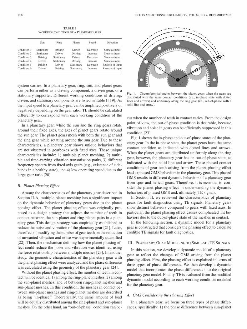
Without the planet phasing effect, the number of teeth in con-tact will be identical 1) among the ring-planet meshes, 2) amongthe sun-planet meshes, and 3) between ring-planet meshes andsun-planet meshes. In this condition, the meshes in contact be-tween sun-planet meshes and ring-planet meshes are describedas being “in-phase.” Theoretically, the same amount of loadwill be equally distributed among the ring-planet and sun-planetmeshes. On the other hand, an “out-of-phase” condition can oc-
Fig. 1. Circumferential angles between the planet gears when the gears aredistributed with the same contact conditions (i.e., in-phase state with dottedlines and arrows) and uniformly along the ring gear (i.e., out-of-phase with asolid line and arrow).
cur when the number of teeth in contact varies. From the designpoint of view, the out-of-phase condition is desirable, becausevibration and noise in gears can be efficiently suppressed in thiscondition [23].
Fig. 1 shows the in-phase and out-of-phase states of the plan-etary gear. In the in-phase state, the planet gears have the samecontact condition as indicated with dotted lines and arrows.When the planet gears are distributed uniformly along the ringgear, however, the planetary gear has an out-of-phase state, asindicated with the solid line and arrow. These phased contactconditions of gear teeth arising from the planet phasing effectlead to phased GMS behaviors in the planetary gear. This phasedGMS results in different dynamic behaviors of a planetary gearfrom spur and helical gears. Therefore, it is essential to con-sider the planet phasing effect in understanding the dynamicbehaviors of phased GMS and, ultimately, TE signals.
In Section II, we reviewed the characteristics of planetarygears for fault diagnostics using TE signals. Planetary gearsshow distinct behaviors compared to gears with fixed axes. Inparticular, the planet phasing effect causes complicated TE be-haviors due to the out-of-phase state of the meshes in contact.
In the following section, a dynamic model for a planetarygear is constructed that considers the phasing effect to calculatecredible TE signals for fault diagnostics.
III. PLANETARY GEAR MODELING TO SIMULATE TE SIGNALS
In this section, we develop a dynamic model of a planetarygear to reflect the changes of GMS arising from the planetphasing effect. First, the phasing effect is explained in terms ofthree types of phase differences. We then develop a dynamicmodel that incorporates the phase differences into the originalplanetary gear model. Finally, TE is evaluated from the modifieddynamic model according to each working condition modeledfor the planetary gear.
A. GMS Considering the Phasing Effect
In a planetary gear, we focus on three types of phase differ-ences, specifically: 1) the phase difference between sun-planet

PARK et al.: MODEL-BASED FAULT DIAGNOSIS OF A PLANETARY GEAR: A NOVEL APPROACH USING TRANSMISSION ERROR 1833
Fig. 2. Representative contact points in the sun-planet and ring-planet meshwith respect to planet gear rotation and the number of teeth in contact: thenumber of teeth in contact (a) with the sun-planet mesh for the reference planet,(b) with the sun in the sun-planet mesh for the first planet from the referenceplanet, (c) with the ring-planet mesh for the reference planet, and (d) with thering-planet mesh for the first planet from the reference planet. Phase differencesare illustrated between sun-planet meshes [(a) and (b)]; between sun-planet andring-planet meshes [(b) and (c)]; and between ring-planet meshes [(c) and (d)].
meshes, 2) the phase difference between the sun-planet meshesand the ring-planet meshes, and 3) the phase difference be-tween ring-planet meshes. As shown in Fig. 2, they correspondto Δspθm , Δrsθm , and Δrpθm , respectively. In this section, wewill briefly review how the three types of phase differences arederived, and then incorporate them into GMS.
1) Phase Differences between Sun-Planet Meshes: Phasedifferences exist between planet gears when they are mesh-ing with a sun gear. The phase differences between sun-planetmeshes (=Δsp) are defined as [24]:
Δsp ={
(Zsψn )/2π, for clockwise planet rotation−(Zsψn )/2π, for counter-clockwise planet rotation
(1)where Zs is the number of sun gear teeth and ψn isthe circumferential angle of the nth planet counted in acounterclockwise manner and measured from the referenceplanet gear. The reference planet gear can be chosen randomlyas the planet gears are uniformly distributed along the circum-ference of the ring gear.
To illustrate the phase difference between sun-planet meshes,as shown in Fig. 2, gear tooth contact starts at B, and endsat E. In between these points, there are C, D, and P that cor-
respond to the beginning of single, double contact, and pitchpoint, respectively.
In Fig. 2(a) and (b), the phase differences are expressed withΔspθm, where θm is the rotational angle of one mesh for theplanet gear. The number of teeth in contact for the sun-planetmeshes of the planet gear T
(ref+1)sp (θ) adjacent to the refer-
ence planet gear is calculated by shifting that for the sun-planetmeshes at the reference planet (=T(ref)
sp (θ)) as much as the phasedifference between the sun-planet meshes (=Δsp). The phaseshift is performed based on each pitch point of the numberof teeth in contact. Consequently, the relationship between thenumbers of teeth in contact for adjacent sun-planet meshes canbe expressed in the following equation:
T (ref+1)sp (θ) = T (ref)
sp (θ − Δspθm) (2)
2) Phase Differences between Sun-Planet and Ring-PlanetMeshes: The phase difference, Δrs, can be computed by inves-tigating the geometry of the planetary gear. The basic conceptused to calculate the phase difference is to estimate the differ-ence of pitch points in the ring-planet and sun-planet meshes. Aswe can calculate the point when both ring-planet and sun-planetmeshes are in their pitch points, the difference of the pointsimplies the phase difference when it is converted into a fractionof the mesh period. A detailed explanation can be found in [24].Therefore, Δrs is calculated as follows:
|Δrs| = δrs/p (3)
where δrs is the difference of pitch points between ring-planetand sun-planet meshes, and p is the circular pitch. The sign ofΔrs can be determined based on the contact sequence. Therefore,the relationship between the number of teeth in contact for thereference sun-planet and ring planet mesh is
T (ref)rp (θ) = T (ref)
rp (θ − Δrsθm) (4)
where T(ref)rp and T
(ref)rp is the number of teeth in contact for
the ring-planet mesh before and after applying the phase differ-ence. The phase of T
(ref)rp is coincident with T
(ref)sp . The phase
difference can be applied as shown in Fig. 2(b) and (c).3) Phase Differences between Ring-Planet Meshes: Phase
differences between ring-planet meshes (= Δrp) are similarlydefined as follows:
Δrp ={
(Zrψn )/2π, for clockwise planet rotation−(Zrψn )/2π, for counter-clockwise planet rotation
(5)where Zr is the number of ring gear teeth.
The same rule is applied to the number of teeth in contactwith ring-planet meshes. The relationship between the numberof teeth in contact for first ring-planet meshes from the refer-ence planet (=T
(ref+1)rp (θ)) and reference ring-planet meshes
(=T(ref )rp (θ)) is expressed as follows:
T (ref+1)rp (θ) = T (ref)
rp (θ − Δrpθm) (6)
As shown in Fig. 2(c) and (d), the phase differences in termsof the fraction of the mesh period are expressed in Δrpθm .

1834 IEEE TRANSACTIONS ON RELIABILITY, VOL. 65, NO. 4, DECEMBER 2016
Fig. 3. Conversion from the number of teeth in contact (= T(n )rp ) to GMS
(= k(n )rp ) for the nth ring-planet mesh.
Fig. 4. Calculation of sun-planet GMS using (a) finite element analysis and(b) calculated values.
Many studies have shown that time-varying profiles of GMSat each tooth are subject to change due to variability of teeth,which include variations in things such as tip relief error andindexing error [25], [26]. In this study, however, we assumedthat the variability between different teeth is negligible and thetime-varying profiles of GMS are identical. Next, the number ofteeth in contact with the sun-planet (=Trp(θ)) and ring-planetmeshes (=Tsp(θ)) can be converted into a time-varying profileof GMS (see Fig. 3) because GMS fluctuates along with thenumber of teeth in contact [27].
The points B, C, D, E, and P in Fig. 3 coincide with theones in Fig. 2. Therefore, we can obtain the time-varying GMSfor the ring-planet (=krp(θ)) and sun-planet meshes (=ksp(θ))by incorporating magnitudes of GMS and geometrical informa-tion, which are essential factors that affect dynamic behaviorsof the gear. To obtain the magnitudes of GMS in one meshcycle of each sun-planet and ring-planet mesh, finite elementanalysis (FEA) or analytic methods can be used. While an an-alytic method is preferred for shorter computation time, FEAis known to produce more accurate results despite their longcomputation time [18], [28]. For example, Fig. 4 shows thecalculated profile of GMS for ring-planet mesh using FEA.When the calculated magnitudes of GMS are discretized astwo values with maximum and minimum values, they can beconverted into rectangular wave forms, like the one shown inFig. 3.
Fig. 5. Degrees of freedom for sun-planet and ring-planet gears.
B. Dynamic Model for a Planetary Gear
Dynamic models have been proposed by numerous studiesto investigate the dynamic behaviors of the planetary gear[29]–[32]. In this study, we adopt a dynamic model for aplanetary gear system originally proposed by Kim [32], andincorporate the phasing effect into the model. The magnitudesof GMS, ksp, and krp, in the stiffness matrix of the previousmodel, are modified using GMS obtained from the phasednumber of teeth in contact.
Kim’s model considered 12 degrees of freedom, includingrotations and translations about x-, y-, z-axes for sun-planet andring-planet relation. The model’s equation of motion is
[M ] {q} − [K] {q} = {F } (7)
where [M] is the mass matrix; q is the displacement vector; qis the acceleration vector; [K] is the stiffness matrix; and F isthe external force vector. As shown in Fig. 5, the displacementvectors for sun-planet and planet-ring gears are (xs , ys, zs, αs,βs, γs, xp, yp, zp, αp, βp, γp) and (xp, yp, zp, αp, βp, γp, xr,yr, zr, αr, βr, γr), respectively. This model could consider thehelix angle of gear teeth because it has 12 degrees of freedomand time-varying GMS can be included in stiffness components.The damping term can be ignored because the damping effectis not significant in characterizing the behavior of the planetarygear [33]. Among the aforesaid displacement vectors, this studyfocuses on the rotational displacements of the z-axis, γs, γp, andγr because we are focusing on the angular difference (i.e., TE).
The stiffness matrices for sun-planet and ring-planet gearsused in this study are represented in Appendix. By incorporatingthe profiles of GMS obtained from the tooth contact conditioninto (A1) and (A2) in Appendix, the dynamic model for theplanetary gear can be completed. The model has the 12 degreesof freedom. In this study, however, we only consider the rotatingmotion of the planetary gear.
C. TE in a Planetary Gear
TE can be calculated from the rotational displacements ofthe input shaft and the output shaft of the dynamic model. Asvarious inputs and outputs can be obtained from the planetarygear of the same configuration, as mentioned in Section II-A,TE in a planetary gear also could be calculated differently in

PARK et al.: MODEL-BASED FAULT DIAGNOSIS OF A PLANETARY GEAR: A NOVEL APPROACH USING TRANSMISSION ERROR 1835
Conditions 2, 4, and 6 using the rotational displacements of thez-axis outlined in Section III-B, as shown in the following [34]:
TE=
⎧⎨⎩
TE=γr − γc · (Zr +Zs)/Zr , for Condition 2TE=γs − γc · (Zr +Zs)/Zs , for Condition 4TE=γs +γr · (Zr/Zs), for Condition 6.
(8)
TE in Conditions 1, 3 and 5 can be calculated when input andoutput components are reversed from Conditions 2, 4 and 6. InKim’s modeling, however, the carrier motion is not considered.Therefore, we calculate the carrier rotation using planet rotation.It is defined as follows:
γc = γs + γp · Zp/(Zr − Zp) (9)
where Zp is the number of planet teeth, and γc is the rotationaldisplacement of the carrier.
In this section, the profiles of GMS were calculated consid-ering the planet mesh phasing that makes phase differences ineach profile of GMS for the ring-planet mesh and the sun-planetmesh. Then, the dynamic model of a planetary gear was con-structed with the phased profiles of GMS for the sun-planet andring-planet gears. From the constructed dynamic model, we cancalculate TE using the rotation of input and output motion whileaccounting for the planet mesh phasing. After calculating TE ateach time step, the time series of TE should be quantitativelyreshaped after signal processing techniques are performed forfault diagnostics.
IV. FEATURE EXTRACTION FOR DETECTING FAULTS WITH TE
TE generally shows periodic behaviors due to repeated shapesof GMS. In a planetary gear, TE is also affected by phase dif-ferences among the gears that come from multiple planet gearsmeshing with the sun and ring gears. This section explains pre-processing techniques that are used to alleviate the complexityof the peculiar TE signals in planetary gears. Then, TE-basedfeatures are extracted from the processed signals to classify thenormal and abnormal states.
A. Preprocessing of TE
Fig. 6 shows the preprocessing procedures for TE signals thatcan be used to extract TE-based features. The procedures aremade up of three steps that can reveal characteristic behaviors ofthe planetary gear in the time domain and the frequency domain.First, the offset from zero is subtracted from the TE signal. Dueto deflection of the gear teeth, it is beneficial to subtract the meancomponent of the TE signal for sensitivity enhancement. Next,the shifted signals are resampled based on gear rotation, whichis called angular resampling. In the resampling process, linear,bandwidth linear, and spline interpolation methods can be used[35]. After resampling, the effects of GMS on TE in the timedomain can be easily identified as TE is represented in an an-gular domain. Also, the resampling can increase consistency indata. A noise reduction technique such as time synchronous av-eraging (TSA) can be used to further enhance the signal-to-noiseratio [36]. Last, frequency components of TE signals are ana-lyzed using FFT. This procedure can identify the characteristicbehavior in the frequency domain from multiple planet phas-
Fig. 6. Preprocessing procedures for TE signals: (a) raw TE signals, (b) mean-subtracted TE signals, (c) TSA signals resampled based on planet rotation, and(d) order analysis results.
ing effects. The frequency analysis may be performed beforethe resampling process. However, when the frequency analysisis performed after the resampling process, we can observe thefrequency components per gear rotation, which enables orderanalysis and minimizes the effects of variable rotating speed.
B. TE-Based Feature Extraction
The TE-based features are extracted from the processed TE toquantify the health state of the system. In this study, root-mean-squares (RMS), kurtosis, frequency center (FC), and figure-of-merit zero (FM0) are used. Formulations of the features arelisted in Table II.
In Table II, ai is the ith time data point, m is the total numberof data samples, μ is the mean of the data, σ is the standarddeviation of the data, f is the frequency of the data, s(f) is theamplitude of the frequency components, P2P is the peak-to-peak (P2P) value of the data, fg
j is gear mesh frequency andits jth harmonics, and l is the total number of harmonics. Thefirst two are time-domain features, the third is a frequency-domain feature, and the last is a time-domain feature that usesfrequency-domain information.
The RMS is well-known for quantifying the overall degra-dation degree of the system in the time domain [37], albeitinsensitive to incipient failure. In this study, the RMS is adoptedto evaluate relative sensitivity to faults through comparison withother features. The kurtosis measures the peakedness of a dis-tribution with respect to normal distribution and the tail thick-ness [38]. Kurtosis is used to show degree of the TE signal’sdeviation from the mean value due to the fault of the gear. The

1836 IEEE TRANSACTIONS ON RELIABILITY, VOL. 65, NO. 4, DECEMBER 2016
TABLE IIDEFINITION AND PHYSICAL INTERPRETATION OF TE-BASED FEATURES
RMS Kurtosis FC FM0
Definition
√1m
m∑i = 1
a2i
∑ mi = 1 [ai − μ ]4
m × (σ 2 )2
∫+ ∞0 f · s(f )df
∫+ ∞0 s(f )df
P 2P∑ lj = 1 s(f g
i )
Physicalinterpretation
Overall kinetic energy level Deviating levels of signals withrespect to normal distribution
Mean of the frequency components Relative amplitude of peak-to-peak(P2P) values to meshing harmonics
TABLE IIISPECIFICATION OF THE PLANETARY GEAR IN A WIND TURBINE GEAR TRAIN
USED IN THIS STUDY [38]
Gear data Sun gear Planet gear Ring gear
Number of teeth 16 26 68Pressure angle (degree) 24.6 24.6 24.6Module (mm) 14.0 14.0 14.0Pitch circle diameter (mm) 224 364 952Root diameter (mm) 202 329 980Transverse tooth thickness (mm) 25.0 18.5 25.0Face width (mm) 180 180 180
FC calculates the mean of the frequency component and is usedto observe the transition of the main frequency components. Asgear faults are known to induce phase modulation [5], the FCcan show how the faults affect the frequency components of thesystem. The FM0 is calculated by dividing the P2P value of thesignals by the sum of the amplitude of the gear mesh frequency.The FM0 is known to detect localized faults in the measuredsignal [39]. The FM0 indicates the increase of magnitude of TEby calculating P2P values and the reduction in amplitude of themain frequency due to the fault signal.
V. CASE STUDY
This section presents a case study to demonstrate the ef-fectiveness of TE for fault diagnostics using the techniques pre-sented in Sections III and IV. The specifications of the planetarygear that we adopted in this study are shown in Table III [40].Condition 4 (planet-driving and sun-driven) is used with thedriving speed of 30 r/min and the applied torque of 180 kN · m.Additionally, we assumed a clockwise input, clockwise output,and a counterclockwise planet rotation. We adopted GMS resultsfrom a finite element analysis of an actual planetary gear train ina wind turbine. The finite element code developed by Vijayakar[41], [42] was used to calculate the time-varying GMS; its re-sponse was validated by other studies [23], [40], [43]. Giventhe above conditions, we obtained fault features using the TEcalculated from the proposed dynamic model of the planetarygear considering the phasing effect.
A. Calculation of TE From the Dynamic Model of thePlanetary Gear
TE of the planetary gear can be calculated by following theprocedures described in Section III. To obtain time-varyingGMS, the phase differences between sun-planet meshes (=Δsp)
Fig. 7. GMS for one mesh of (a) first sun-planet gear, (b) second sun-planetgear, (c) third sun-planet gear, (d) first ring-planet gear, (e) second ring-planetgear, and (f) third ring-planet gear with phase differences considered.
and ring-planet meshes (=Δrp) were calculated for a planetarygear with a counterclockwise planet rotation using (1) and (5),found in Section III-A. The calculated values of the phase dif-ferences were 68/3 and -16/3. They were converted into 2/3,as the phase differences are not affected by the integer compo-nent. From the previous study [40], the maximum and minimummagnitudes of GMS for the sun-planet mesh were determinedto be 2.7 × 10⁹ and 4.2 × 10⁹ N/mm, respectively. Likewise,the maximum and minimum magnitudes of GMS for the ring-planet mesh are 3.7 × 10⁹ and 5.7 × 10⁹ N/mm, respectively.In Fig. 7(a)–(c), the profiles of GMS for sun-planet meshes areshown for one mesh with phase differences considered. Also,Fig. 7(d)–(f) shows the phased profiles of GMS for ring-planetmeshes.
Next, the phase difference between the sun-planet and thering-planet mesh (=Δrs) was calculated using (3). The cal-culated absolute value is 0.625 and has a positive sign bythe contact sequence. The calculated profiles of GMS duringone mesh with the phase differences are shown in Fig. 7. Thephase differences are considered between Fig. 7(a) and (d),Fig. 7(b) and (e), and Fig. 7(c) and (f).
For this study, we also parameterized time-varying profilesof GMS in a faulty state. The relationship between the profilesof GMS and gear faults has been investigated comprehensively[17], [18], [44]. Pandya and Parey [44] showed that a crack of30% of a tooth’s root induced about 10% decrease of GMS. Inthis research, we assumed three levels of faults resulting in 10%,20%, and 30% decreases of the GMS. Although a crack fault

PARK et al.: MODEL-BASED FAULT DIAGNOSIS OF A PLANETARY GEAR: A NOVEL APPROACH USING TRANSMISSION ERROR 1837
Fig. 8. (a) Illustration of the rotation of a faulty planet gear and (b) its influenceon time-varying GMS of ring-planet and sun-planet meshes (indicated withdotted squares).
was considered in this case, faults like spalls and breakage arealso known to induce the decreases of GMS [17]. It was revealedthat the GMS shows different reduction behaviors under faultsof spalls and cracks [45]. Therefore, it is possible to detect anddifferentiate the failure modes by monitoring the TE in gearsystems. Consequently, the overall behaviors of TE from othertypes of faults are expected to be similar.
Also, we assumed that the faults exist in a planet gear. Afaulty tooth in a planet gear would contact with both a sun anda ring gear repeatedly in a half-planet rotation. Therefore, thestiffness reductions appear with a phase difference equal to ahalf-planet rotation (like that shown in Fig. 8). In Fig. 8(b), thefaulty tooth of the planet gear was parameterized by reducingthe magnitudes of GMS in time-varying profiles of GMS. Thephase difference of faulty time-varying GMS is a half-planetrevolution.
Then, the time-varying profiles of GMS in normal and faultygears were parameterized into a dynamic model, as describedin Section III-B. As the planetary gear used in this study is aspur planetary gear, we ignored the translational displacementsin the x- and y-axes, which are related to a helical angle. Afterinserting the geometrical values and working condition into (7),the TE of the planetary gear was calculated according to (8)with the Condition 4, as outlined in Section III-C.
B. Results of Processed TE
Using the signal processing techniques developed inSection IV-A, TE signals calculated in Section V-A were pro-cessed to effectively observe the behaviors of the gear in thetime and frequency domains. Before analyzing the behaviors ofTE from the planetary gear with the phasing effect, however, we
Fig. 9. TE of the planetary gear with an in-phase state: (a) resampled TE perone planet rotation and (b) the result of order analysis before incorporating thephasing effect.
Fig. 10. TE of the planetary gear with an out-of-phase state: (a) resampledTE per one planet rotation and (b) the result of order analysis.
first observed the behavior of TE before the phasing effect wasincorporated. Fig. 9 shows the TE of the planetary gear with anin-phase state. Fig. 9(a) shows periodic behaviors of resampledTE per one planet rotation. Fig. 9(b) describes the result of or-der analysis of the TE signals. The frequency of the periodicmotions in one planet rotation is the number of teeth of a planetgear (i.e., 26). The existence of the frequency was confirmedby the order analysis results, as shown in Fig. 9(b). Fig. 10shows TE results when the phasing effect is incorporated. It wasobserved that the amplitudes became smaller compared to thecase with the in-phase state. Also, the frequency of the periodicmotion became higher, specifically 78. This increase happensfrom sequential meshing of planets due to planet mesh phasing.Without planet mesh phasing, the three planets would contactsimultaneously with the ring and sun gears, and order analy-sis results would show harmonics of the planet tooth numberlike those shown in Fig. 9(b). However, as the phase differencesfrom planet mesh phasing make the time difference planets con-tact with the ring and sun gears, the order analysis results showharmonics of three times the planet tooth number.
Fig. 11 shows TE results from the faulty planetary gears.TE from a faulty gear shows two different heights of sparkswith a phase about 180°. These sparks happen due to a fault inthe planet gear. As the planet gear with a fault rotates aroundthe sun gear, the faulty tooth will contact with sun and ringgear repeatedly. Also, two different heights of sparks happenbecause the different magnitude of GMS for the ring-planetand sun-planet mesh induces a different reduction of GMS ineach gear mesh. In order analysis results of a faulty gear, thereappear low-frequency components and sidebands near the main

1838 IEEE TRANSACTIONS ON RELIABILITY, VOL. 65, NO. 4, DECEMBER 2016
Fig. 11. TE of the faulty planetary gear with an out-of-phase state: (a) resam-pled TE per one planet rotation and (b) the result of order analysis.
Fig. 12. (a) RMS, (b) kurtosis (c) FC and (d) FM0 values from a normal andfaulty planetary gear at various torques (30, 60, 120, 180, 240 kN · m) with adriving speed of 30 r/min.
harmonics. These sidebands are due to two sparks of TE in thetime-domain signal. This result is consistent with reports in theliterature of studies using vibration signals and TE signals in afaulty gear [12], [17], [46].
C. Calculated Features in Various Operating Conditions
Four TE-based features described in Section IV-B were cal-culated using processed TE in various torques (30, 60, 120, 180,and 240 kN · m) and fault sizes (70%, 80%, and 90% of originalmagnitude of GMS). These calculations were performed to findout how the features change along the given operating condi-tions. For change of a torque, we investigated the robustnessof the features in different operating conditions. As differentmagnitudes of torque are expected to change the amplitude ofTE, we could notice how each feature behaves at varying con-ditions. For the change of magnitude of GMS, we could noticewhether each feature could differentiate fault size. As differentmagnitudes of GMS imply different sizes of a tooth fault, wecould, therefore, investigate the relationship between featuresand fault sizes. Figs. 12 and 13 show the calculated values offeatures at mentioned conditions.
Fig. 13. (a) RMS, (b) kurtosis, (c) FC, and (d) FM0 values from calculatedTE of different fault sizes.
First, we observed the behaviors of the features at torques of30, 60, 120, 180, and 240 kN ·m with a driving speed of 30 r/min.In the observation, 90% of GMS was chosen. In Fig. 12(a), RMSshows slightly higher value for a faulty case than a normal case.This result happens as the sparks in the TE take small portionsof the integrated signals. The integration makes RMS more de-pendent on magnitude of torque, rather than existence of faults.For the kurtosis in Fig. 12(b), the tail of the TE distributionbecomes thicker in a faulty case due to the sparked componentof TE in the time domain, which causes a higher value of kur-tosis. For the FC, the low-frequency components in Fig. 11(b)decrease the mean of the frequency component and make theFC value smaller. Therefore, classification between a normaland a faulty case is possible. An increase in P2P values from thespark at a faulty case makes the FM0 value larger; thus, we candiscriminate between normal and faulty cases. Kurtosis, FM0,and FC are more sensitive at all torque levels than RMS forclassification of the conditions between normal and abnormal.This result is because they are not calculated based on absolutemagnitude of TE signals.
Also, the features were calculated at 70%, 80%, 90%, and100% of normal GMS with a driving speed of 30 r/min and atorque of 180 kN · m. Fig. 13 shows that we can observe anincrease of RMS, kurtosis, and FM0, and a decrease of FC.Larger faults make the sparks of TE larger, while other TEsignals remain at their normal amplitude. This result makesRMS, kurtosis, and FM0 larger as a result of more severe faults.On the other hand, FC shows smaller values due to the magni-fied low-frequency components from the enlarged sparks. Theresults imply that the features calculated from processed TEcould have the potential to differentiate fault levels at differentoperating conditions because 1) kurtosis, FM0, and FC in faultystates show distinct values from normal ones at different torque

PARK et al.: MODEL-BASED FAULT DIAGNOSIS OF A PLANETARY GEAR: A NOVEL APPROACH USING TRANSMISSION ERROR 1839
magnitudes; and 2) these distinct values become severe as thefault sizes get bigger.
VI. CONCLUSION
This paper proposed model-based fault diagnostics for plan-etary gears using TE signals calculated from a dynamic modelwith phased GMS. This dynamic model for planetary gears wasdeveloped with a lumped parameter model. As the planet phas-ing effect was integrated into the model, GMS of the planetarygear was realistically calculated, which enabled credible calcu-lation of TE signals in normal and faulty states. Using this in-formation, we then identified the mesh phasing effect and faultyphase difference from the TE signals in the time and frequencydomain. Next, the signals were processed, and four TE-basedfeatures—RMS, kurtosis, FC, and FM0—were calculated. Weobserved that kurtosis, FC, and FM0 performed more robustlyacross various torque and fault levels than was observed forRMS.
The main advantages of TE for fault diagnostics of a planetarygear are as follows. First, TE can help increase our understand-ing of the dynamic behaviors of the planetary gear. From theTE, we can observe the effect of planet phasing, which has asignificant impact on the dynamic behavior of the gear. In theresults of order analysis from the planet gear, order componentsof three times the planet tooth number appear due to sequen-tial meshing of planet gears. Faulty phase difference of a halfrevolution arose in the TE signals due to meshing of the planetgear with the ring and sun gears. Moreover, it would be pos-sible to infer the location of faults by observing the resampledTE signals. Second, TE has potential to detect incipient faults
of gears and to differentiate fault levels. Vibration signals areknown to react only to severe faults and cannot differentiatefault level. As TE is directly related to mesh stiffness, it canreact sensitively with early faults. As gear faults like spalls andbreakage are known to affect GMS, the signal could also react toincipient faults of different varieties. However, TE shows depen-dency on magnitude of torque, which could lead to difficultiesin establishing the fault criteria. Therefore, it is recommendedto calculate TE-based features based on relative magnitudes ofTE, such as kurtosis, FM0, and FC, or to define different faultcriteria for each operating condition.
In this study, dynamic behaviors of a planetary gear wereinvestigated to develop a new fault diagnostics method using TEsignals. However, the proposed methods are at this point limitedto use in dynamic models of planetary gears and with simulatedTE signals. Therefore, our future work will include applicationof the proposed diagnostic methods to measured TE data fromtestbeds. With the measured TE data, we plan to compare TEchanges from the faults with those from the noise of operatingvariabilities. The GMS predicted by FEA will also be validated.Additionally, more advanced signal processing methods or TE-based features that can fully utilize characteristics of TE will beexplored in future studies.
APPENDIX
The stiffness matrices for sun-planet and ring-planet gearsare calculated using (A1) and (A2), where rs, rp, and rr are thepitch circle radii of the sun, planet, and ring gears, respectively;ϕ is the pressure angle; and ω is the helical angle.

1840 IEEE TRANSACTIONS ON RELIABILITY, VOL. 65, NO. 4, DECEMBER 2016
REFERENCES
[1] F. Chaari, T. Fakhfakh, and M. Haddar, “Dynamic analysis of a plane-tary gear failure caused by tooth pitting and cracking,” J. Failure Anal.Prevention, vol. 6, pp. 73–78, 2006.
[2] T. Barszcz and R. B. Randall, “Application of spectral kurtosis for detec-tion of a tooth crack in the planetary gear of a wind turbine,” Mech. Syst.Signal Process., vol. 23, pp. 1352–1365, 2009.
[3] Y. Lei, D. Kong, J. Lin, and M. J. Zuo, “Fault detection of planetarygearboxes using new diagnostic parameters,” Meas. Sci. Technol., vol. 23,p. 055605, 2012.
[4] Z. Feng and M. Liang, “Fault diagnosis of wind turbine planetary gear-box under nonstationary conditions via adaptive optimal kernel time–frequency analysis,” Renew. Energy, vol. 66, pp. 468–477, 2014.
[5] X. Fan and M. J. Zuo, “Gearbox fault detection using Hilbert and waveletpacket transform,” Mech. Syst. Signal Process., vol. 20, pp. 966–982,2006.
[6] Y. Qu, D. He, J. Yoon, B. Van Hecke, E. Bechhoefer, and J. Zhu, “Gearboxtooth cut fault diagnostics using acoustic emission and vibration sensors–acomparative study,” Sensors, vol. 14, pp. 1372–1393, 2014.
[7] K. R. Al-Balushi and B. Samanta, “Gear fault diagnosis using energy-based features of acoustic emission signals,” Proc. Inst. Mech. Eng., PartI: J. Syst. Control Eng., vol. 216, pp. 249–263, 2002.
[8] T. H. Loutas, G. Sotiriades, I. Kalaitzoglou, and V. Kostopoulos, “Con-dition monitoring of a single-stage gearbox with artificially induced gearcracks utilizing on-line vibration and acoustic emission measurements,”Appl. Acoust., vol. 70, pp. 1148–1159, 2009.
[9] C. K. Tan, P. Irving, and D. Mba, “A comparative experimental study onthe diagnostic and prognostic capabilities of acoustics emission, vibrationand spectrometric oil analysis for spur gears,” Mech. Syst. Signal Process.,vol. 21, pp. 208–233, 2007.
[10] F. Zhipeng, M. J. Zuo, H. Rujiang, C. Fulei, and M. El Badaoui, “Geardamage assessment based on cyclic spectral analysis,” IEEE Trans. Rel.,vol. 60, no. 1, pp. 21–32, Mar. 2011.
[11] M. Taylor, “Gear fault detection using non-contact magnetic rotation po-sition sensors,” M.S. thesis, Dept. Mech. Mater. Eng,, Queen’s Univ.,Kingston, ON, Canada, 2010.
[12] J. C. Nabih Feki, Fabrice Ville and Philippe Velex, “Gear tooth pittingmodelling and detection based on transmission error measurements,” Eur.J. Comput. Mech., vol. 22, pp. 106–119, 2013.
[13] D. Remond and J. Mahfoudh, “From transmission error measurementsto angular sampling in rotating machines with discrete geometry,” ShockVibration, vol. 12, pp. 149–161, 2005.
[14] K. Mao, “An approach for powertrain gear transmission error predictionusing the non-linear finite element method,” Proc. Inst. Mech. Eng., PartD: J. Automobile Eng., vol. 220, pp. 1455–1463, 2006.
[15] J. Wang and I. Howard, “Finite element analysis of high contact ratio spurgears in mesh,” J. Tribol., vol. 127, pp. 469–483, 2005.
[16] Z. Fuqiong, T. Zhigang, and Z. Yong, “Uncertainty quantificationin gear remaining useful life prediction through an integrated prog-nostics method,” IEEE Trans. Rel., vol. 62, no. 1, pp. 146–159,Mar. 2013.
[17] F. Chaari, W. Baccar, M. S. Abbes, and M. Haddar, “Effect of spallingor tooth breakage on gearmesh stiffness and dynamic response of aone-stage spur gear transmission,” Eur. J. Mech.—A/Solids, vol. 27,pp. 691–705, 2008.
[18] F. Chaari, T. Fakhfakh, and M. Haddar, “Analytical modelling of spur geartooth crack and influence on gearmesh stiffness,” Eur. J. Mech.—A/Solids,vol. 28, pp. 461–468, 2009.
[19] J. Erjavec and R. Thompson, Automotive Technology: A Systems Ap-proach, 5th ed. Boston, MA, USA: Cengage Learning, 2014.
[20] Y. Lei, J. Lin, M. J. Zuo, and Z. He, “Condition monitoring and faultdiagnosis of planetary gearboxes: A review,” Measurement, vol. 48,pp. 292–305, 2014.
[21] R. G. Schlegel and K. C. Mard, “Transmission noise control—approachedin helicopter design,” in Proc. ASME Des. Eng. Conf., New York, NY,USA, 1967, p. 55.
[22] R. L. Platt and R. D. Leopold, “A study on helical gear planetary phas-ing effects on transmission noise,” VDI-Ber., vol. 1230, pp. 793–807,1996.
[23] R. G. Parker, “A physical explanation for the effectiveness of planet phas-ing to suppress planetary gear vibration,” J. Sound Vibration, vol. 236,pp. 561–573, 2000.
[24] R. G. Parker and J. Lin, “Mesh phasing relationships in planetary andepicyclic gears,” J. Mech. Des., vol. 126, pp. 365–370, 2004.
[25] Z. Chen and Y. Shao, “Mesh stiffness calculation of a spur gear pairwith tooth profile modification and tooth root crack,” Mechanism Mach.Theory, vol. 62, pp. 63–74, 2013.
[26] M. Inalpolat, M. Handschuh, and A. Kahraman, “Influence of indexing er-rors on dynamic response of spur gear pairs,” Mech. Syst. Signal Process.,vol. 60–61, pp. 391–405, 2015.
[27] Z. Chen and Y. Shao, “Dynamic simulation of planetary gear with toothroot crack in ring gear,” Eng. Failure Anal., vol. 31, pp. 8–18, 2013.
[28] Z. Fuqiong, T. Zhigang, E. Bechhoefer, and Z. Yong, “An integrated prog-nostics method under time-varying operating conditions,” IEEE Trans.Rel., vol. 64, no. 2, pp. 673–686, Jun. 2015.
PARK et al.: MODEL-BASED FAULT DIAGNOSIS OF A PLANETARY GEAR: A NOVEL APPROACH USING TRANSMISSION ERROR 1841
[29] V. K. Ambarisha and R. G. Parker, “Nonlinear dynamics of planetary gearsusing analytical and finite element models,” J. Sound Vibration, vol. 302,pp. 577–595, 2007.
[30] C.-J. Bahk and R. G. Parker, “Analytical solution for the nonlinear dynam-ics of planetary gears,” J. Comput. Nonlinear Dynam., vol. 6, p. 021007,2011.
[31] Y. Guo and R. G. Parker, “Purely rotational model and vibration modes ofcompound planetary gears,” Mech. Mach. Theory, vol. 45, pp. 365–377,2010.
[32] J. Kim, “A study on the mesh stiffness of helical gear pair and dynamiccharacteristics of planetary gear train,” Ph.D. dissertation, Dept. Mech.Eng., Seoul Nat. Univ., Seoul, South Korea, 2001.
[33] J. Lin and R. G. Parker, “Analytical characterization of the unique prop-erties of planetary gear free vibration,” J. Vibration Acoustics, vol. 121,pp. 316–321, 1999.
[34] R. J. Ferguson, “Short cuts for analyzing planetary gearing,” Mach. Des.,vol. 55, pp. 55–58, 1983.
[35] E. Bechhoefer and M. Kingsley, “A review of time synchronous averagealgorithms,” in Proc. Annu. Conf. Prognostics Health Manage. Soc., SanDiego, CA, USA, 2009, pp. 24–33.
[36] J. M. Ha, B. D. Youn, H. Oh, B. Han, Y. Jung, and J. Park,“Autocorrelation-based time synchronous averaging for condition moni-toring of planetary gearboxes in wind turbines,” Mech. Syst. Signal Pro-cess., vol. 70, pp. 161–175, 2016.
[37] P. Vecer, M. Kreidl, and R. Smıd, “Condition indicators for gearbox con-dition monitoring systems,” Acta Polytechnica, vol. 45, no. 6, pp. 35–43,2005.
[38] O. D. Mohammed, M. Rantatalo, and J.-O. Aidanpaa, “Dynamic mod-elling of a one-stage spur gear system and vibration-based tooth crackdetection analysis,” Mech. Syst. Signal Process., vol. 54–55, pp. 293–305,2015.
[39] S. Choi and C. J. Li, “Estimation of gear tooth transverse crack size fromvibration by fusing selected gear condition indices,” Meas. Sci. Technol.,vol. 17, pp. 2395–2400, 2006.
[40] Y. Guo and R. G. Parker, “Dynamic modeling and analysis of a spur plan-etary gear involving tooth wedging and bearing clearance nonlinearity,”Eur. J. Mech.—A/Solids, vol. 29, pp. 1022–1033, 2010.
[41] S. Vijayakar, “A combined surface integral and finite element solutionfor a three-dimensional contact problem,” Int. J. Numer. Methods Eng.,vol. 31, pp. 525–545, 1991.
[42] S. Vijayakar. (2005). Calyx User’s Manual. [Online]. Available:http://ansol.com
[43] A. Kahraman and S. Vijayakar, “Effect of internal gear flexibility on thequasi-static behavior of a planetary gear set,” J. Mech. Des., vol. 123,pp. 408–415, 2001.
[44] Y. Pandya and A. Parey, “Simulation of crack propagation in spur geartooth for different gear parameter and its influence on mesh stiffness,”Eng. Failure Anal., vol. 30, pp. 124–137, 2013.
[45] J. Park, J. M. Ha, H. Oh, B. D. Youn, S. Park, and J.-H. Choi, “Experimentalapproach for estimating mesh stiffness in faulty states of rotating gear,”in Proc. Annu. Conf. Prognostics Health Manage. Soc., San Diego, CA,USA, 2015, pp. 618–624.
[46] Z. Cheng, N. Hu, and X. Zhang, “Crack level estimation approach for plan-etary gearbox based on simulation signal and GRA,” J. Sound Vibration,vol. 331, pp. 5853–5863, 2012.
Jungho Park received the B.S. degree from SeoulNational University, Seoul, South Korea, in 2012,where he is currently working toward the Ph.D. de-gree in the Department of Mechanical and AerospaceEngineering.
His research topic is prognostics and health man-agement for gearboxes.
Mr. Park received two awards including the PHMSociety Data Challenge Competition Winner in 2014and 2015.
Jong Moon Ha received the B.S. degree from HongikUniversity, Seoul, South Korea, in 2011, and theM.S. degree from Seoul National University, Seoul,in 2013, where he is currently working toward thePh.D. degree in the Department of Mechanical andAerospace Engineering.
His research topic is prognostics and health man-agement for gearboxes.
Mr. Ha received two international competitionawards including the IEEE PHM Data ChallengeCompetition Winner in 2014 and the PHM Society
Data Challenge Competition Winner in 2015.
Hyunseok Oh received the B.S. degree from KoreaUniversity, Seoul, South Korea, in 2004, the M.S. de-gree from KAIST, Daejeon, South Korea, in 2006,and the Ph.D. degree from the University of Mary-land, College Park, MD, USA, in 2012, all in me-chanical engineering.
He is currently a Research Professor in the Labora-tory for System Health and Risk Management, SeoulNational University, Seoul.
Dr. Oh received the A. James Clark Fellowshipin 2007 and several awards including the IEEE PHM
Data Challenge Competition Winner in 2012, and the PHM Society Data Chal-lenge Competition Winner in 2014 and 2015.
Byeng D. Youn received the B.S. degree from InhaUniversity, Incheon, South Korea, in 1996, the M.S.degree from KAIST, Daejeon, South Korea, in 1998,and the Ph.D. degree from the University of Iowa,Iowa City, IA, USA, in 2001, all in mechanical engi-neering.
He is currently an Associate Professor of mechani-cal and aerospace engineering at Seoul National Uni-versity, Seoul, South Korea.
Dr. Youn’s dedication and efforts in research havegarnered substantive peer recognition resulting in no-
table awards including the ASME IDETC Best Paper Awards in 2001 and 2008,the ISSMO/Springer Prize for a Young Scientist in 2005, the IEEE PHM Com-petition Winner in 2014, and the PHM society Data Challenge CompetitionWinner in 2014 and 2015.
Joo-Ho Choi received the B.S. degree from HanyangUniversity, Seoul, South Korea, in 1981, and the M.S.and Ph.D. degrees from KAIST, Daejeon, South Ko-rea, in 1983 and 1987, respectively, all in mechanicalengineering.
During 1988–1996, he was with Samsung Corningas an Engineer for TV glasses development and pro-duction. In 1997, he joined the School of Aerospaceand Mechanical Engineering, Korea Aerospace Uni-versity, where he is currently a Professor. He hasauthored or coauthored more than 40 articles in peer-
reviewed international journals. His research has focused on the statistical vali-dation of computer model, and prognostics and health management (PHM).
Nam Ho Kim received the B.S. degree from SeoulNational University, Seoul, South Korea, in 1989, theM.S. degree from KAIST, Daejeon, South Korea, in1991, and the Ph.D. degree from the University ofIowa, Iowa City, IA, USA, in 1999, all in mechanicalengineering.
He is currently a Professor and a Daniel C. DruckerFaculty Fellow of Mechanical and Aerospace Engi-neering, University of Florida, Gainesville, FL, USA.