Dynamics and efficiency of planetary gear sets for hybrid ... · Dynamics and efficiency of...
20
•
Transcript of Dynamics and efficiency of planetary gear sets for hybrid ... · Dynamics and efficiency of...

Loughborough UniversityInstitutional Repository
Dynamics and efficiency ofplanetary gear sets forhybrid powertrains
This item was submitted to Loughborough University's Institutional Repositoryby the/an author.
Citation: MOHAMMADPOUR, M., THEODOSSIADES, S. and RAHNE-JAT, H., 2016. Dynamics and efficiency of planetary gear sets for hybrid power-trains. Proceedings of the IMechE, Part C: Journal of Mechanical EngineeringScience, 230(7/8), pp.1359-1368.
Additional Information:
• This article was published in the journal, Proceedings of the Institu-tion of Mechanical Engineers, Part C: Journal of Mechanical EngineeringScience [SAGE c© IMechE] and the definitive version is available from:http://dx.doi.org/10.1177/0954406215590644
Metadata Record: https://dspace.lboro.ac.uk/2134/18011
Version: Accepted for publication
Publisher: SAGE c© IMechE
Rights: This work is made available according to the conditions of the Cre-ative Commons Attribution-NonCommercial-NoDerivatives 4.0 International(CC BY-NC-ND 4.0) licence. Full details of this licence are available at:https://creativecommons.org/licenses/by-nc-nd/4.0/
Please cite the published version.

1
Dynamics and Efficiency of Planetary Gear Sets for Hybrid Power trains
M. Mohammadpour, S. Theodossiades and H. Rahnejat
Wolfson School of Mechanical & Manufacturing Engineering, Loughborough University, Loughborough, UK
Abstract
The paper presents a tribo-dynamic model for planetary gear sets of Hybrid-Electric-Vehicle (HEV) configurations. The model comprises a 6 degree-of-freedom torsional multi-body dynamic system, as well as a tribological contact model in order to evaluate the lubricant film thickness, friction and efficiency of the meshing gear teeth contacts. The tribological model takes into account the non-Newtonian, thermal-mixed elastohydrodynamic regime of lubrication. Analysis is performed for a HEV C-segment vehicle. The simulated conditions correspond to cases of power supplied by either the engine or the electric motor. The results illustrate that in the electric motor drive mode, improved Noise, Vibration and Harshness (NVH) refinement would be expected, whereas better transmission efficiency is achieved in the internal combustion engine drive mode.
Keywords: planetary gear set, hybrid power trains, dynamics, lubrication, transmission efficiency
Nomenclature
𝐴 Apparent contact area 𝐴𝑎 Asperity contact area 𝐴𝑓 Vehicle frontal area 𝐵 Backlash 𝑏 Half-width of Hertzian contact 𝐶𝐷 Drag coefficient 𝑐 Damping coefficient 𝑐′ Thermal capacity of conjunctional solids 𝐸 Young’s modulus of elasticity 𝐸′ Equivalent (reduced) modulus of elasticity
𝐹𝑓𝑓𝑎𝑓𝑓 Flank load 𝑓 Contact friction 𝑓𝑣 Viscous friction 𝑓𝑏𝑏 Boundary friction 𝑓𝑟𝑓 Rolling friction coefficient of tyre-road interactions 𝑔𝛼 Length of path of contact ℎ𝑐0 Central contact lubricant film thickness 𝐼 Mass moment of inertia �̇� Lubricant conductivity 𝐾′ Surface solid conductivity 𝑘 Stiffness 𝐿 Gear flank width

2
𝑅 Resisting force 𝑟 Gear teeth contact radii 𝑃𝐿 Power loss 𝑃𝑒 Base pitch �̅� Average contact pressure (Pa) 𝑇 Torque 𝑉 Speed of entraining motion of lubricant 𝑉𝑣 Vehicle speed Δ𝑉 Sliding velocity 𝑊 Vehicle weight 𝑊𝑎 Load carried by asperities 𝑋 Instantaneous meshing position 𝑍 Number of teeth
Greek symbols
𝛼 Pressure-viscosity coefficient 𝜀 Pressure-induced shear coefficient of bounding surfaces 𝜂0 Atmospheric dynamic viscosity of Lubricant 𝜃 Torsional degrees of freedom 𝜆 Stribeck’s oil film parameter 𝜌′ Density of conjunctional solids’ material 𝜎 Composite surface roughness of contacting solids 𝜏𝐿 Lubricant’s limiting shear stress 𝜏0 Lubricant’s limiting shear stress at atmospheric pressure 𝜐 Poisson’s ratio 𝜑 Pressure angle
Subscripts
𝑎𝑟 Aerodynamic 𝑏 Gears’ base circle 𝑏𝑏 Boundary regime of lubrication 𝑐 Carrier 𝑑𝑑𝑓 Differential 𝑝 Planet gear
𝑝𝑝𝑎𝑝 Planetary gear set 𝑟 Ring gear 𝑟𝑟𝑑 Reducer 𝑟𝑝 Rolling 𝑟𝑝 Ring to planet 𝑠 Sun gear 𝑠𝑝 Sun to planet 𝑇 Total 𝑡 Tyre 𝑣 Viscous 𝑤 Wheel
Abbreviations
DTE Dynamic Transmission Error

3
HEV Hybrid-Electric-Vehicle NVH Noise, Vibration and Harshness
Introduction
Planetary or epicyclic gear sets are used in many applications, from wind turbines to automotive drive trains. They are extensively employed in the automotive sector [1-6]. There has recently been growing use of planetary gear sets in automotive applications for hybrid vehicles. This is because of their good transmission efficiency. Various reported works show the superior transmission efficiency of planetary gears, as well as their compactness compared with the more traditional drive trains. Epicyclic gears are also able to deliver a wider range of transmission ratios and are generally regarded to be quieter [7]. Thus, from design perspective it is important to develop analyses tools which combine the study of system dynamics and tribological efficiency of epicyclic gears, as well as their supporting bearings of their retaining shafts [8, 9]. This multi-physics, multi-scale approach is often referred to as tribo-dynamics.
A key element of the interactions between the overall system inertial dynamics at the macro- scale with the gear teeth meshing and bearing contacts at the micro-scale is the generated friction. Friction acts as an energy sink mechanism that may attenuate, and eventually reduce the excessive supplied energy, thus contributing to NVH refinement, particularly in the progressively lighter and compact power trains [10 - 13]. At the same time, it is shown that the frictional power loss also affects the transmission efficiency [8, 14-15]. Thus, an “optimal” balance should be struck between energy efficiency and NVH refinement. There is yet a third link between system dynamics (NVH) and contact mechanics (tribology). This is with regard to the rigidity (stiffness) and damping of the fluid film in the lubricated conjunctions, which alters according to the prevailing regime of lubrication, which itself is dependent on the driving conditions.
This paper presents a torsional multi-body dynamics model of a planetary gear set, coupled with a tribological model of their gear teeth lubricated conjunctions to investigate NVH and transmission efficiency in a simultaneous manner. This is a novel approach, which has not hitherto been reported in literature. The model is able to provide predictions under various operating conditions, particularly where optimisation of contradictory requirements are sought, such as improved fuel efficiency and NVH refinement.
The power train of a HEV C-segment vehicle is analysed. The simulated conditions correspond to cases of power supplied by either the engine or the electric motor (not their combination). The results illustrate that in the electric motor drive mode, more refined NVH would be expected, whereas better transmission efficiency is expected in the internal combustion engine drive mode.
Hybrid system configuration
A hybrid power train, comprising an Electric Motor (EM) and an Internal Combustion (IC) engine is considered (Figure 1). A planetary gear set is used as a power split system between

4
these two sources of propulsion. A reduction gear set is employed between the output of the planetary (p) gear set and the differential unit. The IC engine is connected to the carrier (c). The EM output is connected to the sun gear (s) and the total output power always flows through the ring (r) gear to the reducer gear set. The latter provides the output power to the differential. Based on the control protocol of the system, the input power can be supplied from the IC engine, EM or their combination.
Figure 1: The hybrid powertrain configuration
The dynamics model
The dynamics model of the planetary gear set comprises 6 torsional degrees of Freedom, corresponding to the sun gear, the ring gear, the carrier and the three planets. In the current analysis the lateral motions of the gears’ supporting shafts and any time-varying effects of the teeth meshing stiffness are not taken into account [16]. Nevertheless, the methodology can be extended to include these more complex system behaviour and non-linear effects. The schematics of the system, showing the connections between the ring gear, carrier, planets and the sun gear are shown in figure 2.

5
Figure 2: Schematics of the gear set.
The system’s equations of motion are obtained as:
⎩⎪⎪⎨
⎪⎪⎧𝐼𝑠�̈�𝑠 + 𝑐𝑏𝑠𝜑𝑟𝑠 ∑ (𝐷𝑇𝐸𝑠𝑠𝑠𝑘𝑠𝑠𝑠𝑠 + 𝐷𝑇𝐸̇ 𝑠𝑠𝑠𝑐𝑠𝑠𝑠𝑠3
𝑠=1 ) = 𝑇𝑠 𝐼𝑟�̈�𝑟 + 𝑐𝑏𝑠𝜑𝑟𝑟 ∑ (𝐷𝑇𝐸𝑟𝑠𝑠𝑘𝑟𝑠𝑠𝑠 + 𝐷𝑇𝐸̇ 𝑟𝑠𝑠𝑐𝑟𝑠𝑠𝑠3
𝑠=1 ) = 𝑇𝑟 𝐼𝑐�̈�𝑐 + 𝑐𝑏𝑠𝜑𝑟𝑐 ∑ (𝐷𝑇𝐸𝑠𝑠𝑠𝑘𝑠𝑠𝑠𝑠 + 𝐷𝑇𝐸̇ 𝑠𝑠𝑠𝑐𝑠𝑠𝑠𝑠 + 𝐷𝑇𝐸𝑟𝑠𝑠𝑘𝑟𝑠𝑠𝑠 + 𝐷𝑇𝐸̇ 𝑟𝑠𝑠𝑐𝑟𝑠𝑠𝑠3
𝑠=1 ) = 𝑇𝑐 𝐼𝑠1�̈�𝑠1 + 𝑐𝑏𝑠𝜑𝑟𝑠�𝐷𝑇𝐸𝑠𝑠1𝑘𝑠𝑠1𝑠 + 𝐷𝑇𝐸̇ 𝑠𝑠1𝑐𝑠𝑠1𝑠 − 𝐷𝑇𝐸𝑟𝑠1𝑘𝑟𝑠1𝑠 − 𝐷𝑇𝐸̇ 𝑟𝑠1𝑐𝑟𝑠1𝑠� = 0 𝐼𝑠2�̈�𝑠2 + 𝑐𝑏𝑠𝜑𝑟𝑠�𝐷𝑇𝐸𝑠𝑠2𝑘𝑠𝑠2𝑠 + 𝐷𝑇𝐸̇ 𝑠𝑠2𝑐𝑠𝑠2𝑠 − 𝐷𝑇𝐸𝑟𝑠2𝑘𝑟𝑠2𝑠 − 𝐷𝑇𝐸̇ 𝑟𝑠2𝑐𝑟𝑠2𝑠� = 0 𝐼𝑠3�̈�𝑠3 + 𝑐𝑏𝑠𝜑𝑟𝑠�𝐷𝑇𝐸𝑠𝑠3𝑘𝑠𝑠3𝑠 + 𝐷𝑇𝐸̇ 𝑠𝑠3𝑐𝑠𝑠3𝑠 − 𝐷𝑇𝐸𝑟𝑠3𝑘𝑟𝑠3𝑠 − 𝐷𝑇𝐸̇ 𝑟𝑠3𝑐𝑟𝑠3𝑠� = 0
(1)
where, 𝑑 = 1 → 3 represents the number of planet gear braches.
The Dynamic Transmission Error (𝐷𝑇𝐸) is in fact the mutual approach or separation of two engaged teeth along their path of contact. This is an important dynamic response parameter, used to predict the NVH behaviour of gearing systems. It is calculated for the different meshing contacts as:
𝐷𝑇𝐸𝑠𝑠𝑠 = 𝑓𝑎(𝜃𝑠𝑟𝑠 − 𝜃𝑠𝑠𝑟𝑠 − 𝜃𝑐𝑟𝑐) (2)
𝐷𝑇𝐸̇ 𝑠𝑠𝑠 = 𝑓𝑎(�̇�𝑠𝑟𝑠 − �̇�𝑠𝑠𝑟𝑠 − �̇�𝑐𝑟𝑐) (3)
𝐷𝑇𝐸𝑟𝑠𝑠 = 𝑓𝑎(𝜃𝑠𝑠𝑟𝑠 − 𝜃𝑟𝑟𝑟 − 𝜃𝑐𝑟𝑐) (4)
𝐷𝑇𝐸̇ 𝑟𝑠𝑠 = 𝑓𝑎(�̇�𝑠𝑠𝑟𝑠 − �̇�𝑟𝑟𝑟 − �̇�𝑐𝑟𝑐) (5)
When a given gearing component is assumed as stationary, the corresponding equations of motion in equation set (1) are constrained and the relevant terms in equations (2)-(5) are ignored.

6
The teeth backlash introduces a system non-linearity, leading to teeth-pair separation and vibration response (jump phenomenon) in the vicinity of system resonances. The effect of the backlash is taken into account using the following piecewise linear relationships:
� 𝑓𝑎 = 1 0 < 𝐷𝑇𝐸 𝑏𝑟 𝐷𝑇𝐸 < −𝐵𝑓𝑎 = 0 − 𝐵 < 𝐷𝑇𝐸 < 0 (6)
The gear pairs used for this analysis are spur gears with the meshing stiffness for all the teeth pairs in contact considered to be linear. As the contact ratio exceeds unity, at any instance 1 or 2 teeth pairs remain in simultaneous contact. This is shown in figure 3. A piecewise linear step function is considered to account for the total effective meshing stiffness (𝑘𝑠) variation as a combination of the individual gear teeth pair meshing stiffness values (𝑘):
�𝑘𝑠 = 2𝑘 𝑝𝑒 < 𝑋 𝑏𝑟 𝑋 < 𝑔𝛼 − 𝑝𝑒𝑘𝑠 = 𝑘 𝑔𝛼 − 𝑝𝑒 < 𝑋 < 𝑝𝑒
(7)
The phase difference between different meshing points can play an important role. For instance, Ambarisha and Parker [17] investigated the possibility of suppressing the planet modal response through mesh phasing. In the present work the emphasis has been primarily placed on the examination of the effect of different driving power modes, thus it is assumed that there is no phase difference at different meshing points between the gear sets.
Figure 3: Meshing cycle of a spur gear pair

7
During meshing, hysteretic material damping needs to be included [12]. The damping
coefficient for the contact of a single meshing teeth pair can be obtained using:
𝑐 = 0.009𝑓𝑓𝑚
(8)
where, 𝑓𝑚 is the meshing frequency. In order to obtain the total damping variation during
meshing, a similar approach to equation (8) is employed.
The tribological model
Gears under high loads typically operate in mixed regime of lubrication. The friction in the
mixed regime of lubrication comprises two contributions; viscous shear of the thin lubricant
film and direct interaction of ubiquitous asperities on the boundary solid surfaces. Therefore,
the total friction becomes:
𝑓 = 𝑓𝑣 + 𝑓𝑏𝑏 (9)
To determine boundary friction, the Greenwood and Tripp [18] method is used. The method
assumes a Gaussian distribution of asperities on the solid meshing teeth surfaces. A
proportion of load is carried by these asperities on the opposing contacting surfaces, when
mixed or boundary regimes of lubrication are encountered. This is predicted, based on the
Stribeck’s oil film parameter: λ = ℎ𝑐0𝜎≤ 3 , where σ is the root mean square composite
surface roughness of the counterfaces. Usually, a very small proportion of load is carried by
the asperities protruding through an insufficiently thick lubricant film. The share of contact
load carried by the asperities is given by [18]:
𝑊𝑎 = 16√215
𝜋(𝜉𝜉𝜎)2�𝜎𝛽𝐸′𝐴𝐹5/2(𝜆) (10)
where, the statistical function F5/2(λ) for the Gaussian distribution of asperities becomes [19]:
𝐹5 2⁄ (𝜆) = �−0.004𝜆5 + 0.057𝜆4 − 0.296𝜆3 + 0.784𝜆2 − 1.078𝜆 + 0.617; 𝑓𝑏𝑟 𝜆 ≤ 3 0 ; 𝑓𝑏𝑟 𝜆 > 3
(11)

8
Usually the roughness parameter (𝜉𝜉𝜎) is in the range 0.03-0.07 for steel surfaces. The ratio
𝜎 𝜉⁄ is a representation of the average asperity slope [19], which is in the range 10−4 - 10−2
[19]. In the current study it is assumed that 𝜉𝜉𝜎= 0.055 and 𝜎 𝜉⁄ =10-3.
The asperity contact area is obtained as [18]:
𝐴𝑎 = 𝜋2(𝜉𝜉𝜎)2𝐴𝐹2(𝜆) (12)
The statistical function 𝐹2(𝜆) employed in the equation above is expressed as follows [19]:
𝐹2(𝜆) = �−0.002𝜆5 + 0.028𝜆4 − 0.173𝜆3 + 0.526𝜆2 − 0.804𝜆 + 0.500; 𝑓𝑏𝑟 𝜆 ≤ 3 0 ; 𝑓𝑏𝑟 𝜆 > 3 (13)
There is a thin layer of adsorbed film at the summit of asperities or entrapped in their contact,
which is subjected to non-Newtonian shear, thus [20]:
𝑓𝑏𝑏 = 𝜏𝐿𝐴𝑎 (14)
where, 𝜏𝐿 is the lubricant’s limiting shear stress [20-21]:
𝜏𝐿 = 𝜏0 + 𝜀𝑃𝑚 (15)
where, 𝑃𝑚 = 𝑊𝑎𝐴𝑎
.
Thin elastohydrodynamic films in the meshing teeth pairs of gears at high loads are often
subjected to non-Newtonian shear behaviour. Evans and Johnson [22] reported an analytical-
experimental expression for viscous friction under these conditions. This also takes into
account the effect of heat generated in the contact:
𝑓𝑣 = 𝐹𝑓𝑓𝑎𝑓𝑓 �0.87𝛼𝜏0 + 1.74 𝜏0�̅�𝑝𝑝 � 1.2
𝜏0ℎ𝑐0� 2�̇�𝜂01+9.6𝜁
�12��� (16)
where:
𝜁 = 4𝜋
�̇�ℎ𝑐0 𝑅(𝑋)⁄ � �̅�
𝐸′𝑅(𝑋)𝐾′𝜌′𝑐′𝑉�12� (17)
The frictional power loss becomes:

9
𝑃𝐿 = 𝑓Δ𝑉(𝑋) (18)
𝑋 is the position of a meshing teeth pair along the path of contact, measured from the
beginning of meshing (figure 3). The lubricant film thickness is obtained as [23]:
ℎ𝑐0 = 2.5𝑅(𝑋) �𝑉(𝑋)𝜂0𝛼𝑅(𝑋)
�0.7
(𝛼𝐸′)0.1 �𝐹𝑓𝑓𝑎𝑓𝑓𝛼2𝐿𝑏
�−0.26
(19)
where, the required data for the viscous friction and calculation of film thickness are:
𝐸′ = 1
�1−𝜐1
2
𝐸1+1−𝜐2
2
𝐸2� (20)
𝑏 = �8𝐹𝑓𝑓𝑎𝑓𝑓𝑅(𝑋)𝐿𝜋𝐸′
�1/2
(21)
𝐹𝑓𝑓𝑎𝑓𝑓 = 𝐷𝑇𝐸 ∗ 𝑘𝑠 + 𝐷𝑇𝐸̇ ∗ 𝑐𝑠 (22)
𝑅(𝑋) = (𝑟𝑏1𝑡𝑡(𝜑)+𝑋)(𝑟𝑏2𝑡𝑡(𝜑)−𝑋)(𝑟𝑏1+𝑟𝑏2)𝑡𝑡(𝜑) (23)
𝑉(𝑋) = �̇�𝑟1𝑋𝑐𝑏𝑠(𝜑) � 1𝑟𝑏1
− 1𝑟𝑏2� + 2𝑠𝑑𝑝(𝜑) (24)
Δ𝑉(𝑋) = �̇�𝑟1𝑋𝑐𝑏𝑠(𝜑) � 1𝑟𝑏1
− 1𝑟𝑏2� (25)
Applied torque on the gear set
The applied torque on the output of the gear set (ring gear) takes into account the vehicle’s
longitudinal dynamics, including rolling resistance (𝑅𝑟𝑓), aerodynamic resisting force (𝑅𝑎𝑟)
and any gradient loading (𝑅𝐺) [15]:
𝑇𝑤 = 𝑟𝑡∑𝐹 = 𝑟𝑡(𝑅𝑎𝑟 + 𝑅𝑟𝑓 + 𝑅𝐺) (26)
where, 𝑟𝑡 is the laden dynamic tyre radius and
𝑅𝑎𝑟 = 𝜌2𝐶𝐷𝐴𝑓𝑉𝑣2 , 𝑅𝑟𝑓 = 𝑓𝑟𝑓𝑊 (27)
𝑓𝑟𝑓 is the coefficient of rolling resistance and W is the vehicle weight. 𝑅𝐺 is ignored for
vehicle motion on a flat road (zero gradient).

10
The instantaneous resisting torque (resident on the ring gear) is defined as:
𝑇𝑟 = 𝑠𝑤𝑅𝑟𝑟𝑟𝑅𝑟𝑑𝑓
+ 𝑇𝑓𝑟 (28)
where 𝑇𝑓𝑟 is the friction torque. This is obtained using the definition of power loss as:
𝑇𝑓𝑟 = 𝑃𝐿𝑇�̇�𝑟
(29)
The input torque can be supplied by the IC engine, EM or both. In this study only one power
source is assumed to act at any instant of time and the input/resistance excitation torque terms
remain in equilibrium. In fact, it is assumed that at any vehicle speed, sufficient torque is
supplied to maintain steady state conditions. Therefore, the input torque can be stated as:
𝑇𝑠 𝑏𝑟 𝑇𝑐 = 𝑠𝑟𝑅𝑝𝑓𝑎𝑓
(30)
The calculated resisting torque from equation (28) and the driving torques from equation (30)
are directly supplied to the equation set (1) as the excitation source.
where 𝑅𝑠𝑓𝑎𝑓 is the transfer ratio of the planetary gear set which changes according to
different configurations. The relationship between the velocities of different components of
the planetary gear set can be expressed as:
(𝑍𝑟 + 𝑍𝑠)�̇�𝑐 = �̇�𝑟𝑍𝑟 + �̇�𝑠𝑍𝑠 (31)
When a gearing component is stationary, then its velocity is set to zero. Therefore, in order to
maintain steady state conditions, the required torque resident on the input shaft is obtained
from equation (30) with the transfer ratio obtained using equation (31).
Results and discussion:
Tribo-dynamics of a C-segment class hybrid electric vehicle (HEV) equipped with an 1.6l
gasoline IC engine and a maximum power of 80 kW at 5,000 rpm is studied. The maximum
torque is 140 Nm. The electric motor is a permanent magnet synchronous machine. It has a
maximum power of 40 kW and a top speed of 10,200 rpm and a maximum torque of 75 Nm.

11
Tables 1-3 list the gear set data, mechanical properties and lubricant rheological data, as well
as the pertinent vehicle data used in [24].
Table 1: Gear set data
Sun radius, 𝑟𝑠 0.024 [m] Planet radius, 𝑟𝑠 0.016 [m] Ring radius, 𝑟𝑟 0.056 [m] Pressure angle 21.34 [°]
Helix angle 0 [°] Sun number of teeth, 𝑍𝑠 30 [---]
Planet number of teeth, 𝑍𝑠 20 [---] Ring number of teeth, 𝑍𝑟 70 [---]
Number of planet branches 3 Sun-planet stiffness, 𝑘𝑠𝑠 2 x 10⁸ [N/m] Ring-planet stiffness, 𝑘𝑟𝑠 2 x 10⁸ [N/m]
Sun moment of inertia, 𝐼𝑠/𝑟𝑠2 0.136 [kg] Planet moment of inertia, 𝐼𝑠/𝑟𝑠2 0.05 [kg] Ring moment of inertia, 𝐼𝑟/𝑟𝑟2 0.389 [kg]
Carrier moment of inertia, 𝐼𝑐/𝑟𝑐2 0.75 [kg]
Table 2: Lubricant and material data
Pressure viscosity coefficient 2.1 x 10⁻⁸ [Pa-1] Atmospheric dynamic viscosity 0.08 [Pa.s] Lubricant Eyring shear stress 2.3 [MPa]
Heat capacity of the fluid 0.14 [J/kg˚K] Thermal conductivity of the fluid 2000 [W/m˚K]
Modulus of elasticity of the contacting solids 200 [GPa] Poisson’s ratio of the contacting solids 0.3 [---]
Density of the contacting solids 7850 [kg/m3] Thermal conductivity of the contacting solids 46 [W/m˚K]
Heat capacity of the contacting solids 470 [J/kg˚K] Surface roughness of solids, Ra 0.6 [µm]
Pressure-induced shear coefficient (𝜀) 0.047 [---]

12
Table 3: Vehicle data
Frontal area 2.2 [m2] Coefficient of rolling resistance
0.0166 [---] Drag coefficient 0.33 [---]
Air density 1.22 [kg/m3] Vehicle weight 1300 [kg]
Tyre (type) P195/50R16 Tyre loaded radius 0.2388 [m]
Since the aim of the analysis is to study the NVH and tribological performance of the planetary gear set, a vehicle speed sweeps simulation are performed from 15 km/h to 100 km/h, one in the EM power mode and the other with the IC engine power alone. This approach enables direct comparison of the planetary gear set performance under different driving power modes regardless of the HEV control strategy at any particular speed.
As the main contributory source to NVH refinement, the DTE is monitored (as represented by equations (2-5)), also shown in figure 4. Here the DTE of one of the sun-planet meshing points is depicted. Therefore, equation (2) is used in this instance. The extent of DTE fluctuations provides a measure of the teeth contact pressure perturbations, which are expected to result in system vibration and noise radiation. Therefore, the DTE can be considered as a measure of both air-borne and structure-borne noise contributions. The higher peak-to-peak oscillations translate to worsening NVH conditions. Another piece of information extracted from the DTE results is the ensuing teeth pair separation and any subsequent impacts [13, 25]. As demonstrated by equation (6), DTE=0 is the threshold of this behaviour. On occasions, severe vibrations occur with meshing teeth pairs exhibiting double-sided impacts (at the coasting, as well as the driving face of the meshing teeth). This occurs when DTE<-B. Figure 4 shows the maximum and minimum DTE peak values during the vehicle speed sweep. It shows that during EM drive mode the peak-to-peak oscillatory amplitude is generally smaller than during the IC engine drive mode, which corresponds to better NVH refinement. At around 60 km/h speed resonance occurs, leading to double-sided gear teeth impacts. One should also note that due to system nonlinear resonance jump phenomenon at this speed, a smooth bend in amplitude is expected. This represents the worse possible conditions in terms of NVH performance. In gearing systems the excitation source is usually at the meshing frequency. As the result of different system configuration during the various power modes, the meshing frequency (excitation frequency) varies. Figure 4 also shows that when in EM drive mode, teeth pair separation occurs for a shorter velocity range when compared with the IC engine drive mode. This phenomenon takes place in a higher speed range when in the IC engine power mode, resulting in single-sided teeth impacts.
13
Electric motor drive IC engine drive
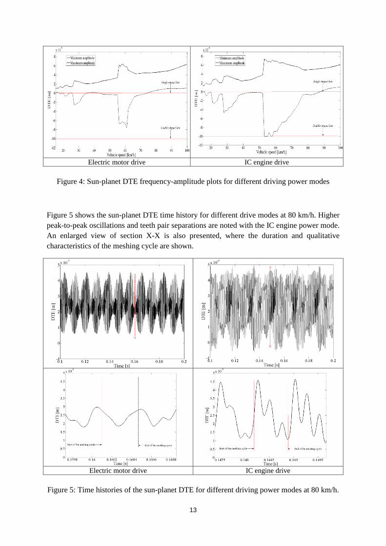
Figure 4: Sun-planet DTE frequency-amplitude plots for different driving power modes
Figure 5 shows the sun-planet DTE time history for different drive modes at 80 km/h. Higher peak-to-peak oscillations and teeth pair separations are noted with the IC engine power mode. An enlarged view of section X-X is also presented, where the duration and qualitative characteristics of the meshing cycle are shown.
Electric motor drive IC engine drive
Figure 5: Time histories of the sun-planet DTE for different driving power modes at 80 km/h.

14
For any root cause analysis during the design procedure, the effective frequencies observed in the DTE response are important. The FFT spectrum of the DTE for the IC engine mode is shown in figure 6. It reveals that the dominant contributions are at the meshing frequency (𝑓𝑚), the planet gear rotational frequency (𝑓𝑠), the ring gear rotational frequency (𝑓𝑟) and their modulations. A longer time history of the DTE is required in order to capture low frequency repetitive events, such as the periodic rotation of the planets and the ring gear. This also enables the effect of modulation with meshing frequency to be observed as shown in Figure 6. In these analyses the resisting torque on the wheels is calculated using equation (28) and a sufficient supplied input torque is assumed to maintain steady state equilibrium. Therefore, any fluctuations of the engine output torque (engine order vibration [26]) are ignored for this analysis. If these effects were to be included, then further deterioration in the NVH performance would be expected.
Figure 6: FFT spectrum of the sun-planet DTE for the IC engine driving mode at 80 km/h.
Figure 7 shows the lubricant film thickness variation for different power drive modes for the same time window of figure 5 (section X-X). A thicker film thickness in teeth pair meshing is noted for the EM drive mode. A sufficiently thick film thickness is noted to avoid the occurrence of mixed or boundary regimes of lubrication. In the IC engine mode, the predicted film thickness is in the range 1.2-2 μm, which indicates a mixed regime of lubrication and, thus a larger number of asperity interactions would be expected compared with the case of EM mode (as it is also confirmed by the results presented in figure 8).

15
Electric drive IC engine drive
Figure 7: Lubricant film thickness time histories during meshing of the sun-planet teeth pairs
for different driving power modes
The minimum lubricant film thickness values during the speed sweep simulation are presented in figure 8. Larger minimum film thickness values are noted for the EM power mode case.
Figure 8: Sun-planet meshing minimum lubricant film thickness values during the speed sweep with different drive power modes
Finally, a key result of interest in the tribological analysis is the planetary gear set transmission efficiency (as the result of frictional losses) (figure 9). Comparing different driving modes, the IC engine generally shows better efficiency. This is despite the higher lubricant film thickness in the EM mode. The reason for this is the maintenance of a higher contacting sliding velocity of teeth pairs through meshing with the EM drive mode. The result is a higher viscous shear of the lubricant, resulting in increased viscous friction. At higher speeds, the inefficiency of both systems is comparable.

16
Figure 9: Total inefficiency of the planetary gear system due to gear meshing during the speed sweep simulations in different drive modes
Conclusions:
A tribo-dynamic analysis of a planetary gear set for HEV applications is presented. A 6 DOF torsional model has been developed taking into account the non-Newtonian, thermal and mixed elastohydrodynamics in order to predict the conjunctional lubricant film thickness, friction and gear set efficiency. For the considered configurations, the results show that in the EM drive mode, teeth pair separations occur for shorter regions during the speed sweep, when compared with the IC engine drive mode. The EM power mode also shows smaller peak-peak values for the DTE. Therefore, operations in the EM drive mode show better NVH performance. However, the latter reveals worse transmission efficiency at lower vehicle speeds. The conclusions arrived at in the current study apply to the investigated drive configuration. Therefore, they should be considered as specific to the problem described. There are many hybrid drive configurations though. Thus, generic conclusions would require studies of further alternatives. This constitutes a future aim of the current research.
17
References:
[1] Won, S., Ashish, K., Sungwook, H. “6 speed automatic transmission vibration magnitude
prediction and whine noise improvement through transmission system modelling”, SAE
Technical paper 2011-01-153, 2011
[2] Kahraman, A. “Natural modes of planetary gear trains”, Journal of sound and Vibration,
1994, 173,125-130.
[3] Sun, T. and Hu, H.H. “Nonlinear dynamics of a planetary gear system with multiple
clearances”, Mechanism and Machine Theory, 2003, 38, 1371-1390.
[4] Eisele, G., Wolff, K., and Alt., N. “Application of vehicle interior noise simulation for
NVH analysis of a passenger car”, SAE Technical Paper 2005-01-2514, 2005
[5] Hwang, S.J., Stout, J.L. and Ling, C.C., “Modelling and analysis of powertrain torsional
response”, SAE Technical Paper 980276, 1998
[6] Syed, F. U., Kuang, M. L. and Ying, H. “Active damping wheel-torque control system to
reduce driveline oscillations in a power-split hybrid electric vehicle”, IEEE Trans. Veh.
Technol., 2009, 58, 4769-4785.
[7] Kahraman, A., Vijayakar, S., “Effect of Internal Gear Flexibility on the Quasi-Static
Behavior of a Planetary Gear Set”, Trans. ASME, Journal of Mechanical Design, 123, 2001,
408-415.
[8] Mohammadpour, M., Theodossiades, S. Rahnejat, H. “Transient mixed non-Newtonian
thermo-elastohydrodynamics of vehicle differential hypoid gears with starved partial counter-
flow inlet boundary”, Proc. IMechE, Part J: Journal of Engineering Tribology, 228(10), 2014,
1158-1173, doi: 10.1177/1350650114537805
[9] Velex, P., and Cahouet, V., "Experimental and numerical investigations on the influence
of tooth friction in spur and helical gear dynamics" Trans. ASME, J. Mech. Des., 2000, 122,
515-522.
[10] De la Cruz, M., Theodossiades, S. and Rahnejat, H. “An investigation of manual
transmission drive rattle”, Proc. IMechE, Part K: J. Multi-body Dynamics, 224(2), 2010, 167-
181
[11]- Koronias, G., Theodossiades, S., Rahnejat, H. and Saunders, T. “Axle whine
phenomenon in light trucks: a combined numerical and experimental investigation”, Proc.
IMechE, Part D: J. Automobile Engineering, 225(7), 2011, 885-894

18
[12] Dietl P., Wensing J. and Van Nijen G. C., “Rolling bearing damping for dynamic
analysis of multi-body systems-experimental and theoretical results”, Proc. IMechE, Part K:
Journal of Multi-body Dynamics, 214 (33), 2000, 33-43
[13] Mohammadpour, M., Theodossiades, S. and Rahnejat, H., “Multi-physics investigations on the dynamics of differential hypoid gears”, Trans. ASME, Journal of Vibration and Acoustics, 136(4), 2014, 041007.
[14] Mohammadpour, M., Theodossiades, S. and Rahnejat, H., “Tribodynamics of
differential hypoid gears”, International Gear Conference, 2014, Lyon, France.
[15] Mohammadpour, M., Theodossiades, S., Rahnejat, H. and Kelly, P., "Transmission
efficiency and noise, vibration and harshness refinement of differential hypoid gear pairs."
Proc. IMechE, Part K: J. Multi-body Dynamics, 228(1), 2014, 19-33
[16] Inalpolat, M. and Kahraman, A. “Dynamic modelling of planetary gears of automatic
transmissions”. Proc. IMechE, Part K: J. Multi-body Dynamics, 222(3), 2008, 229-242
[17] Ambarisha, V. K., Parker, R., “Suppression of Planet Mode Response in Planetary Gear
Dynamics Through Mesh Phasing”, Trans. ASME, Journal of Vibration and Acoustics, 128,
2006, 133-142.
[18] Greenwood, J. A. and Tripp, J. H., “The contact of two nominally flat rough surfaces”,
Proc. IMechE., J. Mech. Eng. Sci., 185, 1970-71, 625-633
[19] Gohar, R. and Rahnejat, H., “Fundamentals of Tribology”, Imperial College Press,
London, 2008
[20] Johnson, K. L., and R. Cameron. "Fourth Paper: Shear Behaviour of
Elastohydrodynamic Oil Films at High Rolling Contact Pressures." Proc. IMechE, J. Mech.
Eng. Sci., 182 (1), 1967, 307-330
[21] Mohammadpour, M., Theodossiades, S., Rahnejat, H. and Saunders, T., "Non-
Newtonian mixed elastohydrodynamics of differential hypoid gears at high loads."
Meccanica, 49(5), 2014, 1115-1138
[22] Evans, C. R. and Johnson, K. L. “Regimes of traction in elastohydrodynamic
lubrication”, Proc. IMechE, J. Mech. Eng. Sci., 200 (5), 1986, pp. 313–324
[23] Dowson, D. and Higginson, G.,R., “Elasto-hydrodynamic lubrication”, Pergamon Press, Oxford, 1977.
[24] Zhang, J., Tang, X., Yu, H., & Zou, L.. “Multi-body dynamics and noise analysis for the torsional vibration of a power-split hybrid driveline.” Proceedings of the Institution of Mechanical Engineers, Part K: Journal of Multi-body Dynamics, 2014, DOI: 1464419314540152.

19
[25] Karagiannis, I., Theodossiades, S. and Rahnejat, H., “On the dynamics of lubricated
hypoid gears”. Mechanism and Machine Theory, 2012, 48, 94-120.
[26] Rahnejat, H., “Multi-body Dynamics: Vehicles, Machines and Mechanisms”,
Professional Engineering Publishing, Bury St Edmunds, UK, 1998