Modbus Ethernet - OSIsoftcdn.osisoft.com/interfaces/1271/PI_ModbusE_3.1x.doc · Web viewMODBUS...
61
Modbus Ethernet Interface Documentation for NT Version 3.1x OSI Software, Inc.
Transcript of Modbus Ethernet - OSIsoftcdn.osisoft.com/interfaces/1271/PI_ModbusE_3.1x.doc · Web viewMODBUS...
Modbus Ethernet InterfaceDocumentation for NT
Version 3.1x
OSI Software, Inc.
How to Contact UsPhone (510) 297-5800 (main number)
(510) 297-5828 (technical support)Fax (510) 357-8136Internet [email protected]
World Wide Web
http://www.osisoft.com
Bulletin Board (510) 895-9423Telebit WorldBlazer modem (Hayes, MNP, or PEP compatible)8 data bits, 1 stop bit, no parity, up to 14400 BPS downloadprotocols: Xmodem, Ymodem, Zmodem, Kermit
Mail OSI Software, Inc.P.O. Box 727San Leandro, CA 94577-0427USA
OSI Software GmbH Hauptstrae 30 D-63674 Altenstadt 1Deutschland
OSI Software, LtdP. O. Box 8256Level One, 6-8 Nugent StreetAuckland 3, New Zealand
Unpublished -- rights reserved under the copyright laws of the United States.RESTRICTED RIGHTS LEGEND
Use, duplication, or disclosure by the Government is subject to restrictions as set forth in subparagraph (c)(1)(ii) of the Rights in Technical Data and Computer Software clause at DFARS 252.227-7013
Trademark statement—PI is a registered trademark of OSI Software, Inc. Microsoft Windows, Microsoft Windows for Workgroups, and Microsoft NT are registered trademarks of Microsoft Corporation. Solaris is a registered trademark of Sun Microsystems.
HP-UX is a registered trademark of Hewlett Packard Corp. IBM AIX RS/6000 is a registered trademark of the IBM Corporation. DUX, DEC VAX and DEC Alpha are registered trademarks of the Digital Equipment Corporation.
document.doc
1997 OSI Software, Inc. All rights reserved777 Davis Street, Suite 250, San Leandro, CA 94577

Table of ContentsINTRODUCTION.......................................................................................................................................... 1
OVERVIEW................................................................................................................................................... 2
PI POINT DEFINITION................................................................................................................................ 3
General Tag Configuration Information........................................................................................................ 3Input Tag Configuration............................................................................................................................. 10Output Tag Configuration.......................................................................................................................... 11Order of Data Pre/Post Processing..............................................................................................................13Additional Configuration for PI2................................................................................................................ 14
HARDWARE AND SOFTWARE................................................................................................................ 15
THE STARTUP COMMAND FILE............................................................................................................ 16
INTERFACE INSTALLATION.................................................................................................................. 20
Pre-Installation Notes:................................................................................................................................ 20Installation Procedure:................................................................................................................................ 20Post-Installation Tasks................................................................................................................................ 24
MODBUS INTERFACE SYSTEM ADMINISTRATION STARTING THE MODBUS INTERFACE....26
Automatic service startup....................................................................................................................... 26Manual service startup........................................................................................................................... 26Interactive startup.................................................................................................................................. 26
Stopping the MODBUS Interface...............................................................................................................26Registering the Modbus Interface as a Windows NT Service......................................................................27
Manual services..................................................................................................................................... 27Automatic services................................................................................................................................. 27
Removing the Modbus Interface as a Windows NT Service........................................................................27Status, Warning, And Error Messages........................................................................................................27
DATA ACCESS TABLE.............................................................................................................................. 28
APPENDIX A............................................................................................................................................... 30
Modbus Message Packets........................................................................................................................... 30Function codes 1-4: message packet sent to PLC...................................................................................30Function codes 1-4: message packet returned by PLC............................................................................30Function codes 5-6: message packet sent to PLC (except for data type 4)...............................................30Function codes 5-6: message packet sent to PLC (data type 4)...............................................................31Function codes 5-6: message packet returned by PLC............................................................................31Function code 16: message packet sent to PLC......................................................................................31Function code 16: message packet returned by PLC...............................................................................31
APPENDIX B................................................................................................................................................ 32
18-May-23 iii
Floating Point Representation..................................................................................................................... 32Floating Point, Data Type 4:.................................................................................................................. 33Floating Point, Data Type 5:................................................................................................................. 33Floating Point Type 6:........................................................................................................................... 33Data type 7, Binary data, 4-byte integer, Support of floating points represented as 4-byte integers........33Data type 8, Siemens Floating-Point Representation..............................................................................34Function code 65................................................................................................................................... 34
APPENDIX C............................................................................................................................................... 35
Currently Supported PLC’s......................................................................................................................... 35
APPENDIX D............................................................................................................................................... 36
Trouble shooting – Using Modbus Simulators............................................................................................36Troubleshooting – Error Messages.............................................................................................................. 36
APPENDIX E................................................................................................................................................ 37
Differences between Versions 2.x and 3.x of the Modbus Interface............................................................37
iv OSI Software, Inc.
IntroductionThis interface does not support Modbus serial-based communication or Modbus Plus communication. The versioning for this interface began at version 3.0. The previous interface, version 2.x, does support Modbus serial based communication and Modbus Plus Communication. Version 3.x only supports Modbus Ethernet.
This manual is a description of the Modbus Ethernet Interface to the PI System for Windows NT. The interface can be run either on a PI 3 server node or on an API node that communicates to either a PI 2 or PI 3 server. Only Modbus communication across an Ethernet network is supported. The currently supported PLC’s are listed in Appendix C.
The interface serves as a Master in a Master-Slave relationship. There is a maximum limitation of ninety-nine (99) concurrent implementations of the interface. Operating system performance may be effected when running multiple copies of the interface on a single PC.
The interface is designed to read data from a PLC on a periodic or event basis and to send output data (commands to the PLC) on an event basis. The Modbus Interface attempts to optimize scanning performance by grouping input tags with the same scan rate, PLC destination node, and function code.
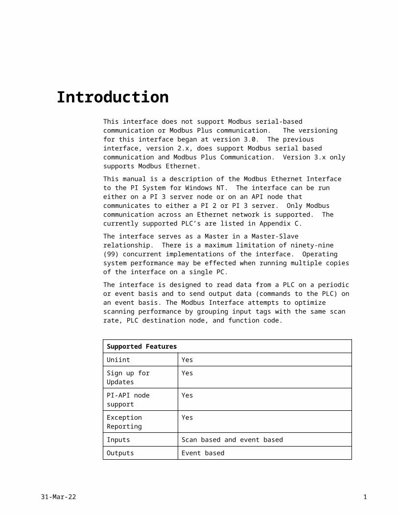
Supported Features
Uniint Yes
Sign up for Updates Yes
PI-API node support Yes
Exception Reporting Yes
Inputs Scan based and event based
Outputs Event based
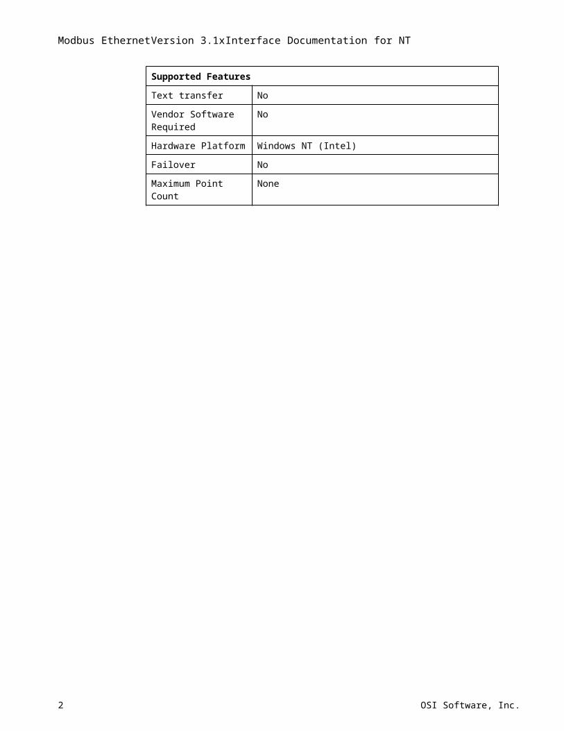
Text transfer No
Vendor Software Required No
Hardware Platform Windows NT (Intel)
Failover No
Maximum Point Count None
18-May-23 1
Modbus EthernetVersion 3.1xInterface Documentation for NT
OverviewFor proper interface operation, the user must configure input points (input tags) and/or output points (output tags) on a PI2 or PI3 server. Input tags are used to receive data from PLC nodes. Data are received either at a given frequency or after a value is sent to a “trigger” tag. Output tags are used to send commands to a PLC. A command is sent to a PLC after a value is sent to a “source” tag or after a value is sent to the output tag itself, depending on the configuration of the output tag. All values that are written to the snapshot or archive use the system time from the PI home node. If a communication error occurs while attempting to read data from a PLC, the interface will attempt to re-establish communication until it is successful.
At startup, the interface scans the PI Point Database for all associated points and builds its own point list. During runtime, the interface continues to check the PI Point Database for point updates and modifies its point list accordingly. If the Scan field of any point on the point list is set to zero, the point is removed from the point list. The point is added once again after the Scan field is turned back on. If neither a fixed scan rate nor a valid trigger tag are found for a given point, the point will not be added to the list.
The interface checks whether coil addresses and register addresses are within a default range. At the user’s discretion, these ranges can be adjusted in an optional Data Access Table. See the section called “Data Access Table” for more information.
The interface is designed to optimize data transfer and minimize communication traffic by collecting input data into groups. Inputs points that are configured with the same function code, scan rate, and PLC destination node are grouped together. When the amount of data that is requested for a given group exceeds the maximum data transfer size (100 byte maximum for inputs or coils, 200 byte maximum for registers) a new group is begun. The proper use of PLC memory can greatly enhance the efficiency and overall data throughput of the interface.
2 OSI Software, Inc.
PI Point DefinitionGeneral Tag Configuration Information
PI points must be configured in order to transmit data to or from a PLC. The points can be configured on either a PI2 or PI3 home node.
The required PI point attributes and a few optional PI point attributes are described below for the Modbus interface. Additional information on point attributes can be found in the Data Archive (DA) section of the PI System Manual (for PI2 home nodes) or the PI Data Archive Manual for Windows NT and UNIX (for PI3 home nodes).
Point configuration is the same on PI 2 and PI 3 home nodes, except where indicated below. Note that there are several PI Point attributes that are listed as being required; yet, these attributes have a default value associated with them. In this case, “required” means that the value of the PI Point attribute will typically need to be changed from the default value in order for its configuration to be correct.
In the following, the PI Point attributes are in bold-faced type, followed by a description of the attribute.
TagRequired, no default. The Tag is the name of the PI Point.
PointSourceRequired, default: L. A PointSource is a single character that is used to identify the PI point as a point that belongs to the Modbus interface. The PointSource is typically assigned a value of M for the Modbus interface. The PointSource attribute corresponds to the /ps argument in the Startup Command file. For a PI 2 Home node, one must add the PointSource character to the PI 2 Point Source Table. See “Additional Configuration for PI 2” below.
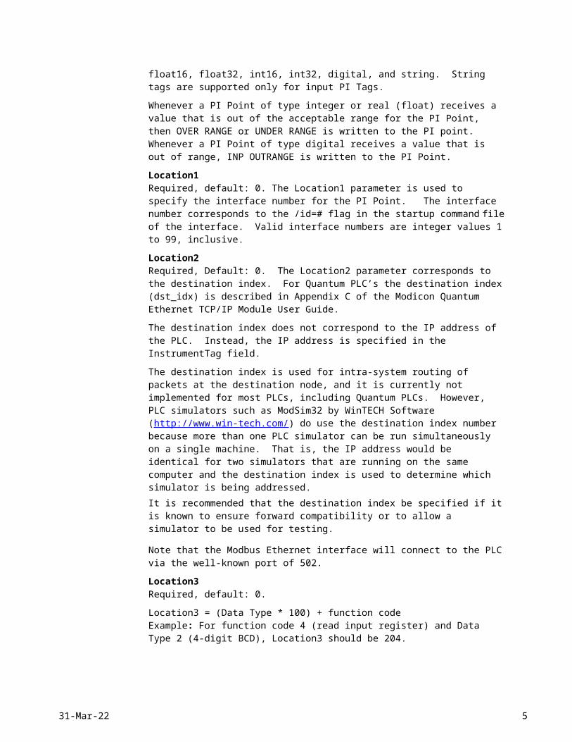
PointTypeOptional, PI 2 default: scaled real, PI 3 default: float32. For a PI 2 home node, the interface supports all point types (scaled real, full precision real, integer, and digital). For a PI 3 home node the following point types are supported: float16, float32, int16, int32, digital, and string. String tags are supported only for input PI Tags.
Whenever a PI Point of type integer or real (float) receives a value that is out of the acceptable range for the PI Point, then OVER RANGE or UNDER RANGE is written to the PI point. Whenever a PI Point of type digital receives a value that is out of range, INP OUTRANGE is written to the PI Point.
Location1Required, default: 0. The Location1 parameter is used to specify the interface number for the PI Point. The interface number corresponds to the /id=# flag in the startup command file of the interface. Valid interface numbers are integer values 1 to 99, inclusive.
Location2Required, Default: 0. The Location2 parameter corresponds to the destination index. For Quantum PLC’s the destination index (dst_idx) is described in Appendix C of the Modicon Quantum Ethernet TCP/IP Module User Guide.
18-May-23 3
Modbus EthernetVersion 3.1xInterface Documentation for NT
The destination index does not correspond to the IP address of the PLC. Instead, the IP address is specified in the InstrumentTag field.
The destination index is used for intra-system routing of packets at the destination node, and it is currently not implemented for most PLCs, including Quantum PLCs. However, PLC simulators such as ModSim32 by WinTECH Software (http://www.win-tech.com/) do use the destination index number because more than one PLC simulator can be run simultaneously on a single machine. That is, the IP address would be identical for two simulators that are running on the same computer and the destination index is used to determine which simulator is being addressed. It is recommended that the destination index be specified if it is known to ensure forward compatibility or to allow a simulator to be used for testing.
Note that the Modbus Ethernet interface will connect to the PLC via the well-known port of 502.
Location3Required, default: 0.
Location3 = (Data Type * 100) + function codeExample: For function code 4 (read input register) and Data Type 2 (4-digit BCD), Location3 should be 204.
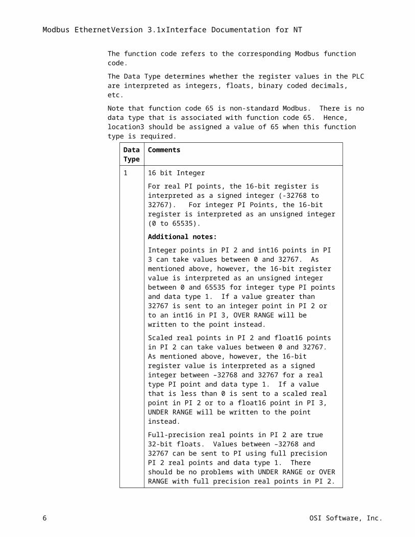
The function code refers to the corresponding Modbus function code.
The Data Type determines whether the register values in the PLC are interpreted as integers, floats, binary coded decimals, etc.
Note that function code 65 is non-standard Modbus. There is no data type that is associated with function code 65. Hence, location3 should be assigned a value of 65 when this function type is required.
Data Type
Comments
1 16 bit Integer
For real PI points, the 16-bit register is interpreted as a signed integer (-32768 to 32767). For integer PI Points, the 16-bit register is interpreted as an unsigned integer (0 to 65535).
Additional notes:
Integer points in PI 2 and int16 points in PI 3 can take values between 0 and 32767. As mentioned above, however, the 16-bit register value is interpreted as an unsigned integer between 0 and 65535 for integer type PI points and data type 1. If a value greater than 32767 is sent to an integer point in PI 2 or to an int16 in PI 3, OVER RANGE will be written to the point instead.
Scaled real points in PI 2 and float16 points in PI 2 can take values between 0 and 32767. As mentioned above, however, the 16-bit register value is interpreted as a signed integer between –32768 and 32767 for a real type PI point and data type 1. If a value that is less than 0 is sent to a scaled real point in PI 2 or to a float16 point in PI 3, UNDER RANGE will be written to the point instead.
Full-precision real points in PI 2 are true 32-bit floats. Values between –32768 and 32767 can be sent to PI using full precision PI 2 real points and data type 1. There should be no problems with UNDER RANGE or OVER RANGE with full precision real points in PI 2.
The 16-bit register value for data type 1 is interpreted as an unsigned integer
4 OSI Software, Inc.
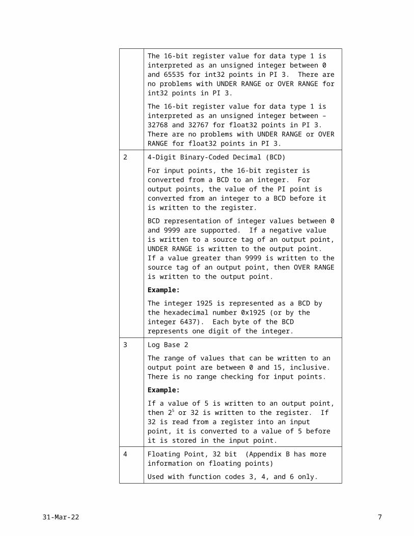
between 0 and 65535 for int32 points in PI 3. There are no problems with UNDER RANGE or OVER RANGE for int32 points in PI 3.
The 16-bit register value for data type 1 is interpreted as an unsigned integer between –32768 and 32767 for float32 points in PI 3. There are no problems with UNDER RANGE or OVER RANGE for float32 points in PI 3.
2 4-Digit Binary-Coded Decimal (BCD)
For input points, the 16-bit register is converted from a BCD to an integer. For output points, the value of the PI point is converted from an integer to a BCD before it is written to the register.
BCD representation of integer values between 0 and 9999 are supported. If a negative value is written to a source tag of an output point, UNDER RANGE is written to the output point. If a value greater than 9999 is written to the source tag of an output point, then OVER RANGE is written to the output point.
Example:
The integer 1925 is represented as a BCD by the hexadecimal number 0x1925 (or by the integer 6437). Each byte of the BCD represents one digit of the integer.
3 Log Base 2
The range of values that can be written to an output point are between 0 and 15, inclusive. There is no range checking for input points.
Example:
If a value of 5 is written to an output point, then 25 or 32 is written to the register. If 32 is read from a register into an input point, it is converted to a value of 5 before it is stored in the input point.
4 Floating Point, 32 bit (Appendix B has more information on floating points)
Used with function codes 3, 4, and 6 only.
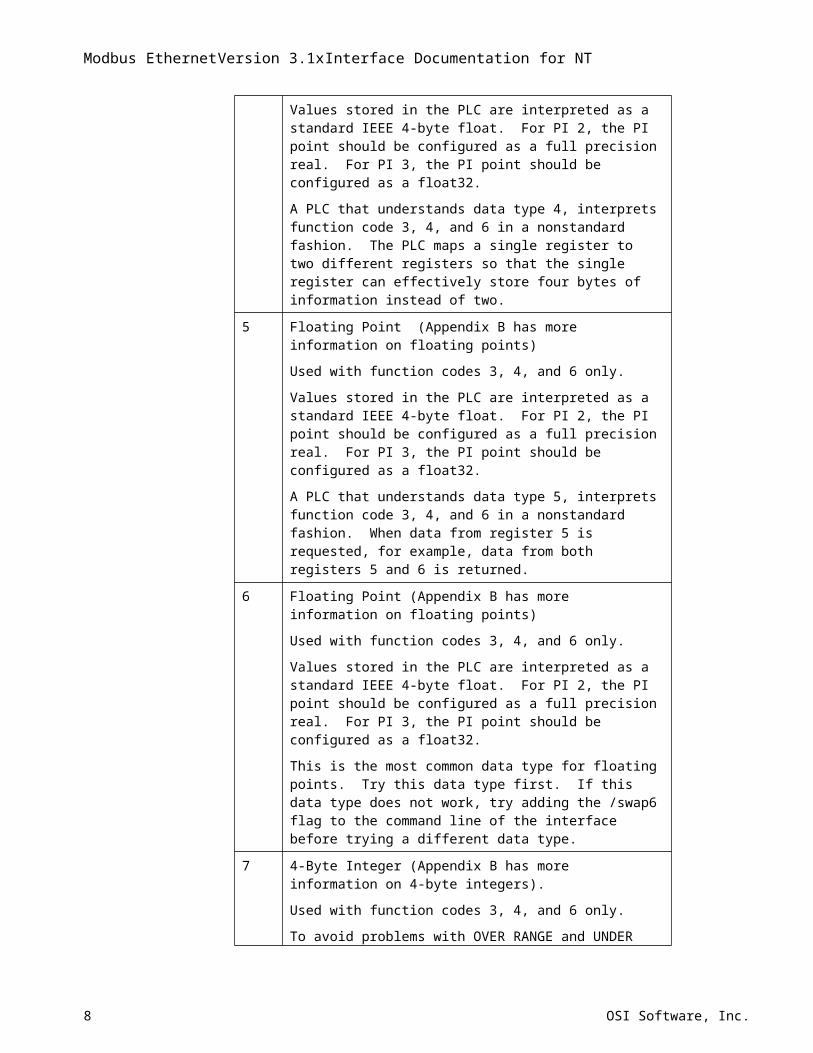
Values stored in the PLC are interpreted as a standard IEEE 4-byte float. For PI 2, the PI point should be configured as a full precision real. For PI 3, the PI point should be configured as a float32.
A PLC that understands data type 4, interprets function code 3, 4, and 6 in a nonstandard fashion. The PLC maps a single register to two different registers so that the single register can effectively store four bytes of information instead of two.
5 Floating Point (Appendix B has more information on floating points)
Used with function codes 3, 4, and 6 only.
Values stored in the PLC are interpreted as a standard IEEE 4-byte float. For PI 2, the PI point should be configured as a full precision real. For PI 3, the PI point should be configured as a float32.
A PLC that understands data type 5, interprets function code 3, 4, and 6 in a nonstandard fashion. When data from register 5 is requested, for example, data from both registers 5 and 6 is returned.
6 Floating Point (Appendix B has more information on floating points)
Used with function codes 3, 4, and 6 only.
Values stored in the PLC are interpreted as a standard IEEE 4-byte float. For PI 2, the PI point should be configured as a full precision real. For PI 3,
18-May-23 5
Modbus EthernetVersion 3.1xInterface Documentation for NT
the PI point should be configured as a float32.
This is the most common data type for floating points. Try this data type first. If this data type does not work, try adding the /swap6 flag to the command line of the interface before trying a different data type.
7 4-Byte Integer (Appendix B has more information on 4-byte integers).
Used with function codes 3, 4, and 6 only.
To avoid problems with OVER RANGE and UNDER RANGE, the PI Point should be configured as a full precision real in PI 2 or as an int32 or a float32 in PI 3. See data type 1 for further information regarding the limitations of the different PI Point types.
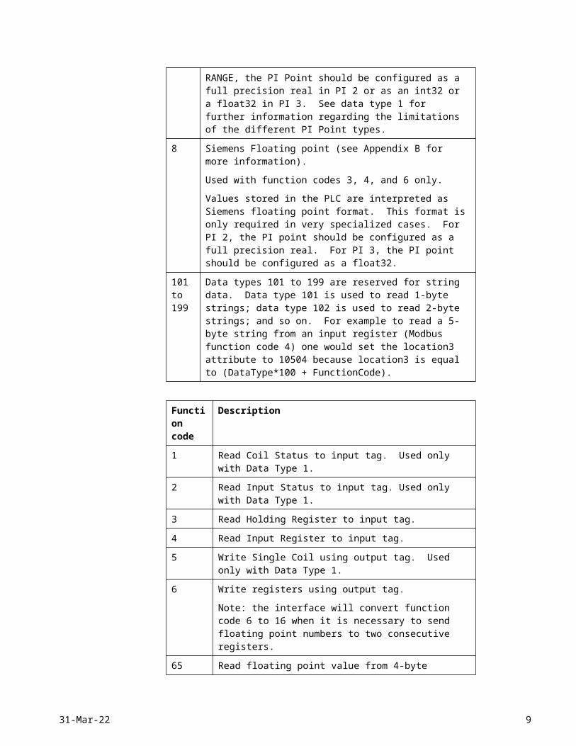
8 Siemens Floating point (see Appendix B for more information).
Used with function codes 3, 4, and 6 only.
Values stored in the PLC are interpreted as Siemens floating point format. This format is only required in very specialized cases. For PI 2, the PI point should be configured as a full precision real. For PI 3, the PI point should be configured as a float32.
101 to 199
Data types 101 to 199 are reserved for string data. Data type 101 is used to read 1-byte strings; data type 102 is used to read 2-byte strings; and so on. For example to read a 5-byte string from an input register (Modbus function code 4) one would set the location3 attribute to 10504 because location3 is equal to (DataType*100 + FunctionCode).
Function code
Description
1 Read Coil Status to input tag. Used only with Data Type 1.
2 Read Input Status to input tag. Used only with Data Type 1.
3 Read Holding Register to input tag.
4 Read Input Register to input tag.
5 Write Single Coil using output tag. Used only with Data Type 1.
6 Write registers using output tag.
Note: the interface will convert function code 6 to 16 when it is necessary to send floating point numbers to two consecutive registers.
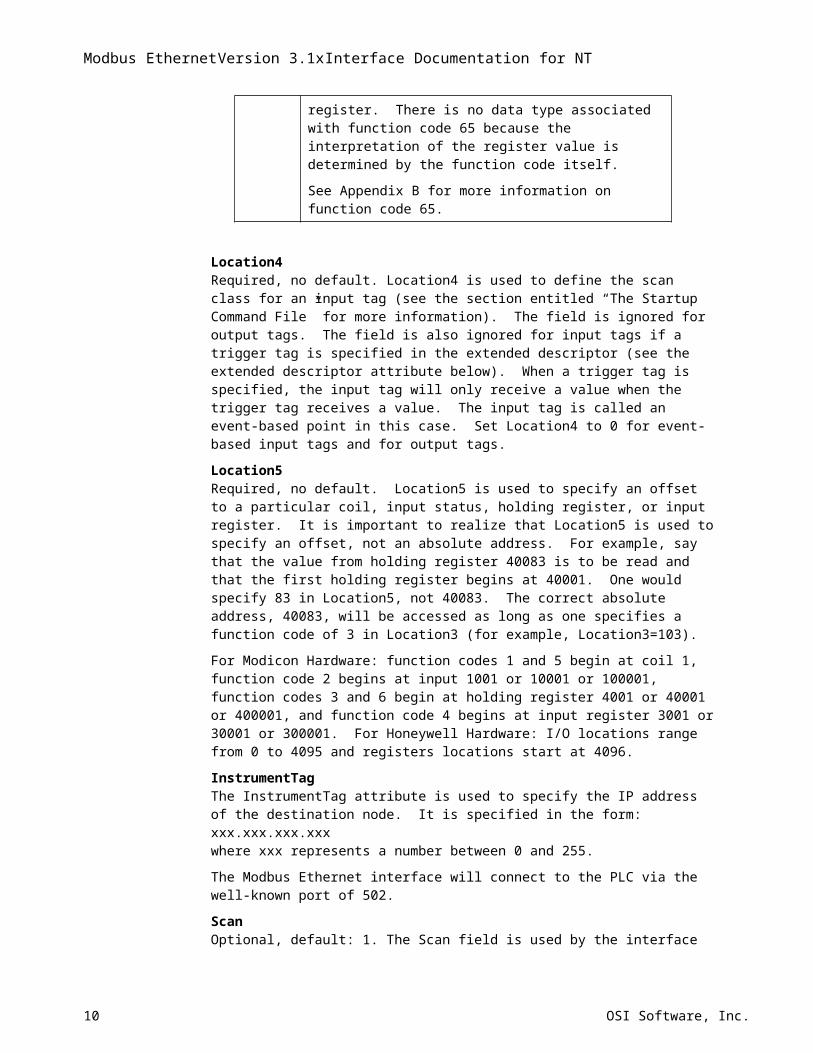
65 Read floating point value from 4-byte register. There is no data type associated with function code 65 because the interpretation of the register value is determined by the function code itself.
See Appendix B for more information on function code 65.
Location4Required, no default. Location4 is used to define the scan class for an input tag (see the section entitled “The Startup Command File” for more information). The field is ignored for output tags. The field is also ignored for input tags if a trigger tag is specified in the extended descriptor (see the extended descriptor attribute below). When a trigger tag is specified, the input tag will only receive a value when the trigger tag receives a value. The input tag is called an event-based point in this case. Set Location4 to 0 for event-based input tags and for output tags.
6 OSI Software, Inc.
Location5Required, no default. Location5 is used to specify an offset to a particular coil, input status, holding register, or input register. It is important to realize that Location5 is used to specify an offset, not an absolute address. For example, say that the value from holding register 40083 is to be read and that the first holding register begins at 40001. One would specify 83 in Location5, not 40083. The correct absolute address, 40083, will be accessed as long as one specifies a function code of 3 in Location3 (for example, Location3=103).
For Modicon Hardware: function codes 1 and 5 begin at coil 1, function code 2 begins at input 1001 or 10001 or 100001, function codes 3 and 6 begin at holding register 4001 or 40001 or 400001, and function code 4 begins at input register 3001 or 30001 or 300001. For Honeywell Hardware: I/O locations range from 0 to 4095 and registers locations start at 4096.
InstrumentTagThe InstrumentTag attribute is used to specify the IP address of the destination node. It is specified in the form:xxx.xxx.xxx.xxxwhere xxx represents a number between 0 and 255.
The Modbus Ethernet interface will connect to the PLC via the well-known port of 502.
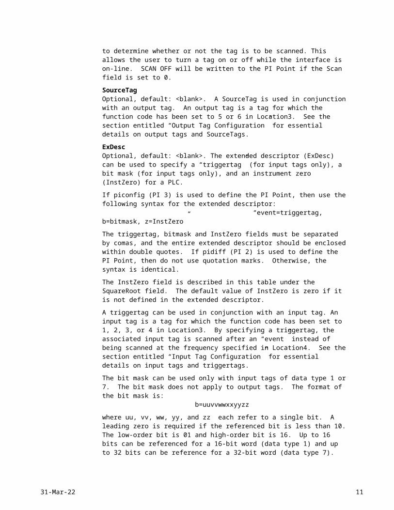
ScanOptional, default: 1. The Scan field is used by the interface to determine whether or not the tag is to be scanned. This allows the user to turn a tag on or off while the interface is on-line. SCAN OFF will be written to the PI Point if the Scan field is set to 0.
SourceTagOptional, default: <blank>. A SourceTag is used in conjunction with an output tag. An output tag is a tag for which the function code has been set to 5 or 6 in Location3. See the section entitled “Output Tag Configuration” for essential details on output tags and SourceTags.
ExDescOptional, default: <blank>. The extended descriptor (ExDesc) can be used to specify a “triggertag” (for input tags only), a bit mask (for input tags only), and an instrument zero (InstZero) for a PLC.
If piconfig (PI 3) is used to define the PI Point, then use the following syntax for the extended descriptor: “event=triggertag, b=bitmask, z=InstZero”
The triggertag, bitmask and InstZero fields must be separated by comas, and the entire extended descriptor should be enclosed within double quotes. If pidiff (PI 2) is used to define the PI Point, then do not use quotation marks. Otherwise, the syntax is identical.
The InstZero field is described in this table under the SquareRoot field. The default value of InstZero is zero if it is not defined in the extended descriptor.
A triggertag can be used in conjunction with an input tag. An input tag is a tag for which the function code has been set to 1, 2, 3, or 4 in Location3. By specifying a triggertag, the associated input tag is scanned after an “event” instead of being scanned at the frequency specified in Location4. See the section entitled “Input Tag Configuration” for essential details on input tags and triggertags.
The bit mask can be used only with input tags of data type 1 or 7. The bit mask does not apply to output tags. The format of the bit mask is: b=uuvvwwxxyyzz
where uu, vv, ww, yy, and zz each refer to a single bit. A leading zero is required if the referenced bit is less than 10. The low-order bit is 01 and high-order bit is 16. Up to 16 bits
18-May-23 7
Modbus EthernetVersion 3.1xInterface Documentation for NT
can be referenced for a 16-bit word (data type 1) and up to 32 bits can be reference for a 32-bit word (data type 7).
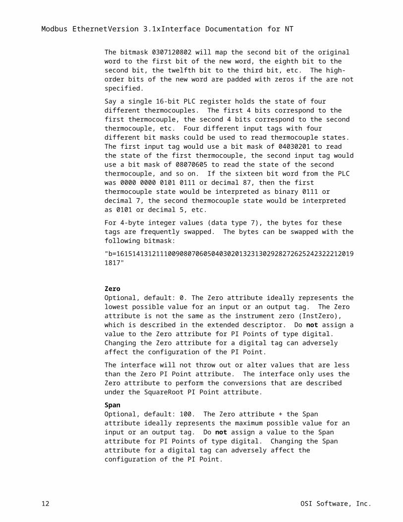
The bitmask 0307120802 will map the second bit of the original word to the first bit of the new word, the eighth bit to the second bit, the twelfth bit to the third bit, etc. The high-order bits of the new word are padded with zeros if the are not specified.
Say a single 16-bit PLC register holds the state of four different thermocouples. The first 4 bits correspond to the first thermocouple, the second 4 bits correspond to the second thermocouple, etc. Four different input tags with four different bit masks could be used to read thermocouple states. The first input tag would use a bit mask of 04030201 to read the state of the first thermocouple, the second input tag would use a bit mask of 08070605 to read the state of the second thermocouple, and so on. If the sixteen bit word from the PLC was 0000 0000 0101 0111 or decimal 87, then the first thermocouple state would be interpreted as binary 0111 or decimal 7, the second thermocouple state would be interpreted as 0101 or decimal 5, etc.
For 4-byte integer values (data type 7), the bytes for these tags are frequently swapped. The bytes can be swapped with the following bitmask:
"b=1615141312111009080706050403020132313029282726252423222120191817"
ZeroOptional, default: 0. The Zero attribute ideally represents the lowest possible value for an input or an output tag. The Zero attribute is not the same as the instrument zero (InstZero), which is described in the extended descriptor. Do not assign a value to the Zero attribute for PI Points of type digital. Changing the Zero attribute for a digital tag can adversely affect the configuration of the PI Point.
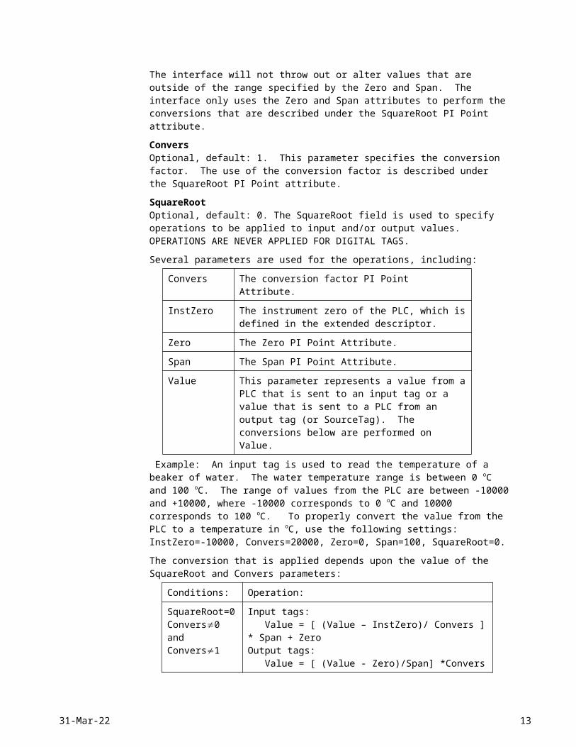
The interface will not throw out or alter values that are less than the Zero PI Point attribute. The interface only uses the Zero attribute to perform the conversions that are described under the SquareRoot PI Point attribute.
SpanOptional, default: 100. The Zero attribute + the Span attribute ideally represents the maximum possible value for an input or an output tag. Do not assign a value to the Span attribute for PI Points of type digital. Changing the Span attribute for a digital tag can adversely affect the configuration of the PI Point.
The interface will not throw out or alter values that are outside of the range specified by the Zero and Span. The interface only uses the Zero and Span attributes to perform the conversions that are described under the SquareRoot PI Point attribute.
ConversOptional, default: 1. This parameter specifies the conversion factor. The use of the conversion factor is described under the SquareRoot PI Point attribute.
SquareRootOptional, default: 0. The SquareRoot field is used to specify operations to be applied to input and/or output values. OPERATIONS ARE NEVER APPLIED FOR DIGITAL TAGS.
Several parameters are used for the operations, including:
Convers The conversion factor PI Point Attribute.
InstZero The instrument zero of the PLC, which is defined in the extended descriptor.
Zero The Zero PI Point Attribute.
Span The Span PI Point Attribute.
8 OSI Software, Inc.
Value This parameter represents a value from a PLC that is sent to an input tag or a value that is sent to a PLC from an output tag (or SourceTag). The conversions below are performed on Value.
Example: An input tag is used to read the temperature of a beaker of water. The water temperature range is between 0 oC and 100 oC. The range of values from the PLC are between -10000 and +10000, where -10000 corresponds to 0 oC and 10000 corresponds to 100 oC. To properly convert the value from the PLC to a temperature in oC, use the following settings: InstZero=-10000, Convers=20000, Zero=0, Span=100, SquareRoot=0.
The conversion that is applied depends upon the value of the SquareRoot and Convers parameters:
Conditions: Operation:
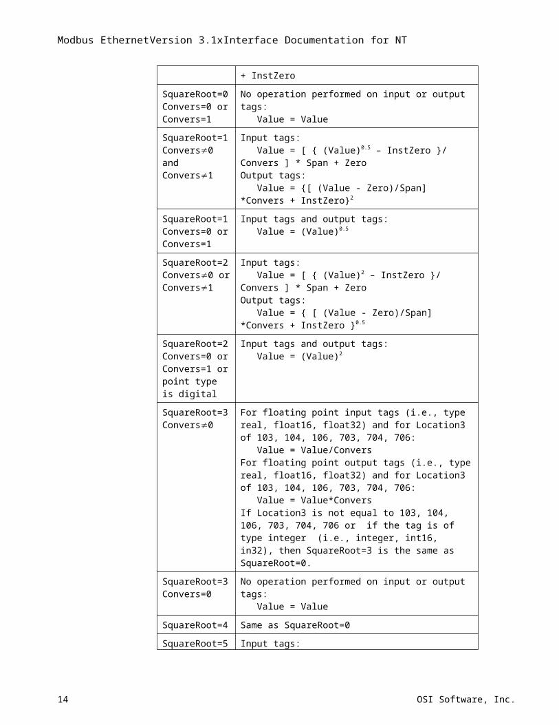
SquareRoot=0Convers0 andConvers1
Input tags: Value = [ (Value – InstZero)/ Convers ] * Span + ZeroOutput tags: Value = [ (Value - Zero)/Span] *Convers + InstZero
SquareRoot=0Convers=0 orConvers=1
No operation performed on input or output tags: Value = Value
SquareRoot=1Convers0 andConvers1
Input tags: Value = [ { (Value)0.5 – InstZero }/ Convers ] * Span + ZeroOutput tags: Value = {[ (Value - Zero)/Span] *Convers + InstZero}2
SquareRoot=1Convers=0 orConvers=1
Input tags and output tags: Value = (Value)0.5
SquareRoot=2Convers0 orConvers1
Input tags: Value = [ { (Value)2 – InstZero }/ Convers ] * Span + ZeroOutput tags: Value = { [ (Value - Zero)/Span] *Convers + InstZero }0.5
SquareRoot=2Convers=0 orConvers=1 or point type is digital
Input tags and output tags: Value = (Value)2
SquareRoot=3Convers0
For floating point input tags (i.e., type real, float16, float32) and for Location3 of 103, 104, 106, 703, 704, 706: Value = Value/ConversFor floating point output tags (i.e., type real, float16, float32) and for Location3 of 103, 104, 106, 703, 704, 706: Value = Value*ConversIf Location3 is not equal to 103, 104, 106, 703, 704, 706 or if the tag is of type integer (i.e., integer, int16, in32), then SquareRoot=3 is the same as SquareRoot=0.
SquareRoot=3Convers=0
No operation performed on input or output tags: Value = Value
SquareRoot=4 Same as SquareRoot=0
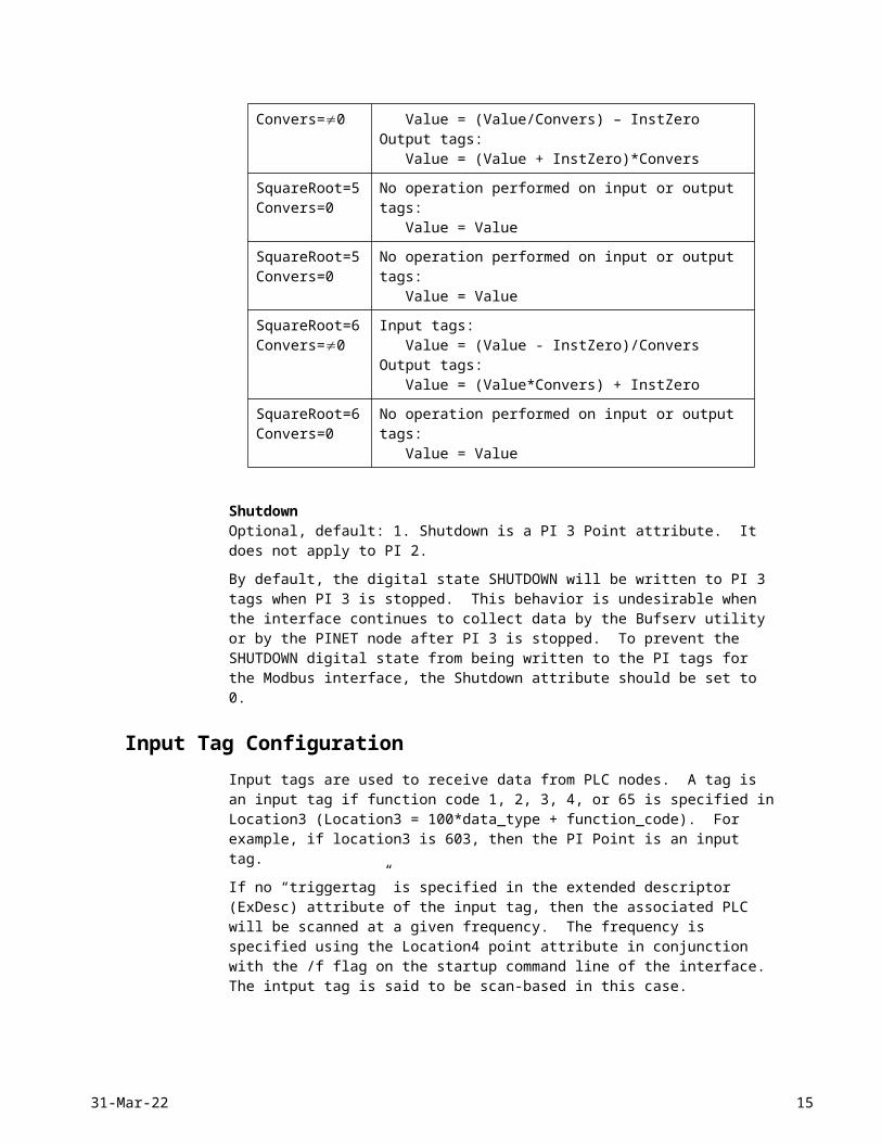
SquareRoot=5Convers=0
Input tags: Value = (Value/Convers) – InstZeroOutput tags:
18-May-23 9
Modbus EthernetVersion 3.1xInterface Documentation for NT
Value = (Value + InstZero)*Convers
SquareRoot=5Convers=0
No operation performed on input or output tags: Value = Value
SquareRoot=5Convers=0
No operation performed on input or output tags: Value = Value
SquareRoot=6Convers=0
Input tags: Value = (Value - InstZero)/ConversOutput tags: Value = (Value*Convers) + InstZero
SquareRoot=6Convers=0
No operation performed on input or output tags: Value = Value
ShutdownOptional, default: 1. Shutdown is a PI 3 Point attribute. It does not apply to PI 2.
By default, the digital state SHUTDOWN will be written to PI 3 tags when PI 3 is stopped. This behavior is undesirable when the interface continues to collect data by the Bufserv utility or by the PINET node after PI 3 is stopped. To prevent the SHUTDOWN digital state from being written to the PI tags for the Modbus interface, the Shutdown attribute should be set to 0.
Input Tag ConfigurationInput tags are used to receive data from PLC nodes. A tag is an input tag if function code 1, 2, 3, 4, or 65 is specified in Location3 (Location3 = 100*data_type + function_code). For example, if location3 is 603, then the PI Point is an input tag.
If no “triggertag” is specified in the extended descriptor (ExDesc) attribute of the input tag, then the associated PLC will be scanned at a given frequency. The frequency is specified using the Location4 point attribute in conjunction with the /f flag on the startup command line of the interface. The intput tag is said to be scan-based in this case.
If a “triggertag” is specified in the extended descriptor (ExDesc) attribute of the input tag, then the associated PLC will be scanned only when a new value is sent to the snapshot of the triggertag. The input tag is said to be event-based in this case.
Whenever a complete response fails to be received from a PLC before a configurable timeout period has expired (see the /to=x startup command-line parameter), IO TIMEOUT will be written to the affected tags.
If a communication error occurs that is not associated with a timeout, then BAD INPUT will be written to the affected tags instead of IO TIMEOUT.
If the Scan field of an input tag is turned off while the interface is running, SCAN OFF (digital state 238) will be written to the input tag.
There are several other digital states that can also be written to input tags. These must be handled on a case-by-case basis.
Output Tag ConfigurationOutput tags are used to send commands to a PLC node. A tag is an output tag if function code 5 or 6 is specified in Location3. Commands are sent to the PLC only upon an event. An event is triggered in one of two ways, depending upon the configuration of the output tag.
10 OSI Software, Inc.
Configuration 1 (recommended): In this configuration, a command is written to the PLC when an event is detected for a SourceTag. A SouceTag is associated with an output tag through the output tag’s SourceTag field. The value of the SourceTag is written to the output tag if the command is successful. The PointType of the output tag and SourceTag do not need to be the same.
Configuration 2: In this configuration, a command is written to the PLC when an event is detected for the output tag itself. This configuration is enabled if no SourceTag is defined in the output tag’s SourceTag field.
When do “events” occur? An event occurs whenever a value reaches the snapshot of the SourceTag (configuration 1) or the output tag (configuration 2). The actual value of the snapshot does not need to change to trigger an event
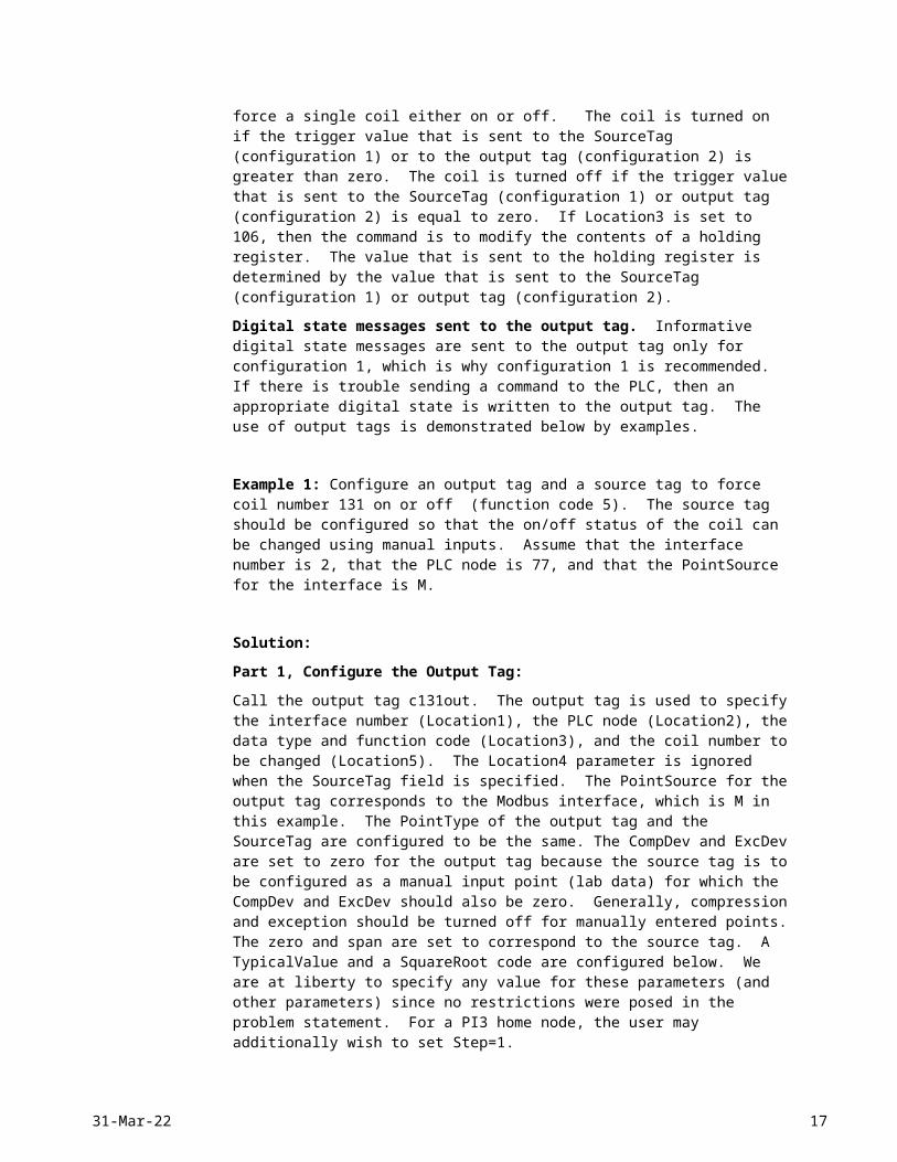
What commands are sent to the PLC? The command is determined by the Location3 value of the output tag. For example, if Location3 is set to 105, then the command to the PLC will be to force a single coil either on or off. The coil is turned on if the trigger value that is sent to the SourceTag (configuration 1) or to the output tag (configuration 2) is greater than zero. The coil is turned off if the trigger value that is sent to the SourceTag (configuration 1) or output tag (configuration 2) is equal to zero. If Location3 is set to 106, then the command is to modify the contents of a holding register. The value that is sent to the holding register is determined by the value that is sent to the SourceTag (configuration 1) or output tag (configuration 2).
Digital state messages sent to the output tag. Informative digital state messages are sent to the output tag only for configuration 1, which is why configuration 1 is recommended. If there is trouble sending a command to the PLC, then an appropriate digital state is written to the output tag. The use of output tags is demonstrated below by examples.
Example 1: Configure an output tag and a source tag to force coil number 131 on or off (function code 5). The source tag should be configured so that the on/off status of the coil can be changed using manual inputs. Assume that the interface number is 2, that the PLC node is 77, and that the PointSource for the interface is M.
Solution:
Part 1, Configure the Output Tag:
Call the output tag c131out. The output tag is used to specify the interface number (Location1), the PLC node (Location2), the data type and function code (Location3), and the coil number to be changed (Location5). The Location4 parameter is ignored when the SourceTag field is specified. The PointSource for the output tag corresponds to the Modbus interface, which is M in this example. The PointType of the output tag and the SourceTag are configured to be the same. The CompDev and ExcDev are set to zero for the output tag because the source tag is to be configured as a manual input point (lab data) for which the CompDev and ExcDev should also be zero. Generally, compression and exception should be turned off for manually entered points. The zero and span are set to correspond to the source tag. A TypicalValue and a SquareRoot code are configured below. We are at liberty to specify any value for these parameters (and other parameters) since no restrictions were posed in the problem statement. For a PI3 home node, the user may additionally wish to set Step=1.
Output Tag Configuration - Example 1
PI2 Home node PI3 Home node
18-May-23 11
Modbus EthernetVersion 3.1xInterface Documentation for NT
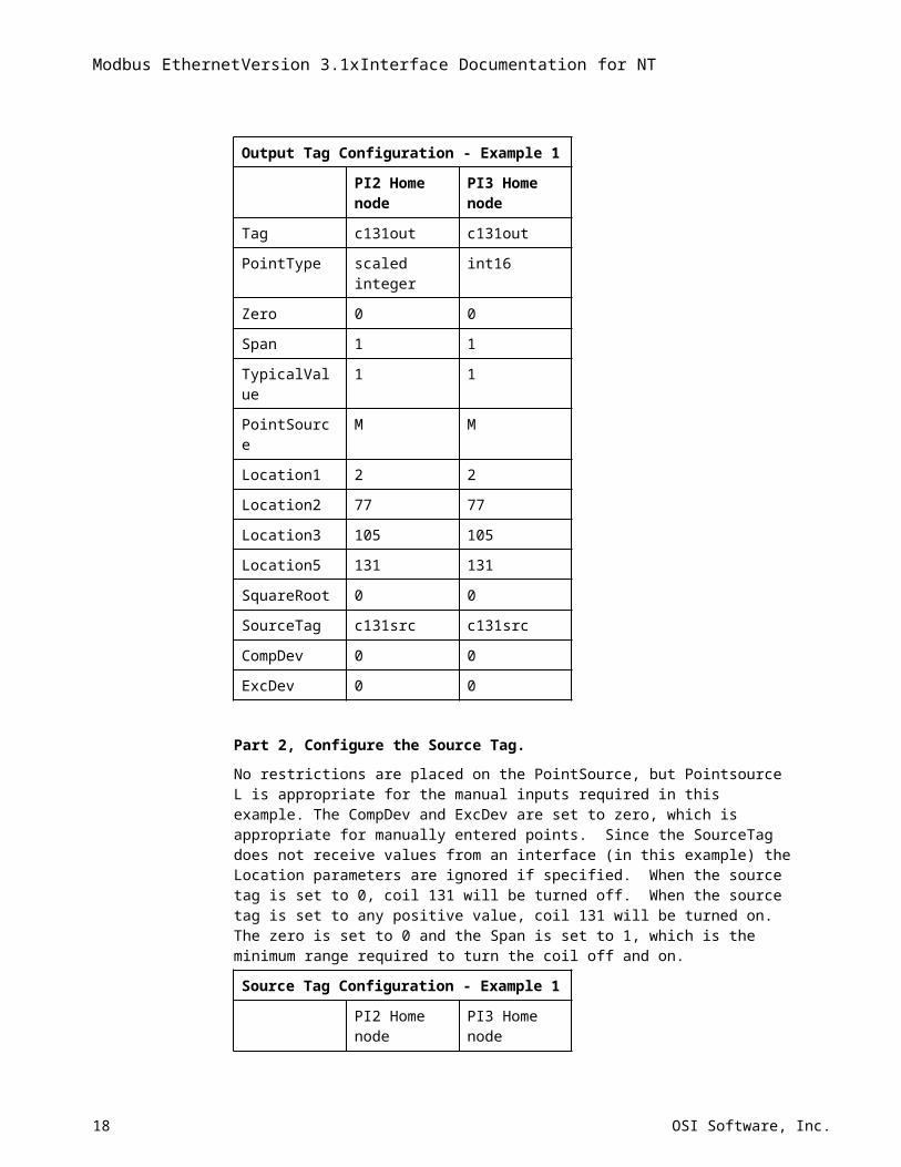
Output Tag Configuration - Example 1
Tag c131out c131out
PointType scaled integer int16
Zero 0 0
Span 1 1
TypicalValue 1 1
PointSource M M
Location1 2 2
Location2 77 77
Location3 105 105
Location5 131 131
SquareRoot 0 0
SourceTag c131src c131src
CompDev 0 0
ExcDev 0 0
Part 2, Configure the Source Tag.
No restrictions are placed on the PointSource, but Pointsource L is appropriate for the manual inputs required in this example. The CompDev and ExcDev are set to zero, which is appropriate for manually entered points. Since the SourceTag does not receive values from an interface (in this example) the Location parameters are ignored if specified. When the source tag is set to 0, coil 131 will be turned off. When the source tag is set to any positive value, coil 131 will be turned on. The zero is set to 0 and the Span is set to 1, which is the minimum range required to turn the coil off and on.
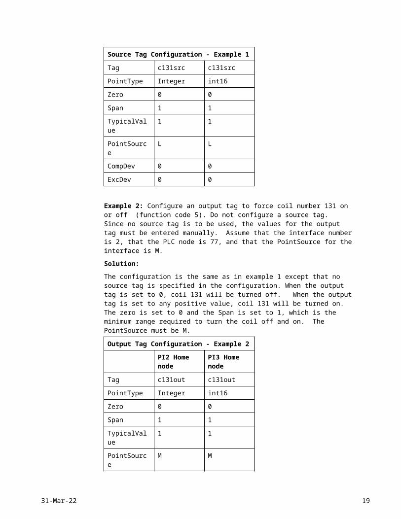
Source Tag Configuration - Example 1
PI2 Home node PI3 Home node
Tag c131src c131src
PointType Integer int16
Zero 0 0
Span 1 1
TypicalValue 1 1
PointSource L L
CompDev 0 0
ExcDev 0 0
Example 2: Configure an output tag to force coil number 131 on or off (function code 5). Do not configure a source tag. Since no source tag is to be used, the values for the output tag must be entered manually. Assume that the interface number is 2, that the PLC node is 77, and that the PointSource for the interface is M.
12 OSI Software, Inc.
Solution:
The configuration is the same as in example 1 except that no source tag is specified in the configuration. When the output tag is set to 0, coil 131 will be turned off. When the output tag is set to any positive value, coil 131 will be turned on. The zero is set to 0 and the Span is set to 1, which is the minimum range required to turn the coil off and on. The PointSource must be M.
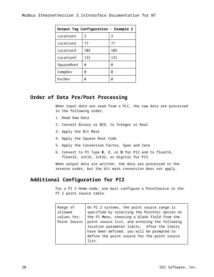
Output Tag Configuration - Example 2
PI2 Home node PI3 Home node
Tag c131out c131out
PointType Integer int16
Zero 0 0
Span 1 1
TypicalValue 1 1
PointSource M M
Location1 2 2
Location2 77 77
Location3 105 105
Location5 131 131
SquareRoot 0 0
CompDev 0 0
ExcDev 0 0
Order of Data Pre/Post ProcessingWhen input data are read from a PLC, the raw data are processed in the following order:
1. Read Raw Data
2. Convert Binary or BCD, to Integer or Real
3. Apply the Bit Mask
4. Apply the Square Root Code
5. Apply the Conversion Factor, Span and Zero
6. Convert to PI Type R, I, or D for PI2 and to float16, float32, int16, int32, or digital for PI3.
When output data are written, the data are processed in the reverse order, but the bit mask conversion does not apply.
Additional Configuration for PI2For a PI 2 Home node, one must configure a PointSource in the PI 2 point source table.
18-May-23 13
Modbus EthernetVersion 3.1xInterface Documentation for NT
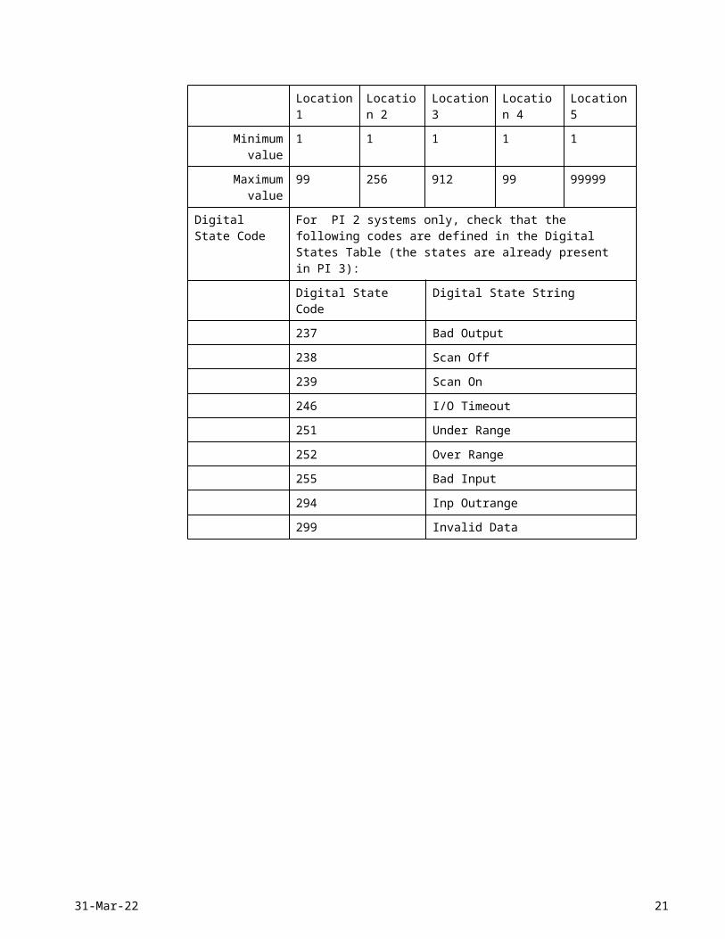
Range of allowed values for:Point Source
On PI 2 systems, the point source range is specified by selecting the PointSrc option on the PI Menu, choosing a blank field from the point source list, and entering the following location parameter limits. After the limits have been defined, you will be prompted to define the point source for the point source list.
Location 1 Location 2 Location 3 Location 4 Location 5
Minimum value 1 1 1 1 1
Maximum value 99 256 912 99 99999
Digital State Code For PI 2 systems only, check that the following codes are defined in the Digital States Table (the states are already present in PI 3):
Digital State Code Digital State String
237 Bad Output
238 Scan Off
239 Scan On
246 I/O Timeout
251 Under Range
252 Over Range
255 Bad Input
294 Inp Outrange
299 Invalid Data
14 OSI Software, Inc.
Hardware and Software All that is requires is a standard network interface card for TCP/IP communication.
18-May-23 15
Modbus EthernetVersion 3.1xInterface Documentation for NT
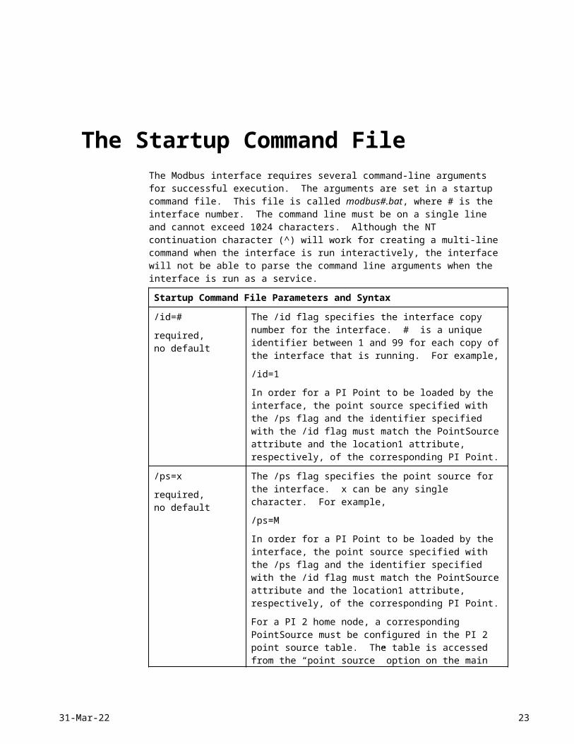
The Startup Command FileThe Modbus interface requires several command-line arguments for successful execution. The arguments are set in a startup command file. This file is called modbus#.bat, where # is the interface number. The command line must be on a single line and cannot exceed 1024 characters. Although the NT continuation character (^) will work for creating a multi-line command when the interface is run interactively, the interface will not be able to parse the command line arguments when the interface is run as a service.
Startup Command File Parameters and Syntax
/id=#
required,no default
The /id flag specifies the interface copy number for the interface. # is a unique identifier between 1 and 99 for each copy of the interface that is running. For example,
/id=1
In order for a PI Point to be loaded by the interface, the point source specified with the /ps flag and the identifier specified with the /id flag must match the PointSource attribute and the location1 attribute, respectively, of the corresponding PI Point.
/ps=x
required,no default
The /ps flag specifies the point source for the interface. x can be any single character. For example,
/ps=M
In order for a PI Point to be loaded by the interface, the point source specified with the /ps flag and the identifier specified with the /id flag must match the PointSource attribute and the location1 attribute, respectively, of the corresponding PI Point.
For a PI 2 home node, a corresponding PointSource must be configured in the PI 2 point source table. The table is accessed from the “point source” option on the main menu of PI 2. For PI 3, a PointSource does not need to be configured.
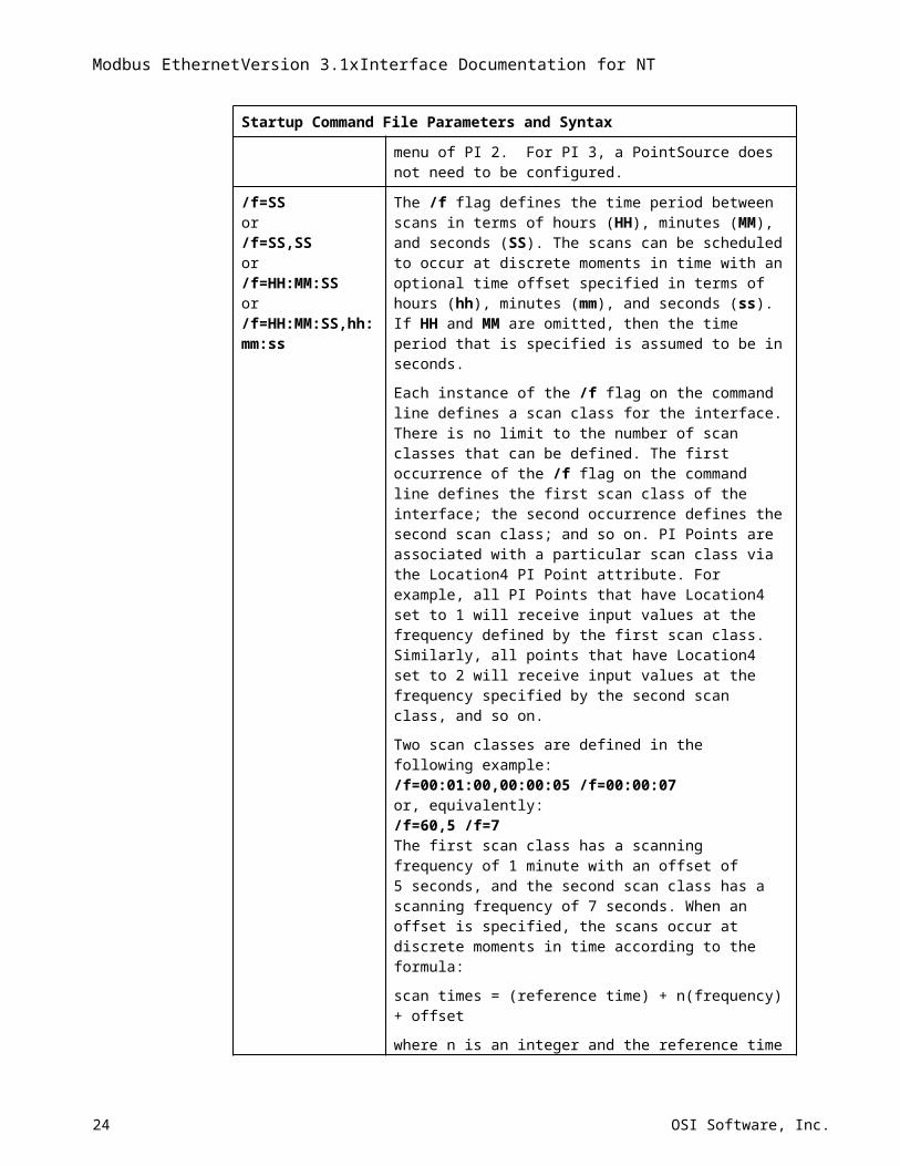
/f=SSor/f=SS,SSor /f=HH:MM:SSor/f=HH:MM:SS,hh:mm:ss
The /f flag defines the time period between scans in terms of hours (HH), minutes (MM), and seconds (SS). The scans can be scheduled to occur at discrete moments in time with an optional time offset specified in terms of hours (hh), minutes (mm), and seconds (ss). If HH and MM are omitted, then the time period that is specified is assumed to be in seconds.
Each instance of the /f flag on the command line defines a scan class for the interface. There is no limit to the number of scan classes that can be defined. The first occurrence of the /f flag on the command line defines the first scan class of the interface; the second occurrence defines the second scan class; and so on. PI Points are associated with a particular scan class via the Location4 PI Point attribute. For example, all PI Points that have Location4 set to 1 will receive input values at the frequency defined by the first scan class. Similarly, all points that have Location4 set to 2 will receive input values at the frequency specified by the second scan class, and so on.
16 OSI Software, Inc.
Startup Command File Parameters and Syntax
Two scan classes are defined in the following example:/f=00:01:00,00:00:05 /f=00:00:07or, equivalently:/f=60,5 /f=7The first scan class has a scanning frequency of 1 minute with an offset of 5 seconds, and the second scan class has a scanning frequency of 7 seconds. When an offset is specified, the scans occur at discrete moments in time according to the formula:
scan times = (reference time) + n(frequency) + offset
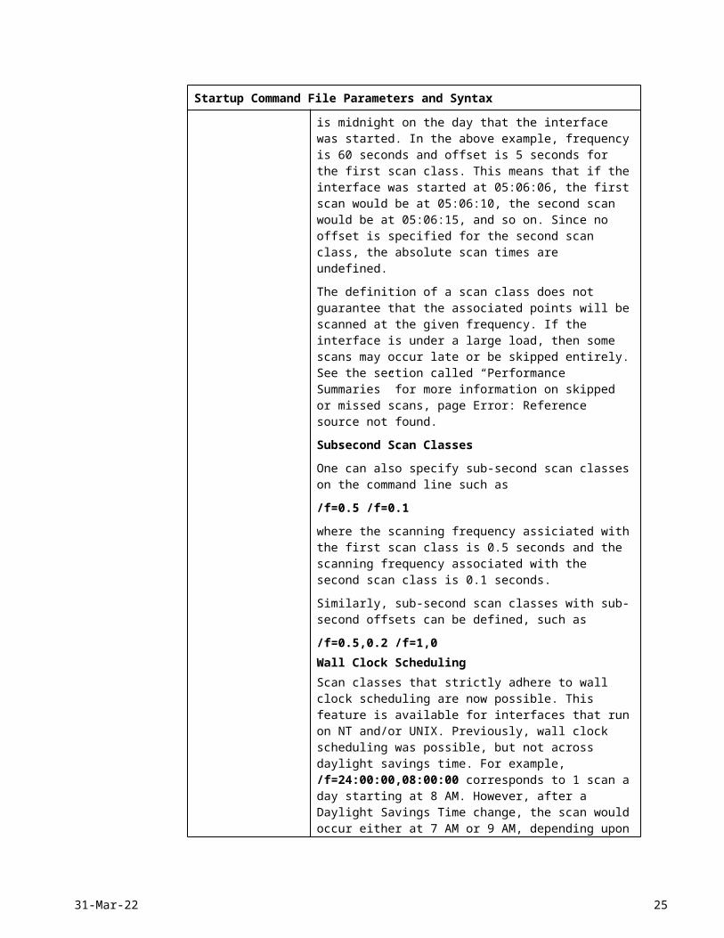
where n is an integer and the reference time is midnight on the day that the interface was started. In the above example, frequency is 60 seconds and offset is 5 seconds for the first scan class. This means that if the interface was started at 05:06:06, the first scan would be at 05:06:10, the second scan would be at 05:06:15, and so on. Since no offset is specified for the second scan class, the absolute scan times are undefined.
The definition of a scan class does not guarantee that the associated points will be scanned at the given frequency. If the interface is under a large load, then some scans may occur late or be skipped entirely. See the section called “Performance Summaries” for more information on skipped or missed scans, page Error: Reference source not found.
Subsecond Scan Classes
One can also specify sub-second scan classes on the command line such as
/f=0.5 /f=0.1
where the scanning frequency assiciated with the first scan class is 0.5 seconds and the scanning frequency associated with the second scan class is 0.1 seconds.
Similarly, sub-second scan classes with sub-second offsets can be defined, such as
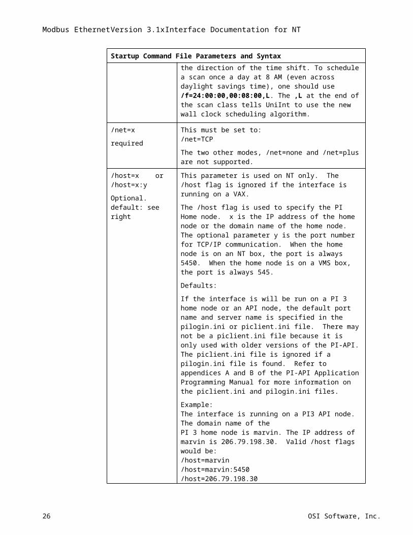
/f=0.5,0.2 /f=1,0Wall Clock SchedulingScan classes that strictly adhere to wall clock scheduling are now possible. This feature is available for interfaces that run on NT and/or UNIX. Previously, wall clock scheduling was possible, but not across daylight savings time. For example, /f=24:00:00,08:00:00 corresponds to 1 scan a day starting at 8 AM. However, after a Daylight Savings Time change, the scan would occur either at 7 AM or 9 AM, depending upon the direction of the time shift. To schedule a scan once a day at 8 AM (even across daylight savings time), one should use /f=24:00:00,00:08:00,L. The ,L at the end of the scan class tells UniInt to use the new wall clock scheduling algorithm.
/net=x
required
This must be set to:/net=TCP
The two other modes, /net=none and /net=plus are not supported.
/host=x or/host=x:y
This parameter is used on NT only. The /host flag is ignored if the interface is running on a VAX.
18-May-23 17
Modbus EthernetVersion 3.1xInterface Documentation for NT
Startup Command File Parameters and Syntax
Optional.default: see right
The /host flag is used to specify the PI Home node. x is the IP address of the home node or the domain name of the home node. The optional parameter y is the port number for TCP/IP communication. When the home node is on an NT box, the port is always 5450. When the home node is on a VMS box, the port is always 545.
Defaults:
If the interface is will be run on a PI 3 home node or an API node, the default port name and server name is specified in the pilogin.ini or piclient.ini file. There may not be a piclient.ini file because it is only used with older versions of the PI-API. The piclient.ini file is ignored if a pilogin.ini file is found. Refer to appendices A and B of the PI-API Application Programming Manual for more information on the piclient.ini and pilogin.ini files.
Example:The interface is running on a PI3 API node. The domain name of the PI 3 home node is marvin. The IP address of marvin is 206.79.198.30. Valid /host flags would be:/host=marvin /host=marvin:5450 /host=206.79.198.30/host=206.79.198.30:5450
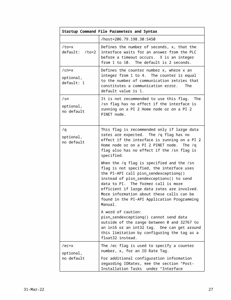
/to=xdefault: /to=2
Defines the number of seconds, x, that the interface waits for an answer from the PLC before a timeout occurs. X is an integer from 1 to 10. The default is 2 seconds.
/cn=x
optional,default: 1
Defines the counter number x, where x an integer from 1 to 4. The counter is equal to the number of communication retries that constitutes a communication error. The default value is 1.
/sn
optional,no default
It is not recommended to use this flag. The /sn flag has no effect if the interface is running on a PI 2 Home node or on a PI 2 PINET node.
/q
optional,no default
This flag is recommended only if large data rates are expected. The /q flag has no effect if the interface is running on a PI 2 Home node or on a PI 2 PINET node. The /q flag also has no effect if the /sn flag is specified.
When the /q flag is specified and the /sn flag is not specified, the interface uses the PI-API call pisn_sendexceptionq() instead of pisn_sendexceptions() to send data to PI. The former call is more efficient if large data rates are involved. More information about these calls can be found in the PI-API Application Programming Manual.
A word of caution: pisn_sendexceptionq() cannot send data outside of the range between 0 and 32767 to an in16 or an int32 tag. One can get around this limitation by configuring the tag as a float32 instead.
/ec=x
optional,no default
The /ec flag is used to specify a counter number, x, for an IO Rate Tag.
For additional configuration information regarding IORates, see the section “Post-Installation Tasks” under “Interface Installation.”
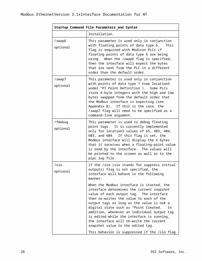
/swap6 This parameter is used only in conjunction with floating points of data type 6. This flag is required with Modicon PLCs if floating points of data
18 OSI Software, Inc.
Startup Command File Parameters and Syntax
optional type 6 are being using. When the /swap6 flag is specified, then the interface will expect the bytes that are sent from the PLC in a different order than the default order.
/swap7
optional
This parameter is used only in conjunction with points of data type 7 (see location3 under “PI Point Definition”). Some PLCs store 4-byte integers with the high and low bytes swapped from the default order that the Modbus interface is expecting (see Appendix B). If this is the case, the /swap7 flag will need to be specified as a command-line argument.
/fdebug
optional
This parameter is used to debug floating point tags. It is currently implemented only for location3 values of 65, 403, 404, 603, and 604. If this flag is set, the Modbus interface will display the 4 bytes that it receives when a floating-point value is read by the interface. The values will be printed to the screen as wall as to the pipc.log file.
/sio
optional
If the /sio (sio stands for suppress initial outputs) flag is not specified, the interface will behave in the following manner:
When the Modbus interface is started, the interface determines the current snapshot value of each output tag. The interface then re-writes the value to each of the output tags as long as the value is not a digital state such as “Point Created.” In addition, whenever an individual output tag is edited while the interface is running, the interface will re-write the current snapshot value to the edited tag.
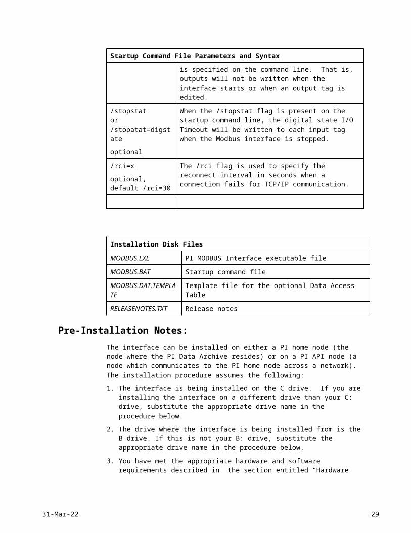
This behavior is suppressed if the /sio flag is specified on the command line. That is, outputs will not be written when the interface starts or when an output tag is edited.
/stopstator/stopatat=digstate
optional
When the /stopstat flag is present on the startup command line, the digital state I/O Timeout will be written to each input tag when the Modbus interface is stopped.
/rci=x
optional,default /rci=30
The /rci flag is used to specify the reconnect interval in seconds when a connection fails for TCP/IP communication.
Installation Disk Files
MODBUS.EXE PI MODBUS Interface executable file
MODBUS.BAT Startup command file
MODBUS.DAT.TEMPLATE
Template file for the optional Data Access Table
RELEASENOTES.TXT Release notes
18-May-23 19
Modbus EthernetVersion 3.1xInterface Documentation for NT
Pre-Installation Notes:The interface can be installed on either a PI home node (the node where the PI Data Archive resides) or on a PI API node (a node which communicates to the PI home node across a network). The installation procedure assumes the following:
1. The interface is being installed on the C drive. If you are installing the interface on a different drive than your C: drive, substitute the appropriate drive name in the procedure below.
2. The drive where the interface is being installed from is the B drive. If this is not your B: drive, substitute the appropriate drive name in the procedure below.
3. You have met the appropriate hardware and software requirements described in the section entitled “Hardware and Software” above. Also, double check: that the PLC is in RTU mode, NOT ASCII mode.
4. For a PI3 home node: The PI Firewall Database and the PI Proxy Database are configured so that the interface is allowed to write data to the PI Data Archive. See “Modifying the Firewall Database” and “Modifying the Proxy Database” in the Pi Data Archive Manual. If the interface cannot write data to the PI Data Archive owing to permission problems, an error –10401 will occur. Note that /host=localhost:5450 in the modbus#.bat file corresponds to the loopback node 127.0.0.1, which is present by default in the Firewall and Proxy Databases.
5. For a PI2 home node: The client must be allowed write access to the PI2 Data Archive. Read and write access is controlled in PI2 with the pisysdat:piserver.dat file.
Installation Procedure:1. Create the following directory:
c:\PI\interfaces\modbus#\ # should be replaced by a number between 1 and 99, inclusive. # should correspond to the interface number that is specified using the /id flag in the modbus#.bat file. The user should create one directory for each version of the interface that he or she wishes to implement. If the user wishes to restrict the range of registers, coils, or inputs that the interface is allowed to access from a given PLC, the user may create an optional Data Access Table at this time. A sample Data Access Table file is provided on the installation disk (MODBUS.DAT.TEMPLATE). The full implementation procedure for the Data Access Table is described under the section entitled “Data Access Table.” The Data Access Table can be implemented at a later time since the absence of the table does not adversely affect interface operation. Note: The interface does not enforce the modbus# naming convention for the executable file, the startup command file (batch file), or the directory. These can be given any legal name for the operating system. However, if the user wishes to run the interface manually and the user does not use the naming convention suggested in this manual, he or she will need to change the path to the executable on the command line in the batch file. The interface does enforce the naming convention for the Data Access Table. That is, the Data Access Table must be called modbus#.dat, where # is the interface number specified by the /id flag in the batch file. Also error messages in the pipc.log file will be prepended by modbus #>, independent of the name of the executable file, batch file, and directory.
2. Insert the installation disk, and execute the following commands from an MsDos prompt:
20 OSI Software, Inc.
copy b:\modbus.exe c:\PI\interfaces\modbus#\modbus#.execopy b:\modbus.bat c:\PI\interfaces\modbus#\modbus#.batAs mentioned above, # should correspond to the interface number that is specified using the /id flag in the modbus#.bat file.
3. If the dynamic linked libraries (.dll files) provided on the installation disk are not in your c:\winnt\system32 directory or if the dynamic linked libraries in your system directory are older than the libraries on the installation disk, copy the libraries from the installation disk to your system directory. Your system directory may be on a drive other than your C drive.Remove the installation disk.
4. Modify the command-line arguments in your modbus#.bat file to customize your interface. For example,
..\interfaces\modbus1\modbus1.exe /id=1 /q /ps=M /net=TCP /f=00:01:00 The command line must be on a single line and cannot exceed 1024 characters (1 kilobyte). This is a limitation set by the interface, not by the NT Operating system. The command-line arguments are discussed earlier in this manual. Next, complete steps 5 and 6 to start the interface as a service or complete steps 7 and 8 to start the interface manually (interactive mode). Manual startup is recommended the first time that the interface is started because manual startup is easier to troubleshoot.
To run as a service, complete steps 5 and 6:
The procedure for installing the Modbus interface as a service depends upon whether or not Bufserv is being used. Once the interface has been installed as a service, the procedure for starting, stopping, and removing the interface as a service is the same whether or not Bufserv is used. The purpose of the Bufserv utility is to continue to collect data from an interface in the event that the PI Data Archive is shut down for some reason. For example, if the Modbus interface is installed on the PI home node and the PI Data Archive is shut down for an upgrade, the Bufserv utility on the PI home node will buffer the data in a file until the PI Data Archive is brought back online. Another possibility is that the Modbus interface is installed on an API node. If there are problems with the PI home node, then the Bufserv utility on the API node will buffer the data in a file until the PI home node is brought back online.
The procedure for installing the interface in conjunction with the Bufserv Utility assumes that the user has Bufserv 1.04 or higher because the procedure implicitly assumes that Bufserv will be installed as a service. The actual installation of the Bufserv Utility itself is not discussed. For these instructions, the user is referred to the PI-API Bufserv 1.x Release Notes. Also, the installation procedure below does not discuss the details related to shutdown events that the user should be aware of when the Bufserv Utility is used. Once again, refer to the PI-API Bufserv 1.x Release Notes for more information.
5. One can get help for installing the interface a service at any time by typing the following:
Modbus# -helpNote that the –query flag that is described when help is invoked is not implemented at this time.
The modbus# service can be installed either as a manual or an automatic service. Automatic services are started automatically when the NT operating system is rebooted. This feature is useful in the event of a power failure. To install the interface as a manual service, execute the following command from the modbus#\ directory.
18-May-23 21
Modbus EthernetVersion 3.1xInterface Documentation for NT
Without Bufserv:modbus# -install -depend tcpipWith Bufserv:modbus# -install -depend “tcpip bufserv”
To install the interface as an automatic service, execute the following command from the modbus#\ directory.
Without Bufserv:modbus# -install –auto -depend tcpipWith Bufserv:modbus# -install –auto -depend “tcpip bufserv”Check the Microsoft Windows NT services control panel to verify that the service has been successfully added. One can use the services control panel at any time to change the modbus# service from an automatic service to a manual service or vice versa. Once the modbus# service has been installed, the rest of the procedure is the same whether or not Bufserv has been implemented. The modbus# service can be started from the services control panel or by executing the following command from the modbus#\ directory:modbus# -startA message will be echoed to the screen informing the user whether or not the interface has been successfully started as a service. If the service is successfully started, the interface will attempt to read the command-line arguments from the modbus#.bat file. For this to succeed, the root name (the part of the file name before the .exe and .bat extensions) of the batch file must be the same as the root name of the executable. Also, the batch file and the executable file must be in the same directory. If the interface is unable to read the command-line arguments or if the command-line arguments that the interface reads are invalid, the service will terminate with no error messages echoed to the screen. For this reason, the user MUST check the pipc.log file to verify that the interface is running correctly. In the pipc.log file, messages pertaining to the modbus interface will be prepended by Modbus #>. The location of the pipc.log file is determined by the PIHOME entry in the pipc.ini file. The pipc.ini file is located in the Winnt directory. Usually, the pipc.log file will reside in the c:\pipc\dat\ directory. If the service was successfully started, the user can verify that the service is still running from the services control panel. If the service has been terminated, the reason for its termination will be given in the pipc.log file. If the service is still running, the user can use c:\PI\bin\apisnap.exe or Processbook to verify that data is being successfully transferred to the PI Data Archive.The modbus# service can be stopped at any time by issuing the following command:modbus# -stopThe modbus# service can be removed bymodbus# -remove
6. If the modbus# service is installed as a manual service on the PI home node, the user may wish to edit the c:\PI\adm\pisrvsitestart.bat and the c:\PI\adm\pisrvsitestop.bat command files. These command files are invoked only when the PI data archive is started and stopped as a manual service with the c:\PI\adm\pisrvstart.bat and the c:\PI\adm\pisitestop.bat command files. In the c:\PI\adm\pisrvsitestart.bat file, make sure that the second to last line ends in& wait 5000
22 OSI Software, Inc.
If not, append “& wait 5000” to the end of the line. In the same file, add the following command just above “:theend”C:\PI\interfaces\modbus#\modbus# -start & wait 5000Add the following command to the c:\PI\adm\pisrvsitestop.bat file just above “:theend”C:\PI\interfaces\modbus#\modbus# -stopNote that the full path name to the modbus# executable must be given in both the c:\PI\adm\pisrvsitestart.bat and the c:\PI\adm\pisrvsitestop.bat command files.
To run in interactive mode, complete steps 7 and 8:
7. Execute the following command from an MsDos prompt:cd c:\PI\interfacesstart "Modbus#" modbus#\modbus#.bat A new MsDos window will appear, and the user will see several messages echoed to the screen. Then the messages will simply stop. The user will not regain a command prompt on the MsDos window until the interface has been stopped. The interface is stopped by typing CONTROL-C while the MsDos window is selected. The user can use c:\PI\bin\apisnap.exe or Processbook to verify that data is being successfully transferred to the PI Data Archive.Check whether there are any error messages to verify successful execution of the interface. Messages that are sent to the screen are also sent to the pipc.log file. Check the pipc.log file. Some messages are written to this file that are not echoed to the screen when the interface is started up. Messages in the pipc.log file that pertain to the modbus interface will be prepended by Modbus #>. The location of the pipc.log file is determined by the PIHOME entry in the pipc.ini file. The pipc.ini file is located in the Winnt directory. Usually, the pipc.log file will be placed in the c:\pipc\dat\ directory.
8. If you plan on starting both the PI Data Archive and the Modbus interface manually, you may wish to start the Modbus interface along with the PI data archive. To do this you must edit the c:\PI\adm\pisitestart.bat command file (there is no such thing as a c:\PI\adm\pisitestop.bat command file). Make sure that the last line of the c:\PI\adm\pisitestart.bat file ends in:& wait 5000 If not, append “& wait 5000” to the end of the line. In the same file, add the following two commands:
echo Starting Modbus# Interface start "Modbus#" /min ..\interfaces\modbus#\modbus#.bat & wait 5000
The Modbus# interface should now be started in interactive mode. The /min flag minimizes the MsDos window that is created when the Modbus interface is executed.
Post-Installation Tasks
IORates
An IO Rate Tag can be configured to receive 10 minutes averages of the total number of events per minute that are received by the interface. The IO Rate will appear to be zero for the first 10 minutes that the interface is running.
To implement an IO Rate Tag, perform the following steps:
18-May-23 23
Modbus EthernetVersion 3.1xInterface Documentation for NT
1. Create an IO Rate Tag. To create an IO Rate tag called “sy:mod001”, for example, create a file called Iorates.dif similar to:
Iorates.dif
@table pipoint@ptclas classic@stype keyword@mode create,ttag, sy:mod001Descriptor, "Modbus Rate Tag #1"zero, 0span, 100TypicalValue, 50PointType, float32PointSource, LCompressing, 0 @ends
Adjust the Zero, Span, and TypicalValue as appropriate and then type the command:C:\pi\adm\piconfig < iorates.datto create the IO Rate Tag.
2. Create a file called iorates.dat in the PIHOME\dat directory. The PIHOME directory is defined either by the PIPCSHARE entry or the PHOME entry in the pipc.ini file, which is located in the Windows directory. The PIPCSHARE entry takes precedence. Since the PIHOME directory is typically C:\PIPC, the full name of the iorates.dat file will typically be C:\PIPC\iorates.dat.Add a line in the iorates.dat file of the form:sy:mod001, xwhere x corresponds to the event counter specified by the /ec=x flag in the startup command file of the interface. x can be any number between 1 and 34 or between 51 and 200, inclusive. To specify additional rate counters for additional copies of the Modbus interface, create additional tags and additional entries in the iorates.dat file as appropriate. The event counter, /ec=x, should be unique for each copy of the interface.
3. Set the /ec=x flag on the startup command file of the interface to match the event counter in the :iorates.dat file.
4. The interface must be stopped and restarted in order for the IO Rate tag to take effect. IORates will not be written to the tag until 10 minutes after the interface is started.
The 10-minute rate averages (in events/minute) can be monitored, for example, on a ProcessBook trend.
24 OSI Software, Inc.
MODBUS Interface System Administration Starting the MODBUS InterfaceAutomatic service startup
If the Modbus interface was configured as an automatic service in step 6 of the installation procedure, then the Modbus interface will automatically start after the NT system reboots. This configuration is useful in the event of a power failure.
Manual service startupIf the Modbus interface was configured as a manual service and the PI system was also configured as a manual service, then the Modbus interface can be started along with the PI system when the following command file is executed from the adm\ directory (assuming that step 6 of the installation procedure was completed):pisrvstart.bat
If you wish to start a manual Modbus service separately from the PI Data Archive, execute the following command from the modbus#\ directory:
modbus# -start
Interactive startupIf both PI and the Modbus interface are started interactively, one can start both of them with the pistart.bat
command file, assuming that step 8 of the installation procedure was completed.
Alternatively, one can start the interface independently of the PI Data Archive by typing the following command from the interfaces\ directory:start "Modbus#" modbus#\modbus#.bat
Or one can issue the following command from the interfaces\ directory:modbus#\modbus#.batWhen start “Modbus#”… command is used, a new MsDos window is created.
Stopping the MODBUS InterfaceIf the Modbus interface was configured as an automatic or a manual service in steps 5 and 6 of the installation procedure and if the PI system was also configured as an automatic or manual service, then the modbus# service is stopped along with the PI system by executing the following command file from the adm\ directory:pisrvstop.bat
18-May-23 25
Modbus EthernetVersion 3.1xInterface Documentation for NT
This assumes that both steps 6 and/or 7 of the installation procedure have been completed.
Alternatively, one can stop the modbus# service independently from stopping the PI system by executing the following command from the modbus#\ directory: modbus# -stop
or one can stop the modbus# service from the services control panel.
If the Modbus interface was started in interactive mode, one can stop the Modbus interface by 1) selecting the MsDos window that corresponds to the modbus# interface, and 2) holding down the control key while typing the letter c (note that there is no pisitestop.bat file to correspond to the pisitestart.bat file).
Registering the Modbus Interface as a Windows NT Service
Manual servicesFrom the modbus#\ directory, execute the command.
Without Bufserv:modbus# -install -depend tcpipWith Bufserv:modbus# -install -depend “tcpip bufserv”
Check the services control panel to verify that the modbus# service has been added. See the PI-API Bufserv 1.x Release Notes for the installation instructions for Bufserv.
Automatic servicesFrom the modbus#\ directory, execute the command:
Without Bufserv:modbus# -install –auto -depend tcpipWith Bufserv:modbus# -install –auto -depend “tcpip bufserv”
Check the services control panel to verify that the modbus# service has been added. See the PI-API Bufserv 1.x Release Notes for the installation instructions for Bufserv. The Modbus interface will now start automatically when the computer is rebooted.
Removing the Modbus Interface as a Windows NT ServiceFrom the modbus#\ directory, execute the command:modbus# -remove
Check the services control panel to verify that the modbus# service has been removed.
Status, Warning, And Error MessagesSuch messages will be written to the pipc.log file. This file should be checked to verify successful execution of the interface because not all error messages are echoed to the screen. The location of this file is determined by the PIHOME entry in the pipc.ini file, which is located in the Winnt directory (for more information see the description of the subroutine pilg_putlog in the PI Application Programming Interface manual). For example, if the PIHOME entry is c:\PIPC, then the pipc.log file will be located in the c:\PIPC\dat directory.
26 OSI Software, Inc.
Data Access TableFor security purposes, the user may wish to restrict the range of registers, coils, etc., that the Modbus Interface can read from or write to. The accessible ranges can be configured in an optional data access table. The accessible registers, coils, etc., can be configured differently for different PLC nodes. If no Data Access Table is found by the interface, default minimum and maximum values will be assigned.
One Data Access Table can be configured for each version of the interface that is running. This file must be called Modbus#.dat, where # should be replaced by the interface number as specified by the /id flag on the startup command line of the interface. The Modbus#.dat file should be placed in the PIHOME/dat directory. The PIHOME directory is determined by the PIHOME or the PIPCSHARE entry in the pipc.ini file (located in the Winnt directory). The PIPCSHARE entry takes precedence when both PIHOME and PIPCSHARE are defined. For example, if the PIHOME entry is c:\PIPC, then the Modbus#.dat file should be placed in the c:\PIPC\dat directory.
If the data access table is added, deleted or modified, the interface must be restarted before the new values will take effect.If the user configures a PI tag (say mb:read.1) with a coil or register address that is out of range, the Modbus interface will respond with the following error message:Modbus #> Load PI point Failed, Cannot access a valid register (or address), for Tag: mb:read.1
An example of a data access table file is given below. Note that comments lines are denoted by a * character in the first column. One must create this file manually if one wishes to implement this functionality. ** Template file for data access table* 26-Aug-97 GWM, OSI Software, Inc. ** "*" points serve as comment markers.** This file is used to assign the minimum and maximum* coil/register addresses.** If no Data Access Table is provided, the following default * ranges are used for the given items:* * ITEM: DEFAULT VALUE:* -------------------------- ------------* The Minimum Register/Coil Value 1* The Maximum Register/Coil Value 65,536** SYNTAX*
18-May-23 27
Modbus EthernetVersion 3.1xInterface Documentation for NT
* The syntax is:* 'Node','Function code','Minimum','Maximum'** ------------------* EXAMPLE FOR MODBUS* For Modicon hardware, function codes 1 and 5 begin at coil 1, * function code 2 begins at input 10001, function code 3 and 6 * begin at holding register 40001, and function code 4 begins* at holding register 30001. To restrict access to certain * coils, registers, etc., offset values from 0, 10000, 40000,* and 30000 need to be provided. To restrict data access to* the first 96 coil, registers, etc., for each function code* and for PLC node 1, the following syntax is used:** Uncomment the next six lines to implement this example* 1,1,1,96* 1,2,1,96* 1,3,1,96* 1,4,1,96* 1,5,1,96* 1,6,1,96** ---------------------* Note that PLC node 1 is referenced at the beginning and end* of each series of numbers.* ----------------------*** end of Data Access File
28 OSI Software, Inc.
Appendix A Modbus Message Packets
The message packets that are described below correspond to the Modbus protocol. These packets are embedded within TCP/IP framing.
Function codes 1-4: message packet sent to PLCByte 0: PLC node address
Byte 1: Function code.
Byte 2: High-order byte specifying the first coil or register address.
Byte 3: Low-order byte specifying the first coil or register address.
Byte 4: High-order byte specifying the number of coils or registers to be accessed.
Byte 5: Low-order byte specifying the number of coils or registers to be accessed.
Function codes 1-4: message packet returned by PLCByte 0: PLC node address.
Byte 1: Function code.
Byte 2: Number of bytes of data returned.
Byte 3: Data
Byte 4: Data
…
Byte N: Data
Function codes 5-6: message packet sent to PLC (except for data type 4)Byte 0: PLC node address.
Byte 1: Function code.
Byte 2: High-order byte of coil or register address.
Byte 3: Low-order byte of coil or register address.
Byte 4: High-order data byte sent to coil or register.
Byte 5: Low-order data byte sent to coil or register.
Function codes 5-6: message packet sent to PLC (data type 4)Byte 0: PLC node address.
18-May-23 29
Modbus EthernetVersion 3.1xInterface Documentation for NT
Byte 1: Function code.
Byte 2: High-order byte of coil or register address.
Byte 3: Low-order byte of coil or register address.
Byte 4: High-order data byte sent to coil or register.
Byte 5: Low-order data byte sent to coil or register.
Byte 6: High-order data byte sent to coil or register.
Byte 7: Low-order data byte sent to coil or register.
Function codes 5-6: message packet returned by PLCThe PLC returns the same bytes that were received.
Function code 16: message packet sent to PLCByte 0: PLC node address.
Byte 1: Function code.
Byte 2: High-order byte specifying the first register address to be written to.
Byte 3: Low-order byte specifying the first register address to be written to.
Byte 4: High-order byte specifying the number of registers to be accessed, which is always set to 0 for OSI Software’s Modbus interface to the PI system.
Byte 5: Low-order byte specifying the number of registers to be accessed, which is always set to 2 for OSI Software’s Modbus interface to the PI system.
Byte 6: Number of bytes of data to be sent to PLC.
Byte 7: High-order data byte sent to first register.
Byte 8: Low-order data byte sent to first register.
Byte 9: High-order data byte sent to second register.
Byte 10: High-order data byte sent to second register.
Function code 16: message packet returned by PLCThe PLC returns the first 6 bytes that were received (bytes 0 to 5).
30 OSI Software, Inc.
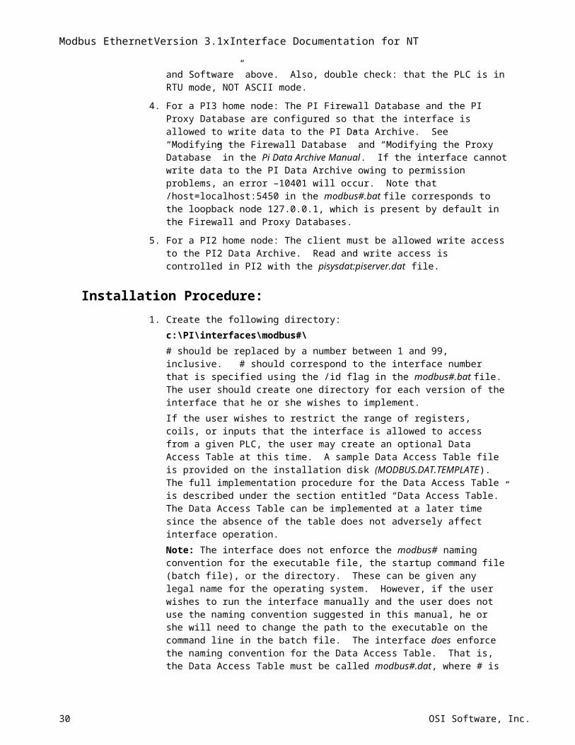
Appendix BFloating Point Representation
The manner in which PLCs store floating-point numbers vary. As a result, the Modbus commands that are needed to retrieve floating point values will also vary from PLC to PLC. The user can specify the manner in which the PLC stores a floating point with the data type parameter that is discussed under “Point Definition” earlier in this manual.
_______________________________________________________________________
NOTE: To make matters more complicated for the software developer, different operating systems (e.g. NT, VAX, UNIX) store IEEE floating point numbers differently. Standard 4-byte IEEE floating points on Intel NT are represented as follows:
byte 3: S MSBE E E E E E E
byte 2: LSBE MSBF F F F F F F
byte 1: F F F F F F F F
byte 0: F F F F F F F LSBF
where,
S = sign bit (1 = -)
MSBE = most significant bit exponentLSBE = least significant bit exponentMSBF = most significant bit fractionLSBF = least significant bit fraction
For example, the number 1 is stored as a floating-point number by:
byte 0 = 0 byte 1 = 0 byte 2 = 0x80 byte 3 = 0x3f
where 0x80 and 0x3f are hexadecimal numbers.
________________________________________________________________________
All floating-point values will be returned in two registers. For purposes of discussion, the “low-order register” will contain bytes 0 and 1, and the “high-order register” will contain bytes 2 and 3. This definition is somewhat arbitrary because the byte order is reversed, for example, on VAX platforms. Hence the “low” and “high” order bytes are swapped. Also, there is no good reason to consider byte 3 (the byte with the exponent) of higher order than byte 1 or byte 0 (bytes containing the fraction).
Some PLC’s will send the low register back first and then the high register, while other PLC’s will send the high register back first and then the low register. The order in which the Modbus interface expect the bytes is different for each data type (see below).
The interface currently supports 3 different methods of reading and writing IEEE floating point numbers. Data types 4, 5 and 6 (defined in the Location3) are IEEE floating points.
18-May-23 31
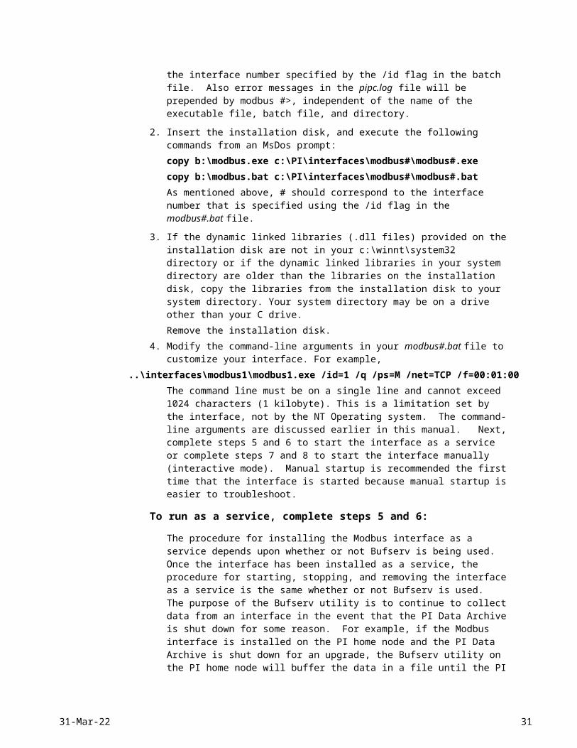
Modbus EthernetVersion 3.1xInterface Documentation for NT
The interface can also read Sieman type floating point values (data type 8), but writes of Siemen floats are not supported. 4-byte integers (data type 7) are also discussed below.
Floating Point, Data Type 4:This type of PLC maps a single register to 2 different registers that contain the floating-point value. For example register 235 could point to the floating-point value contained in registers 625 and 626, and register 236 could point to the floating-point value contained in registers 888 and 889. For the request sent to the PLC, the number of data registers specified will be 1 per floating point. By default the Modbus Interface expects the low order register first followed by the high order register. The Fisher Remote Operational Controller (ROC) Emulation uses this type of floating point.
Floating Point, Data Type 5:This type of PLC stores a floating point in two consecutive registers; for example registers 625 and 626. The interesting thing about this floating point type is that for each request sent to the PLC, the number of data registers specified is 1 per floating point. By default, the Modbus interface expects the low order register first followed by the high order register. The SOLAR APRIL-5000 PLC uses this type of floating point.
Floating Point Type 6:This type of PLC also stores a floating point in two consecutive registers. However the request to the PLC must specify 2 data registers per floating point. The default is to expect the high order register first followed by the low order register. The GE 9070 and Micro Motion Mass Flow Meters return the bytes in this order. Modicon PLCs return the low order register first followed by the high-order register. Hence, the /swap6 flag should be specified in the startup command file for Modicon PLCs.
Data type 7, Binary data, 4-byte integer, Support of floating points represented as 4-byte integers.
Certain devices, such as the Motherwell Controls Series 5000 Tank Gauging System, represent floating point numbers in an integer format. These values require division by a conversion factor to convert them from integers to their proper floating point value. For example, the floating-point value of 16.4 can be represented by a 2 byte integer containing the value of 164: byte0 = 0, byte1 = 164 (decimal). A conversion factor of 10 is used (the raw value is divided by 10) to convert the value to 16.4. A floating-point value of -16.4 can be represented by a 2 byte integer containing -164; byte0 = 255, byte1 = 92. Again the value is divided by the conversion factor, 10, to yield -16.4. The integer range for 2 byte integers is (-32768) to (32767).Four (4) byte integers can also be used to hold floating point numbers. The same conversion equation that applies to 2 byte integers applies to 4 byte integers as well. Data type 7 is used to indicate that data will be 4 byte integer values. The integer range for 4 byte integers is (-2147483648) to (2147483647).The Square Root Code should be set to 3 to indicate the integer to floating point conversion as described above. The appropriate Conversion Factor should be entered and the Point Type should be R. For integer representation, only the following Location3 entries are supported at the present time: 103, 104, 703, 704 and (for write) 106, 706.
The default is for the Modbus interface to expect the high order register first.
Data type 8, Siemens Floating-Point Representation
Siemens Floating points are supported only for inputs.The Siemens PLC uses a special bitmap representation. The float bitmap
32 OSI Software, Inc.
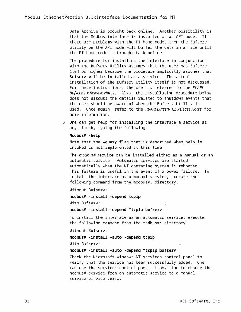
representation is listed below:Bits map: 31 30 29 28 27 26 25 24 23 22 21 20 ....................................01 00Siemens: S X X X X X X X S M M M ...................................M Mwhere: S=Sign Bits, X=Exponent Bits, and M=MantissaBit31 is the sign bit of the exponent,Bit30 to Bit24 represent a decimal value of ..... (64 ... 1) and are used to compose the exponent,Bit23 is the sign bit of the mantissa,bit22 to Bit00 represent a decimal value of ..... and are used to compose the mantissa. The following formula is used to generate the decimal value from the four bytes that are sent:
Where Mantissa is formed as follows:
and the Exponent:
The default is for the Modbus interface to expect the high order register first
Function code 65
Some PLC’s are able to understand function code 65, which is a non-standard modbus function code. One type of PLC that understands function code 65 is called an HTMUX box. If such a PLC receives function code 65, it knows that a 4-byte floating point should be returned.
Each register that can be read with function code 65 contains 4 bytes of information. Standard registers can hold only two bytes of information. Function code 65 is similar to data type 4 above, except that there is no need to map a single register to two different registers. Each register can already hold 4 bytes.
18-May-23 33
Modbus EthernetVersion 3.1xInterface Documentation for NT
Appendix CCurrently Supported PLC’s
Modicon 984 Series PLC's
Modicon Quantum PLCs
Honeywell 620 Series PLC's
GE 9070 PLC's
GE Speedtronic Mark V control system
Rosemont Hydrostatic Interface Unit (HIU) Tank Gauging System
SOLAR APRIL-5000 PLC's
Fisher Remote Operational Controller (ROC) Emulation
Chessel PLC
Field Electronic Limited PLC 2000
Micro Motion ELITE Model RFT9739 Transmitter (Mass Flow Meter)
ESC8816 Environmental Monitor
Motherwell Controls Series 5000 Tank Gauging System
Siemens S5 PLC
Omni Flow Computers, Series 6000
Fisher-Rosemount ValveLink VL2030 software
SquareD PLC through Network Interface Module CRM-570The SquareD PLC requires non-standard setup. A customer who set up communication to a SquareD PLC sent the following e-mail message after solving the communication problems that he was having: “The problem lies with the setting of the NIM. Port 0 (connected to PI-API node) should set to SY/MAX mode, whereby port 1 (connected to PLC processor) should set to Application mode #2.” Opto22
34 OSI Software, Inc.
Appendix DTrouble shooting – Using Modbus Simulators
Frequently, problems with incorrect values being read by the Modbus Interface can be resolved if the user can read the PLC registers independently of the Modbus interface. For example, the user may not know how his or her particular PLC stores floating-point numbers. Many PLC’s store floating point numbers in two consecutive registers, but this is not always the case. It is important to know how the PLC stores floating point numbers because one needs to specify a data type for the PI Point. For a given data type, the Modbus interface assumes that the PLC stores data in a particular way. If the user can display the register data with an independent program, then the user can determine whether or not the values correspond to the expected floating-point number, assuming that the user is familiar with floating-point representations.
The user can download Modscan or Modscan32 from WinTECH Software’s website: http://www.win-tech.com/. Modscan and Modscan32 can read registers, coils, etc., from a PLC across an Ethernet connection. The user may also be interested in Modsim or Modsim32, available on the same web site. Modsim and Modsim32 simulate a PLC device.
Troubleshooting – Error MessagesError messages are written to the pipc.log file. Do not solely rely upon error messages that are written to the screen.
Troubleshooting – Exception ResponsesA list of exception code responses that can be returned from a PLC is given in appendix F.
18-May-23 35
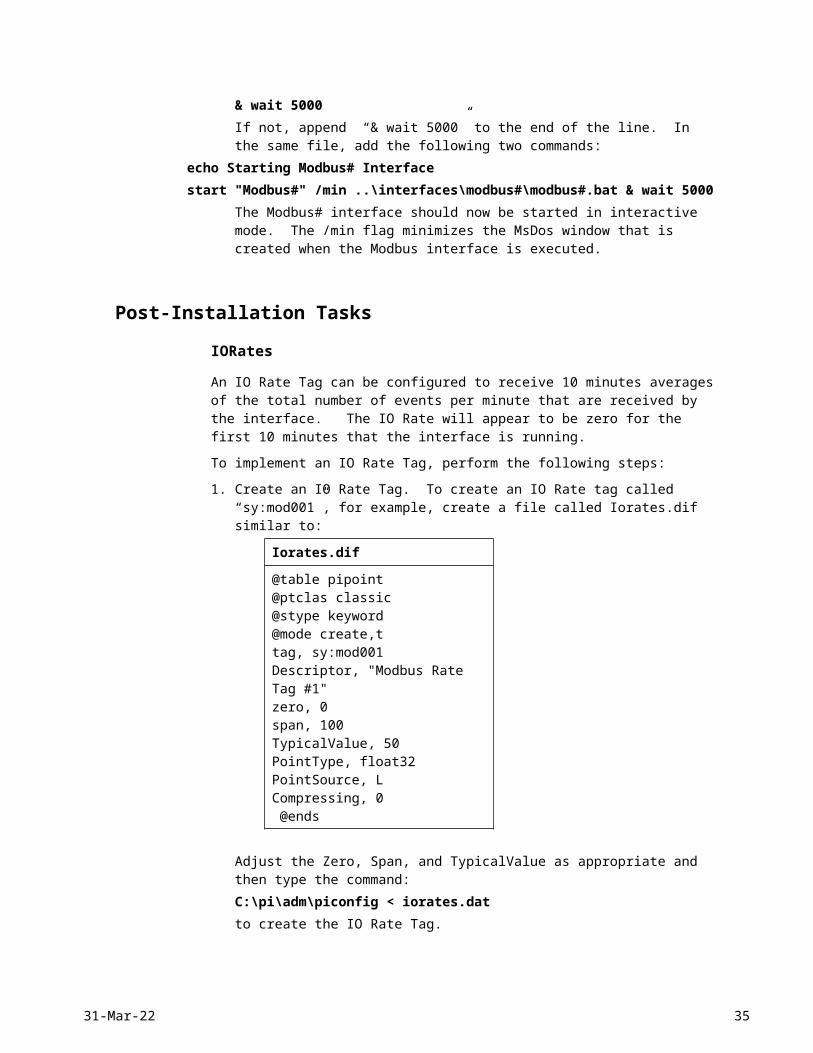
Modbus EthernetVersion 3.1xInterface Documentation for NT
Appendix EDifferences between Versions 2.x and 3.x of the Modbus Interface1. The data conversion options for SquareRoot of 1 and 2 have been changed for output tags. The
previous conversions are shown in bold in the following table:
SquareRoot=1Convers0 andConvers1
Two-step operation for input tags: Value = (Value)0.5
Value = [ (Value - InstZero)/ Convers ] * Span + ZeroTwo-step operation for output tags: Value = (Value)0.5
Value = [ (Value - Zero)/Span] *Convers + InstZero
SquareRoot=2Convers0 orConvers1
Two-step operation for input tags: Value = (Value)2
Value = [ (Value - InstZero)/ Convers ] * Span + ZeroTwo-step operation for output tags: Value = (Value)2
Value = [ (Value - Zero)/Span] *Convers + InstZero
2. Although serial based communication is not officially supported for the Modbus Ethernet interface, serial-based communication can be selected by setting /net=none on the command line. If serial-based Modbus communication is selected (/net=none), the InstrumentTag field can now be used to assign a serial port individually to each PI Point. This allows multiple serial ports to be accessed by a single implementation of the interface. The /dn flag overrides the serial port that is specified in the InstrumentTag field.
3. Version 3.x supports TCP/IP-based Modbus communication. The IP address of the PLC is assigned in the InstrumentTag field.
4. Version 3.x does not officially support serial-based communication or Modbus Plus communication.
36 OSI Software, Inc.
Appendix FPLC Exception Responses
Exception responses are returned to the interface from the PLC when there is an operational or programming error associated with a command from the interface. A list of possible exception response codes is shown below.
01 Illegal function
02 Illegal data address
03 Illegal data value
04 Failure in associated device
05 Acknowledge
06 Busy, rejected message
07 NAK-Negative Acknowledgment
08 Memory parity error
18-May-23 37
Modbus EthernetVersion 3.1xInterface Documentation for NT
Revision HistoryDate Author Comments
26-Jun-98 GWM Created using Modbus 2.x manual as a template
4-Dec-98 GWM Eliminated all referenced to running the interface on VMS and stated throughout this manual that version 3.x of the interface should not be used for serial-based communication or Modbus Plus communication.
18-Apr-00 GWM Since serial-based communication and modbus plus communication is not officially supported for this interface, the configuration details for these communication modes have been eliminated from this manual. The manual has been streamlined to focus only on Modbus Ethernet communication.
17-Oct-00 GWM The Modbus interface can now read string data into string tags. The Modbus interface now supports sub-second scan classes.
38 OSI Software, Inc.