Crowcon Xgard Type 3, Type 4 & Type 5 Fixed Gas Detectors - Spec Sheet
1 | P a g e
Engineering Document
Xgard Bright Public Modbus Interface
Doc No. BJ-ENG-0006
Issue No. v1.2
Date 24/07/2015
Prepared By: Echo.Xue
Approved By:
Report Title :
XgardBright Public Modbus Interface
Approvals 1: Date:
2: Date:
3: Date:
4: Date:
© Crowcon 2012
2 | P a g e
Engineering Document
Xgard Bright Public Modbus Interface
Doc No. BJ-ENG-0006
Issue No. v1.2
Date 24/07/2015
Prepared By: Echo.Xue
Approved By:
Change History
Issue Change Author Date
1 First release Echo Xue
2 Add Registers Echo Xue 19/06/2015
3 Modification Echo Xue 24/07/2015
3 | P a g e
Engineering Document
Xgard Bright Public Modbus Interface
Doc No. BJ-ENG-0006
Issue No. v1.2
Date 24/07/2015
Prepared By: Echo.Xue
Approved By:
Contents
1. Introduction ......................................................................................................................... 4
2. Modbus Interface .............................................................................................................. 5
2.1. Slave Address .................................................................................................................. 5
2.2. Electrical ............................................................................................................................ 5
2.3. Packet Format ................................................................................................................. 6
2.4. 2.4 Packet Types ............................................................................................................ 6
2.4.1. Query Packet ............................................................................................... 6
2.4.2. Acknowledge Packet ................................................................................ 6
2.4.3. Exception Packet ........................................................................................ 6
2.5. Implemented Function Codes ............................................................................... 8
2.6. Read Holding Registers (Function Code 0x03). .............................................. 8
2.7. Preset Multiple Registers (Function Code 0x10) ............................................ 9
2.8. Data Timing ............................................................................................................... 10
2.9. Modbus Data Types ................................................................................................ 10
2.10. Register Permissions .............................................................................................. 11
2.11. Note on Message Processing .............................................................................. 11
2.12. Modbus Start-up Response ................................................................................. 11
3. Modbus Data Model .............................................................................................. 13
3.1. Identification Data ................................................................................................... 13
3.2. Runtime Data ............................................................................................................ 14
3.3. Gas Configuration ................................................................................................... 14
3.4. Alarm Configuration ............................................................................................... 15
4. Exception Codes....................................................................................................... 16
5. Zero and Calibration Status Codes ................................................................... 16
6. Example Modbus Messages ................................................................................ 17
6.1. Read Gas Level .......................................................................................................... 17
7. References .................................................................................................................. 17

4 | P a g e
Engineering Document
Xgard Bright Public Modbus Interface
Doc No. BJ-ENG-0006
Issue No. v1.2
Date 24/07/2015
Prepared By: Echo.Xue
Approved By:
1. Introduction
This document describes the public modbus interface for the XgardBright
product. This document is suitable for distribution to customers.
5 | P a g e
Engineering Document
Xgard Bright Public Modbus Interface
Doc No. BJ-ENG-0006
Issue No. v1.2
Date 24/07/2015
Prepared By: Echo.Xue
Approved By:
2. Modbus Interface
Refer to [1] and [2] listed in the Reference section for details of the Modbus protocol. This
document does assume basic knowledge of the Modbus protocol.
The XgardBright has a standard implementation of modbus. The section describes specific
details of the implementation for XgardBright.
The XgardBright is always addressed as a slave device.
2.1. Slave Address
At power-on the XgardBright will always initialise itself from the NV mem stored inside. This
address can be changed by following the menu operation built in XgardBright.
2.2. Electrical
The XgardBright will always initialise (at power-on) to the data format described below:
Data format: 1 start bit
8 data bits, least significant bit first no parity bit
2 stop bits
Transmission mode: RTU (Remote Terminal Unit)
Error check: cyclic redundancy check (CRC)
Baud rate: 9600.
Message turn-around delay: 50mS turn around delay (guaranteed minimum) – this is an
extension to standard modbus.
Data encoding: ‘big-Endian’ representation for addresses and data items. This
means that when a numerical quantity larger than a single byte is
transmitted the most significant byte is sent first.
6 | P a g e
Engineering Document
Xgard Bright Public Modbus Interface
Doc No. BJ-ENG-0006
Issue No. v1.2
Date 24/07/2015
Prepared By: Echo.Xue
Approved By:
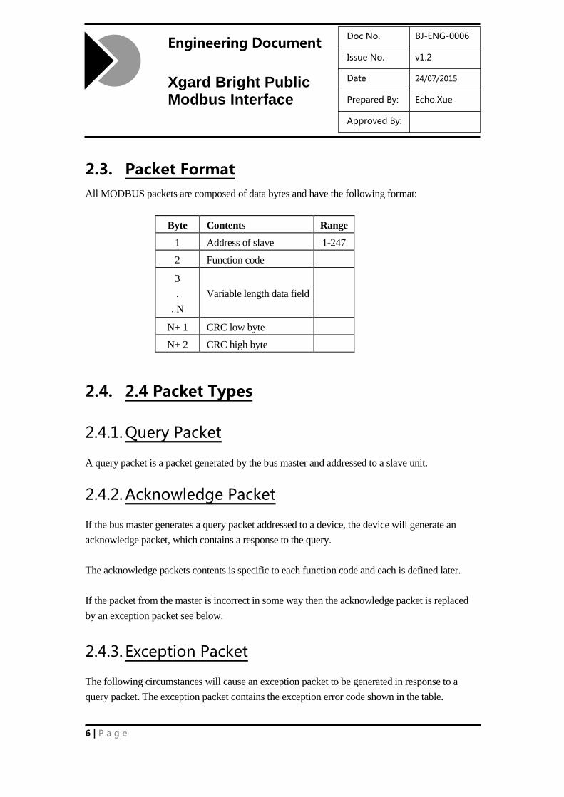
2.3. Packet Format
All MODBUS packets are composed of data bytes and have the following format:
Byte Contents Range
1 Address of slave 1-247
2 Function code
3
.
. N
Variable length data field
N+ 1 CRC low byte
N+ 2 CRC high byte
2.4. 2.4 Packet Types
2.4.1. Query Packet
A query packet is a packet generated by the bus master and addressed to a slave unit.
2.4.2. Acknowledge Packet
If the bus master generates a query packet addressed to a device, the device will generate an
acknowledge packet, which contains a response to the query.
The acknowledge packets contents is specific to each function code and each is defined later.
If the packet from the master is incorrect in some way then the acknowledge packet is replaced
by an exception packet see below.
2.4.3. Exception Packet
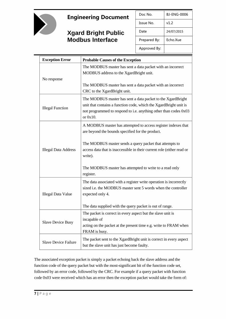
The following circumstances will cause an exception packet to be generated in response to a
query packet. The exception packet contains the exception error code shown in the table.
7 | P a g e
Engineering Document
Xgard Bright Public Modbus Interface
Doc No. BJ-ENG-0006
Issue No. v1.2
Date 24/07/2015
Prepared By: Echo.Xue
Approved By:
Exception Error
Code
Probable Causes of the Exception
No response
The MODBUS master has sent a data packet with an incorrect
MODBUS address to the XgardBright unit.
The MODBUS master has sent a data packet with an incorrect
CRC to the XgardBright unit.
Illegal Function
The MODBUS master has sent a data packet to the XgardBright
unit that contains a function code, which the XgardBright unit is
not programmed to respond to i.e. anything other than codes 0x03
or 0x10.
Illegal Data Address
A MODBUS master has attempted to access register indexes that
are beyond the bounds specified for the product.
The MODBUS master sends a query packet that attempts to
access data that is inaccessible in their current role (either read or
write).
The MODBUS master has attempted to write to a read only
register.
Illegal Data Value
The data associated with a register write operation is incorrectly
sized i.e. the MODBUS master sent 5 words when the controller
expected only 4.
The data supplied with the query packet is out of range.
Slave Device Busy
The packet is correct in every aspect but the slave unit is
incapable of
acting on the packet at the present time e.g. write to FRAM when
FRAM is busy.
Slave Device Failure The packet sent to the XgardBright unit is correct in every aspect
but the slave unit has just become faulty.
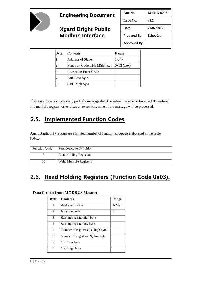
The associated exception packet is simply a packet echoing back the slave address and the
function code of the query packet but with the most-significant bit of the function code set,
followed by an error code, followed by the CRC. For example if a query packet with function
code 0x03 were received which has an error then the exception packet would take the form of:
8 | P a g e
Engineering Document
Xgard Bright Public Modbus Interface
Doc No. BJ-ENG-0006
Issue No. v1.2
Date 24/07/2015
Prepared By: Echo.Xue
Approved By:
Byte Contents Range
1 Address of Slave 1-247
2 Function Code with MSBit set. 0x83 (hex)
3 Exception Error Code
4 CRC low byte
5 CRC high byte
If an exception occurs for any part of a message then the entire message is discarded. Therefore,
if a multiple register write raises an exception, none of the message will be processed.
2.5. Implemented Function Codes
XgardBright only recognises a limited number of function codes, as elaborated in the table
below:
Function Code Function code Definition
3 Read Holding Registers
16 Write Multiple Registers
2.6. Read Holding Registers (Function Code 0x03).
Data format from MODBUS Master:
Byte Contents Range
1 Address of slave 1-247
2 Function code 3
3 Starting register high byte
4 Starting register low byte
5 Number of registers (N) high byte
6 Number of registers (N) low byte
7 CRC low byte
8 CRC high byte
9 | P a g e
Engineering Document
Xgard Bright Public Modbus Interface
Doc No. BJ-ENG-0006
Issue No. v1.2
Date 24/07/2015
Prepared By: Echo.Xue
Approved By:
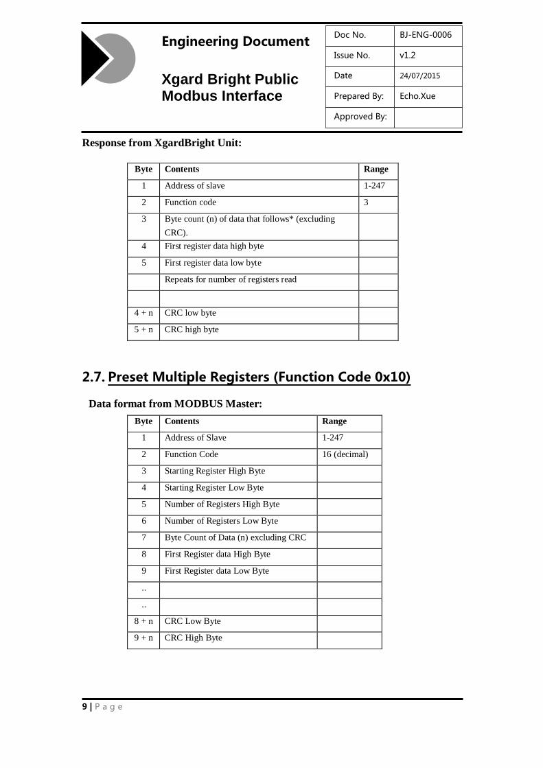
Response from XgardBright Unit:
Byte Contents Range
1 Address of slave 1-247
2 Function code 3
3 Byte count (n) of data that follows* (excluding
CRC).
4 First register data high byte
5 First register data low byte
Repeats for number of registers read
4 + n CRC low byte
5 + n CRC high byte
2.7. Preset Multiple Registers (Function Code 0x10)
Data format from MODBUS Master:
Byte Contents Range
1 Address of Slave 1-247
2 Function Code 16 (decimal)
3 Starting Register High Byte
4 Starting Register Low Byte
5 Number of Registers High Byte
6 Number of Registers Low Byte
7 Byte Count of Data (n) excluding CRC
8 First Register data High Byte
9 First Register data Low Byte
..
..
8 + n CRC Low Byte
9 + n CRC High Byte

10 | P a g e
Engineering Document
Xgard Bright Public Modbus Interface
Doc No. BJ-ENG-0006
Issue No. v1.2
Date 24/07/2015
Prepared By: Echo.Xue
Approved By:
Response from XgardBright Unit:
Byte Contents Range
1 Address of Slave 1-247
2 Function Code 16
3 Starting Register High Byte
4 Starting Register Low Byte
5 Number of Registers Preset
High Byte
6 Number of Registers Preset Low
Byte
7 CRC Low Byte
8 CRC High Byte
2.8. Data Timing
Standard MODBUS defines a silent interval of 3.5 characters times to delimit data packets.
However, a silent interval of 5mS is used to define the termination of a data packet – this assists
PC software in interpreting data packets.
The error condition described in [1] when there is a delay of 1.5 character times, but less than 3.5
character times between data, is not implemented – this can, apparently, cause problems with
legacy systems and PC timings.
On receipt of a message requiring a response, the instrument will pause for a guaranteed period
of at least 50mS before transmission will commence. Again, there may be timing problems on
PC systems if this restriction is not applied.
2.9. Modbus Data Types
The following data types may be used:
UINT16 Two bytes, unsigned integer (16 bits), one word long, most
significant byte first.
UINT32 Four bytes, unsigned integer (32 bits), 2 words, most significant
word first.
11 | P a g e
Engineering Document
Xgard Bright Public Modbus Interface
Doc No. BJ-ENG-0006
Issue No. v1.2
Date 24/07/2015
Prepared By: Echo.Xue
Approved By:
BIT32 Four bytes, each bit signifying a different status or code.
STRING nn Text string, nn characters long, packed 2 characters per word, of
length nn/2 words. Ordered with first character in high byte of first
word. Null padded in least significant byte of last word if needed.
FLOAT Floating point number, in IEEE-754 format.
ENUM Data enumeration. A UINT16 where each number (counting from
0) refers to an option from a list of possibilities. In the Register map
notes below, enumerations and their meanings are listed and may
be different for read and write operations on the same register.
2.10. Register Permissions
It is not necessarily possible to read or write every register in the modbus register map. The
permissions used in the modus map are:
R/W Read and write allowed. (Holding Registers)
R Read only. The information cannot be modified via Modbus (Input Registers).
2.11. Note on Message Processing
It is always guaranteed that registers in a message will be processed sequentially from message
start to message end. The XgardBright Host has a 256 byte modbus buffer. This buffer is large
enough to contain the largest valid modbus message.
2.12. Modbus Start-up Response
The XgardBright will respond to modbus as soon as it has reset. This allows for immediate
polling of identification registers
1 to 6 (inclusive).
The XgardBright will immediately enter an initialisation phase. During this phase other registers
in the map will be populated. Unpopulated data will read as 0. This phase can be detected by
reading register 100. It will return 65535 (or
12 | P a g e
Engineering Document
Xgard Bright Public Modbus Interface
Doc No. BJ-ENG-0006
Issue No. v1.2
Date 24/07/2015
Prepared By: Echo.Xue
Approved By:
0xffff in hexadecimal) whilst initialisation is in progress.
The next phase is warm-up. This is normally 30 seconds. During this phase the instrument will
be in start-up inhibit mode. During the warm-up phase the instrument cannot be gas zeroed or
calibrated (as the XgardBright is waiting for the gas readings to stabilise). Analogue output
adjustment (zero trim, span adjustment) is still possible during the warm-up phase. It is not
possible to control inhibit mode whilst the XgardBright is in start-up inhibit mode.
Once the warm-up phase is completed the instrument will operate normally.
For further information on inhibit see the note on inhibit in section 9, Analogue Output.
13 | P a g e
Engineering Document
Xgard Bright Public Modbus Interface
Doc No. BJ-ENG-0006
Issue No. v1.2
Date 24/07/2015
Prepared By: Echo.Xue
Approved By:
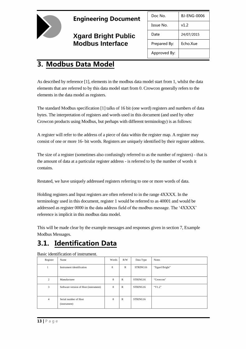
3. Modbus Data Model
As described by reference [1], elements in the modbus data model start from 1, whilst the data
elements that are referred to by this data model start from 0. Crowcon generally refers to the
elements in the data model as registers.
The standard Modbus specification [1] talks of 16 bit (one word) registers and numbers of data
bytes. The interpretation of registers and words used in this document (and used by other
Crowcon products using Modbus, but perhaps with different terminology) is as follows:
A register will refer to the address of a piece of data within the register map. A register may
consist of one or more 16- bit words. Registers are uniquely identified by their register address.
The size of a register (sometimes also confusingly referred to as the number of registers) - that is
the amount of data at a particular register address - is referred to by the number of words it
contains.
Restated, we have uniquely addressed registers referring to one or more words of data.
Holding registers and Input registers are often referred to in the range 4XXXX. In the
terminology used in this document, register 1 would be referred to as 40001 and would be
addressed as register 0000 in the data address field of the modbus message. The ‘4XXXX’
reference is implicit in this modbus data model.
This will be made clear by the example messages and responses given in section 7, Example
Modbus Messages.
3.1. Identification Data
Basic identification of instrument.
Register Name Words R/W Data Type Notes
1 Instrument identification 8 R STRING16 “Xgard Bright”
2 Manufacturer 8 R STRING16 “Crowcon"
3 Software version of Host (instrument) 8 R STRING16 “V1.2”
4 Serial number of Host
(instrument)
8 R STRING16
14 | P a g e
Engineering Document
Xgard Bright Public Modbus Interface
Doc No. BJ-ENG-0006
Issue No. v1.2
Date 24/07/2015
Prepared By: Echo.Xue
Approved By:
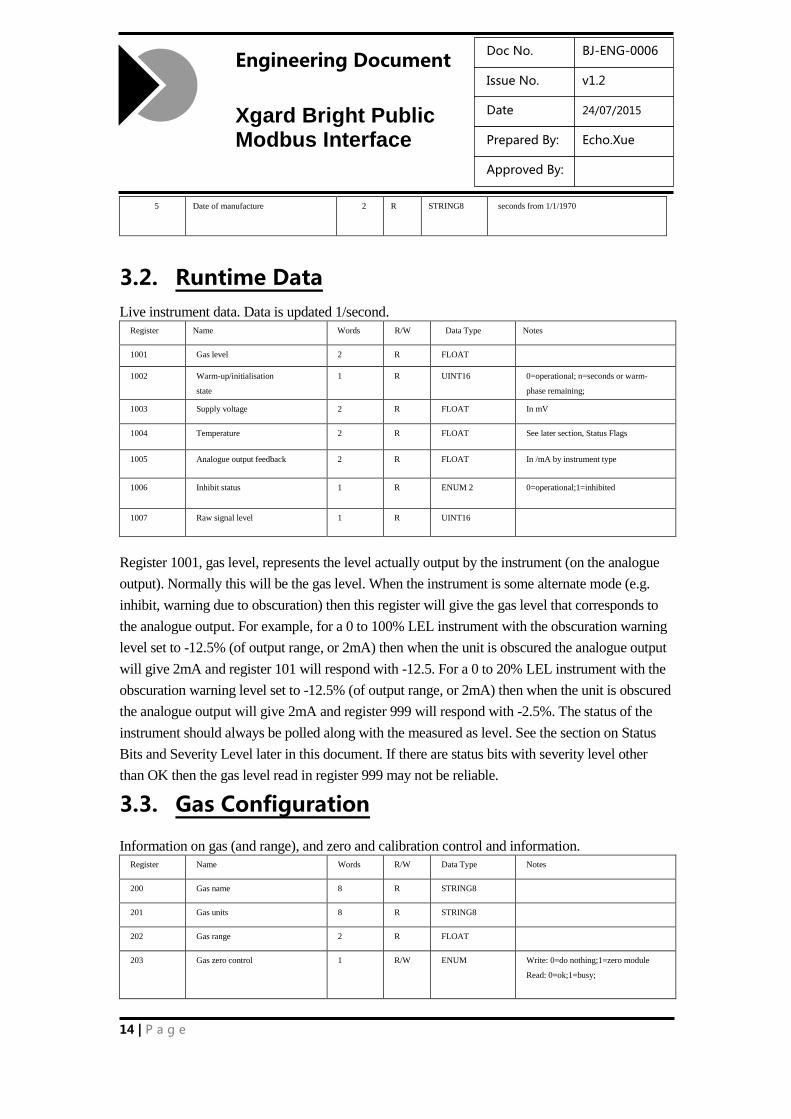
5 Date of manufacture 2 R STRING8 seconds from 1/1/1970
3.2. Runtime Data
Live instrument data. Data is updated 1/second.
Register Name Words R/W Data Type Notes
1001 Gas level 2 R FLOAT
1002 Warm-up/initialisation
state
1 R UINT16 0=operational; n=seconds or warm-
phase remaining;
1003 Supply voltage 2 R FLOAT In mV
1004 Temperature 2 R FLOAT See later section, Status Flags
1005 Analogue output feedback 2 R FLOAT In /mA by instrument type
1006 Inhibit status 1 R ENUM 2 0=operational;1=inhibited
1007 Raw signal level 1 R UINT16
Register 1001, gas level, represents the level actually output by the instrument (on the analogue
output). Normally this will be the gas level. When the instrument is some alternate mode (e.g.
inhibit, warning due to obscuration) then this register will give the gas level that corresponds to
the analogue output. For example, for a 0 to 100% LEL instrument with the obscuration warning
level set to -12.5% (of output range, or 2mA) then when the unit is obscured the analogue output
will give 2mA and register 101 will respond with -12.5. For a 0 to 20% LEL instrument with the
obscuration warning level set to -12.5% (of output range, or 2mA) then when the unit is obscured
the analogue output will give 2mA and register 999 will respond with -2.5%. The status of the
instrument should always be polled along with the measured as level. See the section on Status
Bits and Severity Level later in this document. If there are status bits with severity level other
than OK then the gas level read in register 999 may not be reliable.
3.3. Gas Configuration
Information on gas (and range), and zero and calibration control and information. Register Name Words R/W Data Type Notes
200 Gas name 8 R STRING8
201 Gas units 8 R STRING8
202 Gas range 2 R FLOAT
203 Gas zero control 1 R/W ENUM Write: 0=do nothing;1=zero module
Read: 0=ok;1=busy;
15 | P a g e
Engineering Document
Xgard Bright Public Modbus Interface
Doc No. BJ-ENG-0006
Issue No. v1.2
Date 24/07/2015
Prepared By: Echo.Xue
Approved By:
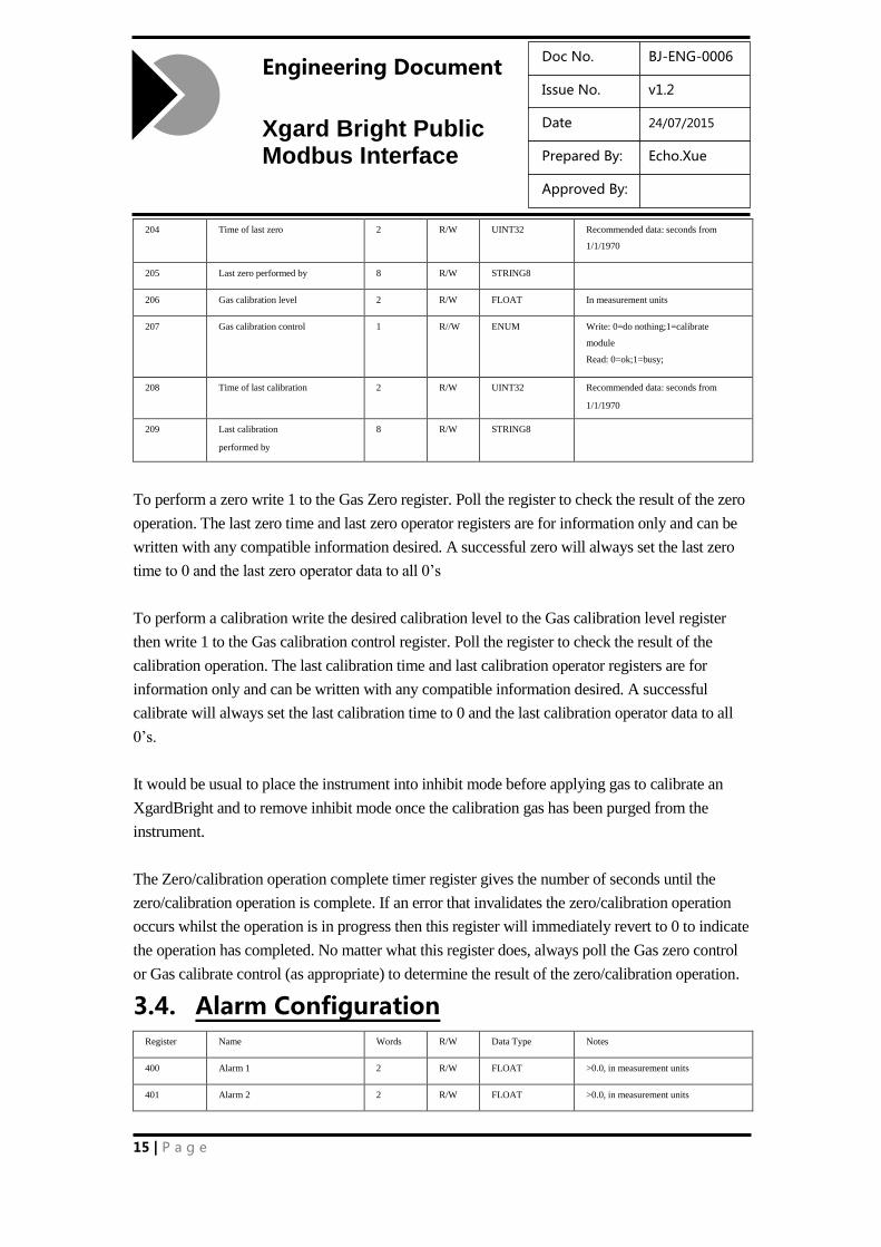
204 Time of last zero 2 R/W UINT32 Recommended data: seconds from
1/1/1970
205 Last zero performed by 8 R/W STRING8
206 Gas calibration level 2 R/W FLOAT In measurement units
207 Gas calibration control 1 R//W ENUM Write: 0=do nothing;1=calibrate
module
Read: 0=ok;1=busy;
208 Time of last calibration 2 R/W UINT32 Recommended data: seconds from
1/1/1970
209 Last calibration
performed by
8 R/W STRING8
To perform a zero write 1 to the Gas Zero register. Poll the register to check the result of the zero
operation. The last zero time and last zero operator registers are for information only and can be
written with any compatible information desired. A successful zero will always set the last zero
time to 0 and the last zero operator data to all 0’s
To perform a calibration write the desired calibration level to the Gas calibration level register
then write 1 to the Gas calibration control register. Poll the register to check the result of the
calibration operation. The last calibration time and last calibration operator registers are for
information only and can be written with any compatible information desired. A successful
calibrate will always set the last calibration time to 0 and the last calibration operator data to all
0’s.
It would be usual to place the instrument into inhibit mode before applying gas to calibrate an
XgardBright and to remove inhibit mode once the calibration gas has been purged from the
instrument.
The Zero/calibration operation complete timer register gives the number of seconds until the
zero/calibration operation is complete. If an error that invalidates the zero/calibration operation
occurs whilst the operation is in progress then this register will immediately revert to 0 to indicate
the operation has completed. No matter what this register does, always poll the Gas zero control
or Gas calibrate control (as appropriate) to determine the result of the zero/calibration operation.
3.4. Alarm Configuration Register Name Words R/W Data Type Notes
400 Alarm 1 2 R/W FLOAT >0.0, in measurement units
401 Alarm 2 2 R/W FLOAT >0.0, in measurement units
16 | P a g e
Engineering Document
Xgard Bright Public Modbus Interface
Doc No. BJ-ENG-0006
Issue No. v1.2
Date 24/07/2015
Prepared By: Echo.Xue
Approved By:
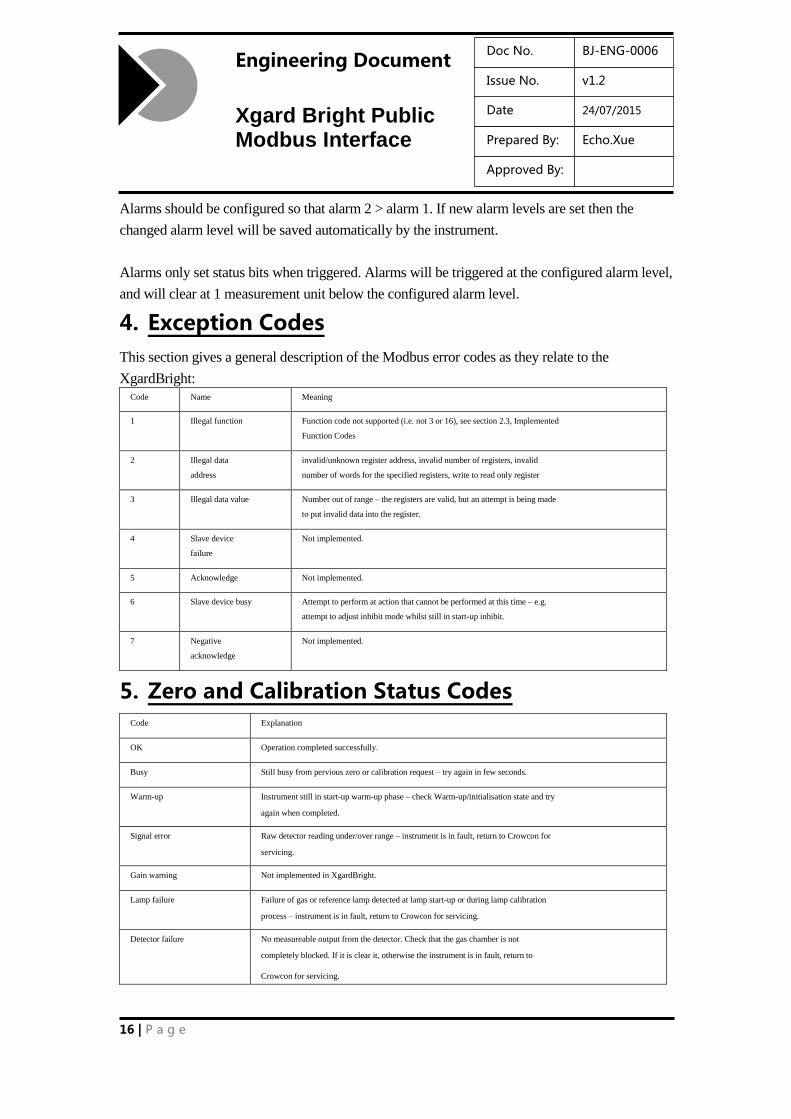
Alarms should be configured so that alarm 2 > alarm 1. If new alarm levels are set then the
changed alarm level will be saved automatically by the instrument.
Alarms only set status bits when triggered. Alarms will be triggered at the configured alarm level,
and will clear at 1 measurement unit below the configured alarm level.
4. Exception Codes
This section gives a general description of the Modbus error codes as they relate to the
XgardBright: Code Name Meaning
1 Illegal function Function code not supported (i.e. not 3 or 16), see section 2.3, Implemented
Function Codes
2 Illegal data
address
invalid/unknown register address, invalid number of registers, invalid
number of words for the specified registers, write to read only register
3 Illegal data value Number out of range – the registers are valid, but an attempt is being made
to put invalid data into the register.
4 Slave device
failure
Not implemented.
5 Acknowledge Not implemented.
6 Slave device busy Attempt to perform at action that cannot be performed at this time – e.g.
attempt to adjust inhibit mode whilst still in start-up inhibit.
7 Negative
acknowledge
Not implemented.
5. Zero and Calibration Status Codes Code Explanation
OK Operation completed successfully.
Busy Still busy from pervious zero or calibration request – try again in few seconds.
Warm-up Instrument still in start-up warm-up phase – check Warm-up/initialisation state and try
again when completed.
Signal error Raw detector reading under/over range – instrument is in fault, return to Crowcon for
servicing.
Gain warning Not implemented in XgardBright.
Lamp failure Failure of gas or reference lamp detected at lamp start-up or during lamp calibration
process – instrument is in fault, return to Crowcon for servicing.
Detector failure No measureable output from the detector. Check that the gas chamber is not
completely blocked. If it is clear it, otherwise the instrument is in fault, return to
Crowcon for servicing.
17 | P a g e
Engineering Document
Xgard Bright Public Modbus Interface
Doc No. BJ-ENG-0006
Issue No. v1.2
Date 24/07/2015
Prepared By: Echo.Xue
Approved By:
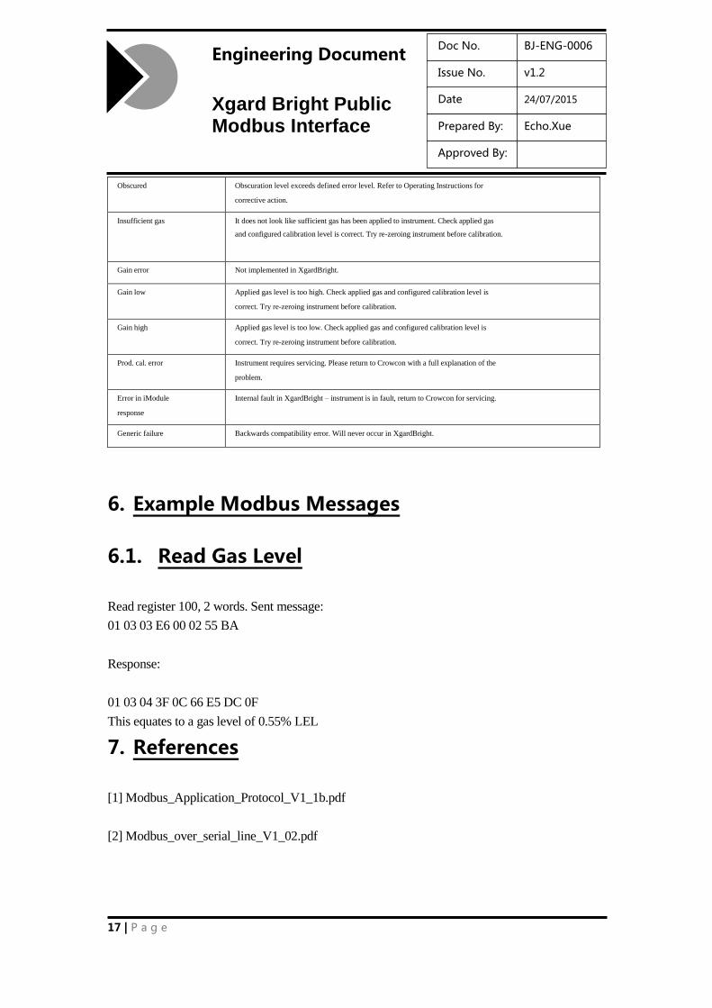
Obscured Obscuration level exceeds defined error level. Refer to Operating Instructions for
corrective action.
Insufficient gas It does not look like sufficient gas has been applied to instrument. Check applied gas
and configured calibration level is correct. Try re-zeroing instrument before calibration.
Gain error Not implemented in XgardBright.
Gain low Applied gas level is too high. Check applied gas and configured calibration level is
correct. Try re-zeroing instrument before calibration.
Gain high Applied gas level is too low. Check applied gas and configured calibration level is
correct. Try re-zeroing instrument before calibration.
Prod. cal. error Instrument requires servicing. Please return to Crowcon with a full explanation of the
problem.
Error in iModule
response
Internal fault in XgardBright – instrument is in fault, return to Crowcon for servicing.
Generic failure Backwards compatibility error. Will never occur in XgardBright.
6. Example Modbus Messages
6.1. Read Gas Level
Read register 100, 2 words. Sent message:
01 03 03 E6 00 02 55 BA
Response:
01 03 04 3F 0C 66 E5 DC 0F
This equates to a gas level of 0.55% LEL
7. References
[1] Modbus_Application_Protocol_V1_1b.pdf
[2] Modbus_over_serial_line_V1_02.pdf


![DPU2000/1500R/2000R MODBUS / MODBUS PLUS … · DPU2000/1500R/2000R Modbus/Modbus Plus Automation Guide i DPU2000/1500R/2000R MODBUS / MODBUS PLUS ... [Catalog 587XXX00-XXX0 or 587XXXX6-XXX4]](https://static.fdocuments.in/doc/165x107/5acb9eac7f8b9a73128bdc42/dpu20001500r2000r-modbus-modbus-plus-modbusmodbus-plus-automation-guide.jpg)