SMA Modbus® Interface
22
Technical Information SMA Modbus® Interface SMA DATA MANAGER EDMx-Modbus-TI-en-15 | Version 1.5 ENGLISH
Transcript of SMA Modbus® Interface
Technical Information
SMA Modbus® InterfaceSMA DATA MANAGER
EDMx-Modbus-TI-en-15 | Version 1.5ENGLISH
Legal Provisions SMA Solar Technology AG
Technical InformationEDMx-Modbus-TI-en-152
Legal ProvisionsThe information contained in these documents is the property of SMA Solar Technology AG. Nopart of this document may be reproduced, stored in a retrieval system, or transmitted, in any form orby any means, be it electronic, mechanical, photographic, magnetic or otherwise, without the priorwritten permission of SMA Solar Technology AG. Internal reproduction used solely for the purposeof product evaluation or other proper use is allowed and does not require prior approval.SMA Solar Technology AG makes no representations or warranties, express or implied, withrespect to this documentation or any of the equipment and/or software it may describe, including(with no limitation) any implied warranties of utility, merchantability, or fitness for any particularpurpose. All such representations or warranties are expressly disclaimed. Neither SMA SolarTechnology AG nor its distributors or dealers shall be liable for any indirect, incidental, orconsequential damages under any circumstances.The exclusion of implied warranties may not apply in all cases under some statutes, and thus theabove exclusion may not apply.Specifications are subject to change without notice. Every attempt has been made to make thisdocument complete, accurate and up-to-date. Readers are cautioned, however, that productimprovements and field usage experience may cause SMA Solar Technology AG to make changesto these specifications without advance notice or per contract provisions. SMA Solar TechnologyAG shall not be responsible for any damages, including indirect, incidental or consequentialdamages, caused by reliance on the material presented, including, but not limited to, omissions,typographical errors, arithmetical errors or listing errors in the content material.SMA Solar Technology AG reserves the right to modify the implementation of communicationinterfaces and protocols at any time without notifying the user. It is the user’s responsibility todetermine whether the downloaded content is up to date and to comply with it. SMA SolarTechnology AG shall not be held liable for any damage as well as any assumption ofconsequential costs for customer systems by SMA Solar Technology AG that may result from theuser’s failure to do so.
Software licensesYou will find the software licenses for the installed software modules (open source) on the Internetat www.SMA-Solar.com.
TrademarksAll trademarks are recognized, even if not explicitly identified as such. Missing designations do notmean that a product or brand is not a registered trademark.
SMA Solar Technology AGSonnenallee 134266 NiestetalGermanyPhone +49 561 9522-0Fax +49 561 9522 100www.SMA.deE-mail: [email protected]

Legal ProvisionsSMA Solar Technology AG
Technical Information EDMx-Modbus-TI-en-15 3
Status: 11/10/2021Copyright © 2021 SMA Solar Technology AG. All rights reserved.

Table of Contents SMA Solar Technology AG
Technical InformationEDMx-Modbus-TI-en-154
Table of Contents1 Information on this Document................................................. 5
1.1 Validity ........................................................................................................................ 51.2 Target Group.............................................................................................................. 51.3 Content and Structure of this Document ................................................................... 51.4 Levels of warning messages ...................................................................................... 51.5 Symbols in the Document .......................................................................................... 61.6 Typographical Elements in the Document ................................................................ 6
2 Safety ........................................................................................ 72.1 Intended Use .............................................................................................................. 72.2 IMPORTANT SAFETY INSTRUCTIONS.................................................................... 7
3 Product Overview .................................................................... 93.1 Modbus Protocol........................................................................................................ 93.2 SMA Modbus Profile ................................................................................................. 93.3 System Topology........................................................................................................ 93.4 Addressing and Data Transmission........................................................................... 9
3.4.1 Unit IDs.................................................................................................... 93.4.2 Register Address, Register Width and Data Block ............................... 93.4.3 Data Transmission................................................................................... 103.4.4 Reading and Writing of Data ................................................................ 103.4.5 SMA Data Types and NaN Values ...................................................... 113.4.6 SMA Data Formats................................................................................. 113.4.7 SMA Firmware Data Formats ................................................................ 12
3.5 Modbus Ports ............................................................................................................. 133.6 Data Processing and Time Behavior ......................................................................... 133.7 Frequently Used Number Codes .............................................................................. 14
4 Assignment Tables ................................................................... 164.1 Information on Assignment Tables ............................................................................ 164.2 Unit ID = 1 (Communication Product) ...................................................................... 164.3 Unit ID = 2 (System) .................................................................................................. 16
5 Contact ...................................................................................... 21
1 Information on this DocumentSMA Solar Technology AG
Technical Information EDMx-Modbus-TI-en-15 5
1 Information on this Document
1.1 ValidityThis document is valid for:
• EDML-10 (SMA Data Manager L)• EDMM-10 (SMA Data Manager M)• EDMM-US-10 (SMA Data Manager M)• EDMM-10.A (SMA Data Manager M Lite)
1.2 Target GroupThe tasks described in this document must only be performed by qualified persons. Qualifiedpersons must have the following skills:
• Detailed knowledge of the grid management services• Knowledge of IP-based network protocols• Knowledge of the Modbus specifications• Training in the installation and configuration of IT systems• Knowledge of and compliance with this document and all safety information
1.3 Content and Structure of this DocumentThis document does not contain any information on the Modbus registers provided by SMAproducts. Furthermore, no information on the firmware version to be installed on the respectiveSMA product is included. Information on firmware versions and device-specific Modbus registers ofSMA products can be found on our product pages or Modbus page at www.SMA-Solar.com.This document does not contain any information on software which can communicate with theModbus interface (see the software manufacturer's manual).This document contains a general description of the Modbus interface integrated in SMA products.This document does not contain any information related to parameters for grid managementservices (system control objects). For more information on these parameters, contact the SMAService.Illustrations in this document are reduced to the essential information and may deviate from the realproduct.
1.4 Levels of warning messagesThe following levels of warning messages may occur when handling the product.
DANGERIndicates a hazardous situation which, if not avoided, will result in death or serious injury.
WARNINGIndicates a hazardous situation which, if not avoided, could result in death or serious injury.
1 Information on this Document SMA Solar Technology AG
Technical InformationEDMx-Modbus-TI-en-156
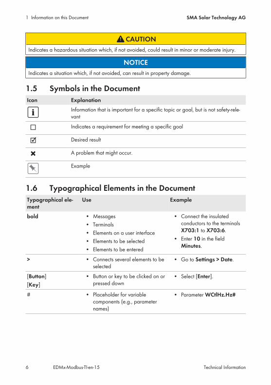
CAUTIONIndicates a hazardous situation which, if not avoided, could result in minor or moderate injury.
NOTICEIndicates a situation which, if not avoided, can result in property damage.
1.5 Symbols in the DocumentIcon Explanation
Information that is important for a specific topic or goal, but is not safety-rele-vant
☐ Indicates a requirement for meeting a specific goal
☑ Desired result
✖ A problem that might occur.
Example
1.6 Typographical Elements in the DocumentTypographical ele-ment
Use Example
bold • Messages• Terminals• Elements on a user interface• Elements to be selected• Elements to be entered
• Connect the insulatedconductors to the terminalsX703:1 to X703:6.
• Enter 10 in the fieldMinutes.
> • Connects several elements to beselected
• Go to Settings > Date.
[Button][Key]
• Button or key to be clicked on orpressed down
• Select [Enter].
# • Placeholder for variablecomponents (e.g., parameternames)
• Parameter WCtlHz.Hz#
2 SafetySMA Solar Technology AG
Technical Information EDMx-Modbus-TI-en-15 7
2 Safety
2.1 Intended UseThe Modbus interface of the supported SMA products is designed for industrial use and has thefollowing tasks:
• Remote control of grid management services• Remote-controlled querying of measured values• Remote-controlled changing of parameters• Interface for direct marketing
The Modbus interface can only be used via the Modbus TCP protocol.All components must remain within their permitted operating ranges and their installationrequirements at all times.Use SMA products only in accordance with the information provided in the encloseddocumentation and with the locally applicable laws, regulations, standards and directives. Anyother application may cause personal injury or property damage.Alterations to the SMA products, e.g., changes or modifications, are only permitted with the expresswritten permission of SMA Solar Technology AG. Unauthorized alterations will void guarantee andwarranty claims and in most cases terminate the operating license. SMA Solar Technology AGshall not be held liable for any damage caused by such changes.Any use of the product other than that described in the Intended Use section does not qualify asappropriate.The enclosed documentation is an integral part of this product. Keep the documentation in aconvenient, dry place for future reference and observe all instructions contained therein.This document does not replace any regional, state, provincial, federal or national laws, regulationsor standards that apply to the installation, electrical safety and use of the product. SMA SolarTechnology AG assumes no responsibility for the compliance or non-compliance with such laws orcodes in connection with the installation of the product.
2.2 IMPORTANT SAFETY INSTRUCTIONSKeep the manual for future reference.This section contains safety information that must be observed at all times when working.The product has been designed and tested in accordance with international safety requirements. Aswith all electrical or electronical devices, there are residual risks despite careful construction. Toprevent personal injury and property damage and to ensure long-term operation of the product,read this section carefully and observe all safety information at all times.
2 Safety SMA Solar Technology AG
Technical InformationEDMx-Modbus-TI-en-158
NOTICEDamage of SMA products due to cyclical changing of parametersThe parameters of SMA products that can be changed with writable Modbus registers (RW) areintended for long-term storage of device settings. Cyclical changing of these parameters leads todestruction of the flash memory of the SMA products.Parameters for grid management services to control and limit the nominal PV system power arean exception. Such parameters (system control objects) may be changed cyclically.
• Do not change device parameters cyclically.• Use the parameters for grid management services for the automated remote control of the
PV system.
NOTICEManipulation of system data in networksYou can connect the supported SMA products to the Internet. When connected to the Internet,there is a risk that unauthorized users can access and manipulate the data of your system.
• Set up a firewall.• Close unnecessary network ports.• If absolutely necessary, only enable remote access via a virtual private network (VPN).• Do not use the port forwarding feature. This also applies to the used Modbus ports.• Disconnect system components from other network components (network segmentation).
Access to data points after activating the Modbus interfaceThe read-only access to data points is possible after activating the Modbus interface. Thewrite-only access to all designated data points is possible. All parameter changes are shownon the user interface of the SMA product.
• Ensure that the Modbus interface is still active after resetting the SMA product to defaultsettings.
3 Product OverviewSMA Solar Technology AG
Technical Information EDMx-Modbus-TI-en-15 9
3 Product Overview
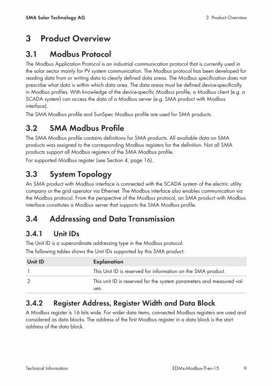
3.1 Modbus ProtocolThe Modbus Application Protocol is an industrial communication protocol that is currently used inthe solar sector mainly for PV system communication. The Modbus protocol has been developed forreading data from or writing data to clearly defined data areas. The Modbus specification does notprescribe what data is within which data area. The data areas must be defined device-specificallyin Modbus profiles. With knowledge of the device-specific Modbus profile, a Modbus client (e.g. aSCADA system) can access the data of a Modbus server (e.g. SMA product with Modbusinterface).The SMA Modbus profile and SunSpec Modbus profile are used for SMA products.
3.2 SMA Modbus ProfileThe SMA Modbus profile contains definitions for SMA products. All available data on SMAproducts was assigned to the corresponding Modbus registers for the definition. Not all SMAproducts support all Modbus registers of the SMA Modbus profile.For supported Modbus register (see Section 4, page 16).
3.3 System TopologyAn SMA product with Modbus interface is connected with the SCADA system of the electric utilitycompany or the grid operator via Ethernet. The Modbus interface also enables communication viathe Modbus protocol. From the perspective of the Modbus protocol, an SMA product with Modbusinterface constitutes a Modbus server that supports the SMA Modbus profile.
3.4 Addressing and Data Transmission
3.4.1 Unit IDsThe Unit ID is a superordinate addressing type in the Modbus protocol.The following tables shows the Unit IDs supported by this SMA product.
Unit ID Explanation1 This Unit ID is reserved for information on the SMA product.
2 This unit ID is reserved for the system parameters and measured val-ues.
3.4.2 Register Address, Register Width and Data BlockA Modbus register is 16 bits wide. For wider data items, connected Modbus registers are used andconsidered as data blocks. The address of the first Modbus register in a data block is the startaddress of the data block.
3 Product Overview SMA Solar Technology AG
Technical InformationEDMx-Modbus-TI-en-1510
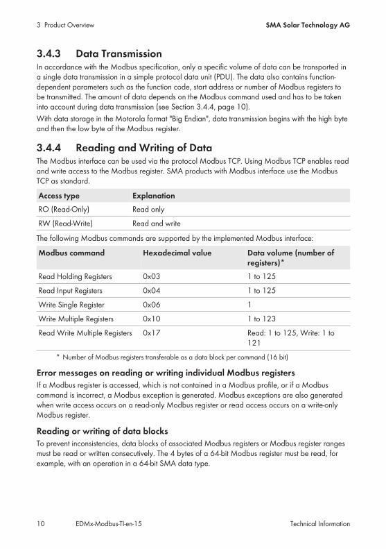
3.4.3 Data TransmissionIn accordance with the Modbus specification, only a specific volume of data can be transported ina single data transmission in a simple protocol data unit (PDU). The data also contains function-dependent parameters such as the function code, start address or number of Modbus registers tobe transmitted. The amount of data depends on the Modbus command used and has to be takeninto account during data transmission (see Section 3.4.4, page 10).With data storage in the Motorola format "Big Endian", data transmission begins with the high byteand then the low byte of the Modbus register.
3.4.4 Reading and Writing of DataThe Modbus interface can be used via the protocol Modbus TCP. Using Modbus TCP enables readand write access to the Modbus register. SMA products with Modbus interface use the ModbusTCP as standard.
Access type ExplanationRO (Read-Only) Read only
RW (Read-Write) Read and write
The following Modbus commands are supported by the implemented Modbus interface:
Modbus command Hexadecimal value Data volume (number ofregisters)*
Read Holding Registers 0x03 1 to 125
Read Input Registers 0x04 1 to 125
Write Single Register 0x06 1
Write Multiple Registers 0x10 1 to 123
Read Write Multiple Registers 0x17 Read: 1 to 125, Write: 1 to121
* Number of Modbus registers transferable as a data block per command (16 bit)
Error messages on reading or writing individual Modbus registersIf a Modbus register is accessed, which is not contained in a Modbus profile, or if a Modbuscommand is incorrect, a Modbus exception is generated. Modbus exceptions are also generatedwhen write access occurs on a read-only Modbus register or read access occurs on a write-onlyModbus register.
Reading or writing of data blocksTo prevent inconsistencies, data blocks of associated Modbus registers or Modbus register rangesmust be read or written consecutively. The 4 bytes of a 64-bit Modbus register must be read, forexample, with an operation in a 64-bit SMA data type.

3 Product OverviewSMA Solar Technology AG
Technical Information EDMx-Modbus-TI-en-15 11
Reading multiple Modbus registers as a data blockIf a data block is read and if at least one register defined in the Modbus profile can be determinedin its data range, an answer is returned. If this data block also contains Modbus registers that arenot defined in the Modbus profile, NaN is used for the query values in each case. If none of theModbus registers are defined in the data range of a data block in the Modbus profile, the query isinvalid and a Modbus exception is generated.
Error message on writing multiple Modbus registers as a data blockIf multiple registers are written in the data block (Modbus command 0x10 and 0x17) and an erroroccurs when writing, the process continues with the next register in the data block. If some data isdependent on other data, or if some data is mutually exclusive, the data is only processed if theentire data block is valid. Otherwise the entire data block is discarded. In the event of an error, aModbus exception will be generated.
Modbus exceptionsFor Modbus exceptions, see "Modbus Application Protocol Specification" at http://www.modbus.org/specs.php.
3.4.5 SMA Data Types and NaN ValuesThe following table shows the data types used in the SMA Modbus profile and compares these topossible NaN values. The SMA data types are listed in the assignment tables in the Type column.The SMA data types describe the data widths of the assigned values:
Type Explanation NaN valueS16 A signed word (16-bit). 0x8000
S32 A signed double word (32-bit). 0x8000 0000
STR32 32 byte data field, in UTF8 format. ZERO
U16 A word (16-bit). 0xFFFF
U32 A double word (32-bit). 0xFFFF FFFF
U32 For status values, only the lower 24 bits of a double word(32-bit) are used.
0xFFFF FD
U64 A quadruple word (64-bit). 0xFFFF FFFF FFFFFFFF
3.4.6 SMA Data FormatsThe following SMA data formats describe how SMA data is to be interpreted. The data formats areused, for example, for the display of data or for its further processing. The SMA data formats arelisted in the Format column of the assignment tables.
Format ExplanationDuration Time in seconds, in minutes or in hours, depending on the Modbus
register

3 Product Overview SMA Solar Technology AG
Technical InformationEDMx-Modbus-TI-en-1512
Format ExplanationENUMorTAGLIST
Coded numerical values. The breakdown of the possible codes canbe found directly under the designation of the Modbus register inthe assignment tables.
FIX0 Decimal number, commercially rounded, without decimal place.
FIX1 Decimal number, commercially rounded, one decimal place.
FIX2 Decimal number, commercially rounded, two decimal places.
FIX3 Decimal number, commercially rounded, three decimal places.
FIX4 Decimal number, commercially rounded, four decimal places.
FUNCTION_SEC The date saved in the Modbus register will be transmitted in theevent of a change to a function and starts this. After execution of thefunction, no status value is set. A security question must be executedin the client software prior to execution of the function.
FW Firmware version
HW Hardware version (e.g. 24)
IP4 4-byte IP address (IPv4) of the form XXX.XXX.XXX.XXX.
RAW Text or number. A RAW number has no decimal places and no thou-sand or other separation indicators.
Outline Purchase Agreement Revision number of the form 2.3.4.5.
TEMP Temperature values are stored in special Modbus registers in de-grees Celsius (°C), in degrees Fahrenheit (°F), or in Kelvin K. Thevalues are commercially rounded, with one decimal place.
TM UTC time, in seconds
UTF8 Data in UTF8 format.
DT Date/time (Transmission in seconds since 1970-01-01)
3.4.7 SMA Firmware Data FormatsFour values are extracted from the delivered double word (DWORD) within the correspondingModbus register. The values "Major" and "Minor" are contained BCD-coded in bytes 1 and 2. Byte3 contains the "Build" value (not BCD-coded). Byte 4 contains the "Release Type" value accordingto the following table:
Release type Release-type coding Explanation0 N No revision number
1 E Experimental release
2 A Alpha release
3 B Beta release
3 Product OverviewSMA Solar Technology AG
Technical Information EDMx-Modbus-TI-en-15 13
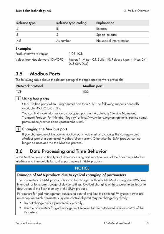
Release type Release-type coding Explanation4 R Release
5 S Special release
> 5 As number No special interpretation
Example:Product firmware version: 1.05.10.RValues from double word (DWORD): Major: 1, Minor: 05, Build: 10, Release type: 4 (Hex: 0x1
0x5 0xA 0x4)
3.5 Modbus PortsThe following table shows the default setting of the supported network protocols:
Network protocol Modbus portTCP 502
Using free portsOnly use free ports when using another port than 502. The following range is generallyavailable: 49152 to 65535.You can find more information on occupied ports in the database "Service Name andTransport Protocol Port Number Registry" at http://www.iana.org/assignments/service-names-port-numbers/service-names-port-numbers.xml.
Changing the Modbus portIf you change one of the communication ports, you must also change the correspondingModbus port of a connected Modbus/client system. Otherwise the SMA product can nolonger be accessed via the Modbus protocol.
3.6 Data Processing and Time BehaviorIn this Section, you can find typical data-processing and reaction times of the Speedwire Modbusinterface and time details for saving parameters in SMA products.
NOTICEDamage of SMA products due to cyclical changing of parametersThe parameters of SMA products that can be changed with writable Modbus registers (RW) areintended for long-term storage of device settings. Cyclical changing of these parameters leads todestruction of the flash memory of the SMA products.Parameters for grid management services to control and limit the nominal PV system power arean exception. Such parameters (system control objects) may be changed cyclically.
• Do not change device parameters cyclically.• Use the parameters for grid management services for the automated remote control of the
PV system.
3 Product Overview SMA Solar Technology AG
Technical InformationEDMx-Modbus-TI-en-1514
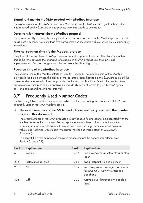
Signal runtime via the SMA product with Modbus interfaceThe signal runtime of the SMA product with Modbus is usually 150 ms. The signal runtime is thetime required by the SMA product to process incoming Modbus commands.
Data transfer interval via the Modbus protocolFor system stability reasons, the time period between data transfers via the Modbus protocol shouldbe at least 1 second. No more than five parameters and measured values should be simultaneouslytransmitted.
Physical reaction time via the Modbus protocolThe physical reaction time of SMA products is normally approx. 1 second. The physical reactiontime is the time between the changing of setpoints in a SMA product until their physicalimplementation. Such a change would be, for example, changing cos φ.
Reaction time of the Modbus interfaceThe reaction time of the Modbus interface is up to 1 second. The reaction time of the Modbusinterface is the time between the arrival of the parameter specifications in the SMA product until thecorresponding measured values are provided to the Modbus interface. Due to this reaction time,parameter specifications can be displayed via a Modbus/client system (e.g., a SCADA system)only at a corresponding or larger interval.
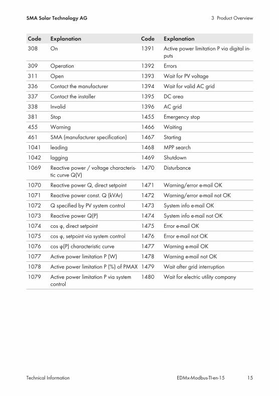
3.7 Frequently Used Number CodesThe following table contains number codes which, as function coding in data format ENUM, arefrequently used in the SMA Modbus profile.
The event numbers of the SMA products are not decrypted with the numbercodes in this document.The event numbers of the SMA products are device-specific and cannot be decrypted with thenumber codes in this document. To decrypt the event numbers of low or medium-powerinverters, you require additional information such as operating parameters and measuredvalues (see Technical Description "Measured Values and Parameters" at www.SMA-Solar.com).To decrypt the event numbers of central inverters, contact the Service department (seeSection 5, page 21).
Code Explanation Code Explanation51 Closed 1387 Reactive power Q, setpoint via analog
input
276 Instantaneous value 1388 cos φ, setpoint via analog input
295 MPP 1389 Reactive power / voltage characteris-tic curve Q(U) with hysteresis anddeadband
303 Off 1390 Active power limitation P via analoginput
3 Product OverviewSMA Solar Technology AG
Technical Information EDMx-Modbus-TI-en-15 15
Code Explanation Code Explanation308 On 1391 Active power limitation P via digital in-
puts
309 Operation 1392 Errors
311 Open 1393 Wait for PV voltage
336 Contact the manufacturer 1394 Wait for valid AC grid
337 Contact the installer 1395 DC area
338 Invalid 1396 AC grid
381 Stop 1455 Emergency stop
455 Warning 1466 Waiting
461 SMA (manufacturer specification) 1467 Starting
1041 leading 1468 MPP search
1042 lagging 1469 Shutdown
1069 Reactive power / voltage characteris-tic curve Q(V)
1470 Disturbance
1070 Reactive power Q, direct setpoint 1471 Warning/error e-mail OK
1071 Reactive power const. Q (kVAr) 1472 Warning/error e-mail not OK
1072 Q specified by PV system control 1473 System info e-mail OK
1073 Reactive power Q(P) 1474 System info e-mail not OK
1074 cos φ, direct setpoint 1475 Error e-mail OK
1075 cos φ, setpoint via system control 1476 Error e-mail not OK
1076 cos φ(P) characteristic curve 1477 Warning e-mail OK
1077 Active power limitation P (W) 1478 Warning e-mail not OK
1078 Active power limitation P (%) of PMAX 1479 Wait after grid interruption
1079 Active power limitation P via systemcontrol
1480 Wait for electric utility company

4 Assignment Tables SMA Solar Technology AG
Technical InformationEDMx-Modbus-TI-en-1516
4 Assignment Tables
4.1 Information on Assignment TablesThe following subsections are sorted by unit ID. Each contains a table of the Modbus registerswhich can be accessed using this unit ID. The tables present the following information:
Information ExplanationADR Decimal Modbus register
Description/number codes Short description of the Modbus register and the number codesused
CNT Number of assigned Modbus registers
Type Data type
Format Data format of the saved value
Access Access type
4.2 Unit ID = 1 (Communication Product)The following table lists the parameters provided by the communication product and measuredvalues that can be accessed at Unit ID = 1:
ADR Description/number codes CNT Type Format Access30001 Version number of the SMA profile 2 U32 RAW RO
30003 SUSyID (Device ID) 2 U32 RAW RO
30005 Serial number 2 U32 RAW RO
30007 Modbus data change: counter value will in-crease if data in the Profile has changed(overflow).
2 U32 RAW RO
30051 Device class:• 8128 = Communication products
2 U32 ENUM RO
30193 UTC system time (s) 2 U32 DT RO
4.3 Unit ID = 2 (System)In the following table, you can find the PV system parameters that you can access using unit ID = 2.The system parameters represent measured values and parameters of the communication productand also system devices that are connected via the Modbus protocol. Parameters such as timesettings are transferred by the communication product to the devices of the system and there,depending on the device type, processed further. Measured values such as energy meter valuesare queried by the devices and made available as accumulated values:
ADR Description/number codes CNT Type Format Access30193 UTC system time (s) 2 V32 DT RO

4 Assignment TablesSMA Solar Technology AG
Technical Information EDMx-Modbus-TI-en-15 17
ADR Description/number codes CNT Type Format Access30201 Current state of health; 5-minute value; de-
vice status2 V32 ENUM RO
30233 Accumulated connected power of the PV in-verter (W)
2 V32 FIX0 RO
30513 Total energy fed in on all line conductors(Wh)
4 V64 FIX0 RO
30517 Energy fed in on the current day on all lineconductors, in Wh
4 V64 FIX0 RO
30775 Current PV feed-in active power on all lineconductors (W)
2 S32 FIX0 RO
30805 Reactive power on all line conductors (VAr) 2 S32 FIX0 RO
30845 * Current battery state of charge (SOC in re-lation to present capacity of the battery), in%
2 V32 FIX0 RO
31235 Power limitation via digital input (%) 2 V32 FIX2 RO
31237 Setpoint of active power limitation P viaanalog input, in %
2 V32 FIX2 RO
31239 PV power limitation via communication (%) 2 V32 FIX2 RO
31241 PV power limitation via communication fordirect marketing (%)
2 V32 FIX2 RO
31243 Maximum active power setpoint, in % 2 V32 FIX2 RO
31245 Internal PV power limitation (%) 2 V32 FIX2 RO
31249 Active power of system at PCC (W) 2 S32 FIX0 RO
31251 Reactive power of system at PCC (VAr) 2 S32 FIX0 RO
31393 * Current battery charge, in W 2 V32 FIX0 RO
31395 * Current battery discharge, in W 2 V32 FIX0 RO
31397 * Battery charge, in Wh 4 V64 FIX0 RO
31401 * Battery discharge, in Wh 4 V64 FIX0 RO
31503 * Feed-in of power into grid: Line conductorL1 at PCC, in W
2 S32 FIX0 RO
31505 * Feed-in of power into grid: Line conductorL2 at PCC, in W
2 S32 FIX0 RO
31507 * Feed-in of power into grid: Line conductorL3 at PCC, in W
2 S32 FIX0 RO

4 Assignment Tables SMA Solar Technology AG
Technical InformationEDMx-Modbus-TI-en-1518
ADR Description/number codes CNT Type Format Access31509 * Feed-in of reactive power into grid: Line
conductor L1 at PCC, in VAr2 S32 FIX0 RO
31511 * Feed-in of reactive power into grid: Lineconductor L2 at PCC, in VAr
2 S32 FIX0 RO
31513 * Feed-in of reactive power into grid: Lineconductor L3 at PCC, in VAr
2 S32 FIX0 RO
31515 * System voltage: Line conductor L1 - L2 atPCC, in V
2 V32 FIX2 RO
31517 * System voltage: Line conductor L2 - L3 atPCC, in V
2 V32 FIX2 RO
31519 * System voltage: Line conductor L3 - L1 atPCC, in V
2 V32 FIX2 RO
31521 * Mean value of grid voltage L-N at PCC, inV
2 V32 FIX2 RO
31523 * Mean value of grid voltage L-L at PCC, in V 2 V32 FIX2 RO
31525 * Displacement power factor at PCC 2 S32 FIX2 RO
31527 * Grid frequency at PCC, in Hz 2 V32 FIX2 RO
31529 * System voltage: Line conductor L1 at PCC,in V
2 V32 FIX2 RO
31531 * System voltage: Line conductor L2 at PCC,in V
2 V32 FIX2 RO
31533 * System voltage: Line conductor L3 at PCC,in V
2 V32 FIX2 RO
31535 * System current: Line conductor L1 at PCC 2 S32 FIX3 RO
31537 * System current: Line conductor L2 at PCC 2 S32 FIX3 RO
31539 * System current: Line conductor L3 at PCC 2 S32 FIX3 RO
31545 * Power value of the generating system whenall generating units are in operation, in W
2 V32 FIX0 RO
32185 Internal PV reactive power limitation (%) 2 S32 FIX2 RO
32187 * Available underexcited reactive power, inVAr
2 S32 FIX0 RO
**
32189 * Available overexcited reactive power, inVAr
2 S32 FIX0 RO
**
32191 * Theoretically available power output, in W 2 V32 FIX2 RO
4 Assignment TablesSMA Solar Technology AG
Technical Information EDMx-Modbus-TI-en-15 19
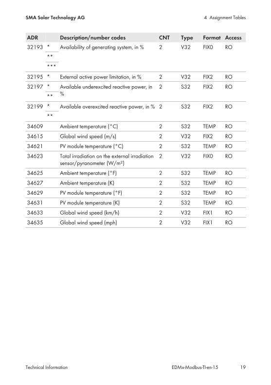
ADR Description/number codes CNT Type Format Access32193 * Availability of generating system, in % 2 V32 FIX0 RO
**
***
32195 * External active power limitation, in % 2 V32 FIX2 RO
32197 * Available underexcited reactive power, in%
2 S32 FIX2 RO
**
32199 * Available overexcited reactive power, in % 2 S32 FIX2 RO
**
34609 Ambient temperature (°C) 2 S32 TEMP RO
34615 Global wind speed (m/s) 2 V32 FIX2 RO
34621 PV module temperature (°C) 2 S32 TEMP RO
34623 Total irradiation on the external irradiationsensor/pyranometer (W/m²)
2 V32 FIX0 RO
34625 Ambient temperature (°F) 2 S32 TEMP RO
34627 Ambient temperature (K) 2 S32 TEMP RO
34629 PV module temperature (°F) 2 S32 TEMP RO
34631 PV module temperature (K) 2 S32 TEMP RO
34633 Global wind speed (km/h) 2 V32 FIX1 RO
34635 Global wind speed (mph) 2 V32 FIX1 RO

4 Assignment Tables SMA Solar Technology AG
Technical InformationEDMx-Modbus-TI-en-1520
ADR Description/number codes CNT Type Format Access34653 Digital input group 1, coded as status:
• 311 = Open• 2055 = DI1• 2056 = DI1 DI2• 2057 = DI1 DI2 DI3• 2058 = DI1 DI2 DI3 DI4• 2059 = DI1 DI2 DI4• 2060 = DI1 DI3• 2061 = DI1 DI3 DI4• 2062 = DI1 DI4• 2063 = DI2• 2064 = DI2 DI3• 2065 = DI2 DI3 DI4• 2066 = DI2 DI4• 2067 = DI3• 2068 = DI3 DI4• 2069 = DI4
2 V32 ENUM RO
40018 Quick shut-down of the inverters• 311 = Standby• 1467 = start• 1749 = full stop (AC and DC sides)
2 V32 ENUM RW/WO
40493 Direct marketer:Active power setpoint P, in % of the maxi-mum active power (PMAX) of the PV plant.Value range:
• -100% to -1% = load• 0% = no active power• < 0% to 100% = generator
1 S16 FIX2 RW/WO
41167 Manually set active power limit for the en-tire system (%)
2 V32 FIX2 RW/WO
* Does not apply to EDMM-10.A. Valid values are only sent if a Modbus profile is available. Otherwisea NaN value is sent.
** Sensors for module temperature, ambient temperature and irradiation must be included in the systemand configured in the SMA Data Manager.
*** Compliant with parameter Pbinst/Pinst according to VDE AR-N 4110 (Table C2). PBinst: Sum of therated active power of all generating units in operation. Pinst: Sum of the rated active powers of allgenerating units within a generating system. Determined only for inverters with the status "Inoperation" (OPERATION_OPSTT).

5 ContactSMA Solar Technology AG
Technical Information EDMx-Modbus-TI-en-15 21
5 ContactYou can find your country's contact information at:
https://go.sma.de/service

www.SMA-Solar.com