MODAL PROPERTIES AND SEISMIC RESPONSE OF EXISTING …
16
ECCOMAS Congress 2016 VII European Congress on Computational Methods in Applied Sciences and Engineering M. Papadrakakis, V. Papadopoulos, G. Stefanou, V. Plevris (eds.) Crete Island, Greece, 5–10 June 2016 MODAL PROPERTIES AND SEISMIC RESPONSE OF EXISTING BUILDING RETROFITTED BY EXTERNAL BRACINGS WITH VISCOUS DAMPERS Laura Gioiella 1 , Enrico Tubaldi 2 , Fabrizio Gara 1 and Andrea Dall'Asta 3 1 DICEA – Università Politecnica delle Marche via Brecce Bianche, 60121 Ancona, Italy l.gioiella,[email protected] 2 Department of Civil Engineering – Imperial College Skempton Building, South Kensington Campus, Imperial College London, SW7 2AZ, UK [email protected] 3 Scuola di Architettura e Design – Università di Camerino Viale delle Rimembranze, 63100 Ascoli Piceno, Italy [email protected] Keywords: Passive Seismic Protection, Linear Viscous Dampers, External Seismic Retro- fit, Dissipative Towers. Abstract. This paper deals with the seismic protection of existing buildings using external viscous damper systems to increase the energy dissipation capacity. Dampers and bracings can be arranged in very different configurations and the possible solutions can be grouped into different categories, depending on the specific kinematic behavior. The study analyzes a recent solution called "dissipative tower", which, for the dampers activation, exploits the rocking motion of a stiff steel truss hinged at the foundation level. A state space formulation of the dynamic problem is presented in general terms and some issues concerning the influ- ence of the bracing properties on the behavior of a case study consisting of a building cou- pled with a dissipative tower are investigated. The results presented concern both the influence of the external dissipative bracings on the most important modal properties of the system, and the global effect on the seismic response, evaluated via the modal decomposition method. It is shown that the addition of the towers yields a regularization of the drift demand along the building height, but it can also induce significant changes in the distribution of in- ternal actions in the existing frame. Moreover, the contribution of higher order modes can be important for the internal actions evaluation, while it is negligible for the displacement esti- mation. The results obtained by considering the coupled system are compared with the corre- sponding results obtained by considering two limit cases: the bare frame, and the frame equipped with an infinitely stiff dissipative tower.
Transcript of MODAL PROPERTIES AND SEISMIC RESPONSE OF EXISTING …

ECCOMAS Congress 2016
VII European Congress on Computational Methods in Applied Sciences and Engineering
M. Papadrakakis, V. Papadopoulos, G. Stefanou, V. Plevris (eds.) Crete Island, Greece, 5–10 June 2016
MODAL PROPERTIES AND SEISMIC RESPONSE OF EXISTING
BUILDING RETROFITTED BY EXTERNAL BRACINGS WITH
VISCOUS DAMPERS
Laura Gioiella1, Enrico Tubaldi
2, Fabrizio Gara
1 and Andrea Dall'Asta
3
1 DICEA – Università Politecnica delle Marche
via Brecce Bianche, 60121 Ancona, Italy
l.gioiella,[email protected]
2 Department of Civil Engineering – Imperial College
Skempton Building, South Kensington Campus, Imperial College London, SW7 2AZ, UK
3 Scuola di Architettura e Design – Università di Camerino
Viale delle Rimembranze, 63100 Ascoli Piceno, Italy
Keywords: Passive Seismic Protection, Linear Viscous Dampers, External Seismic Retro-
fit, Dissipative Towers.
Abstract. This paper deals with the seismic protection of existing buildings using external
viscous damper systems to increase the energy dissipation capacity. Dampers and bracings
can be arranged in very different configurations and the possible solutions can be grouped
into different categories, depending on the specific kinematic behavior. The study analyzes a
recent solution called "dissipative tower", which, for the dampers activation, exploits the
rocking motion of a stiff steel truss hinged at the foundation level. A state space formulation
of the dynamic problem is presented in general terms and some issues concerning the influ-
ence of the bracing properties on the behavior of a case study consisting of a building cou-
pled with a dissipative tower are investigated. The results presented concern both the
influence of the external dissipative bracings on the most important modal properties of the
system, and the global effect on the seismic response, evaluated via the modal decomposition
method. It is shown that the addition of the towers yields a regularization of the drift demand
along the building height, but it can also induce significant changes in the distribution of in-
ternal actions in the existing frame. Moreover, the contribution of higher order modes can be
important for the internal actions evaluation, while it is negligible for the displacement esti-
mation. The results obtained by considering the coupled system are compared with the corre-
sponding results obtained by considering two limit cases: the bare frame, and the frame
equipped with an infinitely stiff dissipative tower.

Laura Gioiella, Enrico Tubaldi, Fabrizio Gara and Andrea Dall'Asta
1 INTRODUCTION
Passive control systems have proven to be very efficient solutions for new constructions
and for seismic retrofitting of existing structures [1-4]. Viscous dampers are traditionally in-
stalled within a building frame in either diagonal or chevron brace configurations connecting
adjacent storeys and there are many studies concerning both the dynamic properties of the
damped system and the methods for the design [e.g., 5-10]. However, this type of damping
system may present some disadvantages, particularly when employed for retrofitting existing
buildings. Usually, the addition of dissipative diagonal in existing frames provides an incre-
ment of axial forces in the columns and this may lead to premature local failures [11]. Fur-
thermore, there may be some feasibility limits on the strengthening of the existing foundations
at the base of the bracing system. Also, the indirect costs related to the interruption of the
building utilization during execution of the retrofit can be very demanding, in particular for
strategic buildings, such as hospitals or schools.
These problems can be efficiently resolved by considering external damper configurations,
i.e., by placing the dissipative bracings and the relevant foundations outside the building
frame. External dampers and bracing components can be arranged in very different configura-
tions and the possible solutions can be grouped into three main categories, characterized by
substantially different kinematic behaviors, but all permitting the control of both the total
amount of the dissipated energy and the frame deformation at the various storeys. A possible
solution can be obtained by placing the dampers horizontally at the storey level, between the
frame and an external stiff structure [12]. This way, the links are activated by the floor abso-
lute displacements. A similar configuration can be obtained by placing the dampers between
adjacent buildings, though this solution is efficient if the two buildings have strongly different
dynamic properties [13-16]. An alternative solution can be obtained by coupling the frame
with an external shear deformable bracing structure. The new and existing structures are con-
nected at the storey level and the dissipative devices are activated by the relative displace-
ments between adjacent floors, as in the more traditional case of bracings placed within the
existing structure [3].
Recently, some applications have been developed by proposing a new configuration ex-
ploiting the rocking motion of a stiff brace hinged at the foundation level [17, 18]. In this con-
figuration, known as "dissipative tower" (Figure 1) [19], the dampers are activated by the base
rotation of the tower.
This work focuses on the coupling between an existing frame and a rocking dissipative
configuration shown in Figure 1; the purpose is the investigation of the modal properties and
the seismic response of the coupled system by means of a problem formulation presented in
general terms. The dynamic behavior and seismic performance of the system is compared
against that of two other limit cases, the first one being the bare building, the second the
building coupled with an infinitely stiff dissipative tower.
Figure 1: Dissipative Tower.

Laura Gioiella, Enrico Tubaldi, Fabrizio Gara and Andrea Dall'Asta
2 PROBLEM FORMULATION
In the first part of this section, the equation of motion and the state variables of the consid-
ered problem are presented by assuming that both the building and the external damping sys-
tem exhibit a linear response. The limit case of stiff tower is also presented and the balance
equations of the reduced single-degree-of-freedom (SDOF) system are obtained by introduc-
ing a constraint in the structure motion.
2.1 Equation of motion
The equations of motion for the system can be expressed as follows:
tatttg
MpKuuCuM (1)
where lRt u , is the vector of nodal displacements, the dot (∙) denotes time-derivative;
lRp is the load distribution vector, l denotes the total number of degrees-of-freedom, and
ag(t) is the external scalar loading function describing the seismic base acceleration. The time
invariant matrices M , K , C describe the mass, stiffness and damping operators llRR ;
they result from the sum of the contribution due to the existing frame and the one coming
from the external dissipative bracing system. The damping contribution of the frame and of
the dissipative system are denoted respectively as C F and C D. Generally, the external bracing
system notably influences the stiffness and damping operators while it contributes only mar-
ginally to the mass operator. The displacement vector tu collects both the displacements
required for the description of the frame response and the displacements involved in the brac-
ing deformations.
In order to study the dynamic response of the system it is useful to separate the displace-
ments associated with the masses, and thus involving inertial forces, from the displacements
describing the internal degrees of freedom, related to stiffness and damping forces only. Ac-
cordingly, the total displacement vector tu can be split into the active components collected
in the vector mRt x and the other components n
Rt y ( nml ). The matrices describ-
ing the linear operators and the distribution vector can be consequently partitioned as follows
g
xxx
yyyx
xyxx
yyyx
xyxxxxa
000
0
00
0 pM
y
x
KK
KK
y
x
CC
CC
y
xM
(2)
As usual, only the masses related to the horizontal floor displacements are considered in
order to reduce the dimension of the dynamic problem and to simplify the interpretation of the
results.
The distribution of the damping in the structure and, in particular, the location of the con-
centrated dampers of the external bracings, leads to a non-classically damped system. For its
solution it is convenient to formulate the problem by introducing the vector tt xv and
the state vector tz collecting the displacements and the velocities of the active displace-
ments and the displacements of the internal nodes:
t
t
t
t
y
v
x
z (3)
Eqn. (1) can be reduced to a first-order state space form:

Laura Gioiella, Enrico Tubaldi, Fabrizio Gara and Andrea Dall'Asta
tattg
pAzz~
(4)
where:
yyyyyxyyyxyy
yyyyxyxyxxyxyyxyxxxxyxyyxyxxxx
KCCCKC
KCCKMCCCCMKCCKM
0I0
A
111
111111
(5)
Vector p~ is defined as:
0
0
~ 1pMp
xx (6)
2.2 Free vibrations and modal properties
The free vibration problem can be solved by assuming a solution of the form tet
φz ,
where φ, are a eigenvalue-eigenvector pair of A , such that:
φA φ (7)
Complex eigenvalue has the following form:
2
001
iiiiii (8)
and contains information regarding both the damping ratio ξi and the corresponding
undamped circular frequency ω0i of the i-th mode. These information can be extrapolated as
follows:
iii
ii
/Re
0
(9)
Known the modal properties, the problem solution can be obtained as a linear combination
of the single mode contributions. Let Λ be the diagonal matrix containing the complex ei-
genvalues and nm
221
,...,, φφφΦ the complex eigenmatrix containing the eigenvectors,
such that the orthogonality property AΦΦΛ1
holds.
2.3 Seismic response via modal decomposition method
The motion can be obtained as a linear combination of modes:
tt Φqz (10)
where tq is a vector collecting the modal coordinates. The orthogonality property leads to
the diagonal problem:
tattg
γΛqq (11)
where ii
pΦ~1
is the i-th (complex-valued) modal participation factor.
Introducing the normalized complex modal response vector ts such that: tstqiii
,
the problem can be written in a normalized form:

Laura Gioiella, Enrico Tubaldi, Fabrizio Gara and Andrea Dall'Asta
tattg
IΛss (12)
Assuming that the system is initially at rest, the solution can be obtained by the Duhamel
integral:
dattg
t
)(
0
hs (13)
where the components t
i
ieth
are the solutions related to an impulsive unitary input.
2.4 Generalized SDOF system approximation
The dissipative tower consists of an external bracings system that activates the dampers lo-
cated at its base through its rocking motion. In the case of an infinitely stiff tower all the de-
grees of freedom of the system (active displacements of the frame and displacements involved
in the bracing deformations) are governed by the base rotation . This means that the dis-
placement vector tu , shown in eqn. 1, can be expressed as
Lu t (14)
in which L is a vector collecting the heights of the frame. The D'Alembert Principle for the
problem at hand can be expressed by introducing a virtual velocity field ˆˆ L , in which ̂
is an arbitrary base rotation. Eqn. 1 can be rewritten for any time instant t as
gbDFb
a ˆˆˆˆˆ pMKuCuCuM t (15)
where the matrices M b, K b,C F describe the mass, stiffness and damping of the frame and
where C D is the dissipative contribution of the dampers located at the tower base. This way,
the tower influences only the damping operator and the shape of the virtual displacement field.
Eqn. 15 can be rewritten as
gDF
amkccm*~~~~
(16)
where LLM b
m~ , LLC
FFc~ , LLC
DDc~ , LLK
bk~
, LpM b
m*
are the scalar
parameters describing the properties of the system reduced to a SDOF, and denotes the sca-
lar product. By solving Eqn. 15, the time-history of the base rotation is known, and the vector
of nodal displacements of the MDOF system is determined by considering Eqn. (14).
3 CASE STUDY
3.1 Case study description
The application of the proposed approach is illustrated by considering a r.c. frame structure,
with limited ductility, typical of many buildings designed during the 80s in Italy without any
specific seismic detailing. Along the longitudinal direction, the structure consists of two ex-
ternal frames with 6 spans and a central one with 7 spans (Figure 2). The building has 5 sto-
reys plus the roof.
The presented results concern three configurations, the bare existing frame (As is), the r,c,
frame coupled with dissipative tower hinged at the foundation level and equipped with linear
viscous dampers located at the base (Retrofit), and the r.c. frame coupled with an infinitely
stiff dissipative tower (Stiff).

Laura Gioiella, Enrico Tubaldi, Fabrizio Gara and Andrea Dall'Asta
Figure 2: Planar view and longitudinal section of the bare building.
First, the previously described formulation is employed to investigate the influence of the
external bracing properties on the overall dynamic properties of the coupled system, such as
the modal displacement profile, the relevant internal action distribution and the modal damp-
ing ratios. Successively, the global effect of the retrofit on the seismic response is evaluated
by solving the seismic problem with the modal decomposition method for the first two con-
figurations (As is and Retrofit) and with a direct integration method for the last one (Stiff).
The dynamic system is described by considering only the motion along the longitudinal di-
rection. The floors are assumed to be rigid in the horizontal plane and the masses are concen-
trated at the storey levels so that the vector of active degrees of freedom x collects the five
storey motions only.
3.2 Modal properties of the undamped system
The bracing system influences both the stiffness and the damping properties of the coupled
system, while its contribution to the masses is negligible. It is useful to separately analyze the
variations on stiffness and damping and, for this purpose, the case of the added tower without
dampers is considered separately from the case of the tower with dampers.
Table 1 reports, for the five modes of the bare building (As is), the vibration periods, the
undamped natural frequencies and the participant mass ratios, defined as
iiii
M ψM ψψMp 2* where
iψ are the eigenvectors of the undamped system.
Ti [s] ω02 Mi
* ΣMi
*
1.021 6.18 0.787 0.787
0.300 21.03 0.117 0.904
0.153 41.26 0.052 0.956
0.097 65.51 0.03 0.985
0.074 86.05 0.015 1
Table 1: Modal analysis results - As is configuration.
The modal analysis results of the coupled system in the Retrofit configuration are summa-
rized in Table 2, where it can be observed that the first two vibration modes involve the 95%
of the total mass and the second period reduces to about half the value obtained with the As is
configuration. The third case, i.e. the existing frame coupled with an infinitely stiff tower
(Stiff), is characterized by one vibration mode only (T=0.925 s) as it behaves like a SDOF sys-
tem governed by the tower rocking motion.

Laura Gioiella, Enrico Tubaldi, Fabrizio Gara and Andrea Dall'Asta
Ti [s] ω02 Mi
* ΣMi
*
0.964 6.52 0.806 0.806
0.147 42.84 0.138 0.945
0.073 86.24 0.035 0.980
0.051 124.17 0.015 0.995
0.041 151.63 0.005 1
Table 2: Modal analysis results – Retrofit configuration.
Figure 3 reports and compares the values of the interstorey drifts along the building height
corresponding to the first three modes of vibration for the As is and the Retrofit configurations.
It can be observed that the addition of the towers yields a regularization of the drift demands
along the building height, even though a higher value of the drift is required at the first level.
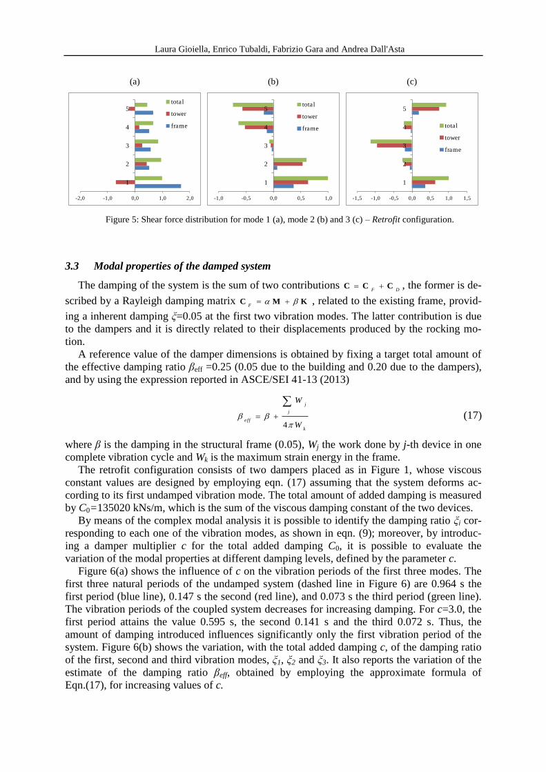
Figure 4 reports the distributions of the total shear forces in the As is and Retrofit cases for
the first three modes, whereas Figure 5 shows, for the Retrofit configuration only, the storey
shear demand for the building and the tower. It is worth to note that the shear contributions of
the existing frame and the towers could have different signs at some levels and, for the con-
sidered case, the first mode shear forces acting on the existing frame is higher than the total
shear force at the first level.
(a) (b) (c)
0,0 0,1 0,2 0,3
1
2
3
4
5Retrofit
As is
-1,0 -0,5 0,0 0,5 1,0
1
2
3
4
5Retrofit
As is
-2,0 -1,0 0,0 1,0 2,0
1
2
3
4
5
Retrofit
As is
Figure 3: Interstorey drifts along the building height for mode 1 (a), mode 2 (b) and 3 (c).
(a) (b) (c)
0 0,2 0,4 0,6 0,8 1
1
2
3
4
5Retrofit
As is
-1 -0,5 0 0,5 1
1
2
3
4
5Retrofit
As is
-1,5 -1 -0,5 0 0,5 1 1,5
1
2
3
4
5
Retrofit
As is
Figure 4: Total shear force comparison for mode 1 (a), mode 2 (b) and 3 (c).
Laura Gioiella, Enrico Tubaldi, Fabrizio Gara and Andrea Dall'Asta
(a) (b) (c)
-2,0 -1,0 0,0 1,0 2,0
1
2
3
4
5total
tower
frame
-1,0 -0,5 0,0 0,5 1,0
1
2
3
4
5total
tower
frame
-1,5 -1,0 -0,5 0,0 0,5 1,0 1,5
1
2
3
4
5
total
tower
frame
Figure 5: Shear force distribution for mode 1 (a), mode 2 (b) and 3 (c) – Retrofit configuration.
3.3 Modal properties of the damped system
The damping of the system is the sum of two contributions DF
CCC , the former is de-
scribed by a Rayleigh damping matrix F
C M K , related to the existing frame, provid-
ing a inherent damping ξ=0.05 at the first two vibration modes. The latter contribution is due
to the dampers and it is directly related to their displacements produced by the rocking mo-
tion.
A reference value of the damper dimensions is obtained by fixing a target total amount of
the effective damping ratio βeff =0.25 (0.05 due to the building and 0.20 due to the dampers),
and by using the expression reported in ASCE/SEI 41-13 (2013)
4
j
j
e ff
k
W
W
(17)
where β is the damping in the structural frame (0.05), Wj the work done by j-th device in one
complete vibration cycle and Wk is the maximum strain energy in the frame.
The retrofit configuration consists of two dampers placed as in Figure 1, whose viscous
constant values are designed by employing eqn. (17) assuming that the system deforms ac-
cording to its first undamped vibration mode. The total amount of added damping is measured
by C0=135020 kNs/m, which is the sum of the viscous damping constant of the two devices.
By means of the complex modal analysis it is possible to identify the damping ratio ξi cor-
responding to each one of the vibration modes, as shown in eqn. (9); moreover, by introduc-
ing a damper multiplier c for the total added damping C0, it is possible to evaluate the
variation of the modal properties at different damping levels, defined by the parameter c.
Figure 6(a) shows the influence of c on the vibration periods of the first three modes. The
first three natural periods of the undamped system (dashed line in Figure 6) are 0.964 s the
first period (blue line), 0.147 s the second (red line), and 0.073 s the third period (green line).
The vibration periods of the coupled system decreases for increasing damping. For c=3.0, the
first period attains the value 0.595 s, the second 0.141 s and the third 0.072 s. Thus, the
amount of damping introduced influences significantly only the first vibration period of the
system. Figure 6(b) shows the variation, with the total added damping c, of the damping ratio
of the first, second and third vibration modes, ξ1, ξ2 and ξ3. It also reports the variation of the
estimate of the damping ratio βeff, obtained by employing the approximate formula of
Eqn.(17), for increasing values of c.

Laura Gioiella, Enrico Tubaldi, Fabrizio Gara and Andrea Dall'Asta
(a) (b)
0,00
0,20
0,40
0,60
0,80
1,00
1,20
0 0,5 1 1,5 2 2,5 3
T [s]
c
T1 T2 T3
T1u T2u T3u
0,00
0,10
0,20
0,30
0,40
0,50
0,60
0,70
0 0,5 1 1,5 2 2,5 3
ξi
c
ξ1 ξ2
ξ3 βeff
Figure 6: First three period trends (a) and first three modes damping trends (b) for increasing damping levels.
The first modal damping ratio ξ1 is well approximated by the design formula of Eqn. (17)
for values up to 0.50 (c=2.25); for increasing values beyond this limit the amount of the ef-
fective damping decreases. As already observed for the periods, the influence of the damper
dimensions on the second and third mode is negligible; the damping ratio varies in the range
0.050-0.067 with a maximum 0.074 when c=1.25 for the second mode, while for the third
mode the range is 0.091-0.094 with a maximum value of 0.097 when c=0.75.
Due to the fact that all the dampers are concentrated at the tower base the system is notably
non-classical damped and the extent of non-classical damping is synthetically quantified by
the coupling index ρ (Claret e Venancio-Filho 1991), expressed as:
jjii
ij
2
max (i, j=1,2,…,m) ji (18)
where jixxij
ψψC is the modal damping matrix component, xx
C and m are defined in
section 2.1 and i
ψ are the eigenvectors of the undamped system. The index assumes the value
0 for classical damped systems and it spans the range [0,1] in the case of non-classical damp-
ing. Figure 7(a) shows the coupling index trend for increasing damping levels, while Figure
7(b) shows the values of ρ obtained for the damping target value c=1. In the latter case the
maximum value of ρ is equal to 0.35 and corresponds to the coupling among the first and the
second mode.
(a) (b)
0,00
0,20
0,40
0,60
0,80
1,00
0 0,5 1 1,5 2 2,5 3
ρ
c
ρ
0.35
0.14 0.08
0.02 0.01
0.35 0.14
0.08
0.02
0.01
0
0
0
0.01
0.01
0
0
000
1 2 3 4 5
mode
mo
de
5
4
3
2
11
1
1
1
1
Figure 7: ρ-index: (a) trend for increasing damping levels; (b) values for the fifth modes of the system (c=1).

Laura Gioiella, Enrico Tubaldi, Fabrizio Gara and Andrea Dall'Asta
3.4 Seismic response
This section reports some results concerning the response of the three system configura-
tions to a seismic input. The seismic action is determined by assuming the building located in
Camerino (MC, Italy), with soil category C and topographical one T1, according to Italian
code [20]. Seven artificial earthquakes, generated in accordance with Italian Standards, are
considered. The results reported concern the most interesting parameters, i.e., the displace-
ments, interstorey drifts, shear action distribution and the absolute accelerations; the values of
these parameters reported below are the mean of the maximum values obtained for each of the
seven time-histories analyses. The results related to the coupled systems (Retrofit and Stiff
configurations) correspond to a total added damping multiplier c =1.
Table 3 reports the floor displacements and the interstorey drifts for the three configura-
tions analyzed. The maximum top displacement, normalized with respect to that of the bare
frame, is 54% for the Retrofit case and 58% for the Stiff case. Figure 8(a) and (b) show the
distribution along the height of the building displacements xi and interstorey drifts i, for
i=1,2,..,5. The reported values are normalized by dividing them by the corresponding values
obtained at the 5th level in the Stiff configuration.
level As is Retrofit Stiff
xi [m] i [m] xi [m] i [m] xi [m] i [m]
1 0.013 0.013 0.008 0.008 0.009 0.009
2 0.040 0.028 0.019 0.011 0.018 0.009
3 0.068 0.029 0.029 0.011 0.027 0.009
4 0.092 0.026 0.040 0.011 0.036 0.009
5 0.109 0.019 0.050 0.010 0.046 0.009
Table 3: Floor displacements and drifts results
a) b)
0,0 1,0 2,0 3,0
1
2
3
4
5
Stiff
Retrofit
As is
0 1 2 3 4
1
2
3
4
5Stiff
Retrofit
As is
Figure 8: Displacements (a) and interstorey drifts (b) distributions for the three configurations.
It is noteworthy that the coupling with an infinitely stiff tower leads to a linear distribution
of the displacements along the height. Moreover, the displacement demand at the first level is
higher in the Stiff case than in the Retrofit case, while an opposite trend is observed at the top.
This means that the regularization of the frame displacement distribution is achieved with the
tower interacting with opposite forces at the base and at the top of the frame.

Laura Gioiella, Enrico Tubaldi, Fabrizio Gara and Andrea Dall'Asta
Having employed the complex mode superposition approach to solve the seismic problem,
the contribution of the higher vibration modes to the response can be estimated by comparing
the full response accounting for all the modes to the response obtained by considering the
contribution of the first mode only. Table 4 reports the displacement response for the As is
and the Retrofit case. Figure 9 comparises the displacement responses of the As is and Retrofit
cases. In both the cases, the first mode contribution nearly controls the total response, while
the effect of higher order modes is negligible.
level As is Retrofit
xfull [m] x1 [m] xfull [m] x1 [m]
1 0.0129 0.0121 0.0080 0.0080
2 0.0405 0.0392 0.0188 0.0187
3 0.0684 0.0680 0.0295 0.0294
4 0.0918 0.0920 0.0399 0.0399
5 0.1092 0.1081 0.0497 0.0496
Table 4: Floor displacements and drifts results.
(a) (b)
0,00 0,50 1,00
1
2
3
4
5
As is_first
mode
As is_full
response
0,00 0,50 1,00
1
2
3
4
5
Retrofit_first
mode
Retrofit_full
response
Figure 9: Contribution of the first mode to the full response of the (a) As is and (b) Retrofit cases.
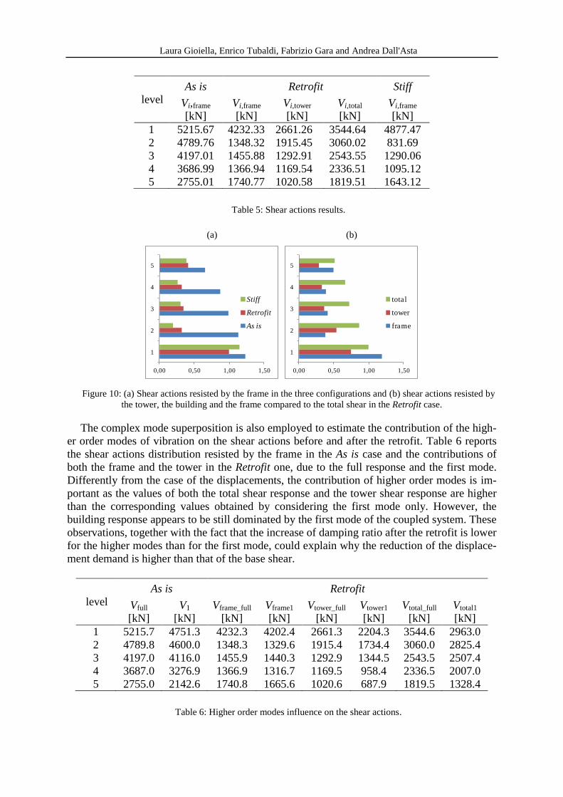
Table 5 reports the shear actions resisted by the frame in the three configurations; for the
Retrofit case the shear actions resisted by the tower and the total shear actions are also report-
ed. It is noteworthy that the maximum shear for the tower and the frame may not occur at the
same instant of time for all the records considered. As already discussed for the displacements,
also the global shear demand decreases, but in a less significant way. The relative reduction of
the maximum base shear acting on the frame, with respect to the bare frame, is nearly 19% for
the Retrofit case and 6% for the Stiff one.
Figure 10(a) shows the shear actions distribution along the height of the frame, normalized
after dividing them by the value of the base shear in the Retrofit configuration. Figure 10(b)
shows the shear forces in the frame and the tower for the Retrofit case; the values are normal-
ized with respect to the total base shear, obtained as the sum of the building plus the tower
one.
Laura Gioiella, Enrico Tubaldi, Fabrizio Gara and Andrea Dall'Asta
level
As is Retrofit Stiff
Vi,frame
[kN]
Vi,frame
[kN]
Vi,tower
[kN]
Vi,total
[kN]
Vi,frame
[kN]
1 5215.67 4232.33 2661.26 3544.64 4877.47
2 4789.76 1348.32 1915.45 3060.02 831.69
3 4197.01 1455.88 1292.91 2543.55 1290.06
4 3686.99 1366.94 1169.54 2336.51 1095.12
5 2755.01 1740.77 1020.58 1819.51 1643.12
Table 5: Shear actions results.
(a) (b)
0,00 0,50 1,00 1,50
1
2
3
4
5
Stiff
Retrofit
As is
0,00 0,50 1,00 1,50
1
2
3
4
5
total
tower
frame
Figure 10: (a) Shear actions resisted by the frame in the three configurations and (b) shear actions resisted by
the tower, the building and the frame compared to the total shear in the Retrofit case.
The complex mode superposition is also employed to estimate the contribution of the high-
er order modes of vibration on the shear actions before and after the retrofit. Table 6 reports
the shear actions distribution resisted by the frame in the As is case and the contributions of
both the frame and the tower in the Retrofit one, due to the full response and the first mode.
Differently from the case of the displacements, the contribution of higher order modes is im-
portant as the values of both the total shear response and the tower shear response are higher
than the corresponding values obtained by considering the first mode only. However, the
building response appears to be still dominated by the first mode of the coupled system. These
observations, together with the fact that the increase of damping ratio after the retrofit is lower
for the higher modes than for the first mode, could explain why the reduction of the displace-
ment demand is higher than that of the base shear.
level
As is Retrofit
Vfull
[kN]
V1
[kN]
Vframe_full
[kN]
Vframe1
[kN]
Vtower_full
[kN]
Vtower1
[kN]
Vtotal_full
[kN]
Vtotal1
[kN]
1 5215.7 4751.3 4232.3 4202.4 2661.3 2204.3 3544.6 2963.0
2 4789.8 4600.0 1348.3 1329.6 1915.4 1734.4 3060.0 2825.4
3 4197.0 4116.0 1455.9 1440.3 1292.9 1344.5 2543.5 2507.4
4 3687.0 3276.9 1366.9 1316.7 1169.5 958.4 2336.5 2007.0
5 2755.0 2142.6 1740.8 1665.6 1020.6 687.9 1819.5 1328.4
Table 6: Higher order modes influence on the shear actions.

Laura Gioiella, Enrico Tubaldi, Fabrizio Gara and Andrea Dall'Asta
Figure 11(a) depicts the first mode contribution to the full shear response of the frame in
the As is case, normalized by the value of the total base shear. Figure 11(b) shows the same
comparison for the Retrofit configuration. Figure 12 a) and b) depicts the first mode contribu-
tion to the full shear response of the tower and of total system for the Retrofit case.
(a) (b)
0 0,5 1
1
2
3
4
5As is_first
mode
As is_full
response
0 0,5 1
1
2
3
4
5
Frame_first
mode
Frame_full
response
Figure 11: First mode contribution on the total shear response of the frame in the (a) As is case and (b) Retro-
fit configuration.
(a) (b)
0 0,5 1
1
2
3
4
5 Tower_first
mode
Tower_full
response
0 0,5 1
1
2
3
4
5 Total_first
mode
Total_full
response
Figure 12: First mode contribution in the Retrofit case (a) on the total shear response of the tower and (b) on
the overall response.
Table 7 contains the absolute acceleration values observed at the various levels of the
building for the configurations investigated..
level As is Retrofit Stiff
ix [m/s
2]
ix [m/s
2]
ix [m/s
2]
1 2.98 2.77 2.10
2 3.86 3.36 1.80
3 4.58 3.02 1.70
4 4.14 2.34 1.97
5 5.27 3.49 2.69
Table 7: Absolute accelerations.

Laura Gioiella, Enrico Tubaldi, Fabrizio Gara and Andrea Dall'Asta
The coupling of the building with the external dissipative system induces a relative reduc-
tion of the maximum absolute acceleration values with respect to the values observed in the
As is case. This result is noteworthy especially for all the non structural elements (e.g. medical
devices) that could be hosted in a structure. Figure 13 shows the values of the absolute accel-
eration distribution along the height of the normalized by the value at the 5th
floor observed
for the Stiff case. The relative reduction of acceleration is nearly 34% for the Retrofit case and
48% for the Stiff case
0,00 1,00 2,00 3,00
1
2
3
4
5
Stiff
Retrofit
As is
Figure 13: Absolute acceleration distribution along the height.
4 CONCLUSIONS AND FURTHER STUDIES
This paper presents and analyzes three alternative categories of external viscous dampers
retrofitting system which exhibit a different kinematic behavior. Among them, the dissipative
tower configuration is deeply investigated, in terms of modal properties and seismic response
of the coupled system.
A problem formulation concerning the dynamic behavior of the coupled system is present-
ed in general terms. The results include also two limit configurations, the bare building and
the coupling with an infinitely stiff dissipative tower.
The case study results reveal that the addition of the towers leads to a regularization of the
drift demand along the building height. After the retrofit, the shear force distribution in the
existing frame could significantly change and the system is notably non-classical damped due
to the fact that all the dampers are concentrated at the base of the tower. Moreover, from the
dynamic response it appears that higher order vibration modes have a notable influence on the
internal actions demand, while are almost negligible for the displacement response.
The Stiff configuration highlights the benefits and drawbacks of the dissipative system.
This limit configuration provides the best distribution of the inter-storey drifts but provides
high shear forces in the frame, which are larger than the forces observed in the Retrofit case
and similar to the forces observed in the As is case.
A deeper and wider investigation is still necessary for a full comprehension of the problem,
and should be oriented to understand the optimal stiffness range of the dissipative tower.

Laura Gioiella, Enrico Tubaldi, Fabrizio Gara and Andrea Dall'Asta
REFERENCES
[1] T.T. Soong, G.F. Dargush, Passive Energy Dissipation Systems in Structural Engineer-
ing. Wiley: New York, 1997.
[2] T.T. Soong, B.F. Spencer ,Supplemental energy dissipation: state-of-the art and state-
of-the practice. Engineering Structure, 24, 243–259, 2002.
[3] C. Christopoulos, A. Filiatrault, Principles of Passive Supplemental Damping and Seis-
mic Isolation. IUSS Press: Pavia, Italy 2006.
[4] L. Ragni, L. Dezi, A. Dall’Asta, G. Leoni, HDR devices for the seismic protection of
frame structures: Experimental results and numerical simulation. Earthquake Engineer-
ing and Structural Dynamics, DOI:10.1002/eqe891Vol. 38(10), 1199-1217 (ISSN:
0098-8847, eISSN: 1096-9845), 2009.
[5] J.K. Whittle, , M.S. Williams, , T.L. Karavasilis, , A. Blakeborough, ,. Comparison of
Viscous Damper Placement Methods for Improving Seismic Building Design. Journal
of Earthquake Engineering, 16(4), 540-560, 2012.
[6] J.S. Hwang, W.C. Lin, N.J. Wu, Comparison of distribution methods for viscous damp-
ing coefficients to buildings. Structure and Infrastructure Engineering: Maintenance,
Management, Life-Cycle Design and Performance, 9(1):28-41, 2013.
[7] O. Lavan , M. Avishur, . Seismic behaviour of viscously damped yielding frames under
structural and damping uncertainties. Bulletin of Earthquake Engineering, 11(6), 2309-
2332, 2013.
[8] E. Tubaldi, L. Ragni, A. Dall'Asta, Probabilistic seismic response assessment of linear
systems equipped with nonlinear viscous dampers. Earthquake Engineering and Struc-
tural Dynamics, DOI: 10.1002/eqe.2462, 2014.
[9] E. Tubaldi, M. Barbato, A. Dall'Asta, Efficient approach for the reliability-based design
of linear damping devices for seismic protection of buildings. ASCE-ASME Journal of
Risk and Uncertainty if Engineering Systems, Part A: Civil Engineering, special issue
on Stochastic Dynamics and Reliability Analysis of Structural and Mechanical Systems
Subject to Environmental Excitations. DOI: 10.1061/AJRUA6.0000858, 2015.
[10] A. Dall'Asta, E. Tubaldi, L. Ragni, Influence of the nonlinear behaviour of viscous
dampers on the seismic demand hazard of building frames. Earthquake Engineering
and Structural Dynamics, 45(1), 149-169, 2016.
[11] F. Freddi, E. Tubaldi, L. Ragni, A. Dall'Asta, 2012. Probabilistic performance assess-
ment of low-ductility reinforced concrete frames retrofitted with dissipative braces.
Earthquake Engineering and Structural Dynamics, 42(7), 993-1011.
[12] T. Trombetti, , S. Silvestri, , Novel Schemes for Inserting Seismic Dampers in Shear-
Type Systems Based Upon the Mass Proportional Component of the Rayleigh Damping
Matrix. Journal of Sounds and Vibrations, 302, 486-526, 2007.
[13] V. Gattulli, , F. Potenza, , M. Lepidi, Damping performance of two simple oscillators
coupled by a dissipative connection. Journal of Sound and Vibration, 332(26), 6934-
6948, 2013.
[14] E. Tubaldi, M.Barbato, A. Dall'Asta, , Performance-based seismic risk assessment for
buildings equipped with linear and nonlinear viscous dampers. Engineering Structures,
78, 90-99, 2014.

Laura Gioiella, Enrico Tubaldi, Fabrizio Gara and Andrea Dall'Asta
[15] E. Tubaldi, Dynamic behavior of adjacent buildings connected by linear viscous/visco-
elastic dampers. Structural Control and Health Monitoring, 22(8), 1086-1102, 2015.
[16] C. Passoni, A. Belleri, A. Marini, P. Riva, Existing structures connected with dampers:
state of the art and future developments, 2nd
European Conference on Earthquake Engi-
neering and Seismology, Istanbul, Turkey, August 25-29, 2014,.
[17] D. Roia, F. Gara, A. Balducci, L.Dezi, , Dynamic tests on an existing r.c. school build-
ing retrofitted with “dissipative towers”, 11th
International Conference on Vibration
Problems, Lisbon, Portugal, September 9-12, 2013.
[18] D. Roia, F. Gara, A. Balducci, , L. Dezi, , Ambient vibration tests on a reinforced con-
crete school building before and after retrofitting works with external steel" dissipative
towers”, Proceedings of the 9th
International Conference on Structural Dynamics,
EURODYN 2014, Porto, Portugal, June 30-July 2, , 2014.
[19] A. Balducci, Dissipative Towers. Application n. EP2010074723820100831,
WO2010EP62748 20100831, International and European classification E04H9/02 –
Italian concession n 0001395591, 2005.
[20] Nuove Norme Tecniche per le Costruzioni, D.M. Infrastrutture 14 gennaio 2008, Circo-
lare 02 febbraio 2009 n. 617/C.S.LL.PP. 2009 (in Italian).