Displacement-Based Seismic Assessment of Existing … · DISPLACEMENT-BASED SEISMIC ASSESSMENT OF...
15
13 th World Conference on Earthquake Engineering Vancouver, B.C., Canada August 1-6, 2004 Paper No. 757 DISPLACEMENT-BASED SEISMIC ASSESSMENT OF EXISTING NON- DUCTILE STEEL CONCENTRICALLY BRACED FRAMES Xiaonian DUAN 1 and Michael WILLFORD 2 SUMMARY Traditionally, seismic assessment and rehabilitation of existing structures has been carried out employing the force-based approach. In recent years, the displacement-based approach has emerged as a favoured alternative since displacement-based parameters better quantify structural and non-structural damage than force-based parameters. This paper demonstrates the advantages of the displacement-based approach over the traditional force-based approach for seismic assessment of existing “non-ductile” steel concentrically braced frame structures. Such an existing industrial structure is assessed by both methods, leading to different conclusions with respect to the need for seismic retrofit. The advantage of the displacement- based approach, in terms of better understanding and quantifying of the performance under the design earthquakes, is clearly demonstrated. INTRODUCTION There are a large number of existing civil, industrial and transport structures located in seismic regions which were not designed and constructed in accordance with modern seismic design codes. In particular, the detailing in these structures normally does not satisfy the ductile detailing provisions specified in modern codes. They are therefore often called “non-ductile” structures although they may possess certain limited ductility capacity. Continuing occupancy of some of these structures, such as schools, hospitals and essential industrial and transportation facilities, requires seismic retrofit to bring them in line with modern standards. The process of seismic rehabilitation of existing structures normally consists of a number of stages including data and information collection, seismic assessment, seismic retrofit design and seismic retrofit implementation. This paper focuses on the choice of the methodology for the seismic assessment. Traditionally, seismic assessment and rehabilitation of existing structures have been carried out employing the force-based methodology. This approach has been adopted in Part 1-4 of Eurocode 8 [1] on seismic evaluation, strengthening and repair of existing buildings. In recent years, however, the displacement- based methodology has emerged as a favoured alternative since displacement-based parameters better quantify structural and non-structural damage than force based parameters. Hence, the displacement-based 1 Senior Seismic Specialist, Ove Arup & Partners, 13 Fitzroy Street, London W1T 4BQ, UK 2 Director, Ove Arup & Partners International, 13 Fitzroy Street, London W1T 4BQ, UK
Transcript of Displacement-Based Seismic Assessment of Existing … · DISPLACEMENT-BASED SEISMIC ASSESSMENT OF...

13th World Conference on Earthquake Engineering Vancouver, B.C., Canada
August 1-6, 2004 Paper No. 757
DISPLACEMENT-BASED SEISMIC ASSESSMENT OF EXISTING NON-DUCTILE STEEL CONCENTRICALLY BRACED FRAMES
Xiaonian DUAN1 and Michael WILLFORD2
SUMMARY Traditionally, seismic assessment and rehabilitation of existing structures has been carried out employing the force-based approach. In recent years, the displacement-based approach has emerged as a favoured alternative since displacement-based parameters better quantify structural and non-structural damage than force-based parameters. This paper demonstrates the advantages of the displacement-based approach over the traditional force-based approach for seismic assessment of existing “non-ductile” steel concentrically braced frame structures. Such an existing industrial structure is assessed by both methods, leading to different conclusions with respect to the need for seismic retrofit. The advantage of the displacement-based approach, in terms of better understanding and quantifying of the performance under the design earthquakes, is clearly demonstrated.
INTRODUCTION There are a large number of existing civil, industrial and transport structures located in seismic regions which were not designed and constructed in accordance with modern seismic design codes. In particular, the detailing in these structures normally does not satisfy the ductile detailing provisions specified in modern codes. They are therefore often called “non-ductile” structures although they may possess certain limited ductility capacity. Continuing occupancy of some of these structures, such as schools, hospitals and essential industrial and transportation facilities, requires seismic retrofit to bring them in line with modern standards. The process of seismic rehabilitation of existing structures normally consists of a number of stages including data and information collection, seismic assessment, seismic retrofit design and seismic retrofit implementation. This paper focuses on the choice of the methodology for the seismic assessment. Traditionally, seismic assessment and rehabilitation of existing structures have been carried out employing the force-based methodology. This approach has been adopted in Part 1-4 of Eurocode 8 [1] on seismic evaluation, strengthening and repair of existing buildings. In recent years, however, the displacement-based methodology has emerged as a favoured alternative since displacement-based parameters better quantify structural and non-structural damage than force based parameters. Hence, the displacement-based
1 Senior Seismic Specialist, Ove Arup & Partners, 13 Fitzroy Street, London W1T 4BQ, UK 2 Director, Ove Arup & Partners International, 13 Fitzroy Street, London W1T 4BQ, UK

method leads to better understanding of the likely performance of existing structures and the degree of retrofit required. This paper demonstrates the advantage of the displacement-based approach over the force-based approach for seismic assessment of existing “non-ductile” steel concentrically braced frame structures by means of an example structure assessed by both methodologies.
BRIFE DESCRIPTION OF THE EXISTING STRUCTURE
The example existing structure is a multistory steel industrial building, having three bays totally 38 m wide and a total height of 54 m above the ground level. There is a setback of approximately half the width of the tower block at an elevation level of 27 m above the ground level. The lateral load resisting system of the building consists of a number of steel concentrically braced frames. Figure 1 illustrates a typical frame in the lateral stability system.
0
0.5
1
1.5
2
2.5
3
3.5
4
4.5
0 0.5 1 1.5 2
Period (sec.)
Figure 1 Elevation of a Typical Steel Concentrically Braced Frame in the Tower
Block of the Existing Building
Figure 2 5% Damped Design Response Spectrum Scaled to a PHGA = 0.14g
LOCAL SEISMIC HAZARD, THE DESIGN EARTHQUAKES AND THE SEISMIC
PERFORMANCE OBJECTIVES The structure is a safety critical facility and is located in a low-to-moderate seismic hazard region. Safety critical seismic performance objectives considering two levels of design earthquake and their associated two levels of qualitative performance requirements must be achieved in accordance with the applicable national regulations. The first level of design earthquake corresponds to a rare event defined by a design response spectrum shape and a peak horizontal ground acceleration (PHGA) of 0.14g. The qualitative seismic performance objective of the structure when subjected to this rare earthquake event is immediate occupancy. The second level of design earthquake corresponds to an extremely rare event (maximum credible earthquake, the MCE) for which a PHGA value of 0.30g is assigned. This earthquake has the same response spectrum shape, as illustrated in Figure 2 but scaled to a PHGA = 0.30g. The qualitative seismic performance objective associated with the second level of design earthquake is life safety.
Spectral Acceleration
(m/sec.2)

SEISMIC ASSESSMENT BY THE CONVENTIONAL FORCE-BASED METHODOLOGY Overview of the force-based methodology The conventional force-based seismic design and assessment methodology is usually based on a set of code-defined design and detailing rules. It does not require the design engineer to understand the likely behaviour and performance of the structure under the design earthquake. For instance, the component (member) strength capacities are required by seismic codes to be not less than the elastic seismic force demand divided by the force reduction factor, R. In addition, the detailing of components is required to comply with the seismic detailing provisions for adequate ductility capacity. An existing structure or the design of a new structure is considered satisfactory by virtue of satisfying all relevant seismic code provisions. However, the likely behaviour and the degree of damage of the structure designed or assessed by the force-based methodology is not required to be known. The expected performance is only described in broad terms (e.g. life safety, collapse prevention). Assessment of Component Strength Capacities Assessment of component strength capacities is carried out in accordance the relevant national structural steel design code. For deformation-controlled actions, such as brace tension strength, ductile beam flexure and column axial-flexure interaction, the strength capacities are based on the best estimate steel material yielding strength. However, for force-controlled actions, such as global buckling of the braces and columns, the strength capacities are determined based on the lower bound steel material yielding strength. The connection strength capacities are assessed in accordance with AISC LRF 95 [2]. It was found that the design of the gusset plates satisfy the design rules specified in AISC 95 [2]. Therefore, the design of the connections satisfies the requirement of the capacity design procedure. Assessment of Component Ductile Detailing Assessment of component ductile detailing is carried out in accordance with AISC LRFD 95 [2] and the adopted national structural steel design code. For steel members such as beams, columns and braces, assessment is primarily focused on limiting the width-to-thickness ratio of steel plates, such as flange and web b/t ratios for I and box sections and the D/t ratio of tubular sections. For braces, assessment is also focused on the overall slenderness ratio l/r. Global Slenderness of Braces Braces are key components in concentrically braced frames, since they are the principal components resisting lateral loads both in the elastic and the inelastic ranges of seismic response, and they dissipate seismic energy through yielding in tension and inelastic buckling in compression. Also, for a concentrically braced frame to demonstrate significant ductile response, the braces must be capable of sustaining large inelastic post-buckling cyclic displacement reversals without significant loss of strength and stiffness. The slenderness ratio (λ=l/r) and the cross section b/t and D/t ratios are key parameters that determine the inelastic hysteretic behaviour of braces. In general, concentric braces are classified into the following three types: (1) Slender Braces: Those having a slenderness ratio λ larger than 120 for grade 36 steel (yielding strength 248 MPa) are classified as slender braces. Slender braces have very little post-buckling compression stiffness and strength under cyclic inelastic displacement reversals, and so have very little capacity to dissipate energy after buckling in compression. Therefore, the lateral stiffness and strength of a concentrically braced

frame with slender braces drop substantially following brace buckling. As a result, slender braces are not allowed in steel concentrically braced frames in the US in accordance with AISC LRFD 95 [2]. (2) Intermediate Braces: Those having a slenderness ratio λ smaller than 120 but larger than 60 for grade 36 steel are classified as intermediate braces. Like slender braces, the response of intermediate braces is also characterised by global buckling at an effective compression stress lower than the yielding strength. The rate of degradation of stiffness and strength in intermediate braces is less than that in slender braces but still substantial. Under large inelastic displacement reversals, intermediate braces again have little capacity to dissipate energy after buckling in compression. (3) Stocky Braces: Those having a slenderness ratio λ smaller than 60 are classified as stocky braces. The behaviour of these braces under large inelastic displacement reversals is characterised by yielding and local buckling of steel plates (or walls). Local buckling occurs even in stocky braces with a low plate width-do-thickness ratio, with the plastic compression strain at which local buckling commences depending on the plate width-to-thickness ratio. When local buckling occurs in the plastic compression strain range, longitudinal stiffeners together with transverse diaphragms are not effective in postponing the occurrence of local buckling because once the longitudinal stiffeners yield in compression they become ineffective in stiffening the member walls. The stiffness and strength of stocky braces with low b/t or D/t ratios degrade slowly. They possess substantial capacity to dissipate energy after global buckling under large inelastic displacement reversals. As the value of λ reduces, the hysteretic loops resemble those of the steel material itself.
Most braces in the example existing structure are classified as either slender or intermediate, as shown in Figure 3. Only a few braces are classified as stocky. Because AISC LRFD 95 does not permit the use of slender braces, the braces in the existing structure clearly do not satisfy code ductile detailing requirements. Member Cross-Section Compactness Assessment of the ductile capacity of cross sections of beams, columns and braces is focused on the capability of these components to develop their full plastic moment or axial strength capacities to form flexural or axial plastic hinges and to sustain large plastic deformations (plastic hinge rotation or plastic axial strain) without local buckling. Cross sections of beams, columns and braces are classified on the basis of their steel plate width-to-thickness ratio, b/t, or diameter-to-wall thickness ratio, D/t, for tubular sections, into four classes: Class 1: Plastic sections – those having the capability to form plastic flexural or plastic axial hinges and
develop large plastic deformations to allow redistribution of internal forces within the structure. Class 2: Compact sections – those having the capacity to develop the full plastic moment or axial strength
capacities but local buckling may prevent development of sufficient plastic deformation capacity. Class 3: Semi-compact sections – those in which the stress at the extreme fibre can reach the yielding
strength but local buckling may prevent the development of the full plastic strength capacity. Class 4: Slender sections - those in which local buckling prevents even the extreme fibre to reach the
yielding strength. Classification of sections of braces, beams and columns in the example concentrically braced frame is shown in Figure 4. It can be seen that all beam sections are class 1 plastic sections. There are four

columns classified as either class 3 semi-compact or class 4 slender. Only two braces are classified as class 1 plastic. All other brace sections are either compact or semi-compact. According to AISC LRFD 95
[2], for brace sections to be classified as plastic they must have a b/t ratio lower than yF/52 = 8.7 for
grade 36 steel. The semi-compact and the slender braces do not satisfy AISC LRFD 95 ductile detailing requirements. Assessment of component ductile detailing has revealed that most of the braces do not satisfy modern code ductile detailing requirements on slenderness ratio and on cross section compactness.
Figure 3 Classification of Concentric Braces
Only Figure 4 Classification of Cross Sections of
All Members
Determination Of Component Elastic Seismic Force Demands
Structural Model and Analysis Software The general-purpose structural analysis and design software SAP2000 [3] has been employed to determine the component elastic seismic force demands. The structural analysis model of the tower block of the existing building consists of a typical repeating concentrically braced frame unit as shown in Figure 1. Mass tributary to this frame has been calculated and lumped to the beam-column joints. Linear Dynamic Properties of the Structure The linear dynamic properties of the concentrically braced frame within its own plane have been analysed by SAP2000. Figures 5 and 6 illustrate the mode shapes of the first two vibration modes. The modal periods and the modal effective mass ratios of the first two modes are given in Table 1. The dynamic response of the existing structure is dominated by the first mode which captures approximately 72% of the total mass.

Table 1 Summary of Linear Dynamic Properties of the Concentrically Braced Frame
Mode Period (sec.) Modal Effective Mass Ratio (percentage of the total mass)
1 0.81 72.4%
2 0.35 6.7%
Figure 5 Deformed Shape of the First Vibration Mode, Period T1 = 0.81 seconds
Figure 6 Deformed Shape of the Second Vibration Mode, Period T2 = 0.35 seconds
Linear Dynamic Seismic Analysis of the Structure The component elastic seismic force demands under the design earthquakes are determined by carrying out linear dynamic response spectrum analyses. The earthquake ground motion input is represented by the design spectrum plotted in Figure 2, scaled to PHGA values of 0.14g in one analysis and 0.30g in the other. The ground motion input has been assumed to be uni-axial, within the plane of the frame and has been applied to all the ground support nodes. Damping has been assumed to be 3% of critical for the steel concentrically braced frame. Accordingly, the design spectrum shown in Figure 2, which corresponds to a 5% of critical damping ratio, has been
scaled up by a damping correction factor equal to ,18.1)32/(7)2/(7 =+=+ ξ as suggested by Part
1-1 of Eurocode 8 [4]. The first ten modes have been included in the linear dynamic response spectrum analyses. Cumulatively these ten modes have captured 99.2% of the total participating mass. The base shear force values are 7.5% and 16% of the total weight of the structure corresponding to PHGA values of 0.14g and 0.3g respectively.

Design Checks and Conclusions of The Force-Based Seismic Assessment The component elastic seismic force demands obtained from the linear response spectrum analyses are combined with the component force demands due to gravity. The resulting component force demands are then checked against component strength capacities. The demand-capacity ratio for each component has been calculated for both levels of design earthquake. Figure 7 presents the demand-capacity ratios of all beams, columns and braces in the concentrically braced frame structure corresponding to gravity plus the PHGA = 0.14g seismic load combination. All demand-capacity ratios are less than unity, implying that the structure remains elastic without any damage (no braces buckle, no plastic hinges form in beams and columns) under the PHGA = 0.14g design earthquake. Therefore, the existing structure satisfies the no structural damage performance objective when subjected to the first level of design earthquake.
Figure 7 Member Force Demand – Strength
Capacity Ratio, PHGA = 0.14g Figure 8 Member Force Demand – Strength
Capacity Ratio, PHGA = 0.30g Figure 8 shows the demand-capacity ratios of all beam, column and brace components corresponding to gravity plus the PHGA = 0.3g seismic load combination. It can be seen that the demand-capacity ratios of many braces and a few beams and columns are larger than unity (those coloured red) with a maximum value of 1.73. Therefore, a number of primary members of the concentrically braced frame structure are substantially overstressed under the MCE (PHGA = 0.3g) according to the force-based seismic assessment methodology. Since force based response parameters do not relate directly to damage, the force based assessment methodology is not capable of predicting the degree of damage to those overstressed components.

The two beams and the column that have the demand-capacity ratio greater than 1.0 satisfy AISC LRFD 95 ductile detailing requirements. The cross sections of these members are class 1 plastic. However, the eight diagonal braces that have demand-capacity ratios greater than 1.0 do not satisfy AISC LRFD 95 ductile detailing requirements, as discussed previously. As a result, the force-based assessment method leads to the conclusion that these eight braces need to be strengthened or replaced in order to satisfy modern code ductile detailing requirements.
SEISMIC ASSESSMENT BY THE DISPLACEMENT-BASED METHODOLOGY Overview Of The Displacement-Based Methodology In contrast to satisfying design rules to justify the application of a global force reduction factor, the displacement-based methodology adopts a conceptually different approach. It attempts to simulate the true seismic response, particularly the non-linear response, by employing fundamental principles of mechanics and non-linear component behaviour using modern numerical simulation technologies. Rather than comparing elastic seismic force demands with component strength capacities, the displacement-based approach compares seismic deformation demands with deformation acceptance criteria established based on laboratory and full scale test data for various performance objectives (permitted degree of damage), on a component-by-component and element-by-element basis, to quantitatively determine the seismic performance (damage). The displacement-based process begins with clear qualitative and quantitative seismic performance objectives, based on the usage of the structure and the requirements of the owner and those of legislation. The process continues with quantitative assessments of component strength and deformation capacities (acceptance criteria). Component seismic force and deformation demands are assessed by seismic response analyses. Often, non-linear seismic response analyses are carried out. The seismic force and deformation demands are then compared with their corresponding acceptance criteria on a component-by-component and element-by-element basis. Instead of hoping that the code ductile detailing provisions will provide sufficient ductility capacity, as implied in the force-based methodology, the displacement-based methodology actually assesses the ductility capacity and demand on a component-by-component basis. FEMA 273 [5] and ATC 40 [6] provide both qualitative and quantitative strength and deformation acceptance criteria established based on component laboratory test data. Evaluation Of Component Strength Capacities Evaluation of component strength capacities is carried out in the same manner as that employed by the force-based seismic assessment methodology described previously. Evaluation of Component Deformation Acceptance Criteria
Braces Damage to braces is quantified by the degree of buckling (axial shortening in compression) and stretching (in tension). In FEMA 273 [5], the acceptable shortening of braces is given in the form of multiples of the axial shortening at the initial buckling. The acceptable stretching is given in the form of multiples of the axial elongation at the initial tensile yielding. The acceptable multiples are listed in Table 5-8 of FEMA 273 [5] for various types of brace cross section. In order to satisfy the immediate occupancy performance objective, the axial shortening in the braces is limited to 80% of that corresponding to the initial brace buckling, while the axial stretching is limited to that corresponding to tensile yielding. Therefore, not only is global buckling of braces not allowed, but also a margin of 20% should be preserved in order to satisfy the immediate occupancy performance objective. The purpose of the 20% margin is to satisfy the

qualitative performance objective for immediate occupancy that only minor yielding or local buckling of braces is permitted.
In order to satisfy the life safety performance objective, the maximum axial shortening is limited to 2 to 6 times the axial shortening at the initial buckling, depending on the cross section detailing of the braces. The maximum stretching is limited to 8 times the axial elongation at initial tensile yielding.
Beams and Columns In braced frames, in order to satisfy the immediate occupancy performance objective, no plastic hinges are allowed to form in beams and columns. In order to satisfy the life safety performance objective, plastic hinge rotation in beams and columns should be less than the acceptable values listed in Table 5-4 of FEMA 273 [5]. Displacement-Based Seismic Assessment by Non-linear Analysis
Modelling of Component Non-linear Force – Deformation Relationship Non-linear force – deformation relationships of various types of components, such as beams, columns and braces, are modelled following guidelines recommended in FEMA 273 [5]. The non-linear force – deformation relationships of a typical beam, a typical column and a typical brace are presented in Figures 9 to 11 respectively.
Figure 9 Non-linear Moment – Plastic Hinge Rotation Relationship of a Flexural Plastic
Hinge in a Typical Beam
Figure 10 Non-linear Moment – Plastic Hinge Rotation Relationship of an Axial – Flexural
Plastic Hinge in a Typical Column

Figure 11 Non-linear Axial Force – Axial Deformation Relationship of a Typical Brace
Beam ends are potential locations of flexural plastic hinges. A typical moment-rotation relationship of a flexural plastic hinge is shown in Figure 9. The plastic moment capacity is determined based on the beam cross section and the steel material best estimate yielding strength. Column ends are potential locations of axial force – biaxial bending moment interaction plastic hinges, termed P-M-M plastic hinges. Figure 10 illustrates the moment-rotation relationship of a typical P-M-M plastic hinge. The plastic moment depends on the applied axial force and hence is determined during the static pushover analysis. Brace buckling in compression and yielding in tension are modelled by an axial plastic hinge located at the mid-point of a brace. In tension, a brace develops its full yielding strength and elastic-perfectly-plastic behaviour. In compression, it develops the initial compression buckling strength followed by a rapid degradation in strength to the residual strength. The residual compression strength is assumed to be 20% of the initial buckling strength according to FEMA 273 suggestions. This type of plastic hinge is termed a P hinge, as shown in Figure 11 for a typical brace. A P hinge is also assigned in the middle point of each column to simulate potential compression buckling and tension yielding in columns. Selection of Non-linear Analysis Method Non-linear dynamic time history analysis using a suite of appropriate earthquake records as input is the most generally applicable method. However, in this case where the response is dominated by the fundamental mode, non-linear static pushover analysis is an acceptable alternative. Non-linear Static Pushover Analysis – Obtaining the Capacity Curve Prior to carrying out the non-linear pushover analysis, a linear analysis of the concentrically braced frame structure under gravity load was performed to obtain the initial component internal forces and deformations on which seismic forces and deformations are to be superimposed. The earthquake response of the concentrically braced frame structure is dominated by the fundamental mode as discussed previously and the vertical distribution pattern of the applied lateral accelerations is proportional to the fundamental mode shape. The lateral force applied at a node is proportional to the product of the lumped mass at the node and the modal lateral displacement of the fundamental mode at this node. The proportions amongst the applied lateral forces at all the nodes are maintained throughout the pushover analysis.
FEMA 273 [5] recommends that if the distribution of the lateral pushover forces is determined by a single mode of vibration of the structure, the mode should capture at least 75% of the total participating mass.
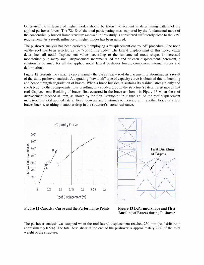
Otherwise, the influence of higher modes should be taken into account in determining pattern of the applied pushover forces. The 72.4% of the total participating mass captured by the fundamental mode of the concentrically braced frame structure assessed in this study is considered sufficiently close to the 75% requirement. As a result, influence of higher modes has been ignored.
The pushover analysis has been carried out employing a “displacement-controlled” procedure. One node on the roof has been selected as the “controlling node”. The lateral displacement of this node, which determines all nodal displacement values according to the fundamental mode shape, is increased monotonically in many small displacement increments. At the end of each displacement increment, a solution is obtained for all the applied nodal lateral pushover forces, component internal forces and deformations.
Figure 12 presents the capacity curve, namely the base shear – roof displacement relationship, as a result of the static pushover analysis. A degrading “sawtooth” type of capacity curve is obtained due to buckling and hence strength degradation of braces. When a brace buckles, it sustains its residual strength only and sheds load to other components, thus resulting in a sudden drop in the structure’s lateral resistance at that roof displacement. Buckling of braces first occurred in the brace as shown in Figure 13 when the roof displacement reached 40 mm, as shown by the first “sawtooth” in Figure 12. As the roof displacement increases, the total applied lateral force recovers and continues to increase until another brace or a few braces buckle, resulting in another drop in the structure’s lateral resistance.
Figure 12 Capacity Curve and the Performance Points Figure 13 Deformed Shape and First Buckling of Braces during Pushover
The pushover analysis was stopped when the roof lateral displacement reached 250 mm (roof drift ratio approximately 0.5%). The total base shear at the end of the pushover is approximately 22% of the total weight of the structure.
First Buckling of Braces

Determination of the Performance Points (Target Displacements)
Having obtained the capacity curve, the next step is to determine the performance points which are the points on the capacity curve representing the response of the structure to the design earthquakes and at which the seismic force and deformation demands meet the structure’s capacity. Two alternative methods, the capacity spectrum method recommended by ATC 40 [6] and the displacement coefficient method recommended by FEMA 273 [5], are commonly employed to determine the performance point. In this study, the displacement coefficient method will be employed due to its simplicity and ease of application.
The target (roof) displacement, δt, is calculated as follows:
2
2
3210 4πδ e
at
TSCCCC= (1)
where: 2
2
4πe
a
TS converts the spectral acceleration Sa to the spectral displacement Sd.
Te = effective period. In the case of the existing concentrically braced frame structure, the capacity curve is a straight line up to first “sawtooth” point where some braces buckle. Therefore, Te equals the initial period of the mode used for the pushover analysis, being 0.81 seconds.
C0 = the factor converting the spectral displacement to the roof displacement. It equals the product of the modal participation factor of the fundamental mode and the modal roof lateral displacement of this mode. In the case of the existing concentrically braced frame assessed in this study, C0 = 1.37 calculated according to SAP 2000 output of modal participation factor and roof displacement of the fundamental mode. C0 multiplied by Sd gives the elastic roof displacement.
C1 = modification factor to relate the elastic roof displacement to the maximum expected inelastic roof displacement. The effective period Te is greater than the second corner period of the design spectrum, resulting the value of C1 being unity according to FEMA 273 [5].
C2 = modification factor to consider the effect of inelastic hysteresis shape on the maximum inelastic displacement. The existing concentrically braced frame structure is classified as type 1 by FEMA 273 [5] and accordingly the value of C2 has been assigned a value of unity for the immediate occupancy performance objective and a value of 1.1 for the life safety performance objective.
C3 = modification factor to consider increased displacement due to P-∆ effect. For building with a positive post-yielding stiffness, C3 is set equal to 1.0 according to FEME 273 [5]. This condition applies to the existing concentrically braced structure assessed in this study, since the capacity curve obtained exhibits positive post-yielding stiffness. As a result, C3 = 1.0.
Considering a damping correction factor of 1.18, the maximum roof displacements (target displacements) under the two levels of design earthquake are calculated as 36 mm and 80 mm, respectively. The two performance points are shown in Figure 12 as points A and B respectively on the capacity curve. Displacement-Based Seismic Performance Evaluation Under the design earthquake corresponding to a PHGA = 0.14g, the roof displacement is 36 mm, resulting in a roof drift ratio of 0.07%. Compared with the roof drift ratio acceptance criteria of 0.5% for the immediate occupancy performance objective, the global building deformation is small and well within the acceptable value. On the component level, all components remained elastic with neither plastic hinges formed nor any braces buckled, as shown in Figure 12 by the performance point A. The component force demand-capacity

ratios are similar to those shown in Figure 7. It is therefore concluded that under the design earthquake event corresponding to a PHGA = 0.14g, the performance of the existing concentrically braced frame tower block structure satisfies the pre-defined immediate occupancy performance objective.
Under the design earthquake corresponding to a PHGA = 0.3g, the roof displacement is 80 mm, giving a roof drift ratio of 0.15%. This value is only one tenth of the acceptable roof drift ratio of 1.5% for the life safety performance objective.
On the component level, at the performance point B (roof displacement 80 mm), some braces have already buckled and degraded in stiffness and strength, as shown in Figure 14. The axial shortening of these buckled braces at the performance point B is approximately twice the axial shortening at initial buckling, well within the acceptable axial shortening limit of 6 times the axial compression shortening at initial buckling for I shape braces recommended in Table 5-8 of FEMA 273 for the life safety performance objective. Therefore, the performance of the existing steel concentrically braced frame tower block structure satisfies the life safety performance objective under the second level of design earthquake with a PHGA value of 0.3g.
DISCUSSIONS AND CONCLUDING REMARKS
This paper has carried out a seismic assessment of an existing steel concentrically braced frame structure. Both the conventional force-based methodology and the new displacement-based methodology have been employed. Their application, in particular the application of the new displacement-based methodology, has been illustrated. Differences in philosophy, application and conclusions of the two methodologies have been highlighted. On the basis of this study, the following observations and conclusions may be drawn.
Figure 14 Deformed Shape and Buckled Braces at Performance Point B during Pushover
Buckled Braces

Fundamental Difference in the Philosophy of the Two Methodologies In the conventional force based methodology, the fundamental philosophy is to satisfy design rules in the form of seismic building code provisions. It designs structural elements and components for strength, according to code seismic force reduction factors and details them for ductility in accordance with code detailing requirements. It does not require the designer to gain an understanding of the behaviour and performance of the structure under the design earthquake. A structure, new or existing, is considered adequate if it satisfies code strength and detailing requirements. In contrast, the displacement-based methodology emphasises the understanding of the behaviour and the quantification of the performance of the structure under the design earthquake. Damage to structural and non-structural components as well as contents and equipment is quantified in terms of displacement- (deformation-) based parameters. The deformation capacity and seismic deformation demand are assessed and quantified on a component-by-component and element-by-element basis. Furthermore, the displacement based methodology is within a more general framework of performance-based seismic engineering that provides clearly defined, both qualitatively and quantitatively, performance objectives of a structure under various levels of design earthquake corresponding to various levels of risk, according to the usage of the structure. From the point of view of historical evolution of seismic design and assessment methodology, the new displacement based methodology is a step forward towards a more comprehensive and more rational seismic design methodology. Shortcomings of the Conventional Force Based Methodology Some of the shortcomings of the conventional force-based methodology are particularly evident when assessing an existing structure that has not been designed in accordance with modern seismic codes. In particular, many existing structures do not have sufficient strength to resist the design earthquake elastically or nearly elastically and at the same time do not satisfy modern code ductile detailing requirements. Whilst satisfying modern code ductile detailing requirements ensures adequate ductility capacities, not satisfying these requirements does not necessarily imply no ductility capacity. A certain degree of ductility capacity may exist in structural components that do not satisfy modern detailing requirements, depending on the actual detailing measures provided. The force-based methodology naturally leads to the following question: what is the permitted force reduction factor for structures containing components not satisfying modern ductile detailing requirements? This question cannot be answered without first quantifying the ductility capacity of the structure and components. This question cannot be answered within the framework of the force-based methodology. Therefore, the force-based methodology would naturally lead to seismic retrofit strategies that either strengthen the components or provide additional ductile detailing measures or a combination of both. The goal is to satisfy seismic code requirements. The limited ductility capacity inherent in components not satisfying code ductile detailing requirements cannot be utilised within the framework of the force-based methodology. This point has been clearly demonstrated in this paper. Another shortcoming of the force-based methodology is that it cannot assess the degree of damage to structural and non-structural components, although it can identify those components likely to be overstressed under the design earthquake. This shortcoming stems from the fact that force-based response parameters, such as the force reduction factor, do not relate directly to damage, neither structural nor non-structural.

Advantages of the New Displacement-Based Methodology The above discussions on the shortcomings of the conventional force-based methodology suggest that whilst it may be adequate and may continue to serve as guidelines for design of new buildings and other types of structures, it may not be appropriate for seismic assessment of existing structures, particularly those not satisfying modern code ductile detailing requirements and responding to the design earthquake inelastically. This type of engineering problem is better addressed by quantifying the ductility (inelastic deformation) capacities of the existing structural components and then assessing the seismic deformation demands, namely by adopting the displacement-based methodology. Indeed, the world’s first displacement-based seismic engineering documents, FEMA 273 [5] and ATC 40 [6], are guidelines for seismic assessment and rehabilitation of existing structures. As demonstrated by the example in this paper, the displacement-based methodology results in a more realistic assessment of existing structures. This has been made possible by quantifying and utilising the ductility capacities of existing components not satisfying modern code ductile detailing requirements and focusing the attention of the design engineer on the comparison between the component deformation capacity and seismic deformation demands. It has been shown in this paper that whilst the force-based methodology can only conclude that certain components are overstressed under the second level of design earthquake, the displacement-based method can actually quantify the degree of damage, providing the design engineer with much more valuable information based on which it is possible to draw a different conclusion with respect to whether or not retrofit measures are required. It should also be pointed out that in cases where the structure responds elastically under the design earthquake, both methodologies are expected to lead to similar conclusion, as demonstrated in this paper in the case in which the existing structure is subjected to the first level of design earthquake.
REFERENCES
1. European Committee for Standardation (CEN), Eurocode 8: Design Provisions for Earthquake
Resistance of Structures – Part 1-4: General Rules – Strengthening and Repair of Buildings, European Prestandard ENV 1998-1-4, Brussels, 1996.
2. American Institute of Steel Construction, Load & Resistance Factor Design: Structural Members, Specification, & Codes, 1995.
3. Computers and Structures, Inc., SAP 2000 Analysis Reference, Berkeley, California, 1997. 2. European Committee for Standardation (CEN), Eurocode 8: Design Provisions for Earthquake
Resistance of Structures – Part 1-1: General Rules – Seismic Actions and General Requirements for Structures, European Prestandard ENV 1998-1-1, Brussels, 1996.
4. Federal Emergency Management Agency, NEHRP Guidelines for the Seismic Rehabilitation of Buildings, FEMA 273, Washington, D. C., 1997.
5. Applied Technology Council, Seismic Evaluation and Retrofit of Concrete buildings, ATC 40 Report, 1996.