Mobile Communication brief
80
Basics of Wireless and Mobile Communications Wireless Transmission Frequencies Signals Antenna Signal propagation Multiplexing Modulation Spread spectrum Cellular systems Media Access Schemes Motivation SDMA, FDMA, TDMA, CDMA Comparison Basic Functions in Mobile Systems Location management Handover Roaming
-
Upload
nise-mon-kuriakose -
Category
Documents
-
view
78 -
download
2
description
Mobile commn
Transcript of Mobile Communication brief

Basics of Wireless and Mobile Communications
Wireless Transmission Frequencies Signals Antenna Signal propagation Multiplexing Modulation Spread spectrum Cellular systems
Media Access Schemes Motivation SDMA, FDMA, TDMA, CDMA Comparison
Basic Functions in Mobile Systems Location management Handover Roaming

UMTS Networks 2Andreas Mitschele-Thiel, Jens Mückenheim October 2012
References
Jochen Schiller: Mobile Communications (German and English), 2nd edition, Addison-Wesley, 2003 (most of the material covered in this chapter is based on the book)
Holma, Toskala: WCDMA for UMTS. 3rd edition, Wiley, 2004

UMTS Networks 3Andreas Mitschele-Thiel, Jens Mückenheim October 2012
Mobile Communication Systems – the Issues:
What does it require? Provide telecommunition services
voice (conversation, messaging) data (fax, SMS/MMS, internet) video (conversation, streaming, broadcast)
anywhere coverage anytime ubiquitous connectivity, reachability wireless without cord/wire mobile in motion, on the move (terrestrial) secure integrity, identity, privacy, authenticity,
non-repudiation (Unleugbarkeit) reliable guaranteed quality of service

UMTS Networks 4Andreas Mitschele-Thiel, Jens Mückenheim October 2012
Frequencies for communication (spectrum)
VLF = Very Low Frequency UHF = Ultra High FrequencyLF = Low Frequency SHF = Super High FrequencyMF = Medium Frequency EHF = Extra High FrequencyHF = High Frequency UV = Ultraviolet LightVHF = Very High Frequency
Frequency and wave length:
= c / f wave length , speed of light c 300 x 106 m/s, frequency f
1 Mm300 Hz
10 km30 kHz
100 m3 MHz
1 m300 MHz
10 mm30 GHz
100 m3 THz
1 m300 THz
visible lightVLF LF MF HF VHF UHF SHF EHF infrared UV
optical transmissioncoax cabletwisted pair
GSM, DECT, UMTS, WLAN

UMTS Networks 5Andreas Mitschele-Thiel, Jens Mückenheim October 2012
Electromagnetic Spectrum
100 MHz: UKW Radio, VHF TV
400 MHz: UHF TV
450 MHz: C-Netz
900 MHz: GSM900
1800 MHz: GSM1800
1900 MHz: DECT
2000 MHz: UMTS (3G)
2400 MHz: WLAN, Bluetooth
2450 MHz: Mikrowellenherd
3500 MHz: WiMax
o

UMTS Networks 6Andreas Mitschele-Thiel, Jens Mückenheim October 2012
Frequencies for mobile communication
VHF-/UHF-ranges for mobile radio simple, small antennas good propagation characteristics (limited reflections, small path loss,
penetration of walls) typically used for radio & TV (terrestrial+satellite) broadcast,
wireless telecommunication (cordless/mobile phone)
SHF and higher for directed radio links, satellite communication small antenna, strong focus larger bandwidth available no penetration of walls
Mobile systems and wireless LANs use frequencies in UHF to SHF spectrum some systems planned up to EHF limitations due to absorption by water and oxygen molecules (resonance
frequencies)weather dependent fading, signal loss caused by heavy rainfall etc.

UMTS Networks 7Andreas Mitschele-Thiel, Jens Mückenheim October 2012
Frequencies and regulations
ITU-R holds auctions for new frequencies, manages frequency bands worldwide (WRC, World Radio Conferences)Examples of assigned frequency bands (in MHz):
Europe USA Japan
Cellular Phones (licensed)
GSM 450-457, 479-486/460-467,489-496, 890-915/935-960, 1710-1785/1805-1880 UMTS (FDD) 1920-1980, 2110-2190 UMTS (TDD) 1900-1920, 2020-2025
AMPS, TDMA, CDMA 824-849, 869-894 TDMA, CDMA, GSM 1850-1910, 1930-1990
PDC 810-826, 940-956, 1429-1465, 1477-1513
Cordless Phones (un-licensed)
CT1+ 885-887, 930-932 CT2 864-868 DECT 1880-1900
PACS 1850-1910, 1930-1990 PACS-UB 1910-1930
PHS 1895-1918 JCT 254-380
Wireless LANs (un-licensed)
IEEE 802.11 b 2400-2483 802.11a/HIPERLAN 2 5150-5350, 5470-5725
902-928 IEEE 802.11 2400-2483 5150-5350, 5725-5825
IEEE 802.11 2471-2497 5150-5250
Others RF-Control 27, 128, 418, 433, 868
RF-Control 315, 915
RF-Control 426, 868
WiMax (IEEE 802.16, licensed)
2.3GHz, 2.5GHz and 3.5GHz
2.3GHz, 2.5GHz and 3.5GHz
2.3GHz, 2.5GHz and 3.5GHz
Abbreviations:AMPS Advanced Mobile Phone
SystemCDMA Code Division Multiple
AccessCT Cordless TelephoneDECT Digital Enhanced
Cordless Telecommunications
GSM Global System for Mobile Communications
HIPERLAN High-Performance LAN
IEEE Institute of Electrical and Electronics Engineers
JCT Japanese Cordless Telephone
NMT Nordic Mobile TelephonePACS Personal Access
Communications SystemPACS-UB PACS- Unlicensed
BandPDC Pacific Digital CellularPHS Personal Handyphone
SystemTDMA Time Division Multiple
AccessWiMAX Worldwide
Interoperability for Microwave Access
o

UMTS Networks 8Andreas Mitschele-Thiel, Jens Mückenheim October 2012
UMTS Frequency Bands (FDD mode only)
Operating Band
Frequency Band
UL Frequencies UE transmit
(MHz)
DL FrequenciesUE receive
(MHz)
Typically used in region ...
I 2100 1920 - 1980 2110 - 2170 EU, Asia
II 1900 1850 - 1910 1930 - 1990 America
III 1800 1710 - 1785 1805 - 1880 EU (future use)
IV 1700 1710 - 1755 2110 - 2155 Japan
V 850 824 - 849 869 - 894 America, Australia, Brazil
VI 800 830 - 840 875 - 885 Japan
VII 2600 2500 - 2570 2620 - 2690 „Extension Band“
VIII 900 880 - 915 925 - 960 EU (future use)
IX 1800 1749.9 - 1784.9 1844.9 - 1879.9 Japan
X 1700 1710 - 1770 2110 - 2170 America/US
o

UMTS Networks 9Andreas Mitschele-Thiel, Jens Mückenheim October 2012
UMTS Frequency Bands (FDD mode only), Germany
Operator Uplink (MHz) Downlink (MHz) Carriers Auction Price
Vodafone 1920,3 – 1930,2 2110,3 – 2120,2 2x10 MHz 16,47 Mrd. DM (8,42 Mrd. €)
Currently spare
1930,2 – 1940,1 2120,2 – 2130,1 2x10 MHz 16,45 Mrd. DM Group 3G
(Marke Quam)E-Plus 1940,1 – 1950,0 2130,1 – 2140,0 2x10 MHz 16,42 Mrd. DM (8,39
Mrd. €)
Currently spare
1950,0 – 1959,9 2140,0 – 2149,9 2x10 MHz (16,37 Mrd. DM Mobilcom; returned)
O2 1959,9 – 1969,8 2149,9 – 2159,8 2x10 MHz 16,52 Mrd. DM (8,45 Mrd. €)
T-Mobile 1969,8 – 1979,7 2159,8 – 2169,7 2x10 MHz 16,58 Mrd. DM (8,48 Mrd. €)
In 2000, the UMTS frequency bands were auctioned in Germany.6 operators won 10 MHz each, for total 50 B€
o

UMTS Networks 10Andreas Mitschele-Thiel, Jens Mückenheim October 2012
Basic Lower Layer Model for Wireless TransmissionTransmit direction Receive direction
Data link layer – media access– fragmentation – reassembly– frame error protection – frame error detection– multiplexing – demultiplex
Physical layer – encryption – decryption– coding, forward error protection
DigitalSignal
Processing– decoding,bit error correction
– interleaving – deinterleaving– modulation – demodulation– D/A conversion, signal generation
– A/D conversion; (signal equalization)
– transmit – receive
Wireless Channel(path loss)
– Intersymbol-Interference (distortion of own signal)– Intercell-Interference(multiple users)
– Intracell-Interference (multiple users) –Thermal Noise o

UMTS Networks 11Andreas Mitschele-Thiel, Jens Mückenheim October 2012
Signals in general
physical representation of data function of time and location signal parameters: parameters representing the value of data classification
continuous time/discrete time continuous values/discrete values analog signal = continuous time and continuous values digital signal = discrete time and discrete values
signal parameters of periodic signals: period T, frequency f=1/T, amplitude A, phase shift sine wave as special periodic signal for a carrier:
s(t) = At sin(2 ft t + t)
amplitude frequency phase shift

UMTS Networks 12Andreas Mitschele-Thiel, Jens Mückenheim October 2012
Composed signals transferred into frequency domain using Fourier transformation
Digital signals need infinite frequencies for perfect transmission modulation with a carrier frequency for transmission (analog signal!)
Signal representations
f [Hz]
A [V]
I= M cos
Q = M sin
A [V]
t[s]
amplitude (time domain)
frequency spectrum (frequency domain)
phase state diagram (amplitude M and phase in polar coordinates)
UMTS Networks 13Andreas Mitschele-Thiel, Jens Mückenheim October 2012
Fourier representation of periodic signals
)2cos()2sin(21)(
11nftbnftactg
nn
nn
1
0
1
0t t
ideal periodic signal real composition(based on harmonics)
Every periodic signal g(t) can be constructed by

UMTS Networks 14Andreas Mitschele-Thiel, Jens Mückenheim October 2012
Signal propagation
Propagation in free space always like light (straight line, line of sight)
Receiving power proportional to1/d² (ideal), 1/dα (α=3...4 realistically)(d = distance between sender and receiver)
Receiving power additionally influenced by fading (frequency dependent) shadowing reflection at large obstacles scattering at small obstacles diffraction at edges
reflection scattering diffractionshadowing

UMTS Networks 15Andreas Mitschele-Thiel, Jens Mückenheim October 2012
Radio Propagation: Received Power due to Pathloss
1m 10m 100mIdeal line-of sight(d-2): 1 1:100 1:10000
Realistic propagation 1 1:3000 to 1:10 Mio to(d-3.5…4): 1:10000 1:100 Mio35-40
dB
35-40 dB

UMTS Networks 16Andreas Mitschele-Thiel, Jens Mückenheim October 2012
Signal can take many different paths between sender and receiver due to reflection, scattering, diffraction
Time dispersion: signal is dispersed over time interference with “neighbor” symbols, Inter Symbol Interference (ISI)
The signal reaches a receiver directly and phase shifted distorted signal depending on the phases of the different parts
Multipath propagation
signal at sendersignal at receiver
Delayed signal rec’dvia longer path
Signal receivedby direct path

UMTS Networks 17Andreas Mitschele-Thiel, Jens Mückenheim October 2012
Effects of mobility – Fading
Channel characteristics change over time and location signal paths change different delay variations of different signal parts (frequencies) different phases of signal parts quick changes in the power received (short-term fading or fast fading)
Additional changes in distance to sender obstacles further away slow changes in the average power
received (long-term fading or slow fading)
short-term fading
long-termfading
t
power

UMTS Networks 18Andreas Mitschele-Thiel, Jens Mückenheim October 2012
Fast Fading
simulation showing time and frequency dependency of Rayleigh fading
V = 110km/h 900MHz

UMTS Networks 19Andreas Mitschele-Thiel, Jens Mückenheim October 2012
Signal propagation ranges
distance
sender
transmission
detection
interference
Transmission range communication possible low error rate
Detection range detection of the signal
possible no communication
possible Interference range
signal may not be detected
signal adds to the background noise

UMTS Networks 20Andreas Mitschele-Thiel, Jens Mückenheim October 2012
Interference
UMTS Networks 21Andreas Mitschele-Thiel, Jens Mückenheim October 2012
Carrier to Interference Ratio (CIR, C/I)
(Uplink Situation)
Ratio of Carrier-to-Interference power at the receiver
The minimum required CIR depends on the system and the signal processing potential of the receiver technology
Typical in GSM:C/I=15dB (Factor 32)
NICCIRj

UMTS Networks 22Andreas Mitschele-Thiel, Jens Mückenheim October 2012
Range limited systems (lack of coverage)
Mobile stations located far away from BS (at cell border or even beyond the coverage zone)
C at the receiver is too low, because the path loss between sender and receiver is too high
C/I is too low
No signal reception possible

UMTS Networks 23Andreas Mitschele-Thiel, Jens Mückenheim October 2012
Interference limited systems (lack of capacity)
Mobile station is within coverage zone C is sufficient, but too much
interference I at the receiver
C/I is too low
No more resources / capacity left

UMTS Networks 24Andreas Mitschele-Thiel, Jens Mückenheim October 2012
Information Theory: Channel Capacity (1)
Bandwidth limited Additive White Gaussian Noise (AWGN) channel
Gaussian codebooks Single transmit antenna Single receive antenna (SISO)
Shannon (1950): Channel Capacity <= Maximum mutual information between sink and source
Signal-to-noise ratio SNR
o
UMTS Networks 25Andreas Mitschele-Thiel, Jens Mückenheim October 2012
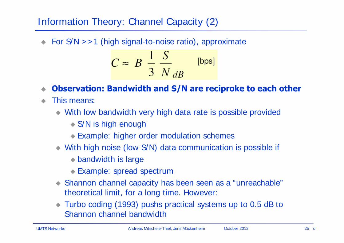
Information Theory: Channel Capacity (2)
For S/N >>1 (high signal-to-noise ratio), approximate
Observation: Bandwidth and S/N are reciproke to each other This means:
With low bandwidth very high data rate is possible provided S/N is high enough Example: higher order modulation schemes
With high noise (low S/N) data communication is possible if bandwidth is large Example: spread spectrum
Shannon channel capacity has been seen as a “unreachable” theoretical limit, for a long time. However:
Turbo coding (1993) pushs practical systems up to 0.5 dB to Shannon channel bandwidth
o
UMTS Networks 26Andreas Mitschele-Thiel, Jens Mückenheim October 2012
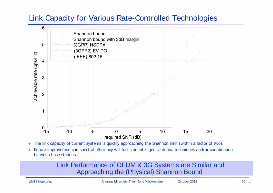
Link Capacity for Various Rate-Controlled Technologies
The link capacity of current systems is quickly approaching the Shannon limit (within a factor of two). Future improvements in spectral efficiency will focus on intelligent antenna techniques and/or coordination
between base stations.
Link Performance of OFDM & 3G Systems are Similar and Approaching the (Physical) Shannon Bound
-15 -10 -5 0 5 10 15 200
1
2
3
4
5
6
required SNR (dB)
achi
evab
le r
ate
(bps
/Hz)
Shannon boundShannon bound with 3dB margin
(3GPP2) EV-DO(IEEE) 802.16
(3GPP) HSDPA
o

UMTS Networks 27Andreas Mitschele-Thiel, Jens Mückenheim October 2012
Radiation and reception of electromagnetic waves, coupling of wires to space for radio transmission
Isotropic radiator: equal radiation in all directions (three dimensional) -only a theoretical reference antenna
Real antennas always have directive effects (vertically and/or horizontally)
Radiation pattern: measurement of radiation around an antenna
Antennas: isotropic radiator
zy
x
z
y x idealisotropicradiator
UMTS Networks 28Andreas Mitschele-Thiel, Jens Mückenheim October 2012
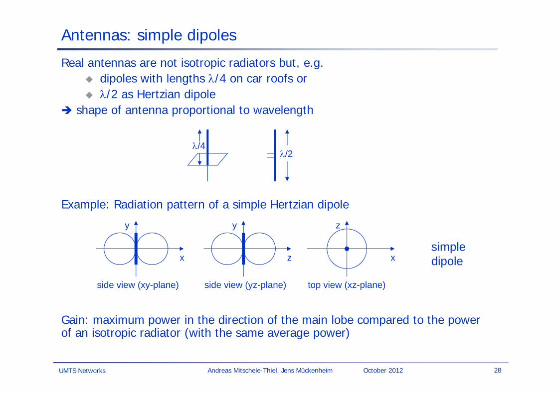
Antennas: simple dipoles
Real antennas are not isotropic radiators but, e.g. dipoles with lengths /4 on car roofs or /2 as Hertzian dipole
shape of antenna proportional to wavelength
Example: Radiation pattern of a simple Hertzian dipole
Gain: maximum power in the direction of the main lobe compared to the power of an isotropic radiator (with the same average power)
side view (xy-plane)
x
y
side view (yz-plane)
z
y
top view (xz-plane)
x
z
simpledipole
/4/2

UMTS Networks 29Andreas Mitschele-Thiel, Jens Mückenheim October 2012
Antennas: directed and sectorized
side view (xy-plane)
x
y
side view (yz-plane)
z
y
top view (xz-plane)
x
z
top view, 3 sector
x
z
top view, 6 sector
x
z
Often used for microwave connections (narrow directed beam) or base stations for cellular networks (sectorized cells)
directedantenna
sectorizedantenna
UMTS Networks 30Andreas Mitschele-Thiel, Jens Mückenheim October 2012
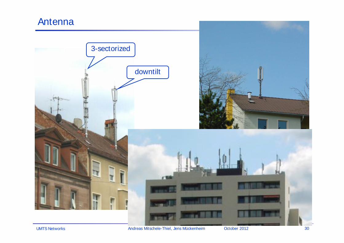
Antenna
downtilt
3-sectorized

UMTS Networks 31Andreas Mitschele-Thiel, Jens Mückenheim October 2012
Real world propagation examples

UMTS Networks 32Andreas Mitschele-Thiel, Jens Mückenheim October 2012
Antennas: diversity
Grouping of 2 or more antennas multi-element antenna arrays
Antenna diversity switched diversity, selection diversity
receiver chooses antenna with largest output
diversity combining combine output power to produce gain cophasing needed to avoid cancellation
+
/4/2/4
ground plane
/2/2
+
/2
UMTS Networks 33Andreas Mitschele-Thiel, Jens Mückenheim October 2012
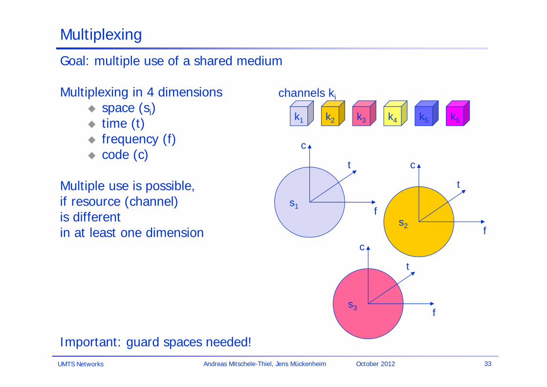
Goal: multiple use of a shared medium
Multiplexing in 4 dimensions space (si) time (t) frequency (f) code (c)
Multiple use is possible,if resource (channel) is different in at least one dimension
Important: guard spaces needed!
s2
s3
s1
Multiplexing
f
t
c
k2 k3 k4 k5 k6k1
f
t
c
f
t
c
channels ki

UMTS Networks 34Andreas Mitschele-Thiel, Jens Mückenheim October 2012
Frequency multiplex
Separation of the whole spectrum into smaller frequency bandsA channel gets a certain band of the spectrum for the whole time
Advantages:
no dynamic coordination needed applicable to analog signals
Disadvantages: waste of bandwidth
if the traffic is distributed unevenly
inflexible guard space
k2 k3 k4 k5 k6k1
f
t
c

UMTS Networks 35Andreas Mitschele-Thiel, Jens Mückenheim October 2012
f
t
c
k2 k3 k4 k5 k6k1
Time multiplex
A channel gets the whole spectrum for a certain amount of time
Advantages: only one carrier in the
medium at any time throughput high even
for many users
Disadvantages: precise synchronization
needed

UMTS Networks 36Andreas Mitschele-Thiel, Jens Mückenheim October 2012
f
Time and frequency multiplex
Combination of both methodsA channel gets a certain frequency band for a certain amount of timeExample: GSM (frequency hopping)
Advantages: some (weak) protection against
tapping protection against frequency
selective interferencebut: precise coordination required
t
c
k2 k3 k4 k5 k6k1

UMTS Networks 37Andreas Mitschele-Thiel, Jens Mückenheim October 2012
Code multiplex
Each channel has a unique codeAll channels use the same spectrum at the same time
Advantages: bandwidth efficient no coordination and synchronization
necessary good protection against interference and
tapping
Disadvantages: complex receivers (signal regeneration)
Implemented using spread spectrum technology
k2 k3 k4 k5 k6k1
f
t
c
UMTS Networks 38Andreas Mitschele-Thiel, Jens Mückenheim October 2012
Cellular systems: Space Division Multiplex
Cell structure implements space division multiplex: base station covers a certain transmission area (cell)
Mobile stations communicate only via the base station
Advantages of cell structures: higher capacity, higher number of users less transmission power needed more robust, decentralized base station deals with interference, transmission area, etc. locally
Disadvantages: fixed network needed for the base stations handover (changing from one cell to another) necessary interference with other cells
Cell sizes vary from 10s of meters in urban areas to many km in rural areas (e.g. maximum of 35 km radius in GSM)

UMTS Networks 39Andreas Mitschele-Thiel, Jens Mückenheim October 2012
Cellular systems: Frequency planning IFrequency reuse only with a certain distance between the base stations
Typical (hexagon) model:
reuse-3 cluster: reuse-7 cluster:
Other regular pattern: reuse-19 the frequency reuse pattern determines the experienced CIR Fixed frequency assignment:
certain frequencies are assigned to a certain cell problem: different traffic load in different cells
Dynamic frequency assignment: base station chooses frequencies depending on the frequencies already used in
neighbor cells more capacity in cells with more traffic assignment can also be based on interference measurements
f4f5
f1f3
f2
f6
f7
f4f5
f1f3
f2
f6
f7
f4f5
f1f3
f2
f6
f7f2
f1f3
f2
f1f3
f2
f1f3

UMTS Networks 40Andreas Mitschele-Thiel, Jens Mückenheim October 2012
Cellular systems: frequency planning II
f1f2
f3f2
f1
f1
f2
f3f2
f3f1
f2f1
f3f3
f3f3
f3
f4f5
f1f3
f2
f6
f7
f3f2
f4f5
f1f3
f5f6
f7f2
f2
f1f1 f1f2f3
f2f3
f2f3h1
h2h3g1
g2
g3
h1h2h3g1
g2
g3g1
g2
g3
3 cell cluster
7 cell cluster
3 cell clusterwith 3 sector antennas

UMTS Networks 41Andreas Mitschele-Thiel, Jens Mückenheim October 2012
Spread spectrum technology:
Problem of radio transmission: frequency dependent fading can wipe out narrow band signals for duration of the interferenceSolution: spread the narrow band signal into a broad band signal using a special code
protection against narrow band interference
Side effects: coexistence of several signals without dynamic coordination tap-proof
Alternatives: Direct Sequence (UMTS) Frequency Hopping (slow FH: GSM, fast FH: Bluetooth)
detection atreceiver
interferencespread signal
signal (despreaded)
spreadinterference
f f
power power

UMTS Networks 42Andreas Mitschele-Thiel, Jens Mückenheim October 2012
Effects of spreading and interference
dP/df
f
i) narrow band signal
dP/df
f
ii) spreaded signal (broadband signal)
sender
dP/df
f
iii) addition of interference
dP/df
f
iv) despreadedsignal
receiverf
v) application of bandpass filter
user signalbroadband interferencenarrowband interference
dP/df

UMTS Networks 43Andreas Mitschele-Thiel, Jens Mückenheim October 2012
Spreading and frequency selective fading
frequency
channelquality
1 23
4
5 6
narrow bandsignal
guard space
22
22
2
frequency
channelquality
1
spreadspectrum
narrowband interference without spread spectrum
spread spectrum to limitnarrowband interference

UMTS Networks 44Andreas Mitschele-Thiel, Jens Mückenheim October 2012
DSSS (Direct Sequence Spread Spectrum) I
XOR of the signal with pseudo-random number (chipping sequence) many chips per bit (e.g., 128) result in higher bandwidth of the signal
Advantages reduces frequency selective
fading in cellular networks
base stations can use the same frequency range
several base stations can detect and recover the signal
soft handover
Disadvantages precise power control needed
user data
chipping sequence
resultingsignal
0 1
0 1 1 0 1 0 1 01 0 0 1 11
XOR
0 1 1 0 0 1 0 11 0 1 0 01
=
tb
tc
tb: bit periodtc: chip period
UMTS Networks 45Andreas Mitschele-Thiel, Jens Mückenheim October 2012
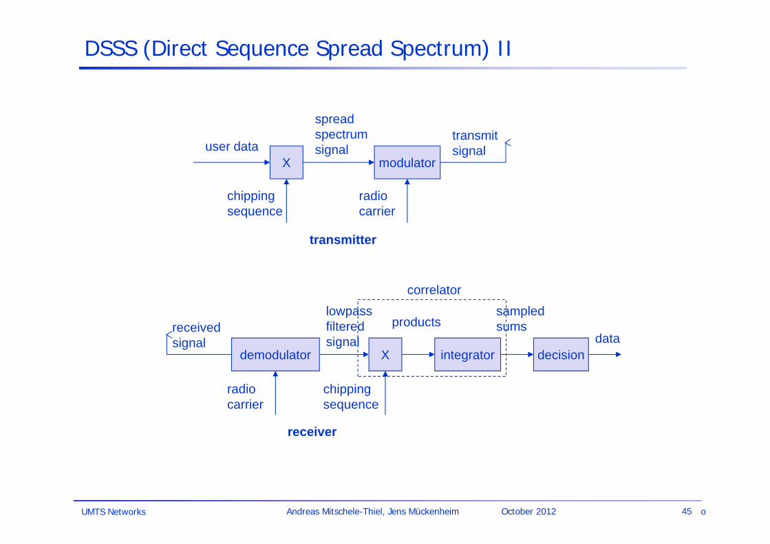
DSSS (Direct Sequence Spread Spectrum) II
Xuser data
chippingsequence
modulator
radiocarrier
spreadspectrumsignal
transmitsignal
transmitter
demodulator
receivedsignal
radiocarrier
X
chippingsequence
lowpassfilteredsignal
receiver
integrator
products
decisiondata
sampledsums
correlator
o

UMTS Networks 46Andreas Mitschele-Thiel, Jens Mückenheim October 2012
Modulation
“The shaping of a (baseband) signal to convey information”.
Basic schemes Amplitude Modulation (AM) Frequency Modulation (FM) Phase Modulation (PM)
Digital modulation digital data is translated into an analog signal (baseband) ASK, FSK, PSK differences in spectral efficiency, power efficiency, robustness
Motivation for modulation smaller antennas (e.g., /4) medium characteristics Frequency Division Multiplexing spectrum availability

UMTS Networks 47Andreas Mitschele-Thiel, Jens Mückenheim October 2012
Modulation and demodulation
synchronizationdecision
digitaldataanalog
demodulation
radiocarrier
analogbasebandsignal
101101001 radio receiver
digitalmodulation
digitaldata analog
modulation
radiocarrier
analogbasebandsignal
101101001 radio transmitter
o

UMTS Networks 48Andreas Mitschele-Thiel, Jens Mückenheim October 2012
Digital modulation
Modulation of digital signals known as Shift Keying
Amplitude Shift Keying (ASK): very simple low bandwidth requirements very susceptible to interference
Frequency Shift Keying (FSK): needs larger bandwidth
Phase Shift Keying (PSK): more complex robust against interference
1 0 1
t
1 0 1
t
1 0 1
t

UMTS Networks 49Andreas Mitschele-Thiel, Jens Mückenheim October 2012
Advanced Frequency Shift Keying
bandwidth needed for FSK depends on the distance between the carrier frequencies
Idea: special pre-computation avoids sudden phase shifts MSK (Minimum Shift Keying)
MSK technique: bit stream is separated into even and odd bits, the duration of each bit is
doubled depending on the bit values (even, odd) the higher or lower frequency,
original or inverted is chosen the frequency of one carrier is twice the frequency of the other, eliminating
abrupt phase changes
even higher bandwidth efficiency using a Gaussian low-pass filter GMSK (Gaussian MSK), used for GSM and DECT

UMTS Networks 50Andreas Mitschele-Thiel, Jens Mückenheim October 2012
Example of MSK
data
even bits
odd bits
1 1 1 1 000
t
low frequency
highfrequency
MSKsignal
bit
even 0 1 0 1
odd 0 0 1 1
signal h l l hvalue - - + +
h: high frequencyl: low frequency+: original signal-: inverted signal
No phase shifts!
Transformation scheme

UMTS Networks 51Andreas Mitschele-Thiel, Jens Mückenheim October 2012
Advanced Phase Shift Keying
BPSK (Binary Phase Shift Keying): bit value 0: sine wave bit value 1: inverted sine wave very simple PSK low spectral efficiency robust, used e.g. in satellite systems
QPSK (Quadrature Phase Shift Keying):
2 bits coded as one symbol symbol determines shift of sine wave needs less bandwidth compared to BPSK more complex used in UMTS and EDGE (8-PSK) often also transmission of relative, not absolute phase shift:
DQPSK - Differential QPSK (IS-136, PHS)
Puls filtering of baseband to avoid sudden phase shifts => reduce bandwidth of modulated signal
Q
I01
Q
I
11
01
10
00

UMTS Networks 52Andreas Mitschele-Thiel, Jens Mückenheim October 2012
Quadrature Amplitude Modulation
Quadrature Amplitude Modulation (QAM) combines amplitude and phase modulation it is possible to code n bits using one symbol 2n discrete levels: e.g. 16-QAM, 64-QAM
n=2: 4-QAM identical to QPSK bit error rate increases with n, but less errors compared to comparable
PSK schemes
Example: 16-QAM (1 symbol = 16 levels = 4 bits)Symbols 0011 and 0001 have the same phase, but different amplitude0000 and 1000 have different phase, but same amplitude
also: 64-QAM (1 symbol = 64 levels = 6 bits)
QAM is used in UMTS HSDPA (16-QAM) UMTS LTE (64-QAM) standard 9600 bit/s modems
0000
0001
0011
1000
Q
I
0010
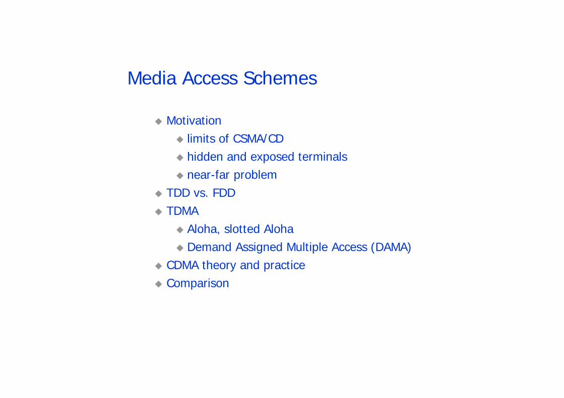
Media Access Schemes
Motivation limits of CSMA/CD hidden and exposed terminals near-far problem
TDD vs. FDD TDMA
Aloha, slotted Aloha Demand Assigned Multiple Access (DAMA)
CDMA theory and practice Comparison

UMTS Networks 54Andreas Mitschele-Thiel, Jens Mückenheim October 2012
Media Access: Motivation
The problem: multiple users compete for a common, shared resource (medium)
Can we apply media access methods from fixed networks?
Example CSMA/CD Carrier Sense Multiple Access with Collision Detection (IEEE 802.3) send as soon as the medium is free (carrier sensing – CS) listen to the medium, if a collision occurs stop transmission and jam
(collision detection – CD)
Problems in wireless networks signal strength decreases (at least) proportional to the square of the
distance the sender would apply CS and CD, but the collisions happen at the
receiver it might be the case that a sender cannot “hear” the collision, i.e., CD
does not work furthermore, CS might not work if, e.g., a terminal is “hidden”

UMTS Networks 55Andreas Mitschele-Thiel, Jens Mückenheim October 2012
Hidden terminals A sends to B, C cannot receive A C wants to send to B, C senses a “free” medium -> CS fails collision at B: A cannot detect the collision -> CD fails A is “hidden” for C
Exposed terminals
B sends to A, C wants to send to another terminal (not A or B) C has to wait, CS signals a medium in use but A is outside the radio range of C, therefore waiting is not
necessary C is “exposed” to B
Motivation - hidden and exposed terminals
BA C
BA C
UMTS Networks 56Andreas Mitschele-Thiel, Jens Mückenheim October 2012
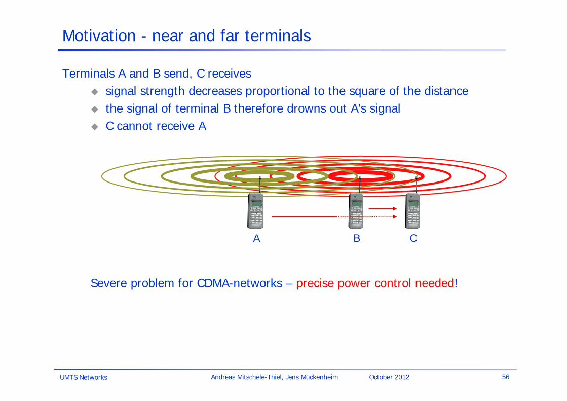
Terminals A and B send, C receives signal strength decreases proportional to the square of the distance the signal of terminal B therefore drowns out A’s signal C cannot receive A
Severe problem for CDMA-networks – precise power control needed!
Motivation - near and far terminals
A B C

UMTS Networks 57Andreas Mitschele-Thiel, Jens Mückenheim October 2012
Access methods SDMA/FDMA/TDMA
SDMA (Space Division Multiple Access) segment space into sectors, use directed antennas cell structure
FDMA (Frequency Division Multiple Access) assign a certain frequency to a transmission channel between a sender
and a receiver permanent (e.g., radio broadcast), slow hopping (e.g. GSM), fast
hopping (FHSS, Frequency Hopping Spread Spectrum)TDMA (Time Division Multiple Access)
assign the fixed sending frequency to a transmission channel between a sender and a receiver for a certain amount of time
The multiplexing schemes presented previously are now used to control medium access!
UMTS Networks 58Andreas Mitschele-Thiel, Jens Mückenheim October 2012
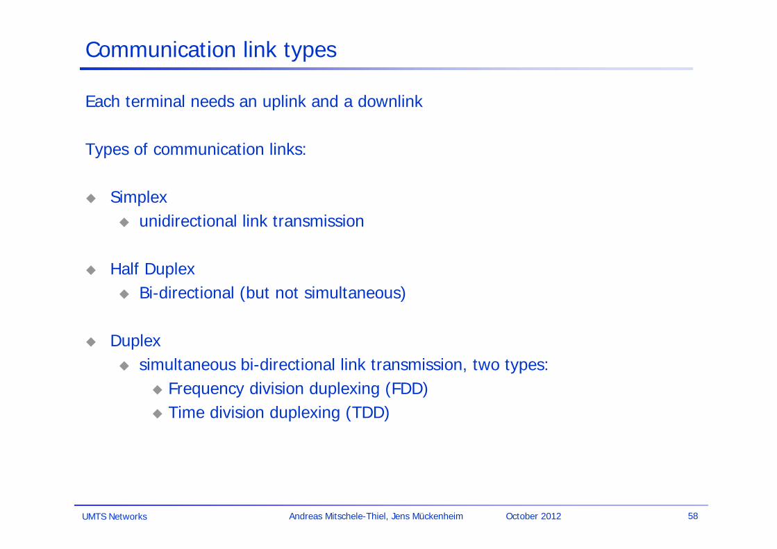
Communication link types
Each terminal needs an uplink and a downlink
Types of communication links:
Simplex unidirectional link transmission
Half Duplex Bi-directional (but not simultaneous)
Duplex simultaneous bi-directional link transmission, two types:
Frequency division duplexing (FDD) Time division duplexing (TDD)

UMTS Networks 59Andreas Mitschele-Thiel, Jens Mückenheim October 2012
Duplex modes
Frequency Division Duplex (FDD)
Separate frequency bands for up- and downlink
+ separation of uplink and downlink interference
- no support for asymmetric traffic
Examples: UMTS, GSM, IS-95, AMPS
Fd
Fu
TdTu
TdTu
Time Division Duplex (TDD)
Separation of up- and downlink traffic on time axis
+ support for asymmetric traffic
- mix of uplink and downlink interference on single band
Examples: DECT, UMTS (TDD)
UMTS Networks 60Andreas Mitschele-Thiel, Jens Mückenheim October 2012
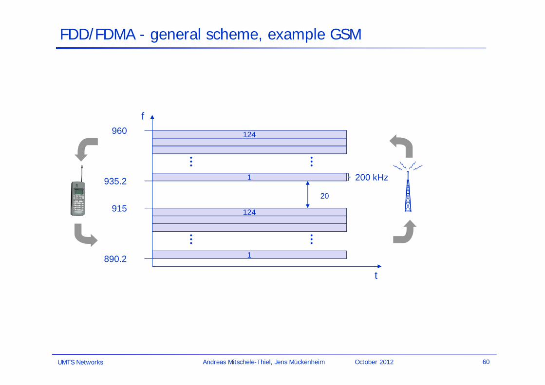
FDD/FDMA - general scheme, example GSM
f
t
124
1
124
1
20
200 kHz
890.2
935.2
915
960

UMTS Networks 61Andreas Mitschele-Thiel, Jens Mückenheim October 2012
TDD/TDMA - general scheme, example DECT
1 2 3 11 12 1 2 3 11 12
tdownlink uplink
417 µs

UMTS Networks 62Andreas Mitschele-Thiel, Jens Mückenheim October 2012
Mechanism random, distributed (no central arbiter), time-multiplex Slotted Aloha additionally uses time-slots, sending must always start at
slot boundaries
Aloha
Slotted Aloha
Aloha/slotted aloha
sender A
sender B
sender C
collision
sender A
sender B
sender C
collision
t
t

UMTS Networks 63Andreas Mitschele-Thiel, Jens Mückenheim October 2012
DAMA - Demand Assigned Multiple Access
Channel efficiency only 18% for Aloha, 36% for Slotted Aloha (assuming Poisson distribution for packet arrival and packet length)
Reservation can increase efficiency to 80% a sender reserves a future time-slot sending within this reserved time-slot is possible without collision reservation also causes higher delays typical scheme for satellite links application to packet data, e.g. in GPRS and UMTS
Examples for reservation algorithms: Explicit Reservation (Reservation-ALOHA) Implicit Reservation (PRMA) Reservation-TDMA

UMTS Networks 64Andreas Mitschele-Thiel, Jens Mückenheim October 2012
Access method DAMA: Explicit Reservation
Explicit Reservation (Reservation Aloha):Two modes:
ALOHA mode for reservation:competition for small reservation slots, collisions possible
reserved mode for data transmission within successful reserved slots (no collisions possible)
synchronisation: it is important for all stations to keep the reservation list consistent at any point in time and, therefore, all stations have to synchronize from time to time
Aloha reserved Aloha reserved Aloha reserved Aloha
collision
t

UMTS Networks 65Andreas Mitschele-Thiel, Jens Mückenheim October 2012
Access method CDMA
CDMA (Code Division Multiple Access) all terminals send on the same frequency probably at the same time and
can use the whole bandwidth of the transmission channel each sender has a unique random number, the sender XORs the signal with
this random number the receiver can “tune” into this signal if it knows the pseudo random
number, tuning is done via a correlation function
Advantages: all terminals can use the same frequency, less planning needed huge code space (e.g. 232) compared to frequency space interference (e.g. white noise) is not coded forward error correction and encryption can be easily integrated
Disadvantages: higher complexity of a receiver (receiver cannot just listen into the medium
and start receiving if there is a signal) all signals should have the same strength at a receiver (power control)

UMTS Networks 66Andreas Mitschele-Thiel, Jens Mückenheim October 2012
CDMA Principle
Code 0
Code 1
Code 2
data 0
data 1
data 2
Code 0
Code 1
Code 2
data 0
data 1
data 2
sender (base station) receiver (terminal)
Transmission viaair interface

UMTS Networks 67Andreas Mitschele-Thiel, Jens Mückenheim October 2012
CDMA by example
Source 2
Source 1
data stream A & B
Code 2
Code 1
spreading
Source 2 spread
Source 1 spread
spreaded signal

UMTS Networks 68Andreas Mitschele-Thiel, Jens Mückenheim October 2012
CDMA by example
Sum of Sources Spread
+
overlay of signals
Sum of Sources Spread + Noise
transmission and distortion (noise and interference)
Despread Source 2
Despread Source 1
decoding and despreading
UMTS Networks 69Andreas Mitschele-Thiel, Jens Mückenheim October 2012
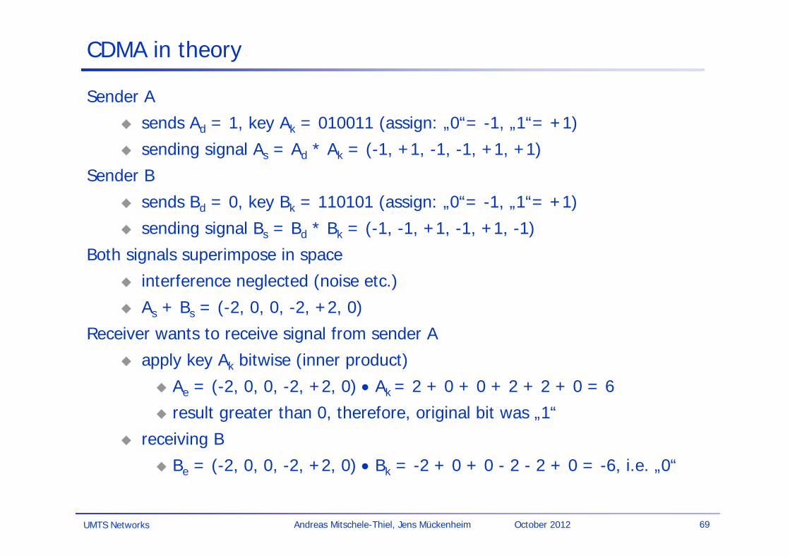
CDMA in theory
Sender A
sends Ad = 1, key Ak = 010011 (assign: „0“= -1, „1“= +1)
sending signal As = Ad * Ak = (-1, +1, -1, -1, +1, +1)
Sender B
sends Bd = 0, key Bk = 110101 (assign: „0“= -1, „1“= +1)
sending signal Bs = Bd * Bk = (-1, -1, +1, -1, +1, -1)
Both signals superimpose in space
interference neglected (noise etc.)
As + Bs = (-2, 0, 0, -2, +2, 0)
Receiver wants to receive signal from sender A
apply key Ak bitwise (inner product)
Ae = (-2, 0, 0, -2, +2, 0) Ak = 2 + 0 + 0 + 2 + 2 + 0 = 6
result greater than 0, therefore, original bit was „1“
receiving B
Be = (-2, 0, 0, -2, +2, 0) Bk = -2 + 0 + 0 - 2 - 2 + 0 = -6, i.e. „0“
UMTS Networks 70Andreas Mitschele-Thiel, Jens Mückenheim October 2012
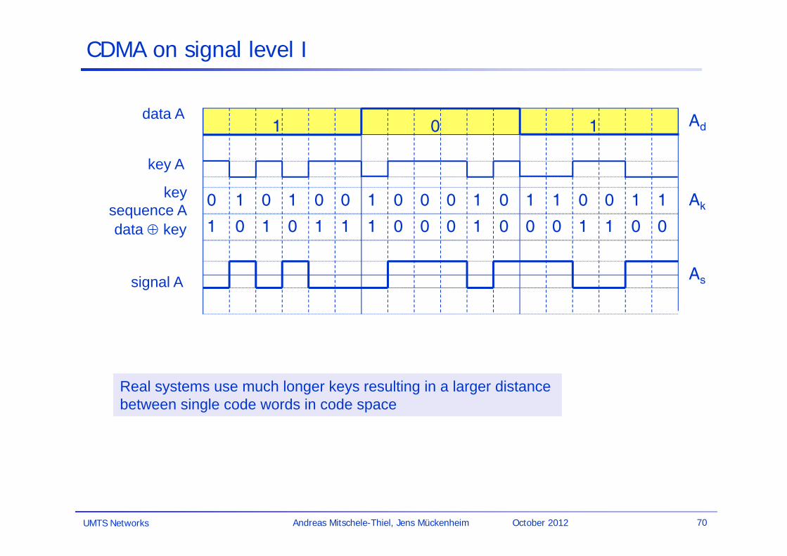
CDMA on signal level I
data A
key A
signal A
data key
keysequence A
Real systems use much longer keys resulting in a larger distance between single code words in code space
1 0 1
10 0 1 0 0 1 0 0 0 1 0 1 1 0 0 1 1
01 1 0 1 1 1 0 0 0 1 0 0 0 1 1 0 0
Ad
Ak
As

UMTS Networks 71Andreas Mitschele-Thiel, Jens Mückenheim October 2012
CDMA on signal level II
signal A
data B
key Bkey
sequence B
signal B
As + Bs
data key
1 0 0
00 0 1 1 0 1 0 1 0 0 0 0 1 0 1 1 1
11 1 0 0 1 1 0 1 0 0 0 0 1 0 1 1 1
Bd
Bk
Bs
As
1
0
-1

UMTS Networks 72Andreas Mitschele-Thiel, Jens Mückenheim October 2012
CDMA on signal level III
Ak
(As + Bs) * Ak
integratoroutput
comparatoroutput
As + Bs
data A
1 0 1
1 0 1 Ad
1
0
-1
1
-1
1
0
-1

UMTS Networks 73Andreas Mitschele-Thiel, Jens Mückenheim October 2012
CDMA on signal level IV
integratoroutput
comparatoroutput
Bk
(As + Bs) * Bk
As + Bs
data B
1 0 0
1 0 0 Bd
1
0
-1
1
-1
1
0
-1

UMTS Networks 74Andreas Mitschele-Thiel, Jens Mückenheim October 2012
comparatoroutput
CDMA on signal level V
wrongkey K
integratoroutput
(As + Bs) * K
As + Bs
(0) (0) ?
Assumptions orthogonality of keys neglectance of noise no differences in signal level => precise power control
1
0
-1
1
-1
1
0
-1

UMTS Networks 75Andreas Mitschele-Thiel, Jens Mückenheim October 2012
Comparison SDMA/TDMA/FDMA/CDMA
Approach SDMA TDMA FDMA CDMA Idea segment space into
cells/sectors segment sending time into disjoint time-slots, demand driven or fixed patterns
segment the frequency band into disjoint sub-bands
spread the spectrum using orthogonal codes
Terminals only one terminal can be active in one cell/one sector
all terminals are active for short periods of time on the same frequency
every terminal has its own frequency, uninterrupted
all terminals can be active at the same place at the same moment, uninterrupted
Signal separation
cell structure, directed antennas
synchronization in the time domain
filtering in the frequency domain
code plus special receivers
Advantages very simple, increases capacity per km²
established, fully digital, flexible
simple, established, robust
flexible, less frequency planning needed, soft handover
Dis-advantages
inflexible, antennas typically fixed
guard space needed (multipath propagation), synchronization difficult
inflexible, frequencies are a scarce resource
complex receivers, needs more complicated power control for senders
Comment only in combination with TDMA, FDMA or CDMA useful
standard in fixed networks, together with FDMA/SDMA used in many mobile networks
typically combined with TDMA (frequency hopping patterns) and SDMA (frequency reuse)
still faces some problems, higher complexity, lowered expectations; will be integrated with TDMA/FDMA

Basic Functions in Mobile Systems
Location management Handover Roaming Authentication (see later)

UMTS Networks 77Andreas Mitschele-Thiel, Jens Mückenheim October 2012
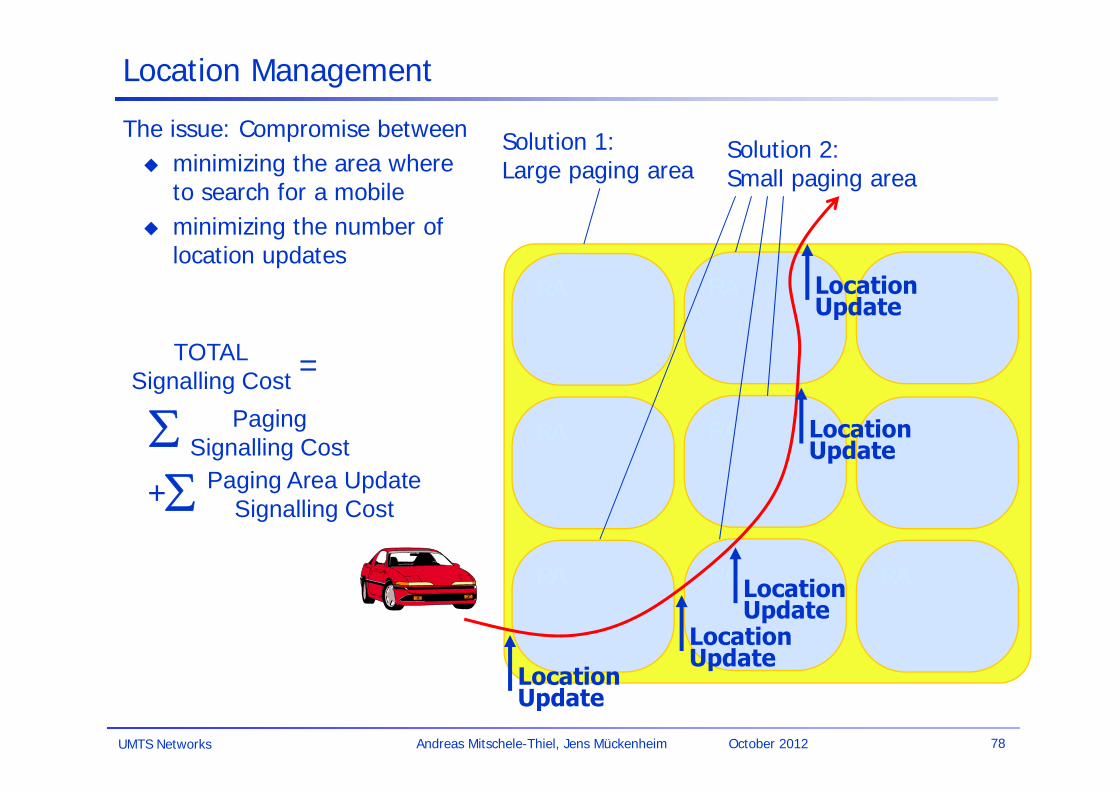
Location Management
The problem: locate a mobile user from the network side (mobile-terminated call)
Two extreme solutions:
Mobile registers with each visited cell(e.g. direct call to the hotel room to reach a person)– signaling traffic to register mobile when cell is changed– network has to maintain location information about each mobile+ low signaling load to page mobile (i.e. in one cell only)
Page mobile using a network- or worldwide broadcast message(e.g. broadcast on TV or radio to contact a person)– heavy signaling load to page the mobile (i.e. in all cells)+ no signaling traffic while mobile is idle
UMTS Networks 78Andreas Mitschele-Thiel, Jens Mückenheim October 2012
RA
RA
RA RA
RA
RA RA
RA
RA
LocationUpdate
LocationUpdate
LocationUpdate
LocationUpdate
LocationUpdate
Location Management
The issue: Compromise between minimizing the area where
to search for a mobile minimizing the number of
location updates
Solution 1:Large paging area
Solution 2:Small paging area
PagingSignalling Cost
Paging Area UpdateSignalling Cost
TOTALSignalling Cost
+
=

UMTS Networks 79Andreas Mitschele-Thiel, Jens Mückenheim October 2012
Handover
The problem:Change the cell while communicating
Reasons for handover: Quality of radio link
deteriorates Communication in other cell
requires less radio resources Supported radius is
exceeded (e.g. Timing advance in GSM)
Overload in current cell Maintenance
Link
qua
lity
Link to cell 1 Link to cell 2 time
cell 1
cell 2
Handover margin (avoid ping-pong effect)
cell 1 cell 2

UMTS Networks 80Andreas Mitschele-Thiel, Jens Mückenheim October 2012
Roaming
The problem: Use a network not subscribed to
Roaming agreement needed between network operators to exchange information concerning: Authentication Authorisation Accounting
Examples of roaming agreements: Use networks abroad Use of T-Mobile network by O2 (E2) subscribers in area with no O2 coverage