MN S 41605 Commissioning - Transport for NSW · This manual contains set to work, testing and...
72
UNCONTROLLED WHEN PRINTED Engineering Manual Signalling and Control Systems MN S 41605 Alstom ETCS Set to Work Testing and Commissioning Version 1.0 Date in Force: 8 March 2019 Manual
Transcript of MN S 41605 Commissioning - Transport for NSW · This manual contains set to work, testing and...

UNCONTROLLED WHEN PRINTED
Engineering Manual Signalling and Control Systems
MN S 41605
Alstom ETCS Set to Work Testing and Commissioning Version 1.0
Date in Force: 8 March 2019
Manual

Sydney Trains Engineering Manual – Signalling and Control Systems Alstom ETCS Set to Work Testing and Commissioning MN S 41605
© Sydney Trains Page 2 of 72 Date in Force: 8 March 2019 UNCONTROLLED WHEN PRINTED Version 1.0 Prepared using: TP ESI 003 V1.8
Approved by:
Stuart Tweedie A/Professional Head Signalling and Control System Engineering System Integrity
Authorised by:
Jonathon McKinnon Engineering Technical Publication Manager System Integrity Unit
Disclaimer This document was prepared for use by Sydney Trains or its contractors only. All Sydney Trains engineering documents are periodically reviewed, and new editions are published, between editions, amendments may also be issued. It is the document user’s sole responsibility to ensure that the copy of the document it is viewing is the current version including any amendments that may have been issued. Errors or omissions in this document should be reported to Sydney Trains. Sydney Trains makes no warranties, express or implied, that compliance with the contents of this document shall be sufficient to ensure safe systems or work or operation. Document control Version Date Author/ Prin. Eng. Summary of change
1.0 8 March 2019 C Darmenia First issue as a Sydney Trains document
Summary of changes from previous version
Summary of change Section Rebranding of TfNSW Alstom ETCS Test & Commissioning Manual v3.0 All

Sydney Trains Engineering Manual – Signalling and Control Systems Alstom ETCS Set to Work Testing and Commissioning MN S 41605
© Sydney Trains Page 3 of 72 Date in Force: 8 March 2019 UNCONTROLLED WHEN PRINTED Version 1.0 Prepared using: TP ESI 003 V1.8
Table of Contents
1 Introduction ............................................................................................................................. 6
2 Scope........................................................................................................................................ 6 2.1 Application ................................................................................................................................. 6
3 Reference documents............................................................................................................. 7
4 Terms and definitions ............................................................................................................. 7
5 Overview .................................................................................................................................. 8
6 Independence of Roles .........................................................................................................12
7 Responsibilities .....................................................................................................................12
8 Tools .......................................................................................................................................12 8.1 BEPT User Profiles .................................................................................................................13
9 Documentation and Certification Preparation ...................................................................13 9.1 Description ..............................................................................................................................14 9.2 ETCS Missions and LEU / Balise Data ...................................................................................15 9.3 ETCS Test Certificates and Testing Checklists ......................................................................15 9.4 LEU Test Certificate ................................................................................................................15 9.5 Balise Group Test Certificate ..................................................................................................16 9.6 Commissioning Work Package ...............................................................................................16
10 Equipment Inspection Checks .............................................................................................17 10.1 Description ..............................................................................................................................17 10.2 Inputs - Applicable Forms and Test Certificates .....................................................................17 10.3 Specific Equipment Inspection Requirements ........................................................................17
10.3.1 LEU and LEU Cabinet Equipment ...........................................................................17 10.3.1.1 Outputs .....................................................................................................18
10.3.2 Balise .......................................................................................................................18 10.3.2.1 Outputs .....................................................................................................20
10.4 Other ETCS Equipment ..........................................................................................................20 10.4.1 ETCS Trackside Junction Box .................................................................................20 10.4.2 Tail Cable .................................................................................................................20 10.4.3 Balise Tail Cable ......................................................................................................20 10.4.4 ETCS Signs .............................................................................................................20 10.4.5 Outputs ....................................................................................................................20
11 ETCS Trackside Equipment – Circuit Test .........................................................................21 11.1 Description ..............................................................................................................................21 11.2 Inputs - Applicable Forms and Test Certificates .....................................................................21 11.3 Activity - Voltage Values .........................................................................................................21 11.4 Activity - LEU Input Current Values ........................................................................................21
11.4.1 Contact Sensing ......................................................................................................21 11.4.2 Current Sensing .......................................................................................................22
11.5 Outputs ....................................................................................................................................22
12 ETCS Setting To Work ..........................................................................................................23

Sydney Trains Engineering Manual – Signalling and Control Systems Alstom ETCS Set to Work Testing and Commissioning MN S 41605
© Sydney Trains Page 4 of 72 Date in Force: 8 March 2019 UNCONTROLLED WHEN PRINTED Version 1.0 Prepared using: TP ESI 003 V1.8
12.1 Description ..............................................................................................................................23 12.2 Inputs - Applicable Forms and Test Certificates .....................................................................23 12.3 Equipment for Function Tests .................................................................................................23 12.4 Activity - Signalling Interface Connection Checks ..................................................................23 12.5 Activity - Power-Up Checks ....................................................................................................23
12.5.1 120Vac Bus .............................................................................................................24 12.5.1.1 Schaffner Filter .........................................................................................24
12.5.2 Toroidal Transformer ...............................................................................................24 12.5.3 MIPS 200 Power Supply ..........................................................................................25
12.6 Outputs ....................................................................................................................................25
13 ETCS Trackside Function Tests ..........................................................................................26 13.1 Description ..............................................................................................................................26 13.2 Inputs - Applicable Forms and Test Certificates .....................................................................26 13.3 Equipment Required for Function Tests .................................................................................26 13.4 Activity - Specific Test Precautions .........................................................................................26 13.5 Activity - LEU Configuration Key Data Checking ....................................................................27 13.6 Activity - Enabling the LEU-Balise Interface ...........................................................................28 13.7 Activity - LEU Telegram Input Correspondence Testing .........................................................29 13.8 Activity - Default Balise Telegram Testing ..............................................................................31 13.9 Activity - ETCS Functional Testing .........................................................................................32
14 Final Adjustment and Commissioning ...............................................................................34 14.1 Activity - Communicating Results ...........................................................................................34 14.2 Activity - Final Documentation ................................................................................................34
Appendix A Applicable ETCS Forms and Test Certificates ...................................................35
Appendix B Part Number Management ....................................................................................46 Alstom Equipment Part Numbers ...........................................................................................................46
LEU .........................................................................................................................................46 Configuration Key ....................................................................................................................47 MIPS 200 ................................................................................................................................47 Balise.......................................................................................................................................47
Appendix C Mission Creation and Data Importing ..................................................................48 Mission Creation by Installation Team ...................................................................................................48
Items Required for Mission Creation .......................................................................................48 BEPT Preparation: ..................................................................................................................49 Importing Balise and LEU data files into the BEPT ................................................................49 BEPT Mission Creation Within the BEPT ...............................................................................50 Additional considerations ........................................................................................................50
Mission Creation by Data Design Team .................................................................................................50 Importing a Mission into the BEPT ..........................................................................................51
Appendix D Programming an LEU Configuration Key ............................................................52 Programming the LEU Configuration Key ..............................................................................................52 Verifying the Programming for an LEU Configuration Key .....................................................................53 Downloading of Programming and Verification Reports ........................................................................55

Sydney Trains Engineering Manual – Signalling and Control Systems Alstom ETCS Set to Work Testing and Commissioning MN S 41605
© Sydney Trains Page 5 of 72 Date in Force: 8 March 2019 UNCONTROLLED WHEN PRINTED Version 1.0 Prepared using: TP ESI 003 V1.8
Appendix E Programming a Balise ...........................................................................................56 Programming the Balise .........................................................................................................................56 Verifying the Programming for a Balise ..................................................................................................58 Downloading Of Programming And Verification Reports: ......................................................................59
Appendix F Erasing Data from a Balise & Unmuting..............................................................60 Erasing a Balise Memory ........................................................................................................................60 14.3 Un-Muting a Balise ..................................................................................................................60
Appendix G Balise Placement ...................................................................................................61 Identification of Balise Placement Position .............................................................................................61
Site Certification Form (SCF) ..................................................................................................61 Measurement Accuracy ..........................................................................................................61
Measurement Procedure ........................................................................................................................61 Measurement Tools ................................................................................................................................63 Key Constraints & Information ................................................................................................................63 Construction Standards Documents: ......................................................................................................63 Other Documents: ..................................................................................................................................64
Appendix H LEU and Balise Validation Activities ...................................................................65 Validating the LEU Configuration Key and Balise Data: ........................................................................65 Actions Required If Validation is Unsuccessful: .....................................................................................65
Appendix I SIGEVENT Record Analysis .................................................................................66 LEU Logs ................................................................................................................................................66 Downloading SigEvent and SysEvent Logs ...........................................................................................66 Interpreting the SigEvent Log .................................................................................................................66 Message ID (MsgID) Interpretation ........................................................................................................68 Notes for Analysing the SigEvent Log ....................................................................................................68 Trackside Logs (LEU) .............................................................................................................................68
Appendix J LEU Precautions ....................................................................................................69 Disconnecting the defective LEU ..........................................................................................................70
Removing the LEU ..................................................................................................................70 Installing a new LEU ...............................................................................................................71 Re-connecting the LEU ...........................................................................................................71 For signals with a current sensing interface only, before powering up an LEU: .....................71 Power-up and visual check .....................................................................................................71 For signals with a current sensing interface only: ...................................................................72
Sydney Trains Engineering Manual – Signalling and Control Systems Alstom ETCS Set to Work Testing and Commissioning MN S 41605
© Sydney Trains Page 6 of 72 Date in Force: 8 March 2019 UNCONTROLLED WHEN PRINTED Version 1.0 Prepared using: TP ESI 003 V1.8
1 Introduction The ATP system deployed on the Sydney Trains Network is an ETCS Level 1 ‘Limited Supervision’ (LS) system providing ceiling speed and distance to go supervision, targeting high risk areas of the network e.g. signals without mechanical train stops, high risk junctions and buffer stops.
This manual contains set to work, testing and commissioning procedures for Alstom ETCS Trackside Equipment. It compliments and is in addition to the inspection and testing requirements specified in the suite of Inspection and Testing of Signalling documents previously known as SPG 0711. As such, the suite of Inspection and Testing of Signalling documents is still the reference for all of the conventional signalling inspection, testing, and commissioning requirements associated with the installation of ETCS.
The ETCS Trackside Equipment Inspection, Testing and Commissioning procedures are described in multiple stages. These procedures follow the general preparation and planning of inspection, testing and commissioning described in the suite of Inspection and Testing of Signalling documents. This document covers equipment inspection, circuit testing, LEU and balise programming, set to work, system functional testing and final adjustment activities for Alstom ETCS Trackside Equipment. All activities are required to be performed in accordance with PR S 40000 Signalling Safeworking Procedures series of documents to ensure the correct and safe operation of the equipment.
These procedures shall be carried out by qualified and authorised personnel who are familiar with the operation of the ETCS equipment. Additional information can be found in the appendices, which give a concise description of the applicable forms and relevant programming procedures.
Note: This set to work procedure was previously known as TMG E1641
2 Scope The procedures described in this document are specific to Alstom ETCS trackside equipment and shall be adopted for the setting to work, inspection, testing and commission of new trackside installations, or for the alteration to existing ETCS trackside installations.
2.1 Application The procedures within this manual take precedence over the suite of Inspection and Testing of Signalling documents. Where a requirement is not referenced in this document, refer to the suite of Inspection and Testing of Signalling documents.
The procedures do NOT cover the following items:
• Detailed setting up and operating procedure for the specialised test equipment particularly the Balise Encoder Programming Tool, this is covered in MN S 41607 BEPT G3 User Manual,
• The inspection and testing of the interface wiring, (this is covered by the suite of Inspection and Testing of Signalling documents).
Note: The Test and Commissioning suite of documents remain the reference for all signalling inspection, testing and commissioning requirements associated with the installation of ETCS.
Sydney Trains Engineering Manual – Signalling and Control Systems Alstom ETCS Set to Work Testing and Commissioning MN S 41605
© Sydney Trains Page 7 of 72 Date in Force: 8 March 2019 UNCONTROLLED WHEN PRINTED Version 1.0 Prepared using: TP ESI 003 V1.8
3 Reference documents This document shall be read in conjunction with the AEO system safety standards, specifications and requirements.
Alstom RailCorp AP1 ETCS Level 1 Trackside T&C Process Description (T-26 A441399, revision B)
Alstom RailCorp AP1 ETCS Level 1 Trackside Programming Process Description (T-26 A441398, revision A)
MN S 40000 Signalling Safeworking Procedures Manual
MN S 41604 Alstom ETCS Trackside Maintenance Manual
MN S 41607 BEPT G3 User Manual
MN S 41611 Micro-COBALT, Micro-coder and ALIS User Manual
MN S 41616 Alstom ETCS User Profiles & Passwords
PR S 45005 ETCS Data Storage and Access
PR S 45006 ATP ETCS Data Design and Process
GL S 45202 Geographical Data for ETCS Level 1
PR S 47110 Inspection & Testing of Signalling
PR S 47111 Roles, Responsibilities and Authorities
M05-500 (series) Virtual Plan Room series of standard drawings for ATP equipment
4 Terms and definitions The following abbreviations and acronyms are used in this document:
ASDO Automatic Selective Door Operation
BMM Big Metal Mass
BEPT Balise and Encoder Programming Tool (Alstom)
CB Circuit Book
CRC Cyclic Redundancy Check (checksum)
COBALT Name of the Alstom LEU platform
CWP Commissioning Work Package
ELD Earth Leakage Detector
ETCS European Train Control System
Firmware The terms Firmware and Software are interchangeable for an LEU, and should not be confused with configuration data
Gold Key A ‘special’ LEU configuration key used to reset the key-pairing configuration
IDF Installed Data Form (part of Circuit Book)
ITF Inspection & Testing Form / Checklist
LEU Lineside Electronic Unit (the generic name for trackside Micro-Coder modules which form an LEU)
Micro-Coder The applicable LEU module from the Alstom Cobalt product range
MIPS200 Power Supply Unit for an Alstom LEU (with capacity for 200ms

Sydney Trains Engineering Manual – Signalling and Control Systems Alstom ETCS Set to Work Testing and Commissioning MN S 41605
© Sydney Trains Page 8 of 72 Date in Force: 8 March 2019 UNCONTROLLED WHEN PRINTED Version 1.0 Prepared using: TP ESI 003 V1.8
uninterrupted supply)
PPT Programming Preparation Tool
SCF Site Certification Form (part of Circuit Book)
SFAIRP So Far As Is Reasonably Practical
SMS Safety Management System (Sydney Trains)
T&C Testing and Commissioning
TC Test Certificate
TfNSW Transport for New South Wales
VPR Virtual Plan Room (a Sydney Trains on-line accessible application within Project Wise web server)
V&V Verification and Validation
5 Overview The overall goal of testing and commissioning of the ATP trackside equipment is to verify that the system is:
• designed and built to (functionally) fulfil its purpose and specified requirements. • physically in accordance with the requirements (designs and specifications), • operates safely in relation to the other associated items of trackside signalling
apparatus and in the presence of a train. The majority of this T&C manual is written around LEU location and its balises however, it is also applicable to the test and commissioning of fixed only balise locations.
To give some context to the trackside LEU installation that will be set to work, inspected, tested and commissioned using this document, a diagram of a typical ETCS LEU trackside installation is shown in Figure 1 below (best viewed in colour).
Standard ETCS Trackside Installation Figure 1
Note: In some locations this new equipment may be placed in an existing trackside
location case or signalling equipment room, or in a new cabinet.
Note *: The filter (Schaffner brand) before the MIPS200 is only needed for LEU's with a current sensing interface.
The objectives of the trackside ETCS installation are:
MIPS200 Micro Coder
Conf Key
120Vac
12Vac
150R
Surge Arrestor
Junction Box
Tail Cable
Fixed Balise
Controlled Balise
Balise Tail
Cable
Cabinet LightingSIG Loc LEU Cabinet Cess 4 Foot
Contact Sensing
Signal LampT
FM
Current Sensing
NewExisting
24Vdc
By-Pass
Filter*
Sydney Trains Engineering Manual – Signalling and Control Systems Alstom ETCS Set to Work Testing and Commissioning MN S 41605
© Sydney Trains Page 9 of 72 Date in Force: 8 March 2019 UNCONTROLLED WHEN PRINTED Version 1.0 Prepared using: TP ESI 003 V1.8
• To allow the LEU to read information from the signalling system (through the interface between existing signalling equipment and the LEU).
• To send information (based on the signalling information read by the LEU) to a balise (through the interface between ETCS LEU and the ETCS balise).
This document contains the following main sections, each of which corresponds to a specific Testing and Commissioning activity:
• Section 10 defines the documentation and certification preparation requirements for the inspection, testing, and commissioning activities for ETCS trackside equipment.
• Section 11 describes the general equipment inspection requirements to be performed on ETCS trackside equipment.
• Section 10 describes the circuit testing requirements to be performed on ETCS trackside equipment.
• Section 13 describes the setting to work activities for ETCS trackside equipment. • Section 14 describes the specific functional testing required for the ETCS
trackside equipment. • Section 15 defines the final adjustment and commissioning activities for ETCS
trackside equipment. • Appendices D (Section 19) and E (Section 20) define the requirements for data
installation (programming) and data testing (verification) of LEU configuration keys and balises. For a project involving new fitments of ETCS equipment, it is most likely that the programming and verification of balise and LEU configuration Key data is undertaken prior to taking the equipment to trackside. The functional tests detailed in Section 15 of this document are undertaken on site once the LEU configuration key is installed in the location case, relay room or ATP cabinet, to ensure that a pre-programmed LEU configuration key is installed at the correct LEU.
The T&C plan processes shall comply with the requirements and recommendations of the suite of Inspection and Testing of Signalling documents.
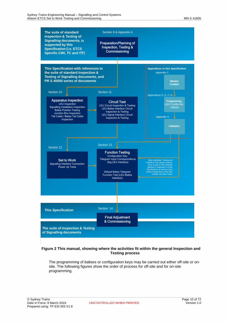
Figure 2 below shows the context of the activities described in this manual with the general inspection & testing procedures and the PR S 40000 series of Safe Working documents.
Sydney Trains Engineering Manual – Signalling and Control Systems Alstom ETCS Set to Work Testing and Commissioning MN S 41605
© Sydney Trains Page 10 of 72 Date in Force: 8 March 2019 UNCONTROLLED WHEN PRINTED Version 1.0 Prepared using: TP ESI 003 V1.8
The suite of standard Inspection & Testing of Signalling documents, is supported by this Specification (i.e. ETCS Specific CWI, TC and ITF)
Section 9 & Appendix A
Preparation/Planning of Inspection, Testing &
Commissioning
This Specification with references to the suite of standard Inspection & Testing of Signalling documents, and PR S 40000 series of documents
Section 10 Section 11
Section 13
Apparatus InspectionLEU Inspection
Signalling Installation InspectionBalise Position TestingJunction Box Inspection
Tail Cable / Balise Tail Cable Inspection
Circuit TestLEU Circuit Inspection & Testing
LEU Balise Interface Circuit Inspection & Testing
LEU Signal Interface Circuit Inspection & Testing
Section 12
Function TestingConfiguration Key
Telegram Input Correspondence(Sig-LEU Interface)
Default Balise TelegramFunction Test (LEU-Balise
Interface)
Data Installation, Testing and Validation loop closure could be
done as part of T&C activities (Section 8 / Appendix H of this Specification) on site by a third
person independent of the Data Installer and Data Tester
This Specification Section 14
Final Adjustment & Commissioning
Appendices to this SpecificationAppendix C
Appendices D, E, F, G
Mission Creation
Programming(LEU Config Key
/ Balise)
Validation
Set to WorkSignalling Interface Connection
Power Up Tests
Appendix H
The suite of Inspection & Testing of Signalling documents
This manual, showing where the activities fit within the general Inspection and Figure 2
Testing process
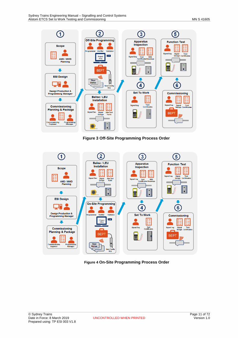
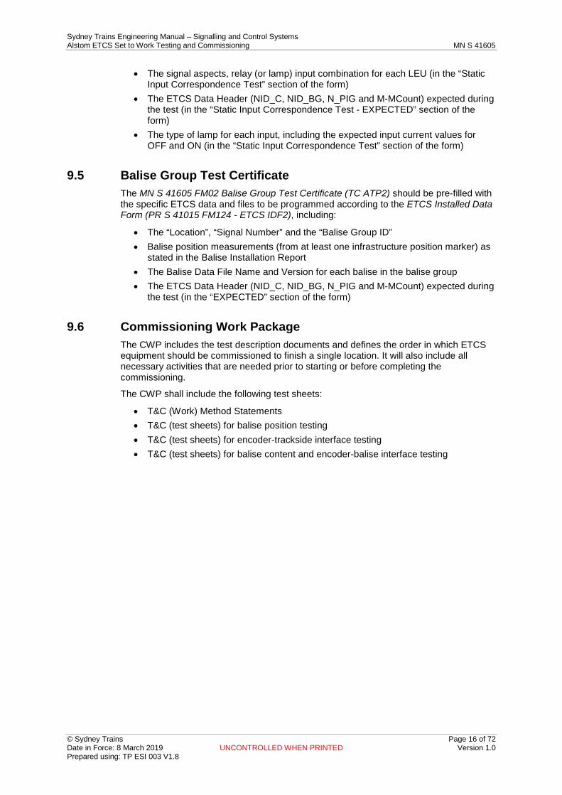
The programming of balises or configuration keys may be carried out either off-site or on-site. The following figures show the order of process for off-site and for on-site programming.
Sydney Trains Engineering Manual – Signalling and Control Systems Alstom ETCS Set to Work Testing and Commissioning MN S 41605
© Sydney Trains Page 11 of 72 Date in Force: 8 March 2019 UNCONTROLLED WHEN PRINTED Version 1.0 Prepared using: TP ESI 003 V1.8
Off-Site Programming Process Order Figure 3
On-Site Programming Process Order Figure 4

Sydney Trains Engineering Manual – Signalling and Control Systems Alstom ETCS Set to Work Testing and Commissioning MN S 41605
© Sydney Trains Page 12 of 72 Date in Force: 8 March 2019 UNCONTROLLED WHEN PRINTED Version 1.0 Prepared using: TP ESI 003 V1.8
6 Independence of Roles Alstom safety related exported constraints require that the Programmer, the Verifier and the Validator shall be three different people (BEPT User Manual [3]).
An individual shall not carry out T&C if they have participated in any of the ETCS installation construction activities (Roles, Responsibilities and Authorities ASA SPG0711.1). The following duty holders shall not have participated in any of the ETCS installation construction activities:
• Commissioning Engineer • Tester in Charge • Tester
7 Responsibilities The Commissioning Engineer is responsible for:
• Implementing a plan that defines all T&C activities to be carried out as part of the works,
• Preparing/compiling the Commissioning Work Package, and • Registering the Commissioning Work Package final results. Refer to Section 9.6
and 14.2 for further duties. The Tester In Charge is responsible for the testing and commissioning activities which shall validate that the system satisfies the requirements and checking that the Commissioning Work Package is complete and includes all applicable:
• Work Instructions, • Work Method Statements, • Inspection Forms and Test Certificates, • Circuit Book(s), • Signalling Plan(s), • Standard Drawings (M05-500 series) applicable to the installation, • List of data configuration file names (to be downloaded from the Sydney Trains
intranet). Note: If a paper or digital copy of the relevant standard drawings are not included with the Work Package:
• The Commissioning Engineer must include a list of the applicable M05-500 series drawings in the Work package, and
• The Tester In Charge and Test & Commissioning Engineers must have direct access to those drawings via the VPR from the test site.
As per the SMS standard safe working requirements (Network Rules and Network Procedures), a Protection Officer must be provided to ensure that the appropriate level of protection on site is provided.
8 Tools The following tools are required for ETCS Test and Commissioning:
• Multimeter (approved and calibrated) - for voltage and current measurements (True RMS a.c. and d.c.). A non-contact type current clamp meter will also be required for use with current sensing locations suitable to measure LED lights. If the measurement is at the threshold of reading using the clamp meter, use a multi-meter for confirmation.
• BEPT kit. • Generic tools such as screwdrivers.

Sydney Trains Engineering Manual – Signalling and Control Systems Alstom ETCS Set to Work Testing and Commissioning MN S 41605
© Sydney Trains Page 13 of 72 Date in Force: 8 March 2019 UNCONTROLLED WHEN PRINTED Version 1.0 Prepared using: TP ESI 003 V1.8
8.1 BEPT User Profiles Several roles (actors) are required in order to perform the Programming and T&C activities. Independence between different roles is required for process integrity, and hence different User Profiles are created within the BEPT with different menus and different levels of access rights appropriate for the role.
Only authorised and trained persons may use the BEPT.
Refer to MN S 41616 Alstom ETCS User Profiles & Passwords for User Profiles and Logins available.
Several roles are required in order to carry out ETCS data programming and verification activities. Independence between different roles is required for process integrity, and hence different user profiles are created within the BEPT with different menus and different levels of access rights appropriate for the role.
BEPT users shall log in to the BEPT as per the authority level relevant to the task being undertaken.
The following User Profiles and Logins are available:
User Profile Description Login
Programming Manager
Primarily to be used for the mission creation process. This could be undertaken by either the ETCS data design team or the ETCS installation team. The Profile is also used for importing missions, setting the BEPT clock and setting the LEU IP address fields.
ertms
Programmer Used during the programming of a balise or LEU configuration key.
prog
Verifier Used during the testing of the data programmed into a balise or LEU configuration key. Also described as the ETCS Verifier.
ver
Validator Although this is not a BEPT login, this person plays a key role in the validation of the data programmed into a balise or LEU configuration key. Also described as the ETCS Validator or ETCS data Validator.
N/A
Eraser Used when erasing balise data. Note: This function cannot be used to erase LEU data. A Gold Key is required to de-pair an LEU from its Configuration key.
eraser
Table 1 BEPT User Profiles and Logins
Note: Refer to the MN S 41604 Alstom ETCS Trackside Maintenance Manual for details of setting up the BEPT.
9 Documentation and Certification Preparation The testing and commissioning Work Package should be prepared in advance, the objective being to help the testing and commissioning (T&C) team to:
• maintain documentation on a regular and consistent basis • reduce opportunities for errors • reduce time in the field, and most importantly • enable the team to focus on the outcomes to be achieved.

Sydney Trains Engineering Manual – Signalling and Control Systems Alstom ETCS Set to Work Testing and Commissioning MN S 41605
© Sydney Trains Page 14 of 72 Date in Force: 8 March 2019 UNCONTROLLED WHEN PRINTED Version 1.0 Prepared using: TP ESI 003 V1.8
A complete set of approved and independently checked documents for the proposed testing and commissioning (T&C) work should be prepared in advance of the data installation and testing activities.
T&C documentation:
• ensures that the equipment fulfils the specified requirements and the documentation is a true representation of deliverables of the commissioning of the project.
• ensures that the equipment is SFAIRP safe for use. • that will be included in the deliverables is normally shown in a table format with
responsibilities of individual team members who will prepare, review, and accept the results and documentation.
• assists with communicating the T&C status to the wider project team.
9.1 Description The Commissioning Engineer is responsible for the preparation of the Commissioning Work Package documentation (i.e. the test description package).
The Commissioning Engineer is responsible for the pre-filling out the Test Certificates with the expected CRC (first four digits only). The half CRC is obtained from the release notes documentation.
All reports are to be part of the Commissioning Engineers work package.
The following set of documents forms the Commissioning Work Package, and will typically consist of:
• Signalling Plan • ETCS Balise and LEU Tables • PR S 41015 FM124 ETCS IDF2 - ETCS Installed Data Forms (Balise) • PR S 41015 FM125 ETCS IDF1 - ETCS Installed Data Forms (LEU Configuration
Key) • Circuit Books containing IDF's and SCF's • Including:
For each LEU cabinet or existing location case / relay rack containing LEUs:
– MN S 41605 FM05 - ITF ATP1 – LEU Cabinet Inspection and Testing Checklist – MN S 41605 FM03 - TC ATP3 – LEU Cabinet / Location Equipment Serial
Number Register – MN S 41605 FM04 - TC ATP4 – ETCS Cabinet Power Supply Test Certificate For each Signal where an LEU is installed:
– MN S 41605 FM01 - TC ATP1 – LEU Test Certificate. For each balise group:
– MN S 41605 FM02 - TC ATP2 – Balise Group Test Certificate – MN S 41605 FM06 - ITF ATP2 – Balise Group Inspection and Testing Checklist – Commissioning Work Package (CWP) – ETCS missions, LEU and balise; data

Sydney Trains Engineering Manual – Signalling and Control Systems Alstom ETCS Set to Work Testing and Commissioning MN S 41605
© Sydney Trains Page 15 of 72 Date in Force: 8 March 2019 UNCONTROLLED WHEN PRINTED Version 1.0 Prepared using: TP ESI 003 V1.8
9.2 ETCS Missions and LEU / Balise Data The term 'mission' refers to a data file containing a consolidated set of pre-defined data programming or verification activities, pre-prepared by the Sydney Trains (RIM) competent ETCS data design team (design office activity) ready for downloading from the RIM’s secure data network, the Virtual Plan Room (ProjectWise), by field maintenance staff.
A mission is executed by the BEPT user, and prevents errors in the data programming and verification by limiting these activities to those which are pre-defined, and associated with the correct balise or LEU data.
Mission files are stored alongside the data files for each balise or LEU configuration key for which they apply, as well as the associated Balise and LEU Installed Data Forms (PR S 41015 FM125 [ETCS IDF1] and PR S 41015 FM124 [ETCS IDF2]), and are accessed by the maintenance staff for importing into the BEPT, using an approved USB memory stick.
One data programming mission and one data verification mission is required for each LEU or balise.
For initial installation and some major works activities, missions can be:
• Created inside the BEPT by the ETCS Programmer (see Note 1 below) once the LEU / balise data file are issued;
• Pre-loaded into the BEPT by the ETCS Data Design team, along with the LEU / balise data files; or
• Created by the ETCS Data Design team as pre-prepared (.xml) files and imported into the BEPT by the ETCS Programmer using the Programming Manager profile ('ertms'), along with the LEU / balise data files.
The latter option is preferred, as it reduces instances of errors in the mission creation process.
Note 1: The Programmer must first log in under the Programming Manager profile ('ertms') in order to import missions into the BEPT. Once the missions have been loaded into the BEPT, the Programmer shall log out of 'ertms'.
9.3 ETCS Test Certificates and Testing Checklists The specific forms including headers and Test Certificates are prior prepared for the equipment detailed on the ETCS Installed Data Form PR S 41015 FM124 / FM125 (ETCS IDF2/1).
Other than Project details and cabinet / location names, Installation and Test Checklists MN S 41605 FM05 & FM06 (ITF ATP1 and ITF ATP2), and Test Certificates MN S 41605 FM03 & FM04 (TC ATP3 and TC ATP4) do not need any specific data to be added.
Refer to Section15 Appendix A - Applicable ETCS Forms and Test Certificates for example checklist forms and test certificates. These forms and test certificates can be downloaded from the Sydney Trains intranet.
9.4 LEU Test Certificate The MN S 41605 FM01 LEU Test Certificate (TC ATP1) should be pre-filled with the specific ETCS data and files to be programmed according to the relevant ETCS Installed Data Form (PR S 41015 FM125 - ETCS IDF1), including:
• The “Signal Box / Interlocking”, “Line Name” and the “Signal” • The LEU Data File Name and Version for each LEU associated with the signal (in
the “Configuration Key and ETCS Data Version” section of the form)
Sydney Trains Engineering Manual – Signalling and Control Systems Alstom ETCS Set to Work Testing and Commissioning MN S 41605
© Sydney Trains Page 16 of 72 Date in Force: 8 March 2019 UNCONTROLLED WHEN PRINTED Version 1.0 Prepared using: TP ESI 003 V1.8
• The signal aspects, relay (or lamp) input combination for each LEU (in the “Static Input Correspondence Test” section of the form)
• The ETCS Data Header (NID_C, NID_BG, N_PIG and M-MCount) expected during the test (in the “Static Input Correspondence Test - EXPECTED” section of the form)
• The type of lamp for each input, including the expected input current values for OFF and ON (in the “Static Input Correspondence Test” section of the form)
9.5 Balise Group Test Certificate The MN S 41605 FM02 Balise Group Test Certificate (TC ATP2) should be pre-filled with the specific ETCS data and files to be programmed according to the ETCS Installed Data Form (PR S 41015 FM124 - ETCS IDF2), including:
• The “Location”, “Signal Number” and the “Balise Group ID” • Balise position measurements (from at least one infrastructure position marker) as
stated in the Balise Installation Report • The Balise Data File Name and Version for each balise in the balise group • The ETCS Data Header (NID_C, NID_BG, N_PIG and M-MCount) expected during
the test (in the “EXPECTED” section of the form)
9.6 Commissioning Work Package The CWP includes the test description documents and defines the order in which ETCS equipment should be commissioned to finish a single location. It will also include all necessary activities that are needed prior to starting or before completing the commissioning.
The CWP shall include the following test sheets:
• T&C (Work) Method Statements • T&C (test sheets) for balise position testing • T&C (test sheets) for encoder-trackside interface testing • T&C (test sheets) for balise content and encoder-balise interface testing

Sydney Trains Engineering Manual – Signalling and Control Systems Alstom ETCS Set to Work Testing and Commissioning MN S 41605
© Sydney Trains Page 17 of 72 Date in Force: 8 March 2019 UNCONTROLLED WHEN PRINTED Version 1.0 Prepared using: TP ESI 003 V1.8
10 Equipment Inspection Checks
10.1 Description This section describes the general equipment inspection activities to be carried out by the T&C team. It covers the visual check for LEU cabinets, LEUs (and associated interface equipment), power supplies, balise cables and balises.
The Tester In Charge shall be responsible for verifying that the:
• layout of equipment conforms to the latest approved design documentation, plans, drawings and standard specifications
• The equipment is of the correct quantity, rating, type, model, brand, colour, labelling and quality of workmanship
The Tester In Charge shall be responsible for filling out and signing of the following documents:
• applicable Checklist Forms • applicable Test Certificates • documenting any as-built changes on the applicable documents
The Tester In Charge shall be responsible for checking that the T&C has been completed in accordance with the requirements of the suite of Inspection and Testing of Signalling documents and in accordance with this procedure.
10.2 Inputs - Applicable Forms and Test Certificates The results of specific equipment inspections shall be recorded using the following Inspection and Testing Checklists (shown in Appendix A):
• MN S 41605 FM05 - ITF ATP1 – LEU Cabinet Inspection and Testing Checklist • MN S 41605 FM06 - ITF ATP2 – Balise Group Inspection and Testing Checklist
The following specific ETCS Test Certificates shall also be completed:
• MN S 41605 FM01 - TC ATP1 – LEU Test Certificate (for all LEUs at one signal) • MN S 41605 FM02 - TC ATP2 – Balise Group Test Certificate • MN S 41605 FM03 - TC ATP3 – LEU Cabinet / Location Equipment Serial Number
Register • MN S 41605 FM04 - TC ATP4 – ATP Location Power Supply Test Certificate.
10.3 Specific Equipment Inspection Requirements
10.3.1 LEU and LEU Cabinet Equipment The following checks shall be undertaken by the test and commissioning team as part of the setting to work of the LEU and the LEU cabinet equipment, location case or relay room equipment:
1. LEU Power Supply: Check that the LEU Power Supply is correct, and is labelled correctly according to the Circuit Book
2. LEU: Check that the LEU is correct, and is labelled correctly according to the Circuit Book
3. LEU ID: Check that the LEU ID plate is the correct type and format according to M05-549 construction drawing
4. LEU Configuration Key: Check that the LEU configuration key is correctly secured. Measure and record the length of the LEU configuration key attachment tether, and check that is it not possible to connect the LEU configuration key to an
Sydney Trains Engineering Manual – Signalling and Control Systems Alstom ETCS Set to Work Testing and Commissioning MN S 41605
© Sydney Trains Page 18 of 72 Date in Force: 8 March 2019 UNCONTROLLED WHEN PRINTED Version 1.0 Prepared using: TP ESI 003 V1.8
adjacent LEU in the same cabinet or equipment rack). Complete the LEU Test Certificate (MN S 41605 FM01 - TC ATP1) with “OK” or “Not OK”
5. LEU Vital Plug Coupler: Check that the LEU Vital Plug Coupler(s) are correctly secured and labelled (according to drawing M05-516), and that it is not possible to connect a LEU Vital Plug Coupler to an adjacent LEU in the same cabinet or equipment rack. Complete the LEU Test Certificate (MN S 41605 FM01 - TC ATP1) with “OK” or “Not OK”
6. General: Check compliance to construction specifications and specific construction drawings. The specific drawings references are included in the M05-500 series drawings
7. Serial Numbers: For each specific item of ETCS trackside equipment (LEUs, LEU Power Supplies and Ethernet Switch (where fitted) in the cabinet, record the following in the LEU Cabinet / Location Equipment Serial Number Register (MN S 41605 FM03 - TC ATP3): – Associated signal name and LEU (ABC); – Part number – Serial Number (if applicable) – Hardware Revision – Firmware Revision (if applicable) – Manufacture date (if applicable)
10.3.1.1 Outputs The Tester in Charge shall ensure that the following documents are filled out, signed and issued to the Commissioning Engineer:
• MN S 41605 FM05 - ITF ATP1 Checklist Form • MN S 41605 FM01 - TC ATP1 Test Certificate • MN S 41605 FM03 - TC ATP3 Test Certificate • MN S 41605 FM04 - TC ATP4 Test Certificate • As-built mark-ups to Signalling Plan or Circuit Book
Note: IDF's are part of Circuit Book and are to be signed.
10.3.2 Balise The following checks shall be undertaken by the test and commissioning team as part of the setting to work of the balise:
1. Balise: Check that the balise is the correct type, according to the M05-500 series of standard drawings
2. Balise Installation: Check the following:
– For a balise mounted on-sleeper using a Vortok beam check that the balise installation is compliant with drawing M05-569 and is installed in accordance with the Vortok Installation Manual
– For a balises mounted between sleepers using a Vortok universal (clamp) beam, check that the balise is installed in accordance with the Vortok Installation Manual
– For a balise directly fixed to the track check that the balise installation is compliant with drawings M05-501 or M05-502 (depending on the sleeper type)
– For a balise mounted between guard rails using a longitudinal mounting plate, check that the balise is compliant with drawing M05-558
Sydney Trains Engineering Manual – Signalling and Control Systems Alstom ETCS Set to Work Testing and Commissioning MN S 41605
© Sydney Trains Page 19 of 72 Date in Force: 8 March 2019 UNCONTROLLED WHEN PRINTED Version 1.0 Prepared using: TP ESI 003 V1.8
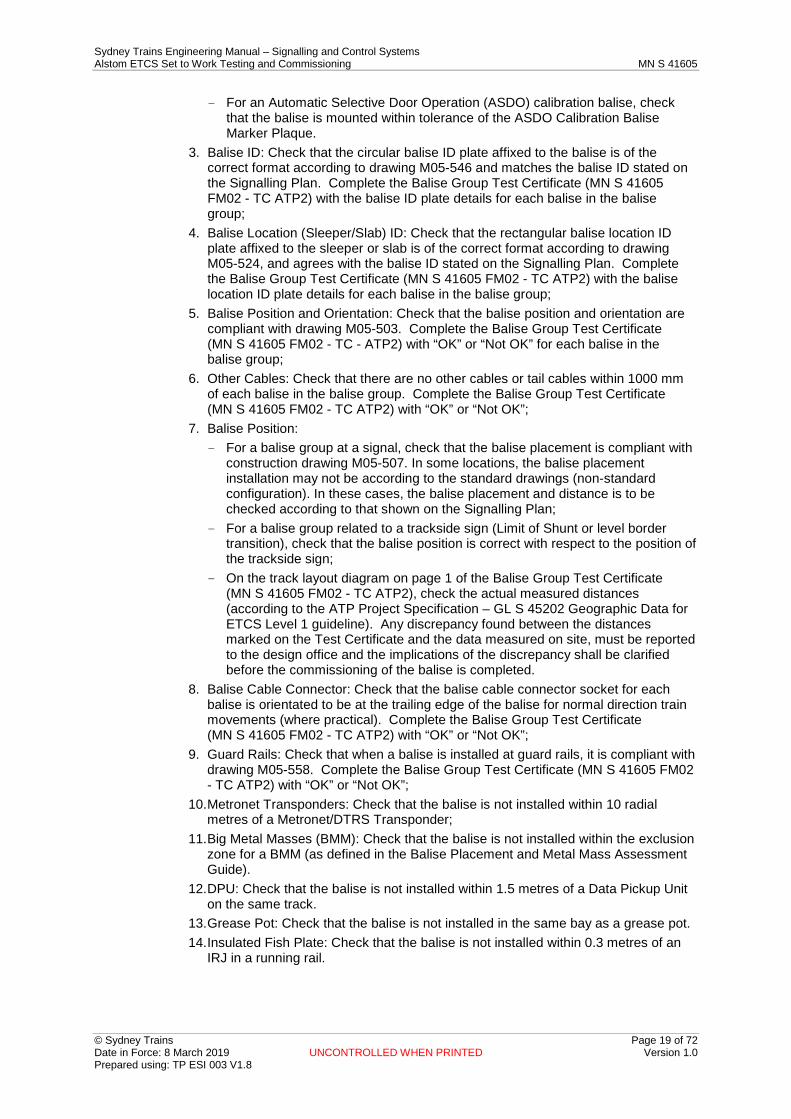
– For an Automatic Selective Door Operation (ASDO) calibration balise, check that the balise is mounted within tolerance of the ASDO Calibration Balise Marker Plaque.
3. Balise ID: Check that the circular balise ID plate affixed to the balise is of the correct format according to drawing M05-546 and matches the balise ID stated on the Signalling Plan. Complete the Balise Group Test Certificate (MN S 41605 FM02 - TC ATP2) with the balise ID plate details for each balise in the balise group;
4. Balise Location (Sleeper/Slab) ID: Check that the rectangular balise location ID plate affixed to the sleeper or slab is of the correct format according to drawing M05-524, and agrees with the balise ID stated on the Signalling Plan. Complete the Balise Group Test Certificate (MN S 41605 FM02 - TC ATP2) with the balise location ID plate details for each balise in the balise group;
5. Balise Position and Orientation: Check that the balise position and orientation are compliant with drawing M05-503. Complete the Balise Group Test Certificate (MN S 41605 FM02 - TC - ATP2) with “OK” or “Not OK” for each balise in the balise group;
6. Other Cables: Check that there are no other cables or tail cables within 1000 mm of each balise in the balise group. Complete the Balise Group Test Certificate (MN S 41605 FM02 - TC ATP2) with “OK” or “Not OK”;
7. Balise Position: – For a balise group at a signal, check that the balise placement is compliant with
construction drawing M05-507. In some locations, the balise placement installation may not be according to the standard drawings (non-standard configuration). In these cases, the balise placement and distance is to be checked according to that shown on the Signalling Plan;
– For a balise group related to a trackside sign (Limit of Shunt or level border transition), check that the balise position is correct with respect to the position of the trackside sign;
– On the track layout diagram on page 1 of the Balise Group Test Certificate (MN S 41605 FM02 - TC ATP2), check the actual measured distances (according to the ATP Project Specification – GL S 45202 Geographic Data for ETCS Level 1 guideline). Any discrepancy found between the distances marked on the Test Certificate and the data measured on site, must be reported to the design office and the implications of the discrepancy shall be clarified before the commissioning of the balise is completed.
8. Balise Cable Connector: Check that the balise cable connector socket for each balise is orientated to be at the trailing edge of the balise for normal direction train movements (where practical). Complete the Balise Group Test Certificate (MN S 41605 FM02 - TC ATP2) with “OK” or “Not OK”;
9. Guard Rails: Check that when a balise is installed at guard rails, it is compliant with drawing M05-558. Complete the Balise Group Test Certificate (MN S 41605 FM02 - TC ATP2) with “OK” or “Not OK”;
10. Metronet Transponders: Check that the balise is not installed within 10 radial metres of a Metronet/DTRS Transponder;
11. Big Metal Masses (BMM): Check that the balise is not installed within the exclusion zone for a BMM (as defined in the Balise Placement and Metal Mass Assessment Guide).
12. DPU: Check that the balise is not installed within 1.5 metres of a Data Pickup Unit on the same track.
13. Grease Pot: Check that the balise is not installed in the same bay as a grease pot. 14. Insulated Fish Plate: Check that the balise is not installed within 0.3 metres of an
IRJ in a running rail.
Sydney Trains Engineering Manual – Signalling and Control Systems Alstom ETCS Set to Work Testing and Commissioning MN S 41605
© Sydney Trains Page 20 of 72 Date in Force: 8 March 2019 UNCONTROLLED WHEN PRINTED Version 1.0 Prepared using: TP ESI 003 V1.8
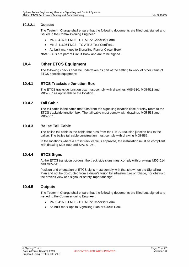
10.3.2.1 Outputs The Tester in Charge shall ensure that the following documents are filled out, signed and issued to the Commissioning Engineer:
• MN S 41605 FM06 - ITF ATP2 Checklist Form • MN S 41605 FM02 - TC ATP2 Test Certificate • As-built mark-ups to Signalling Plan or Circuit Book
Note: IDF's are part of Circuit Book and are to be signed.
10.4 Other ETCS Equipment The following checks shall be undertaken as part of the setting to work of other items of ETCS specific equipment:
10.4.1 ETCS Trackside Junction Box The ETCS trackside junction box must comply with drawings M05-510, M05-511 and M05-567 as applicable to the location.
10.4.2 Tail Cable The tail cable is the cable that runs from the signalling location case or relay room to the ETCS trackside junction box. The tail cable must comply with drawings M05-538 and M05-557.
10.4.3 Balise Tail Cable The balise tail cable is the cable that runs from the ETCS trackside junction box to the balise. The balise tail cable construction must comply with drawing M05-552.
In the locations where a cross track cable is approved, the installation must be compliant with drawing M05-509 and SPG 0705.
10.4.4 ETCS Signs At the ETCS transition borders, the track side signs must comply with drawings M05-514 and M05-515.
Position and orientation of ETCS signs must comply with that shown on the Signalling Plan and not be obstructed from a driver's vision by infrastructure or foliage, nor obstruct the driver's view of a signal or safety important sign.
10.4.5 Outputs The Tester in Charge shall ensure that the following documents are filled out, signed and issued to the Commissioning Engineer:
• MN S 41605 FM06 - ITF ATP2 Checklist Form • As-built mark-ups to Signalling Plan or Circuit Book

Sydney Trains Engineering Manual – Signalling and Control Systems Alstom ETCS Set to Work Testing and Commissioning MN S 41605
© Sydney Trains Page 21 of 72 Date in Force: 8 March 2019 UNCONTROLLED WHEN PRINTED Version 1.0 Prepared using: TP ESI 003 V1.8
11 ETCS Trackside Equipment – Circuit Test
11.1 Description Tests for Continuity, Wire Count, Null Count, Insulation Test and Circuit Function Test shall be performed as per the suite of Inspection and Testing of Signalling documents for the interface wiring related to the ETCS Trackside Equipment.
The Tester In Charge is responsible for checking that the T&C has been completed in accordance with the requirements of the suite of Inspection and Testing of Signalling documents and in accordance with this procedure.
Notes:
• Current sensing LEU wiring is considered vital (i.e. some faults could cause an unsafe outcome of the signalling system).
• Contact sensing LEU wiring is considered non vital (i.e. the circuits should not affect the safe operation of the signalling system).
11.2 Inputs - Applicable Forms and Test Certificates The results of specific circuit test activities as described in this manual are recorded in the following forms using the corresponding Inspection and Testing Checklists:
• MN S 41605 FM05 - ITF ATP1 – LEU Cabinet Inspection and Testing Checklist • MN S 41605 FM06 - ITF ATP2 – Balise Group Inspection and Testing Checklist
11.3 Activity - Voltage Values Voltage ranges are described in the following table:
Bus Description Expected Range
Nominal 120 V a.c. signalling supply bus 96 / 132 V a.c.
Nominal 12 V a.c. (Transformer output) 10.6/15.7 V a.c. (8.5:1 ±5%)
Nominal 24 V d.c. (PSU output) 24(±5%) V d.c.
Table 2 Power Supplies Nominal Voltage
11.4 Activity - LEU Input Current Values
11.4.1 Contact Sensing Contact Sensing inputs use a 150 Ohm resistor in series with the circuit and are powered by the 12 V a.c. toroidal transformer output.
Expected ON state current range is 68 mA to 111 mA.
Threshold for the OFF state is 10 mA.
Threshold for the ON state is 51 mA.
Measure each input to the LEU to confirm that the current draw is within the correct range above, for OFF and for ON states.
If current is outside the range for OFF and ON state, check:
• transformer input and output voltage • transformer windings to ensure that they are sharing the load (i.e. both windings
are functional),
Sydney Trains Engineering Manual – Signalling and Control Systems Alstom ETCS Set to Work Testing and Commissioning MN S 41605
© Sydney Trains Page 22 of 72 Date in Force: 8 March 2019 UNCONTROLLED WHEN PRINTED Version 1.0 Prepared using: TP ESI 003 V1.8
• relay contact for high resistance • resistor for high resistance • wiring for faults, and • connections for high resistance
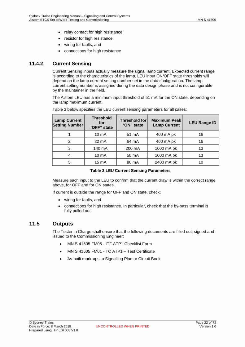
11.4.2 Current Sensing Current Sensing inputs actually measure the signal lamp current. Expected current range is according to the characteristics of the lamp. LEU input ON/OFF state thresholds will depend on the lamp current setting number set in the data configuration. The lamp current setting number is assigned during the data design phase and is not configurable by the maintainer in the field.
The Alstom LEU has a minimum input threshold of 51 mA for the ON state, depending on the lamp maximum current.
Table 3 below specifies the LEU current sensing parameters for all cases:
Lamp Current Setting Number
Threshold for
‘OFF” state Threshold for
‘ON” state Maximum Peak Lamp Current LEU Range ID
1 10 mA 51 mA 400 mA pk 16 2 22 mA 64 mA 400 mA pk 16 3 140 mA 200 mA 1000 mA pk 13 4 10 mA 58 mA 1000 mA pk 13 5 15 mA 80 mA 2400 mA pk 10
Table 3 LEU Current Sensing Parameters
Measure each input to the LEU to confirm that the current draw is within the correct range above, for OFF and for ON states.
If current is outside the range for OFF and ON state, check:
• wiring for faults, and • connections for high resistance. In particular, check that the by-pass terminal is
fully pulled out.
11.5 Outputs The Tester in Charge shall ensure that the following documents are filled out, signed and issued to the Commissioning Engineer:
• MN S 41605 FM05 - ITF ATP1 Checklist Form
• MN S 41605 FM01 - TC ATP1 – Test Certificate
• As-built mark-ups to Signalling Plan or Circuit Book
Sydney Trains Engineering Manual – Signalling and Control Systems Alstom ETCS Set to Work Testing and Commissioning MN S 41605
© Sydney Trains Page 23 of 72 Date in Force: 8 March 2019 UNCONTROLLED WHEN PRINTED Version 1.0 Prepared using: TP ESI 003 V1.8
12 ETCS Setting To Work
12.1 Description This section describes the set to work activities to be carried out prior to the ETCS trackside function testing activities.
The Tester In Charge is responsible for setting to work and filling out and signing the following documents:
• applicable Checklist Forms • applicable Test Certificates • documenting any as-built changes on the applicable documents
The Tester In Charge is responsible for checking that the T&C function testing has been completed in accordance with the requirements of SPG 0711 and in accordance with this procedure.
12.2 Inputs - Applicable Forms and Test Certificates Results of specific Set-to-Work activities described in this manual are recorded as per the tailored Work Instructions, which are developed from the Inspection and Testing Checklists listed below:
• MN S 41605 FM05 - ITF ATP1 – LEU Cabinet Inspection and Testing Checklist The following specific Test Certificate is also completed:
• MN S 41605 FM04 - TC ATP4 – ETCS Cabinet Power Supply Test Certificate
12.3 Equipment for Function Tests The minimum equipment required by the set-to-work team is listed below:
• Multimeter (approved and calibrated) - for voltage and current measurements (True RMS a.c. and d.c.). A current clamp meter will also be required for use with current sensing locations.
12.4 Activity - Signalling Interface Connection Checks Connect the LEU cabinet to existing signalling system, in accordance with the provisions of PR S 40000 Signalling Safeworking Procedures manual.
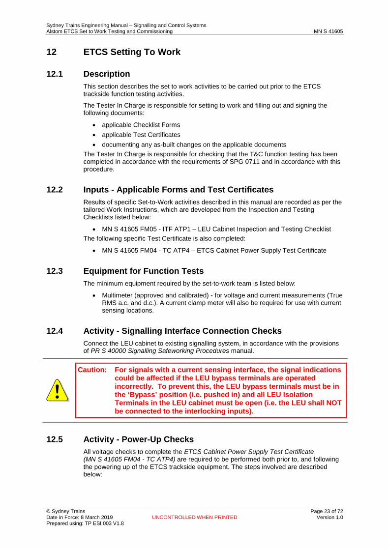
Caution: For signals with a current sensing interface, the signal indications could be affected if the LEU bypass terminals are operated incorrectly. To prevent this, the LEU bypass terminals must be in the ‘Bypass’ position (i.e. pushed in) and all LEU Isolation Terminals in the LEU cabinet must be open (i.e. the LEU shall NOT be connected to the interlocking inputs).
12.5 Activity - Power-Up Checks All voltage checks to complete the ETCS Cabinet Power Supply Test Certificate (MN S 41605 FM04 - TC ATP4) are required to be performed both prior to, and following the powering up of the ETCS trackside equipment. The steps involved are described below:
Sydney Trains Engineering Manual – Signalling and Control Systems Alstom ETCS Set to Work Testing and Commissioning MN S 41605
© Sydney Trains Page 24 of 72 Date in Force: 8 March 2019 UNCONTROLLED WHEN PRINTED Version 1.0 Prepared using: TP ESI 003 V1.8
12.5.1 120Vac Bus Measure the 120V without any load in the LEU cabinet. If that voltage is within the acceptable range, power up the LEU in accordance with the procedures in Appendix J (LEU Precautions).
Check voltage at the cabinet input terminals and voltage at the input to each MIPS200 and record in the ETCS Cabinet Power Supply Test Certificate (MN S 41605 FM04 - TC ATP4).
12.5.1.1 Schaffner Filter For current sensing, an EMC filter is fitted at the MIPS200 input.
Refer to the Maintenance Manual (PR S 41064) for replacement procedure.
Caution: Care needs to be taken to ensure that a replacement noise filter module is connected the correct way around. It is physically possible to install the module the wrong way around and the MIPS200 will still work, but in this case the filter module would not function properly. Standard drawing M05-563 shows the correct orientation.
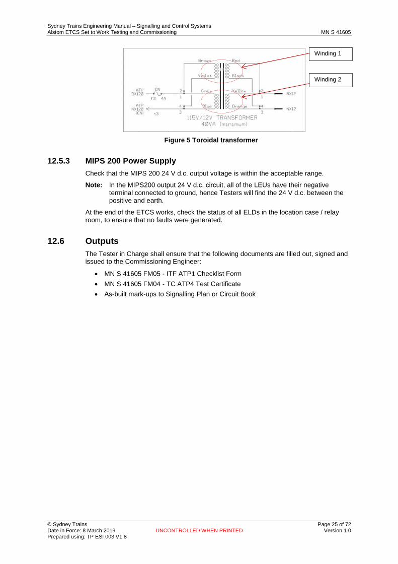
12.5.2 Toroidal Transformer For contact sensing, check that both transformer coils are operating correctly by comparing the current and voltage balance of both windings on the secondary side (12V nominal), and confirm that they are balanced within 10%.
Toroidal Transformer Test Process:
• Test 1 - Using a current clamp meter test winding 1 by clamping over the Red secondary wire of the transformer and recording the current in the test form MN S 41605 FM04 - TC ATP4.
• Test 2 - Using a current clamp meter test winding 2 by clamping over the Yellow secondary wire of the transformer and recording the current in the test form MN S 41605 FM04 - TC ATP4.
Note: The results from test 1 and 2 should be equal within 10% of each other.
• Test 3 - Using a current clamp meter test the transformer load by clamping over the BX12 terminal feed cable past the transformer secondary termination and record the current in the test form MN S 41605 FM04 - TC ATP4.
Note: The output from test 3 should be the approximate sum of test 1 & 2.
• Test 4 - Using a meter approved to measure voltage, open the four isolating terminals on the transformer secondaries. Measure the transformer secondaries open circuit voltage at winding 1 (red and black wires) then winding 2 (yellow and orange wires) and record the results in the test form MN S 41605 FM04 - TC ATP4. The results should be within 10% of each other.
• After testing, close the isolating terminals.
Sydney Trains Engineering Manual – Signalling and Control Systems Alstom ETCS Set to Work Testing and Commissioning MN S 41605
© Sydney Trains Page 25 of 72 Date in Force: 8 March 2019 UNCONTROLLED WHEN PRINTED Version 1.0 Prepared using: TP ESI 003 V1.8
Toroidal transformer Figure 5
12.5.3 MIPS 200 Power Supply Check that the MIPS 200 24 V d.c. output voltage is within the acceptable range.
Note: In the MIPS200 output 24 V d.c. circuit, all of the LEUs have their negative terminal connected to ground, hence Testers will find the 24 V d.c. between the positive and earth.
At the end of the ETCS works, check the status of all ELDs in the location case / relay room, to ensure that no faults were generated.
12.6 Outputs The Tester in Charge shall ensure that the following documents are filled out, signed and issued to the Commissioning Engineer:
• MN S 41605 FM05 - ITF ATP1 Checklist Form • MN S 41605 FM04 - TC ATP4 Test Certificate • As-built mark-ups to Signalling Plan or Circuit Book
Winding 1
Winding 2 0

Sydney Trains Engineering Manual – Signalling and Control Systems Alstom ETCS Set to Work Testing and Commissioning MN S 41605
© Sydney Trains Page 26 of 72 Date in Force: 8 March 2019 UNCONTROLLED WHEN PRINTED Version 1.0 Prepared using: TP ESI 003 V1.8
13 ETCS Trackside Function Tests
13.1 Description Functional testing applies to LEU locations and not to fixed balise only location.
This section describes the function tests to be performed by the trackside commissioning team to prove that the equipment is installed and programmed correctly and operates in accordance with specified requirements including:
• Interfaces: – Check correspondence between signalling system and LEU – Check correspondence between LEU and balise
• Programming: – Check configuration data programmed into LEU – Check configuration data programmed into balise
The Tester In Charge is responsible for functional testing and filling out and signing the following documents:
• applicable Checklist Forms • applicable Test Certificates • documenting any as-built changes on the applicable documents.
13.2 Inputs - Applicable Forms and Test Certificates Results of testing as nominated in this specification shall be recorded as per the tailored Work Instructions, which are developed from the following specific Inspection and Testing Checklists:
• MN S 41605 FM05 - ITF ATP1 – LEU Cabinet Inspection and Testing Checklist • MN S 41605 FM06 - ITF ATP2 – Balise Group Inspection and Testing Checklist
The following specific Test Certificates shall also be completed:
• MN S 41605 FM01 - TC ATP1 – LEU Test Certificate (for all LEU modules at one signal)
• MN S 41605 FM02 - TC ATP2 – Balise Group Test Certificate
13.3 Equipment Required for Function Tests The following is the minimum equipment required by the set-to-work team:
• Multimeter (approved and calibrated) - for voltage and current measurements (True RMS a.c. and d.c.). A current clamp meter will also be required for use with current sensing locations
• BEPT Note: Testers must follow PR S 40040 for the use of Wi-Fi, radios and mobile phones
near the electronic equipment.
13.4 Activity - Specific Test Precautions Before commencing the test, the ETCS surge arrestors (LEU Output) of the signal under test shall be removed to prevent any telegram being sent from the LEU to the balise.
Note: PR S 40000 is applicable at all times, and this manual does NOT supersede it under any circumstances.

Sydney Trains Engineering Manual – Signalling and Control Systems Alstom ETCS Set to Work Testing and Commissioning MN S 41605
© Sydney Trains Page 27 of 72 Date in Force: 8 March 2019 UNCONTROLLED WHEN PRINTED Version 1.0 Prepared using: TP ESI 003 V1.8
13.5 Activity - LEU Configuration Key Data Checking The version of the data programmed in the LEU configuration key shall be checked before it is connected to the LEU. This is done as follows:
1. Connect the BEPT to the LEU configuration key to be tested, via the LEU configuration key adaptor as shown in the diagram below
Configuration Key - Connection Diagram Figure 6
– Log in to the BEPT as the ETCS Programming Manager; 2. Under the [Cobalt Management] menu, select the [Read Configuration Key]
function 3. A new [Read Configuration Key] window / screen will appear. Select the [Read]
button. If the LEU configuration key is read successfully, a message of confirmation will appear below the [Read] button, and the BEPT will display the CRC as shown below
Data Verification Confirmation Message Figure 7
4. Check the CRC against the relevant ETCS Installed Data Form (ETCS IDF1) for the specific LEU
5. Repeat these actions for all of the LEU configuration keys associated with the signal to be tested

Sydney Trains Engineering Manual – Signalling and Control Systems Alstom ETCS Set to Work Testing and Commissioning MN S 41605
© Sydney Trains Page 28 of 72 Date in Force: 8 March 2019 UNCONTROLLED WHEN PRINTED Version 1.0 Prepared using: TP ESI 003 V1.8
6. If any of the CRCs read by the BEPT are different from CRCs written on the relevant ETCS Installed Data Forms (PR S 41015 FM125 - ETCS IDF1), the commissioning of the signal cannot continue until the cause is identified and corrected. This could be due to the following: – Wrong data in the LEU Configuration key. Check that the programming part of
the LEU Test Certificate (MN S 41605 FM01 - TC ATP1) has been completed with all of the data, and that the CRC is correct. If not, the LEU configuration key may require re-programming with the correct data
– If the problem continues, the BEPT may be faulty. Try the process again with another BEPT, and quarantine the original BEPT.
7. Connect the LEU configuration key to the corresponding LEU 8. Re-start the LEU to pair it with the LEU configuration key and to load the site
configuration data. Check that the LEU starts up correctly by reading the LED indicators on the LEU, which should be displayed as follows: – “LED ON” – Green Steady – “OUTPUT” – Slow flashing green for both balise outputs (where not connected
or ETCS surge arrestor is disconnected) – “ERROR” – OFF – “OK” – rapidly green flash (after approximately 1 minute of being powered ON); – “Eth 1” – OFF (no BEPT connected to any LEU) – “Eth 2” – depends on the number of LEUs required for the signal (OFF if only
one LEU and green / ON if the signal has more than one LEU). Note: If the “Error” LED is flashing, it means that there is may be problem with the LEU
configuration key (bad configuration file, pairing mismatch or a Gold Key is connected).
9. If the LEU indications show a different state to those listed above, the following actions must be considered: – Use the Gold Key to reset the LEU (if there is a pairing mismatch) before
starting the LEU again with the correct LEU configuration key – Re-program the LEU configuration key (if a wrong configuration file is
programmed).
13.6 Activity - Enabling the LEU-Balise Interface Before commencing the ETCS Telegram Input Correspondence Tests, the ETCS surge arrestors need to be connected to permit the LEU to send information to the balise, and the balises must be un-muted. Balises will be un-muted by design, however, if a balise is not responding the balise can be checked to be un-muted (functional);
1. Place the BEPT onto the balise 2. Log in to the BEPT as the ETCS Programming Manager 3. Under the [Balise Management (AF)] menu, select the [Operating Mode] function 4. A new [Operating Mode] window / screen will appear. Under [Mode], select
[Functional] and select [Set]. If the balise was successfully set to a ‘Functional’ operating mode, a message of confirmation will appear below the [Set] button.
Caution: This work requires access to the track, so appropriate worksite protection procedures for working in the danger zone must be followed.
Sydney Trains Engineering Manual – Signalling and Control Systems Alstom ETCS Set to Work Testing and Commissioning MN S 41605
© Sydney Trains Page 29 of 72 Date in Force: 8 March 2019 UNCONTROLLED WHEN PRINTED Version 1.0 Prepared using: TP ESI 003 V1.8
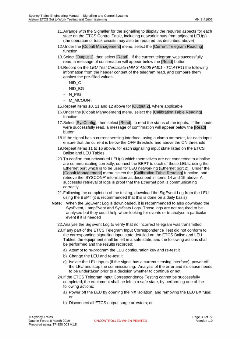
13.7 Activity - LEU Telegram Input Correspondence Testing The LEU Telegram Input Correspondence Test is to prove that all telegrams sent from the LEU to the balise(s) correspond correctly with the associated signalling aspect inputs. Each signalling state described in the ETCS LEU Tables will need to be set and the corresponding telegram transmitted by the LEU should be read by the BEPT using the LEU Ethernet interface. This may require the signaller to set routes and track circuits to be operated by the pulling of fuses or by dropping of track circuits locally.
For each signalling input state detailed on the ETCS Balise and LEU Tables, ensure that the input remained unchanged for at least 30 seconds (in the case of an arrangement which contains LEU networking, this should be increased to 2 minutes).
This testing is undertaken from within the signalling relay room, location case or the ETCS LEU cabinet, and requires the LEU to be connected to the signalling according to the Circuit Book, and powered up:
1. If the signal has a current sensing interface, check the type of lamp that is installed for the signal against those shown in the circuit book. Operate the bypass terminals and the LEU isolation terminals, in accordance with MN S 41604 Alstom ETCS Trackside Maintenance Manual
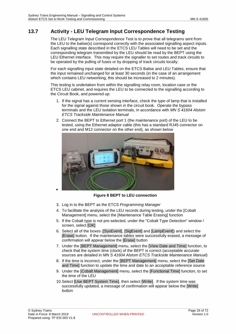
2. Connect the BEPT to Ethernet port 1 (the maintenance port) of the LEU to be tested, using the Ethernet adaptor cable (this has a standard RJ45 connector on one end and M12 connector on the other end), as shown below
• BEPT to LEU connection Figure 8
3. Log in to the BEPT as the ETCS Programming Manager 4. To facilitate the analysis of the LEU records during testing, under the [Cobalt
Management] menu, select the [Maintenance Table Erasing] function 5. If the Cobalt type is not pre-selected, under the “Cobalt Type Detection” window /
screen, select [OK] 6. Select all of the boxes ([SysEvent], [SigEvent] and [LampEvent]) and select the
[Erase] button. If the maintenance tables were successfully erased, a message of confirmation will appear below the [Erase] button
7. Under the [BEPT Management] menu, select the [View Date and Time] function, to check that the system time (clock) of the BEPT is correct (acceptable accurate sources are detailed in MN S 41604 Alstom ETCS Trackside Maintenance Manual)
8. If the time is incorrect, under the [BEPT Management] menu, select the [Set Date and Time] function to update the time and date to an acceptable reference source
9. Under the [Cobalt Management] menu, select the [Functional Time] function, to set the time of the LEU
10. Select [Use BEPT System Time], then select [Write]. If the system time was successfully updated, a message of confirmation will appear below the [Write] button
Sydney Trains Engineering Manual – Signalling and Control Systems Alstom ETCS Set to Work Testing and Commissioning MN S 41605
© Sydney Trains Page 30 of 72 Date in Force: 8 March 2019 UNCONTROLLED WHEN PRINTED Version 1.0 Prepared using: TP ESI 003 V1.8
11. Arrange with the Signaller for the signalling to display the required aspects for each state on the ETCS Control Table, including network inputs from adjacent LEU(s) (the operation of track circuits may also be required, as described above)
12. Under the [Cobalt Management] menu, select the [Current Telegram Reading] function
13. Select [Output 1], then select [Read]. If the current telegram was successfully read, a message of confirmation will appear below the [Read] button
14. Record on the LEU Test Certificate (MN S 41605 FM01 - TC ATP1) the following information from the header content of the telegram read, and compare them against the pre-filled values: – NID_C – NID_BG – N_PIG – M_MCOUNT
15. Repeat items 10, 11 and 12 above for [Output 2], where applicable 16. Under the [Cobalt Management] menu, select the [Calibration Table Reading]
function 17. Select [SysConfig], then select [Read], to read the status of the inputs. If the inputs
were successfully read, a message of confirmation will appear below the [Read] button
18. If the signal has a current sensing interface, using a clamp ammeter, for each input ensure that the current is below the OFF threshold and above the ON threshold
19. Repeat items 11 to 16 above, for each signalling input state listed on the ETCS Balise and LEU Tables
20. To confirm that networked LEU(s) which themselves are not connected to a balise are communicating correctly, connect the BEPT to each of these LEUs, using the Ethernet port which is to be used for LEU networking (Ethernet port 2). Under the [Cobalt Management] menu, select the [Calibration Table Reading] function, and retrieve the ‘SYSCONF’ information as described in items 14 and 15 above. A successful retrieval of logs is proof that the Ethernet port is communicating correctly
21. Following the completion of the testing, download the SigEvent Log from the LEU using the BEPT (it is recommended that this is done on a daily basis)
Note: When the SigEvent Log is downloaded, it is recommended to also download the SysEvent, LampEvent and SysStats Logs. Those logs are not required to be analysed but they could help when looking for events or to analyse a particular event if it is needed
22. Analyse the SigEvent Log to verify that no incorrect telegram was transmitted. 23. If any part of the ETCS Telegram Input Correspondence Test did not conform to
the corresponding signalling input state detailed on the ETCS Balise and LEU Tables, the equipment shall be left in a safe state, and the following actions shall be performed and the results recorded: a) Attempt to re-program the LEU configuration key and re-test it b) Change the LEU and re-test it c) Isolate the LEU inputs (if the signal has a current sensing interface), power off
the LEU and stop the commissioning. Analysis of the error and it’s cause needs to be undertaken prior to a decision whether to continue or not.
24. If the ETCS Telegram Input Correspondence Testing cannot be successfully completed, the equipment shall be left in a safe state, by performing one of the following actions: a) Power off the LEU by opening the NX isolation, and removing the LEU BX fuse;
or b) Disconnect all ETCS output surge arrestors; or
Sydney Trains Engineering Manual – Signalling and Control Systems Alstom ETCS Set to Work Testing and Commissioning MN S 41605
© Sydney Trains Page 31 of 72 Date in Force: 8 March 2019 UNCONTROLLED WHEN PRINTED Version 1.0 Prepared using: TP ESI 003 V1.8
c) For current sensing, bypass the LEU inputs by operating the LEU bypass terminals to the ‘Bypass’ position (i.e. pushed in) and opening the LEU input isolators
Note: For signals with a current sensing interface, prior to any disconnection, the LEU must be switched off and the LEU bypass terminals operated to the ‘Bypass’ position (i.e. pushed in). Closing the LEU bypass terminals alone does not isolate the ETCS equipment.
Note: For signals with a current sensing interface, every time the LEU bypass terminals are operated to the “Not Bypassed’ position (sending the lamp current through the LEU), a complete LEU Telegram Input Correspondence Test must be done to ensure the correct functionality of the terminals.
13.8 Activity - Default Balise Telegram Testing In order to be able to complete the Detailed Balise Telegram Testing, the balise needs to have been programmed with its specific trackside application data.
Caution: This work requires access to the track, so appropriate worksite protection procedures for working in the danger zone must be followed.
The default balise telegram is tested as follows:
1. Identify the balise to be tested, check that the circular balise ID plate conforms to the balise information pre-recorded in the Balise Group Test Certificate (MN S 41605 FM02 - TC ATP2)
2. Ensure that the balise is disconnected from the LEU (this may be done by removing the surge arrestor cassette at the LEU location)
3. Place the BEPT on top of the balise 4. Log in to the BEPT as the ETCS Programming Manager 5. Under the [Balise Management] menu, select the [Telegram Memory Reading]
function 6. A new [Telegram Memory Reading] window / screen will appear. Select the [Read]
button to read the default balise telegram 7. Record on the Balise Group Certificate (MN S 41605 FM02 - TC ATP2) the
following information from the header content of the telegram read, and compare them against the pre-filled values: – NID_C – NID_BG – N_PIG – M_MCOUNT – CRC (Checksum)
Note: The M_MCOUNT value should be 255 for fixed balises or 254 for controlled balises.
8. If any of the CRCs read by the BEPT are different from CRCs written on the relevant ETCS Installed Data Forms (PR S 41015 FM124 - ETCS IDF2), the commissioning of the balise cannot continue until the cause is identified and corrected. This could be due to the following: – Wrong data in the balise. Check that the programming part of the Balise Group
Test Certificate (MN S 41605 FM02 - TC ATP2) has been completed with all of the data according to the ETCS Installed Data Form (PR S 41015 FM124 - ETCS IDF2) and whether or not the CRC was verified & validated. If not, the balise may require re-programming with the correct data
Sydney Trains Engineering Manual – Signalling and Control Systems Alstom ETCS Set to Work Testing and Commissioning MN S 41605
© Sydney Trains Page 32 of 72 Date in Force: 8 March 2019 UNCONTROLLED WHEN PRINTED Version 1.0 Prepared using: TP ESI 003 V1.8
– If the problem continues, the BEPT may be faulty. Try the process again with another BEPT, and quarantine the original BEPT.
9. Repeat items 4 and 5 above, for each balise within the associated balise group 10. If any part of the Default Balise Telegram Test cannot be successfully completed,
the equipment shall be left in a safe state, using one of the following actions, and the results recorded: – Attempt to re-program the balise and re-test it – Replace and re-program the balise, and repeat the activities within section 6.6 – Mute the balise (under the [Balise Management (AF)] menu, select the
[Operating Mode] function; under [Mode], select [Silent], then select [Set]) – Remove the balise from the track if no other previous option is possible
Note: If it is a controlled balise, the surge arrestor must be disconnected first.
13.9 Activity - ETCS Functional Testing The purpose of the test is to verify the complete communication from the signalling system to a controlled balise and hence prove that both the Signalling to LEU interface and the LEU to balise interface are working.
ETCS Functional Testing is performed as follows:
1. Identify the controlled balise to be tested, check that the LEU ID plate, the LEU output number and the circular balise ID plate conform to the balise information pre-recorded in the Balise Group Test Certificate (MN S 41605 FM02 - TC ATP2)
2. Place the BEPT on top of the balise 3. Log in to the BEPT as the ETCS Programming Manager 4. Arrange with the Signaller for the signalling to display a valid proceed aspect 5. Under the [Balise Management] menu, select the [Telegram Memory Reading]
function 6. A new [Telegram Memory Reading] window / screen will appear. Select the [Read]
button to read the default balise telegram 7. Record on the LEU Test Certificate (MN S 41605 FM01 - TC ATP1) the following
information from the header content of the telegram read, and compare them against the pre-filled values: – NID_C – NID_BG – N_PIG – M_MCOUNT (subject to signal indication, cannot be ‘254’)
8. Ensure that the LEU is sending information to the correct balise. This can be accomplished in two different ways: a) Using the BEPT on the balise, and breaking the circuit between the LEU and
balise, o Under the [Balise Management] menu, select the [Telegram Reading]
function, and check that the values correspond to the signal aspect o Break the connection from the LEU to the balise at any point (e.g. by
removing the surge arrestor at the LEU), and check that the above values correspond to the default telegram
Note: Make sure that the [Telegram Memory Reading] function is NOT used to perform this test.
o Re-connect the LEU to the balise and check the values again o All readings must have the same values for NID_C, NID_BG, and N_PIG.
The only value which should change is the M_MCOUNT. b) Using only the BEPT on the balise,
Sydney Trains Engineering Manual – Signalling and Control Systems Alstom ETCS Set to Work Testing and Commissioning MN S 41605
© Sydney Trains Page 33 of 72 Date in Force: 8 March 2019 UNCONTROLLED WHEN PRINTED Version 1.0 Prepared using: TP ESI 003 V1.8
o Read the default ETCS telegram by using the [Telegram Memory Reading] function under the [Balise Management] menu
o Read the current ETCS telegram by using the [Telegram Reading] function under the [Balise Management] menu (which must correspond to the current signalling aspect)
o Both readings must have the same values for NID_C, NID_BG and N_PIG, and different values for the M_MCOUNT.
9. If any part of the ETCS Functional Testing cannot be successfully completed, the equipment shall be left in a safe state and at least one of the following actions shall be performed and the results recorded: – If possible, resolve the problem, and re-test – Power OFF the LEU and mute the balise (under the [Balise Management (AF)]
menu, select the [Operating Mode] function; under [Mode], select [Silent], then select [Set])
– Remove the balise from the track if no other previous option is possible. Note: If it is a controlled balise, the surge arrestor at the LEU must be disconnected
first.
10. If the equipment is not to be put into service immediately after the tests, the equipment shall be left in a safe state by performing the following actions: – Ensure that the LEU is powered off by removing the fuse – Ensure that the corresponding balise(s) are muted (under the [Balise
Management (AF)] menu, select the [Operating Mode] function; under [Mode], select [Silent], then select [Set]).

Sydney Trains Engineering Manual – Signalling and Control Systems Alstom ETCS Set to Work Testing and Commissioning MN S 41605
© Sydney Trains Page 34 of 72 Date in Force: 8 March 2019 UNCONTROLLED WHEN PRINTED Version 1.0 Prepared using: TP ESI 003 V1.8
14 Final Adjustment and Commissioning
14.1 Activity - Communicating Results As soon as possible, after the testing of each ETCS equipped location is completed, the Tester in Charge is to advise the Commissioning Engineer so that the log can be updated.
If any problem is found with the ETCS trackside system, notify the Commissioning Engineer as soon as possible. If the problem precludes immediate completion of testing and there are other locations to be commissioned, then it may be necessary to proceed to the next ETCS equipped location to be commissioned and return when necessary corrections have been carried out.
14.2 Activity - Final Documentation The Commissioning Engineer shall ensure that:
• the ETCS trackside testing records are completed and signed for all ETCS trackside equipment tested by the team.
• all defects or problems encountered are recorded in the commissioning log. • all ETCS trackside equipment commissioned, and all ETCS trackside equipment
allocated to, but not completed by the team for whatever reason, are recorded either in the test records or the commissioning log.
Sydney Trains Engineering Manual – Signalling and Control Systems Alstom ETCS Set to Work Testing and Commissioning MN S 41605
© Sydney Trains Page 35 of 72 Date in Force: 8 March 2019 UNCONTROLLED WHEN PRINTED Version 1.0 Prepared using: TP ESI 003 V1.8
Appendix A Applicable ETCS Forms and Test Certificates The forms and test certificates shown on the following pages are samples only.
TfNSW may have developed later versions of these which are not yet included in this document.
Only the most current version of the forms and test certificates listed below are to be used. These are available from the Sydney Trains intranet and internet pages.
An AEO shall not make alterations to these forms and test certificates without the prior approval from the Professional Head Signalling & Control Systems Sydney Trains.
• MN S 41605 FM01 LEU Test Certificate - TC ATP1 (previously TCXX) • MN S 41605 FM02 Balise Group Test Certificate - TC ATP2 (previously TCYY) • MN S 41605 FM03 Installed LEU Equipment Information Certificate - TC ATP3
(previously TCZZ) • MN S 41605 FM04 Location Power Supply Test Certificate - TC ATP4 (previously
TC7a Mod) • MN S 41605 FM05 LEU Cabinet Inspection and Testing Checklist - ITF ATP1
(previously ITF13/XX) • MN S 41605 FM06 Balise Group Inspection and Testing Checklist - ITF ATP2
(previously ITF13/YY) The format and structure of the following forms shall not be changed:
• PR S 41015 FM125 (ETCS) Installed Data Form - LEU Configuration Key - ETCS IDF1 (located in CB)
• PR S 41015 FM124 (ETCS) Installed Data Form & Balise Register - ETCS IDF2 (located in CB)
• PR S 41015 FM123 (ETCS) Site Certification Form (SCF located in CB) Notes:
• The information on the following sample forms, shown in red is example information only.
• Ensure that the "Asset Name" and the "Distance" details recorded on the ETCS Installed Data Form & Balise Position Register matches the as-measured balise positions, as recorded on the SCF (PR S 41015 FM123). Whilst two lines are shown on the form, in most cases only one infrastructure asset will be used as a measurement reference.
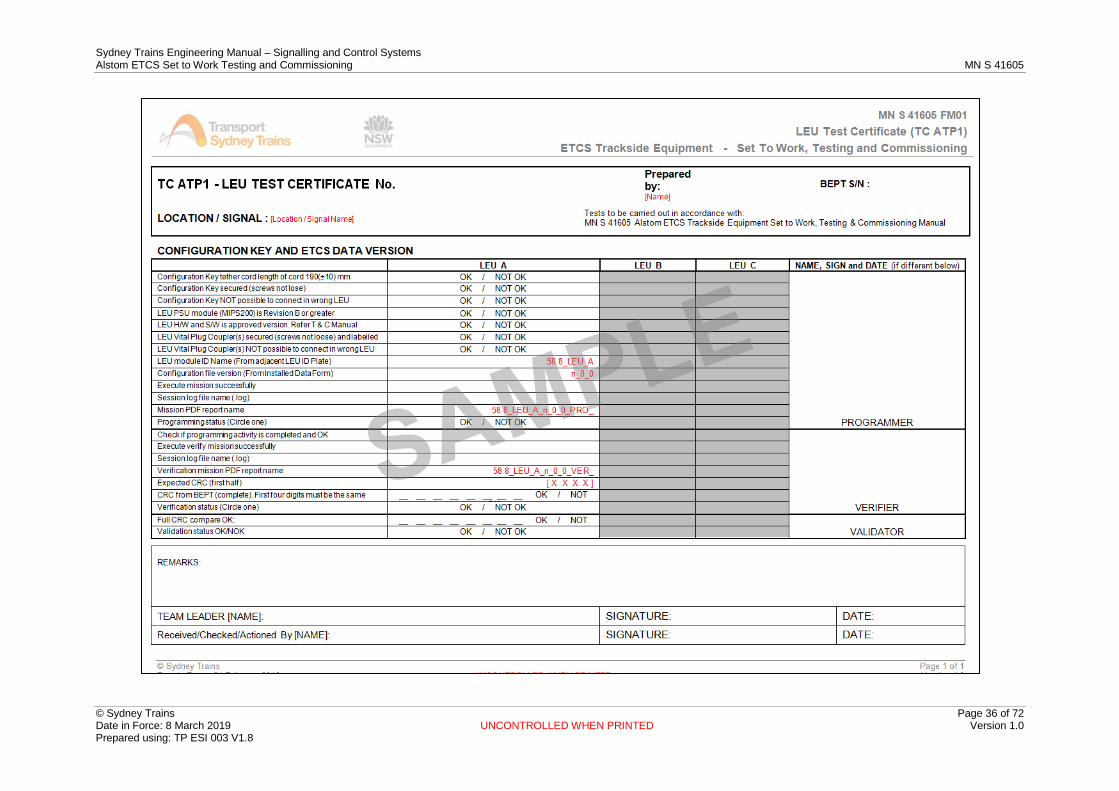
Sydney Trains Engineering Manual – Signalling and Control Systems Alstom ETCS Set to Work Testing and Commissioning MN S 41605
© Sydney Trains Page 36 of 72 Date in Force: 8 March 2019 UNCONTROLLED WHEN PRINTED Version 1.0 Prepared using: TP ESI 003 V1.8

Sydney Trains Engineering Manual – Signalling and Control Systems Alstom ETCS Set to Work Testing and Commissioning MN S 41605
© Sydney Trains Page 37 of 72 Date in Force: 8 March 2019 UNCONTROLLED WHEN PRINTED Version 1.0 Prepared using: TP ESI 003 V1.8
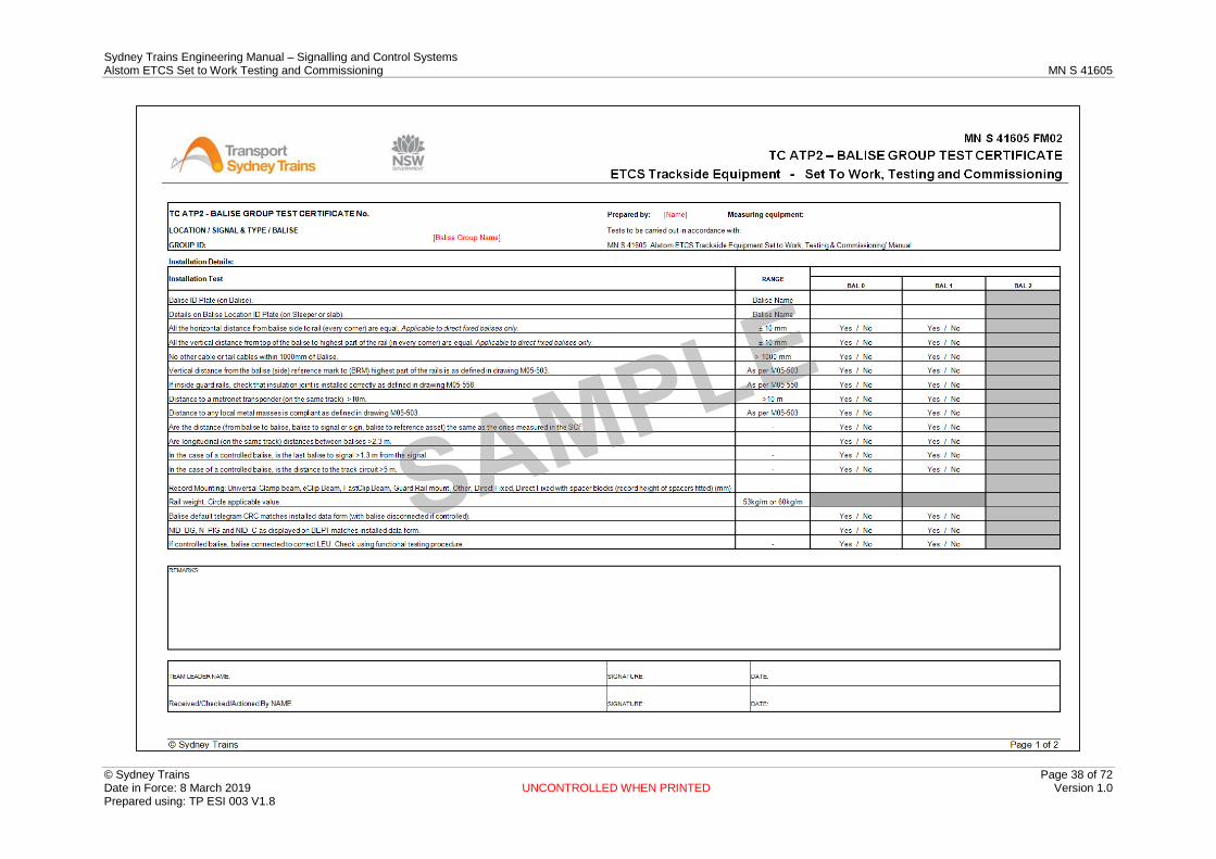
Sydney Trains Engineering Manual – Signalling and Control Systems Alstom ETCS Set to Work Testing and Commissioning MN S 41605
© Sydney Trains Page 38 of 72 Date in Force: 8 March 2019 UNCONTROLLED WHEN PRINTED Version 1.0 Prepared using: TP ESI 003 V1.8

Sydney Trains Engineering Manual – Signalling and Control Systems Alstom ETCS Set to Work Testing and Commissioning MN S 41605
© Sydney Trains Page 39 of 72 Date in Force: 8 March 2019 UNCONTROLLED WHEN PRINTED Version 1.0 Prepared using: TP ESI 003 V1.8

Sydney Trains Engineering Manual – Signalling and Control Systems Alstom ETCS Set to Work Testing and Commissioning MN S 41605
© Sydney Trains Page 40 of 72 Date in Force: 8 March 2019 UNCONTROLLED WHEN PRINTED Version 1.0 Prepared using: TP ESI 003 V1.8

Sydney Trains Engineering Manual – Signalling and Control Systems Alstom ETCS Set to Work Testing and Commissioning MN S 41605
© Sydney Trains Page 41 of 72 Date in Force: 8 March 2019 UNCONTROLLED WHEN PRINTED Version 1.0 Prepared using: TP ESI 003 V1.8
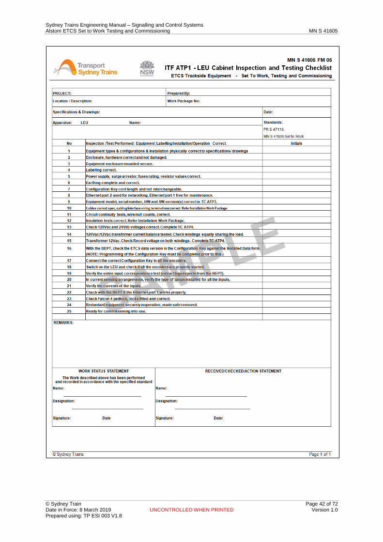
Sydney Trains Engineering Manual – Signalling and Control Systems Alstom ETCS Set to Work Testing and Commissioning MN S 41605
© Sydney Train Page 42 of 72 Date in Force: 8 March 2019 UNCONTROLLED WHEN PRINTED Version 1.0 Prepared using: TP ESI 003 V1.8
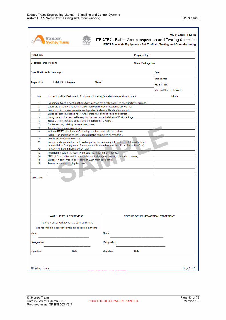
Sydney Trains Engineering Manual – Signalling and Control Systems Alstom ETCS Set to Work Testing and Commissioning MN S 41605
© Sydney Trains Page 43 of 72 Date in Force: 8 March 2019 UNCONTROLLED WHEN PRINTED Version 1.0 Prepared using: TP ESI 003 V1.8

Sydney Trains Engineering Manual – Signalling and Control Systems Alstom ETCS Set to Work Testing and Commissioning MN S 41605
© Sydney Train Page 44 of 72 Date in Force: 8 March 2019 UNCONTROLLED WHEN PRINTED Version 1.0 Prepared using: TP ESI 003 V1.8

Sydney Trains Engineering Manual – Signalling and Control Systems Alstom ETCS Set to Work Testing and Commissioning MN S 41605
© Sydney Trains Page 45 of 72 Date in Force: 8 March 2019 UNCONTROLLED WHEN PRINTED Version 1.0 Prepared using: TP ESI 003 V1.8
Sydney Trains Engineering Manual – Signalling and Control Systems Alstom ETCS Set to Work Testing and Commissioning MN S 41605
© Sydney Train Page 46 of 72 Date in Force: 8 March 2019 UNCONTROLLED WHEN PRINTED Version 1.0 Prepared using: TP ESI 003 V1.8
Appendix B Part Number Management Each mission executed by the BEPT needs to be associated with an item of equipment (e.g. balise or LEU configuration key), which are defined by a part number (e.g. balise type DTR0000273037 or LEU type DTR2000003567).
In order for mission importing or mission creation to work, approved part numbers for each item of equipment need to be defined first within the BEPT. These part numbers should come pre-defined within the BEPT when it is delivered, however if the BEPT requires a system reset for whatever reason, the part numbers will be erased. A list of the required part numbers for balises and LEUs will be included in the ETCS Data Design package issued by the Data Design team to the ETCS Programmer, along with the missions and the LEU and balise data.
Data Design team to check that the BEPT Contains Current Part Numbers:
1. Log in to the BEPT as the ETCS Programming Manager
2. Under the [Mission Management] menu, select the [Part Number Management] function
3. Under [Choose Equipment], select either [Balise] or [Cobalt], and check that all of the required LEU and balise part numbers are present. If no part numbers are defined within the BEPT, follow the process below to create new part numbers.
To Create New Part Numbers:
1. Log in to the BEPT as the ETCS Programming Manager
2. Under the [Mission Management] menu, select the [Part Number Management] function
3. Under [Choose Equipment], select either [Balise] or [Cobalt], depending upon whether the mission to be created is for a balise or an LEU, and select the [New] button
4. In the [Part Number Management] screen / window, select [Balise] or [Cobalt], enter the [Part Number] and [Description] and select the [Save] button to add the new part number. Once the new Part Number has been saved, a message of confirmation will appear below the [Save] button.
Alstom Equipment Part Numbers This document is applicable to the products and versions of Alstom ETCS trackside equipment listed below only.
Note: The Programming Preparation Tool (PPT) is the software tool used by the Data Design team to check part numbers.
LEU The following versions are approved for use (refer notes1 and 2):
• P/N DTR2000003567 version B • P/N DTR0000245619 with version U hardware and SW V431 • P/N DTR0000245619 with version T hardware and SW V431 • P/N DTR0000245619 with version S hardware and SW V431
Note 1: Latest Alstom part number DTR2000003567 incorporates both hardware and software. A separate hardware label DTR0000245619 and software label eg.: V431 may also be included. If either the hardware or the software changes, the version letter will change.
Note 2: Part number DTR0000245619 is hardware only with software identified separately.
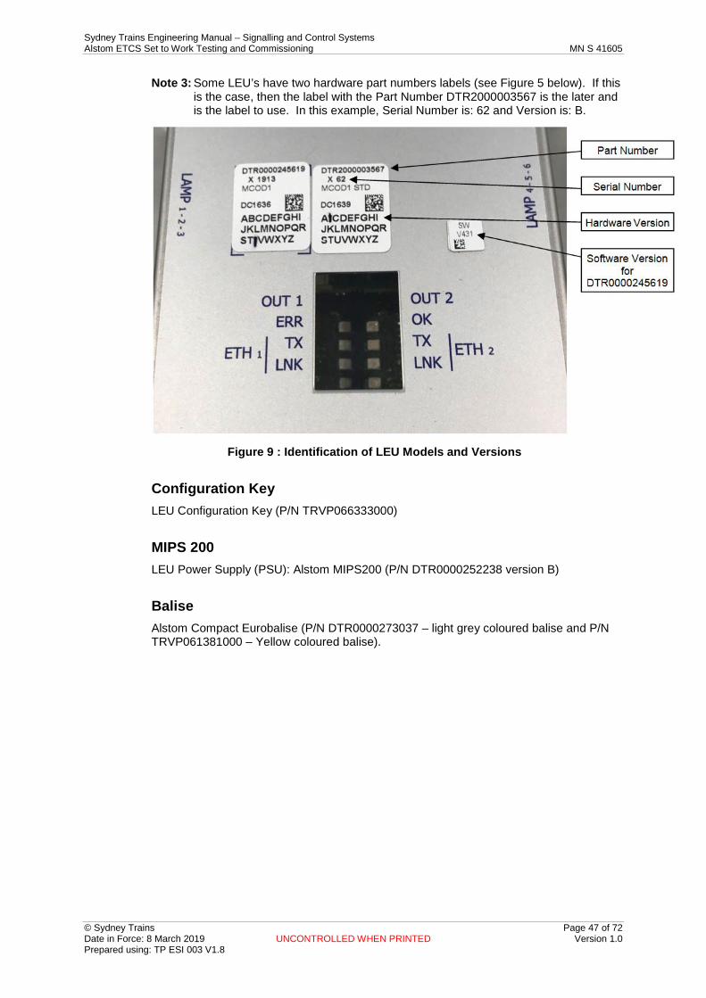
Sydney Trains Engineering Manual – Signalling and Control Systems Alstom ETCS Set to Work Testing and Commissioning MN S 41605
© Sydney Trains Page 47 of 72 Date in Force: 8 March 2019 UNCONTROLLED WHEN PRINTED Version 1.0 Prepared using: TP ESI 003 V1.8
Note 3: Some LEU’s have two hardware part numbers labels (see Figure 5 below). If this is the case, then the label with the Part Number DTR2000003567 is the later and is the label to use. In this example, Serial Number is: 62 and Version is: B.
: Identification of LEU Models and Versions Figure 9
Configuration Key LEU Configuration Key (P/N TRVP066333000)
MIPS 200 LEU Power Supply (PSU): Alstom MIPS200 (P/N DTR0000252238 version B)
Balise Alstom Compact Eurobalise (P/N DTR0000273037 – light grey coloured balise and P/N TRVP061381000 – Yellow coloured balise).
Sydney Trains Engineering Manual – Signalling and Control Systems Alstom ETCS Set to Work Testing and Commissioning MN S 41605
© Sydney Trains Page 48 of 72 Date in Force: 8 March 2019 UNCONTROLLED WHEN PRINTED Version 1.0 Prepared using: TP ESI 003 V1.8
Appendix C Mission Creation and Data Importing The term 'mission' refers to a data file containing a consolidated set of pre-defined programming or verification activities, prepared either by the ETCS Programmer or by the Data Design team, and loaded on to the BEPT. A mission is executed by the respective ETCS Programmer or ETCS Verifier, and prevents errors in the installation and testing by limiting these activities to those which are pre-defined, and associated with the correct balise or LEU.
The creation of missions is a pre-requisite for ETCS data installation (Alstom call this “programming”) and ETCS data testing (Alstom call this “verification”) activities and should be performed prior to attending site.
Missions can be created directly into the BEPT or created with an XML editor (not covered by this document) and imported into the BEPT (see Section 17.1).
Mission creation by the Data Design team either requires the BEPT to be taken to the Data Design office for programming, or for the missions to be issued to the ETCS Installation team for importing into the BEPT along with the issued balise and LEU data.
One data installation (programming) mission and one data installation (verification) mission is required for each LEU or balise. Associated Inspection and Testing Checklists and Test Certificates for the on-site activities are also required.
The Programming Preparation Tool (PPT) is the software tool used by the Data Design team on an approved PC to create the Verification Report and Validation Report, and is also used to convert the balise files into the format for programming (mission creation).
If the installation team are required to import missions (prepared in advance) and .xml files into the BEPT, the process described in the section 17.2 shall be followed.
If the installation team are required to create missions in the BEPT, the process described in the Section 17.1 shall be followed.
Mission Creation by Installation Team
Items Required for Mission Creation An ETCS Data Release Note provided by the Data Design team (as per QSDP29_F56).
The corresponding LEU and balise data files:
• Balise configuration data (OGM, UDF files, and associated SHA files); or • LEU configuration data (BIN, GID and PRM files plus the associated SHA files)
An ETCS Installed Data Form PR S 41015 FM124/125 (ETCS IDF2/1). This is included in the approved Circuit Book design provided by the Data Design team.
The BEPT which will be used for the ETCS data installation and ETCS data testing (where the missions will be created or imported).
WARNING: At the time of ETCS data installation and testing, the ETCS Installed Data
Form (ETCS IDF1/2) should include a BLANK checksum, as the generation of the CRC’s during the testing process is a key part of the data validation
process.

Sydney Trains Engineering Manual – Signalling and Control Systems Alstom ETCS Set to Work Testing and Commissioning MN S 41605
© Sydney Trains Page 49 of 72 Date in Force: 8 March 2019 UNCONTROLLED WHEN PRINTED Version 1.0 Prepared using: TP ESI 003 V1.8
BEPT Preparation: 1. Connect the BEPT to an appropriately configured laptop PC or Alstom Algiz7
Tablet (the Alstom PDA cannot be used for mission creation, as not all functions are accessible through the PDA interface).
2. Log into the BEPT as the ETCS Programming Manager
3. The following menu should be displayed:
Note: This is an example screen and the actual menu could appear differently on different devices.
: BEPT Programming Manager Menu Figure 10
Importing Balise and LEU data files into the BEPT 1. Connect the USB memory stick containing the required balise and LEU files to the
USB port on the BEPT.
2. Under the [BEPT Management] menu, select the [Import Data] function.
3. Under [Choose Equipment] Select either [Balise] or [Cobalt], depending upon whether the mission to be created is for an LEU or a balise.
4. Specify the directory in which the configurations files are located on the USB memory stick.
5. Select the individual files to import, or use [Select All], and select the [Import] button.
6. An error message will be shown by the BEPT if all of the files needed to program a single balise (OGM and UDF files) or LEU (BIN, GID and PRM files) are not located within the same directory, or if for some reason not all of the files could be imported. If the importing of data was successful, a message of confirmation will appear below the [Import] button.
Sydney Trains Engineering Manual – Signalling and Control Systems Alstom ETCS Set to Work Testing and Commissioning MN S 41605
© Sydney Trains Page 50 of 72 Date in Force: 8 March 2019 UNCONTROLLED WHEN PRINTED Version 1.0 Prepared using: TP ESI 003 V1.8
BEPT Mission Creation Within the BEPT 1. Under the [Mission Management] menu, select the [Manage Mission] function, and
select [Create].
2. Under [Equipment] select either [Balise] or [Cobalt], depending upon whether the mission to be created is for an LEU or a balise.
3. Under [Template] select either [ProgBalise], [VerBalise], [ProgCobaltKey] or [VerCobaltKey], depending upon whether the mission to be created is for data installation (programming) or data testing (verification).
4. Under [User ID] either [install] or [verify] should be automatically filled, depending upon the choice of template.
5. Under [Date Expiry] enter the required date for the mission to expire (for flexibility, the date selected should be after the latest possible date for the commissioning of the area or project).
6. Under [Reference File Rep: Import Data] select the name of the balise or LEU to be associated with this mission.
7. Under [Mission Name] the name of the mission to be created will be automatically filled, using the name of the balise or LEU selected above, with “Pro” or “Ver” appended to the name, depending on whether the mission was for data installation (programming) or data testing (verification).
8. Under [Report Name] enter the name of the mission report to be created, by copying and pasting the [Mission Name] created above.
9. Select the [Save] button to generate the mission. If the mission creation was successful, a message of confirmation will appear below the [Save] button.
Additional considerations The CRC values inside one BEPT must be unique. The management of CRCs is the responsibility of the Data Design team, and if any errors are found due to duplicated CRCs, the Data Design team must be consulted and a resolution sought.
Mission Creation by Data Design Team This section details the activities necessary to configure the BEPT when missions are prepared in advance / remotely (normally by the Data Design team), and are issued to the ETCS Programmer, along with the LEU and balise data.
These activities may be undertaken by the ETCS Programmer or ETCS Verifier, but not the ETCS data Validator who is required to remain independent.
Items required for importing a mission into the BEPT:
• Approved USB memory stick with the pre-prepared missions • BEPT and PC
WARNING: At the time of ETCS data installation and testing, the ETCS Installed Data
Form (ETCS IDF1/2) should include a BLANK checksum, as the generation of the CRC’s during the testing process is a key part of the data validation
process.
Sydney Trains Engineering Manual – Signalling and Control Systems Alstom ETCS Set to Work Testing and Commissioning MN S 41605
© Sydney Trains Page 51 of 72 Date in Force: 8 March 2019 UNCONTROLLED WHEN PRINTED Version 1.0 Prepared using: TP ESI 003 V1.8
Importing a Mission into the BEPT 1. Log in to the BEPT as the Programming Manager [“ertms”].
2. Erase all existing missions and data from the BEPT. To do this, under the [Mission Management] menu, select the [Manage Mission] function, select the missions to be deleted (or use [Select All]) and select [Delete]. If the mission erasing was successful, a message of confirmation will appear below the [Delete] button.
Note: This process will also delete all associated LEU / Balise data files.
3. Connect the USB memory stick containing the required mission files to the USB port on the BEPT.
4. Under the [Mission Management] menu, select the [Import Mission] function.
5. Use the [Browse] function to select the USB memory stick folder containing the mission files and LEU / balise data files to be imported, and select the [OK] button.
6. Select the missions to be imported (or select [All Files]) and select [Import]. The missions and corresponding LEU / balise data files will be save into the BEPT. If the mission importing was successful, a message of confirmation will appear below the [Import] button.
Note: each XML file should contain on programming (.Pro) mission and one verification (.Ver) mission for each installation.
7. Log out of the Programming Manager profile.

Sydney Trains Engineering Manual – Signalling and Control Systems Alstom ETCS Set to Work Testing and Commissioning MN S 41605
© Sydney Trains Page 52 of 72 Date in Force: 8 March 2019 UNCONTROLLED WHEN PRINTED Version 1.0 Prepared using: TP ESI 003 V1.8
Appendix D Programming an LEU Configuration Key For a project involving new fitments of ETCS, it is most likely that the data installation (programming) and data testing (verification) of an LEU configuration key is undertaken prior to taking the equipment to trackside. The LEU Configuration Key Functional Tests detailed in sections 13.5, 13.7, 13.8 and 13.9 of this document are undertaken on site once the LEU configuration key is installed in the location case, relay room or ATP cabinet, to ensure that a pre-programmed LEU configuration key is installed at the correct LEU.
Important: For LEU configuration key data programming, testing and validation, it is importance that independence is maintained between the Data Design Team, ETCS Programmer, ETCS Verifier, and ETCS data Validator.
The trackside configuration data for an LEU is programmed into an LEU configuration key, which is connected to the corresponding LEU. This avoids the need to re-programme the LEU data in the case of a failed LEU. The configuration data for an LEU is loaded on start-up, as long as the LEU configuration key is attached.
Items required for LEU Configuration Key programming:
• LEU configuration key adaptor. • BEPT and PC or Algiz7 terminal. • Forms: LEU Test Certificate TC ATP1 (MN S 41605 FM01) and ETCS Installed
Data Form - LEU Configuration Key – ETCS IDF1 (PR S 41015 FM125). Prior to commencing the programming process, check the following:
• Before being used for a configuration key programming session, the BEPT shall be shut down, at least once, to clean the data stored into the volatile memory from the previous programming sessions.
• All of the required LEU data files have been imported into the BEPT. • The installation (programming) and testing (verification) missions for each LEU to
be programmed have already been programmed into the BEPT. • The specific Test Certificates have been created, prefilled (where required), and
are available. • The Commissioning Work Instruction and the Inspection and Test Checklist are
available. Note: If the LEU configuration key needs to be programmed (or the LEU configuration
key data needs to be updated), the BEPT is used. When programming an LEU configuration key, the key must be plugged into the BEPT via an LEU configuration key cable adaptor.
Programming the LEU Configuration Key 1. Determine the LEU configuration key data configuration file from the ETCS
Installed Data Form - PR S 41015 FM125 LEU Configuration Key (ETCS IDF1).
2. Ensure that the required missions and LEU configuration data are available in the BEPT to be used for data installation.
3. If the programming is done at trackside, check the identity of the LEU (LEU ID plate) to ensure that it is the correct LEU to be programmed. If the programming is done offsite, ensure that the LEU configuration key has a suitable temporary label to identify it at the time of trackside installation. Label shall include details of: LEU name, date of programming, programmers name and configuration file version.
4. Connect the LEU configuration key to be programmed to the BEPT via the LEU configuration key adaptor as shown in the diagram below.
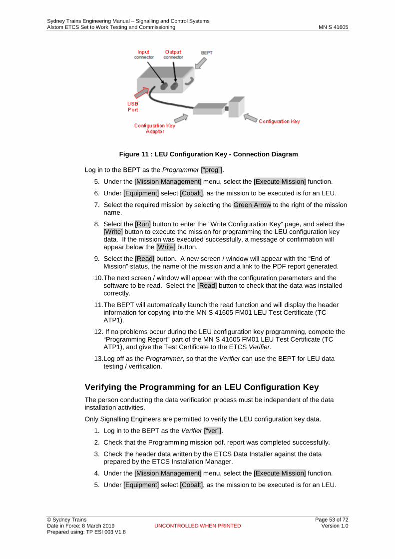
Sydney Trains Engineering Manual – Signalling and Control Systems Alstom ETCS Set to Work Testing and Commissioning MN S 41605
© Sydney Trains Page 53 of 72 Date in Force: 8 March 2019 UNCONTROLLED WHEN PRINTED Version 1.0 Prepared using: TP ESI 003 V1.8
: LEU Configuration Key - Connection Diagram Figure 11
Log in to the BEPT as the Programmer [“prog”].
5. Under the [Mission Management] menu, select the [Execute Mission] function.
6. Under [Equipment] select [Cobalt], as the mission to be executed is for an LEU.
7. Select the required mission by selecting the Green Arrow to the right of the mission name.
8. Select the [Run] button to enter the “Write Configuration Key” page, and select the [Write] button to execute the mission for programming the LEU configuration key data. If the mission was executed successfully, a message of confirmation will appear below the [Write] button.
9. Select the [Read] button. A new screen / window will appear with the “End of Mission” status, the name of the mission and a link to the PDF report generated.
10. The next screen / window will appear with the configuration parameters and the software to be read. Select the [Read] button to check that the data was installed correctly.
11. The BEPT will automatically launch the read function and will display the header information for copying into the MN S 41605 FM01 LEU Test Certificate (TC ATP1).
12. If no problems occur during the LEU configuration key programming, compete the “Programming Report” part of the MN S 41605 FM01 LEU Test Certificate (TC ATP1), and give the Test Certificate to the ETCS Verifier.
13. Log off as the Programmer, so that the Verifier can use the BEPT for LEU data testing / verification.
Verifying the Programming for an LEU Configuration Key The person conducting the data verification process must be independent of the data installation activities.
Only Signalling Engineers are permitted to verify the LEU configuration key data.
1. Log in to the BEPT as the Verifier [“ver”].
2. Check that the Programming mission pdf. report was completed successfully.
3. Check the header data written by the ETCS Data Installer against the data prepared by the ETCS Installation Manager.
4. Under the [Mission Management] menu, select the [Execute Mission] function.
5. Under [Equipment] select [Cobalt], as the mission to be executed is for an LEU.

Sydney Trains Engineering Manual – Signalling and Control Systems Alstom ETCS Set to Work Testing and Commissioning MN S 41605
© Sydney Trains Page 54 of 72 Date in Force: 8 March 2019 UNCONTROLLED WHEN PRINTED Version 1.0 Prepared using: TP ESI 003 V1.8
6. Select the required mission by selecting the Green Arrow to the right of the mission name.
7. Select the [Run] button to enter the “Read Configuration Key” page, and select the [Read] button to execute the mission for verifying the LEU configuration key data. If the mission was executed successfully, a message of confirmation will appear below the [Read] button, and the BEPT will display the CRC, as shown below;
: Data Verification Confirmation message Figure 12
8. Enter the full CRC onto the MN S 41605 FM01 LEU Test Certificate (TC ATP1) and the PR S 41015 FM125 ETCS Installed Data Form (ETCS IDF1).
9. Select the [Next] button. A new screen / window will appear with the “End of Mission” status, the name of the mission and a link to the PDF report generated.
10. If no problems occur during the LEU configuration key verification, complete the MN S 41605 FM01 LEU Test Certificate (TC ATP1) with “OK”. If a “Not OK” result is encountered report to the Commissioning Engineer for further investigation and direction.
11. Record the session log file name and verification report name..
12. Once the LEU configuration key data has been installed and verified using the BEPT, it is essential that all trackside configuration data and missions are deleted from the BEPT, the Handheld ALGIZ7 Tablet and the USB Memory Stick, to prevent incorrect data being used for future tasks.
13. Make available the signed and completed MN S 41605 FM01 LEU Test Certificate (TC ATP1) and the PR S 41015 FM125 ETCS Installed Data Form (ETCS IDF1) to the ETCS data Validator (see Appendix H (LEU and Balise Validation Activities)).
Note 1: The certification of the LEU configuration key is not considered complete until the validation activities are undertaken and the form has been signed by the Validator.
Note 2: If the programming and verification was undertaken on-site:
1. Connect the LEU configuration key to the equipment frame of the signalling location case or relay room, adjacent to the associated LEU, using the tether cord.
2. Re-start the LEU to pair it with the LEU configuration key and to load the site configuration data.
Note 3: If the LEU was previously paired with another LEU configuration key, the LEU will go into BOOT_FAILED mode, with the red ERROR LED flashing. In this case, a Gold Key (a special LEU configuration key with specific data to remove the permanent pairing between the LEU and the LEU configuration key data) must be used before the newly programmed LEU configuration key can be used.
Note 4: As the data should be the same, no error should occur.
Note 5: In the event of problems occurring with verification, the Commissioning Engineer shall liaise with the ATP Design Manager

Sydney Trains Engineering Manual – Signalling and Control Systems Alstom ETCS Set to Work Testing and Commissioning MN S 41605
© Sydney Trains Page 55 of 72 Date in Force: 8 March 2019 UNCONTROLLED WHEN PRINTED Version 1.0 Prepared using: TP ESI 003 V1.8
Downloading of Programming and Verification Reports Once all LEU configuration key data installation (programming) and testing (verification) activities have been completed, all reports (including session logs, mission (pdf.) reports and activity reports) must be downloaded and stored as a record of the activities completed, and for use by the Validator. As these reports expire after time, and the BEPT is limited to the amount of data it can store before overwriting the data, the downloading must be undertaken regularly (daily is suggested).
1. Log in to the BEPT as the ETCS Verifier.
2. Under the [BEPT Management] menu, select the [Export Data] function.
3. Select [Reports] and then select [Cobalt].
4. A list of all of the reports created will appear (the file name is the mission name plus the date and hour when the LEU was programmed). Select the reports to be downloaded (or use [Select All]), under [Directory] select [Browse] to specify location of the USB memory stick and the desired file location, and select [Export]. If the mission report exporting was completed successfully, a message of confirmation will appear below the [Export] button.
5. To save the activity reports for all activities undertaken on any given day, under the [BEPT Management] menu, select the [Activity Report] function.
Select the [User] (either “install” or “verify”) and the [Date], then select the [Generate] button. The BEPT will generate a report file for the activity report with a name containing the User ID plus the date, and an option to open or save the report will appear.
Sydney Trains Engineering Manual – Signalling and Control Systems Alstom ETCS Set to Work Testing and Commissioning MN S 41605
© Sydney Trains Page 56 of 72 Date in Force: 8 March 2019 UNCONTROLLED WHEN PRINTED Version 1.0 Prepared using: TP ESI 003 V1.8
Appendix E Programming a Balise For a project involving new fitments of AMS, it is most likely that the data installation (programming) and data testing (verification) of a balise is undertaken prior to taking the equipment to trackside. The Balise Functional Tests detailed in sections 14.7, 14.8 and 14.9 of this document are undertaken on site once the balise is installed on track, to ensure that a pre-programmed balise is installed at the correct location.
Important: For balise data programming, testing and validation, it is importance that independence is maintained between the Data Design Team, ETCS Programmer, ETCS Verifier, and ETCS data Validator.
Each balise has a default telegram stored in its internal memory. This is the only telegram sent by a fixed balise, and is the telegram sent by a controlled balise when the LEU / balise interface is faulty.
Items required for Balise programming:
• BEPT and PC or Algiz7 terminal. • Form: MN S 41605 FM02 Balise Group Test Certificate TC ATP2 and
PR S 41015 FM124 ETCS Installed Data Form - Balise (ETCS IDF1). Prior to commencing the programming process, check the following:
• Before being used for a balise programming session, the BEPT shall be shut down, at least once, to clean the data stored into the volatile memory from the previous programming sessions.
• All of the required balise data files have been imported into the BEPT. • The installation (programming) and testing (verification) missions for each balise to
be programmed have already been programmed into the BEPT. • The specific Test Certificates have been created, prefilled (where required), and
are available. • The Commissioning Work Instruction and the Inspection and Test Checklist are
available.
Programming the Balise 1. Determine the balise data configuration file from the PR S 41015 FM124 ETCS
Installed Data Form - Balise (ETCS IDF1).
2. Ensure that the required missions and balise configuration data are available in the BEPT to be used for data installation.
3. If the programming is done at trackside, check the identity of the balise (using the circular balise ID plate affixed to the balise and rectangular balise location ID plate affixed to the sleeper) to ensure that it is the correct balise to be programmed. If the balise programming was done off site or prior to installation:
– ensure that the balise has its balise ID plate affixed to identify it at the time of trackside installation
– read the balise telegram (NID_C, NID_BG and N_PIG) and check the balise identity matches the balise ID and balise ID plate identifications
4. Copy the serial number from the balise label onto the specific Balise Group Test Certificate (TC ATP2) or check that it is correct (if the Test Certificate has already been completed).
5. Place the BEPT on top of the balise (programming is carried out via the air gap interface).
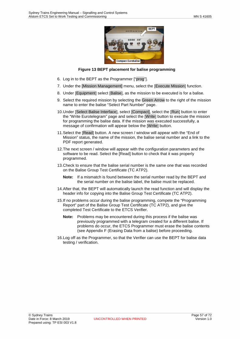
Sydney Trains Engineering Manual – Signalling and Control Systems Alstom ETCS Set to Work Testing and Commissioning MN S 41605
© Sydney Trains Page 57 of 72 Date in Force: 8 March 2019 UNCONTROLLED WHEN PRINTED Version 1.0 Prepared using: TP ESI 003 V1.8
BEPT placement for balise programming Figure 13
6. Log in to the BEPT as the Programmer [“prog”].
7. Under the [Mission Management] menu, select the [Execute Mission] function.
8. Under [Equipment] select [Balise], as the mission to be executed is for a balise.
9. Select the required mission by selecting the Green Arrow to the right of the mission name to enter the balise “Select Part Number” page.
10. Under [Select Balise Interface], select [Compact], select the [Run] button to enter the “Write Eurotelegram” page and select the [Write] button to execute the mission for programming the balise data. If the mission was executed successfully, a message of confirmation will appear below the [Write] button.
11. Select the [Read] button. A new screen / window will appear with the “End of Mission” status, the name of the mission, the balise serial number and a link to the PDF report generated.
12. The next screen / window will appear with the configuration parameters and the software to be read. Select the [Read] button to check that it was properly programmed.
13. Check to ensure that the balise serial number is the same one that was recorded on the Balise Group Test Certificate (TC ATP2).
Note: If a mismatch is found between the serial number read by the BEPT and the serial number on the balise label, the balise must be replaced.
14. After that, the BEPT will automatically launch the read function and will display the header info for copying into the Balise Group Test Certificate (TC ATP2).
15. If no problems occur during the balise programming, compete the “Programming Report” part of the Balise Group Test Certificate (TC ATP2), and give the completed Test Certificate to the ETCS Verifier.
Note: Problems may be encountered during this process if the balise was previously programmed with a telegram created for a different balise. If problems do occur, the ETCS Programmer must erase the balise contents (see Appendix F (Erasing Data from a balise) before proceeding.
16. Log off as the Programmer, so that the Verifier can use the BEPT for balise data testing / verification.

Sydney Trains Engineering Manual – Signalling and Control Systems Alstom ETCS Set to Work Testing and Commissioning MN S 41605
© Sydney Trains Page 58 of 72 Date in Force: 8 March 2019 UNCONTROLLED WHEN PRINTED Version 1.0 Prepared using: TP ESI 003 V1.8
Verifying the Programming for a Balise 1. Log in to the BEPT as the Verifier [“ver”].
2. Check the header data written by the ETCS Programmer against the data prepared by the Data Design Team.
3. Under the [Mission Management] menu, select the [Execute Mission] function.
4. Under [Equipment] select [Balise], as the mission to be executed is for a balise.
5. Select the required mission by selecting the Green Arrow to the right of the mission name to enter the balise “Select Part Number” page.
6. Under [Select Balise Interface], select [Compact], select the [Run] button to enter the “Telegram Memory Reading” page and select the [Read] button to execute the mission for verifying the balise data. If the mission was executed successfully, a message of confirmation will appear below the [Read] button, and the BEPT will display the header parameters and the CRC, as shown below;
7. Enter the full CRC onto the MN S 41605 FM02 Balise Group Test Certificate (TC
ATP2) and the PR S 41015 FM124 ETCS Installed Data Form (ETCS IDF2).
8. Select the [Next] button. A new screen / window will appear with the “End of Mission” status, the name of the mission, the balise serial number and a link to the PDF report generated.
9. If no problems occur during the balise verification, compete the MN S 41605 FM02 Balise Group Test Certificate (TC ATP2) with “OK”. If a “Not OK" result is encountered report to the Commissioning Engineer for further investigation and direction.
10. Record session log file name and verification report name.
11. Make available the signed and completed MN S 41605 FM02 Balise Group Test Certificate (TC ATP2) and the PR S 41015 FM124 ETCS Installed Data Form (ETCS IDF2) to the ETCS Data Validator; see Appendix H (LEU and Balise Validation Activities).
12. Once the balise data has been installed, verified using the BEPT and validated, it is essential that all trackside configuration data and missions are deleted from the BEPT, the Handheld ALGIZ7 Tablet and the USB Memory Stick, to prevent incorrect data being used for future tasks.
Note 1: The certification of the balise is not considered complete until the validation activities are undertaken and the form has been signed by the Validator.
Note 2: In the event of problems occurring with verification, the Commissioning Engineer shall liaise with the ATP Design Manager

Sydney Trains Engineering Manual – Signalling and Control Systems Alstom ETCS Set to Work Testing and Commissioning MN S 41605
© Sydney Trains Page 59 of 72 Date in Force: 8 March 2019 UNCONTROLLED WHEN PRINTED Version 1.0 Prepared using: TP ESI 003 V1.8
Downloading Of Programming And Verification Reports: Once all balise data installation (programming) and testing (verification) activities have been completed, all reports (including mission reports session logs, and activity reports) must be downloaded and stored as a record of the activities completed, and for use by the Validator. As these reports expire after time, and the BEPT is limited to the amount of data it can store before overwriting the data, the downloading must be undertaken regularly (daily is suggested).
1. Log in to the BEPT as the ETCS Verifier.
2. Under the [BEPT Management] menu, select the [Export Data] function.
3. Select [Reports] and then select [Balise].
4. A list of all of the reports created will appear (the file name is the mission name plus the date and hour when the balise was programmed). Select the reports to be downloaded (or use [Select All]), under [Directory] select [Browse] to specify location of the USB memory stick and the desired file location, and select [Export]. If the mission report exporting was completed successfully, a message of confirmation will appear below the [Export] button.
5. To save the activity reports for all activities undertaken on any given day, under the [BEPT Management] menu, select the [Activity Report] function.
6. Select the [User] (either “install” or “verify”) and the [Date], then select the [Generate] button. The BEPT will generate a report file for the activity report with a name containing the User ID plus the date, and an option to open or save the report will appear.

Sydney Trains Engineering Manual – Signalling and Control Systems Alstom ETCS Set to Work Testing and Commissioning MN S 41605
© Sydney Trains Page 60 of 72 Date in Force: 8 March 2019 UNCONTROLLED WHEN PRINTED Version 1.0 Prepared using: TP ESI 003 V1.8
Appendix F Erasing Data from a Balise & Unmuting A balise that has previously been programmed for another location may generate errors in the programming process, and erasing the balise memory is necessary if the balise is required to be re-programmed. Erasing a balise is carried out as follows:
Items Required for Balise Erasing and Re-Programming:
• BEPT and handheld terminal.
Erasing a Balise Memory 1. Place the BEPT on top of the balise (programming is carried out via the air gap
interface).
: BEPT & Compact Eurobalise Figure 14
2. Log in to the BEPT as the Eraser [“eraser”].
3. Under the [Balise Management] menu, select the [Write Eurotelegram] function.
4. Under [Interface], select [Compact].
5. Under [Directory], select [Browse] to specify the directory in which the file ‘Reset_Balise_ID.tgm’ is located on the BEPT or USB memory stick.
6. Under [File] select the file ‘Reset_Balise_ID.tgm’.
7. Select the [Write] button to execute the mission for erasing the balise data. If the erasing of the balise data was completed successfully, a message of confirmation will appear below the [Write] button.
14.3 Un-Muting a Balise Balises have the ability to be internally "muted". Although this is not used by Sydney Trains or TfNSW, balises should be checked to ensure that this function is not set.
Un-muting a balise is carried out as follows:
1. Place the BEPT onto the balise;
2. Log in to the BEPT as the Verifier [“ver”];
3. Under the [Balise Management (AF)] menu, select the [Operating Mode] function;
4. A new [Operating Mode] window / screen will appear. Under [Mode], select [Functional] and select [Set]. If the balise was successfully set to a ‘Functional’ operating mode, a message of confirmation will appear below the [Set] button.
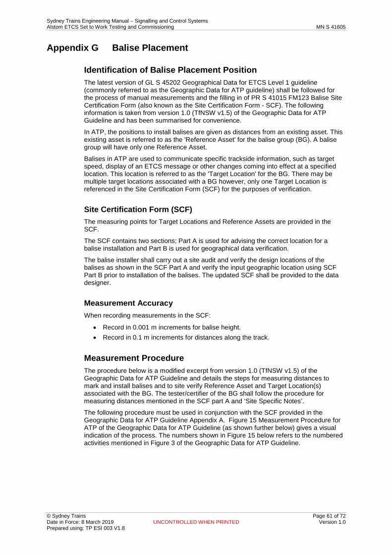
Sydney Trains Engineering Manual – Signalling and Control Systems Alstom ETCS Set to Work Testing and Commissioning MN S 41605
© Sydney Trains Page 61 of 72 Date in Force: 8 March 2019 UNCONTROLLED WHEN PRINTED Version 1.0 Prepared using: TP ESI 003 V1.8
Appendix G Balise Placement
Identification of Balise Placement Position The latest version of GL S 45202 Geographical Data for ETCS Level 1 guideline (commonly referred to as the Geographic Data for ATP guideline) shall be followed for the process of manual measurements and the filling in of PR S 41015 FM123 Balise Site Certification Form (also known as the Site Certification Form - SCF). The following information is taken from version 1.0 (TfNSW v1.5) of the Geographic Data for ATP Guideline and has been summarised for convenience.
In ATP, the positions to install balises are given as distances from an existing asset. This existing asset is referred to as the 'Reference Asset' for the balise group (BG). A balise group will have only one Reference Asset.
Balises in ATP are used to communicate specific trackside information, such as target speed, display of an ETCS message or other changes coming into effect at a specified location. This location is referred to as the 'Target Location' for the BG. There may be multiple target locations associated with a BG however, only one Target Location is referenced in the Site Certification Form (SCF) for the purposes of verification.
Site Certification Form (SCF) The measuring points for Target Locations and Reference Assets are provided in the SCF.
The SCF contains two sections; Part A is used for advising the correct location for a balise installation and Part B is used for geographical data verification.
The balise installer shall carry out a site audit and verify the design locations of the balises as shown in the SCF Part A and verify the input geographic location using SCF Part B prior to installation of the balises. The updated SCF shall be provided to the data designer.
Measurement Accuracy When recording measurements in the SCF:
• Record in 0.001 m increments for balise height. • Record in 0.1 m increments for distances along the track.
Measurement Procedure The procedure below is a modified excerpt from version 1.0 (TfNSW v1.5) of the Geographic Data for ATP Guideline and details the steps for measuring distances to mark and install balises and to site verify Reference Asset and Target Location(s) associated with the BG. The tester/certifier of the BG shall follow the procedure for measuring distances mentioned in the SCF part A and ‘Site Specific Notes’.
The following procedure must be used in conjunction with the SCF provided in the Geographic Data for ATP Guideline Appendix A. Figure 15 Measurement Procedure for ATP of the Geographic Data for ATP Guideline (as shown further below) gives a visual indication of the process. The numbers shown in Figure 15 below refers to the numbered activities mentioned in Figure 3 of the Geographic Data for ATP Guideline.
Sydney Trains Engineering Manual – Signalling and Control Systems Alstom ETCS Set to Work Testing and Commissioning MN S 41605
© Sydney Trains Page 62 of 72 Date in Force: 8 March 2019 UNCONTROLLED WHEN PRINTED Version 1.0 Prepared using: TP ESI 003 V1.8
: Measurement Procedure for ATP Figure 15
1. Identify the Reference Asset on site and identify the measurement point on the asset as detailed in Section 7 of the Geographic Data for ATP Guideline. Mark the measurement point if required to maintain accuracy of the measurements.
2. Identify the location perpendicular to the measurement points on the nearest rail of the designated track (the track associated with the Reference) as shown in Figure 15 above of the Geographic Data for ATP Guideline. Mark the position of the rail if required to maintain accuracy of measurement.
3. Measure out the distance from the Reference Asset to each of the balises in the balise group as specified in the SCF Part A.
4. If the distance falls in between two sleepers, identify the nearest sleeper suitable to install the balise (where applicable). ASDO calibration balise shall be installed at the designed position.
Various mounting options exists for installation of balises, both on sleeper and between sleepers; refer to SPG 0706 Installation of Trackside Equipment and the M05-500 series of construction drawings for further information.
Ensure the balises meet all restrictions applicable, as specified in ASA Signalling Design Principle – ETCS Level 1 and the M05-500 series of construction drawings.
5. Mark the balise locations and install the balises and update SCF Part A accordingly. When marking the balise locations use appropriate marking equipment to mark both the sleeper (where applicable) and the side of the rail.
The below steps 6 to 11 are for site verification of Reference Assets and Target Locations only and related to SCF Part B. Generally they would only be carried out at the same time as marking the balise locations, refer to section 6.3 of the Geographic Data for ATP Guideline for further information.
6. Identify the OHWSs on either side of the Reference Asset and confirm they are the same as those OHWSs mentioned in the SCF Part B using their labels as identification. Find the measuring points for these OHWSs as detailed in section 7 of the Geographic Data for ATP Guideline, which is associated with the survey pin located on the OHWS or the vertical centreline of the structure. Identify the location perpendicular to the measuring points on the nearest rail.
7. Measure distances between the Reference Asset and the OHWSs on either side of the nearest rail and record these in the actual fields in SCF Part B.

Sydney Trains Engineering Manual – Signalling and Control Systems Alstom ETCS Set to Work Testing and Commissioning MN S 41605
© Sydney Trains Page 63 of 72 Date in Force: 8 March 2019 UNCONTROLLED WHEN PRINTED Version 1.0 Prepared using: TP ESI 003 V1.8
8. Identify the OHWSs on either side of the Target Asset and confirm they are the same as those OHWSs mentioned in the SCF Part B using their labels as identification. Find the measuring points for these OHWSs as detailed in section 7 of the Geographic Data for ATP Guideline, which is associated with the survey pin located on the OHWS or the vertical centreline of the structure. Identify the location perpendicular to the measuring points on the nearest rail.
Measure distances between the Target Asset and the OHWSs on either side of along the nearest rail and record these in the actual fields in SCF Part B.
9. For controlled balise, measure and record the distance from balise position zero (0) to the identified IRJ/TU replacement point and update SCF Part A accordingly.
10. For controlled balise at a platform, measure and record the distance from balise position zero (0) to the platform stopping location and update SCF Part A accordingly.
Measurement Tools The tools to be used for the measurement of geographic data for ATP must satisfy the following:
• The tools must not interfere with the signalling system, e.g. short-circuit track circuits.
• The tools used must be safe to be used within the vicinity of the 1500V DC overhead wires. Tape measures shall be non-metallic.
• Measuring wheels shall be designed for top of rail application and be calibrated with a minimum accuracy of +/-1%.
• The tool(s) used, it’s precision and calibration date (if applicable) must be recorded in the SCF.
Key Constraints & Information 1. Standard construction drawings M05-500 series provide balise installation details
and in particular, drawings: M05-501, 502, 544, 545, 548, 569 and 558.
2. For balise placement design information, refer to standard drawings:
– M05-503 for balise general acceptance rules – M05-507 for generic placement rules of balises at a signal – M05-512 for generic placement rules of balises at a platform
3. Refer to MN S 41605 FM06 Balise Group Inspection and Testing Checklist (ITF ATP2).
The above listings are not necessarily a full set of reference documents.
Construction Standards Documents: Access to:
• M05-500 series of standard construction drawings • EGG 1656 - Balise Placement and Metal Mass Assessment Guide • SPG 0705 - Construction of Cable Routes and Signalling Civil Works • SPG 0706 - Installation of Trackside Equipment • SPG 0707 - Installation of Equipment Racks and Termination of Cables and Wiring • SPG 0708 - Small Buildings and Location Cases

Sydney Trains Engineering Manual – Signalling and Control Systems Alstom ETCS Set to Work Testing and Commissioning MN S 41605
© Sydney Trains Page 64 of 72 Date in Force: 8 March 2019 UNCONTROLLED WHEN PRINTED Version 1.0 Prepared using: TP ESI 003 V1.8
Other Documents: Access to:
• Applicable Circuit Book • Applicable Signalling Plan • GL S 45202 Geographical Data for ETCS Level 1 Guideline • MN S 41604 - Alstom ETCS Trackside Maintenance Manual • PR S 47110 - Inspection and Testing of Signalling • Applicable Test and Inspection Forms
Sydney Trains Engineering Manual – Signalling and Control Systems Alstom ETCS Set to Work Testing and Commissioning MN S 41605
© Sydney Trains Page 65 of 72 Date in Force: 8 March 2019 UNCONTROLLED WHEN PRINTED Version 1.0 Prepared using: TP ESI 003 V1.8
Appendix H LEU and Balise Validation Activities Important: The activities detailed in this Appendix are used to validate that the correct version of the data has been installed on site. The person undertaking these validation activities shall be totally independent of the data installation (programming) and data testing (verification) activities, and hence must be someone other than the Data Design Team, ETCS Programmer or ETCS Verifier.
Items required for LEU Configuration Key and Balise Data Validation:
1. MN S 41015 FM125 ETCS IDF1 - ETCS Installed Data Form (LEU Configuration Key).
2. MN S 41015 FM124 ETCS IDF2 - ETCS Installed Data Form (Balise).
3. ETCS Test Certificates (MN S 41605).
4. ETCS Data Release Note / Validation Report.
Validating the LEU Configuration Key and Balise Data: 1. Compare the CRCs entered on to the ETCS Installed Data Forms (ETCS IDF1/2)
and the Test Certificates by the ETCS Verifier with all of the balise and LEU CRCs generated in the Validation Report issued by the Data Design team.
2. If the CRCs are identical, check the mission reports to ensure that the ETCS Programmer and the ETCS Verifier have completed their missions successfully.
3. Complete the MN S 41605 FM02 Balise Group Test Certificates (TC ATP2) and MN S 41605 FM01 LEU Test Certificates (TC ATP1), by filling in the ‘OK’ status for the corresponding balise or LEU.
Actions Required If Validation is Unsuccessful: If the two CRCs are not identical, the data installation and verification has been unsuccessful, and the problem must be solved before commissioning can proceed. The suggested steps to resolve this are as follows:
1. Check the Test Certificates to see if all of the data written for that LEU or balise is correct according to the ETCS Installed Data Form (ETCS IDF1/2) (including the data version).
2. Check that the CRC data entered onto the ETCS Installed Data Forms (ETCS IDF1/2) by the ETCS Verifier agrees with the ETCS Data Release Note / Validation Report.
3. Arrange for the LEU or balise data to be re-installed and re-verified using a different BEPT to help narrow down the cause of the problem.
Note: The safety process relies on the independent check of the CRC by the Verifier and the Validator. The commissioning is not considered complete until the Validation activities are undertaken.
Sydney Trains Engineering Manual – Signalling and Control Systems Alstom ETCS Set to Work Testing and Commissioning MN S 41605
© Sydney Trains Page 66 of 72 Date in Force: 8 March 2019 UNCONTROLLED WHEN PRINTED Version 1.0 Prepared using: TP ESI 003 V1.8
Appendix I SIGEVENT Record Analysis
LEU Logs An LEU has an internal memory log to record the changes of state of LEU inputs balise telegrams produced. The last 10,000 “signalling events” and "system events" are stored, and these can be retrieved and analysed using a text editor such as Windows Notepad.
Downloading SigEvent and SysEvent Logs 1. Connect the BEPT to Ethernet port 1 (the maintenance port) of the LEU to be
analysed, using the supplied LEU/BEPT adaptor cable (this has a standard RJ45 connector on one end and M12 connector on the other end). The cable should be connected to Ethernet port 1 on the LEU, as shown.
2. Log in to the BEPT as the ETCS Programming Manager or Programmer or Verifier.
3. Under the [Cobalt Management] menu, select the [Maintenance Table Reading] function.
4. Under [Directory] select the desired file location on the USB memory stick for downloading the SigEvent and SysEvent logs.
5. If the Cobalt type is not pre-selected, under the “Cobalt Type Detection” window / screen, select [OK].
6. The [Cobalt Type] should be detected and displayed as [µCoder]. If the Cobalt type [????????] is displayed, check the Ethernet connection as above, and select [Refresh].
7. Select [SigEvent] and / or [SysEvent] as the tables to be uploaded, and under [Upload Type] select either [Total] or [Partial], depending on how many records you need to analyse.
8. Select the [Read] button to start the upload operation. When the upload operation is complete and there is no error, a message of confirmation will appear below the [Read] button.
9. The downloaded SigEvent and SysEvent Logs can be read on the BEPT by selecting the required log file from the drop down box under the [Read] button and message of confirmation, or the USB memory stick can be removed and the log files read using a PC and Windows Notepad.
Interpreting the SigEvent Log One binary (BIN) file and one text (TXT) file will be created for each LEU output (i.e. each balise controlled by the LEU), containing all events from the corresponding SigEvent table. These files will be created with the following name format, where (n) is either “1” or “2” depending upon the LEU output / balise:
“YYYY_MM_DD_HH_MM_SS_SIGEVENT(n).txt”.
The text file can be opened and read in any text viewer, such as Windows Notepad.
Figure 6 below is an example of an exported SigEvent Log file opened in Windows Notepad, showing the results when the LEU was reset (the date and time is reset to midnight on 01/01/1984 and parameter data to 0):
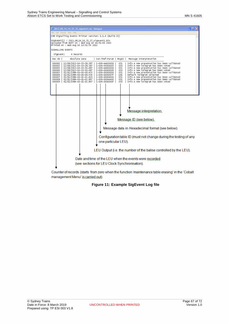
Sydney Trains Engineering Manual – Signalling and Control Systems Alstom ETCS Set to Work Testing and Commissioning MN S 41605
© Sydney Trains Page 67 of 72 Date in Force: 8 March 2019 UNCONTROLLED WHEN PRINTED Version 1.0 Prepared using: TP ESI 003 V1.8
Figure 11: Example SigEvent Log file
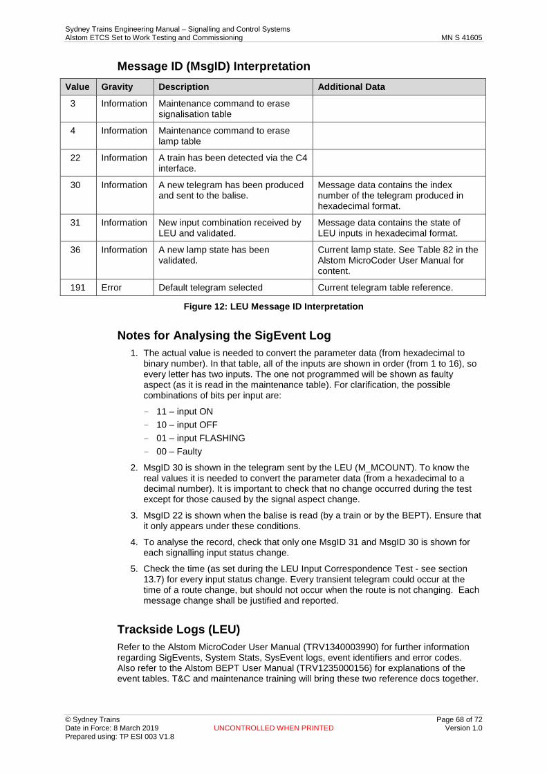
Sydney Trains Engineering Manual – Signalling and Control Systems Alstom ETCS Set to Work Testing and Commissioning MN S 41605
© Sydney Trains Page 68 of 72 Date in Force: 8 March 2019 UNCONTROLLED WHEN PRINTED Version 1.0 Prepared using: TP ESI 003 V1.8
Message ID (MsgID) Interpretation Value Gravity Description Additional Data
3 Information Maintenance command to erase signalisation table
4 Information Maintenance command to erase lamp table
22 Information A train has been detected via the C4 interface.
30 Information A new telegram has been produced and sent to the balise.
Message data contains the index number of the telegram produced in hexadecimal format.
31 Information New input combination received by LEU and validated.
Message data contains the state of LEU inputs in hexadecimal format.
36 Information A new lamp state has been validated.
Current lamp state. See Table 82 in the Alstom MicroCoder User Manual for content.
191 Error Default telegram selected Current telegram table reference.
Figure 12: LEU Message ID Interpretation
Notes for Analysing the SigEvent Log 1. The actual value is needed to convert the parameter data (from hexadecimal to
binary number). In that table, all of the inputs are shown in order (from 1 to 16), so every letter has two inputs. The one not programmed will be shown as faulty aspect (as it is read in the maintenance table). For clarification, the possible combinations of bits per input are:
– 11 – input ON – 10 – input OFF – 01 – input FLASHING – 00 – Faulty
2. MsgID 30 is shown in the telegram sent by the LEU (M_MCOUNT). To know the real values it is needed to convert the parameter data (from a hexadecimal to a decimal number). It is important to check that no change occurred during the test except for those caused by the signal aspect change.
3. MsgID 22 is shown when the balise is read (by a train or by the BEPT). Ensure that it only appears under these conditions.
4. To analyse the record, check that only one MsgID 31 and MsgID 30 is shown for each signalling input status change.
5. Check the time (as set during the LEU Input Correspondence Test - see section 13.7) for every input status change. Every transient telegram could occur at the time of a route change, but should not occur when the route is not changing. Each message change shall be justified and reported.
Trackside Logs (LEU) Refer to the Alstom MicroCoder User Manual (TRV1340003990) for further information regarding SigEvents, System Stats, SysEvent logs, event identifiers and error codes. Also refer to the Alstom BEPT User Manual (TRV1235000156) for explanations of the event tables. T&C and maintenance training will bring these two reference docs together.

Sydney Trains Engineering Manual – Signalling and Control Systems Alstom ETCS Set to Work Testing and Commissioning MN S 41605
© Sydney Trains Page 69 of 72 Date in Force: 8 March 2019 UNCONTROLLED WHEN PRINTED Version 1.0 Prepared using: TP ESI 003 V1.8
Appendix J LEU Precautions This appendix covers certain precautions that T&C personnel should be aware of with regards to LEUs. These precautions are detailed further in the Alstom ETCS Trackside Maintenance Manual. Figure 7 below shows the LEU interfaces referred to in these precautions.
Figure 13: LEU Interfaces
Important Note: Prior to replacing an LEU, first check that the new LEU is of the same or later hardware and firmware version.
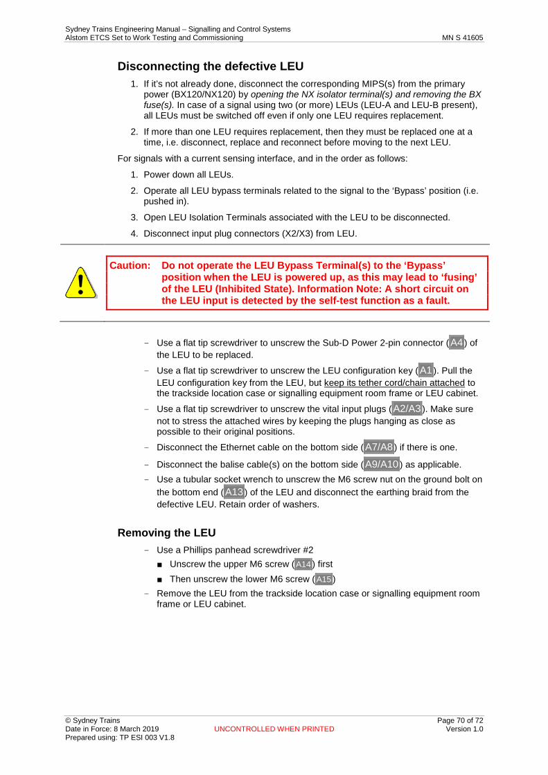
Sydney Trains Engineering Manual – Signalling and Control Systems Alstom ETCS Set to Work Testing and Commissioning MN S 41605
© Sydney Trains Page 70 of 72 Date in Force: 8 March 2019 UNCONTROLLED WHEN PRINTED Version 1.0 Prepared using: TP ESI 003 V1.8
Disconnecting the defective LEU 1. If it’s not already done, disconnect the corresponding MIPS(s) from the primary
power (BX120/NX120) by opening the NX isolator terminal(s) and removing the BX fuse(s). In case of a signal using two (or more) LEUs (LEU-A and LEU-B present), all LEUs must be switched off even if only one LEU requires replacement.
2. If more than one LEU requires replacement, then they must be replaced one at a time, i.e. disconnect, replace and reconnect before moving to the next LEU.
For signals with a current sensing interface, and in the order as follows:
1. Power down all LEUs.
2. Operate all LEU bypass terminals related to the signal to the ‘Bypass’ position (i.e. pushed in).
3. Open LEU Isolation Terminals associated with the LEU to be disconnected.
4. Disconnect input plug connectors (X2/X3) from LEU.
Caution: Do not operate the LEU Bypass Terminal(s) to the ‘Bypass’ position when the LEU is powered up, as this may lead to ‘fusing’ of the LEU (Inhibited State). Information Note: A short circuit on the LEU input is detected by the self-test function as a fault.
– Use a flat tip screwdriver to unscrew the Sub-D Power 2-pin connector ( A4 ) of the LEU to be replaced.
– Use a flat tip screwdriver to unscrew the LEU configuration key ( A1 ). Pull the LEU configuration key from the LEU, but keep its tether cord/chain attached to the trackside location case or signalling equipment room frame or LEU cabinet.
– Use a flat tip screwdriver to unscrew the vital input plugs ( A2/A3 ). Make sure not to stress the attached wires by keeping the plugs hanging as close as possible to their original positions.
– Disconnect the Ethernet cable on the bottom side ( A7/A8 ) if there is one.
– Disconnect the balise cable(s) on the bottom side ( A9/A10 ) as applicable. – Use a tubular socket wrench to unscrew the M6 screw nut on the ground bolt on
the bottom end ( A13 ) of the LEU and disconnect the earthing braid from the defective LEU. Retain order of washers.
Removing the LEU – Use a Phillips panhead screwdriver #2
■ Unscrew the upper M6 screw ( A14 ) first ■ Then unscrew the lower M6 screw ( A15 )
– Remove the LEU from the trackside location case or signalling equipment room frame or LEU cabinet.
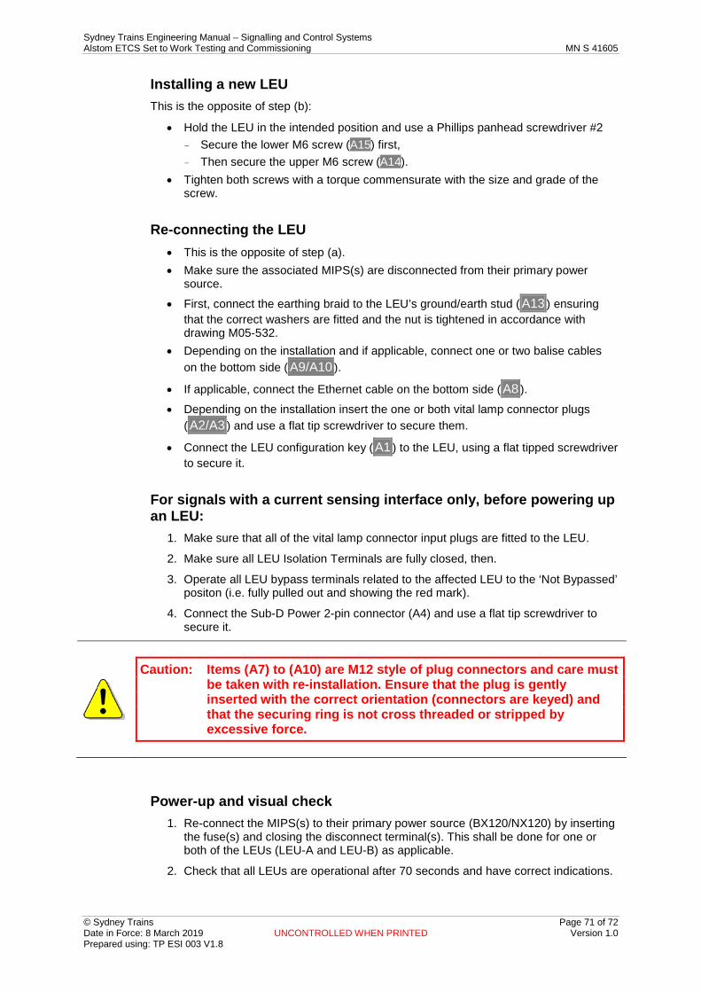
Sydney Trains Engineering Manual – Signalling and Control Systems Alstom ETCS Set to Work Testing and Commissioning MN S 41605
© Sydney Trains Page 71 of 72 Date in Force: 8 March 2019 UNCONTROLLED WHEN PRINTED Version 1.0 Prepared using: TP ESI 003 V1.8
Installing a new LEU This is the opposite of step (b):
• Hold the LEU in the intended position and use a Phillips panhead screwdriver #2 – Secure the lower M6 screw (A15) first, – Then secure the upper M6 screw (A14).
• Tighten both screws with a torque commensurate with the size and grade of the screw.
Re-connecting the LEU • This is the opposite of step (a). • Make sure the associated MIPS(s) are disconnected from their primary power
source.
• First, connect the earthing braid to the LEU’s ground/earth stud ( A13 ) ensuring that the correct washers are fitted and the nut is tightened in accordance with drawing M05-532.
• Depending on the installation and if applicable, connect one or two balise cables on the bottom side ( A9/A10 ).
• If applicable, connect the Ethernet cable on the bottom side ( A8 ).
• Depending on the installation insert the one or both vital lamp connector plugs ( A2/A3 ) and use a flat tip screwdriver to secure them.
• Connect the LEU configuration key ( A1 ) to the LEU, using a flat tipped screwdriver to secure it.
For signals with a current sensing interface only, before powering up an LEU:
1. Make sure that all of the vital lamp connector input plugs are fitted to the LEU.
2. Make sure all LEU Isolation Terminals are fully closed, then.
3. Operate all LEU bypass terminals related to the affected LEU to the ‘Not Bypassed’ positon (i.e. fully pulled out and showing the red mark).
4. Connect the Sub-D Power 2-pin connector (A4) and use a flat tip screwdriver to secure it.
Caution: Items (A7) to (A10) are M12 style of plug connectors and care must be taken with re-installation. Ensure that the plug is gently inserted with the correct orientation (connectors are keyed) and that the securing ring is not cross threaded or stripped by excessive force.
Power-up and visual check 1. Re-connect the MIPS(s) to their primary power source (BX120/NX120) by inserting
the fuse(s) and closing the disconnect terminal(s). This shall be done for one or both of the LEUs (LEU-A and LEU-B) as applicable.
2. Check that all LEUs are operational after 70 seconds and have correct indications.
Sydney Trains Engineering Manual – Signalling and Control Systems Alstom ETCS Set to Work Testing and Commissioning MN S 41605
© Sydney Trains Page 72 of 72 Date in Force: 8 March 2019 UNCONTROLLED WHEN PRINTED Version 1.0 Prepared using: TP ESI 003 V1.8
For signals with a current sensing interface only: Make sure all LEU bypass terminals related to the signal (for each LEU if there are more than one) are operated to the ‘Not Bypassed’ position (i.e. fully pulled out and showing the red mark) before powering up the LEUs. Check that the correct signal aspect is displayed.
Caution: Failure to operate all LEU bypass terminals to the ‘Not Bypassed’ position, prior to powering up the LEU may lead to ‘fusing’ of the LEU. Information Note: A short circuit on the LEU input is detected by the self-test function, as a fault.