Mini weather station OMC-938/939 - Observator · Obsermet division OMC-938/939 Manual 1. General...
25
Mini weather station OMC-938/939 Users Manual Ver. No. 1.04 OBSERVATOR instruments B.V. P.O.Box 60 2980 AB Ridderkerk Rietdekkerstraat 6 2984 BM Ridderkerk Tel. ++31 (0)180 463411 Telefax ++31 (0)180-463510 The Netherlands
Transcript of Mini weather station OMC-938/939 - Observator · Obsermet division OMC-938/939 Manual 1. General...

Mini weather station
OMC-938/939
Users ManualVer. No. 1.04
OBSERVATOR instruments B.V.P.O.Box 602980 AB RidderkerkRietdekkerstraat 62984 BM RidderkerkTel. ++31 (0)180 463411Telefax ++31 (0)180-463510The Netherlands
Obsermet division OMC-938/939 Manual
Contents
1. General . . . . . . . . . . . . . . . . . . . . . . . . . . . . . . . . . . . . . . . . . . . . . . . . . . . . . . . . . . . . . . 2
2. Installation . . . . . . . . . . . . . . . . . . . . . . . . . . . . . . . . . . . . . . . . . . . . . . . . . . . . . . . . . . . . 32.1. Mechanical . . . . . . . . . . . . . . . . . . . . . . . . . . . . . . . . . . . . . . . . . . . . . . . . . . . . . 32.2. Electrical . . . . . . . . . . . . . . . . . . . . . . . . . . . . . . . . . . . . . . . . . . . . . . . . . . . . . . 3
2.2.1 General cable layout . . . . . . . . . . . . . . . . . . . . . . . . . . . . . . . . . . . . . . . 32.2.2 Power supply settings . . . . . . . . . . . . . . . . . . . . . . . . . . . . . . . . . . . . . . 42.2.3. Connections . . . . . . . . . . . . . . . . . . . . . . . . . . . . . . . . . . . . . . . . . . . . . 52.2.4. Daisy chaining . . . . . . . . . . . . . . . . . . . . . . . . . . . . . . . . . . . . . . . . . . . 6
3. Commissioning . . . . . . . . . . . . . . . . . . . . . . . . . . . . . . . . . . . . . . . . . . . . . . . . . . . . . . . . . 73.1 Communication and ports . . . . . . . . . . . . . . . . . . . . . . . . . . . . . . . . . . . . . . . . . . . 8
3.1.1 Serial input output Port 1 . . . . . . . . . . . . . . . . . . . . . . . . . . . . . . . . . . . . 83.1.2 Serial input output Port 2 . . . . . . . . . . . . . . . . . . . . . . . . . . . . . . . . . . . . 93.1.3 Serial input output Port 3 . . . . . . . . . . . . . . . . . . . . . . . . . . . . . . . . . . . . 103.1.4 Serial input output Port 4 . . . . . . . . . . . . . . . . . . . . . . . . . . . . . . . . . . . 113.1.5 Serial input output Port 5 . . . . . . . . . . . . . . . . . . . . . . . . . . . . . . . . . . . . 123.1.6 Analogue input output Port 6 . . . . . . . . . . . . . . . . . . . . . . . . . . . . . . . . . 133.2 Message format . . . . . . . . . . . . . . . . . . . . . . . . . . . . . . . . . . . . . . . . . . . . 14
3.3 Settings via frontpanel . . . . . . . . . . . . . . . . . . . . . . . . . . . . . . . . . . . . . . . . . . . . . 153.3.1 Units and averaging settings . . . . . . . . . . . . . . . . . . . . . . . . . . . . . . . . . 153.3.2 Lamp test . . . . . . . . . . . . . . . . . . . . . . . . . . . . . . . . . . . . . . . . . . . . . . . 153.3.3 Selection minimum/maximum wind . . . . . . . . . . . . . . . . . . . . . . . . . . . . . 153.3.4 Deviation setting . . . . . . . . . . . . . . . . . . . . . . . . . . . . . . . . . . . . . . . . . . 15
3.4 Settings possible via the RS232 port. . . . . . . . . . . . . . . . . . . . . . . . . . . . . . . . . . . 16
4. Maintenance . . . . . . . . . . . . . . . . . . . . . . . . . . . . . . . . . . . . . . . . . . . . . . . . . . . . . . . . . . . 174.1 Uploading a new software version in the OMC-938 display unit . . . . . . . . . . . . . . . 17
5. Setup via RS232 port on rear of instrument . . . . . . . . . . . . . . . . . . . . . . . . . . . . . . . . . . . . 185.1 Select input device . . . . . . . . . . . . . . . . . . . . . . . . . . . . . . . . . . . . . . . . . . . . . . . 185.2 Select output device . . . . . . . . . . . . . . . . . . . . . . . . . . . . . . . . . . . . . . . . . . . . . . 215.3 Set averaging of channels . . . . . . . . . . . . . . . . . . . . . . . . . . . . . . . . . . . . . . . . . . 225.4 Device options . . . . . . . . . . . . . . . . . . . . . . . . . . . . . . . . . . . . . . . . . . . . . . . . . . . 235.5 Show all settings . . . . . . . . . . . . . . . . . . . . . . . . . . . . . . . . . . . . . . . . . . . . . . . . . 24
Page 1

Obsermet division OMC-938/939 Manual
1. General
The Obsermet mini weather station display OMC-938 is a combined display for wind speed andwind direction and four other parameters. The OMC-938 is provided with a digital LED indicator forspeed, and a double ring of 36 LED’s actual and average direction information and four 5 digitsdisplays.
A second three digit display located in the lower right corner provides gust information.
The front panel is provided with three buttons for adjusting the brightness of the LED’s. testing allthe LED display’s and entering a set menu for adjusting display settings.
The OMC-938 will accept the output-signals directly from the series OMC-182 and OMC-183 signalconditionings units, without the need of additional interfaces. The display provide "daisy-chain"connections for additional indicators. As an option, the OMC-938 can provide analogue outputsignals for wind speed and direction. Those can be 4...20 mA or 0...1 volt.
The display is housed in a 288x144 mm. DIN-size casing suitable for flush mounting in a console,or display panel. Unit depth is 63 mm.
The signal transmission of the daisy chain is: 20mA current loop, 1200 ... 9600 Baud, ASCII-code.
The OMC-938 can display the wind speed in various scales i.e. Miles per hour (mph). Meters persecond (m/s). Knots. kilometers per hour (km/h) and Beaufort. In addition the analogue output forwind speed and direction can be transmitted using a variety of averaging periods between 1 and600 seconds.
Principle characteristics.
Power supply : 220Vac. 115Vac and 24Vdc selectable via wire bridgesPower supply optional : 12 VdcSpeed display : 3 digit 7 segment LED display 14.3 mm heightGust display : 3 digit 7 segment LED display 10.1 mm heightParameter displays : 5 digit 7 segment LED display 14.3 mm heightDirection display : 36 LED’s circular color REDDirection average : 36 LED’s circular color AMBERInput signals : Currentloop or RS422 with ASCII informationOutput : Daisy chainOutput (optional) : 0...1 volt. 4...20 mA, RS232 and NMEA-183Dimensions : 288x144x94 mmWeight : approx. 1200 grScale : Knots, mph. m/s or km/hBrightness control : From the front panel (optional on distance)Readout units : m/s, Km/h, knots, Mph and Bft
Page 2

Obsermet division OMC-938/939 Manual
2. Installation
2.1. Mechanical
Panel mounting of the OMC-938 display requires a panel cut-out of 282mm x 137mm square.Maximum panel thickness 5 mm. Rear access must be provided, for fixing of the tightening clampsand connecting the electric cabling. The depth of the unit is 63 mm and an additional clearance of 8mm should be allowed for the cable connections.
2.2. Electrical
All Obsermet displays utilize a common terminal strip for the connections to the wind sensors andthe ancillary displays and/or recorders. The signal cable between the conversion unit and thedisplay is a 2-core cable for signal transmission. To reduce interference the cable must have acommon screen. This screen should be grounded to earth in the junction box of the wind sensor. Inthis way the cable may run distances up to 1 kilometer.
Recommended cable: 1 twisted pairs with common screen, core size 0.75 mm2.
In the case that the wind sensor is provided with a heater. 2 extra cores are required for powersupply to the heater. The size of the heater cable depends on the cable length. (For more detailssee manual wind sensor)
The OMC-938 display unit can provide the 15 Volts DC. power supply to the microprocessortransmitter in the wind sensor. The power consumption of the sensor transmitter electronics isapprox. 65 mA. This power supply should not be used for the optional heaters in the sensor. Thesesensor-heaters must be powered independently from the display unit.
2.2.1 General cable layout
A typical cable layout is shown in thedrawing shown on the right. TheOMC-938/939 will always receive itinformation from a signalconditionings unit.
This signal conditionings unit isconnected to all the sensors installedto the system. It converts all theinformation into a digital output string.
This information string is transmittedevery second to the OMC-938/939.
If more than four sensors areconnected to the signal conditioningsunit a secundairy display is addedwho can also display four sensorparameters.
If a barometric pressure sensor isconnected to the signal conditioningsunit the unit can calculate the QFEand the QNH if needed.
Page 3
Obsermet division OMC-938/939 Manual
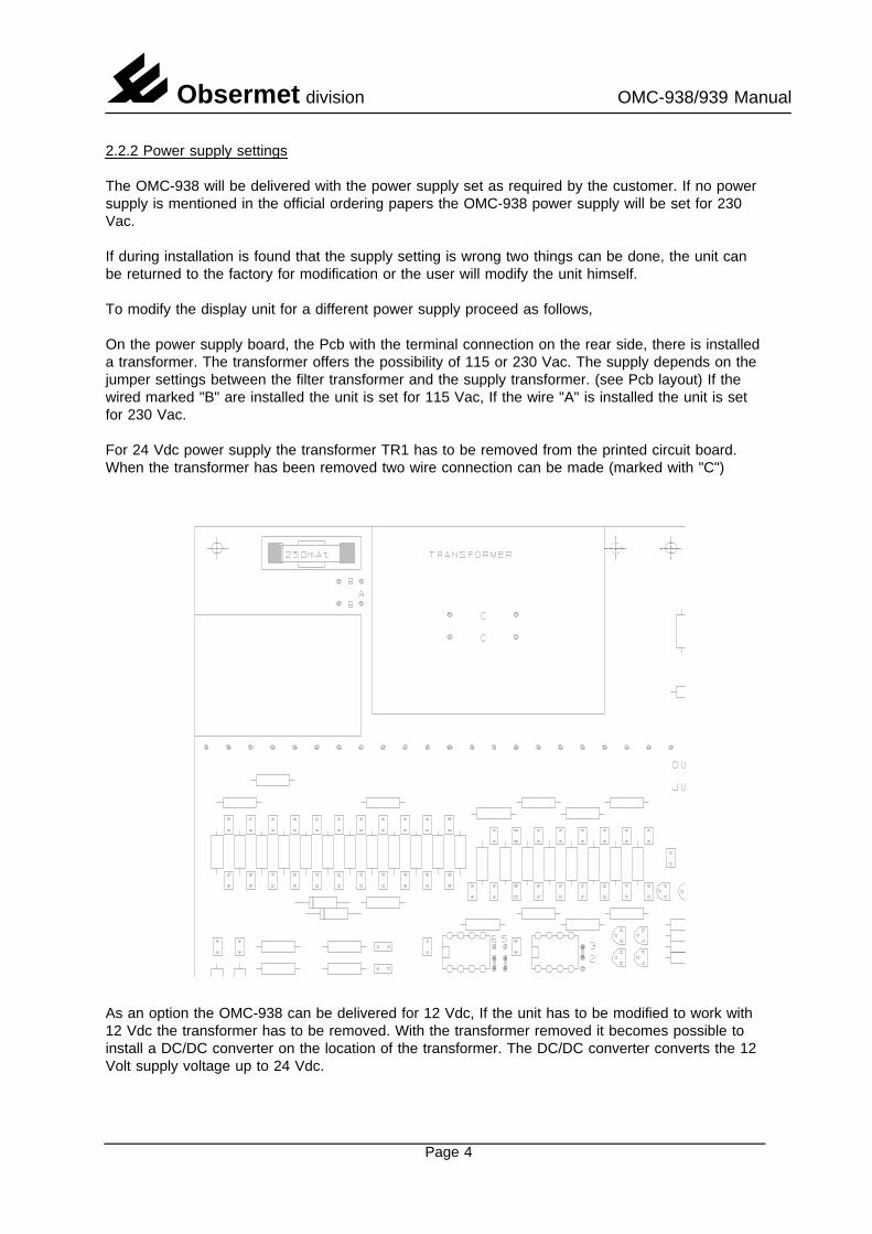
2.2.2 Power supply settings
The OMC-938 will be delivered with the power supply set as required by the customer. If no powersupply is mentioned in the official ordering papers the OMC-938 power supply will be set for 230Vac.
If during installation is found that the supply setting is wrong two things can be done, the unit canbe returned to the factory for modification or the user will modify the unit himself.
To modify the display unit for a different power supply proceed as follows,
On the power supply board, the Pcb with the terminal connection on the rear side, there is installeda transformer. The transformer offers the possibility of 115 or 230 Vac. The supply depends on thejumper settings between the filter transformer and the supply transformer. (see Pcb layout) If thewired marked "B" are installed the unit is set for 115 Vac, If the wire "A" is installed the unit is setfor 230 Vac.
For 24 Vdc power supply the transformer TR1 has to be removed from the printed circuit board.When the transformer has been removed two wire connection can be made (marked with "C")
As an option the OMC-938 can be delivered for 12 Vdc, If the unit has to be modified to work with12 Vdc the transformer has to be removed. With the transformer removed it becomes possible toinstall a DC/DC converter on the location of the transformer. The DC/DC converter converts the 12Volt supply voltage up to 24 Vdc.
Page 4
Obsermet division OMC-938/939 Manual
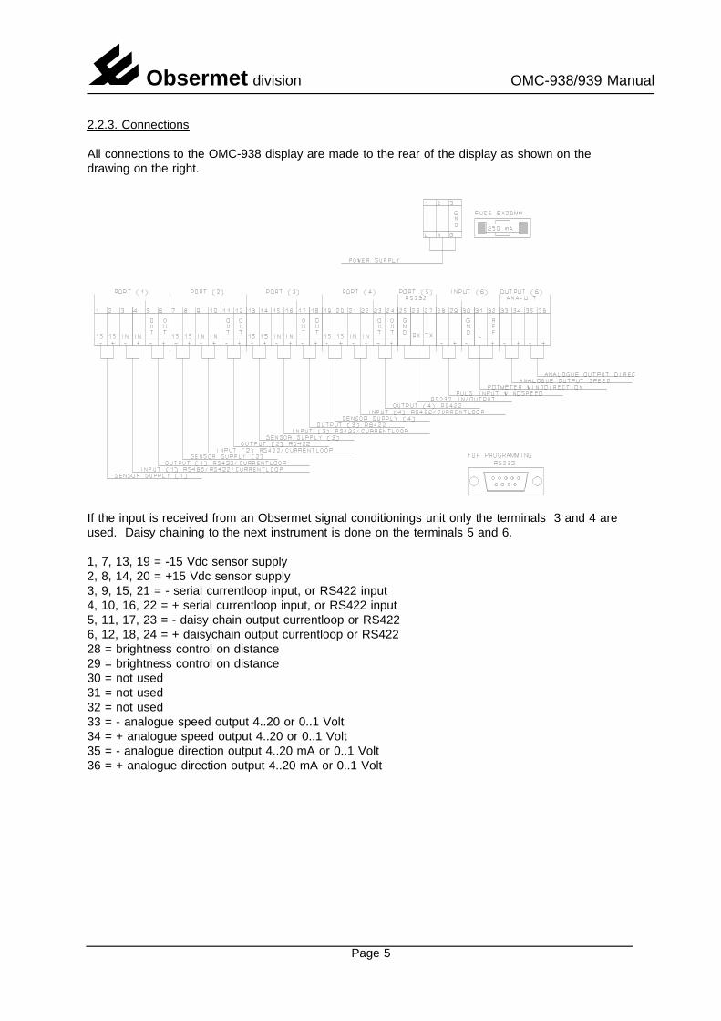
2.2.3. Connections
All connections to the OMC-938 display are made to the rear of the display as shown on thedrawing on the right.
If the input is received from an Obsermet signal conditionings unit only the terminals 3 and 4 areused. Daisy chaining to the next instrument is done on the terminals 5 and 6.
1, 7, 13, 19 = -15 Vdc sensor supply2, 8, 14, 20 = +15 Vdc sensor supply3, 9, 15, 21 = - serial currentloop input, or RS422 input4, 10, 16, 22 = + serial currentloop input, or RS422 input5, 11, 17, 23 = - daisy chain output currentloop or RS4226, 12, 18, 24 = + daisychain output currentloop or RS42228 = brightness control on distance29 = brightness control on distance30 = not used31 = not used32 = not used33 = - analogue speed output 4..20 or 0..1 Volt34 = + analogue speed output 4..20 or 0..1 Volt35 = - analogue direction output 4..20 mA or 0..1 Volt36 = + analogue direction output 4..20 mA or 0..1 Volt
Page 5
Obsermet division OMC-938/939 Manual
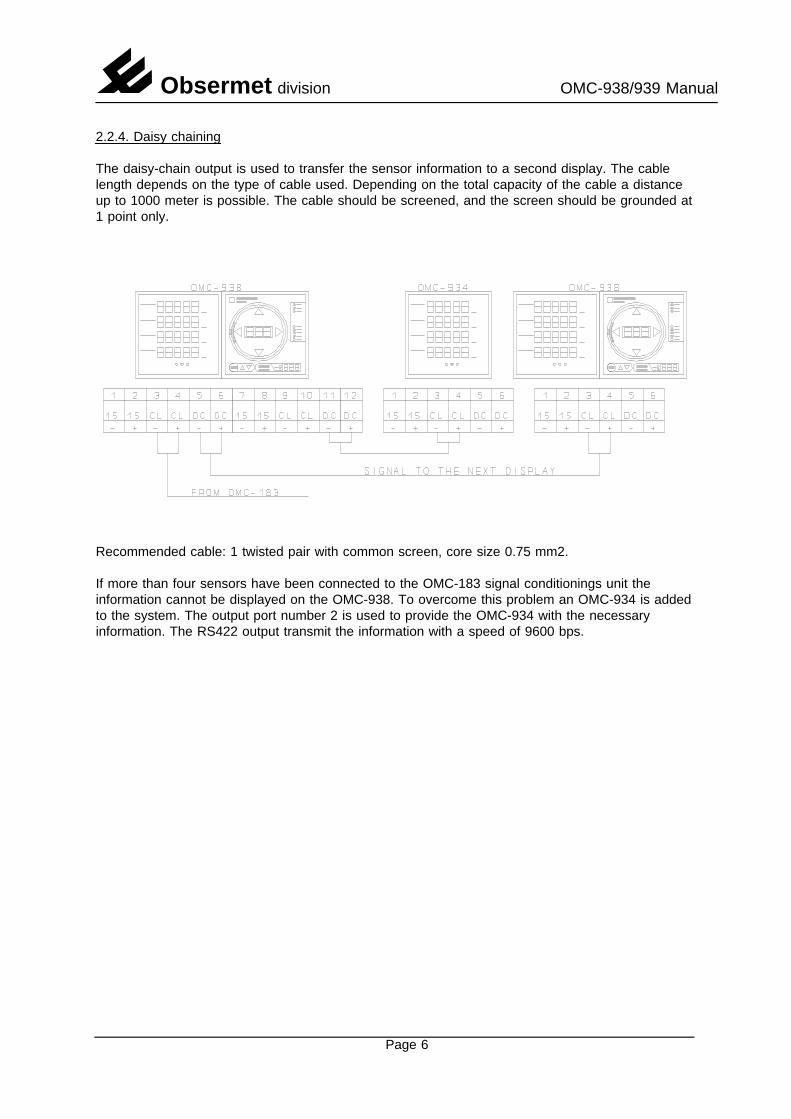
2.2.4. Daisy chaining
The daisy-chain output is used to transfer the sensor information to a second display. The cablelength depends on the type of cable used. Depending on the total capacity of the cable a distanceup to 1000 meter is possible. The cable should be screened, and the screen should be grounded at1 point only.
Recommended cable: 1 twisted pair with common screen, core size 0.75 mm2.
If more than four sensors have been connected to the OMC-183 signal conditionings unit theinformation cannot be displayed on the OMC-938. To overcome this problem an OMC-934 is addedto the system. The output port number 2 is used to provide the OMC-934 with the necessaryinformation. The RS422 output transmit the information with a speed of 9600 bps.
Page 6
Obsermet division OMC-938/939 Manual
3. Commissioning
Before switching ON the mains, check that the power supply is correct as indicated on theidentification label on the rear of the equipment.
With no signal cable connected, switch on the display and observe the front panel LED,s. Thesystem will perform a led test all led are switched on and off one by one. When the test is finishedthe display shows on the led circle no information and on all displays only "---" is shown. This isbecause no sensor information is received by the display.
With all cabling correctly connected, the display will show all the information received from theOMC-183.
Adjustment cannot be made as the sensor-signal is digitally transmitted.
When the display is fully operational and the and the sensor information is not received for morethan 5 seconds the display starts flashing indicating that the sensor information is not longerreceived by the display unit.
If from the speed display inside the led circle the decimal point between the hundred and the tendisplay is ON the Eeprom has been damaged. Settings for proper operation are most probably lost.The display must be returned to the factory.
Displaying QFE and QNH
On the display often the calculate value QFE and QNH is shown.
QFE is defined as the barometric pressure corresponding to the official height of the airfield.QNH is defined as the barometric pressure corresponding to mean sealevel.
The calculation for QFE and QNH is done in the OMC-183 signal conditionings, P1 gives the QFEvalue and P2 the QNH value.
The scalings factors S1 and S2 are used for airfield height and sensor height.S1 = Sensor height in relation with the airfeld or helideckS2 = Height airfield or helideck in relation with main sealevel
The calculate values P1 and P2 are transmitted to the OMC-938 with the indents F for QFE and Nfor QNH. The values are transmitted by the OMC-183 with one digit behind the decimal point.
Page 7
Obsermet division OMC-938/939 Manual
3.1 Communication and ports
The OMC-938/939 has 6 input and output ports available. The first 4 inputs are normally used forthe Obsermet windsensors working with a currentloop output signal or signals from the obsermetsignal conditioning units. For other purposes a RS422 input is also possible. Port number 1 canalso be set for a RS485 input signal.
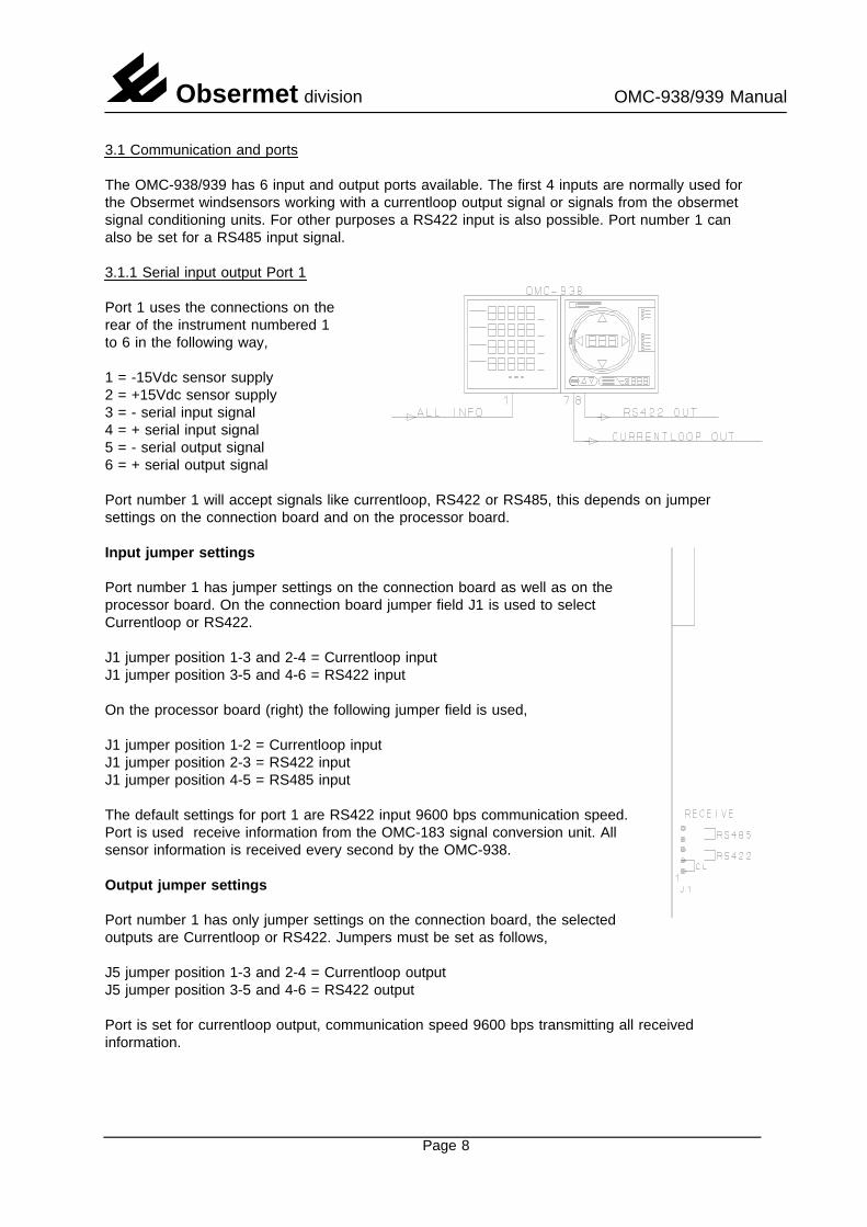
3.1.1 Serial input output Port 1
Port 1 uses the connections on therear of the instrument numbered 1to 6 in the following way,
1 = -15Vdc sensor supply2 = +15Vdc sensor supply3 = - serial input signal4 = + serial input signal5 = - serial output signal6 = + serial output signal
Port number 1 will accept signals like currentloop, RS422 or RS485, this depends on jumpersettings on the connection board and on the processor board.
Input jumper settings
Port number 1 has jumper settings on the connection board as well as on theprocessor board. On the connection board jumper field J1 is used to selectCurrentloop or RS422.
J1 jumper position 1-3 and 2-4 = Currentloop inputJ1 jumper position 3-5 and 4-6 = RS422 input
On the processor board (right) the following jumper field is used,
J1 jumper position 1-2 = Currentloop inputJ1 jumper position 2-3 = RS422 inputJ1 jumper position 4-5 = RS485 input
The default settings for port 1 are RS422 input 9600 bps communication speed.Port is used receive information from the OMC-183 signal conversion unit. Allsensor information is received every second by the OMC-938.
Output jumper settings
Port number 1 has only jumper settings on the connection board, the selectedoutputs are Currentloop or RS422. Jumpers must be set as follows,
J5 jumper position 1-3 and 2-4 = Currentloop outputJ5 jumper position 3-5 and 4-6 = RS422 output
Port is set for currentloop output, communication speed 9600 bps transmitting all receivedinformation.
Page 8
Obsermet division OMC-938/939 Manual
3.1.2 Serial input output Port 2
Port 2 uses the connections on the rear of the instrument numbered 7 to 12 in the following way,
7 = -15Vdc sensor supply8 = +15Vdc sensor supply9 = - serial input signal10 = + serial input signal11 = - serial output signal12 = + serial output signal
Port number 2 will accept signals like currentloop and RS422, this depends on jumper settings onthe connection board.
Input jumper settings
Port number 2 has only jumper settings on the connection board. On the connection board jumperfield J2 and J6 is used to select Currentloop or RS422.
J2 jumper position 1-3 and 2-4 = Currentloop inputJ2 jumper position 3-5 and 4-6 = RS422 inputJ6 jumper position 1-2 = RS422J6 jumper position 2-3 = Currentloop
The input of port 2 is not used in this configuration.
Output jumper settings
There are no jumper settings available. The output on port 2 can only be RS422.
The output of port 2 is used to transmitting the received information (RS422) to a second slavedisplay which is used as the number of sensors, connected to the OMC-183, is more than four. Thecommunication speed is set to 9600 bps.
Page 9
Obsermet division OMC-938/939 Manual
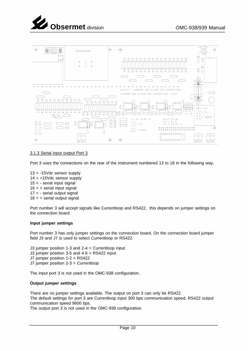
3.1.3 Serial input output Port 3
Port 3 uses the connections on the rear of the instrument numbered 13 to 18 in the following way,
13 = -15Vdc sensor supply14 = +15Vdc sensor supply15 = - serial input signal16 = + serial input signal17 = - serial output signal18 = + serial output signal
Port number 3 will accept signals like Currentloop and RS422, this depends on jumper settings onthe connection board.
Input jumper settings
Port number 3 has only jumper settings on the connection board. On the connection board jumperfield J3 and J7 is used to select Currentloop or RS422.
J3 jumper position 1-3 and 2-4 = Currentloop inputJ3 jumper position 3-5 and 4-6 = RS422 inputJ7 jumper position 1-2 = RS422J7 jumper position 2-3 = Currentloop
The input port 3 is not used in the OMC-938 configuration.
Output jumper settings
There are no jumper settings available. The output on port 3 can only be RS422.The default settings for port 3 are Currentloop input 300 bps communication speed, RS422 outputcommunication speed 9600 bps.The output port 3 is not used in the OMC-938 configuration.
Page 10
Obsermet division OMC-938/939 Manual
3.1.4 Serial input output Port 4
Port 4 uses the connections on the rear of the instrument numbered 7 to 12 in the following way,
19 = -15Vdc sensor supply20 = +15Vdc sensor supply21 = - serial input signal22 = + serial input signal23 = - serial output signal24 = + serial output signal
Port number 4 will accept signals like currentloop and RS422, this depends on jumper settings onthe connection board.
Input jumper settings
Port number 4 has only jumper settings on the connection board. On the connection board jumperfield J4 and J8 is used to select Currentloop or RS422.
J4 jumper position 1-3 and 2-4 = Currentloop inputJ4 jumper position 3-5 and 4-6 = RS422 inputJ8 jumper position 1-2 = RS422J8 jumper position 2-3 = Currentloop
The input port 4 is not used in the OMC-938 configuration.
Output jumper settings
There are no jumper settings available. The output on port 4 can only be RS422.
The default settings for port 4 are Currentloop input 300 bps communication speed, RS422 outputcommunication speed 9600 bps.
The output port 4 is not used in the OMC-938 configuration.
Page 11
Obsermet division OMC-938/939 Manual
3.1.5 Serial input output Port 5
Port 5 uses the connections on the rear of the instrument numbered 25 to 27 in the following way,
25 = Ground signal26 = Receive data27 = Transmit data
Port number 5 will accept only RS232 signals.
Within the menu driven software, input or output can be set to transmit or receive data on this port.
There are no jumper settings available for input or output port number 5
The default settings for port 5 are RS232 input and output, communication speed 9600 bps.
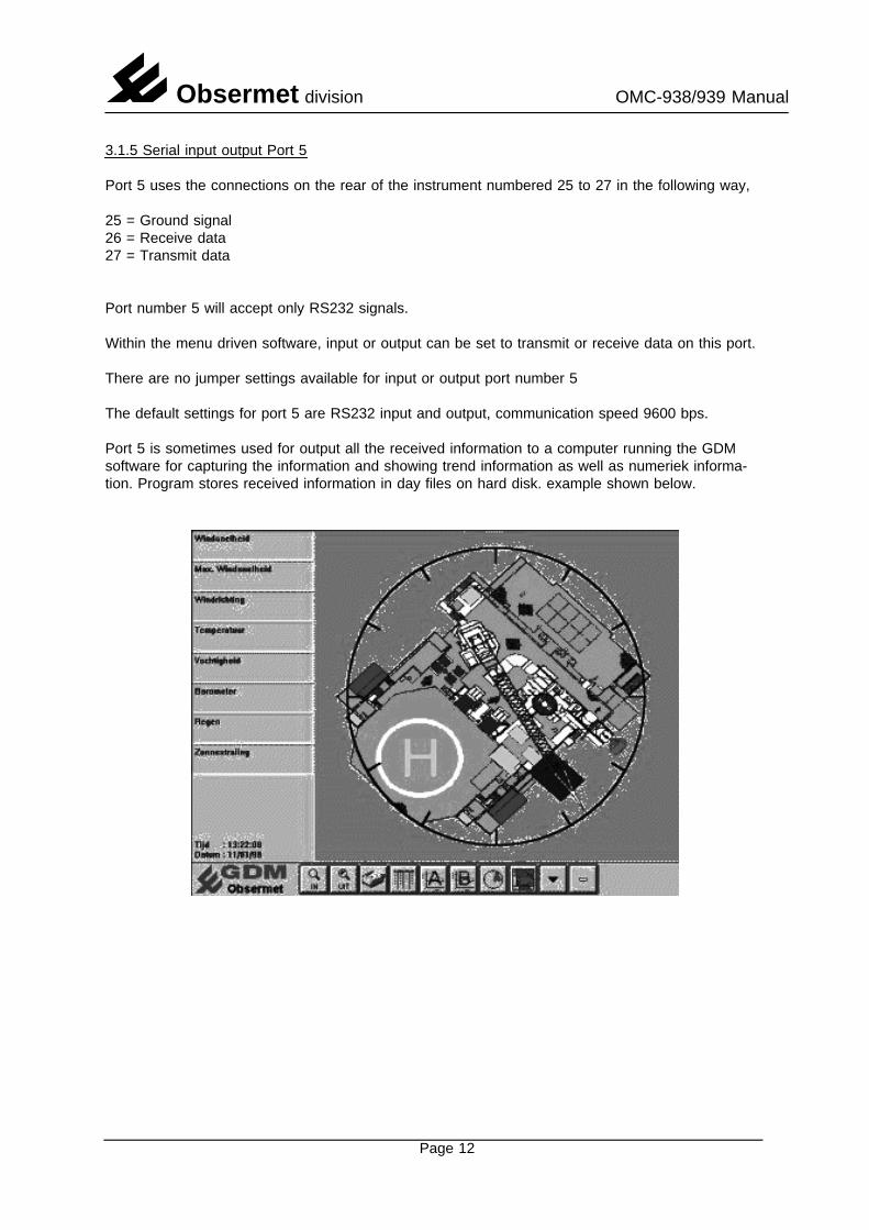
Port 5 is sometimes used for output all the received information to a computer running the GDMsoftware for capturing the information and showing trend information as well as numeriek informa-tion. Program stores received information in day files on hard disk. example shown below.
Page 12
Obsermet division OMC-938/939 Manual
3.1.6 Analogue input output Port 6
Port 6 is completely different used as the ports 1 to 5. The input of port 6 accept signals from ananalogue windsensor system providing a pulse for wind speed and an potmeter output signal forwind direction. The output port 6 are two analogue signals coupled to one of the input and providing0...1 Volt or 4...20 mA over a set range.
Port 6 input
Port 6 uses the connections on the rear of the instrument numbered 28 to 32 inthe following way,
28 = - input pulse wind speed29 = + input pulse wind speed30 = common signal potentiometer31 = wiper potentiometer32 = + reference signal 2.7 Volts
As analogue input is optional the IC’s needed are standard not installed in thesockets. If analogue is needed the IC’s 14 and 15 must be placed in thesockets.
Port 6 output
The OMC-938 provides two analogue output signal which can be coupled toany of the received information. This is optional and not as standard available.
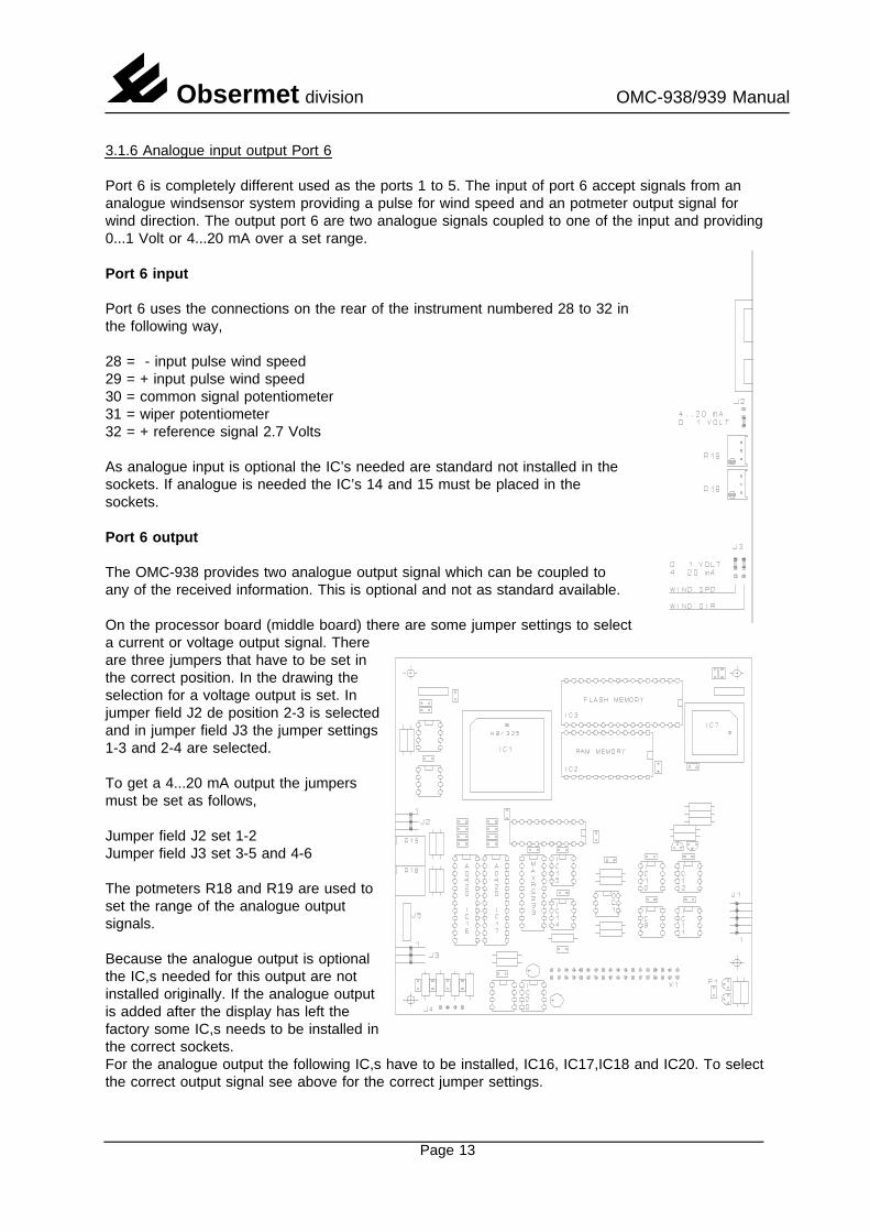
On the processor board (middle board) there are some jumper settings to selecta current or voltage output signal. Thereare three jumpers that have to be set inthe correct position. In the drawing theselection for a voltage output is set. Injumper field J2 de position 2-3 is selectedand in jumper field J3 the jumper settings1-3 and 2-4 are selected.
To get a 4...20 mA output the jumpersmust be set as follows,
Jumper field J2 set 1-2Jumper field J3 set 3-5 and 4-6
The potmeters R18 and R19 are used toset the range of the analogue outputsignals.
Because the analogue output is optionalthe IC,s needed for this output are notinstalled originally. If the analogue outputis added after the display has left thefactory some IC,s needs to be installed inthe correct sockets.For the analogue output the following IC,s have to be installed, IC16, IC17,IC18 and IC20. To selectthe correct output signal see above for the correct jumper settings.
Page 13
Obsermet division OMC-938/939 Manual
3.2 Message format
Currentloop output OMC-160 message format
The currentloop output is normally used to transport the collected data from the currentloop input.Using the system in this way it is not necessary anymore to output the data as analogue signalswhich upgrade the performance and the accuracy. The data is transmitted with the same speed asdata is received from the windsensor. 300 baud 8N1.
If the currentloop output signal from the OMC-160 is repeated by the OMC-138 the message looksas follows,
<LF>D125<sp>V234<sp >cscs<CR>
In the above message the transmitted wind direction is the number shown after the indent "D" 125degrees. the windspeed in the message is shown after the indent "V" 234 is 23.4 m/s. Thewindspeed is transmitted without decimal point and must therefor be divided by 10 to get the correctwindspeed.
The checksum is all information in the string added, the least significant byte is divided into highand low nibble and both nibbles are incremented by hexadecimal 30. This information is sent out asa checksum.
OMC-2900 message format
Sometimes the data is transmitted in the OMC-2900 format. This format is used when moreparameters are transmitted.
The wind data transported in the OMC-2900 format looks as following,
<STX> <LF>V21.2<SP>CSCS< CR><LF>D156<SP>CSCS<CR> <EOT>
Every message starts with a start of text character after this the messages are transmitted. Allmessages start with a line feed followed with the identifier for the data, then the data and then achecksum for protection reasons, the message end with a carriage return.
All input channels can be transmitted in this way every second to any receiving station.
RS232/RS422 in/output channel
The OMC-2900 and the OMC-160 format on the RS232/RS422 looks the same as the format usedin the currentloop output described paragraph 3.2.2.2
There are two possibilities to transmit data in the NMEA output, windspeed can be transmitted inm/s or in knots, both messages are shown below.
SIIMWV.I 23.R.5.8.N.A*24 Windspeed in knotsSIIMWV.1 23.R.5.8.M.A*27 Windspeed in meters per seconds
Page 14
Obsermet division OMC-938/939 Manual
3.3 Settings via frontpanel
On the frontpanel of the display there are three pushbuttons. The buttons are marked "MENU",arrow up and arrow down. Under normal conditions the buttons marked arrow up and down areused to adjust the brightness of the display.
3.3.1 Units and averaging settings
When the menu button is pressed the led in the average time window starts flashing indicating thatthe select option is on. It becomes possible now to make a selection using the arrow up and downbutton. If the menu button is pressed again the led in the units window starts flashing indicating thatthe select option is on. With the arrow up and down button it is possible now to select different unitsfor the windspeed.
When the buttons are not touched for 5 seconds the display will return to the normal operationmode.
3.3.2 Lamp test
With both arrow buttons pressed all the displays and led’s start flashing (lamp test) When theinterval time for gust is set to 0 seconds the Gust must be reset manually. this has to be done bypressing the menu and the arrow down button at the same time.
3.3.3 Selection minimum/maximum wind
The display provide the possibility to use the gust display to show minimum or maximumwindspeed. Selection is possible with the menu button. Press the menu button and the led in frontof max wind starts flashing, press the button up and the led switches over to min wind. After 10seconds the display automatically jumps back to max wind speed.
3.3.4 Deviation setting
The display provide the possibility to add an offset to the wind direction. This is very useful for wind-systems installed on oilrigs and for airports if they want to use the magnetic North instead of thetrue North.
An offset is added in the following way, Press the arrow-up button and the Menu button, the Gustdisplay starts flashing and is showing the offset. As long as the display is flashing the offset can bechanged using the arrow-up or arrow-down buttons. The set value is added to the actual windinformation from the sensor.
Page 15

Obsermet division OMC-938/939 Manual
3.4 Settings possible via the RS232 port.
1 Users interval time, 3 different times can be set, direction, speed and gust. When for gust atime of 0 is selected the gust can be reseted by pushing the menu button and the arrowdown button at the same time.
2 Scaling analogue outputs. For the analogue outputs it is possible to set the span of thesignal. 4...20 mA can be 0...40 m/s or 50 m/s. For the direction a choice can be madebetween 360 or 540 or 720 degrees.
3 Average time for analogue output signals, For the 2 available analogue outputs it is possibleto set a average time. This is done to prevent analogue recorder to paint the paper.
4 Selection of sensor type, a selection can be made between the following inputs.
a. Obsermet sensors OMC-160. OMC-170 and OMC-165 (standard)b. Gill sensors RS422 (optional)c. Irdam sensor RS422 (optional)d. Vector pulse/potmeter (optional)
5 When pulse/potmeter is selected it is possible to set the scaling factors for the input signals.
6 RS232 output on/off and baudrate setting
7 RS422 output on/off and baudrate setting
8 Repeat the sensor message on the RS232/422 or select NMEA-183 output signal.
9 The display provide the possibility to add an offset to the wind direction. This is very usefulfor wind-systems installed on oilrigs and for airports if they want to use the magnetic Northinstead of the true North.
An offset is added in the following way, Press the arrow-up button and the Menu button, theGust display starts flashing and is showing the offset. As long as the display is flashing theoffset can be changed using the arrow-up or arrow-down buttons. The set value is added tothe actual wind information from the sensor.
Page 16

Obsermet division OMC-938/939 Manual
4. Maintenance
The Obsermet OMC-138/139 digital display unit has no moving parts, and requires no routinemaintenance. If required, the perspex display front can be cleaned with a cloth, slightly moistenedwith a soft detergent. Care must be taken that no liquid enters the display unit. Solvents should notbe used, and scratches should be avoided.
Fuses: Glass fuses 5x20 mm, 250mA for 230 Vac. 250mA for 115 Vac 250mA for 24 Vdc
The fuse can be reached as follows,
Switch of the main supply and disconnect all the wiring on the rear of the display.Remove the four 2.5 mm screws on the rear of the display.Remove the front window by pulling on a corner with both hands.With holding the front down, the whole case can be removed now.
The fuse can be reached now. The fuse is placed on the PCB where all the wires are connected to.
4.1 Uploading a new software version in the OMC-938 display unit
On the rear of the instrument there is a 9 pin D-connector. Connect to this connector a RS232serial cable wired from computer to computer (2 and 3 swapped). No handshake needed.
Start the Program Hyper terminal available in Windows 95’.Set terminal parameters to 9800 8N1Press the "enter bar", The following menu should appear.
OMC 938/939 Obsermet Mini weather display unitSoftware version 1.1 Serial nr : 93800001
1 - Select input device.2 - Select output device.3 - Set averaging of channels.4 - Set options.5 - Show all settings.6 - Test instrument.
If this menu appears on your screen a proper connection with the display has been established,cable, display and terminal program are working properly.
Close the program "Hyper terminal" and go to the DOS environment.
Go to the directory where the files "Upload" and the program "Flash.A20" can be found. If this isdone give the following command "Upload 1 flash.a20" (The "1" stands for the number of com port)Display will respond with the following messages,1. Program to upload motorola hex-files into the omc-138 and series2. Start erasing Flash eprom3. Flash is erased4. Start with upload and programming of flash5. 000000 !ACK! until 01C500 !ACK! (number of blocks depends on length of program)
The program has been downloaded and installed.The next thing to do is programming display parameters.
Page 17
Obsermet division OMC-938/939 Manual
5. Setup via RS232 port on rear of instrument
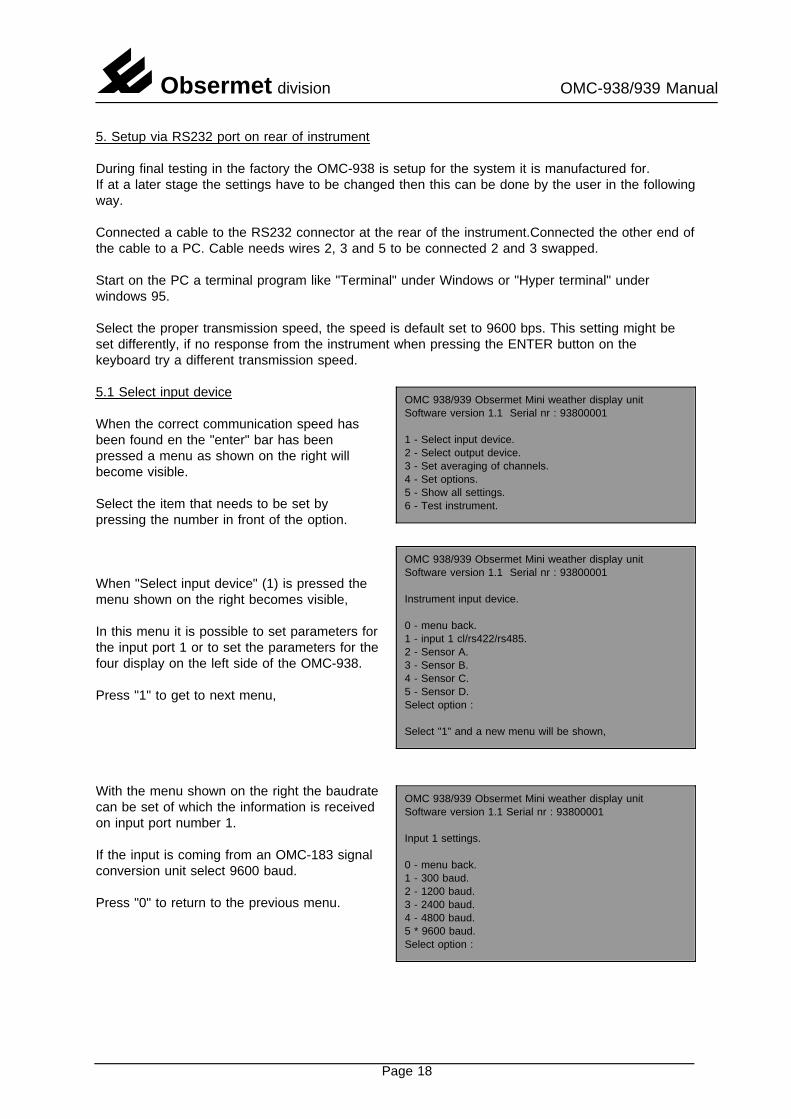
During final testing in the factory the OMC-938 is setup for the system it is manufactured for.If at a later stage the settings have to be changed then this can be done by the user in the followingway.
Connected a cable to the RS232 connector at the rear of the instrument.Connected the other end ofthe cable to a PC. Cable needs wires 2, 3 and 5 to be connected 2 and 3 swapped.
Start on the PC a terminal program like "Terminal" under Windows or "Hyper terminal" underwindows 95.
Select the proper transmission speed, the speed is default set to 9600 bps. This setting might beset differently, if no response from the instrument when pressing the ENTER button on thekeyboard try a different transmission speed.
OMC 938/939 Obsermet Mini weather display unitSoftware version 1.1 Serial nr : 93800001
1 - Select input device.2 - Select output device.3 - Set averaging of channels.4 - Set options.5 - Show all settings.6 - Test instrument.
5.1 Select input device
When the correct communication speed hasbeen found en the "enter" bar has beenpressed a menu as shown on the right willbecome visible.
Select the item that needs to be set bypressing the number in front of the option.
OMC 938/939 Obsermet Mini weather display unitSoftware version 1.1 Serial nr : 93800001
Instrument input device.
0 - menu back.1 - input 1 cl/rs422/rs485.2 - Sensor A.3 - Sensor B.4 - Sensor C.5 - Sensor D.Select option :
Select "1" and a new menu will be shown,
When "Select input device" (1) is pressed themenu shown on the right becomes visible,
In this menu it is possible to set parameters forthe input port 1 or to set the parameters for thefour display on the left side of the OMC-938.
Press "1" to get to next menu,
With the menu shown on the right the baudrateOMC 938/939 Obsermet Mini weather display unitSoftware version 1.1 Serial nr : 93800001
Input 1 settings.
0 - menu back.1 - 300 baud.2 - 1200 baud.3 - 2400 baud.4 - 4800 baud.5 * 9600 baud.Select option :
can be set of which the information is receivedon input port number 1.
If the input is coming from an OMC-183 signalconversion unit select 9600 baud.
Press "0" to return to the previous menu.
Page 18
Obsermet division OMC-938/939 Manual
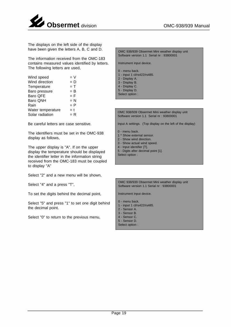
The displays on the left side of the display
OMC 938/939 Obsermet Mini weather display unitSoftware version 1.1 Serial nr : 93800001
Instrument input device.
0 - menu back.1 - input 1 cl/rs422/rs485.2 - Display A.3 - Display B.4 - Display C.5 - Display D.Select option :
have been given the letters A, B, C and D.
The information received from the OMC-183contains measured values identified by letters.
OMC 938/939 Obsermet Mini weather display unitSoftware version 1.1 Serial nr : 93800001
Input A settings. (Top display on the left of the display)
0 - menu back.1 * Show external sensor.2 - Show wind direction.3 - Show actual wind speed.4 - Input identifier [T].5 - Digits after decimal point [1].Select option :
The following letters are used,
Wind speed = VWind direction = DTemperature = TBaro pressure = BBaro QFE = FBaro QNH = NRain = PWater temperature = tSolar radiation = R
Be careful letters are case sensitive.
The identifiers must be set in the OMC-938display as follows,
The upper display is "A". If on the upperdisplay the temperature should be displayedthe identifier letter in the information stringreceived from the OMC-183 must be coupledto display "A"
Select "2" and a new menu will be shown,
OMC 938/939 Obsermet Mini weather display unitSoftware version 1.1 Serial nr : 93800001
Instrument input device.
0 - menu back.1 - input 1 cl/rs422/rs485.2 - Sensor A.3 - Sensor B.4 - Sensor C.5 - Sensor D.Select option :
Select "4" and a press "T",
To set the digits behind the decimal point,
Select "5" and press "1" to set one digit behindthe decimal point.
Select "0" to return to the previous menu,
Page 19
Obsermet division OMC-938/939 Manual
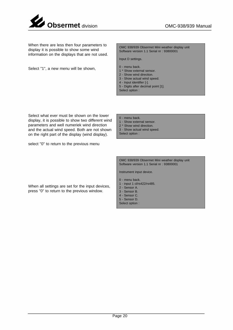
OMC 938/939 Obsermet Mini weather display unitSoftware version 1.1 Serial nr : 93800001
Input D settings.
0 - menu back.1 * Show external sensor.2 - Show wind direction.3 - Show actual wind speed.4 - Input identifier [-].5 - Digits after decimal point [1].Select option :
When there are less then four parameters todisplay it is possible to show some windinformation on the displays that are not used.
Select "1", a new menu will be shown,
0 - menu back.1 - Show external sensor.2 * Show wind direction.3 - Show actual wind speed.Select option :
Select what ever must be shown on the lowerdisplay, it is possible to show two different windparameters and well numeriek wind directionand the actual wind speed. Both are not shownon the right part of the display (wind display).
OMC 938/939 Obsermet Mini weather display unitSoftware version 1.1 Serial nr : 93800001
Instrument input device.
0 - menu back.1 - input 1 cl/rs422/rs485.2 - Sensor A.3 - Sensor B.4 - Sensor C.5 - Sensor D.Select option :
select "0" to return to the previous menu
When all settings are set for the input devices,press "0" to return to the previous window.
Page 20

Obsermet division OMC-938/939 Manual
5.2 Select output device
OMC 938/939 Obsermet Mini weather display unitSoftware version 1.1 Serial nr : 93800001
1 - Select input device.2 - Select output device.3 - Set averaging of channels.4 - Set options.5 - Show all settings.6 - Test instrument.
If the information received from the OMC-183is needed elsewhere the OMC-938 can be setto transmit the received information as acurrentloop signal or as a RS422 signal.
Output ports can be set as follows,
Select "2", a new window will be shown,
OMC 938/939 Obsermet Mini weather display unitSoftware version 1.1 Serial nr : 93800001
Instrument output device.
0 - menu back.1 - output 1 cl/rs422.2 - output 2 rs422.Select option :
Select "1" or "2" to go to the next window.
On output port 1 it is possible to selectcurrentloop or RS422 as an output signal.
Output port 2 can only be used for RS422output signals.
OMC 938/939 Obsermet Mini weather display unitSoftware version 1.1 Serial nr : 93800001
Output 1 settings. (CL/RS422)
0 - menu back.1 * 1200 baud.2 - 2400 baud.3 - 4800 baud.4 - 9600 baud.5 * Standard Obsermet message daisy chain6 - Special message on requestSelect option :
For output port 1 the choice must be madewith jumper settings on the printed circuitboards. The jumpers are set for currentloopoutput on port number 1.
Select a baudrate by pressing the correctnumber, press "0" to return to the previouswindow.
The format of the message should also beselected here. This will be normally the
OMC 938/939 Obsermet Mini weather display unitSoftware version 1.1 Serial nr : 93800001
Instrument output device.
0 - menu back.1 - output 1 cl/rs422.2 - output 2 rs422.Select option :
Obsermet message but on special customerrequest the message can be different. Whenthis is it must be selected here. Specialmessage could be the NMEA output format.
Select "0" to return to the previous window.
Page 21
Obsermet division OMC-938/939 Manual
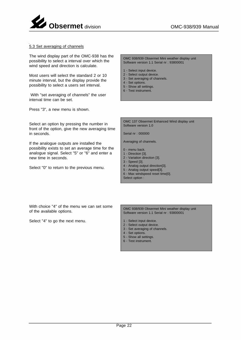
5.3 Set averaging of channels
OMC 938/939 Obsermet Mini weather display unitSoftware version 1.1 Serial nr : 93800001
1 - Select input device.2 - Select output device.3 - Set averaging of channels.4 - Set options.5 - Show all settings.6 - Test instrument.
The wind display part of the OMC-938 has thepossibility to select a interval over which thewind speed and direction is calculate.
Most users will select the standard 2 or 10minute interval, but the display provide thepossibility to select a users set interval.
With "set averaging of channels" the userinterval time can be set.
OMC 137 Obsermet Enhanced Wind display unitSoftware version 1.0
Serial nr : 000000
Averaging of channels.
0 - menu back.1 - Direction [3].2 - Variation direction [3].3 - Speed [3].4 - Analog output direction[3].5 - Analog output speed[3].6 - Max windspeed reset time[0].Select option :
Press "3", a new menu is shown.
Select an option by pressing the number in
OMC 938/939 Obsermet Mini weather display unitSoftware version 1.1 Serial nr : 93800001
1 - Select input device.2 - Select output device.3 - Set averaging of channels.4 - Set options.5 - Show all settings.6 - Test instrument.
front of the option, give the new averaging timein seconds.
If the analogue outputs are installed thepossibility exists to set an average time for theanalogue signal. Select "5" or "6" and enter anew time in seconds.
Select "0" to return to the previous menu.
With choice "4" of the menu we can set someof the available options.
Select "4" to go the next menu.
Page 22
Obsermet division OMC-938/939 Manual
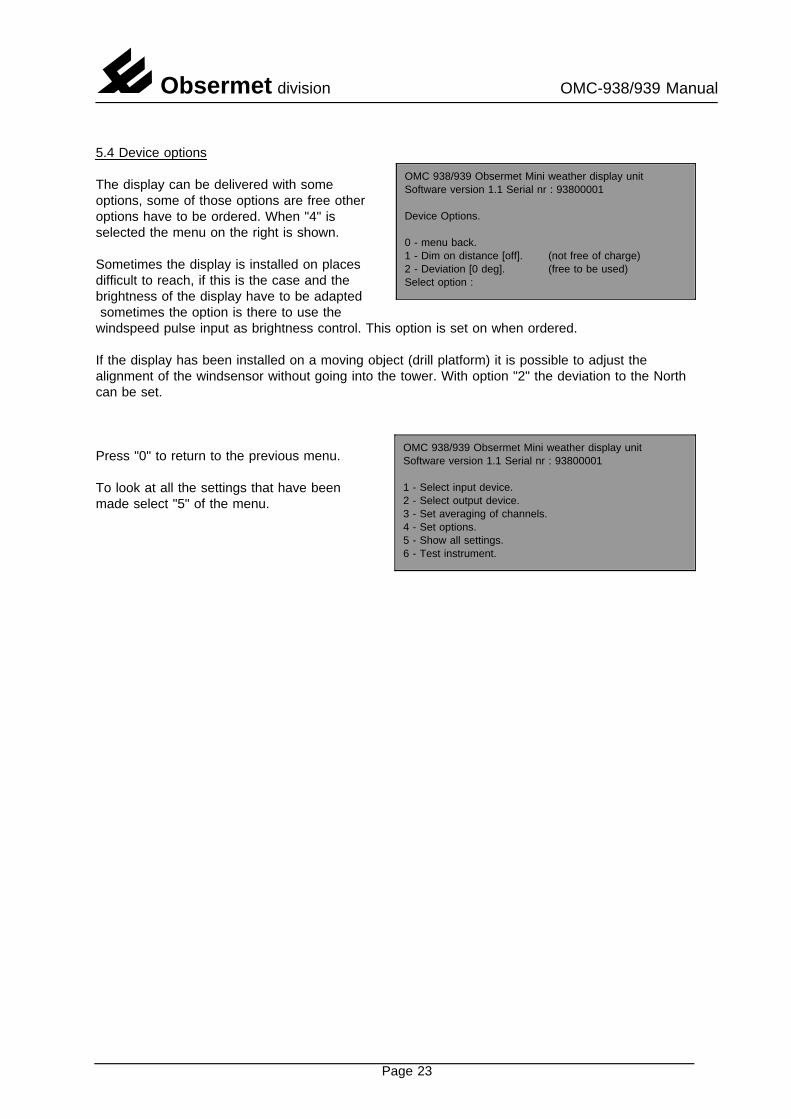
5.4 Device options
OMC 938/939 Obsermet Mini weather display unitSoftware version 1.1 Serial nr : 93800001
Device Options.
0 - menu back.1 - Dim on distance [off]. (not free of charge)2 - Deviation [0 deg]. (free to be used)Select option :
The display can be delivered with someoptions, some of those options are free otheroptions have to be ordered. When "4" isselected the menu on the right is shown.
Sometimes the display is installed on placesdifficult to reach, if this is the case and thebrightness of the display have to be adaptedsometimes the option is there to use the
windspeed pulse input as brightness control. This option is set on when ordered.
If the display has been installed on a moving object (drill platform) it is possible to adjust thealignment of the windsensor without going into the tower. With option "2" the deviation to the Northcan be set.
OMC 938/939 Obsermet Mini weather display unitSoftware version 1.1 Serial nr : 93800001
1 - Select input device.2 - Select output device.3 - Set averaging of channels.4 - Set options.5 - Show all settings.6 - Test instrument.
Press "0" to return to the previous menu.
To look at all the settings that have beenmade select "5" of the menu.
Page 23
Obsermet division OMC-938/939 Manual
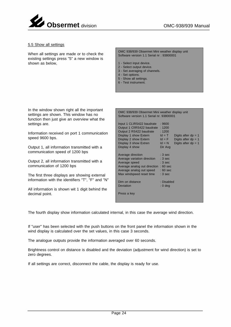
5.5 Show all settings
OMC 938/939 Obsermet Mini weather display unitSoftware version 1.1 Serial nr : 93800001
1 - Select input device.2 - Select output device.3 - Set averaging of channels.4 - Set options.5 - Show all settings.6 - Test instrument.
When all settings are made or to check theexisting settings press "5" a new window isshown as below,
OMC 938/939 Obsermet Mini weather display unitSoftware version 1.1 Serial nr. 93800001
Input 1 CL\RS422 baudrate : 9600Output 1 Cl\RS422 baudrate : 1200Output 2 RS422 baudrate : 1200Display 1 show Extern Id = T Digits after dp = 1Display 2 show Extern Id = F Digits after dp = 1Display 3 show Extren Id = N Digits after dp = 1Display 4 show Dir Avg
Average direction : 3 secAverage variation direction : 3 secAverage speed : 3 secAverage analog out direction : 60 secAverage analog out speed : 60 secMax windspeed reset time : 3 sec
Dim on distance : DisabledDeviation : 0 deg
Press a key
In the window shown right all the importantsettings are shown. This window has nofunction then just give an overview what thesettings are.
Information received on port 1 communicationspeed 9600 bps.
Output 1, all information transmitted with acommunication speed of 1200 bps
Output 2, all information transmitted with acommunication of 1200 bps
The first three displays are showing externalinformation with the identifiers "T", "F" and "N"
All information is shown wit 1 digit behind thedecimal point.
The fourth display show information calculated internal, in this case the average wind direction.
If "user" has been selected with the push buttons on the front panel the information shown in thewind display is calculated over the set values, in this case 3 seconds.
The analogue outputs provide the information averaged over 60 seconds.
Brightness control on distance is disabled and the deviation (adjustment for wind direction) is set tozero degrees.
If all settings are correct, disconnect the cable, the display is ready for use.
Page 24