MicroTech III Chiller Unit Controller Protocol...
42
Engineering Data ED 15121-4 Group: Controls Part Number: ED 15121-4 Date: April 2013 Supersedes: ED 15121-3 MicroTech ® III Chiller Unit Controller Protocol Information Modbus ® Protocol • Pathfinder ® Air-Cooled Chiller, Model AWS; with or without variable frequency drive (VFD) • Air-Cooled Scroll Chiller, Model AGZ-D © 2012 Daikin
Transcript of MicroTech III Chiller Unit Controller Protocol...

Engineering Data ED 15121-4 Group: Controls
Part Number: ED 15121-4
Date: April 2013
Supersedes: ED 15121-3
MicroTech® III Chiller Unit Controller Protocol Information
Modbus® Protocol
• Pathfinder® Air-Cooled Chiller, Model AWS; with or without variablefrequency drive (VFD)
• Air-Cooled Scroll Chiller, Model AGZ-D
© 2012 Daikin

Table of Contents TABLE OF CONTENTS ........................................................................................................................................................ 2
LIMITED WARRANTY ............................................................................................................................................................. 3 NOTICE .................................................................................................................................................................................. 3 REVISION HISTORY ................................................................................................................................................................ 4 SOFTWARE REVISION ............................................................................................................................................................. 4 REFERENCE DOCUMENTS ....................................................................................................................................................... 4
INTRODUCTION .................................................................................................................................................................... 5 CHILLER MODELS .................................................................................................................................................................. 5 CONTROLLER DATA POINTS .................................................................................................................................................. 5
MODBUS PROTOCOL INFORMATION ............................................................................................................................ 6 COMPATIBILITY ..................................................................................................................................................................... 6 PROTOCOL DEFINITIONS ........................................................................................................................................................ 6 VALID FUNCTION CODES ....................................................................................................................................................... 6 VALID ERROR CODES ............................................................................................................................................................ 7 MODBUS ADDRESSING ........................................................................................................................................................... 7 MODBUS DATA POINT ........................................................................................................................................................... 7 EXAMPLE DATA POINT: CHILLER ON/OFF ............................................................................................................................. 8 CONFIGURING THE UNIT CONTROLLER .................................................................................................................................. 8
TYPICAL APPLICATION: MINIMUM INTEGRATION ..................................................................................................... 9 DISPLAY IMPORTANT DATA POINTS ...................................................................................................................................... 9
PROTOCOL POINT SUMMARY ........................................................................................................................................10 DATA POINTS FOR CHILLER MODELS ...................................................................................................................................10 REGISTER MAPPING ..............................................................................................................................................................11 ALARM DATA POINTS ...........................................................................................................................................................19
DETAILED DATA POINT INFORMATION .......................................................................................................................24 ACTIVE CAPACITY LIMIT OUTPUT ........................................................................................................................................24 ACTIVE SETPOINT .................................................................................................................................................................24 ACTUAL CAPACITY ...............................................................................................................................................................24 ALARM DIGITAL OUTPUT .....................................................................................................................................................24 APPLICATION SOFTWARE VERSION .......................................................................................................................................25 CAPACITY LIMIT SETPOINT - NETWORK ...............................................................................................................................25 CHILLER CAPACITY LIMITED ................................................................................................................................................25 CHILLER CURRENT ...............................................................................................................................................................25 CHILLER ENABLE OUTPUT ....................................................................................................................................................26 CHILLER ENABLE SETPOINT .................................................................................................................................................26 CHILLER LOCAL/REMOTE .....................................................................................................................................................26 CHILLER LOCATION ..............................................................................................................................................................26 CHILLER MODE OUTPUT .......................................................................................................................................................26 CHILLER MODE SETPOINT - NETWORK .................................................................................................................................27 CHILLER MODEL ...................................................................................................................................................................27 CHILLER ON/OFF ..................................................................................................................................................................27 CHILLER STATUS ..................................................................................................................................................................27 CLEAR ALARMS - NETWORK.................................................................................................................................................27 COMPRESSOR CURRENT ........................................................................................................................................................28 COMPRESSOR DISCHARGE REFRIGERANT TEMPERATURE .....................................................................................................28 COMPRESSOR PERCENT RLA ................................................................................................................................................28 COMPRESSOR POWER ............................................................................................................................................................28 COMPRESSOR RUN HOURS ....................................................................................................................................................29 COMPRESSOR STARTS ...........................................................................................................................................................29 COMPRESSOR SUCTION REFRIGERANT TEMPERATURE .........................................................................................................29
2 ED 15121-4

COMPRESSOR VOLTAGE ....................................................................................................................................................... 30 CONDENSER REFRIGERANT PRESSURE ................................................................................................................................. 30 CONDENSER SATURATED REFRIGERANT TEMPERATURE ...................................................................................................... 30 COOL SETPOINT - NETWORK ................................................................................................................................................ 30 CURRENT DATE & TIME ....................................................................................................................................................... 31 EVAPORATOR ENTERING FLUID TEMPERATURE ................................................................................................................... 31 EVAPORATOR FLOW SWITCH STATUS .................................................................................................................................. 31 EVAPORATOR LEAVING FLUID TEMPERATURE ..................................................................................................................... 31 EVAPORATOR PUMP RUN HOURS ......................................................................................................................................... 31 EVAPORATOR PUMP STATUS ................................................................................................................................................ 32 EVAPORATOR REFRIGERANT PRESSURE ............................................................................................................................... 32 EVAPORATOR SATURATED REFRIGERANT TEMPERATURE ................................................................................................... 32 FAULT ALARM CODE ........................................................................................................................................................... 32 FAULT ALARM INDEX .......................................................................................................................................................... 32 ICE SETPOINT - NETWORK .................................................................................................................................................... 33 OIL FEED PRESSURE ............................................................................................................................................................. 33 OUTDOOR AIR TEMPERATURE.............................................................................................................................................. 33 PROBLEM ALARM CODE ....................................................................................................................................................... 33 PROBLEM ALARM INDEX ...................................................................................................................................................... 33 RUN ENABLED...................................................................................................................................................................... 34 UNITS ................................................................................................................................................................................... 34 WARNING ALARM CODE ...................................................................................................................................................... 34 WARNING ALARM INDEX ..................................................................................................................................................... 34
ALARMS ................................................................................................................................................................................ 35 ALARM CLASSES .................................................................................................................................................................. 35 FAULT ALARMS .................................................................................................................................................................... 35 PROBLEM ALARMS ............................................................................................................................................................... 35 WARNING ALARMS .............................................................................................................................................................. 35 ALARM HANDLING ............................................................................................................................................................... 35 ALARM DIGITAL OUTPUT ..................................................................................................................................................... 35 CLEAR ALARMS - NETWORK ................................................................................................................................................ 36 ACTIVE ALARMS .................................................................................................................................................................. 36
APPENDIX A: ASCII CHARACTERS CONVERSION TABLE ..................................................................................... 40
INDEX ..................................................................................................................................................................................... 41
TABLE OF TABLES
Table 1. Valid Function Codes .................................................................................................................................................. 6 Table 2. Valid Error Codes ....................................................................................................................................................... 7 Table 3. Significant Data Points................................................................................................................................................ 9 Table 4. Chiller Data Points.................................................................................................................................................... 11 Table 5. Circuit Data Points.................................................................................................................................................... 17 Table 6. Compressor Data Points ........................................................................................................................................... 17 Table 7. Pump Data Points ..................................................................................................................................................... 18 Table 8. Miscellaneous Data Points ........................................................................................................................................ 18 Table 9. Warning Alarms ........................................................................................................................................................ 20 Table 10. Problem Alarms ....................................................................................................................................................... 21 Table 11. Fault Alarms ............................................................................................................................................................ 21 Table 12. Modbus Warning Alarms ......................................................................................................................................... 36 Table 13. Modbus Problem Alarms ......................................................................................................................................... 36 Table 14. Modbus Fault Alarms .............................................................................................................................................. 37
Limited Warranty Consult your local Daikin Representative for warranty details. Refer to Form 933-43285Y. To find your local Daikin Representative, go to www.DaikinApplied.com.
Notice © 2012 Daikin, Minneapolis MN. All rights reserved throughout the world.
3 ED 15121-4

Daikin reserves the right to change any information contained herein without prior notice. The user is responsible for determining whether this product is appropriate for his or her application.
™ ® The following are trademarks or registered trademarks of their respective companies. Modbus is a registered trademark of Gould, Inc. Windows is a registered trademark of Microsoft Corporation. MicroTech III, Daikin and Pathfinder are registered trademarks of Daikin.
Revision History ED 15121 October 2009 Preliminary release. ED 15121-1 April 2010 Added points and alarms supported for AWS with VFD.
Removed Evaporator Pump Maintenance Warning. This is not supported. Removed Compressor Maintenance Warning. These are not supported.
Added the Option Controller Communication Failed warning alarm. ED 15121-2 October 2010 Added AGZ-D model to document.
Added Oil Feed Pressure data point. ED 15121-2 March 2012 Updated Daikin logo and associated references. ED 15121-3 May 2012 Added valid values for Chiller Model. Previously it read TBD.
Modified the range for Ice Setpoint. ED 15121-4 September 2012 Added new alarms for the ADS chiller.
April 2013 Modified the description for clear alarms to indicate which alarms cannot be cleared by the network. The previous description was incorrect.
Software Revision This edition documents all versions of the standard MicroTech® III Chiller Unit Controller firmware and all subsequent revisions until otherwise indicated.
Reference Documents Company Number Title Source Daikin IM 969 MicroTech III Modbus Communication Module Installation
Manual www.DaikinApplied.com
Daikin IM 1002 (50Hz ) IM 997 (60Hz) Pathfinder™ Air Cooled Chiller Installation Manual www.DaikinApplied.com
Daikin OM 1051 Pathfinder Air Cooled Chiller Operation Manual www.DaikinApplied.com
Daikin OMM 1087 Air Cooled Chiller – Model AGZ Operation Manual www.DaikinApplied.com
Modbus-IDA.ORG MODBUS Application Protocol Specification V1.1b www.Modbus.org
Modbus-IDA.ORG MODBUS over Serial Line Specification and Implementation Guide V1.02 www.Modbus.org
4 ED 15121-4

Introduction
This document contains the necessary information to incorporate a MicroTech® III Chiller Unit Controller into your Building Automation System (BAS). It includes all necessary Modbus variables and corresponding MicroTech III Chiller Unit Controller data points. Modbus terms and principles are not defined. Refer to the appropriate specifications for definitions and details.
Chiller Models The following table lists the model designators of MicroTech III Chiller units and the corresponding description.
AWS Air-Cooled World Screw (Pathfinder) AGZ-D Air-Cooled Global Screw
Controller Data Points The MicroTech III Chiller Unit Controller contains data points or unit variables that are accessible from two different user interfaces: the unit keypad/display or a Modbus serial network. Not all points are accessible from each interface. This manual lists all important data points and the corresponding network path for each applicable interface. Refer to the applicable Operation Manual for keypad/display details.
NOTICEThe MicroTech III Chiller Unit Controller maps additional Modbus registers that are not included in this document. These registers are for internal use only. Please contact the Controls Customer Support at 866-462-7829 for assistance with Modbus integration.
5 ED 15121-4

Modbus Protocol Information
Compatibility The MicroTech III Chiller Unit Controller can be configured in an interoperable Modbus network. The controller must have the corresponding Modbus Communication Module installed.
The MicroTech III Chiller Unit Controller conforms to the published Modbus standards. Refer to www.Modbus.org for more information.
Protocol Definitions The Modbus protocol is a standardized Application Level (OSI Level 7) protocol used in interoperable Industrial Control networks. Modbus provides the communication infrastructure necessary to integrate products manufactured by different vendors and to integrate control services that are now independent.
It specifies how requests from the client are sent to a server and how servers reply. The client constructs a PDU (protocol data unit) and sends it to a specific server or broadcasts it to all servers. The PDU contains a function code that defines the action the client is requesting from the server(s). The PDU also includes a data field that further defines the action to the server, for example, the location of the data to be read.
A normal reply from a server includes the same function code and a response data field. In the case of a read operation, the response data field contains the requested data. In the case of a write operation, the response data field contains an echo of the write data of the request command. If the server detects an error in the transmission, the reply to the client includes and exception function code and the response data field contains an exception code.
Controllers can communicate on standard Modbus networks using one of two transmission modes: ASCII or RTU. Users select the serial port communication parameters (baud rate, parity mode, etc), during configuration of the controller. The mode and serial parameters must be the same for all devices on a Modbus network. Transmission mode determines how information is packed into the message fields and decoded. In RTU mode, each byte contains two hexadecimal characters, and in ASCII mode, each byte contains one ASCII character. The MicroTech III Chiller Unit Controller uses the RTU mode only.
Valid Function Codes The MicroTech III Chiller Unit Controller supports eight public function codes (see Table 1.) However, the MicroTech III Chiller Unit Controller contains only Holding Registers (4xxxx).
Table 1. Valid Function Codes
Function Code Description Definition 01 (0x01) Read Coil Status Reads the On/Off status of discrete outputs. 02 (0x02) Read Input Status Reads the On/Off status of discrete inputs. 03 (0x03) Read Holding Registers Used to read 1 to approximately 125 contiguous input registers in a remote
device. 04 (0x04) Read Input Registers Reads the contents of input registers. 05 (0x05) Force Single Coil Force a single coil to on or off. 06 (0x06) Write Single Register Used to write a single holding register to a remote device. 15 (0x0F) Write Multiple Coils Forces each coil in a sequence of coils to either On or Off. 16 (0x10) Write Multiple Registers Used to write a block of 1 to approximately 120 contiguous registers in a remote
device.
6 ED 15121-4

Valid Error Codes The MicroTech III Chiller Unit Controller supports all exception codes. See Table 2 below for a description of valid error codes.
Table 2. Valid Error Codes
Error Codes Description Definition 01 Illegal Function The function code received in the query is not an allowable action for the server (or slave). 02 Illegal Data Address The data address received in the query is not an allowable address for the server (or slave). 03 Illegal Data Value A value contained in the query data field is not an allowable value for server (or slave).
04 Slave Device Failure An unrecoverable error occurred while the server (or slave) was attempting to perform the requested action.
05 Acknowledged The server (or slave) is has accepted, and is processing, the request.
06 Slave Device Busy The server (or slave) is busy processing a command. The client (or master) should retransmit when the server (or slave) is free.
08 Memory Parity Error The server (or slave) attempted to read record file, but detected a parity error in the memory. The client (or master) can retry the request, but service may be required on the server (or slave) device.
0A Gateway Path Unavailable The gateway may be configured incorrectly or overloaded.
0B Gateway Target Device Failed to Respond No response from the target device.
Modbus Addressing Each function code implies access to a specific Modbus reference set. Therefore, the leading digit is not included in the address field of a Modbus message. The Modbus Communication Module supports zero-based addressing. For example, holding register 40003 is addressed as 0002 in a Modbus message.
Modbus Data Point Each data point accessible from a Modbus network is described with a table that gives the data type and holding register. If the data point represents an enumerated variable, the enumerations are also listed.
When a variable spans multiple Holding Registers, it is important to know how the data is represented in those Holding Registers. This is best shown with an example. Let’s use Compressor Run Hours. Circuit 1, compressor 1 run hours is located at holding registers 74-75 (40074-40075). If the operating hours is 99900 (0x0001 0x863C), the registers will be as follows: • 74= 0x863C• 75 = 0x0001For strings, the interpretation differs. In this case, each holding register can contain two characters. If a string spans multiple registers, the first register (lowest register number) contains the 2 left-most characters of the string. Since the MicroTech III Chiller Unit Controller only supports Modbus RTU, use Appendix A: ASCII Character to translate the numerical data to their corresponding ASCII characters. An example of registers that contain string data is Application Version which is located at holding registers 334-338 (40334-40338). The following example shows the holding register and its value (in hexadecimal), followed by the ASCII character translation. • 334= 0x3235
• 0x32 = “2”• 0x35 = “5”
• 335= 0x3035• 0x30 = “0”• 0x35 = “5”
• 335= 0x3036• 0x30 = “0” Application Version = 2505067100 • 0x35 = “6”
• 337= 0x3731• 0x37 = “7”• 0x31 = “1”
• 338= 0x3030• 0x30 = “0”• 0x30 = “0”
7 ED 15121-4

Example Data Point: Chiller On/Off This output data point indicates the current state of the chiller. The OFF state is represented by state = FALSE and value = 0. The other discrete states are represented by state = TRUE and value > 0.
Data Type Holding Register Measurement Units Valid Range
RO Holding Register 8 Chiller State N/A 0=Off 1=On
Data Type Data is represented as either single-bit elements or 16-bit elements. A single-bit element is referred to as a Discrete Input when it refers to read-only data and as a Coil when it refers to read-write data. A 16-bit element is referred to as a Input Register when it refers to read-only data and as an Holding Register when it refers to read-write data. All of the Modbus registers defined in the MicroTech III Chiller Unit Controller are 16-bit Holding Registers. Some are read only (RO) and some are read-write (RW).
Holding Register There are up to 65,536 elements of each data type in a Modbus device. Data elements are numbered from 1 to 65,536 in each type. Data elements are addressed with an index in the range from 0 to 65,535. The index is not the address of the data element in the unit controller memory. The index is used in Modbus PDUs to specify the location of the data in the unit controller. This means, for example, that data element number 1 (ie, holding register 40001) is addressed using index 0 in the PDU.
In addition, the function code field portion of the message already specifies a ‘holding register’ operation. Therefore the ‘4xxxx’ reference is implicit. This document follows this assumption and has published the holding registers without the implicit 4xxxx. For example, Holding Register 8 is actually Holding Register 40008.
Valid Range Some properties are standard data types and some are enumerated sets. If the property value represents a range of values, e.g., temperature or pressure, a range of values is given. If the property value is an enumerated set, all enumerated valuesand corresponding meaning are given.
Configuring the Unit Controller The MicroTech III Chiller Unit Controller and the Modbus Communication Module ship with default parameter values. Default values may be changed with the unit keypad or via the network. Parameters must be adjusted to accommodate your particular network. See the appropriate Operation Manual for default values and keypad operating instructions. See the MicroTech III Modbus Communication Module Installation Manual, IM 969, for details regarding network parameters available via the unit controller keypad/display. All documents are available on www.daikinapplied.com.
8 ED 15121-4

Typical Application: Minimum Integration
Display Important Data Points Typical workstation displays of MicroTech III Chiller Unit Controller attributes include the following significant data points (page number of detailed description in parenthesis). Each data point is tagged with a number that identifies it in the Protocol Point Summary Tables. These particular data points are indicated with boldface type. Refer to Tables 4-8.
Table 3. Significant Data Points
No. Configuration No. Temperatures No. Setpoints No. Alarms
1 Chiller Status (27) 5 Evaporator EnteringFluid Temperature (31) 9 Cool Setpoint –
Network (30) 11 Warning Alarm Code(34)
2 Chiller Mode Setpoint – Network (27) 6 Evaporator Leaving
Fluid Temperature (31) 10 Capacity Limit Setpoint – Network (25) 12 Problem Alarm
Code(33)
3 Actual Capacity (24) 13 Fault Alarm Code(32)
4 Chiller Enable Setpoint (26) 14 Clear Alarms -
Network(36)
You can display any number of additional data points based on job requirements or individual preference. See the Modbus Data Points section for lists of all Modbus properties available to the network. For a more detailed description of all available data points, see the Detailed Data Point Information section.
9 ED 15121-4

Protocol Point Summary
Data Points for Chiller Models Data Point AWS AGZ-D ADS Active Capacity Limit Output X X X Active Setpoint X X X Actual Capacity X X X Alarm Digital Output X X X Application Version X X X Capacity Limit Setpoint - Network X X X Chiller Capacity Limited X X X Chiller Current X X Chiller Enable Output X X X Chiller Enable Setpoint X X X Chiller Local/Network X X X Chiller Location X X X Chiller Mode Output X X X Chiller Mode Setpoint – Network X X X Chiller Model X X X Chiller Network Communication Failure Warning X X X Chiller On/Off X X X Chiller Status X X X Clear Alarm - Network X X X Compressor Current X X Compressor Discharge Refrigerant Temperature X X Compressor Percent RLA X X Compressor Power X X Compressor Run Hours X X X Compressor Starts X X X Compressor Suction Refrigerant Temperature X X X Compressor Voltage X X Condenser Refrigerant Pressure X X X Condenser Saturated Refrigerant Temperature X X X Cool Setpoint – Network X X X Current Date & Time X X X Evaporator Entering Fluid Temperature X X X Evaporator Flow Switch Status X X X Evaporator Leaving Fluid Temperature X X X Evaporator Pump Run Hours X X X Evaporator Pump Status X X X Evaporator Refrigerant Pressure X X X Evaporator Saturated Refrigerant Temperature X X X Fault Alarm Code X X X Fault Alarm Index X X X Ice Setpoint - Network X X X Oil Feed Pressure X X Outdoor Air Temperature X X X Problem Alarm Code X X X Problem Alarm Index X X X Run Enabled X X X Units X X X Warning Alarm Code X X X Warning Alarm Index X X X
10 ED 15121-4

The following section provides a summary of Modbus properties available from the MicroTech III Chiller Unit Controller. Tables 4-8 contain the complete list of chiller, circuit, compressor, pump, and miscellaneous data points respectively. The items shown in boldface represent the minimum integration properties (as identified previously in Table 3.)
Register Mapping The Modbus Communication Module supports zero-based addressing. For example, holding register 40002 is addressed as 0001 in a Modbus message. The following tables assume 4xxxx addressing. For example, 1 will be holding register 40001.
Table 4. Chiller Data Points
Network Control Property Page Holding Register (4xxxx)
Read/ Write Description
Chiller Local/Remote 26 1 R 0=Remote, 1=Local Chiller Enable Output 26 2 R 0=Disable, 1=Enable Run Enabled 34 3 R 0=Off, 1= RunAllowed Chiller Capacity Limited 25 4 R 0=Not Limited, 1=Limited Alarm Digital Output 24 5 R 0=No Alarm, 1=Alarm Evaporator Flow Switch Status 31 6 R 0=No Flow, 1=Flow Chiller On/Off 27 8 R 0=Off, 1=On Chiller Enable Setpoint (4) 26 9 R/W 0=Disable, 1=Enable, 2=Null Clear Alarms – Network (14) 27 10 R/W 0=Normal, 1=Clear Alarms, 2=Null Chiller Mode Output 26 11 R 1=Ice, 2=Cool, 3=Heat, 4=Cool/Heat Recovery, 5=Defrost Active Setpoint 24 12 R 15.08°F to 149.9°F (-9.4°C to 65.5°C) Actual Capacity (3) 24 13 R 0 - 100% Active Capacity Limit Output 24 14 R 0 - 100% Chiller Status (Chiller Run Mode) (1) 27 15 R 1=Off, 2=Start, 3=Run, 4=Pre Shutdown, 5=Service Evaporator Entering Fluid Temperature (5) 31 16 R -40-230°F (-40-110°C) Evaporator Leaving Fluid Temperature (6) 31 17 R -40-230°F (-40-110°C) Outdoor Air Temperature 33 24 R -40-230°F (-40-110°C) Chiller Current 25 25 R 0-10,000 Amps Warning Alarm Index 34 28 R 0=No Alarms
8=Bad setpoint override input 9=Bad demand limit input 11=Unit power restore 12=Circuit failed pumpdown 13=External Event 14 = Bad Current Limit Input 15=Option Controller Communication Failed 16=Low Refrigerant Charge 17=Chiller Network Communication Failure
Problem Alarm Index 33 29 R 0=No Alarms 64=RESTART DELAYED-Power Loss While Running Circuit #n 65=START INHIBITED - Ambient Temperature Low 67=INHIBIT LOAD – Condenser Pressure High Circuit #n 69=UNLOAD – Condenser Pressure High Circuit #n 76=INHIBIT LOAD - Evaporator Pressure Low Circuit #n 78=UNLOAD - Evaporator Pressure Low Circuit #n 79=UNLOAD - Comp Motor Current High Circuit #n, Comp #n 81=PUMP #2 START ATTEMPTED - Evaporator Pump #1 Failure 82=PUMP #1 START ATTEMPTED - Evaporator Pump #2 Failure 84= INHIBIT LOAD-Comp Motor Current High Circuit #n, Comp #n
Fault Alarm Index 32 30 R 0=No Alarms 127=COMP SHUTDOWN–Low pressure ratio #n 128=COMP SHUTDOWN-Outside Air Temp Sensor Fault 129=COMP SHUTDOWN-Current Overload Trip Circuit #n, Comp #n 135=COMP SHUTDOWN–Motor Temp High Circuit #n 136=COMP SHUTDOWN–Motor Temp Sensor Fault #n 142=COMP SHUTDOWN-Condenser Pressure Sensor Fault #n 145=COMP SHUTDOWN-Condenser Pressure High #n, 147=COMP SHUTDOWN-Discharge Temp Sensor Fault #n
11 ED 15121-4

Network Control Property Page Holding Register (4xxxx)
Read/ Write Description
148=COMP SHUTDOWN-Discharge Temp High #n 150=UNIT SHUTDOWN-Evaporator Water Flow Loss 151=UNIT SHUTDOWN–Evaporator Leaving Water Temp Low (Freeze) 153=COMP SHUTDOWN-Evaporator Pressure Low #n, 155=COMP SHUTDOWN-Evaporator Pressure Sensor Fault #n 161=COMP LOCKOUT-Number of Allowed Re-Starts Exceeded #n 162=UNIT SHUTDOWN-Evaporator Leaving Water Temp Sensor Fault 163=UNIT SHUTDOWN-Evaporator Entering Water Temperature Sensor Failure 166=COMP SHUTDOWN-Mechanical High Pressure Trip #n 172=COM SHUTDOWN-Oil Delta Pressure High Circuit #1, Comp #1 173=COMP SHUTDOWN-Oil Feed Pressure Sensor Fault #n 176=SHUTDOWN–Phase Voltage Protection 177=COMP SHUTDOWN–Starter Fault Comp #n 183=COMP SHUTDOWN-Suction Temp Sensor Fault #n 187=COMP SHUTDOWN–Mechanical Low Pressure Trip #n 188=Controller board offline Circuit #n 189=COMP SHUTDOWN –No Pressure Change After Start 190=COMP SHUTDOWN–No Pressure at Startup 191=CIRCUIT SHUTDOWN–Evaporator Freeze Protection 192=UNIT STOP–Emergency Stop Alarm 193=UNIT STOP–Evaporator Water Temps Inverted 194=UNIT STOP–External Alarm 195=Evaporator Leaving Water Temperature 1 Sensor Fault 196=Evaporator Leaving Water Temperature 2 Sensor Fault 197=CIRCUIT SHUTDOWN-Evaporator 1 Freeze Protection 198=CIRCUIT SHUTDOWN-Evaporator 2 Freeze Protection 199=COMP SHUTDOWN-COMP VFD Fault Circuit #n, Comp #n 200=COMP SHUTDOWN-COMP VFD Over Heat Fault Circuit #n, Comp #n 201=COMP SHUTDOWN-COM ERROR With COMPRESSOR VFD Circuit #n, Comp #n 202 = COMP SHUTDOWN-Low Discharge Superheat Circuit #n, Comp #n 230-COMP SHUTDOWN-Refrig Charge Circuit #n
Warning Alarm Code (11) 34 31 R 0=No Alarms 513=Evaporator Entering Water Temperature Sensor Failure 2049=Bad setpoint override input 2305=Bad demand limit input 2817=Unit power restore 3105=Circuit 1 failed pumpdown 3137=Circuit 2 Failed pumpdown 3169=Circuit 3 failed pumpdown 3201=Circuit 4 failed pumpdown 3329=External Event 3585=Bad Current Limit Input 3841=Option Controller Communication Failed 4128=Circuit 1 Low Refrigerant Charge 4160=Circuit 2 Low Refrigerant Charge 4192=Circuit 3 Low Refrigerant Charge 4352=Chiller Network Communication Failure
Problem Alarm Code (12) 33 32 R 0=No Alarms, 16418=RESTART DELAYED - Power Loss While Running Circuit #1 16450=RESTART DELAYED - Power Loss While Running Circuit #2 16482=RESTART DELAYED - Power Loss While Running Circuit #3 16514=RESTART DELAYED - Power Loss While Running Circuit #4 16642=START INHIBITED - Ambient Temperature Low 16898=INHIBIT LOAD – Condenser Pressure High
12 ED 15121-4

Network Control Property Page Holding Register (4xxxx)
Read/ Write Description
17186=INHIBIT LOAD – Condenser Pressure High Circuit #1 17218=INHIBIT LOAD – Condenser Pressure High Circuit #2 17250=INHIBIT LOAD – Condenser Pressure High Circuit #3 17282=INHIBIT LOAD – Condenser Pressure High Circuit #4 17698=UNLOAD – Condenser Pressure High Circuit #1 17730=UNLOAD – Condenser Pressure High Circuit #2 17762=UNLOAD – Condenser Pressure High Circuit #3 17794=UNLOAD – Condenser Pressure High Circuit #4 19490=INHIBIT LOAD - Evaporator Pressure Low Circuit #1 19522=INHIBIT LOAD - Evaporator Pressure Low Circuit #2 19554=INHIBIT LOAD - Evaporator Pressure Low Circuit #3 19586=INHIBIT LOAD - Evaporator Pressure Low Circuit #4 20002=UNLOAD - Evaporator Pressure Low Circuit #1 20034=UNLOAD - Evaporator Pressure Low Circuit #2 20066=UNLOAD - Evaporator Pressure Low Circuit #3 20098=UNLOAD - Evaporator Pressure Low Circuit #4 20262=UNLOAD-Comp Motor Current High Circuit #1, Comp #1 20294=UNLOAD-Comp Motor Current High Circuit #2, Comp #1 20326=UNLOAD-Comp Motor Current High Circuit #3, Comp #1 20738=PUMP #2 START ATTEMPTED - Evaporator Pump #1 Failure 20994=PUMP #1 START ATTEMPTED - Evaporator Pump #2 Failure 21542=INHIBIT LOAD-Comp Motor Current High Circuit #1, Comp #1 21574=INHIBIT LOAD-Comp Motor Current High Circuit #2, Comp #1 21606= INHIBIT LOAD-Comp Motor Current High Circuit #3, Comp #1
Fault Alarm Code (13) 32 33 R 0=No Alarms 32551=COMP SHUTDOWN–Low pressure ratio Circuit #1, Comp #1 32583=COMP SHUTDOWN – Low pressure ratio Circuit #2, Comp #1 32615=COMP SHUTDOWN–Low pressure ratio Circuit #3, Comp #1 32647=COMP SHUTDOWN–Low pressure ratio Circuit #4, Comp #1 32771=COMP SHUTDOWN-Outside Air Temp Sensor Fault, 33063=COMP SHUTDOWN-Current Overload Trip Circuit #1, Comp #1 33095=COMP SHUTDOWN-Current Overload Trip Circuit #2, Comp #1 33127= COMP SHUTDOWN-Current Overload Trip Circuit #3, Comp #1 34087= COMP SHUTDOWN– Motor Protector Trip Circuit #1 Comp #1 34119= COMP SHUTDOWN– Motor Protector Trip Circuit #2 Comp #1 34599=COMP SHUTDOWN–Motor Temp High Circuit #1, Comp #1 34631=COMP SHUTDOWN-Motor Temp High Circuit #2, Comp #1 34663=COMP SHUTDOWN–Motor Temp High Circuit #3, Comp #1 34695=COMP SHUTDOWN–Motor Temp High Circuit #4, Comp #1 34855= COMP SHUTDOWN–Motor Temp Sensor Fault Circuit #1, Comp #1 34887= COMP SHUTDOWN–Motor Temp Sensor Fault Circuit #2, Comp #1 34919= COMP SHUTDOWN–Motor Temp Sensor Fault Circuit #3, Comp #1 34951= COMP SHUTDOWN–Motor Temp Sensor Fault Circuit #4, Comp #1 36387=CIRCUIT SHUTDOWN – Condensor Pressure Sensor
13 ED 15121-4

Network Control Property Page Holding Register (4xxxx)
Read/ Write Description
Circuit #1 Fault 36391=COMP SHUTDOWN-Condenser Pressure Sensor Fault Circuit #1, Comp #1 36419=CIRCUIT SHUTDOWN – Condensor Pressure Sensor Circuit #2 Fault 36423=COMP SHUTDOWN-Condenser Pressure Sensor Fault Circuit #2, Comp #1 36455=COMP SHUTDOWN-Condenser Pressure Sensor Fault Circuit #3, Comp #1 36487=COMP SHUTDOWN-Condenser Pressure Sensor Fault Circuit #4, Comp #1 37155=CIRCUIT SHUTDOWN – Condenser Pressure High Trip Circuit #1 Fault 37159=COMP SHUTDOWN-Condenser Pressure High Circuit #1, Comp #1 37187=CIRCUIT SHUTDOWN – Condenser Pressure High Trip Circuit #2 Fault 37191=COMP SHUTDOWN-Condenser Pressure High Circuit #2, Comp #1 37223=COMP SHUTDOWN-Condenser Pressure High Circuit #3, Comp #1 37255=COMP SHUTDOWN-Condenser Pressure High Circuit #4, Comp #1 37671=COMP SHUTDOWN-Discharge Temp Sensor Fault Circuit #1, Comp #1 37703=COMP SHUTDOWN-Discharge Temp Sensor Fault Circuit #2, Comp #1 37735=COMP SHUTDOWN-Discharge Temp Sensor Fault Circuit #3, Comp #1 37767=COMP SHUTDOWN-Discharge Temp Sensor Fault Circuit #4, Comp #1 37927=COMP SHUTDOWN-Discharge Temp High Circuit #1, Comp #1 37959=COMP SHUTDOWN-Discharge Temp High Circuit #2, Comp #1 37991=COMP SHUTDOWN-Discharge Temp High Circuit #3, Comp #1 38023=COMP SHUTDOWN-Discharge Temp High Circuit #4, Comp #1 38403=UNIT SHUTDOWN-Evaporator Water Flow Loss, 38659=UNIT SHUTDOWN–Evaporator Leaving Water Temp Low (Freeze) 38915=COMP SHUTDOWN-Evaporator Pressure Low 39203=CIRCUIT SHUTDOWN – Low Evaporator Pressure Trip Circuit #1 Fault 39207=COMP SHUTDOWN-Evaporator Pressure Low Circuit #1, Comp #1 39235=CIRCUIT SHUTDOWN – Low Evaporator Pressure Trip Circuit #2 Fault 39239=COMP SHUTDOWN–Evaporator Pressure Low Circuit #2, Comp #1 39271=COMP SHUTDOWN-Evaporator Pressure Low Circuit #3, Comp #1 39303=COMP SHUTDOWN–Evaporator Pressure Low Circuit #4, Comp #1 39715=CIRCUIT SHUTDOWN – Evaporator Pressure Sensor Circuit #1 Fault 39719=COMP SHUTDOWN-Evaporator Pressure Sensor Fault Circuit #1, Comp #1 39747=CIRCUIT SHUTDOWN – Evaporator Pressure Sensor Circuit #2 Fault 39751=COMP SHUTDOWN-Evaporator Pressure Sensor Fault Circuit #2, Comp #1 39783=COMP SHUTDOWN-Evaporator Pressure Sensor Fault Circuit #3, Comp #1 39815=COMP SHUTDOWN-Evaporator Pressure Sensor Fault Circuit #4, Comp #1
14 ED 15121-4

Network Control Property Page Holding Register (4xxxx)
Read/ Write Description
41255=COMP LOCKOUT-Number of Allowed Re-Starts Exceeded Circuit #1, Comp #1 41287=COMP LOCKOUT-Number of Allowed Re-Starts Exceeded Circuit #2, Comp #1 41319=COMP LOCKOUT-Number of Allowed Re-Starts Exceeded Circuit #3, Comp #1 41351=COMP LOCKOUT-Number of Allowed Re-Starts Exceeded Circuit #4, Comp #1 41475=UNIT SHUTDOWN-Evaporator Leaving Water Temp Sensor Fault 41731=UNIT SHUTDOWN-Evaporator Entering Water Temp Sensor Failure 42535=COMP SHUTDOWN-Mechanical High Pressure Trip Circuit #1, Comp #1 42567=COMP SHUTDOWN-Mechanical High Pressure Trip Circuit #2, Comp #1 42599=COMP SHUTDOWN-Mechanical High Pressure Trip Circuit #3, Comp #1 42631=COMP SHUTDOWN-Mechanical High Pressure Trip Circuit #4, Comp #1 44327=COMP SHUTDOWN-Oil Feed Pressure Sensor Fault Circuit #1, Comp #1 44359=COMP SHUTDOWN-Oil Feed Pressure Sensor Fault Circuit #2, Comp #1 44391=COMP SHUTDOWN-Oil Feed Pressure Sensor Fault Circuit #3, Comp #1 44423=COMP SHUTDOWN-Oil Feed Pressure Sensor Fault Circuit #4, Comp #1 45059=SHUTDOWN-Phase Voltage Protection 45351=COMP SHUTDOWN–Starter Fault Comp Circuit #1, Comp #1 45383=COMP SHUTDOWN–Starter Fault Comp Circuit #2, Comp #1 45415=COMP SHUTDOWN–Starter Fault Comp Circuit #3, Comp #1 45447=COMP SHUTDOWN–Starter Fault Comp Circuit #4, Comp #1 46887=COMP SHUTDOWN-Suction Temp Sensor Fault Circuit #1, Comp #1 46919=COMP SHUTDOWN-Suction Temp Sensor Fault Circuit #2, Comp #1 46951=COMP SHUTDOWN-Suction Temp Sensor Fault Circuit #3, Comp #1 46983=COMP SHUTDOWN-Suction Temp Sensor Fault Circuit #4, Comp #1 47911=COMP SHUTDOWN–Mechanical Low Pressure Trip Circuit #1, Comp #1 47943=COMP SHUTDOWN–Mechanical Low Pressure Trip Circuit #2, Comp #1 47975=COMP SHUTDOWN–Mechanical Low Pressure Trip Circuit #3, Comp #1 48007=COMP SHUTDOWN–Mechanical Low Pressure Trip Circuit #4, Comp #1 48131=Unit Controller offline 48163=Controller board offline Circuit #1 48195=Controller board offline Circuit #2 48227=Controller board offline Circuit #3 48259=Controller board offline Circuit #4 48419=COMP SHUTDOWN–No Pressure Change After Start Circuit #1 48451=COMP SHUTDOWN–No Pressure Change After Start Circuit #2 48483=COMP SHUTDOWN–No Pressure Change After Start Circuit #3 48515=COMP SHUTDOWN–No Pressure Change After Start Circuit #4 48675=COMP SHUTDOWN–No Pressure at Startup Circuit #1
15 ED 15121-4

Network Control Property Page Holding Register (4xxxx)
Read/ Write Description
48707=COMP SHUTDOWN–No Pressure at Startup Circuit #2 48739=COMP SHUTDOWN–No Pressure at Startup Circuit #3 48771=COMP SHUTDOWN–No Pressure at Startup Circuit #4 48935=COMP SHUTDOWN-Slide position sensor fault Circuit #1, Comp#1 48967=COMP SHUTDOWN-Slide position sensor fault Circuit #2, Comp#1 48999=COMP SHUTDOWN-Slide position sensor fault Circuit #3, Comp#1 49031=COMP SHUTDOWN-Slide position sensor fault Circuit #4, Comp#1 49155=UNIT STOP–Emergency Stop Alarm 49411=UNIT STOP–Evaporator Water Temps Inverted 49667=UNIT STOP–External Alarm 49923=Evaporator Leaving Water Temp 1 Sensor Fault 50179=Evaporator Leaving Water Temp 2 Sensor Fault 50435=CIRCUIT SHUTDOWN-Evaporator 1 Freeze Protection 50691=CIRCUIT SHUTDOWN-Evaporator 2 Freeze Protection 50983=COMP SHUTDOWN-COMP VFD Fault Circuit #1, Comp #1 51015=COMP SHUTDOWN-COMP VFD Fault Circuit #2, Comp #1 51047=COMP SHUTDOWN-COMP VFD Fault Circuit #3, Comp #1 51239=COMP SHUTDOWN-COMP VFD Over Heat Fault Circuit #1, Comp #1 51271=COMP SHUTDOWN-COMP VFD Over Heat Fault Circuit #2, Comp #1 51303=COMP SHUTDOWN-COMP VFD Over Heat Fault Circuit #3, Comp #1 51495=COMP SHUTDOWN-COM ERROR With COMP VFD Circuit #1, Comp #1 51527=COMP SHUTDOWN-COM ERROR With COMP VFD Circuit #2, Comp #1 51559=COMP SHUTDOWN-COM ERROR With COMP VFD Circuit #3, Comp #1 51755 = COMP SHUTDOWN -Low Discharge Superheat Circuit #1, Comp #1 51783 = COMP SHUTDOWN -Low Discharge Superheat Circuit #2, Comp #1 51815 = COMP SHUTDOWN -Low Discharge Superheat Circuit #3, Comp #1 58371= UNIT STOP - PVM GFP Fault 58403= CIRCUIT SHUTDOWN- PVM GFP Circuit #1 Fault 58435= CIRCUIT SHUTDOWN- PVM GFP Circuit #2 Fault 58915=COMP SHUTDOWN-Refrig Charge Circuit #1 58947=COMP SHUTDOWN-Refrig Charge Circuit #2 58979==COMP SHUTDOWN-Refrig Charge Circuit #3
Chiller Mode Setpoint – Network (2) 27 34 R/W 0=Null, 1=Ice, 2=Cool, 3=Heat, 4=Cool/Heat Recovery. The MicroTech III Chiller only supports Ice and Cool modes. If any other mode is written, the chiller will be set to Cool mode.
Cool Setpoint – Network (9) 30 35 R/W 24.98-60.08° F (-3.9-15.6° C) Default = 43.88° F (6.6°C)
Ice Setpoint - Network 33 36 R/W AWS: 17.6°-39.2°F (-8.0°-4.0°C) AGZ-D: 15.08°-38.12°F (-9.4°-3.4°C) Default = 24.98°F (-3.9°C)
Capacity Limit Setpoint - Network (10) 25 38 R/W 0 - 100% Boldface indicates data points required for typical minimum integration.
16 ED 15121-4

Table 5. Circuit Data Points
Network Control Property Page Holding Register (4xxxx)
Read/ Write Description
Circuit #1
Condenser Refrigerant Pressure 30 39 R 0-410 psi (700 psi for R410A) 0-2827 kPa, (4826 kPa for R410A)
Condenser Saturated Refrigerant Temperature 30 40 R -14.98-185°F (-26.1-85° C) Evaporator Refrigerant Pressure 32 41 R -349.97–349.97 psi (-2413 kPa – 2413 kPa) Evaporator Saturated Refrigerant Temperature 32 42 R -14.98-185°F (-26.1-85° C) Circuit #2
Condenser Refrigerant Pressure 30 43 R 0-410 psi (700 psi for R410A) 0-2827 kPa, (4826 kPa for R410A)
Condenser Saturated Refrigerant Temperature 30 44 R -14.98-185°F (-26.1-85° C) Evaporator Refrigerant Pressure 32 45 R -349.97–349.97 psi (-2413 kPa – 2413 kPa) Evaporator Saturated Refrigerant Temperature 32 46 R -14.98-185°F (-26.1-85° C) Circuit #3
Condenser Refrigerant Pressure 30 47 R 0-410 psi (700 psi for R410A)0-2827 kPa, (4826 kPa for R410A)
Condenser Saturated Refrigerant Temperature 30 48 R -14.98-185°F (-26.1-85° C) Evaporator Refrigerant Pressure 32 49 R -349.97–349.97 psi (-2413 kPa – 2413 kPa) Evaporator Saturated Refrigerant Temperature 32 50 R -14.98-185°F (-26.1-85° C) Circuit #4
Condenser Refrigerant Pressure 30 51 R 0-410 psi (700 psi for R410A) 0-2827 kPa (4826 kPa for R410A)
Condenser Saturated Refrigerant Temperature 30 52 R -14.98-185°F (-26.1-85° C) Evaporator Refrigerant Pressure 32 53 R -349.97–349.97 psi (-2413 kPa – 2413 kPa) Evaporator Saturated Refrigerant Temperature 32 54 R -14.98-185°F (-26.1-85° C)
Table 6. Compressor Data Points
Network Control Property Page Holding Register (4xxxx)
Read/ Write Description
Circuit #1 Compressor #1 Suction Refrigerant Temp 29 65 R -40-230° F (-40°-110° C) Compressor #1 Discharge Refrigerant Temp 28 68 R -40°– 250°F (-40°– 121°C) Compressor #1 Percent RLA 28 69 R 0-110% Compressor #1 Current 28 70 R 0-10,000 Compressor #1 Voltage 30 71 R 0-15,000 Compressor #1 Power 28 72 R 0-3500 kW Compressor #1 Starts 29 73 R 0 - 65,535 Compressor #2 Starts 29 86 R 0 - 65,535 Compressor #3 Starts 29 99 R 0 - 65,535 Compressor #1 Run Hours 29 74-75 R/W 0-999,999 Compressor #2 Run Hours 29 87-88 R/W 0-999,999 Compressor #3 Run Hours 29 100-101 R/W 0-999,999 Compressor #1 Oil Feed Pressure 33 1849 R -5.801473 to 17.54946 psi (-40 to 121 kPA) Circuit #2 Compressor #1 Suction Refrigerant Temperature 29 104 R -40-230° F (-40°-110° C) Compressor #1 Discharge Refrigerant Temp 28 107 R -40°– 250°F (-40°– 121°C) Compressor #1 Percent RLA 28 108 R 0-110% Compressor #1 Current 28 109 R 0-10,000 Compressor #1 Voltage 30 110 R 0-15,000 Compressor #1 Power 28 111 R 0-3500 kW
17 ED 15121-4

Compressor #1 Starts 29 112 R 0 - 65,535 Compressor #2 Starts 29 125 R 0 - 65,535 Compressor #3 Starts 29 138 R 0 - 65,535 Compressor #1 Run Hours 29 113-114 R/W 0-999,999 Compressor #2 Run Hours 29 126-127 R/W 0-999,999 Compressor #3 Run Hours 29 139-140 R/W 0-999,999 Compressor #1 Oil Feed Pressure 33 1809 R -5.801473 to 17.54946 psi (-40 to 121 kPA) Circuit #3 Compressor #1 Suction Refrigerant Temperature 29 143 R -40-230° F (-40°-110° C) Compressor #1 Discharge Refrigerant Temp 28 146 R -40°– 250°F (-40°– 121°C) Compressor #1 Percent RLA 28 147 R 0-110% Compressor #1 Current 28 148 R 0-10,000 Compressor #1 Voltage 30 149 R 0-15,000 Compressor #1 Power 28 150 R 0-3500 kW Compressor #1 Starts 29 151 R 0 - 65,535 Compressor #1 Run Hours 29 152-153 R/W 0-999,999 Compressor #1 Oil Feed Pressure 33 1770 R -5.801473 to 17.54946 psi (-40 to 121 kPA) Circuit #4 Compressor #1 Suction Refrigerant Temperature 29 182 R -40-230° F (-40°-110° C) Compressor #1 Discharge Refrigerant Temp 28 185 R -40°– 250°F (-40°– 121°C) Compressor #1 Starts 29 190 R 0 - 65,535 Compressor #1 Run Hours 29 191-192 R/W 0-999,999 Compressor #1 Oil Feed Pressure 33 1731 R -5.801473 to 17.54946 psi (-40 to 121 kPA)
Table 7. Pump Data Points
Network Control Property Page Holding Register (4xxxx)
Read/ Write Description
Evaporator Pump #1 Run Hours 31 303-304 R/W 0-999,999 Evaporator Pump #1 Status 32 305 R 0=Pump Off Request, 1=Pump On Request Evaporator Pump #2 Run Hours 31 306-307 R/W 0-999,999 Evaporator Pump #2 Status 32 308 R 0=Pump Off Request, 1=Pump On Request
Table 8. Miscellaneous Data Points
Network Control Property Page Holding Register (4xxxx)
Read/ Write Description
Current Date & Time Year
Month Date
Day of Week Hour
Minute Second
31 309 R/W 310 R/W 1-12 311 R/W 1-31 312 R 0 (Monday) – 6 (Sunday). Calculated by the controller. 313 R/W 0-23 314 R/W 0-59 315 R/W 0-59
Units 34 316 R/W 0=English, 1=Metric Chiller Model 27 317 R 0=Centrifugal, 1=Water Cooled, 2=Air Cooled,
3=HeatPump, 9=Other Chiller Location 26 318-327 R/W These registers will be a numerical value and need to be
translated to a string using Appendix A: ASCII Character on page 40. This will translate into a 20-character string. Unsupported characters are translated to a space.
Application Software Version 25 334-338 R These registers will be a numerical value and need to be translated to a string using Appendix A: ASCII Character on page 40. This will translate into a 10-character string.
18 ED 15121-4
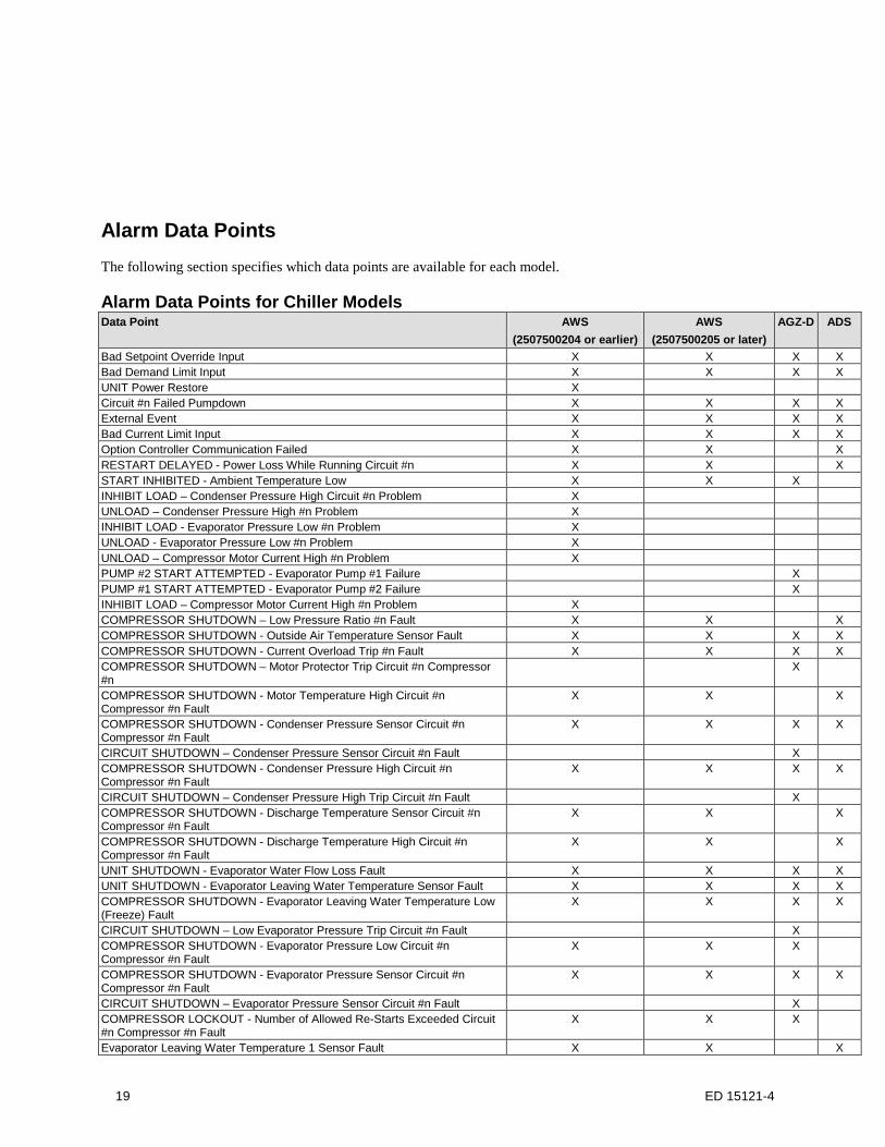
Alarm Data Points The following section specifies which data points are available for each model.
Alarm Data Points for Chiller Models Data Point AWS
(2507500204 or earlier) AWS
(2507500205 or later) AGZ-D ADS
Bad Setpoint Override Input X X X X Bad Demand Limit Input X X X X UNIT Power Restore X Circuit #n Failed Pumpdown X X X X External Event X X X X Bad Current Limit Input X X X X Option Controller Communication Failed X X X RESTART DELAYED - Power Loss While Running Circuit #n X X X START INHIBITED - Ambient Temperature Low X X X INHIBIT LOAD – Condenser Pressure High Circuit #n Problem X UNLOAD – Condenser Pressure High #n Problem X INHIBIT LOAD - Evaporator Pressure Low #n Problem X UNLOAD - Evaporator Pressure Low #n Problem X UNLOAD – Compressor Motor Current High #n Problem X PUMP #2 START ATTEMPTED - Evaporator Pump #1 Failure X PUMP #1 START ATTEMPTED - Evaporator Pump #2 Failure X INHIBIT LOAD – Compressor Motor Current High #n Problem X COMPRESSOR SHUTDOWN – Low Pressure Ratio #n Fault X X X COMPRESSOR SHUTDOWN - Outside Air Temperature Sensor Fault X X X X COMPRESSOR SHUTDOWN - Current Overload Trip #n Fault X X X X COMPRESSOR SHUTDOWN – Motor Protector Trip Circuit #n Compressor #n
X
COMPRESSOR SHUTDOWN - Motor Temperature High Circuit #n Compressor #n Fault
X X X
COMPRESSOR SHUTDOWN - Condenser Pressure Sensor Circuit #n Compressor #n Fault
X X X X
CIRCUIT SHUTDOWN – Condenser Pressure Sensor Circuit #n Fault X COMPRESSOR SHUTDOWN - Condenser Pressure High Circuit #n Compressor #n Fault
X X X X
CIRCUIT SHUTDOWN – Condenser Pressure High Trip Circuit #n Fault X COMPRESSOR SHUTDOWN - Discharge Temperature Sensor Circuit #n Compressor #n Fault
X X X
COMPRESSOR SHUTDOWN - Discharge Temperature High Circuit #n Compressor #n Fault
X X X
UNIT SHUTDOWN - Evaporator Water Flow Loss Fault X X X X UNIT SHUTDOWN - Evaporator Leaving Water Temperature Sensor Fault X X X X COMPRESSOR SHUTDOWN - Evaporator Leaving Water Temperature Low (Freeze) Fault
X X X X
CIRCUIT SHUTDOWN – Low Evaporator Pressure Trip Circuit #n Fault X COMPRESSOR SHUTDOWN - Evaporator Pressure Low Circuit #n Compressor #n Fault
X X X
COMPRESSOR SHUTDOWN - Evaporator Pressure Sensor Circuit #n Compressor #n Fault
X X X X
CIRCUIT SHUTDOWN – Evaporator Pressure Sensor Circuit #n Fault X COMPRESSOR LOCKOUT - Number of Allowed Re-Starts Exceeded Circuit #n Compressor #n Fault
X X X
Evaporator Leaving Water Temperature 1 Sensor Fault X X X
19 ED 15121-4

Data Point AWS (2507500204 or earlier)
AWS (2507500205 or later)
AGZ-D ADS
Evaporator Leaving Water Temperature 2 Sensor Fault X X X CIRCUIT SHUTDOWN- Evaporator 1 Freeze Protection Fault X X CIRCUIT SHUTDOWN- Evaporator 2 Freeze Protection Fault X X COMPRESSOR SHUTDOWN - Mechanical High Pressure Trip Circuit #n Compressor #n Fault
X X X
COMPRESSOR SHUTDOWN - Oil Delta Pressure High Circuit #n Compressor #n Fault
X X X
COMPRESSOR SHUTDOWN - Oil Feed Pressure Sensor Circuit #n Compressor #n Fault
X X X
SHUTDOWN – Phase Voltage Protection Fault X X X COMPRESSOR SHUTDOWN – Starter Fault Compressor #n Fault X X X COMPRESSOR SHUTDOWN - Suction Temperature Sensor Circuit #n Compressor #n Fault
X X X X
COMPRESSOR SHUTDOWN - No Pressure Change After Start Circuit #n X X X X COMPRESSOR SHUTDOWN - Mechanical Low Pressure Trip Circuit #n Compressor #n
X X
Controller Board #n Offline Fault X X X COMPRESSOR SHUTDOWN – Motor Temp Sensor Circuit #n Compressor #n
X X X
Alarm/Limit Controller Communication Failed X X X COMPRESSOR SHUTDOWN - No Pressure at Startup Circuit #n X X X UNIT SHUTDOWN - Evaporator Entering Water Temperature Sensor Fault X X X COMPRESSOR SHUTDOWN – Slide Position Sensor #n Fault X X X COMPRESSOR SHUTDOWN - COMPRESSOR VFD Fault Circuit #n Comp #n
X X X
COMPRESSOR SHUTDOWN - COMPRESSOR VFD Over Heat #n Fault X X X COMPRESSOR SHUTDOWN - COM ERROR with COMPRESSOR VFD Circuit #n Comp #n
X X X
UNIT STOP - Emergency Stop Alarm X X X UNIT STOP - Evaporator Water Temperatures Inverted X X X UNIT STOP – External Alarm X X X X COMPRESSOR SHUTDOWN – Low Discharge Superheat Circuit #n Compressor #n Fault
X X X
UNIT STOP - PVM GFP Fault X CIRCUIT SHUTDOWN- PVM GFP Circuit #n Fault X COMP SHUTDOWN- Refrig Charge Circuit #n Fault X Low Refrigerant Charge – Circuit #n Warning X
The following section describes the alarm data points supported by the MicroTech III Chiller Unit Controller. The unit controller contains one holding register for every possible alarm. These holding registers are read only and can be used to determine if any particular alarm is active or not. These points are not described in the Detailed Data Point Information section. The alarms are defined as Warning, Problem, and Fault (see Alarms section for more details). Tables 9-11 display the holding register for each alarm.
Table 9. Warning Alarms
Holding Register (4xxxx)
Warning Alarms Description
377 Bad setpoint override input 0=Normal, 1=Alarm 378 Bad demand limit input 0=Normal, 1=Alarm 7401 Unit power restore 0=Normal, 1=Alarm 741 Circuit #1 failed pumpdown 0=Normal, 1=Alarm 742 Circuit #2 failed pumpdown 0=Normal, 1=Alarm 743 Circuit #3 failed pumpdown 0=Normal, 1=Alarm 744 Circuit #4 failed pumpdown 0=Normal, 1=Alarm 745 External event 0=Normal, 1=Alarm 814 Bad Current Limit Input 0=Normal, 1=Alarm 815 Option Controller Communication Failed 0=Normal, 1=Alarm 825 Circuit #1 Low Refrigerant Charge 0=Normal, 1=Alarm 826 Circuit #2 Low Refrigerant Charge 0=Normal, 1=Alarm 827 Circuit #3 Low Refrigerant Charge 0=Normal, 1=Alarm 828 Chiller Network Communication Failure 0=Normal, 1=Alarm
20 ED 15121-4

1 This holding register is only valid on AWS versions 2507500204 or earlier. On older revisions of AWS, this register will always read zero.
Table 10. Problem Alarms
Holding Register (4xxxx)
Problem Alarms Description
384 RESTART DELAYED - Power Loss While Running Circuit #1 0=Normal, 1=Alarm 385 RESTART DELAYED - Power Loss While Running Circuit #2 0=Normal, 1=Alarm 386 RESTART DELAYED - Power Loss While Running Circuit #3 0=Normal, 1=Alarm 387 RESTART DELAYED - Power Loss While Running Circuit #4 0=Normal, 1=Alarm 388 START INHIBITED - Ambient Temperature Low 0=Normal, 1=Alarm 3901 INHIBIT LOAD – Condenser Pressure High Circuit #1 0=Normal, 1=Alarm 3911 INHIBIT LOAD – Condenser Pressure High Circuit #2 0=Normal, 1=Alarm 3921 INHIBIT LOAD – Condenser Pressure High Circuit #3 0=Normal, 1=Alarm 3931 INHIBIT LOAD – Condenser Pressure High Circuit #4 0=Normal, 1=Alarm 3951 UNLOAD – Condenser Pressure High Circuit #1 0=Normal, 1=Alarm 3961 UNLOAD – Condenser Pressure High Circuit #2 0=Normal, 1=Alarm 3971 UNLOAD – Condenser Pressure High Circuit #3 0=Normal, 1=Alarm 3981 UNLOAD – Condenser Pressure High Circuit #4 0=Normal, 1=Alarm 4111 INHIBIT LOAD - Evaporator Pressure Low Circuit #1 0=Normal, 1=Alarm 4121 INHIBIT LOAD - Evaporator Pressure Low Circuit #2 0=Normal, 1=Alarm 4131 INHIBIT LOAD - Evaporator Pressure Low Circuit #3 0=Normal, 1=Alarm 4141 INHIBIT LOAD - Evaporator Pressure Low Circuit #4 0=Normal, 1=Alarm 4161 UNLOAD - Evaporator Pressure Low Circuit #1 0=Normal, 1=Alarm 4171 UNLOAD - Evaporator Pressure Low Circuit #2 0=Normal, 1=Alarm 4181 UNLOAD - Evaporator Pressure Low Circuit #3 0=Normal, 1=Alarm 4191 UNLOAD - Evaporator Pressure Low Circuit #4 0=Normal, 1=Alarm 4201 UNLOAD - Compressor Motor Current High Circuit #1, Compressor #1 0=Normal, 1=Alarm 4221 UNLOAD - Compressor Motor Current High Circuit #2, Compressor #1 0=Normal, 1=Alarm 4241 UNLOAD - Compressor Motor Current High Circuit #3, Compressor #1 0=Normal, 1=Alarm 430 PUMP #2 START ATTEMPTED - Evaporator Pump #1 Failure 0=Normal, 1=Alarm 431 PUMP #1 START ATTEMPTED - Evaporator Pump #2 Failure 0=Normal, 1=Alarm 7801 INHIBIT LOAD - Compressor Motor Current High Circuit #1, Compressor #1 0=Normal, 1=Alarm 7821 INHIBIT LOAD - Compressor Motor Current High Circuit #2, Compressor #1 0=Normal, 1=Alarm 7841 INHIBIT LOAD - Compressor Motor Current High Circuit #3, Compressor #1 0=Normal, 1=Alarm
1 These holding registers are only valid on AWS versions 2507500204 or earlier. On older revisions of AWS, this register will always read zero.
Table 11. Fault Alarms
Holding Register (4xxxx)
Fault Alarms Description
440 COMPRESSOR SHUTDOWN - Low pressure ratio Circuit #1, Comp #1 0=Normal, 1=Alarm 442 COMPRESSOR SHUTDOWN - Low pressure ratio Circuit #2, Comp #1 0=Normal, 1=Alarm 444 COMPRESSOR SHUTDOWN - Low pressure ratio Circuit #3, Comp #1 0=Normal, 1=Alarm 445 COMPRESSOR SHUTDOWN - Low pressure ratio Circuit #4, Comp #1 0=Normal, 1=Alarm 446 UNIT SHUTDOWN - Outside Air Temperature Sensor Fault 0=Normal, 1=Alarm 447 COMPRESSOR SHUTDOWN - Current Overload Trip Circuit #1, Comp #1 0=Normal, 1=Alarm 449 COMPRESSOR SHUTDOWN - Current Overload Trip Circuit #2, Comp #1 0=Normal, 1=Alarm 451 COMPRESSOR SHUTDOWN - Current Overload Trip Circuit #3, Comp #1 0=Normal, 1=Alarm 466 COMP SHUTDOWN– Motor Protector Trip Circuit #1 Comp #1 0=Normal, 1=Alarm 468 COMP SHUTDOWN– Motor Protector Trip Circuit #2 Comp #1 0=Normal, 1=Alarm 478 COMPRESSOR SHUTDOWN - Motor Temperature High Circuit #1, Comp #1 0=Normal, 1=Alarm 480 COMPRESSOR SHUTDOWN - Motor Temperature High Circuit #2, Comp #1 0=Normal, 1=Alarm 482 COMPRESSOR SHUTDOWN - Motor Temperature High Circuit #3, Comp #1 0=Normal, 1=Alarm 483 COMPRESSOR SHUTDOWN - Motor Temperature High Circuit #4, Comp #1 0=Normal, 1=Alarm 509 COMPRESSOR SHUTDOWN - Condenser Pressure Sensor Fault Circuit #1, Comp #1 0=Normal, 1=Alarm 509 CIRCUIT SHUTDOWN – Condenser Pressure Sensor Circuit #1 Fault 0=Normal, 1=Alarm 511 CIRCUIT SHUTDOWN – Condenser Pressure Sensor Circuit #2 Fault 0=Normal, 1=Alarm 511 COMPRESSOR SHUTDOWN - Condenser Pressure Sensor Fault Circuit #2, Comp #1 0=Normal, 1=Alarm 513 COMPRESSOR SHUTDOWN - Condenser Pressure Sensor Fault Circuit #3, Comp #1 0=Normal, 1=Alarm 514 COMPRESSOR SHUTDOWN - Condenser Pressure Sensor Fault Circuit #4, Comp #1 0=Normal, 1=Alarm 517 COMPRESSOR SHUTDOWN - Condenser Pressure High Circuit #1, Comp #1 0=Normal, 1=Alarm 517 CIRCUIT SHUTDOWN – Condenser Pressure High Trip Circuit #1 Fault 0=Normal, 1=Alarm 519 COMPRESSOR SHUTDOWN - Condenser Pressure High Circuit #2, Comp #1 0=Normal, 1=Alarm 519 CIRCUIT SHUTDOWN – Condenser Pressure High Trip Circuit #2 Fault 0=Normal, 1=Alarm 521 COMPRESSOR SHUTDOWN - Condenser Pressure High Circuit #3, Comp #1 0=Normal, 1=Alarm 522 COMPRESSOR SHUTDOWN - Condenser Pressure High Circuit #4, Comp #1 0=Normal, 1=Alarm 529 COMPRESSOR SHUTDOWN - Discharge Temperature Sensor Fault Circuit #1, Comp #1 0=Normal, 1=Alarm
21 ED 15121-4

Holding Register (4xxxx)
Fault Alarms Description
531 COMPRESSOR SHUTDOWN - Discharge Temperature Sensor Fault Circuit #2, Comp #1 0=Normal, 1=Alarm 533 COMPRESSOR SHUTDOWN - Discharge Temperature Sensor Fault Circuit #3, Comp #1 0=Normal, 1=Alarm 534 COMPRESSOR SHUTDOWN - Discharge Temperature Sensor Fault Circuit #4, Comp #1 0=Normal, 1=Alarm 535 COMPRESSOR SHUTDOWN - Discharge Temperature High Circuit #1, Comp #1 0=Normal, 1=Alarm 537 COMPRESSOR SHUTDOWN - Discharge Temperature High Circuit #2, Comp #1 0=Normal, 1=Alarm 539 COMPRESSOR SHUTDOWN - Discharge Temperature High Circuit #3, Comp #1 0=Normal, 1=Alarm 540 COMPRESSOR SHUTDOWN - Discharge Temperature High Circuit #4, Comp #1 0=Normal, 1=Alarm 542 UNIT SHUTDOWN - Evaporator Water Flow Loss 0=Normal, 1=Alarm 543 UNIT SHUTDOWN - Evaporator Leaving Water Temperature Low (Freeze) 0=Normal, 1=Alarm 545 COMPRESSOR SHUTDOWN - Evaporator Pressure Low Circuit #1, Comp #1 0=Normal, 1=Alarm 545 CIRCUIT SHUTDOWN – Low Evaporator Pressure Trip Circuit #1 Fault 0=Normal, 1=Alarm 547 COMPRESSOR SHUTDOWN - Evaporator Pressure Low Circuit #2, Comp #1 0=Normal, 1=Alarm 547 CIRCUIT SHUTDOWN – Low Evaporator Pressure Trip Circuit #2 Fault 0=Normal, 1=Alarm 549 COMPRESSOR SHUTDOWN - Evaporator Pressure Low Circuit #3, Comp #1 0=Normal, 1=Alarm 550 COMPRESSOR SHUTDOWN - Evaporator Pressure Low Circuit #4, Comp #1 0=Normal, 1=Alarm 552 COMPRESSOR SHUTDOWN - Evaporator Pressure Sensor Fault Circuit #1 Comp #1 0=Normal, 1=Alarm 552 CIRCUIT SHUTDOWN – Evaporator Pressure Sensor Circuit #1 Fault 0=Normal, 1=Alarm 554 COMPRESSOR SHUTDOWN - Evaporator Pressure Sensor Fault Circuit #2 Comp #1 0=Normal, 1=Alarm 554 CIRCUIT SHUTDOWN – Evaporator Pressure Sensor Circuit #2 Fault 0=Normal, 1=Alarm 556 COMPRESSOR SHUTDOWN - Evaporator Pressure Sensor Fault Circuit #3 Comp #1 0=Normal, 1=Alarm 557 COMPRESSOR SHUTDOWN - Evaporator Pressure Sensor Fault Circuit #4 Comp #1 0=Normal, 1=Alarm 583 COMPRESSOR LOCKOUT - Number of Allowed Re-Starts Exceeded Circuit #1, Comp#1 0=Normal, 1=Alarm 585 COMPRESSOR LOCKOUT - Number of Allowed Re-Starts Exceeded Circuit #2, Comp#1 0=Normal, 1=Alarm 587 COMPRESSOR LOCKOUT - Number of Allowed Re-Starts Exceeded Circuit #3, Comp#1 0=Normal, 1=Alarm 588 COMPRESSOR LOCKOUT - Number of Allowed Re-Starts Exceeded Circuit #4, Comp#1 0=Normal, 1=Alarm 589 UNIT SHUTDOWN - Evaporator Leaving Water Temperature Sensor Fault 0=Normal, 1=Alarm 590 Evaporator Leaving Water Temperature 1 Sensor Fault 0=Normal, 1=Alarm 591 Evaporator Leaving Water Temperature 2 Sensor Fault 0=Normal, 1=Alarm 592 CIRCUIT SHUTDOWN - Evaporator 1 Freeze Protection 0=Normal, 1=Alarm 593 CIRCUIT SHUTDOWN - Evaporator 2 Freeze Protection 0=Normal, 1=Alarm 601 COMPRESSOR SHUTDOWN - Mechanical High Pressure Trip Circuit #1, Comp #1 0=Normal, 1=Alarm 603 COMPRESSOR SHUTDOWN - Mechanical High Pressure Trip Circuit #2, Comp #1 0=Normal, 1=Alarm 605 COMPRESSOR SHUTDOWN - Mechanical High Pressure Trip Circuit #3, Comp #1 0=Normal, 1=Alarm 606 COMPRESSOR SHUTDOWN - Mechanical High Pressure Trip Circuit #4, Comp #1 0=Normal, 1=Alarm 637 COMPRESSOR SHUTDOWN - Oil Delta Pressure High Circuit #1, Comp #1 0=Normal, 1=Alarm 639 COMPRESSOR SHUTDOWN - Oil Delta Pressure High Circuit #2, Comp #1 0=Normal, 1=Alarm 641 COMPRESSOR SHUTDOWN - Oil Delta Pressure High Circuit #3, Comp #1 0=Normal, 1=Alarm 642 COMPRESSOR SHUTDOWN - Oil Delta Pressure High Circuit #4, Comp #1 0=Normal, 1=Alarm 643 COMPRESSOR SHUTDOWN - Oil Feed Pressure Sensor Fault Circuit #1, Comp #1 0=Normal, 1=Alarm 645 COMPRESSOR SHUTDOWN - Oil Feed Pressure Sensor Fault Circuit #2, Comp #1 0=Normal, 1=Alarm 647 COMPRESSOR SHUTDOWN - Oil Feed Pressure Sensor Fault Circuit #3, Comp #1 0=Normal, 1=Alarm 648 COMPRESSOR SHUTDOWN - Oil Feed Pressure Sensor Fault Circuit #4, Comp #1 0=Normal, 1=Alarm 661 SHUTDOWN – Phase Voltage Protection 0=Normal, 1=Alarm 662 COMPRESSOR SHUTDOWN - Starter Fault Compressor Circuit #1, Comp #1 0=Normal, 1=Alarm 664 COMPRESSOR SHUTDOWN - Starter Fault Compressor Circuit #2, Comp #1 0=Normal, 1=Alarm 666 COMPRESSOR SHUTDOWN - Starter Fault Compressor Circuit #3, Comp #1 0=Normal, 1=Alarm 667 COMPRESSOR SHUTDOWN - Starter Fault Compressor Circuit #4, Comp #1 0=Normal, 1=Alarm 698 COMPRESSOR SHUTDOWN - Suction Temperature Sensor Fault Circuit #1, Comp #1 0=Normal, 1=Alarm 700 COMPRESSOR SHUTDOWN - Suction Temperature Sensor Fault Circuit #2, Comp #1 0=Normal, 1=Alarm 702 COMPRESSOR SHUTDOWN - Suction Temperature Sensor Fault Circuit #3, Comp #1 0=Normal, 1=Alarm 703 COMPRESSOR SHUTDOWN - Suction Temperature Sensor Fault Circuit #4, Comp #1 0=Normal, 1=Alarm 711 COMPRESSOR SHUTDOWN – No Pressure at Startup Circuit #1 0=Normal, 1=Alarm 712 COMPRESSOR SHUTDOWN – No Pressure at Startup Circuit #2 0=Normal, 1=Alarm 713 COMPRESSOR SHUTDOWN – No Pressure at Startup Circuit #3 0=Normal, 1=Alarm 714 COMPRESSOR SHUTDOWN – No Pressure at Startup Circuit #4 0=Normal, 1=Alarm 717 COMPRESSOR SHUTDOWN - Mechanical Low Pressure Trip Circuit #1, Comp #1 0=Normal, 1=Alarm 719 COMPRESSOR SHUTDOWN - Mechanical Low Pressure Trip Circuit #2, Comp #1 0=Normal, 1=Alarm 721 COMPRESSOR SHUTDOWN - Mechanical Low Pressure Trip Circuit #3, Comp #1 0=Normal, 1=Alarm 722 COMPRESSOR SHUTDOWN - Mechanical Low Pressure Trip Circuit #4, Comp #1 0=Normal, 1=Alarm 723 Controller board offline Circuit #1 (Circuit number describes Control board number) 0=Normal, 1=Alarm 724 Controller board offline Circuit #2 (Circuit number describes Control board number) 0=Normal, 1=Alarm 725 Controller board offline Circuit #3 (Circuit number describes Control board number) 0=Normal, 1=Alarm 726 Controller board offline Circuit #4 (Circuit number describes Control board number) 0=Normal, 1=Alarm 734 Compressor Shutdown - Motor Temperature Sensor Fault Circuit #1, Comp #1 0=Normal, 1=Alarm 736 Compressor Shutdown - Motor Temperature Sensor Fault Circuit #2, Comp #1 0=Normal, 1=Alarm 738 Compressor Shutdown - Motor Temperature Sensor Fault Circuit #3, Comp #1 0=Normal, 1=Alarm 739 Compressor Shutdown - Motor Temperature Sensor Fault Circuit #4, Comp #1 0=Normal, 1=Alarm 746 Controller board offline Alm/Limit Ext Module 0=Normal, 1=Alarm
22 ED 15121-4

Holding Register (4xxxx)
Fault Alarms Description
747 COMPRESSOR SHUTDOWN – No Pressure Change After Start Circuit #1 0=Normal, 1=Alarm 748 COMPRESSOR SHUTDOWN - No Pressure Change After Start Circuit #2 0=Normal, 1=Alarm 749 COMPRESSOR SHUTDOWN - No Pressure Change After Start Circuit #3 0=Normal, 1=Alarm 750 COMPRESSOR SHUTDOWN - No Pressure Change After Start Circuit #4 0=Normal, 1=Alarm 751 SHUTDOWN – Phase Voltage Protection Circuit #1 0=Normal, 1=Alarm 752 SHUTDOWN – Phase Voltage Protection Circuit #2 0=Normal, 1=Alarm 753 SHUTDOWN – Phase Voltage Protection Circuit #3 0=Normal, 1=Alarm 754 SHUTDOWN – Phase Voltage Protection Circuit #4 0=Normal, 1=Alarm 755 UNIT SHUTDOWN - Evaporator Entering Water Temperature Sensor Fault 0=Normal, 1=Alarm 756 COMPRESSOR SHUTDOWN - Slide position sensor fault Circuit #1, Comp#1 0=Normal, 1=Alarm 758 COMPRESSOR SHUTDOWN - Slide position sensor fault Circuit #2, Comp#1 0=Normal, 1=Alarm 760 COMPRESSOR SHUTDOWN - Slide position sensor fault Circuit #3, Comp#1 0=Normal, 1=Alarm 761 COMPRESSOR SHUTDOWN - Slide position sensor fault Circuit #4, Comp#1 0=Normal, 1=Alarm 762 COMPRESSOR SHUTDOWN - COMPRESSOR VFD Fault Circuit #1, Comp #1 0=Normal, 1=Alarm 764 COMPRESSOR SHUTDOWN - COMPRESSOR VFD Fault Circuit #2, Comp #1 0=Normal, 1=Alarm 766 COMPRESSOR SHUTDOWN - COMPRESSOR VFD Fault Circuit #3, Comp #1 0=Normal, 1=Alarm 768 COMPRESSOR SHUTDOWN - COMPRESSOR VFD Over Heat Fault Circuit #1, Comp #1 0=Normal, 1=Alarm 770 COMPRESSOR SHUTDOWN - COMPRESSOR VFD Over Heat Fault Circuit #2, Comp #1 0=Normal, 1=Alarm 772 COMPRESSOR SHUTDOWN - COMPRESSOR VFD Over Heat Fault Circuit #3, Comp #1 0=Normal, 1=Alarm 774 COMPRESSOR SHUTDOWN - COM ERROR With COMPRESSOR VFD Circuit #1, Comp #1 0=Normal, 1=Alarm 776 COMPRESSOR SHUTDOWN - COM ERROR With COMPRESSOR VFD Circuit #2, Comp #1 0=Normal, 1=Alarm 778 COMPRESSOR SHUTDOWN - COM ERROR With COMPRESSOR VFD Circuit #3, Comp #1 0=Normal, 1=Alarm 798 UNIT STOP - Emergency Stop Alarm 0=Normal, 1=Alarm 799 UNIT STOP - Evaporator Water Temperatures Inverted 0=Normal, 1=Alarm 800 UNIT STOP - External Alarm 0=Normal, 1=Alarm 808 COMP SHUTDOWN-Low Discharge Superheat Circuit #1, Comp #1 0=Normal, 1=Alarm 810 COMP SHUTDOWN-Low Discharge Superheat Circuit #2, Comp #1 0=Normal, 1=Alarm 812 COMP SHUTDOWN-Low Discharge Superheat Circuit #3, Comp #1 0=Normal, 1=Alarm 816 UNIT STOP - PVM GFP Fault 0=Normal, 1=Alarm 817 CIRCUIT SHUTDOWN- PVM GFP Circuit 1 Fault 0=Normal, 1=Alarm 818 CIRCUIT SHUTDOWN- PVM GFP Circuit 2 Fault 0=Normal, 1=Alarm 822 COMP SHUTDOWN-Refrig Charge Circuit #1 0=Normal, 1=Alarm 823 COMP SHUTDOWN-Refrig Charge Circuit #2 0=Normal, 1=Alarm 824 COMP SHUTDOWN-Refrig Charge Circuit #3 0=Normal, 1=Alarm
23 ED 15121-4
Detailed Data Point Information The following section details the information (the data) available to the Building Automation System (BAS) via the Modbus RTU protocol.
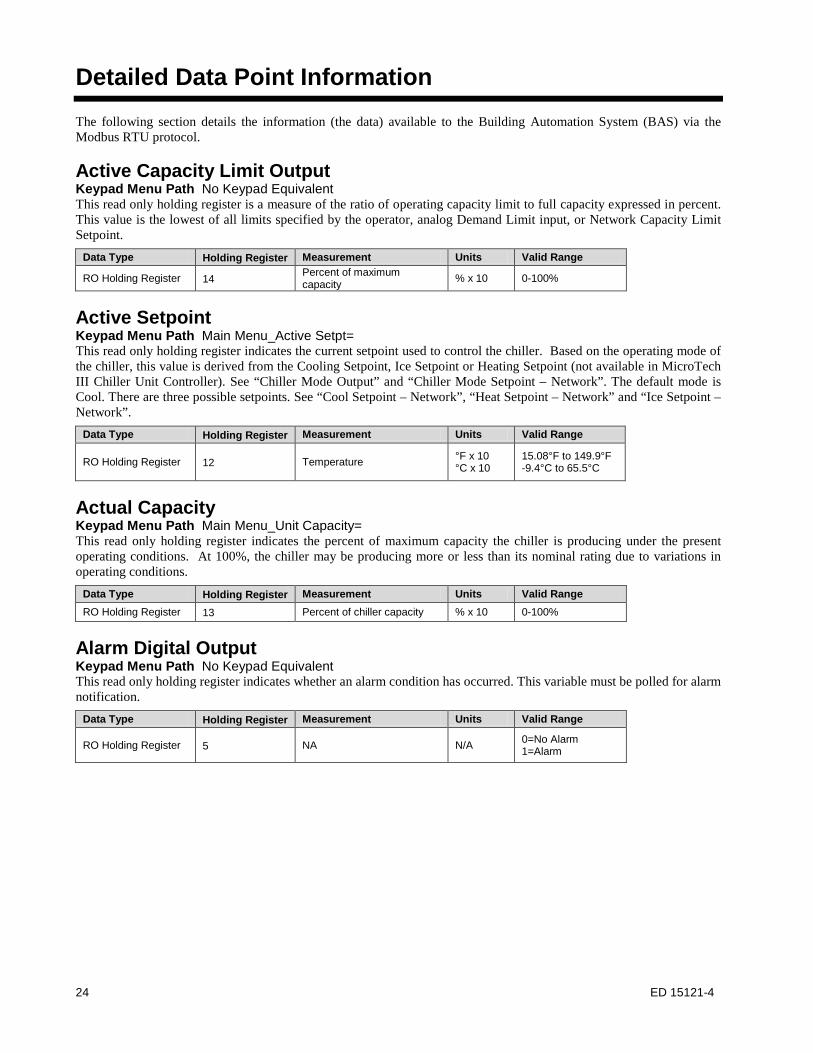
Active Capacity Limit Output Keypad Menu Path No Keypad Equivalent This read only holding register is a measure of the ratio of operating capacity limit to full capacity expressed in percent. This value is the lowest of all limits specified by the operator, analog Demand Limit input, or Network Capacity Limit Setpoint.
Data Type Holding Register Measurement Units Valid Range
RO Holding Register 14 Percent of maximum capacity % x 10 0-100%
Active Setpoint Keypad Menu Path Main Menu_Active Setpt= This read only holding register indicates the current setpoint used to control the chiller. Based on the operating mode of the chiller, this value is derived from the Cooling Setpoint, Ice Setpoint or Heating Setpoint (not available in MicroTech III Chiller Unit Controller). See “Chiller Mode Output” and “Chiller Mode Setpoint – Network”. The default mode is Cool. There are three possible setpoints. See “Cool Setpoint – Network”, “Heat Setpoint – Network” and “Ice Setpoint – Network”.
Data Type Holding Register Measurement Units Valid Range
RO Holding Register 12 Temperature °F x 10 °C x 10
15.08°F to 149.9°F -9.4°C to 65.5°C
Actual Capacity Keypad Menu Path Main Menu_Unit Capacity= This read only holding register indicates the percent of maximum capacity the chiller is producing under the present operating conditions. At 100%, the chiller may be producing more or less than its nominal rating due to variations in operating conditions.
Data Type Holding Register Measurement Units Valid Range RO Holding Register 13 Percent of chiller capacity % x 10 0-100%
Alarm Digital Output Keypad Menu Path No Keypad Equivalent This read only holding register indicates whether an alarm condition has occurred. This variable must be polled for alarm notification.
Data Type Holding Register Measurement Units Valid Range
RO Holding Register 5 NA N/A 0=No Alarm 1=Alarm
24 ED 15121-4

Application Software Version Keypad Menu Path Main Menu_About Chiller_Unit S/N= These read only holding registers indicate the software version of the application software. The following example shows the holding register and its value (in hexadecimal), followed by the ASCII character translation. • 334= 0x3235
• 0x32 = “2”• 0x35 = “5”
• 335= 0x3035• 0x30 = “0”• 0x35 = “5”
• 335= 0x3036• 0x30 = “0” Application Version = 2505067100 • 0x35 = “6”
• 337= 0x3731• 0x37 = “7”• 0x31 = “1”
• 338= 0x3030• 0x30 = “0”• 0x30 = “0”
Data Type Holding Register Measurement Units Valid Range RO Holding Register 334-338 NA N/A 1-10 Characters
Capacity Limit Setpoint - Network Keypad Menu Path Main Menu_View/Set Unit_Status/Settings_Netwrk Cap Lim= This read/write holding register sets the maximum capacity level of the chiller. This level may be adjusted via an operator workstation or other network device, but cannot be adjusted above a factory-specified limit. The default is 100%. This register is ignored by the chiller application if Chiller Local/Remote is set to Local.
Data Type Holding Register Measurement Units Valid Range
RW Holding Register 38 Percent of maximum capacity % x 10 0-100%
Chiller Capacity Limited Keypad Menu Path No Keypad Equivalent This read only holding register indicates whether conditions may exist that prevent the chiller from reaching full capacity. If conditions exist that limit operation, the chiller may be prevented from reaching the Leaving Water Temperature setpoint.
Data Type Holding Register Measurement Units Valid Range
RO Holding Register 4 Status N/A 0=Not Limited 1=Limited
Chiller Current Keypad Menu Path Main Menu_View/Set Unit_Power Conservation_Unit Current= This read only holding register indicates the average current of the chiller. Compressor currents may be added together to calculate this value.
Data Type Holding Register Measurement Units Valid Range RO Holding Register 25 Electric Current Amperes 0-10,000
25 ED 15121-4

Chiller Enable Output Keypad Menu Path Main Menu_View/Set Unit_Status/Settings_Netwrk En SP= This read only holding register indicates if operation of the chiller is disabled or enabled. If the chiller is disabled, it cannot run. If it is enabled, it is allowed to run.
Data Type Holding Register Measurement Units Valid Range
RO Holding Register 2 Chiller state N/A 0=Disable 1=Enable
Chiller Enable Setpoint Keypad Menu Path No Keypad Equivalent This read/write holding register is used enable the chiller to run if operating conditions are satisfied, or disables the chiller from running. The default is Null which will cause Disable to be used provided nothing else is writing to this point. This register is ignored by the chiller application if Chiller Local/Remote is set to Local.
Data Type Holding Register Measurement Units Valid Range
RW Holding Register 9 Chiller State N/A 0=Disable 1=Enable 2=Null
Chiller Local/Remote Keypad Menu Path No Keypad Equivalent This read only holding register indicates whether the chiller is in local control or allowed to be controlled remotely over the network. The value can only be changed locally. The values from the following variables are ignored in the chiller application if this variable is set to Local (1): • Chiller Enable Setpoint• Chiller Mode Setpoint – Network• Cool Setpoint Network• Ice Setpoint Network• Capacity Limit Setpoint• Clear Alarm Network
Data Type Holding Register Measurement Units Valid Range
RO Holding Register 1 Mode N/A 0=Remote 1=Local
Chiller Location Keypad Menu Path No Keypad Equivalent These read/write holding registers provides a description of the location. If the location is changed via Modbus, the change is written immediately to the unit controller. However, if the location is changed by an outside source (other than Modbus), then change will not be available via Modbus until power is cycled.
Data Type Holding Register Measurement Units Valid Range
RW Holding Register 318-327 Location N/A
ASCII String up to 20 characters. The string cannot contain “ or $ characters.
Chiller Mode Output Keypad Menu Path Main Menu_View/Set Unit_Status/Settings_Netwrk Mode SP= This read only holding register indicates the current operating mode of the chiller.
Data Type Holding Register Measurement Units Valid Range
RO Holding Register 11 HVAC mode N/A
1=Ice 2=Cool 3=Heat 4=Cool/Heat Recovery 5=Defrost
26 ED 15121-4

Chiller Mode Setpoint - Network Keypad Menu Path No Keypad Equivalent This read/write holding register is used to change the operating mode of the chiller. The default is Null(0). A value of Null will cause the chiller to run in the Cool mode provided that nothing else is writing to this point. This register is ignored by the chiller application if Chiller Local/Remote is set to Local. It also only applies when Available Modes is set to Cool/Ice w/Glycol. Available Modes can also be found on the keypad. Only Ice and Cool modes are supported. If any other mode is written, the chiller will be set to Cool mode.
Data Type Holding Register Measurement Units Valid Range
RW Holding Register 34 HVAC Mode N/A
0=Null 1=Ice 2=Cool 3=Heat 4=Cool/Heat Recovery
Chiller Model Keypad Menu Path No Keypad Equivalent This read only holding register indicates the model of the chiller.
Data Type Holding Register Measurement Units Valid Range
RO Holding Register 317 Chiller Model N/A
0=Centrifugal, 1=Water Cooled, 2=Air Cooled, 3=HeatPump, 9=Other
Chiller On/Off Keypad Menu Path No Keypad Equivalent This read only holding register indicates the current state of the chiller. The OFF state is represented by state = FALSE and value = 0. The other discrete states are represented by state = TRUE and value > 0.
Data Type Holding Register Measurement Units Valid Range
RO Holding Register 8 Chiller State N/A 0=Off 1=On
Chiller Status Keypad Menu Path No Keypad Equivalent This read only holding register indicates the unit status of the chiller.
Data Type Holding Register Measurement Units Valid Range
RO Holding Register 15 Chiller State N/A
1=Off 2=Start 3=Run 4=Pre Shutdown 5=Service
Clear Alarms - Network Keypad Menu Path No Keypad Equivalent This read/write input network variable clears all active alarms. Many alarms are automatically clearing alarms. Of the alarms that need to be manually cleared, the alarms listed below cannot be cleared from the network: • COMPRESSOR SHUTDOWN - Evaporator Pressure Low Circuit #n Compressor #n Fault• COMPRESSOR SHUTDOWN - Condenser Pressure High Circuit #n Compressor #n Fault• COMPRESSOR SHUTDOWN - Motor Temperature High Circuit #n Compressor #n Fault• UNIT SHUTDOWN – Evaporator Leaving Water Temp Low (Freeze)• COMPRESSOR SHUTDOWN - Mechanical High Pressure Trip Circuit #n Compressor #n Fault• COMPRESSOR SHUTDOWN - Mechanical Low Pressure Trip Circuit #n Compressor #n Fault
The default is Null, which will cause Normal to be used provided nothing else is writing to this point. This register is ignored by the chiller application if Chiller Local/Remote is set to Local.
Data Type Holding Register Measurement Units Valid Range
RW Holding Register 10 NA N/A 0=Normal 1=Clear Alarm 2=Null
27 ED 15121-4

Compressor Current Keypad Menu Path Main Menu_View/Set Circuit_Circuit #1_Comp 1_Current= OR Main Menu_View/Set Circuit_Circuit #2_Comp 1_Current= OR Main Menu_View/Set Circuit_Circuit #3_Comp 1_Current=
These read only holding registers indicate the average current of the compressor motor. For BACnet there is a separate variable for each compressor.
Data Type Holding Register Measurement Units Valid Range
RO Holding Register Cir#1Cmp#1=70 Cir#2Cmp#1=109 Cir#3Cmp#1=148
Electrical Current Amperes 0-10,000
Compressor Discharge Refrigerant Temperature Keypad Menu Path Main Menu_View/Set Circuit_Circuit #1_Data_Discharge Temp= OR Main Menu_View/Set Circuit_Circuit #2_Data_Discharge Temp= OR Main Menu_View/Set Circuit_Circuit #3_Data_Discharge Temp= OR Main Menu_View/Set Circuit_Circuit #4_Data_Discharge Temp=
These read only holding registers indicate the current refrigerant temperature discharged from the compressor. There is a separate holding register for each compressor.
Data Type Holding Register Measurement Units Valid Range
RO Holding Register
Cir#1Cmp#1=68 Cir#2Cmp#1=107 Cir#3Cmp#1=146 Cir#4Cmp#1=185
Temperature °F x 10 °C x 10
-40°– 250°F, -40°– 121°C
Compressor Percent RLA Keypad Menu Path Main Menu_View/Set Circuit_Circuit #1_Comp 1_Percent RLA= OR Main Menu_View/Set Circuit_Circuit #2_Comp 1_Percent RLA= OR Main Menu_View/Set Circuit_Circuit #3_Comp 1_Percent RLA=
These read only holding registers indicate the current percent RLA for the compressor motor of the compressor.
Data Type Holding Register Measurement Units Valid Range
RO Holding Register Cir#1Cmp#1=69 Cir#2Cmp#1=108 Cir#3Cmp#1=147
Percent RLA Percent 0-100%
Compressor Power Keypad Menu Path No Keypad Equivalent
These read only holding registers indicate the current power of the compressor motor. There is a separate variable for each compressor.
Data Type Holding Register Measurement Units Valid Range
RO Holding Register Cir#1Cmp#1=72 Cir#2Cmp#1=111 Cir#3Cmp#1=150
Electric Power kiloWatts 0-3500
28 ED 15121-4

Compressor Run Hours Keypad Menu Path Main Menu_View/Set Circuit_Circuit #1_Comp 1_Run Hours=OR Main Menu_View/Set Circuit_Circuit #1_Comp 2_Run Hours=OR Main Menu_View/Set Circuit_Circuit #1_Comp 3_Run Hours=OR Main Menu_View/Set Circuit_ Circuit #2_Comp 1_Run Hours= OR Main Menu_View/Set Circuit_ Circuit #2_Comp 2_Run Hours= OR Main Menu_View/Set Circuit_ Circuit #2_Comp 3_Run Hours= OR Main Menu_View/Set Circuit_ Circuit #3_Comp 1_Run Hours= OR Main Menu_View/Set Circuit_ Circuit #4_Comp 1_Run Hours=
These read/write holding registers indicate the number of hours that the compressor motor has been turned on. There is a separate holding register for each compressor.
Data Type Holding Register Measurement Units Valid Range
RW Holding Register
Cir#1Cmp#1=74-75 Cir#1Cmp#2=87-88 Cir#1Cmp#3=100-101 Cir#2Cmp#1=113-114 Cir#2Cmp#2=126-127 Cir#2Cmp#3=139-140 Cir#3Cmp#1=152-153 Cir#4Cmp#1=191-192
Time Hours 0-999,999
Compressor Starts Keypad Menu Path Main Menu_View/Set Circuit_ Circuit #1_Comp 1_No. Of Starts= OR Main Menu_View/Set Circuit_ Circuit #1_Comp 2_No. Of Starts= OR Main Menu_View/Set Circuit_ Circuit #1_Comp 3_No. Of Starts= OR Main Menu_View/Set Circuit_ Circuit #2_Comp 1_No. Of Starts= OR Main Menu_View/Set Circuit_ Circuit #2_Comp 2_No. Of Starts= OR Main Menu_View/Set Circuit_ Circuit #2_Comp 3_No. Of Starts= OR Main Menu_View/Set Circuit_ Circuit #3_Comp 1_No. Of Starts= OR Main Menu_View/Set Circuit_ Circuit #4_Comp 1_No. Of Starts=
These read only holding registers indicate the number of times the compressor motor has been started. There is a separate holding register for each compressor.
Data Type Holding Register Measurement Units Valid Range
RO Holding Register
Cir#1Cmp#1=73 Cir#1Cmp#2=86 Cir#1Cmp#3=99 Cir#2Cmp#1=112 Cir#2Cmp#2=125 Cir#2Cmp#3=138 Cir#3Cmp#1=151 Cir#4Cmp#1=190
Count Starts 0-65,535
Compressor Suction Refrigerant Temperature Keypad Menu Path Main Menu_View/Set Circuit_Circuit #1_Data_Suction Temp= OR Main Menu_View/Set Circuit_Circuit #2_Data_Suction Temp= OR Main Menu_View/Set Circuit_Circuit #3_Data_Suction Temp= OR Main Menu_View/Set Circuit_Circuit #4_Data_Suction Temp=
These read only holding registers indicate the current refrigerant temperature entering the compressor. There is a separate holding register for each compressor.
Data Type Holding Register Measurement Units Valid Range
RO Holding Register
Cir#1Cmp#1=65 Cir#2Cmp#1=104 Cir#3Cmp#1=143 Cir#4Cmp#1=182
Temperature °F x 10 °C x 10
-40-230° F -40-110° C
29 ED 15121-4

Compressor Voltage Keypad Menu Path No Keypad Equivalent
These read only holding registers indicate the average voltage of the compressor motor. There is a separate register for each compressor.
Data Type Holding Register Measurement Units Valid Range
RO Holding Register Cir#1Cmp#1=71 Cir#2Cmp#1=110 Cir#3Cmp#1=149
Electric Voltage VAC 0-15,000
Condenser Refrigerant Pressure Keypad Menu Path Main Menu_View/Set Circuit_Circuit #1_Data_Cond Pressure= OR Main Menu_View/Set Circuit_Circuit #2_Data_Cond Pressure = OR Main Menu_View/Set Circuit_Circuit #3_Data_Cond Pressure = OR Main Menu_View/Set Circuit_Circuit #4_Data_Cond Pressure =
These read only holding registers indicate the current condenser pressure. There is a separate holding register for each compressor.
Data Type Holding Register Measurement Units Valid Range
RO Holding Register
Circuit #1=39 Circuit #2=43 Circuit #3=47 Circuit #4=51
Pressure (gauge)
psi x 10 kPa x 10
0-410 psi (700 psi for R410A) 0-2827 kPa, (4826 kPa for R410A)
Condenser Saturated Refrigerant Temperature Keypad Menu Path Main Menu_View/Set Circuit_Circuit #1_Data_Cond Sat Temp= OR Main Menu_View/Set Circuit_Circuit #2_ Data_Cond Sat Temp = OR Main Menu_View/Set Circuit_Circuit #3_ Data_Cond Sat Temp = OR Main Menu_View/Set Circuit_Circuit #4_ Data_Cond Sat Temp =
These read only holding registers indicate the current saturated refrigerant temperature of the condenser. There is a separate holding register for each condenser.
Data Type Holding Register Measurement Units Valid Range
RO Holding Register
Circuit #1=40 Circuit #2=44 Circuit #3=48 Circuit #4=52
Temperature °F x 10 °C x 10
-14.98-185°F -26.1-85° C
Cool Setpoint - Network Keypad Menu Path Main Menu_View/Set Unit_Status/Settings_Netwrk Cool SP= This read/write holding register is used to change the Cooling setpoint from the network. It sets the temperature of the Leaving Chilled Fluid when the chiller is operating in the Cooling Mode. The default is 44°F. This register is ignored by the chiller application if Chiller Local/Remote is set to Local.
Data Type Holding Register Measurement Units Valid Range
RW Holding Register 35 Temperature °F x 10 °C x 10
24.98-60.08° F (-3.9-15.6° C) Default = 43.88° F (6.6°C)
30 ED 15121-4

Current Date & Time Keypad Menu Path (Chiller Date & Time) Main Menu_View/Set Unit_Date/TimeSchedules_Actual Time= AND Main Menu_View/Set Unit_Date/TimeSchedules_Actual Date=
These read/write holding registers are used to synchronize the chiller’s internal time clock with the BAS.
Data Type Holding Register Measurement Units Valid Range RW Holding Register 309 Integer Year
RW Holding Register 310 Integer Month 1-12
RW Holding Register 311 Integer Date 1-31
RO Holding Register 312 Integer Day of Week 0 (Monday) - 6 (Sunday)
RW Holding Register 313 Integer Hour 0-23
RW Holding Register 314 Integer Minute 0-59
RW Holding Register 315 Integer Second 0-59
Evaporator Entering Fluid Temperature Keypad Menu Path Main Menu_Evaporator EWT= This read only holding register indicates the temperature of the fluid entering the evaporator.
Data Type Holding Register Measurement Units Valid Range
RO Holding Register 16 Temperature °F x 10 °C x 10
-40-230° F -40-110° C
Evaporator Flow Switch Status Keypad Menu Path No Keypad Equivalent This read only output network indicates the status of the fluid flowing through the evaporator.
Data Type Holding Register Measurement Units Valid Range
RO Holding Register 6 Flow State N/A 0=No Flow 1=Flow
Evaporator Leaving Fluid Temperature Keypad Menu Path Main Menu_Evaporator LWT= This read only holding register indicates the current temperature of the fluid leaving the evaporator.
Data Type Holding Register Measurement Units Valid Range
RO Holding Register 17 Temperature °F x 10 °C x 10
-40-230° F -40-110° C
Evaporator Pump Run Hours Keypad Menu Path Main Menu_View/Set Unit_Status/Settings_Evap Pmp 1 Hrs= AND Main Menu_View/Set Unit_Status/Settings_Evap Pmp 2 Hrs= These read/write holding registers indicate the number of hours that the pump motor has been turned on. There is separate holding register for each pump. Pump #1 Data Type Holding Register Measurement Units Valid Range RW Holding Register 303-304 Time Hours 0-999,999
Pump #2 Data Type Holding Register Measurement Units Valid Range RW Holding Register 306-307 Time Hours 0-999,999
31 ED 15121-4

Evaporator Pump Status Keypad Menu Path No Keypad Equivalent These read only holding registers indicate if the pump has been commanded On or Off. There is a separate holding register for each pump. Pump #1 Data Type Holding Register Measurement Units Valid Range
RO Holding Register 305 Flow State N/A 0=Pump Off Request 1=Pump On Request
Pump #2 Data Type Holding Register Measurement Units Valid Range
RO Holding Register 308 Flow State N/A 0=Pump Off Request 1=Pump On Request
Evaporator Refrigerant Pressure Keypad Menu Path Main Menu_View/Set Circuit_Circuit #1_Data_Evap Pressure= AND Main Menu_View/Set/Circuit_Circuit #2_Data_Evap Pressure= AND Main Menu_View/Set/Circuit_Circuit #3_Data_Evap Pressure= AND Main Menu_View/Set/Circuit_Circuit #4_Data_Evap Pressure=
These read only holding registers indicate the current refrigerant pressure in the evaporator. There is a separate holding register for each compressor.
Data Type Holding Register Measurement Units Valid Range
RO Holding Register
Circuit #1=41 Circuit #2=45 Circuit #3=49 Circuit #4=53
Pressure (gauge)
psi x 10 kPa x 10
-349.97–349.97 psi -2413 kPa – 2413 kPa
Evaporator Saturated Refrigerant Temperature Keypad Menu Path Main Menu_View/Set Circuit_Circuit #1_Data_Evap Sat Temp= AND Main Menu_View/Set Circuit _Circuit #2_Data_Evap Sat Temp= AND Main Menu_View/Set Circuit _Circuit #3_Data_Evap Sat Temp= AND Main Menu_View/Set Circuit _Circuit #4_Data_Evap Sat Temp=
These read only holding registers indicate the current saturated refrigerant temperature of the evaporator. There is a separate holding register for each condenser.
Data Type Holding Register Measurement Units Valid Range
RO Holding Register
Circuit #1=42 Circuit #2=46 Circuit #3=50 Circuit #4=54
Temperature °F x 10 °C x 10
-14.98-185°F -26.1-85° C
Fault Alarm Code Keypad Menu Path No Keypad Equivalent This read only holding register allows individual notification of the active fault code. The alarms are not ordered based on any priority. If multiple fault alarms are present at one time, this object will be set to the alarm that has the highest alarm code. This object is set to zero if no fault alarms are active.
Data Type Holding Register Measurement Units Valid Range
RO Holding Register 33 Active Fault Alarm N/A See the Active Alarms section
on page 36 for details.
Fault Alarm Index Keypad Menu Path No Keypad Equivalent
32 ED 15121-4

This read only holding register allows individual notification of the active fault index. The alarms are not ordered based on any priority. If multiple fault alarms are present at one time, this object will be set to the alarm that has the highest alarm index. This object is set to zero if no fault alarms are active.
Data Type Holding Register Measurement Units Valid Range
RO Holding Register 30 Active Warning Alarm N/A See the Active Alarms section on page 36 for details.
Ice Setpoint - Network Keypad Menu Path Main Menu_View/Set Unit_Status/Settings_Netwrk Ice SP= This read/write holding register is used to change the Ice setpoint from the network. It sets the temperature of the Leaving Chilled Fluid when the chiller is operating in the Ice Mode. The default is 25°F. This register is ignored by the chiller application if Chiller Local/Remote is set to Local.
Data Type Holding Register Measurement Units Valid Range
RW Holding Register 36 Temperature °F x 10 °C x 10
AWS: 17.6°-39.2°F -8.0°-4.0°C
AGZ-D: 15.08°-38.12°F -9.4°-3.4°C
Oil Feed Pressure Keypad Menu Path No Keypad Equivalent
These read only holding registers indicate the current oil feed pressures the compressor. There is a separate holding register for each compressor.
Data Type Holding Register Measurement Units Valid Range
RO Holding Register
Cir#1Cmp#1=1849 (41849) Cir#2Cmp#1=1809 (41809) Cir#3Cmp#1=1770 (41770) Cir#4Cmp#1=1731 (41731)
Pressure (gauge)
psi x 10 kPa x 10
-5.801473 to 17.54946 psi -40 to 121 kPA
Outdoor Air Temperature Keypad Menu Path Main Menu_View/Set Unit_Temperatures_Outside Air= This read only holding register variable indicates the current outdoor air temperature.
Data Type Holding Register Measurement Units Valid Range
RO Holding Register 24 Temperature °F x 10 °C x 10
-40-230° F -40-110° C
Problem Alarm Code Keypad Menu Path No Keypad Equivalent This read only holding register allows individual notification of the active problem code. The alarms are not ordered based on any priority. If multiple problem alarms are present at one time, this object will be set to the alarm that has the highest alarm code. This object is set to zero if no problem alarms are active.
Data Type Holding Register Measurement Units Valid Range RO Holding Register 32 Active Problem Alarm N/A See the Active Alarms section on page 36 for details.
Problem Alarm Index Keypad Menu Path No Keypad Equivalent This read only holding register allows individual notification of the active problem index. The alarms are not ordered based on any priority. If multiple problem alarms are present at one time, this object will be set to the alarm that has the highest problem index. This object is set to zero if no problem alarms are active.
Data Type Holding Register Measurement Units Valid Range RO Holding Register 29 Active Warning Alarm N/A See the Active Alarms section on page 36 for details.
33 ED 15121-4

Run Enabled Keypad Menu Path No Keypad Equivalent This read only holding register indicates the running mode of the chiller. The Run Enabled output data point indicates that the chiller can start if operating conditions are met.
Data Type Holding Register Measurement Units Valid Range RO Holding Register 3 Chiller State N/A 0=Off, 1=RunAllowed
Units Keypad Menu Path No Keypad Equivalent This read/write holding register allows you to select the units that are being passed through Modbus.
Data Type Holding Register Measurement Units Valid Range RW Holding Register 316 Units of Measure N/A 0=English, 1=Metric
Warning Alarm Code Keypad Menu Path No Keypad Equivalent This read only holding register allows individual notification of the active warning code. The alarms are not ordered based on any priority. If multiple warning alarms are present at one time, this object will be set to the alarm that has the highest alarm code. This object is set to zero if no warning alarms are active.
Data Type Holding Register Measurement Units Valid Range RO Holding Register 31 Active Warning Alarm N/A See the Active Alarms section on page 36 for details.
Warning Alarm Index Keypad Menu Path No Keypad Equivalent This read only holding register allows individual notification of the active warning index. The alarms are not ordered based on any priority. If multiple warning alarms are present at one time, this object will be set to the alarm that has the highest alarm index. This object is set to zero if no warning alarms are active.
Data Type Holding Register Measurement Units Valid Range RO Holding Register 28 Active Warning Alarm N/A See the Active Alarms section on page 36 for details.
34 ED 15121-4
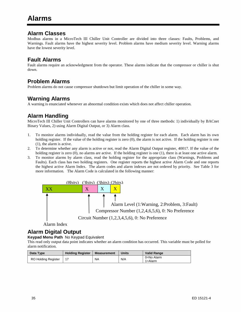
Alarms
Alarm Classes Modbus alarms in a MicroTech III Chiller Unit Controller are divided into three classes: Faults, Problems, and Warnings. Fault alarms have the highest severity level. Problem alarms have medium severity level. Warning alarms have the lowest severity level.
Fault Alarms Fault alarms require an acknowledgment from the operator. These alarms indicate that the compressor or chiller is shut down.
Problem Alarms Problem alarms do not cause compressor shutdown but limit operation of the chiller in some way.
Warning Alarms A warning is enunciated whenever an abnormal condition exists which does not affect chiller operation.
Alarm Handling MicroTech III Chiller Unit Controllers can have alarms monitored by one of three methods: 1) individually by BACnet Binary Values, 2) using Alarm Digital Output, or 3) Alarm class.
1. To monitor alarms individually, read the value from the holding register for each alarm. Each alarm has its ownholding register. If the value of the holding register is zero (0), the alarm is not active. If the holding register is one(1), the alarm is active.
2. To determine whether any alarm is active or not, read the Alarm Digital Output register, 40017. If the value of theholding register is zero (0), no alarms are active. If the holding register is one (1), there is at least one active alarm.
3. To monitor alarms by alarm class, read the holding register for the appropriate class (Warnings, Problems andFaults). Each class has two holding registers. One register reports the highest active Alarm Code and one reportsthe highest active Alarm Index. The alarm codes and alarm indexes are not ordered by priority. See Table 3 formore information. The Alarm Code is calculated in the following manner:
Alarm Digital Output Keypad Menu Path No Keypad Equivalent This read only output data point indicates whether an alarm condition has occurred. This variable must be polled for alarm notification.
Data Type Holding Register Measurement Units Valid Range
RO Holding Register 17 NA N/A 0=No Alarm 1=Alarm
XX(8bits)
Alarm Index
X X X(3bits) (3bits) (2bits)
Circuit Number (1,2,3,4,5,6), 0: No PreferenceCompressor Number (1,2,4,6,5,6), 0: No Preference
Alarm Level (1:Warning, 2:Problem, 3:Fault)
35 ED 15121-4

Clear Alarms - Network Keypad Menu Path No Keypad Equivalent This read/write input network variable clears all active alarms. Many alarms are automatically clearing alarms. Of the alarms that need to be manually cleared, the alarms listed below cannot be cleared from the network: • COMPRESSOR SHUTDOWN - Evaporator Pressure Low Circuit #n Compressor #n Fault• COMPRESSOR SHUTDOWN - Condenser Pressure High Circuit #n Compressor #n Fault• COMPRESSOR SHUTDOWN - Motor Temperature High Circuit #n Compressor #n Fault• UNIT SHUTDOWN – Evaporator Leaving Water Temp Low (Freeze)• COMPRESSOR SHUTDOWN - Mechanical High Pressure Trip Circuit #n Compressor #n Fault• COMPRESSOR SHUTDOWN - Mechanical Low Pressure Trip Circuit #n Compressor #n Fault
The default is Null, which will cause Normal to be used provided nothing else is writing to this point. This register is ignored by the unit controller if Chiller Local/Remote is set to Local.
Data Type Holding Register Measurement Units Valid Range
RW Holding Register 10 NA N/A 0=Normal 1=Clear Alarm 2=Null
Active Alarms Tables 12-14 show the registers needed to read each individual alarm, the alarm index, and the alarm code.
Table 12. Modbus Warning Alarms
Warning Alarms
Alarm Class Monitoring Individual Alarm Monitoring Holding Registers (0=Normal, 1=Alarm)
Alarm Description Alarm Index (Holding Register 28)
Alarm Code (Holding Register 31)
2 513 366 Evaporator Entering Water Temperature Sensor Failure 8 2049 377 Bad setpoint override input 9 2305 378 Bad demand limit input
11 2817 740 Unit Power Restore1
12
3105 741 Circuit Failed Pumpdown - Circuit #1 3137 742 Circuit Failed Pumpdown - Circuit #2 3169 743 Circuit Failed Pumpdown - Circuit #3 3201 744 Circuit Failed Pumpdown - Circuit #4
13 3329 745 External Event 14 3585 814 Bad Current Limit Input 15 3841 815 Option Controller Communication Failed
16 4128 825 Low Refrigerant Charge – Circuit #1 4160 826 Low Refrigerant Charge – Circuit #2 4192 827 Low Refrigerant Charge – Circuit #3
17 4352 828 Chiller Network Communication Failure 1 This alarm is only available in AWS versions 2507500204 or earlier. On older revisions of AWS, the individual alarm monitoring holding register will always read zero.
Table 13. Modbus Problem Alarms
Problem Alarms
Alarm Class Monitoring Individual Alarm Monitoring Holding Registers (0=Normal, 1=Alarm)
Alarm Description Alarm Index (Holding Register 29)
Alarm Code (Holding Register 32)
64
16418 384 RESTART DELAYED - Power Loss While Running Circuit #1 16450 385 RESTART DELAYED - Power Loss While Running Circuit #2 16482 386 RESTART DELAYED - Power Loss While Running Circuit #3 16514 387 RESTART DELAYED - Power Loss While Running Circuit #4
65 16642 388 START INHIBITED - Ambient Temperature Low 67 17168 390 INHIBIT LOAD – Condenser Pressure High Circuit #11
36 ED 15121-4

Problem Alarms
Alarm Class Monitoring Individual Alarm Monitoring Holding Registers (0=Normal, 1=Alarm)
Alarm Description Alarm Index (Holding Register 29)
Alarm Code (Holding Register 32)
17218 391 INHIBIT LOAD – Condenser Pressure High Circuit #21 17250 392 INHIBIT LOAD – Condenser Pressure High Circuit #31 17282 393 INHIBIT LOAD – Condenser Pressure High Circuit #41
69
17698 395 UNLOAD – Condenser Pressure High Circuit #11 17730 396 UNLOAD – Condenser Pressure High Circuit #21
17762 397 UNLOAD – Condenser Pressure High Circuit #31 17794 398 UNLOAD – Condenser Pressure High Circuit #41
76
19490 411 INHIBIT LOAD - Evaporator Pressure Low Circuit #11 19522 412 INHIBIT LOAD - Evaporator Pressure Low Circuit #21 19554 413 INHIBIT LOAD - Evaporator Pressure Low Circuit #31 19586 414 INHIBIT LOAD - Evaporator Pressure Low Circuit #41
78
20002 416 UNLOAD - Evaporator Pressure Low Circuit #11 20034 417 UNLOAD - Evaporator Pressure Low Circuit #21 20066 418 UNLOAD - Evaporator Pressure Low Circuit #31 20098 419 UNLOAD - Evaporator Pressure Low Circuit #41
79 20262 420 UNLOAD - Compressor Motor Current High Circuit #1, Comp #11 20294 422 UNLOAD - Compressor Motor Current High Circuit #2, Comp #11 20326 424 UNLOAD - Compressor Motor Current High Circuit #3, Comp #11
81 20738 575 PUMP #2 START ATTEMPTED - Evaporator Pump #1 Failure 82 20994 576 PUMP #1 START ATTEMPTED - Evaporator Pump #2 Failure
84
21542 780 INHIBIT LOAD - Compressor Motor Current High Circuit #1, Comp #11
21574 782 INHIBIT LOAD - Compressor Motor Current High Circuit #2, Comp #11
21606 784 INHIBIT LOAD - Compressor Motor Current High Circuit #3, Comp #11
1 These alarms are only available in AWS versions 2507500204 or earlier. On older revisions of AWS, the individual alarm monitoring holding register will always read zero.
Table 14. Modbus Fault Alarms
Fault Alarms
Alarm Class Monitoring Individual Alarm Monitoring Holding Registers (0=Normal, 1=Alarm)
Alarm Description Alarm Index (Holding Register 30)
Alarm Code (Holding Register 33)
127
32551 440 COMP SHUTDOWN - Low pressure ratio Circuit #1, Comp #1 32583 442 COMP SHUTDOWN - Low pressure ratio Circuit #2, Comp #1 32615 444 COMP SHUTDOWN - Low pressure ratio Circuit #3, Comp #1 32647 445 COMP SHUTDOWN - Low pressure ratio Circuit #4, Comp #1
128 32771 446 UNIT SHUTDOWN - Outside Air Temp Sensor Fault
129 33063 447 COMPRESSOR SHUTDOWN - Current Overload Trip Circuit #1, Comp #1 33095 449 COMPRESSOR SHUTDOWN - Current Overload Trip Circuit #2, Comp #1 33127 451 COMPRESSOR SHUTDOWN - Current Overload Trip Circuit #3, Comp #1
133 34087 466 COMP SHUTDOWN– Motor Protector Trip Circuit 1 Comp 1 34119 468 COMP SHUTDOWN– Motor Protector Trip Circuit 2 Comp 1
135
34599 478 COMP SHUTDOWN – Motor Temp High Circuit #1, Comp #1 34631 480 COMP SHUTDOWN – Motor Temp High Circuit #2, Comp #1 34663 482 COMP SHUTDOWN – Motor Temp High Circuit #3, Comp #1 34695 483 COMP SHUTDOWN – Motor Temp High Circuit #4, Comp #1
136
34855 734 COMP SHUTDOWN – Motor Temp Sensor Fault Circuit #1, Comp #1 34887 736 COMP SHUTDOWN – Motor Temp Sensor Fault Circuit #2, Comp #1 34919 738 COMP SHUTDOWN – Motor Temp Sensor Fault Circuit #3, Comp #1 34951 739 COMP SHUTDOWN – Motor Temp Sensor Fault Circuit #4, Comp #1
142
36387 509 CIRCUIT SHUTDOWN – Condenser Pressure Sensor Circuit #1 Fault 36391 509 COMP SHUTDOWN - Condenser Pressure Sensor Fault Circuit #1, Comp #1 36419 511 CIRCUIT SHUTDOWN – Condenser Pressure Sensor Circuit #2 Fault 36423 511 COMP SHUTDOWN - Condenser Pressure Sensor Fault Circuit #2, Comp #1 36455 513 COMP SHUTDOWN - Condenser Pressure Sensor Fault Circuit #3, Comp #1 36487 514 COMP SHUTDOWN - Condenser Pressure Sensor Fault Circuit #4, Comp #1
145 37155 517 CIRCUIT SHUTDOWN – Condenser Pressure High Trip Circuit 1 Fault 37159 517 COMP SHUTDOWN - Condenser Pressure High Circuit #1, Comp #1
37 ED 15121-4

Fault Alarms
Alarm Class Monitoring Individual Alarm Monitoring Holding Registers (0=Normal, 1=Alarm)
Alarm Description Alarm Index (Holding Register 30)
Alarm Code (Holding Register 33)
37187 519 CIRCUIT SHUTDOWN – Condenser Pressure High Trip Circuit 2 Fault 37191 519 COMP SHUTDOWN - Condenser Pressure High Circuit #2, Comp #1 37223 521 COMP SHUTDOWN - Condenser Pressure High Circuit #3, Comp #1 37255 522 COMP SHUTDOWN - Condenser Pressure High Circuit #4, Comp #1
147
37671 529 COMP SHUTDOWN - Discharge Temp Sensor Fault Circuit #1, Comp #1 37703 531 COMP SHUTDOWN - Discharge Temp Sensor Fault Circuit #2, Comp #1 37735 533 COMP SHUTDOWN - Discharge Temp Sensor Fault Circuit #3, Comp #1 37767 534 COMP SHUTDOWN - Discharge Temp Sensor Fault Circuit #4, Comp #1
148
37927 535 COMP SHUTDOWN - Discharge Temp High Circuit #1, Comp #1 37959 537 COMP SHUTDOWN - Discharge Temp High Circuit #2, Comp #1 37991 539 COMP SHUTDOWN - Discharge Temp High Circuit #3, Comp #1 38023 540 COMP SHUTDOWN - Discharge Temp High Circuit #4, Comp #1
150 38403 542 UNIT SHUTDOWN - Evaporator Water Flow Loss 151 38659 543 UNIT SHUTDOWN - Evaporator Leaving Water Temp Low (Freeze)
153
39203 545 CIRCUIT SHUTDOWN – Low Evaporator Pressure Trip Circuit 1 Fault 39207 545 COMP SHUTDOWN - Evaporator Pressure Low Circuit #1, Comp #1 39235 547 CIRCUIT SHUTDOWN – Low Evaporator Pressure Trip Circuit 2 Fault 39239 547 COMP SHUTDOWN - Evaporator Pressure Low Circuit #2, Comp #1 39271 549 COMP SHUTDOWN - Evaporator Pressure Low Circuit #3, Comp #1 39303 550 COMP SHUTDOWN - Evaporator Pressure Low Circuit #4, Comp #1
155
39715 552 CIRCUIT SHUTDOWN – Evaporator Pressure Sensor Circuit #1 Fault 39719 552 COMP SHUTDOWN - Evaporator Pressure Sensor Fault Circuit #1 Comp #1 39747 554 CIRCUIT SHUTDOWN – Evaporator Pressure Sensor Circuit #2 Fault 39715 554 COMP SHUTDOWN - Evaporator Pressure Sensor Fault Circuit #1 Comp #1 39783 556 COMP SHUTDOWN - Evaporator Pressure Sensor Fault Circuit #1 Comp #1 39815 557 COMP SHUTDOWN - Evaporator Pressure Sensor Fault Circuit #1 Comp #1
161
41225 583 COMP LOCKOUT - Number of Allowed Re-Starts Exceeded Circuit #1, Comp#1
41827 585 COMP LOCKOUT - Number of Allowed Re-Starts Exceeded Circuit #2, Comp#1
41319 587 COMP LOCKOUT - Number of Allowed Re-Starts Exceeded Circuit #3, Comp#1
41351 588 COMP LOCKOUT - Number of Allowed Re-Starts Exceeded Circuit #4, Comp#1
162 41475 589 UNIT SHUTDOWN - Evaporator Leaving Water Temp Sensor Fault 163 41731 755 Evaporator Entering Water Temperature Sensor Failure
166 42535 601 COMP SHUTDOWN - Mechanical High Pressure Trip Circuit #1, Comp #1 42567 603 COMP SHUTDOWN - Mechanical High Pressure Trip Circuit #2, Comp #1 42599 605 COMP SHUTDOWN - Mechanical High Pressure Trip Circuit #3, Comp #1 42631 606 COMP SHUTDOWN - Mechanical High Pressure Trip Circuit #4, Comp #1
172
44071 637 COMPRESSOR SHUTDOWN - Oil Delta Pressure High Circuit #1, Comp #1 44103 639 COMPRESSOR SHUTDOWN - Oil Delta Pressure High Circuit #2, Comp #1 44135 641 COMPRESSOR SHUTDOWN - Oil Delta Pressure High Circuit #3, Comp #1 44167 642 COMPRESSOR SHUTDOWN - Oil Delta Pressure High Circuit #4, Comp #1
173
44327 643 COMP SHUTDOWN - Oil Feed Pressure Sensor Fault Circuit #1, Comp #1 44359 645 COMP SHUTDOWN - Oil Feed Pressure Sensor Fault Circuit #2, Comp #1 44391 647 COMP SHUTDOWN - Oil Feed Pressure Sensor Fault Circuit #3, Comp #1 44423 648 COMP SHUTDOWN - Oil Feed Pressure Sensor Fault Circuit #4, Comp #1
176
45059 661 SHUTDOWN – Phase Voltage Protection (Unit) 45091 751 SHUTDOWN – Phase Voltage Protection Circuit #1 45123 752 SHUTDOWN – Phase Voltage Protection Circuit #2 45155 753 SHUTDOWN – Phase Voltage Protection Circuit #3 45187 754 SHUTDOWN – Phase Voltage Protection Circuit #4
177
45351 662 COMP SHUTDOWN - Starter Fault Compressor Circuit #1, Comp #1 45383 664 COMP SHUTDOWN - Starter Fault Compressor Circuit #2, Comp #1 45415 666 COMP SHUTDOWN - Starter Fault Compressor Circuit #3, Comp #1 45447 667 COMP SHUTDOWN - Starter Fault Compressor Circuit #4, Comp #1
183
46887 698 COMP SHUTDOWN - Suction Temp Sensor Fault Circuit #1, Comp #1 46919 700 COMP SHUTDOWN - Suction Temp Sensor Fault Circuit #2, Comp #1 46951 702 COMP SHUTDOWN - Suction Temp Sensor Fault Circuit #3, Comp #1 46983 703 COMP SHUTDOWN - Suction Temp Sensor Fault Circuit #4, Comp #1
187 47911 717 COMP SHUTDOWN - Mechanical Low Pressure Trip Circuit #1, Comp #1
38 ED 15121-4

Fault Alarms
Alarm Class Monitoring Individual Alarm Monitoring Holding Registers (0=Normal, 1=Alarm)
Alarm Description Alarm Index (Holding Register 30)
Alarm Code (Holding Register 33)
47943 719 COMP SHUTDOWN - Mechanical Low Pressure Trip Circuit #2, Comp #1 47975 721 COMP SHUTDOWN - Mechanical Low Pressure Trip Circuit #3, Comp #1 48007 722 COMP SHUTDOWN - Mechanical Low Pressure Trip Circuit #4, Comp #1
188
48131 746 Controller board offline – Unit
48163 723 Controller board offline Circuit #1 (Circuit number describes Control board number)
48195 724 Controller board offline Circuit #2 (Circuit number describes Control board number)
48227 725 Controller board offline Circuit #3 (Circuit number describes Control board number)
48259 726 Controller board offline Circuit #4 (Circuit number describes Control board number)
189
48419 747 COMP SHUTDOWN – No Pressure Change After Start Circuit #1 48451 748 COMP SHUTDOWN – No Pressure Change After Start Circuit #2 48483 749 COMP SHUTDOWN – No Pressure Change After Start Circuit #3 48515 750 COMP SHUTDOWN – No Pressure Change After Start Circuit #4
190
48675 711 COMP SHUTDOWN – No Pressure At Startup Circuit #1 48707 712 COMP SHUTDOWN – No Pressure At Startup Circuit #2 48739 713 COMP SHUTDOWN – No Pressure At Startup Circuit #3 48771 714 COMP SHUTDOWN – No Pressure At Startup Circuit #4
191
48935 756 COMP SHUTDOWN - Slide position sensor fault Circuit #1, Comp#1 48967 758 COMP SHUTDOWN - Slide position sensor fault Circuit #2, Comp#1 48999 760 COMP SHUTDOWN - Slide position sensor fault Circuit #3, Comp#1 49031 761 COMP SHUTDOWN - Slide position sensor fault Circuit #4, Comp#1
192 49155 798 UNIT STOP – Emergency Stop Alarm 193 49411 799 UNIT STOP – Evaporator Water Temperature Inverted 194 49667 800 UNIT STOP – External Alarm 195 49923 590 Evaporator Leaving Water Temperature 1 Sensor Fault 196 50179 591 Evaporator Leaving Water Temperature 2 Sensor Fault 197 50435 592 CIRCUIT SHUTDOWN - Evaporator 1 Freeze Protection 198 50691 593 CIRCUIT SHUTDOWN - Evaporator 2 Freeze Protection
199
50983 762 COMPRESSOR SHUTDOWN - COMPRESSOR VFD Fault Circuit #1, Comp #1
51015 764 COMPRESSOR SHUTDOWN - COMPRESSOR VFD Fault Circuit #2, Comp #1
51047 766 COMPRESSOR SHUTDOWN - COMPRESSOR VFD Fault Circuit #3, Comp #1
200
51239 768 COMP SHUTDOWN - COMPRESSOR VFD Over Heat Fault Circuit #1, Comp #1
51271 770 COMP SHUTDOWN - COMPRESSOR VFD Over Heat Fault Circuit #2, Comp #1
51303 772 COMP SHUTDOWN - COMPRESSOR VFD Over Heat Fault Circuit #3, Comp #1
201
51495 774 COMP SHUTDOWN-COM ERROR With COMPRESSOR VFD Circuit #1, Comp #1
51527 776 COMP SHUTDOWN-COM ERROR With COMPRESSOR VFD Circuit #2, Comp #1
51559 778 COMP SHUTDOWN-COM ERROR With COMPRESSOR VFD Circuit #3, Comp #1
202 51751 808 COMP SHUTDOWN-Low Discharge Superheat Circuit #1, Comp #1 51783 810 COMP SHUTDOWN -Low Discharge Superheat Circuit #2, Comp #1 51815 812 COMP SHUTDOWN -Low Discharge Superheat Circuit #3, Comp #1
228 58371 816 UNIT STOP - PVM GFP Fault 58403 817 CIRCUIT SHUTDOWN- PVM GFP Circuit 1 Fault 58435 818 CIRCUIT SHUTDOWN- PVM GFP Circuit 2 Fault
230 58915 822 COMP SHUTDOWN-Refrig Charge Circuit #1 58947 823 COMP SHUTDOWN-Refrig Charge Circuit #2 58979 824 COMP SHUTDOWN-Refrig Charge Circuit #3
39 ED 15121-4

Appendix A: ASCII Characters Conversion Table This table lists the ASCII characters and their decimal and hexadecimal numbers. The MicroTech III Chiller Unit Controller does not support the characters in boldface type. Also, non-printing characters, with the exception of the (Space) character, are not listed in this table and are not supported. Characters not supported are translated to a space.
Char Decimal Hexadecimal Char Decimal Hexadecimal Char Decimal Hexadecimal
(Space) 32 0x20 @ 64 0x40 ` 96 0x60 ! 33 0x21 A 65 0x41 a 97 0x61 “ 34 0x22 B 66 0x42 b 98 0x62 # 35 0x23 C 67 0x43 c 99 0x63 $ 36 0x24 D 68 0x44 d 100 0x64 % 37 0x25 E 69 0x45 e 101 0x65 & 38 0x26 F 70 0x46 f 102 0x66 ‘ 39 0x27 G 71 0x47 g 103 0x67 ( 40 0x28 H 72 0x48 h 104 0x68 ) 41 0x29 I 73 0x49 I 105 0x69 * 42 0x2a J 74 0x4a j 106 0x6a + 43 0x2b K 75 0x4b k 107 0x6b ‘ 44 0x2c L 76 0x4c l 108 0x6c - 45 0x2d M 77 0x4d m 109 0x6d . 46 0x2e N 78 0x4e n 110 0x6e / 47 0x2f O 79 0x4f o 111 0x6f 0 48 0x30 P 80 0x50 p 112 0x70 1 49 0x31 Q 81 0x51 q 113 0x71 2 50 0x32 R 82 0x52 r 114 0x72 3 51 0x33 S 83 0x53 s 115 0x73 4 52 0x34 T 84 0x54 t 116 0x74 5 53 0x35 U 85 0x55 u 117 0x75 6 54 0x36 V 86 0x56 v 118 0x76 7 55 0x37 W 87 0x57 w 119 0x77 8 56 0x38 X 88 0x58 x 120 0x78 9 57 0x39 Y 89 0x59 y 121 0x79 : 58 0x3a Z 90 0x5a z 122 0x7a ; 59 0x3b [ 91 0x5b { 123 0x7b < 60 0x3c \ 92 0x5c | 124 0x7c = 61 0x3d ] 93 0x5d } 125 0x7d > 62 0x3e ^ 94 0x5e ~ 126 0x7e ? 63 0x3f _ 95 0x5f
40 ED 15121-4
Index A
Active Alarms ............................................................. 36 Active Capacity Limit Output ........................ 10, 11, 24 Active Setpoint ............................................... 10, 11, 24 Actual Capacity .............................................. 10, 11, 24 Alarm Data Points ...................................................... 19 Alarm Digital Output ................................ 10, 11, 24, 35 Application Software Version .............................. 18, 25 Application Version.................................................... 10
C
Capacity Limit Setpoint - Network ................ 10, 16, 25 Chiller Capacity Limited ................................ 10, 11, 25 Chiller Current ...................................................... 10, 25 Chiller Data Points .................................................... 11 Chiller Enable Output ..................................... 10, 11, 26 Chiller Enable Setpoint ................................... 10, 11, 26 Chiller Local/Network ................................................ 10 Chiller Local/Remote ........................................... 11, 26 Chiller Location .............................................. 10, 18, 26 Chiller Mode Output....................................... 10, 11, 26 Chiller Mode Setpoint - Network ......................... 16, 27 Chiller Model ................................................. 10, 18, 27 Chiller Network Communication Failure Warning .... 10 Chiller On/Off ................................................ 10, 11, 27 Chiller Status ........................................................ 10, 27 Chiller Status (Chiller Run Mode) .............................. 11 Circuit Data Points .................................................... 17 Clear Alarms - Network ............................. 9, 11, 27, 36 COMP SHUTDOWN- Refrig Charge Circuit #n Fault
................................................................................ 20 Compressor Current.................................. 10, 17, 18, 28 Compressor Data Points ............................................ 17 Compressor Discharge Refrigerant Temperature 10, 28,
33 Compressor Percent RLA ......................... 10, 17, 18, 28 Compressor Power ................................... 10, 17, 18, 28 Compressor Run Hours ............................ 10, 17, 18, 29 Compressor Starts ..................................... 10, 17, 18, 29 Compressor Suction Refrigerant Temperature ..... 10, 29 Compressor Voltage ................................. 10, 17, 18, 30 Condenser Refrigerant Pressure ..................... 10, 17, 30 Condenser Saturated Refrigerant Temperature .... 10, 17,
30
Cool Setpoint - Network ................................. 10, 16, 30 Current Date & Time ............................................ 18, 31
E
Evaporator Entering Fluid Temperature ......... 10, 11, 31 Evaporator Flow Switch Status ............................. 10, 31 Evaporator Leaving Fluid Temperature .......... 10, 11, 31 Evaporator Pump Run Hours .......................... 10, 18, 31 Evaporator Pump Status .................................. 10, 18, 32 Evaporator Refrigerant Pressure ..................... 10, 17, 32 Evaporator Saturated Refrigerant Temperature ... 10, 17,
32
F
Fault Alarm Code .................................................. 10, 32 Fault Alarm Index ................................................. 10, 32
I
Ice Setpoint - Network .................................... 10, 16, 33
L
Low Refrigerant Charge – Circuit #n Warning ........... 20
M
Miscellaneous Data Points......................................... 18
O
Oil Feed Pressure ........................................................ 10 Outdoor Air Temperature ................................ 10, 11, 33
P
Problem Alarm Code ............................................ 10, 33 Problem Alarm Index ............................................ 10, 33 Pump Data Points ...................................................... 18
R
Run Enabled .................................................... 10, 11, 34
U
Units ................................................................ 10, 18, 34
W
Warning Alarm Code ............................................ 10, 34 Warning Alarm Index ........................................... 10, 34
41 ED 15121-4

This document contains the most current product information as of this printing. For the most up-to-date product information, please go to www.DaikinApplied.com.
42 ED 15121-4
Daikin Applied Solutions800.432.1342www.DaikinApplied.com