Chiller Application Guidelit.daikinapplied.com/bizlit/DocumentStorage/AirCooledChiller/... ·...
95
Chiller Application Guide People and ideas you can trust. ™ Fundamentals of Water and Air Cooled Chillers
Transcript of Chiller Application Guidelit.daikinapplied.com/bizlit/DocumentStorage/AirCooledChiller/... ·...

←TR
IM
Chiller Application Guide
People and ideas you can trust.™
Fundamentals of Water and Air Cooled Chillers

Application Guide AG 31-003-4 1
Table of Contents
Table of Contents.................................................................................................................................... 1
Introduction ............................................................................................................................................ 3
Using This Guide .............................................................................................................................. 3
Basic System ........................................................................................................................................... 3
Chiller Basics .................................................................................................................................... 3
Piping Basics..................................................................................................................................... 7
Pumping Basics ............................................................................................................................... 11
Cooling Tower Basics ..................................................................................................................... 15
Load Basics ..................................................................................................................................... 20
Control Valve Basics ....................................................................................................................... 21
Loop Control Basics ....................................................................................................................... 23
Piping Diversity .............................................................................................................................. 24
Water Temperatures and Ranges ........................................................................................................ 26
Supply Air Temperature .................................................................................................................. 26
Chilled Water Temperature Range .................................................................................................. 26
Condenser Water Temperature Range ............................................................................................. 27
Temperature Range Trends ............................................................................................................. 27
Chiller Types ......................................................................................................................................... 29
Air Cooled Chillers ......................................................................................................................... 29
Water Cooled Chillers ..................................................................................................................... 30
Winter Operation............................................................................................................................. 31
Dual Compressor and VFD Chillers ................................................................................................... 33
Dual Compressor Chillers ............................................................................................................... 33
Variable Frequency Drives .............................................................................................................. 33
System Design Changes .................................................................................................................. 34
Mechanical Room Safety ..................................................................................................................... 36
Standard 15 ..................................................................................................................................... 36
Standard 34 ..................................................................................................................................... 38
Single Chiller System ........................................................................................................................... 39
Basic Operation ............................................................................................................................... 39
Basic Components .......................................................................................................................... 39
Single Chiller Sequence of Operation ............................................................................................. 40
Parallel Chiller System ........................................................................................................................ 42
Basic Operation ............................................................................................................................... 42
Basic Components .......................................................................................................................... 42
Parallel Chiller Sequence of Operation ........................................................................................... 43
Series Chillers ....................................................................................................................................... 45
Basic Operation ............................................................................................................................... 45
Basic Components .......................................................................................................................... 45

2
Application Guide AG 31-003-4
Series Chillers Sequence of Operation ............................................................................................ 46
Constant Flow Series Counterflow Chillers .................................................................................... 48
Using VFD Chillers in Series Arrangements .................................................................................. 49
System Comparison ........................................................................................................................ 51
Primary Secondary Systems................................................................................................................ 52
Basic Operation ............................................................................................................................... 52
Basic Components .......................................................................................................................... 52
Very Large Chiller Plants ................................................................................................................ 59
Chiller Plant Sequence of Operation ............................................................................................... 59
Waterside Free Cooling ....................................................................................................................... 62
Direct Waterside Free Cooling ........................................................................................................ 62
Parallel Waterside Free Cooling ...................................................................................................... 62
Series Waterside Free Cooling ........................................................................................................ 63
Waterside Free Cooling Design Approach ...................................................................................... 63
Cooling Tower Sizing ..................................................................................................................... 64
Waterside Free Cooling Sequence of Operation ............................................................................. 65
Economizers and Energy Efficiency ............................................................................................... 66
Heat Recovery and Templifiers™ ....................................................................................................... 67
Load Profiles ................................................................................................................................... 67
Heat Recovery Chillers ................................................................................................................... 68
Templifiers™ .................................................................................................................................. 71
Variable Primary Flow Design ............................................................................................................ 74
Basic Operation ............................................................................................................................... 74
Basic Components .......................................................................................................................... 74
Variable Primary Flow Sequence of Operation ............................................................................... 75
Training and Commissioning .......................................................................................................... 77
Low Delta T Syndrome ........................................................................................................................ 78
Low Delta T Example ..................................................................................................................... 78
Low Delta T Syndrome Causes and Solutions ................................................................................ 80
Other Solutions ............................................................................................................................... 81
Process Applications............................................................................................................................. 84
Process Load Profiles ...................................................................................................................... 84
Condenser Relief ............................................................................................................................. 84
Winter Design ................................................................................................................................. 85
Chilled Water Volume ..................................................................................................................... 85
Temperatures and Ranges ............................................................................................................... 85
Minimum Chilled Water Volume ........................................................................................................ 87
Estimating System Volume ............................................................................................................. 87
Conclusions ........................................................................................................................................... 90
References ............................................................................................................................................. 91

Application Guide AG 31-003-4 3
Introduction
Using chilled water to cool a building or process is efficient and flexible. A two-inch Schedule 40 pipe
of chilled water can supply as much comfort cooling as 42" diameter round air duct. The use of
chillers allows the design engineer to produce chilled water in a central building location or even on
the roof and distribute the water economically and without the use of large duct shafts. Chilled water
also provides accurate temperature control that is especially useful for variable air volume (VAV)
applications.
The purpose of this manual is to discuss various piping and control strategies commonly used with
chilled water systems including variable flow pumping systems. Other educational opportunities for
HVAC related topics are available from the Daikin Learning Institute.
Using This Guide This guide starts by discussing the components used in a
chilled water system. It then reviews various chiller plant
designs explaining their operation, strengths, and weaknesses.
Where appropriate, sequences of operations are provided.
Each project is unique so these sequences are just guidelines.
In addition, many sections within this guide reference
ASHRAE Standard 90.1. The corresponding ASHRAE
section numbers are provided in parentheses to direct the
reader. The sections referenced in this guide are by no means
complete. It is recommended that the reader have access to the
most recent version of Standard 90.1 as well as the User’s
Manual. The standard and manual can be purchased online at
www.ashrae.org.
The information contained within this document represents the
opinions and suggestions of Daikin Applied. Equipment, application of the equipment and system
recommendations are offered by Daikin Applied as suggestions only, and Daikin Applied does not
assume responsibility for the performance of any system designed as a result of these suggestions. The
system engineer is responsible for system design and performance.
The information in this document is not to be considered design advice. The reader is advised and
directed to consult with their own design professional and to review and comply with generally
accepted professional standards, local building codes and the appropriate design standards including,
but not limited to ANSI/ASHRAE Standard 15 and 34; and the ASME Boiler and Pressure Vessel
Code.
Basic System
Figure 1 shows a basic chilled water system with connected loads. The system consists of a chiller,
cooling tower, building cooling load, chilled water and condensing water pumps and piping. This
section will review each of the components.
Chiller Basics The chiller can be water cooled or air cooled. The air cooled chiller condensers can be either dry air or
evaporatively cooled. The compressor types typically are reciprocating, scroll, screw, or centrifugal.
The evaporator can be remote from the condensing section on air cooled units. This has the advantage
of allowing the chilled water loop to remain inside the building envelope when using an outdoor
chiller. In applications where freezing conditions can be expected, keeping the chilled water loop
inside the building avoids the need for some form of antifreeze. There can be multiple chillers in a
chilled water plant. The details of various multiple chiller plant designs will be discussed in later
sections.

4
Application Guide AG 31-003-4
The chilled water loop flows
through the evaporator of the
chiller. The evaporator is a heat
exchanger where the chilled water
transfers its sensible heat (the water
temperature drops) to the refrigerant
as latent energy (the refrigerant
evaporates or boils). The refrigerant
then gives up this heat to the
condenser of the chiller. In the case
of an air cooled chiller, this heat is
rejected to the outdoor environment
via outdoor air being drawn through
the condenser coils. For a water
cooled chiller, the refrigerant gives
up its heat to a second water loop
commonly referred to as the
condenser water loop.
Flow and Capacity Calculations For air conditioning applications, the common design conditions
1 are 44°F supply water temperature
and 54°F return water temperature resulting in a flow rate of 2.4 USgpm/ton. The temperature change
in the fluid for either the condenser or the evaporator can be described using the following formula;
Q = W x C x ΔT
Where:
Q = quantity of heat exchanged, Btu/min
W = flow rate of fluid, lb/min
C = specific heat of fluid, Btu/lb•°F
ΔT = temperature change of fluid, °F
Assuming the fluid is water, the formula takes the form of:
Q = 500 x USgpm x ΔT for Q in Btu/hr
Q = (USgpm x ΔT)/24 for Q in Tons
Most air conditioning design conditions1 are based on 75°F and 50% relative humidity (RH) in the
occupied space. The dew point for air at this condition is 55.1°F. Most HVAC designs are based on
cooling the air to this dew point to maintain the proper RH in the space. Using a 10°F approach at the
cooling coil means the supply chilled water needs to be around 44°F or 45°F.
The designer is not tied to these typical design conditions. In fact, more energy efficient solutions can
be found by modifying the design conditions, as the project requires.
Changing the chilled water flow rate directly affects the chiller's performance. Too low a flow rate
lowers the chiller efficiency and ultimately leads to laminar flow. The minimum flow rate is typically
around 3 fps (feet per second) in the evaporator tubes. Too high a flow rate leads to vibration, noise,
and tube erosion. The maximum flow rate is typically around 12 fps. The chilled water flow rate
should be maintained between these limits of 3 to 12 fps.
The condenser water flows through the condenser of the chiller. The condenser is also a heat
exchanger. In this case the heat absorbed from the building, plus the work from the compressor,
transfers from the refrigerant (condensing the refrigerant) to the condenser water (raising the water
temperature). The condenser has the same limitations to flow change as the evaporator.
1 Air Conditioning, Heating, and Refrigeration Institute, AHRI Standard 550/590, Arlington, VA.
Figure 1 - Single Chiller Loop

Application Guide AG 31-003-4 5
Chillers and Energy Efficiency Chillers are often the single largest electricity users in a building. A 1,000 ton chiller has a motor rated
at 700 hp. Improving the chiller performance has an immediate benefit to the building operating cost.
Chiller full load efficiency ratings are usually given in the form of kW/ton, COP (Coefficient of
Performance = kWcooling / kWinput) or EER (Energy Efficiency Ratio = Btucooling/kWhinput). Full load
performance is default AHRI conditions or the designer specified conditions. It is important to be
specific about operating conditions since chiller performance varies significantly at different operating
conditions.
Chiller part load performance can be given at
designer-specified conditions or the NPLV (Non-
Standard Part Load Value) can be used. The
definition of NPLV is described in full detail in
AHRI 550/590, Test Standard for Chillers.
Since buildings rarely operate at design load conditions (typically less than 2% of the time) chiller part
load performance is critical to good overall chiller plant performance. Chiller full and part load
efficiencies have improved significantly over the last 10 years (Chillers with NPLVs of 0.35 kW/ton
are available) to the point where future chiller plant energy performance will have to come from chiller
plant design.
ASHRAE Standard 90.1includes mandatory efficiency requirements2 for minimum chiller
performance. In recent versions of 90.1, different “paths” can be taken to comply with efficiencies as
seen in Figure 2. Path A has efficiencies that represent a full load machine. This means that the
majority of the hours that this chiller runs will be at full load and not at part load so the part load
efficiency does not need to be as low as Path B. Path B efficiencies allow the full load kW/ton to be
higher because of the VFD on the compressor, however, the kW/ton for the part load performance is
much better because the chiller will be performing at part load the majority of the time.
2 Copyright 2010, ASHRAE, www.ashrae.org. Reprinted by permission from ASHRAE Standard 90.1-
2010
☺Tip: To convert from COP to kW/ton;
COP = 3.516/(kW/ton)
To calculate EER = tons x 12/(total kW
input)

6
Application Guide AG 31-003-4
Figure 2 - ASHRAE Standard 90.1 Chiller Performance Table

Application Guide AG 31-003-4 7
Piping Basics The chilled water piping is usually a closed loop. A closed loop only interacts with the atmosphere at
the expansion tank. Figure 3 shows a simple closed loop system. The static pressure created by the
change in elevation is equal on both sides of the pump because the system is closed. In a closed loop,
the pump needs only to overcome the friction loss in the piping and through components. The pump
does not need to “lift” the water to the top of the
loop, just push the water through
the system.
When open cooling towers are
used in condenser piping, the
loop is considered an open loop.
The condenser pump must
overcome the friction of the
system and “lift” the water the
elevation difference from the
sump to the top of the cooling
tower as shown in Figure 4. Note
that the pump only needs to
overcome the elevation
difference of the cooling tower,
not the entire building. If no
isolating valves are used, the
water in the system will seek a
balancing point. In the case of
Figure 4, that balancing point is the
bottom of the cooling tower sump. When
the pump is shut off the water in the
upper pumping will flow backwards to
fill the sump. Special care should be
taken for these situations, such as sizing
the sump to hold the extra water in the
system or isolate that side of the loop
with a check valve.
In high-rise applications, the static
pressure can become considerable and
exceed the pressure rating of the piping
and the components such as chillers.
Standard chillers typically handle 150
psi, but the reader is advised to check
with the manufacturer. Although chillers
can be built to higher pressure ratings,
high pressure systems can become very
expensive. The next standard pressure
rating is typically 300 psi. One solution
is to use heat exchangers to isolate the chillers from the
static pressure. While this solves the pressure rating for
the chiller, it introduces another hydronic device and
another approach that affects supply water temperature
and chiller performance. Another solution is to locate
chiller plants on various floors throughout the building to
avoid exceeding the 150 psi chiller pressure rating.
Expansion Tanks An expansion tank is required in the chilled water loop to allow for the thermal expansion of the water.
Expansion tanks can be an open type, closed type with air-water interface, or closed type with a
diaphragm. The tank location will influence the type of expansion tank that should be used. Open
tanks must be located above the highest point in the system (for example, the penthouse). Air-water
☺Tip: Most chillers are rated for 150 psi
water side pressure. This should be
considered carefully for buildings over
10 stories.
Figure 4 – Open System
Figure 3 - Closed System
8
Application Guide AG 31-003-4
interface and diaphragm type tanks can be located anywhere in the system. Generally, the lower the
pressure in the tank, the smaller the tank needs to be.
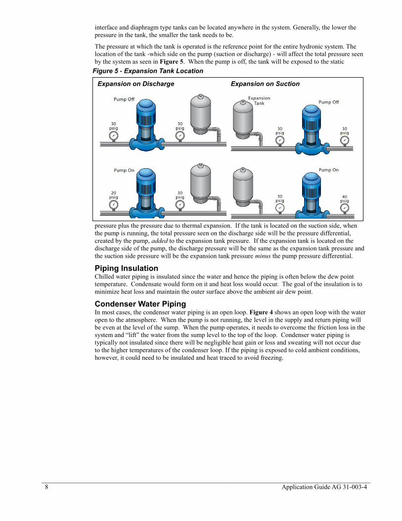
The pressure at which the tank is operated is the reference point for the entire hydronic system. The
location of the tank -which side on the pump (suction or discharge) - will affect the total pressure seen
by the system as seen in Figure 5. When the pump is off, the tank will be exposed to the static
pressure plus the pressure due to thermal expansion. If the tank is located on the suction side, when
the pump is running, the total pressure seen on the discharge side will be the pressure differential,
created by the pump, added to the expansion tank pressure. If the expansion tank is located on the
discharge side of the pump, the discharge pressure will be the same as the expansion tank pressure and
the suction side pressure will be the expansion tank pressure minus the pump pressure differential.
Piping Insulation Chilled water piping is insulated since the water and hence the piping is often below the dew point
temperature. Condensate would form on it and heat loss would occur. The goal of the insulation is to
minimize heat loss and maintain the outer surface above the ambient air dew point.
Condenser Water Piping In most cases, the condenser water piping is an open loop. Figure 4 shows an open loop with the water
open to the atmosphere. When the pump is not running, the level in the supply and return piping will
be even at the level of the sump. When the pump operates, it needs to overcome the friction loss in the
system and “lift” the water from the sump level to the top of the loop. Condenser water piping is
typically not insulated since there will be negligible heat gain or loss and sweating will not occur due
to the higher temperatures of the condenser loop. If the piping is exposed to cold ambient conditions,
however, it could need to be insulated and heat traced to avoid freezing.
Expansion on Discharge Expansion on Suction
Figure 5 - Expansion Tank Location

Application Guide AG 31-003-4 9
Reverse Return/Direct Return Piping Figure 6 shows reverse return
piping. Reverse return piping is
designed such that the path
through any load is the same
length and therefore has
approximately the same fluid
pressure drop. Reverse return
piping is inherently self-
balancing. It also requires more
piping and consequently is more
expensive.
Direct return piping results in the
load closest to the chiller plant
having the shortest path and
therefore the lowest fluid
pressure drop. Depending on the
piping design, the difference in
pressure drops between a load
near the chiller plant and a load
at the end of the piping run can be substantial. Balancing valves will be required. The advantage of
direct return piping is the cost savings of less piping.
For proper control valve selection, it is necessary to know the pressure differential between the supply
and return header (refer to Control Valve Basics). While at first it would appear with reverse return
piping, that the pressure drop would be the same for all devices, this is not certain. Changes in pipe
sizing in the main headers, different lengths and fittings all lead to different pressure differentials for
each device. When the device pressure drop is large relative to piping pressure losses, the difference is
minimized.
In direct return
piping, (Figure 7)the
pressure drops for
each device vary at
design conditions
depending on where
they are in the
system. The valve
closest to the pumps
will see nearly the
entire pump head.
Valves at the furthest
end of the loop will
see the minimum
required pressure
differential.
Assuming the
pressure differential
sensor is located at
the furthest end, all
valves in a direct
return system should
be selected for the minimum pressure differential. This is because if any one device is the only one
operating, the pressure differential controller will maintain the minimum differential across that device.
The decision whether to use direct or reverse return piping should be based on system operability vs.
first cost. Where direct return piping is used, flow-balancing valves should be carefully located so that
the system can be balanced.
Figure 6 - Reverse Return Piping
Figure 7 - Direct Return Piping

10
Application Guide AG 31-003-4
Piping and Energy Efficiency Piping materials and design have a large influence on the system pressure drop, which in turn affects
the pump work. Many of the decisions made in the piping system design will affect the operating cost
of the chiller plant every hour the plant operates for the life of the building. When viewed from this
life cycle point of view, any improvements that can lower the operating pressure drop should be
considered. Some areas to consider are:
Pipe material. Different materials have different friction factors. Steel, PVC, and copper are
typical piping materials for HVAC applications.
Pipe sizing. Smaller piping raises the pressure drop. This must be balanced against the
capital cost and considered over the lifetime of the system.
Fittings. Minimize fittings as much as possible.
Valves. Valves represent large pressure drops and can be costly. Isolation and balancing
valves should be strategically placed.
Direct return vs. Reverse return.
Piping insulation reduces heat gain into the chilled water. This has a compound effect. First, any
cooling effect that is lost due to heat gain is an additional system load on the chiller plant. Second, in
most cases, to account for the resultant temperature rise, the chilled water setpoint must be lowered to
provide the correct supply water temperature at the coil. This increases the lift on the chillers and
lowers their performance.
ASHRAE Standard 90.1 dictates the specifics of hydronic systems in a building including specifics
regarding minimum insulation that should be used on piping and how large of a pump is allowed in the
building. The most recent version of Standard 90.1 should be referenced for the most up to date
specific values. Table 1 shows the minimum piping insulation from Standard 90.13.
Table 1 - Minimum Piping Insulation as per Standard 90.1
Fluid Design Operating Temp. Range (°F)
Insulation Conductivity Nominal Pipe or Tube Size (in)
Conductivity Btu•in/(h•ft2•°F)
Mean Rating Temp °F
<1 1 to <1-1/2 1-1/2 to <4 4<8 >8
Cooling Systems (Chilled Water, Brine and Refrigerant)
40-60°F 0.21-0.27 100 0.5 0.5 1.0 1.0 1.0
<40°F 0.20-0.26 100 0.5 1.0 1.0 1.0 1.5
3 Copyright 2010, ASHRAE, www.ashrae.org. Reprinted by permission from ASHRAE Standard 90.1-
2010
Application Guide AG 31-003-4 11
Pumping Basics
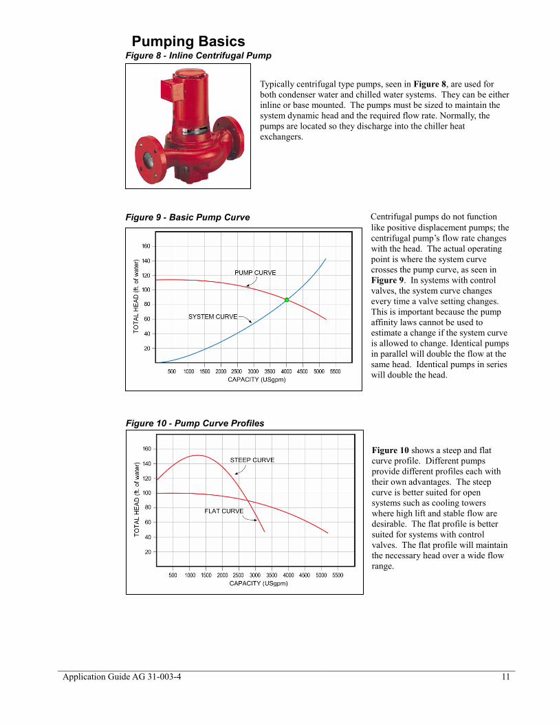
Typically centrifugal type pumps, seen in Figure 8, are used for
both condenser water and chilled water systems. They can be either
inline or base mounted. The pumps must be sized to maintain the
system dynamic head and the required flow rate. Normally, the
pumps are located so they discharge into the chiller heat
exchangers.
Centrifugal pumps do not function
like positive displacement pumps; the
centrifugal pump’s flow rate changes
with the head. The actual operating
point is where the system curve
crosses the pump curve, as seen in
Figure 9. In systems with control
valves, the system curve changes
every time a valve setting changes.
This is important because the pump
affinity laws cannot be used to
estimate a change if the system curve
is allowed to change. Identical pumps
in parallel will double the flow at the
same head. Identical pumps in series
will double the head.
Figure 10 shows a steep and flat
curve profile. Different pumps
provide different profiles each with
their own advantages. The steep
curve is better suited for open
systems such as cooling towers
where high lift and stable flow are
desirable. The flat profile is better
suited for systems with control
valves. The flat profile will maintain
the necessary head over a wide flow
range.
Figure 8 - Inline Centrifugal Pump
Figure 9 - Basic Pump Curve
Figure 10 - Pump Curve Profiles

12
Application Guide AG 31-003-4
Figure 11 shows a typical pump curve. Red lines on the pump curve represent the different diameters
of the impellers for the pumps. As the impeller increases, the amount of head that the pump can
produce increases. The blue lines symbolize the system curve and how the system changes if a valve is
opened or closed. For example, if a valve is closed, the dotted line to the left of the solid blue line
might be used to represent an increase in the head requirements of the pump. The purple lines
correspond to the break horse power of the pump. A pump with a specific impeller diameter running at
a fixed speed will require a variation in horse power as the head and flow change. While doing this, the
efficiencies of the pump can also change. These are shown in green on the pump curve. While all of
these parameters are being selected, there is also a requirement to keep enough pressure on the system
to prevent cavitation (flashing the moving fluid into a gas), which damages the pump’s impeller. This
requirement is called the Net Positive Suction Head (NPSH), shown in yellow on the pump curve.
NPSH is an important consideration with condenser pumps particularly when the chillers are in the
penthouse and the cooling towers are on the same level.
Since pumps are direct drive, the pump
curves are typically for standard motor
speeds (1200, 1800 or 3600 rpm). Once
there is a selected pump speed, the required
flow rate and head can be plotted on the
pump curve. Where this point lays will
determine what the impeller diameter,
subsequent efficiency, and break horsepower
the pump will operate at.
Multiple Pumps To provide redundancy, multiple pumps are used. Common approaches are (1) a complete full-sized
stand-by pump, or (2) the design flow is met by two pumps with a third stand-by pump sized at half the
load. When multiple pumps are used in parallel, check valves on the discharge of each pump are
required to avoid “short circuiting”. Pumps can also utilize common headers to allow one pump to
serve multiple duties (headered primary pumps serving multiple chillers). Refer to the section on
Primary Pumps for more information on primary pumps.
Figure 11 - Typical Centrifugal Pump Curve
☺Tip: For a constant system curve, the
following pump affinity laws may be used;
At constant impeller diameter (Variable speed)
RPM1 / RPM2 = gpm1 / gpm2 = (H1 )½/(H2 )
½
At constant speed (Variable impeller diameter)
D1 / D2 = gpm1 / gpm2 = (H1 )½/(H2 )
½
Application Guide AG 31-003-4 13
Variable Flow Pumps Many applications require the flow to change in response to load. Modulating the flow can be
accomplished by:
Riding the pump curve
Staging on pumps
Using variable frequency drives (VFDs)
Riding the pump curve is typically used on small systems with limited flow range. Staging on pumps
for small systems was the traditional method until VFDs. Staging pumps is a common method of
control in large chiller plants where varying the tonnage in a plant is achieved by staging on chillers.
Today, VFDs are the most common method for varying flow. They are the most efficient method as
well. System flow is usually controlled by maintaining a pressure differential between the supply and
return lines. The measuring point should be at or near the end of the pipe runs as opposed to being in
the mechanical room to reduce unnecessary pump work. This is particularly true for direct return
systems.
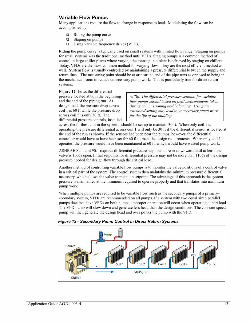
Figure 12 shows the differential
pressure located at both the beginning
and the end of the piping run. At
design load, the pressure drop across
coil 1 is 60 ft while the pressure drop
across coil 5 is only 30 ft. The
differential pressure controls, installed
across the furthest coil in the system, should be set up to maintain 30 ft. When only coil 1 is
operating, the pressure differential across coil 1 will only be 30 ft if the differential sensor is located at
the end of the run as shown. If the sensors had been near the pumps, however, the differential
controller would have to have been set for 60 ft to meet the design requirements. When only coil 1
operates, the pressure would have been maintained at 60 ft, which would have wasted pump work.
ASHRAE Standard 90.1 requires differential pressure setpoints to reset downward until at least one
valve is 100% open. Initial setpoints for differential pressure may not be more than 110% of the design
pressure needed for design flow through the critical load.
Another method of controlling variable flow pumps is to monitor the valve positions of a control valve
in a critical part of the system. The control system then maintains the minimum pressure differential
necessary, which allows the valve to maintain setpoint. The advantage of this approach is the system
pressure is maintained at the minimum required to operate properly and that translates into minimum
pump work.
When multiple pumps are required to be variable flow, such as the secondary pumps of a primary-
secondary system, VFDs are recommended on all pumps. If a system with two equal sized parallel
pumps does not have VFDs on both pumps, improper operation will occur when operating at part load.
The VFD pump will slow down and generate less head than the design conditions. The constant speed
pump will then generate the design head and over power the pump with the VFD.
Figure 12 - Secondary Pump Control in Direct Return Systems
☺Tip: The differential pressure setpoint for variable
flow pumps should based on field measurements taken
during commissioning and balancing. Using an
estimated setting may lead to unnecessary pump work
for the life of the building.

14
Application Guide AG 31-003-4
Figure 134 shows percent pumping power as a
function of percent flow. From this figure, it can be
seen that VFD pumps will not save much energy
below 33% or 20Hz. Operating pumps much below
30% starts to create problems for motors, chiller
minimum flows, etc. Since there are minimal
savings anyway, the recommended minimum
frequency is 20 Hz.
Pumps and Energy Efficiency Pump work is deceptive. Although the motors tend to be small (when compared to chiller motors),
they operate whenever the chiller operates. In a single water-cooled chiller plant with constant chilled
water flow, it is not unusual for the pumps to use two-thirds of the energy consumed by the chiller.
Optimal use of pumps can often save more energy than any other improvement to a chiller plant.
When both motors and VFDs operate
at less than 100% capacity, their
efficiency drops off. Figure 144 shows
motor and VFD efficiencies at part load.
It can be seen that over sizing motors
can lead to significantly poorer
performance than expected.
Over sizing pumps themselves also leads
to wasted energy. If the pumps produce
too much flow, the flow will be
throttled, usually with a balancing valve,
to meet the desired flow. This creates an
unnecessary pressure drop and
consumes power all the time the pump
operates. The solution in most cases, is
to trim the impeller.
ASHRAE Standard 90.1 prescribes the operating conditions of pumps and VFDs. It specifies the
maximum horsepower that is allowed in the building along with operating minimums for different
sizes. Again, the most recent version of Standard 90.1 should be referenced for the most recent
information.
4 Bernier, Michel., Bernard Bourret, 1999. Pumping Energy and Variable Speed Drives. ASHRAE
Journal, December 1999. ASHRAE. Atlanta, Ga.
Figure 13 - Pumping Power vs. Flow4
Figure 14 - Motor and VFD Efficiency at Part Load4

Application Guide AG 31-003-4 15
Cooling Tower Basics Cooling towers are used in conjunction
with water-cooled chillers. Air-cooled
chillers do not require cooling towers. A
cooling tower rejects the heat collected
from the building plus the work of
compression from the chiller. There are
two common forms used in the HVAC
industry: induced draft (Figure 15) and
forced draft (Figure 16). Induced draft
towers have a large propeller fan at the top
of the tower (discharge end) to draw air
counterflow to the water. They require
much smaller fan motors for the same
capacity than forced draft towers. Induced
draft towers are considered to be less
susceptible to recirculation, which can
result in reduced performance.
Forced draft towers have fans on the air
inlet to push air either counterflow or
crossflow to the movement of the water.
Forward curved fans are often employed.
They use more fan power than induced
draft but can provide external static
pressure when required. This can be
important if the cooling tower requires
ducting, discharge cap or other device that
creates a pressure drop.
Condenser water is dispersed through the
tower through trays or nozzles. The water
flows over fill within the tower, which
greatly increases the air-to-water surface
contact area. The water is collected into a
sump, which can be integral to the tower or
remote from the tower. The latter is
popular in freezing climates where the
condenser water can be stored indoors.
Either tower type can have single or
multiple cells. The cells can be headered together on both the supply and return side with isolation
valves to separate the sections. This approach allows more cells to be added as more chillers are
activated or to allow more tower surface area to be used by a single chiller to reduce fan work.
Typical Operating Conditions The Cooling Tower Institute (CTI) rates cooling towers at 78°F ambient wet-bulb, 85°F supply water
temperature and a 10°F range. Since it is common (but not necessary) to use a temperature range of
10°F, the cooling tower flow rate will be 3.0 gpm/ton compared to the chilled water flow rate which is
2.4 gpm/ton. The extra condenser water flow rate is required to accommodate the heat from the work
of compression. Cooling towers are very versatile and can be used over a wide range of approaches,
ranges, flows, and wetbulb temperatures. Lower condenser water temperatures can be produced in
many climates with low wet bulb temperatures which significantly improves chiller performance.
Cooling Tower Process Cooling towers expose the condenser water directly to the ambient air in a process that resembles a
waterfall. This process can cool condenser water to below ambient dry-bulb. The water is cooled by a
combination of sensible and latent cooling. A portion of the water evaporates which provides the latent
cooling. The example on below shows the cooling tower process on a psychrometric chart at AHRI
conditions. As the wet-bulb temperature drops, cooling towers rely more on sensible cooling and less
Figure 15 - Induced Draft Cooling Tower
Figure 16 - Forced Draft Cooling Tower

16
Application Guide AG 31-003-4
on latent cooling. Ambient air below freezing can hold very little moisture which leads to large
plumes; and in some cases the winter tower selection requires a larger tower than the summer
conditions. Additional care should be taken when selecting cooling towers for use in winter.
Approximately 1% of the design condenser water flow is evaporated (See the above example). A
1,000-ton chiller operating at design conditions can consume 1,800 gallons of water per hour. The
specific amount can be calculated by reviewing the psychrometric process. In locations where the cost
of water is an issue, air-cooled chillers may provide a better operating cost despite the lower chiller
performance.
Winter Operation Cooling towers that are required to work in freezing winter environments require additional care. The
condenser water must not be allowed to freeze, particularly when the tower is idle. Common solutions
include electric or steam injection heaters or a remote sump within the building envelope. The high
RH of ambient winter air results in a plume, which can frost over surrounding surfaces. Low plume
towers are available, but freezing of condenser water on the tower itself can lead to blockage and
reduced or no performance. Modulating water flow through a cooling tower (such as the use of three-
way chiller head pressure control) should be given careful consideration. In many instances this can
lead to increased possibility of freezing the tower.
Psychrometric Process for Cooling Towers
The above psychrometric chart shows the cooling tower process at AHRI conditions. Assume 1
lb. of water is cooled by 1 lb. of air. The water cools from 95F to 85F and releases 10 Btus of
heat to the air ( 1 Btu = the amount of heat required to raise the temperature of 1 lb. of water,
1F). The 10 Btus of heat raises the enthalpy of air from 41.3 Btu/lb. to 51.3 Btu/lb. and
saturates the air. The leaving air condition is 86.4F and 100% RH. The moisture content went
from 0.017 lb.w to 0.028 lb.w. This means 0.028-0.017 lb. = 0.011 of water was evaporated
which is why it is common to hear that cooling towers lose about 1% of their water flow to
evaporation. The latent heat of vaporization for water at 85F is about 1,045 Btu/lb. Multiplying
the latent heat times the amount of evaporated water (1045 x 0.011) results in 11.45 Btus of
cooling effect. Cooling the water required 10 Btus, the rest was used to cool the air sensibly.
The air entered the tower at 95F dry bulb, 78F wet bulb and left the tower at 86.4F saturated.

Application Guide AG 31-003-4 17
Water Treatment Condenser water has all the right ingredients for biological growth; it is warm, exposed to air, and
provides a surface to grow on. In addition, the constant water loss makes water treatment even more
difficult. Both chemical and ozone-based treatment systems are used. A thorough discussion on the
topic of water treatment is beyond the scope of this application guide, but it suffices to say that it is
necessary to provide the proper operation of both the tower and the chiller.
Closed Circuit Coolers Cooling towers differ from closed-circuit coolers in that closed-circuit coolers reject heat sensibly
while cooling towers reject heat latently. Consider ambient design conditions of 95°Fdb and 78°Fwb.
If closed circuit coolers are used, the condenser water must be warmer than the ambient dry-bulb
(typically 10°F warmer or 105°F). This raises the condensing pressure in the chiller and requires more
overall power for cooling. Closed circuit coolers are larger than cooling towers for the same capacity
and can be difficult to locate on the roof.
Cooling Tower Controls Cooling tower controls
provide condenser water at
the correct temperature to the
chillers. Defining correct
water temperature is very
important. Lowering the
condenser supply water
temperature (water from the
tower to the chiller)
increases the effort by the
cooling tower resulting in
more fan work, however this
improves the performance of
the chiller by offering
condenser relief. Figure 17
shows the relationship
between chiller and tower
power5. This chart shows
how the power is affected of
reduced tower air flow (higher ECWT) on the power requirement of a electric centrifugal chiller at full
load.
Table 2 shows the range of chiller improvement that can be expected by lowering the condenser water
supply temperature. The goal of cooling tower control is to find the balance point that provides the
required cooling with the least use of power by the chiller plant.
Table 2 - Chiller Performance vs. CSWT
Chiller Type Performance Improvement
(Percent kW /°F condenser water)
W/C Recip. 1.1 to 1.3
W/C Scroll 1.3 to 1.5
W/C Screw 1.6 to 1.8
W/C Centrifugal 1.0 to 1.6
W/C Centrifugal VFD 2.4 to 2.6
Absorption 1.4 to 1.5
5 Braun, J.E., and G.T. Diderrich. 1990. Near-Optimal Control of Cooling Towers For Chilled Water
Systems. ASHRAE Transactions SL-90-13-3, Atlanta, Ga.
Figure 17 - Chiller Power vs. Tower Power

18
Application Guide AG 31-003-4
Cooling towers are often provided with aquastats. This is the most basic level of control. An aquastat
is a type of temperature sensor that has a high temperature setpoint and a low temperature setpoint. If
the water in the loop reaches the high temperature, it will trigger the condenser fan to come on until the
water temperature reaches the low temperature setpoint.
Aquastats are popular for single chiller–tower arrangements because the control package can be
supplied as part of the cooling tower. The aquastat is installed in the supply (to the chiller) side of the
cooling tower. In many cases, the setpoint is 85°F, which is very poor. If aquastats are going to be
used, then a lower setpoint than 85°F should be used. One recommendation is to set the aquastat at the
minimum condenser water temperature acceptable to the chiller. The cooling tower will then operate
at maximum fan power and always provide the coldest possible (based on load and ambient wet bulb)
condenser water to the chiller until the minimum setpoint is reached. Then the tower fan work will
stage down and maintain minimum setpoint.
Figure 18 shows the 85°F setpoint and the AHRI condenser relief curve which chillers are rated at.
Maintaining 85°F condenser water, while saving cooling tower fan work, will significantly penalize the
chiller. There is some risk that without some condenser relief, the chiller may not operate at lower part
load conditions (chiller may surge). Minimum chiller setpoints are not a specific temperature. They
change depending on the chiller load. A conservative number such as 65°F is recommended.
Another method to control cooling towers dedicated to single chillers is to use the chiller controller.
Most chiller controllers today have standard outputs which can operate cooling towers, bypass valves
and pumps. The chiller controller has the advantage of knowing just how much cooling is actually
required by the chiller for optimum performance.
A method to control either single cell or multiple cell cooling towers serving multiple chillers is to base
the condenser supply water
temperature on ambient wet-bulb.
For this method, set the
condenser water setpoint at the
current ambient wet-bulb plus the
design approach temperature for
the cooling tower. The set-point
will change as the ambient wet-
bulb changes as seen in Figure
19. Limit the setpoint between
the design condenser water
temperature (typically 85°F) and
the minimum condenser water
temperature (typically 65°F).
Figure 18 – Cooling Tower Temperature Resets
Figure 19 - Minimum Setpoint with Varying Chiller Load

Application Guide AG 31-003-4 19
The wet-bulb method will provide good condenser relief for the chiller and cooling tower fan work
relief when the chiller is not operating at 100% capacity. This can be a good balance between chiller
and tower work.
Head Pressure Control of Cooling Towers Chillers that rely on oil for lubrication require a certain amount of pressure differential between the
evaporator and the condenser to effectively “pump” the oil through the system to lubricate the
bearings, gears, shaft seals, or create the seal between rotors and housing. Also, chillers that rely on
refrigerant to cool the internal electrical components such as speed drives and motor windings need
similar pressure differentials. All commercial water-cooled chillers operate on the premise that there
will be higher pressure in the condenser than in the evaporator.
An effective condenser water temperature control system, or head pressure control, is the best way to
ensure that the chiller will see enough pressure differential to start and operate correctly when there is
very little heat in the evaporator water. Minimum condenser water temperatures for start-up vary by
manufacturer and by type of technology, but all manufacturers of all types of technology recommend
effective head pressure control.
The simplest and most common method of head pressure control is a water flow sensor in the
condenser water. The chiller will not start unless this flow sensor proves that water is flowing through
the condenser bundle. Some Daikin Applied chillers offer a feature called Lenient Flow which will
allow the compressor to start for a short time before the flow sensor proves flow.
A more sophisticated control is a direct analog output from the chiller controller which can operate a
valve or a VFD to the condenser pump. The valve is generally a bypass type which bypasses condenser
water around the cooling tower so it will heat up quickly and allow the compressor to start. The
arrangements in Figure 20 are two examples of how this can be piped. Either method provides a
constant water flow rate through the condenser tube bundle. The version located close to the tower also
could be piped so that the bypassed condenser water goes directly to the tower cold water basin. This
would provide some warmth to the basin water and would help prevent freezing in cold climates but
would also require more time to heat up the condenser temperature to the appropriate level.
Another option for winter operation is to provide a sump within a heated building to accept the cold
water from the tower, leaving the tower’s normal cold water basin empty.
The head pressure control could be a two-way valve in the condenser line which would directly vary
the flow rate of condenser water entering the chiller by causing the condenser pump to “ride the pump
curve”. The effect on the condenser system is to reduce the heat transfer both in the condenser bundle
and the tower causing the refrigerant pressure to rise in the condenser. This approach has the same
effect as using the chiller’s head pressure control signal to vary the speed of the condenser pump.
Figure 20 - Condenser Bypass Valve

20
Application Guide AG 31-003-4
In all of these approaches, it is very important to establish a definite minimum flow through the
condenser so that the water flow sensor will prove flow and allow the chiller to run. A default value
for this minimum flow requirement is fifty percent of the design condenser flow rate.
The chiller controller in most Daikin chillers includes an analog output which is designed to directly
control the VFD on cooling tower fans. It has the function of maintaining a specific condenser water
temperature which leaves the cooling tower and enters the chiller condenser. The tower fan control
signal must not be confused with the tower bypass control signal which prevents low temperature
condenser water from entering the condenser (initially set for 65°F). The tower fan control can control
to either the condenser entering water temperature ECWT or to the pressure lift in the refrigeration
cycle. Either control must be set up by a Daikin Factory Service Technician. Either staged ON/OFF fan
starters (up to four fans) or a VFD can be operated by this controller.
Ultimately, the best cooling tower control designs are part of a chiller plant optimization program.
These programs monitor the weather, the building load, and the power consumption of all the
components in the chiller plant including cooling towers. Using modeling algorithms, the program
calculates the best operating point to use the least power possible and meet the requirements of the
building.
Cooling Towers and Energy Efficiency Cooling towers consume power to operate the fans. Induced draft towers should be selected since they
typically use half the fan horsepower force draft towers use. Some form of fan speed control is also
recommended such as piggyback motors, multi-speed motors or Variable Speed Drives (VFDs). In
addition, sensible control logic is required to take advantage of the variable speeds.
ASHRAE Standard 90.1 necessitates that the cooling tower fan has to be able to be turned down and
that the fan motor be limited to the specified horse power. These values can be found in the most recent
version of the standard. Depending on special situations, there are situations where the condenser fan
does not need to have the capability to turn down. Again, these special situations should be reviewed in
the most current version of the standard.
Load Basics
Chilled water coils are used to transfer the heat from the building air to the chilled water. The coils can
be located in air handling units, fan coils, induction units, etc (see Figure 21). The air is cooled and
dehumidified as it passes through the coils. The chilled water temperature rises as the water takes heat
out of the air that is passing over the coil.
Cooling coil performance is not linear with flow. Cooling coils perform 75% cooling with only 50%
chilled water flow and 40% cooling with only 20% flow. As well, the leaving water temperature will
approach the entering air temperature as the load is reduced.
Process loads can reject heat in the chilled water in a variety of ways. A common process load is a
cooling jacket in machinery such as injection molding equipment. Here the chilled water absorbs the
sensible heat of the process.
Figure 21 - Air Handling Equipment

Application Guide AG 31-003-4 21
Control Valve Basics Control valves are used to maintain space temperature conditions by altering chilled water flow.
Valves can be broken down into groups in several ways. Valves can be two-position or modulating.
Two-position valves are either on or off and the control comes from time weighting. The percentage
that the valve is open over a certain time period dictates the amount of cooling that the cooling coil
actually does. Modulating valves vary the flow in response to a control signal such as a leaving air
temperature.
Valves can also be classified as two-way or three-way type. Two-way valves throttle flow while three
divert flow. Refer to the section on Piping Diversity for further explanation. There are several
different physical types of valves. Globe valves, ball valves, and butterfly valves are all commonly
used in the HVAC industry.
Different kinds of valves have different valve characteristics. Common characteristic types include
linear, equal percentage, and quick opening. Control valves used with cooling coils need to have a
performance characteristic that is “opposite” to the coil. Equal percentage control valves are typically
used for two-way applications. For three-way applications, equal percentage is used on the terminal
port and linear is used on the bypass port.
Figure 22 shows an equal percentage control valve properly matched to a cooling coil. The result is
that the valve stem movement is linear with the cooling coil capacity. In other words, a valve stroked
50% will provide 50% cooling.
Sizing Control Valves Control valves must be sized correctly for the chilled water system to operate properly. An incorrectly
sized control valve cannot only mean the device it serves will not operate properly; it can also lead to
system-wide problems such as low delta T syndrome.
Control valves are typically sized based on the required valve coefficient, Cv. The Cv is the amount of
60°F water that will flow through the valve with a 1 psi pressure drop. The formula is:
G = Cv *ΔP½
Where:
G = flow through the valve, USgpm
Cv = valve coefficient
ΔP = differential pressure required across the control valve, psi
The required flow at a control valve is defined by the needs on the device (fan coil, unit ventilator, or
AHU) it serves. Cv values for valves are published by valve manufacturers. The required pressure
differential through the valve is the difficult parameter to define. This is because the system can be
either a reverse return piping system or a direct return piping system. The difference in the system
selection will cause the pressure drops to be different at the same place in the system. While selecting
control valves, attention should be given to this particular detail.
Figure 22 - Coil and Control Valve Characteristic Curves

22
Application Guide AG 31-003-4
Figure 23 shows typical pressure drops
from the supply to the return line for a
cooling coil. For a modulating valve, the
valve pressure drop should be as large of
a percentage as possible when compared
to the system pressure drop; preferably
over 50%. The reason is to maintain
valve authority. For on-off control, any
valve can be used as long as it can pass
the required flow rate with the pressure
differential available.
Valve Authority As a control valve closes, the pressure
drop across the valve increases so that
when the valve is completely closed,
the differential pressure drop across the
valve matches the pressure drop from
the supply to the return line. This
pressure drop is known as ΔPMax .
When the valve is completely open, the
pressure drop across the valve is at its
lowest point and is referred to ΔPMin.
The ratio of ΔPMin to ΔPMax is the valve
authority, β. The increase in pressure
drop across the valve as it closes is
important to note. Valves are rated
based on a constant pressure drop, as
the pressure drop shifts, the
performance of the valve changes. The method to minimize the change in valve performance is to
maintain the valve authority (β) above 0.5.
Figure 24 shows the change in the valve
characteristic that occurs at different valve
authorities. Since the goal is to provide a
valve with a performance characteristic that
is the opposite of a coil characteristic (See
Figure 22), it is important to maintain the
valve authority above 0.5.
Rangeablity Rangeablity is a measure of the turndown a control valve can provide. The larger the range, the better
the control at low loads. Typical ranges for control valves are 15:1 to 50:1.
Control Valve Location in Systems Proper valve selection requires knowing the pressure drop from the supply to the return wherever the
device is located. This information is typically not made available to the controls contractor which
often leads to guessing. One solution would be for the designer to provide the required Cv for each
valve. Another solution would be to provide the estimated pressure drops for each valve. Because the
pressure drop from the supply to the return changes throughout the system, it can be expected that
different valves, each with a different Cv, will be required. Even if all the coil flows and pressure drops
were identical, the valves should change depending on location in the system. Lack of attention to this
detail can lead to low delta T syndrome (refer to Low Delta T Syndrome) that can be very difficult to
resolve.
Figure 23 - Pressure Drops and Cv
☺Tip: When calculating valve Cv to size valves, use at
least 50% of the system pressure drop from the supply to
the return line to maintain good valve authority. In most
cases, a properly sized control valve will be smaller than
the line size it is installed in.
Figure 24 - Equal Percentage Valve Characteristic

Application Guide AG 31-003-4 23
Valve Authority Example Consider a control valve with a Cv = 25 serving a coil that has a design flow of 50 USgpm.
The pressure differential from the supply to the return line is 16 psi.
As the valve closes, the system pressure shifts to the valve until all the pressure drop (16 psi) is
across the valve. If the valve was fully opened and there was 16 psi across the valve the flow
rate would increase to:
Q = Cv (ΔP)½ = 25(16)
½ = 100 US gpm.
This does not actually happen, however, since the pressure drop through the coil, balancing
valve, etc. increases and limits the flow to 50 USgpm.
ΔPMin = (Q)²/( Cv)² = (50)²/( 25)² = 4 psi
In this case, the valve authority (ß) is 4 psi/16 psi = 0.25. Referring to Figure 24, it can be
seen that the valve performance characteristic is distorted. When matched to a cooling coil this
will not provide a linear relationship between valve position and coil output. This can lead to
poor coil performance and low delta T syndrome. The solution is to try and keep the valve
authority above 0.5. In other words, the pressure drop though the control valve when it is fully
open should be at least 50% of the pressure drop from the supply to return line.
Loop Control Basics There are two parameters that need to be considered for the chilled water loop. These are temperature
and flow. The loop supply temperature is usually controlled at the chiller. The unit controller on the
chiller will monitor and maintain the supply chilled water temperature (within its capacity range). The
accuracy to which the chiller can maintain the setpoint is based on the chiller type, controller quality (a
DDC controller with a PID loop is the best), compressor cycle times, the volume of fluid in the system,
etc. Systems with fast changing loads (especially process loads) and small fluid volumes (close
coupled) require special consideration.
The system flow control occurs at the load. To control the cooling effect at the load, two-way or three-
way valves are used. Valve types are discussed in the section Control Valve Basics. Valve selection
will also touch on piping diversity and variable vs. constant flow.
Another method to control cooling is face and bypass control at the air cooling coil while running
chilled water through the coil. This approach has the advantage of improved dehumidification at part
load and no waterside pressure drops due to control valves. The disadvantage is the requirement for
continuous flow during any mechanical cooling load. In many cases the pressure drop savings will
offset the continuous operation penalty but only annual energy analysis will clarify it. Face and bypass
coil control is popular with unit ventilator systems with their required high percentage of outdoor air,
and make-up air systems.

24
Application Guide AG 31-003-4
Piping Diversity Diversity in piping is based on what type of valves are used. To maintain the correct space condition,
three-way or two-way control valves are used. Three-way control valves (see Figure 25) direct chilled
water either through or around the coil to maintain the desired condition. If all the loads on the loop
use three-way valves, then the chilled water flow is constant. The temperature range varies directly
with the load. That is, if the design chilled water temperature range is 10°F, then every 10% drop in
system load represents a 1°F
drop in temperature range. A
system incorporating three-way
control valves is easy to design
and operate. The system pumps
all the water all the time,
however this requires more
pump horsepower. In most
cases the chiller is sized for the
building’s coincident load or
peak load. Due to diversity, not
all the connected loads will
“peak” at the same time as the
building peak load. However,
the pumps and piping system
must be designed for full flow to
all the control valves all the
time. Since the chiller flow rate is the same as the flow rate through all the loads (they’re connected by
the same piping system and pump) the diversity is applied to the chiller temperature range.
For example, consider a building with an 80-ton peak load. Summing all the connected loads adds up
to 100 tons. In short, this building has a diversity of 80%. Using a temperature range of 10°F at each
control valve, the total system flow rate is:
Flow = 24 x 100 tons/10°F = 240 gpm
However, an 80-ton chiller with 240 gpm will only have a temperature range of 8°F. The lower chiller
temperature range is not a problem for the chiller operation, but it will lower the chiller efficiency.
Care must be taken to select the
chiller at the proper temperature
range.
When two-way modulating
control valves (see Figure 26)
are used, the flow to the coil is
restricted rather than bypassed.
If all the valves in the system are
two-way type, the flow will vary
with the load. If the valves are
properly selected, the
temperature range remains
constant and the flow varies
directly with the load. In this
case the diversity is applied to
the chilled water flow rate.
Figure 25 - Three-way Valves
Figure 26 - Two-way Valve

Application Guide AG 31-003-4 25
Using the previous example, the peak load is 80 tons and the design flow is 2.4 x 80 tons or 192 gpm.
The connected load is still 100 tons and requires 240 gpm if all the two-way control valves are open at
the same time. The 80% diversity assumes only 80% of the valves will be open at the peak load.
The advantage of two-way control valves is both the pump and the piping are sized for a smaller flow
rate, offering both first cost and operating savings. The difficulty is that the chiller and control system
must be designed for variable flow. The chiller has a minimum flow rate so the piping design has to
allow for enough flow during all operating conditions to meet the chiller minimum flow rate. Using
two-way valves is the main building block for a variable flow system.

26
Application Guide AG 31-003-4
Water Temperatures and Ranges
Selection of temperature ranges can affect the chiller plant operation and energy usage. The limiting
temperatures are the required supply air temperature and either the ambient wet-bulb (water or
evaporatively cooled chillers) or dry-bulb (air cooled chillers) temperatures. Once these have been
identified, the HVAC system must operate within them.
Supply Air Temperature The chilled water supply temperature is tied to the supply air temperature. The chilled water
temperature must be cold enough to provide a reasonable log mean temperature difference (LMTD)
(Refer to Daikin Applied’s AG 31-002, Centrifugal Chiller Fundamentals, for more information on
LMTD) for a cooling coil to be selected. Traditionally this has resulted in a 10°F approach which,
when subtracted from 55°F supply air temperature, has led to the 44 or 45°F chilled water temperature.
Lowering the chilled water temperature will increase the approach allowing a smaller (in rows and fins
and hence air pressure drop) coil to be used. It will also increase the lift that the chiller must overcome
which reduces the chiller performance.
The air pressure drop savings for small
changes (2 to 4°F) in the approach do
not generally save enough in fan work
to offset the chiller penalty. This is
particularly true for VAV systems where
the pressure drops inside an air handling
unit follow the fan affinity laws. The
power required to overcome the coil
pressure drop decrease by the cube root
as the air volume decreases. A 20%
decrease in airflow results in a 36%
decrease in internal air pressure drop
and a 49% drop in bhp.
It is sometimes suggested that the
chilled water supply temperature be 2°F
colder than the supply water
temperature used to select the cooling
coils to make sure the “correct” water
temperature is delivered to the coils.
This is not recommended. For a 10°F
chilled water temperature range, a 2°F
temperature increase implies 20% of the
chiller capacity has been lost to heat gain in the piping system! The coil would have to be selected
with only an 8°F chilled water temperature range. With the exception of extremely large piping
systems, there is very little temperature increase in a properly designed and installed system.
Chilled Water Temperature Range Increasing the chilled water temperature range reduces the required flow rate and consequently the
pump and piping sizes. In some situations, the savings both in capital cost and operating cost can be
very large. Increasing the chilled water temperature range while maintaining the same supply water
temperature actually improves the chiller performance because the chiller log mean temperature
difference increases. It has just the opposite effect on the cooling coil where the LMTD decreases
Figure 27 - Chiller Heat Exchanger Conditions

Application Guide AG 31-003-4 27
between the air and the chilled water. In some cases, it may be necessary to lower the supply water
temperature to balance the chiller LMTD with the coil LMTD.
Table 3 - Suggested Supply Temperatures
Chilled Water Temperature Ranges (°F)
Suggested Supply Water Temperature (°F)
10 44
12 44
14 42
16 42
18 40
Table 3 provides suggested supply water temperatures for various ranges. The best balance of supply
water temperature and range can only be found through annual energy analysis because every project is
unique.
Products such as fan coils and unit ventilators have standardized coils that are designed to work with
10 to 12°F chilled water range. When these products are used with this range of chilled water, they
provide the sensible heat ratio and return water temperature generally required. When the range is
increased, the coils may not
provide the necessary sensible
heat ratio and return water
temperature. It is recommended
that for these products, the chilled water range stay close to industry standard conditions. Chilled
water coils are designed for the application-specific conditions so this is generally not an issue.
Condenser Water Temperature Range Increasing the condenser water temperature range reduces the condenser water flow, which requires
smaller pumps and piping. It also increases the required condenser pressure while improving the
LMTD for the cooling tower. Increasing the condensing pressure on the chiller will result in a
combination of increased chiller cost and reduced performance. Improving the cooling tower LMTD
allows a smaller tower to be used, but the savings from this strategy will not generally offset the
increased cost of the chiller.
In most cases, the overall design power requirement will go up. At full load conditions, the increased
chiller power requirement to overcome the increased lift will more than offset the savings from the
smaller cooling tower fan and condenser pump. This will depend on the head requirement of the
condenser pump.
As the chilled water load decreases, the chiller and cooling tower work will reduce but the condenser
pump work will remain the same. At some part load operating point, the savings from the smaller
condenser pump will offset the chiller penalty and for all operating points below this, the increased
condenser range will save energy. Whether an increased condenser temperature range will save energy
annually will depend on when the crossover point occurs (the pump motor size) and the chiller
operating profile (whether the operating hours favor the chiller or the pump). This can only be found
with annual energy analysis.
Temperature Range Trends Changing the temperature ranges and supply temperatures requires careful analysis. The following are
some points to consider:
The traditional AHRI operating conditions work very well for many buildings.
☺Tip: Pump operating savings come from increasing the
chilled water temperature range, not from lowering the supply
water temperature.

28
Application Guide AG 31-003-4
Unnecessary reduction of the chilled water supply temperature should be avoided as it
increases chiller work.
When using standard products such as fan coils and unit ventilators, maintain the chilled
water temperature range between 10 and 12°F where they are designed to operate.
Increasing the chilled water temperature range is a good way to reduce the capital and
operating cost of a building, particularly if the pump head is large or the piping runs long.
With larger chilled water temperature ranges, it may be necessary to lower the supply water
temperature to find a balance between coil and fan performance versus chiller performance.
If the chilled water supply temperature is reduced, consider over sizing the cooling tower to
reduce the condenser water temperature and minimize the effect on the chiller.
Always take into account the actual design ambient dry-bulb and wet-bulb conditions when
designing a chiller plant. If the location is arid, then lower the wet-bulb design as per
ASHRAE design weather data and select both the cooling tower and chiller accordingly.
For very large chilled water ranges, use series chillers possibly with series counterflow
condenser circuits to optimize chiller performance.
Increasing the condenser water range should only be considered for projects where the piping
runs are long and the pump work high. When it is required, optimize the flow to the actual
pipe size that is selected and select the chillers accordingly. Consider over sizing the cooling
towers to minimize the effect on the chiller.

Application Guide AG 31-003-4 29
Chiller Types
The choice of chiller type and chiller plant design are inherently linked. Different chiller types have
different strengths and by careful selection of chiller plant design, these strengths can be optimized.
Air Cooled Chillers
Air cooled screw chillers (Figure 28)
range in capacity from 170 to 550 tons.
These chillers offer very good
performance particularly at part load. The
compressors are modulating rather than
stepped which provides more accurate
control especially if the chiller is equipped
with a VFD.
Air cooled chillers avoid the need for
cooling towers, condenser pumps, and
condenser piping which can offer
substantial capital savings. Air cooled
chillers do not require mechanical room
space which offers additional savings.
Another advantage of air cooled chillers is they do not consume water like water- cooled chillers. A
400 ton chiller will consume over 700 gallons per hour to offset cooling tower makeup. Where water
is scarce, this can be a significant cost.
In addition, condenser water treatment is
avoided.
Ambient sound levels must be carefully considered with air cooled chillers. Both the condenser fans
and compressors are sound sources. Manufacturers provide sound power and/or sound pressure data
that can be used to estimate the sound levels at the property line or any other point where sound levels
are an issue.
Dry-bulb Relief Air cooled chillers have lower performance (consume more power) than water or evaporatively cooled
chillers because of the increased lift. Refrigeration work is proportional to lift; doubling the lift will
approximately double the work
required. Remember lift is the
difference between the chilled
water supply and either cooling
tower supply or ambient dry-
bulb air temperature. Since air
cooled chillers must raise the
refrigerant temperature above the
ambient dry-bulb temperature,
they consume more power.
Both chiller types will improve chiller performance when the lift is reduced. This is often referred to
as condenser relief. Figure 29 shows the annual dry-bulb vs. wet-bulb temperature for Chicago. The
curves show the amount of available condenser relief for each type of chiller. As expected, the wet-
bulb based (water cooled) chillers offer the best performance at design conditions, however, the relief
during spring and fall seasons quickly reduces the difference. In the winter, there is no advantage, as
either system will operate at the minimum condensing temperature permissible by the refrigeration
system.
Understanding the overall annual performance is important when considering the building use. For
example, schools are rarely operating at design conditions during the summer months due to reduced
occupancy. This has the effect of limiting the advantage water cooled chillers have over air cooled
chillers.
Figure 28 - Daikin Applied Air-Cooled Screw Chiller
☺Tip: Air cooled chillers do not require mechanical
room space. To estimate the savings use $75/ft².
☺Tip: When considering air cooled vs. water cooled it is
important to make an apples-to-apples comparison. Air-
cooled chillers are rated with the condenser fans included. To
be fair, water-cooled chillers should have the condenser pump
and the cooling tower fans added. For instance, a water-
cooled chiller with 0.55 kW/ton performance changes to
0.64 kW/ton when the condenser pumps and tower fan motor
are added.

30
Application Guide AG 31-003-4
Water cooled chiller systems
usually outperform air cooled
chiller systems. However, when
considering life cycle analysis, the
payback for water cooled systems
can be very long.
Air Cooled Chiller System Design Air cooled chillers will affect the system selection and design details. In most cases, air cooled chillers
are limited in evaporator shell arrangements when compared to centrifugal chillers. They are designed
to work well around the AHRI 550/560 design conditions (54°F EWT, 44°F EWT). The design
temperature range should stay within 20% of these operating conditions. Series chiller arrangements
will typically double the flow and half the temperature change in the evaporator. This can lead to very
high water pressure drops. Contact your sales representative to review the acceptable performance
ranges of the various chiller options.
Air cooled chillers can be used in any chiller system design. They are commonly used in single,
parallel, and primary secondary systems. They can be mixed with water cooled chillers in multiple
chiller applications.
Most air cooled chillers can be used in either constant or variable flow applications. Variable flow in
the evaporator is a function of the staging and chiller controller. Check with your sales representative
when designing variable primary flow systems.
There are many applications that require a small amount of chilled water during the winter. For
example, a hospital might require chilled water to cool an MRI year-round while the AHUs can switch
to airside economizers in the winter. When there is a requirement for small amounts of chilled water in
winter, an air cooled chiller is an excellent solution. An air cooled chiller avoids the need to operate a
cooling tower in cold (freezing) weather. In addition, the air cooled chiller will offer equal performance
to a water cooled chiller at low ambient conditions.
Parallel air cooled chiller systems can be as energy efficient as water cooled systems when the ambient
air dry bulb temperature is cool: around 60°F or below. If the system total load in a dual chiller plant is
above 40% both chillers should be operated at part load. For system loads below 40%, which often
correspond to lower ambient dry bulb temperatures, a constant flow system should run with only one
chiller operating since the chiller performance at cool ambient dry bulb temperatures is very good.
Parallel air cooled chillers in variable primary water loops should also have variable speed
compressors as well as variable speed condenser fans. In this case, both chillers should run at all
operating plant load ratios.
Water Cooled Chillers Water cooled chillers vary in size from 5 tons to more than 3000 tons. They use scroll, screw, and
centrifugal compressors to accomplish this. Most operate on R-410A, R-134A, or R-123, with R-22
still being used in developing countries.
Water cooled chillers need a source of condenser water. In some applications, this water comes from a
river or ocean. Where salt water is used, the chiller should be isolated with a heat exchanger to protect
against corrosion. This will raise the condenser water temperature by whatever the approach is for the
Figure 29 - Annual Ambient Dry-bulb vs. Wet-bulb

Application Guide AG 31-003-4 31
heat exchanger. Alternatively, there are special modifications that can be made to the chiller to allow
the salt water to pass through the condenser barrel. Modifications include titanium tubes and special
treatment of the tube sheets.
Water cooled chillers use scroll or screw compressors up through 400 tons. Scroll chillers usually have
multiple compressors in one or two refrigeration circuits. Control is provided by staging the
compressors. Large chillers typically use single or multiple screw or centrifugal compressors. Screw
compressors vary the capacity by modulating the flow. To improve part load performance, the use of
VFDs and inverters are becoming more common.
Magnetic Bearing Centrifugal Chillers Large water cooled chillers use centrifugal compressors. Centrifugal compressors provide very high
refrigerant flow rates at moderate lift conditions found in water cooled applications. These
compressors can be more than 3000 tons, with the prime movers (motors) exceeding 2000 horsepower.
Centrifugal chillers are a dynamic type and behave similar to centrifugal fans. The compressor imparts
velocity pressure to the refrigerant and then converts the velocity pressure to static pressure. a more
thorough explanation can be found in Daikin
Applied AG 31-002, Centrifugal Chiller
Fundamentals or Daikin Applied Fundamentals of
Refrigeration.
Traditional centrifugal chillers use roller bearings and
hydrodynamic bearings; both types of bearings
consume power, and both require oil and a lubrication
system. This reduces the efficiency in the system and
increases the operation costs of the chiller due to a
few different factors. The first is that there is still
friction present, even with the oil. This creates heat
along with an increase in needed energy to overcome
that friction. The second factor is oil degradation. All
oil lubricated chillers will deposit oil on heat transfer
surfaces and eventually loose efficiency. A typical
percentage of performance degradation is 8% with
values up to 15% in some extreme cases. This
contributes to a large use of energy over the life of the chiller. A third factor is the amount of
maintenance needed for the chiller. Annual and semiannual maintenance is needed to keep the chiller
operating efficiently. Maintenance procedures include cleaning tubes and oil maintenance. Some of
these oiled chillers have implemented special designs to keep the chiller as efficient at possible even
with using oil in the system.
The next generation of centrifugal compressors include a frictionless magnetic bearing (Figure 30) for
oil-free operation. Use of the magnetic bearing reduces friction in the chiller resulting in not only being
a more efficient chiller, but also a quieter, easier to maintain, and more reliable chiller. Because the
compressor is being supported by magnetic bearings, the chiller’s efficiency at part load is much higher
than other chillers. Recall from Chiller Basics, that using a high efficiency at part load chiller is very
important because the chiller will operate at below full load 98% of the year. This results in the overall
operation cost of the chiller being much less than other chillers.
Winter Operation In climates where freezing conditions exist, winter operation must be considered. There are two issues
to deal with. The first is the necessary changes to the chiller to operate in cold temperatures. All
chillers have a minimum condensing temperature. Going beyond that temperature may damage the
chiller. For air cooled chillers, the condensing fans are staged off or slowed down to maintain the
correct condensing temperature to protect the chiller. There are other changes that are required as well,
such as larger crankcase heaters. Consult your sales representative to discuss these requirements.
Winter operation for a water cooled chiller must also be considered. Winter operation has the
advantage of using waterside free cooling due to the cold outdoor ambient conditions and not even
running the chiller. However, recall from Cooling Tower Basics, if the chiller needs to be run, the
minimum temperature the condenser water can be is 65°F for most chillers. Special chiller controls can
account for bringing the condenser water temperature up to an acceptable operating temperature.
Figure 30 - Centrifugal Magnetic Bearing

32
Application Guide AG 31-003-4
The second issue is protecting the chilled water from freezing. Here are some possible solutions:
Heat trace the piping and evaporator. This is a good solution where freezing weather occurs
but is not extensive. It is also a good backup for systems that are to be drained in the winter.
Many chillers already include evaporator tracing. Check with your sales representative.
Add antifreeze. A common solution is to add either propylene or ethylene glycol to the
chilled water. While this will resolve the freezing issue, it will increase pumping work and
de-rate both the chiller and chilled water coils. Maintaining the correct level of antifreeze in
the system becomes an additional maintenance issue. A loss of antifreeze in the system due to
flushing or a leak and subsequent water make-up can allow the chilled water loop to become
vulnerable to freezing. Adding glycol to a system that was not designed to have it must be
carefully examined to ensure the system will operate properly.
Relocate the evaporator barrel inside the building envelope. Relocating the evaporator avoids
antifreeze but will require field refrigerant piping. There are also limitations on piping
distances and elevation changes. Consult your sales representative to discuss the details.
Use an indoor chiller with a remote air-cooled condenser. This arrangement will require
mechanical room space, however, the equipment can be serviced from within the building.
This is a very good solution for very cold climates.
Use of a sump heater for water cooled systems will prevent freezing in the tower, but allows
the chiller to be available for operation in the winter.
Use an indoor remote sump. This has the advantage of bringing the condenser water indoors
and keeping the water warmer than a sump heater can keep it – making start ups less
problematic. There’s also less risk of a sump heater failure and a freezing situation in the
tower. It is common to use a three way diverting valve to allow water to bypass directly from
the chiller to the sump. This will assist the chiller during light load startups.
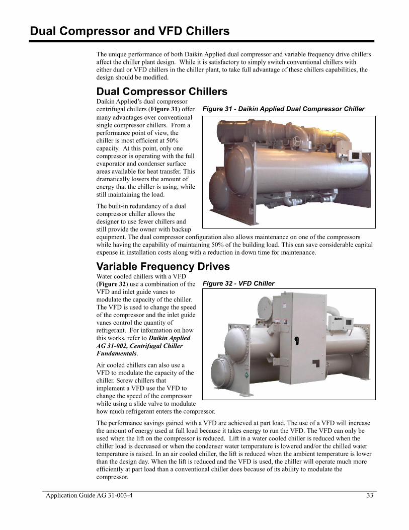
Application Guide AG 31-003-4 33
Dual Compressor and VFD Chillers
The unique performance of both Daikin Applied dual compressor and variable frequency drive chillers
affect the chiller plant design. While it is satisfactory to simply switch conventional chillers with
either dual or VFD chillers in the chiller plant, to take full advantage of these chillers capabilities, the
design should be modified.
Dual Compressor Chillers Daikin Applied’s dual compressor
centrifugal chillers (Figure 31) offer
many advantages over conventional
single compressor chillers. From a
performance point of view, the
chiller is most efficient at 50%
capacity. At this point, only one
compressor is operating with the full
evaporator and condenser surface
areas available for heat transfer. This
dramatically lowers the amount of
energy that the chiller is using, while
still maintaining the load.
The built-in redundancy of a dual
compressor chiller allows the
designer to use fewer chillers and
still provide the owner with backup
equipment. The dual compressor configuration also allows maintenance on one of the compressors
while having the capability of maintaining 50% of the building load. This can save considerable capital
expense in installation costs along with a reduction in down time for maintenance.
Variable Frequency Drives Water cooled chillers with a VFD
(Figure 32) use a combination of the
VFD and inlet guide vanes to
modulate the capacity of the chiller.
The VFD is used to change the speed
of the compressor and the inlet guide
vanes control the quantity of
refrigerant. For information on how
this works, refer to Daikin Applied
AG 31-002, Centrifugal Chiller
Fundamentals.
Air cooled chillers can also use a
VFD to modulate the capacity of the
chiller. Screw chillers that
implement a VFD use the VFD to
change the speed of the compressor
while using a slide valve to modulate
how much refrigerant enters the compressor.
The performance savings gained with a VFD are achieved at part load. The use of a VFD will increase
the amount of energy used at full load because it takes energy to run the VFD. The VFD can only be
used when the lift on the compressor is reduced. Lift in a water cooled chiller is reduced when the
chiller load is decreased or when the condenser water temperature is lowered and/or the chilled water
temperature is raised. In an air cooled chiller, the lift is reduced when the ambient temperature is lower
than the design day. When the lift is reduced and the VFD is used, the chiller will operate much more
efficiently at part load than a conventional chiller does because of its ability to modulate the
compressor.
Figure 31 - Daikin Applied Dual Compressor Chiller
Figure 32 - VFD Chiller

34
Application Guide AG 31-003-4
The best way to take advantage
of a water cooled VFD chiller is to
reduce the condenser water
temperature as much as possible.
Climates with reasonable annual
changes in wet-bulb are prime
candidates for VFD chillers.
VFDs also provide benefits on
the electrical characteristics of the
unit. They provide lower starting
currents compared to the
traditional starters that are used, as
seen in Figure 33. This feature
can help to reduce the electrical
installation costs, especially if the
chiller is powered from
emergency generators. The lower
inrush current requirements
typically allow the owner to
downsize the capacity of the
emergency generator.
System Design Changes Conventional Application Both dual compressor and VFD chillers operate much more efficiently at part load. Conventional
chillers operate most efficiently at or near full load. To fully optimize a dual or VFD chiller, the design
should take advantage of their part load performance because a building spends the most operating
hours at part load conditions.
Figure 34 is based on two equally sized chillers in a primary/secondary arrangement using the AHRI
condenser relief profile for the entire plant. At the 50% load point, the second chiller must be started.
For conventional chillers, the chiller performance drops because the load is split evenly between the
two chillers and they unload to a less efficient operating point. The dual and VFD chillers actually
improve their performance because the chillers are unloaded and there is condenser relief available.
Figure 34 - Chiller Performance vs. Plant Load
Figure 33 - Comparison of Starter Inrushes

Application Guide AG 31-003-4 35
Considering that most buildings experience a significant number of operating hours around 50% plant
load, the dual or VFD chillers may offer appreciable savings even when used in a convention manner.
Lead Chiller Application The first chiller that is activated in a plant, typically called the lead chiller, operates with many hours at
reduced load and condenser water temperature. An example is a multi-chiller primary secondary plant.
The lead chiller sees optimal conditions for either a VFD or a dual compressor chiller. The other
chillers in the plant can be conventional chillers. Each chiller that is started as the plant load increases
will operate at a higher percent load with less condenser water relief and therefore will offer fewer
savings.
Winter Load Application Another good application for a dual or VFD chiller is winter load applications. Building using fan
coils have considerable chiller plant loads even in winter. Other buildings such as hospitals or office
buildings with computer, telecommunication, or other winter chilled water loads can also take
advantage of a dual or VFD chiller. In many cases, these winter loads are relatively small.
Conventional thinking would require a smaller chiller sized specifically for the load. With a dual or
VFD chiller, there may not be a performance penalty to use a larger chiller sized for summer loads to
handle the small winter load. The peripheral loads such as pumps should be checked when evaluating
performance.
Series Chiller Application A common method for sizing chillers used in series is to select both chillers to be able to perform as
the lead chiller. This causes the lag chiller to be sub-optimized because the lift is reduced in the lag
position. By using a VFD chiller as the upstream chiller, the VFD can take advantage of the reduced
lift when operating as the lag chiller. In addition, the same chiller can be used as the lead chiller during
light loads when there should be condenser water relief available.
Asymmetrical Chiller Application Selecting the chillers to be different sizes can improve chiller plant performance based on the building
load profile. Using either a dual or VFD chiller for that larger chiller can enhance the savings.
Consider a 1200-ton plant consisting of an 800-ton dual compressor and a 400-ton single compressor
chiller. The dual compressor chiller can accommodate the plant load up to 800 tons. Above that, the
second chiller must be started and both chillers will initially operate at 67%. The larger chiller will be
more efficient when unloaded.
Low Delta T Application Most variable flow chiller plants will see a drop in return water temperature as the load drops. The low
delta T can cause serious operation issues with the plant. One solution is to use either dual or VFD
chillers and operate two chillers at part load as opposed to one chiller fully loaded. The dual or VFD
chillers partly loaded should be more efficient than one conventional chiller fully loaded. The chiller
savings can be used to offset the additional pumping cost from operating peripheral pumps. Moreover,
this arrangement will provide the necessary chilled water flow on the primary side to offset the low
delta T problem.
Total System Analysis When estimating the savings, consider both the type of chillers used and the available lift reduction
(condenser relief) and peripheral equipment that must be operated. Simulations can be run to determine
the best possible solutions.

36
Application Guide AG 31-003-4
Mechanical Room Safety
Chillers represent large, powerful machines filled with refrigerants. When chillers are placed in
confined spaces, care must be exercised to provide safety to the equipment operator and the public at
large.
ASHRAE Standard 15, Safety Standard for Refrigeration Systems and ASHRAE Standard 34,
Designation and Safety Classification of Refrigerants, provides the designer with an excellent
reference when designing a chiller mechanical room. In Canada, CSA–B52, provides similar
information.
The following is a brief summary of the safety
requirements covered by these documents as they apply
to chiller mechanical rooms. This section is by no means
a complete review of all requirements covered by these
standards. It is recommended that the design have
access to the most recent version of these documents. It
is also recommended to be familiar with local safety
codes that have jurisdiction in the area of construction.
Standard 15 The purpose of Standard 15 is to specify “safe design,
construction, installation, and operation of refrigeration
systems .” The following is a brief outline of the issues
that affect chiller mechanical room design.
Occupancy Classification Standard 15
6 identifies seven occupancy types that
consider the ability of the occupants to respond to a
potential exposure to refrigerant. An example is
Institutional Occupancy where it is anticipated that the
occupants may be disabled and not capable of readily leaving the building without assistance. A
hospital is an institutional building.
Refrigeration System Classification Refrigeration systems are based on how they extract or deliver heat. Chiller plants are considered
indirect systems because they cool chilled water, which in turn cools the air. Indirect systems are
subsequently subdivided by how the secondary fluid (chilled water) contacts the air stream. Assuming
coils are used, the classification is indirect closed system. If open spray coil systems are used then the
classification becomes either indirect open spray system or double indirect spray system.
The refrigeration system classification is used to determine the probability that a refrigeration leak
would enter the occupied space. Indirect closed systems such as chiller plants are generally considered
Low-Probability systems provided they are either outside the building or in a mechanical room.
Refrigeration Safety Classification Standard 15 uses the safety classifications listed in Standard 34. Table 4 of this guide is based on Table
1 from Standard 15. It shows the group, refrigerant name, formula and the minimum quantity of
refrigerant allowed in an occupied area. Blends such as R-407C and R-410a are classified based on the
worst case fractionation of the refrigerant.
6 ASHRAE, 2010. ANSI/ASHRAE Standard 15-2010, Safety Standard for Refrigeration Systems.
Atlanta, Ga.: ASHRAE

Application Guide AG 31-003-4 37
Table 4 - Standard 15 Refrigerants and Amounts7
Refrigerant
ASHRAE
Standard 34
Safety
Classification
Occupational
Exposure
Limit (OEL)
ppm
Refrigeration
Concentration
Limit (RCL)
lb/100ft3
R-11 A1 1000 0.39
R-12 A1 1000 5.60
R-22 A1 1000 13.00
R-32 A2L 1000 4.80
R-123 B1 50 3.50
R-134a A1 1000 13.00
R-290 (Propane) A3 1000 0.56
R-245 fa B1 300 12.00
R-600 (Butane) A3 1000 -
R-717 (Ammonia) B2L 25 0.01
R-744 (CO2) A1 5000 4.50
R-1234 yf A2L 500 4.70
R-404A A1 1000 31.00
R-407C A1 1000 17.00
R-410A A1 1000 25.00
R-500 A1 1000 7.60
Restrictions on Refrigeration Use The restrictions on where refrigerants can be used are based on results of occupancy, refrigerant system
type and refrigeration type. With a high probability system (the refrigerant can enter the occupied
space i.e. a VRV system) the maximum refrigerant level is defined in Standard 15. For example R-
123 can only have a concentration of 0.4 lb per 1000 ft³ occupied space. Once these levels are
exceeded, the refrigeration equipment must be either outdoors or in a mechanical room. Refrigerant
levels involved in chiller plants necessitate mechanical rooms or outdoor equipment.
An interesting issue occurs when an air handling unit that serves occupied spaces is in the chiller
mechanical room. If a leak occurs, the refrigerant may be drawn into the air handling unit and
circulated through the building. The best solution to this is to avoid air handling units in the chiller
mechanical room. This may not be possible in existing buildings. Standard 15 does allow AHUs in
the chiller mechanical room if they are sealed.
Pressure Relief Piping One area that will involve the designer is pressure relief devices and piping. The pressure relief
devices are typically part of the chiller. With field refrigerant piping, additional relief devices may be
required. Medium to high pressure refrigeration systems typically use re-seating spring loaded
pressure relief valves. Negative pressure chillers often use rupture disks. Rupture disks are less
expensive however, if they burst, the entire charge will be lost. Spring loaded pressure relief valves
will re-seat as soon as the pressure within the refrigeration system drops to safe level. For negative
7 ASHRAE, 2010. ANSI/ASHRAE Standard 34-2010, Designation and Safety Classification of
Refrigerants. Atlanta, Ga.: ASHRAE. This standard is under continuous maintenance, so its contents
change regularly.

38
Application Guide AG 31-003-4
pressure chillers, it is recommended that reseating pressure relief valves be used in addition to rupture
disks for additional protection.
Pressure relief devices and purge unit discharges must be piped to the outdoors. The location must not
be less than 15 ft above grade or 20 ft from a window, ventilation opening or doorway and the line size
shall be at least the discharge size of the pressure relief device or fusible plug.
Multiple relief devices can be connected to a common header. The header size must be at least the sum
of the discharge areas of the connected devices and designed to accommodate the pressure drop. Many
chiller application catalogs provide tables for sizing relief piping.
ASHRAE Standard 15 also includes tables for sizing relief piping. The size of the relief piping is
dependent upon the length of the pipe between the pressure relief device and the outdoors. Appendix H
of Standard 15 provides equations to determine the allowable length of piping as a function of its
diameter.
The allowable equivalent length of relief piping is determined from the following equation:
𝐿 =0.2146 𝑑 (𝑃
− 𝑃 )
𝑓𝐶
−𝑑 𝑙𝑛(
𝑃 𝑃 )
6𝑓
Where:
L = equivalent length of discharge piping, ft
Cr = rated capacity as stamped on the relief device in lb/min, or in SCFM multiplied by
0.0764, or as otherwise calculated
f = Moody friction factor in fully turbulent flow8
d = inside diameter of pipe, in
P2 = absolute pressure at outlet of discharge piping, psi
P0 = absolute pressure allowed at the outlet of the pressure relief device, psi
Standard 34 Standard 34 lists refrigerants and provides a safety classification as shown in Figure 35
9. Refer to
Standard 34 or to Daikin Applied Application Guide AG 31-007, Refrigerants for further information
on common refrigerants and their safety properties.
8 Moody friction factors are available in ASHRAE Standard 15 and in Moody, L.F. (1944) “Friction
factors for pipe flow”, Transactions of the ASME 66(8):671-684.
9 ASHRAE, 2010. ANSI/ASHRAE Standard 34-2010, Designation and Safety Classification of
Refrigerants. Atlanta, Ga.: ASHRAE
*A2L and B2L are lower flammability refrigerants with a
maximum burning velocity of < = 10 cm/s (3.9 in/s)
Lower
Toxicity
Higher
Toxicity
Higher
Flammability A3 B3
A2 B2
A2L* B2L*No Flame
Propagation A1 B1
Lower
Flammability
Figure 35 - ASHRAE Standard 34 Safety Classification

Application Guide AG 31-003-4 39
Single Chiller System
Single chiller systems are the easiest to design and operate but are also the least efficient chiller plant
design for buildings. Moreover, they provide no redundancy; if the chiller fails, all cooling is lost.
Single chiller plants require the smallest mechanical room, particularly if the chiller is air or
evaporatively cooled. Water cooled or air cooled chillers can be used however, air cooled chillers do
not require a condenser loop including piping, cooling tower, and pump.
Basic Operation Figure 36 shows a single water-cooled chiller plant with constant flow and 80% cooling load diversity.
Chilled water is circulated by the chilled water or primary pump through the chiller to the load and
back to the chiller. The chilled
water loop can be either
constant flow or variable flow.
Variable flow systems increase
the complexity but offer
significant pump work
savings. Variable flow
systems are covered in
Primary Secondary Systems and Variable Primary Flow
Design. A condenser loop is
required for water cooled
chillers. This includes a
condenser pump, piping, and a
cooling tower or closed circuit
cooler. The condenser loop
operates whenever the chiller
operates.
For constant flow systems, the
chilled water temperature
range varies directly with the load. Depending on the load diversity, the chiller design temperature
range will be less than the range seen at each load. In this case, the chiller range is 8°F while the
cooling coil range is 10°F (Refer to the section on Piping Diversity). The overall result is increased
chilled water pump and pipe capital cost plus higher annual pumping cost.
Basic Components Chillers The chiller is sized to meet the design load of the building or process. For building loads, the chiller
only operates at full capacity for approximately 2% of the year. This means that for the rest of the
year, the chiller is running at part load or turned off. Single chiller plant design can be used effectively
if the chiller is chosen with an efficient full efficiency and an even more efficient part load efficiency.
In addition to this, the dual compressor chiller design will also capitalize on the part load efficiencies,
saving in operating costs throughout the year. Again the dual compressor chillers can offer complete
redundancy of all major mechanical components, which resolves another issue with single chiller plant
design.
Pumps Pumps can be constant or variable flow. Pump basics are covered in the section on Pumping Basics.
Both the chilled water and condenser pump must be sized for the design flow rates. Whenever the
chiller operates, these pumps will operate. If the chiller has a VFD, then the pumps should likewise
have the ability to throttle down the flow to maintain the minimum flow requirements of the chiller.
The result is that the design chilled water and condenser flow are being pumped any time the chiller
plant is operating.
Figure 36 - Basic Single Chiller System Operation

40
Application Guide AG 31-003-4
Cooling Towers Water cooled chiller systems will require cooling towers. Cooling towers and operation are covered in
Cooling Tower Basics.
Single Chiller Sequence of Operation Single chiller plants are the most straightforward to operate. Recognizing the need for chilled water is
the first goal. This can be as simple as manually enabling the chiller. The process can be automated
with a building automation system (BAS) which can recognize when mechanical cooling is required.
All chillers must have chilled water
(and condenser water, if appropriate)
flow before they operate. The
simplest method is to manually turn
on the pumps prior to enabling the
chiller. The chiller controller, in many
cases, includes a signal to operate the
chilled and condenser water pumps.
In this case, the pump starters can be interlocked with the chiller control panel to start the pumps.
Pumps should shut down when not required to save energy. To ensure proper operation of the chiller,
the pumps will be turned on, and flow will be ensured before the compressor on the chiller turns on.
Variable flow systems add another degree of complexity but also provide significant pump work
savings. Control sequences for variable flow systems are covered in other sections of this guide.
In addition to operating the pumps, it is necessary to prove that there is flow. Pressure differential or
paddle type switches can be used and usually are connected directly to the chiller controller. Current
☺Tip: Chillers are not technically started, they are
enabled. The difference is subtle but important.
Enabling a chiller means the chiller is allowed to
operate if it needs to. For instance, if there is no load,
the chiller will not start even though it has been enabled.
If you were truly starting the chiller, the compressor
would start as soon as you threw the switch.
Single Chiller Plant Example Consider a model 7-story office building in Minneapolis with 375,000 ft². The air conditioning
system is floor-by-floor VAV with reheat and a single chiller plant as shown in Figure 36.
Reviewing the design performance does not indicate how well the system will operate annually.
The annual kWh/yr usage tells a different story. Although pumps are much smaller than the
chiller, they end up using almost two-thirds the energy that the chiller uses. This happens
because the chilled water and condenser pumps must operate at plant design flow rates any time
there is a requirement for chilled water.
Although fans are not part of the chiller plant, it is important to notice that they too consume a
significant amount of power over the course of a year. In this case, more energy is used
operating the fans than the chiller. This is a direct result of where the building is located. If you
were to move the building to San Juan, for example, the amount of energy used by the chiller
plant would out weight that of the fan energy.

Application Guide AG 31-003-4 41
sensing devices can also be used. Operating a chiller without flow can result in serious damage. It is
recommended that the manufacturer’s installation instructions be followed carefully to provide proper
operation and avoid warranty conflicts.
Systems requiring a cooling tower will need to control it. Sequences for cooling towers are covered in
detail in Cooling Tower Basics. Additional information on chiller plant controls can be found in
product catalogs, as well as in installation and maintenance manuals.

42
Application Guide AG 31-003-4
Parallel Chiller System
To provide some redundancy in the HVAC design, most designers will require two or more chillers.
Multiple chillers also offer the opportunity to improve on overall system part load performance and
reduce energy consumption. Parallel chiller plants are straightforward to design and are easily
modified for variable primary flow.
Basic Operation Figure 37 shows a parallel water cooled chiller plant. Chilled water is circulated by the chilled water
or primary pump through both chillers to the load and back to the chillers. The chilled water loop can
be either constant flow or variable flow. Variable flow systems increase the complexity but offer
significant pump work savings. They also resolve the issue about chiller sequencing that occurs with
parallel chillers, constant flow.
Variable flow systems are
covered in Primary
Secondary Systems and
Variable Primary Flow
Design.
For constant flow systems, the
chilled water temperature
range varies directly with the
load. Depending on load
diversity, the chiller design
temperature range will be less
than the temperature range
seen at each load. In this case,
the chiller temperature range
is 8°F while the cooling coil
range is 10°F (Refer to Piping
Diversity). The overall result
is increased chilled water
pump and pipe capital cost
plus higher annual pumping
cost.
Basic Components Chillers In most cases, the sum of the chiller
capacities meets the design for the
building or process. Additional
capacity can be added, if required,
by over sizing the chillers. It is
common for parallel chillers to be
the same size and type although this
not a requirement. Water cooled, air
cooled, or evaporatively cooled
chillers can be used. Air and
evaporatively cooled chillers do not require a condenser loop including piping, cooling tower, and
pump.
Figure 37 - Basic Parallel Chiller System Operation
☺Tip: Parallel chillers, in a constant flow system, experience
the same percent load. For example, consider a chiller plant
with a 100-ton and a 1000-ton chiller operating at 50%
capacity. With both chillers operating, both chillers will
operate at 50% capacity. The 100-ton chiller will be at 50
tons and the 1000-ton chiller will be at 500 tons. This occurs
as long as the flows don’t change (i.e,. variable primary flow)
and both chillers see the same return water temperature.

Application Guide AG 31-003-4 43
Pumps Pumps can be constant or variable flow. Pump basics are covered in Pumping Basics. The chilled
water pump is sized for the design flow rate. Figure 38 shows dedicated chilled water pumps, each
providing flow to their own chiller. An alternative method is to have one large pump that serves both
chillers. The pumps and piping are sized for the design condenser flow for each chiller. Whenever the
chiller operates, the condenser pump operates. With the configuration shown in Figure 38, it can be
seen that if you were at 50% load, you would only need to run one condenser and one evaporator
pump, not all four.
Cooling Towers Water cooled chillers will require cooling towers. A common cooling tower is also possible but not
recommended for parallel chillers. Cooling towers are covered in Cooling Tower Basics.
Parallel Chiller Sequence of Operation Parallel chiller plants create a unique situation when used in a constant flow system. Consider a two
chiller system operating at less than 50% of total plant load. From a chiller performance aspect,
turning off one chiller and operating the other at a higher capacity may be desirable if the running
chiller will operate at its peak efficiency. However, this will not happen if the idle chiller is not
isolated from the water loop. For example at 50% capacity, the return water will be 49°F in a typical
AHRI plant of ten degree chilled water range. The chiller that is turned off will let the water pass
through it unchanged. The operating chiller will only see a 50% load (49°F return water), and will
cool the water down to the set point of 44°F. The two chilled water streams will then mix to 46.5°F
supply temperature.
If the system is operated in this manner, the warmer chilled water will cause the control valves to open
(increase flow) to meet the space requirements. An iterative process will occur and the system may
stabilize. The issue is whether the cooling coils can meet the local loads with the higher chilled water
temperature. Depending on the actual design conditions, the building sensible load could be met but
high chilled water temperature will make it difficult to meet the latent load. Since this scenario is
likely to occur during intermediate weather, dehumidification may not be an issue. In areas where
humidity is an issue, this arrangement can result in high humidity within the space.
One solution is to operate both chillers all the time. This works and is a simple solution; however, it
may not be energy efficient and causes avoidable equipment wear.
Another possibility is to lower the operating chiller’s set point to offset the mixed water temperature.
This also works but has some difficulties. Lowering the chilled water setpoint requires the chiller to
work harder, lowering its efficiency. In extreme conditions, it can cause chiller stability issues.
ASHRAE Standard 90.1 requires that when a parallel chiller is shut down, the total plant flow rate
must be reduced accordingly. This is most often done in constant flow systems by stopping chilled
water pumps and isolating any chillers that are not operating with automatic control valves. With
reduced flow, all the cooling coil control valves will adjust to maintain their design setpoint. Standard
Figure 38 - Typical Parallel Chiller System
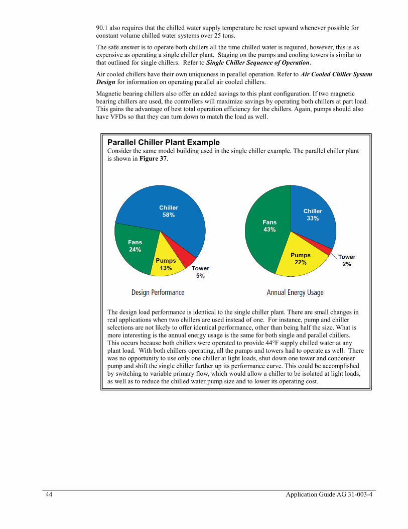
44
Application Guide AG 31-003-4
90.1 also requires that the chilled water supply temperature be reset upward whenever possible for
constant volume chilled water systems over 25 tons.
The safe answer is to operate both chillers all the time chilled water is required, however, this is as
expensive as operating a single chiller plant. Staging on the pumps and cooling towers is similar to
that outlined for single chillers. Refer to Single Chiller Sequence of Operation.
Air cooled chillers have their own uniqueness in parallel operation. Refer to Air Cooled Chiller System
Design for information on operating parallel air cooled chillers.
Magnetic bearing chillers also offer an added savings to this plant configuration. If two magnetic
bearing chillers are used, the controllers will maximize savings by operating both chillers at part load.
This gains the advantage of best total operation efficiency for the chillers. Again, pumps should also
have VFDs so that they can turn down to match the load as well.
Parallel Chiller Plant Example Consider the same model building used in the single chiller example. The parallel chiller plant
is shown in Figure 37.
The design load performance is identical to the single chiller plant. There are small changes in
real applications when two chillers are used instead of one. For instance, pump and chiller
selections are not likely to offer identical performance, other than being half the size. What is
more interesting is the annual energy usage is the same for both single and parallel chillers.
This occurs because both chillers were operated to provide 44°F supply chilled water at any
plant load. With both chillers operating, all the pumps and towers had to operate as well. There
was no opportunity to use only one chiller at light loads, shut down one tower and condenser
pump and shift the single chiller further up its performance curve. This could be accomplished
by switching to variable primary flow, which would allow a chiller to be isolated at light loads,
as well as to reduce the chilled water pump size and to lower its operating cost.

Application Guide AG 31-003-4 45
Series Chillers
Series chillers are another method of operating more than one chiller in a plant. This design concept
resolves the mixed flow issues found in parallel chiller designs. The chillers can be preferentially
loaded as well, allowing the designer to optimize chiller performance. Series chiller systems are
straightforward to design and operate.
Basic Operation Figure 39 shows two chillers in series. All the system flow goes through both chillers. As a result, the
water pressure drops through the evaporators are additive. The chilled water loop can be either
constant or variable flow. Variable flow systems increase the complexity but offer significant pump
savings. A condenser loop is required for water cooled chillers. This includes a condenser pump,
piping, and a cooling tower or
closed circuit cooler. The
condenser loop operates whenever
the chillers operate.
If both chillers are the same and the
condensers are piped in parallel, the
lead chiller will accomplish about
45% of the system load and the lag
chiller will accomplish about 55%
of the system load. This occurs
because the lead (downstream)
chiller is supplying chiller water at
the system set point (typically
44°F). The lag (upstream) chiller is
supplying chilled water at
approximately 48.5°F to the lead
chiller. The reduced lift for the lag
chiller allows it to provide more
cooling capacity.
For constant flow systems, the
chilled water temperature range
varies directly with the load. Depending on the load diversity, the chiller design temperature range will
be less than the range seen at each load. In this case, the chiller range is 8°F while the cooling coil
range is 10°F (Refer to Piping Diversity, page 25). The overall result is an increased chilled water
pump and pipe capital cost plus higher annual pumping cost.
A problem with series chillers is the high flow rate and the low temperature range through the chillers.
The high flow rate can result in high water pressure drops. Since the chillers are in series, the pressure
drops of the chillers must be added. If the typical 10°F system temperature difference is maintained,
then single pass evaporators should be considered. This will lower the pressure drop to an acceptable
level.
Basic Components Chillers Chillers selected for series applications require special consideration. Special care should be taken
when using smaller chillers with limited shell arrangements such as small air or water cooled chillers.
The pressure drops are typically designed to be acceptable with the flow rates around 2.4 USgpm/ton.
When the flow is increased to
4.8 USgpm/ton as in series
applications, the pressure drop
rises significantly. A 10 ft
pressure drop at 2.4
USgpm/ton will be a 40ft
pressure drop at 4.8
☺Tip: For series chillers, the evaporator pressure drops must be
added. Care should be taken when using chillers with limited shell
arrangements such as small air or water-cooled products. The
pressure drops (at the correct flow rate) can be very high. For
larger chillers with flexible shell arrangements, consider single
pass to reduce the water pressure drops.
Figure 39 - Basic Series Chiller System Operation

46
Application Guide AG 31-003-4
USgpm/ton. With larger chillers that offer flexible shell arrangements, single pass shells can be used to
lower the pressure drop. Two single pass shells in series will be comparable to a typical two-pass shell
in water pressure drop.
The chillers will not see the same duty; the lead chiller has a different lift requirement than the lag
chiller. The more difficult duty is the lead chiller. The selections must be done so that the chillers
operating at the specific conditions will provide the required capacity. The actual chiller output and
performance will most likely be different. Selecting both chillers to be the same machine and able to
meet the requirements of the lead position allows the chillers to be interchangeable when the plant load
is less than one chiller’s capacity. There is some performance loss when the chiller is operated in the
lag position because the chiller is not optimized for that specific lift. It is possible to select two
different chillers, each optimized for their operating conditions. This arrangement will be slightly
(about 2%) more efficient but the chillers will not be interchangeable.
Increasing the chilled water
temperature range affects series
chillers differently than parallel
chillers. As the range is
increased, series chillers will
generally outperform parallel
chiller arrangement. This occurs because the cascading effect of series chillers enhances the chillers’
performance.
Pumps Pumps can be constant or variable flow. Pump basics are covered in Pumping Basics. The chilled
water pump is sized for the design flow rate. The chilled water design head will be impacted by
having to add the chiller pressure drops together. Figure 40 shows a variable primary chilled water
pumping configuration. These pumps provide redundancy along with the ability to vary the flow
through the series of
chillers. Each chiller also
has its own cooling tower
and pump. The pumps and
piping are sized for the
design condenser flow for
each chiller. Whenever
the chiller operates, the
condenser pump operates.
Cooling Towers Water cooled chillers will
require cooling towers.
Figure 40 shows
dedicated cooling towers
for each chiller. A
common cooling tower is
also possible but not
common for series
chillers. Cooling towers
are covered in Cooling
Tower Basics.
Series Chillers Sequence of Operation Series chillers can be preferentially loaded. As the chiller plant load increases, the lead (downstream)
chiller will load from 0 to 100% capacity to meet it. Once the lead chiller is loaded (which is likely to
be about 45% of plant capacity) the lag chiller is started. Here are three ways to operate the lag chiller:
1. Set the upstream chiller chilled water setpoint to bring on the chiller once the downstream
chiller is fully loaded. For example, if the downstream chiller is fully loaded when it receives
full water flow and an eight degree temperature difference, the upstream chiller’s discharge
temperature should be set to the plant design temperature plus the eight degrees (i.e. 44°+8° =
52°). This will preferentially load the downstream chiller. The downstream chiller will
☺Tip: Series chillers operate more effectively at increased chilled
water temperature ranges than parallel chillers. As the chilled
water range is increased, you can expect series chiller
arrangements to outperform parallel chiller arrangements.
Figure 40 - Typical Series Chiller System

Application Guide AG 31-003-4 47
operate at full load while the upstream chiller will ramp up as the chiller plant load goes from
about 45% to 100%. If the downstream chiller is offline for any reason, the upstream chiller
will not be able to assume its role unless the chilled water setpoint is changed, either manually
or remotely.
2. Move the upstream chiller sensor downstream of both chillers. This will preferentially load
the upstream chiller. Once the upstream chiller cannot maintain the chilled water supply
temperature, the downstream chiller will start and provide the balance of the load.
3. Modern chiller controllers can allow two or more chillers to communicate. In this
arrangement. Either chiller can be the first chiller on, assuming they were both selected to do
the lead chiller duty. Once the first chiller is fully loaded, the second chiller will start and the
load will be evenly balanced between the two chillers. This can result in about a 2%
improvement in annual chiller energy usage. Where possible, this method is recommended.
Staging on the pumps and cooling towers is similar to that outlined for single chillers. Refer to Single
Chiller Sequence of Operation.
Series Chiller Plant Example Consider the same model building used in the single chiller example. The series chiller plant is
shown in Figure 40Error! Reference source not found..
The design load performance is identical to the single or parallel chiller systems. In this case, it
has been assumed that the sum of the chiller pressure drops for series chillers equals the
pressure drops through single or parallel two-pass chillers. In most cases, the pressure drop
will be higher for series systems.
As before, air system fans are the dominant HVAC load when reviewing annual energy usage.
Series chillers provide some savings over constant flow parallel and single chiller systems. In
variable primary flow systems, parallel chillers would typically slightly outperform series
chillers at AHRI conditions. As the chilled water temperature range is increased, series chillers
would again outperform parallel chillers.

48
Application Guide AG 31-003-4
Constant Flow Series Counterflow Chillers Series counterflow chillers are shown in Figure 41. This arrangement differs from the series chillers
system shown in Figure 40 in that the condenser flow passes through both chillers in series,
counterflow to the chilled water. Series counterflow condenser water improves the chiller performance
as explained in the series counterflow chiller example.
Series counter flow chillers can be
5 to 7% more efficient than a single
chiller at design conditions and
save up to 20% of chiller energy
annually. However, the condenser
pump is sized for the entire system
flow (in this case 2400 US gpm)
and this pump must operate
whenever any chiller operates. The
result is increased pump work
annually. Series chillers with
parallel towers may outperform
series counterflow chillers
depending on the chiller savings
versus pump losses. Where series
counterflow chillers can be
advantageous is in large primary
secondary chiller plant systems.
Figure 41 - Series Counterflow System Design

Application Guide AG 31-003-4 49
Using VFD Chillers in Series Arrangements A common practice in selecting chillers for series applications is to select both chillers to be the same
and meet the most demanding lift. For centrifugal chillers, this means the compressors are selected for
the largest lift on a design day. The chiller that is then used as the lag chiller provides too much lift
and is not optimized. A solution to this is to use a centrifugal chiller with a VFD as the upstream
chiller. This has two advantages:
1. During periods when the chiller plant load is less than 45% (about the limit for one chiller) the
VFD chiller can be used and take advantage of any condenser relief available. Considering this is a
part load situation, condenser relief should be significant.
2. When two chillers are required, the VFD chiller can use the VFD to optimize its performance
while being used in the lower lift application.
Both chillers do not need to have VFDs. Either chiller will work in either application (lead or lag)
without a VFD.
Series Counterflow Plant Example
Consider the same model building used in the single chiller example. The series counterflow
chiller system is shown in Figure 41.
The series counterflow arrangement has improved the chiller performance as described in the
sidebar. This has resulted in an overall design condition performance improvement.
As expected, the annual chiller work went down because of the enhanced chiller performance.
On the other hand, the large condenser pump (sized for the design condenser flow) which must
operate whenever there is a need for chilled water, has increased the annual pump work.
Whether series counterflow will save energy on an annual basis will depend on the pump
penalty vs. the chiller savings.
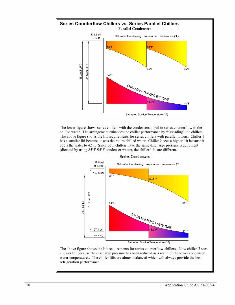
50
Application Guide AG 31-003-4
Series Counterflow Chillers vs. Series Parallel Chillers Parallel Condensers
The lower figure shows series chillers with the condensers piped in series counterflow to the
chilled water. The arrangement enhances the chiller performance by “cascading” the chillers.
The above figure shows the lift requirements for series chillers with parallel towers. Chiller 1
has a smaller lift because it sees the return chilled water. Chiller 2 sees a higher lift because it
cools the water to 42°F. Since both chillers have the same discharge pressure requirement
(dictated by using 85°F-95°F condenser water), the chiller lifts are different.
Series Condensers
The above figure shows the lift requirements for series counterflow chillers. Now chiller-2 sees
a lower lift because the discharge pressure has been reduced as a result of the lower condenser
water temperatures. The chiller lifts are almost balanced which will always provide the best
refrigeration performance.
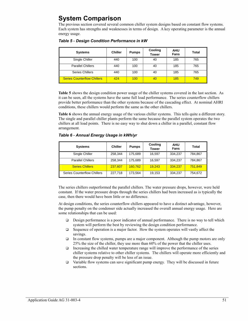
Application Guide AG 31-003-4 51
System Comparison The previous section covered several common chiller system designs based on constant flow systems.
Each system has strengths and weaknesses in terms of design. A key operating parameter is the annual
energy usage.
Table 5 - Design Condition Performance in kW
Systems Chiller Pumps Cooling
Tower
AHU Fans
Total
Single Chiller 440 100 40 185 765
Parallel Chillers 440 100 40 185 765
Series Chillers 440 100 40 185 765
Series Counterflow Chillers 424 100 40 185 749
Table 5 shows the design condition power usage of the chiller systems covered in the last section. As
it can be seen, all the systems have the same full load performance. The series counterflow chillers
provide better performance than the other systems because of the cascading effect. At nominal AHRI
conditions, these chillers would perform the same as the other chillers.
Table 6 shows the annual energy usage of the various chiller systems. This tells quite a different story.
The single and parallel chiller plants perform the same because the parallel system operates the two
chillers at all load points. There is no easy way to shut down a chiller in a parallel, constant flow
arrangement.
Table 6 - Annual Energy Usage in kWh/yr
Systems Chiller Pumps Cooling
Tower
AHU Fans
Total
Single Chiller 258,344 175,689 16,597 334,237 784,867
Parallel Chillers 258,344 175,689 16,597 334,237 784,867
Series Chillers 237,607 160,762 19,243 334,237 751,849
Series Counterflow Chillers 227,718 173,564 19,153 334,237 754,672
The series chillers outperformed the parallel chillers. The water pressure drops, however, were held
constant. If the water pressure drops through the series chillers had been increased as is typically the
case, then there would have been little or no difference.
At design conditions, the series counterflow chillers appeared to have a distinct advantage, however,
the pump penalty on the condenser side actually increased the overall annual energy usage. Here are
some relationships that can be used:
Design performance is a poor indicator of annual performance. There is no way to tell which
system will perform the best by reviewing the design condition performance.
Sequence of operation is a major factor. How the system operates will vastly affect the
savings.
In constant flow systems, pumps are a major component. Although the pump motors are only
25% the size of the chiller, they use more than 60% of the power that the chiller uses.
Increasing the chilled water temperature range will improve the performance of the series
chiller systems relative to other chiller systems. The chillers will operate more efficiently and
the pressure drop penalty will be less of an issue.
Variable flow systems can save significant pump energy. They will be discussed in future
sections.

52
Application Guide AG 31-003-4
Primary Secondary Systems
For large chillers or where more than two chillers are anticipated a primary secondary (also called
decoupled) piping system is often used. To reduce installation and operating costs, it is desirable to
apply diversity to the system flow. With diversity applied to flow, the pumps and piping will be
smaller. To accomplish this, two-way control valves are used at the loads. At the same time it is
desirable to provide constant flow through the chillers to maintain chiller stability. The solution is
primary secondary piping.
Basic Operation Figure 42 shows a 400 ton primary secondary system with four chillers. The system is operating at
67% or 268 tons. The 268 ton load requires 643 USgpm (10 USgpm/ton). Three chillers are operating
along with their 240 USgpm primary pumps.
The additional flow, 77 USgpm, from the three primary pumps bypasses the building through the
decoupler. The bypassed water mixes with the return water from the building and is returned to the
chillers. The chillers operate at the same percent load.
Basic Components Chillers Figure 42 also shows a typical primary secondary chiller plant with four chillers. There can be any
number, size, and type of chillers in the system. Different capacity chillers are acceptable and can be
advantageous depending on the
load profile. The only
requirement is that all chillers
must operate on the same chilled
water temperature range. Unless
specially configured, all
operating chillers will have the
same percent load.
Primary Pumps Primary pumps provide constant flow through the chillers. They can be dedicated to each chiller as
shown or there can be a primary pumping plant providing constant flow to each chiller. Primary
Figure 42 - Basic Primary/Secondary System Operation (67% Load)
☺Tip: All operating chillers in a primary-secondary plant see the
same percent load. For example, consider a plant consisting of one
100-ton chiller and one 1000-ton chiller operating at 50% load. In
this case, the 100-ton chiller will operate at 50 tons and the 1000-
ton chiller at 500 tons. Preferentially loading or back loading
chillers is possible, see Decoupler.

Application Guide AG 31-003-4 53
pumps can utilize a common header (See Figure 43) to allow a particular pump to serve several
chillers. The advantage is should a pump fail, the chiller can still be used by activating one of the other
pumps. A spare pump can also be built into the arrangement. The disadvantage to headered primary
pumps is complexity and cost.
If the chillers have different flow requirements, meaning they are different sizes, then intermixing
pumps becomes even more complicated. It can be done using VFDs on the pumps. The BAS can be
preprogrammed with the appropriate pump speed required to deliver the correct flow to each chiller.
This allows each chiller to receive its correct flow rate.
The flow for each chiller is based on the design flow required by the chiller. The flow is only provided
when the chiller is operating. An automatic isolating valve is required for each chiller to stop short-
circuiting when the chiller and pump are off.
Primary pumps need only provide enough head to move chilled water through the chiller and the
piping pressure drops between the chiller and the secondary pumps. Pump head values in the range of
25 to 75 ft are common.
Condenser Pumps If the chillers are water cooled, each chiller will have a condenser pump and cooling tower or other
form of heat rejection device. Like the primary pumps, the condenser pumps can be dedicated to each
chiller as shown or a condenser water pump plant can provide condenser flow. The flow rate to each
chiller is typically constant and based on the design flow rate for the chiller. Where the head pressure
drop is particularly high, variable flow condenser pumps may offer additional savings and are
becoming more common in chiller plant design.
Cooling Towers Cooling towers can be grouped or individual. Individual towers allow the tower to be sized
specifically for the chillers needs, which can be important in hybrid chiller plants. Cooling towers are
covered in Cooling Tower Basics.
Secondary Pumps Secondary pumps are variable flow and sized to provide flow throughout the chilled water plant. In a
sense, they handle all the pressure drops “outside the mechanical room”. Refer to Variable Flow
Pumps on how to vary the flow through pumps.
Figure 43 - Alternative Primary Pump Arrangement
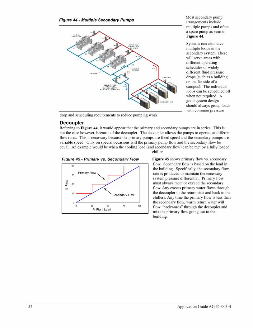
54
Application Guide AG 31-003-4
Most secondary pump
arrangements include
multiple pumps and often
a spare pump as seen in
Figure 44.
Systems can also have
multiple loops in the
secondary system. These
will serve areas with
different operating
schedules or widely
different fluid pressure
drops (such as a building
on the far side of a
campus). The individual
loops can be scheduled off
when not required. A
good system design
should always group loads
with common pressure
drop and scheduling requirements to reduce pumping work.
Decoupler Referring to Figure 44, it would appear that the primary and secondary pumps are in series. This is
not the case however, because of the decoupler. The decoupler allows the pumps to operate at different
flow rates. This is necessary because the primary pumps are fixed speed and the secondary pumps are
variable speed. Only on special occasions will the primary pump flow and the secondary flow be
equal. An example would be when the cooling load (and secondary flow) can be met by a fully loaded
chiller.
Figure 45 shows primary flow vs. secondary
flow. Secondary flow is based on the load in
the building. Specifically, the secondary flow
rate is produced to maintain the necessary
system pressure differential. Primary flow
must always meet or exceed the secondary
flow. Any excess primary water flows through
the decoupler to the return side and back to the
chillers. Any time the primary flow is less than
the secondary flow, warm return water will
flow “backwards” through the decoupler and
mix the primary flow going out to the
building.
Figure 44 - Multiple Secondary Pumps
Figure 45 - Primary vs. Secondary Flow

Application Guide AG 31-003-4 55
☺Tip: In situations where a new chiller is added to an older
existing chiller plant, relocating the decoupler can take full
advantage of the new chiller’s part load performance. Older
chiller may operate at 1 kW/ton or more at full load, worse at
part load. Relocating the decoupler allows the older chillers to
be base loaded (their best operating point) while the new chiller
is operated at part load. Consider either a VFD or dual
compressor chiller for additional savings.
Decoupler Sizing in Primary Secondary Loops Decouplers should be sized for the
flow rate of the largest primary pump.
This may be more than the design
flow rate of the largest chiller if
overpumping is being considered.
The pressure drop should not exceed
1.5 ft. As the pressure drop through
the decoupler increases, it tends to
make the primary and secondary
pumps behave like they are in series.
To avoid thermal contamination, the
decoupler should be at least three
pipe diameters in length. Longer
decouplers tend to increase the
pressure drop. When the secondary
return flows straight through in the
tee to the primary return, there should
be at least 10 pipe diameters to the
first chiller. This is to help avoid the possibility of having stratification in the primary return line,
which can lead to unmixed water to the first chiller. This can lead to chiller cycling.
Decoupler Location The location of the decoupler line
will change how the chillers are
loaded. Figure 46 shows the
typical layout with the decoupler
between the chillers and the load.
In this situation, each chiller sees
the same return water temperature
even at part load conditions.
Figure 47 shows the decoupler
line in a different location. Locating the chillers between the secondary loop and the decoupler line
causes the return water temperature to each chiller to vary. This is often referred to as “backloading”
or “preferentially” loading the chillers. Chiller 2 in Figure 47 will see close to the secondary loop
return water temperature. Chiller 1 will see a mixture of supply water and return water. As a result
chiller 2 is more heavily loaded than chiller 1.
Relocating the
decoupler can make
sense if one or more of
the chillers is a dual
compressor model or if
there is a VFD on the
compressor. These
types of chillers have
very good part load
performance. By
locating one of these
types of chillers close to
the decoupler line, and
the better full load
chiller furthest away, the
strengths of each chiller
can be maximized.
Another application for
backloading chillers is
Figure 46 - Decoupler Sizing
Figure 47 - Backloaded Primary Loop Layout

56
Application Guide AG 31-003-4
where one of the chillers is a heat recovery type, Daikin Applied’s Templifier™, is connected to the
condenser loop. In this case, providing additional load to that chiller provides a heat source for the
energy recovery process.
Decouplers should be sized for the maximum design chilled water flow through the largest chiller.
Their length should be as short as possible to minimize pressure drop.
System Expansion Primary/secondary piping allows easy expansion both in the chiller plant (primary loop) and the
building (secondary loop). To expand the chiller plant capacity, another chiller can be added to the
loop. By strategically locating the decoupler and the new chiller (see Figure 47), it is possible to apply
a greater load on the new chiller. This can be advantageous if the new chiller is more efficient than the
rest of the plant. If the building load is increased, a new loop can be added. The pump for the new loop
can be sized to meet the new loop’s pressure drop requirements.
Tertiary Pumping
There are two key applications where
tertiary piping is helpful. The first is
where the pressure available in the
secondary loop is not sufficient for a
specific load. The second is where a
load requires a different temperature
range than the main system.
Figure 48 shows a tertiary pumping
system. To localize pumps, a third
loop for the pumps is installed. The
tertiary pumps will handle all the head
requirements of the different towers.
This has the advantage that, if there is
a new load attached to the building,
the tertiary pumps can handle this new
load.
The arrangement in Figure 48
includes the tertiary pumps and two-
way control valves. The tertiary
pumps provide the necessary flow and
head for the facility it serves. If the
two-way valves begin to close, the
pumps will begin to slow down. The
secondary pumps will also be able to
be slowed down. The flow reduction
in the pumps will create savings in
energy for the system.
Another key advantage of this arrangement is the tertiary loop does not have to have the same
temperature range as the main loop. The design chilled water temperature in the tertiary loop must be
warmer than the main supply chilled water temperature. If they are the same temperature, the two-way
valve will open and bleed supply water into the
return line leading to low delta T syndrome
(See
Figure 48 - Tertiary Pumping
☺Tip: There are many instances where facilities
designed with different chilled water temperature
ranges are required to operate from a common
chilled water plant. This is a common occurrence
for large university and health care campuses.
Tertiary piping can be used to connect buildings
with different design temperature ranges and supply
water temperatures to a common plant.

Application Guide AG 31-003-4 57
Low Delta T Syndrome Causes and Solutions). The two-way valve should control to maintain the
tertiary loop supply temperature (approximately 2°F warmer than the main loop) and should close
when the tertiary loop is not in operation to avoid unnecessary crossflow.
Varying Chiller Sizes One advantage of primary/secondary systems is varying the chiller sizes. As long as the supply water
temperature and the design delta T are the same, the chillers can have different capacities.
Varying the chiller sizes allows chillers to be selected so the chiller plant is at maximum performance
when the run-hours are highest. For example, consider a chiller plant where two chillers can be used.
The bulk of the run-hours will be at 50% to 70% of design capacity (At part load conditions). This will
require the two equally sized chillers to operate between 50% and 70% of their design capacity. By
varying the chiller sizes to one at 700 tons and one at 300 tons, the system load can be met with one
chiller for the bulk of the operating time. The savings come from operating one chiller at near full load
conditions over two chillers at part load conditions and from avoiding operating additional ancillary
devices such as primary and condenser pumps.
During the spring and fall seasons, the operator has the option of using the chiller whose size best fits
the expected load. For instance, on a light load day, the smaller chiller can be used. The chiller will be
more fully loaded than the larger chiller offering a performance improvement for the chiller. In
addition, the smaller primary condenser pump and tower fan will be used offering ancillary equipment
savings.

58
Application Guide AG 31-003-4
Variable Chiller Size Example Consider a 320,000-square foot hospital in Minneapolis. The design load is 1000 tons. The
primary system is a two chiller primary/secondary system. The graph below compares two 500-ton
chillers, a 700-ton dual compressor chiller with a 300-ton chiller and a 700-ton VFD chiller with a
300-ton chiller.
The two 500-ton chillers provide a benchmark. Since the hospital has a load profile with many
hours between 50 and 70% of design capacity, the next two options outperform the benchmark.
During these hours, only one chiller is required to meet the load avoiding the need for two primary
and condenser pumps. The result is more efficient use of the chiller and reduced pump work.
To take full advantage of the situation, the larger chillers are either dual compressor type or VFD
type, both of which have excellent part load performance. Even if one of the benchmark chillers
were switched to a VFD chiller, the two options would still have had better performance.
0
100000
200000
300000
400000
500000
600000
700000
800000
900000
Chillers Pumps Towers
kW
h
2-500 ton 1-700 ton Dual, 1-300 ton Single 1-700 ton VFD, 1-300 ton Single

Application Guide AG 31-003-4 59
60° F
42° F
Very Large Chiller Plants Very large chilled water plants
follow the same basic design
considerations discussed so far. The
scale of large chiller plants,
however, creates some trends that
should be addressed. Large plants
tend to use large (18°F or greater)
chilled water ranges to reduce
pump and piping sizes and pump
work. This in turn requires lower
chilled water temperatures to offset
the effect on the cooling coils (see
Water Temperatures and Ranges).
Figure 49 shows series
counterflow chillers in a variable
primary system. The series
counterflow arrangement provides
an efficient means to produce 40°F
supply water with and 18°F
temperature range. The series counterflow arrangement can provide about 5% better annual
performance than single large chillers when using large temperature ranges. The variable primary
arrangement provides variable flow in the system to reduce pipe size and pump work.
Chiller Plant Sequence of Operation Chiller plant operation can become very complex. It is not unusual to have dedicated and specialized
building automation systems to operate the chillers and the ancillary equipment. While a complete
discussion on the many ways of operating a complex plant is beyond the intention of this guide, here
are a few key areas to consider:
Condenser Pump and Cooling Tower Operation Whenever a chiller is online, there will need to be condenser flow and a means to cool it. With
dedicated pumps and towers to each chiller, this is straightforward. They can be operated by either the
chiller control panel, assuming it has outputs, or by the BAS. The chiller control panel may offer
better performance since it has intimate understanding of the needs of the chiller. Using the BAS to
operate the equipment makes the operation easily visible to the control system and to the operator. (For
example, without an additional flow sensor, it may not be obvious to the BAS that the condenser pump
is operating.) Using an open protocol allows the chiller to operate the equipment while providing easy
visibility for the BAS and operator. The information is passed digitally from the chiller controller to
the BAS.
When the condenser pumps are shared in a common header the sequence becomes more complex.
Automatic isolation valves will be required. If the pumps are all the same size, the BAS must open the
valve and start a condenser pump. The pump sequence is usually based on pump run-hours. When the
chillers have different condenser flow requirements, the system becomes very complex. Flow meters
may be required. When a common cooling tower plant is used, a sequence to determine the optimum
condenser water temperature is required.
Primary Pump Operation Primary pumps will have similar issues as condenser pumps. Dedicated pumps are straightforward,
while common pumps in a headered arrangement can be more complex. When over pumping is
considered as a solution to low delta T syndrome or to take advantage on additional chiller capacity
during low lift situations, the sequencing can be very complex.
Secondary Pump Operation Secondary pump operation in general is covered in Variable Flow Pumps.
Figure 49 - Series Counterflow Chillers in VP Arrangement

60
Application Guide AG 31-003-4
Chiller Staging A critical requirement of a primary secondary system is that the primary flow always be equal to or
exceed the secondary flow. Theoretically this should happen because the chilled water temperature
range is constant and the chilled water flow is proportional to the cooling load.
Assuming this happens,
chillers can be staged on
and off based on their
load. However, this is not
necessarily a good control
scheme. First, low delta T
syndrome can cause a disconnect, so the chilled water flow is not proportional to load. (See Low Delta
T Example). Just using chiller load will not recognize when this situation occurs. A second issue is
the chiller power draw is not an exact indicator of the actual cooling effect. For instance, if there is
condenser water relief, the chiller will produce the required cooling effect with less kilowatts. It is
even possible for the chiller to produce more than the design cooling capacity with the same kilowatts
if there is some form of condenser relief.
Monitoring the chiller power load can provide some guidance in chiller staging along with other data
inputs discussed below. Power monitoring can be accomplished by using open protocol
communication gateways or with power meters.
To make sure the primary flow meets or exceeds the secondary flow, the BAS must also monitor
chilled water flows. One method is by measuring the direction of flow through the decoupler. A flow
meter in the decoupler can be difficult due to the short pipe length and low flow rates. It is important
that if a flow meter is used, that the flow is verified so that it provides meaningful information.
Another method is to measure the chilled water temperature in the decoupler. A single temperature
sensor in the decoupler in principle should work. For instance if the temperature is near the supply
water temperature setpoint, then flow must be going from the supply to the return (which is what is
required). However, if the temperature rises to close to the return water temperature, then the flow
must have reversed (which is not desirable). In practice, a single sensor can lead to false readings for
several reasons. For example, low delta T syndrome can make the actual chilled water temperature
range very small so the BAS cannot tell which way the water is flowing.
A more reliable method is to use temperature sensors in the supply and return piping on both sides of
the decoupler. This arrangement allows the BAS to monitor the actual chilled water temperature range
at the decoupler. With four sensors, the BAS can monitor that the chilled water temperature before and
after the decoupler on both the supply and return. This ensures that the supply water temperature does
not rise as it passes the decoupler.
Once the situation occurs where there is reverse flow in the decoupler, another chiller and primary
pump must be added to keep the chilled water plant operating properly. Using temperature sensors
may not provide very much warning.
Another method for staging chillers is to use a flow meter in the chilled water supply line downstream
of the decoupler. Using the required flow and the flowrates for each of the primary pumps (these are
fixed flow rates), the BAS can monitor if there is enough primary flow for the required secondary flow.
This method is very reliable. It can also provide some warning that another chiller and primary pump
is going to be required. Normal schedules have the next chiller start when the current chiller has been
operating at 90% capacity for 30 minutes. The actual load and time period vary from project to
project. Many operators do not want a chiller to automatically start but prefer that the BAS indicate a
chiller is required. If the operator acknowledges the start request, the BAS can then enable another
chiller.
Optimizing High Part Load Performance Chillers High part load performance chillers, such as a chiller with a VFD or a dual compressor chiller, may
create an opportunity to operate the chiller plant in a more efficient manner. These chillers operate
more efficiently at part load then at full load. To take advantage of this, partial loading of multiple
chillers to meet the load may use less energy than running a single chiller at full capacity. More
complex operating algorithms may be required to optimize these systems. For more information on
high performance part load chillers, refer to Dual Compressor and VFD Chillers.
☺Tip: It is absolutely necessary for the primary chilled water flow
to equal or exceed the secondary flow (See Low Delta T
Syndrome). The primary/secondary control system must maintain
this flow relationship above all.

Application Guide AG 31-003-4 61
State of the Art Chiller Plant Operation The previous section provides the basics to get a primary secondary system to operate satisfactorily.
Leading edge control systems are aimed at improving the overall system performance. To accomplish
this, algorithms are developed that model the building load profile and monitor the weather. Three-
dimensional chiller models are also used along with matrices for the power consumption of individual
ancillary components. The program then simulates the building load and monitors the weather
conditions. It evaluates which combination of equipment will use the least power to accomplish the
load. In large systems, this additional effort has been shown to pay for itself.

62
Application Guide AG 31-003-4
Waterside Free Cooling
Some HVAC systems, such as fan coils, can require chilled water year round. Where the weather
allows, waterside free cooling can avoid the need for mechanical cooling. Other systems such as
floor-by-floor compartment systems can use waterside free cooling and avoid the need for access to an
exterior wall.
Direct Waterside Free Cooling There are several ways to
provide waterside free
cooling. The chilled water
loop can be connected by
means of three-way valves,
directly to the cooling tower
in a “strainer cycle” method
as seen in Figure 50. This
method is not preferred
because the chilled water loop
is then exposed to atmosphere
introducing dirt and creating
water treatment difficulties.
The use of a heat exchanger
may be used to keep the
chiller clean.
Parallel Waterside Free Cooling Figure 51 shows a heat exchanger in parallel with the chiller. During free cooling the chiller is off and
isolated by valves. The heat exchanger rejects heat into the condenser water loop. For this to happen,
the condenser loop must be colder than the chilled water loop (the reverse of normal chiller operation).
This system is “non-
integrated” meaning it can
only be either mechanical
cooling or free cooling.
Nonintegrated systems
generally do not offer as
much savings as integrated
systems but avoid additional
operating hours for chillers
at light loads. Continuous
light load operation for some
chillers can lead to
operational difficulties such
as oil migration or repeated
starts.
Figure 50 - Direct Waterside Free Cooling
Figure 51 - Waterside Free Cooling with Heat Exchanger in Parallel

Application Guide AG 31-003-4 63
Series Waterside Free Cooling Figure 52 shows a different
free cooling arrangement with
the chiller in series with the
heat exchanger. Since the heat
exchanger operates with a
higher return chilled water
temperature, the operating
season is longer than the
parallel arrangement, offering
more annual savings. This is an
integrated system with the
chiller “trimming” the chilled
water temperature while
operating with significant
condenser water relief. Because
the heat exchanger is piped
directly in series with the
chiller, the heat exchanger
pressure drop must be overcome whenever the chiller plant operates. ASHRAE Standard 90.1
stipulates the maximum
pressure drop that this heat
exchanger can have. It is
recommended that the most
recent version of Standard 90.1
be referenced.
Figure 53 shows a modified
version where the heat
exchanger uses a small tertiary
loop and a dedicated pump.
This arrangement removes the
heat exchanger pressure drop
from the main chilled water
system.
Locating the heat exchanger in
the main return line allows the
heat exchanger to use all the
return chilled water flow for all
the chillers as a heat source as opposed to just the flow for a single chiller.
Waterside Free Cooling Design Approach Designing a waterside economizer system requires knowledge of how the building will operate at part
load. Variable chilled water flow systems are a better choice than constant flow because they maintain
a higher return water temperature, which provides hotter return water temperature for the heat
exchanger. The following is one method for designing the system.
Calculate the building load at the ambient conditions where free cooling can support the
building (changeover point). 50°F db and 45°F wb is a common design point since it is the
ASHRAE 90.1 requirement.
Establish the chilled water supply temperature required by the cooling coils to meet the load
at the changeover point. Concentrate on systems serving core load areas. Generally, the only
relief these zones see is in the drop in enthalpy of the ventilation air. The goal here is to
“trade” the coil capacity used for cooling ventilation air in the summer for a higher supply
water temperature.
Establish the return water temperature. The return water temperature is required to size the
heat exchanger. The conservative solution is to re-rate all the cooling coils with the raised
supply water temperature and the reduced cooling loads. Then take weighted average to
obtain the return water temperature. A simpler calculation for variable flow systems is to
Figure 52 - Free Cooling in Series with Chillers
Figure 53 - Free Cooling with Tertiary Loop
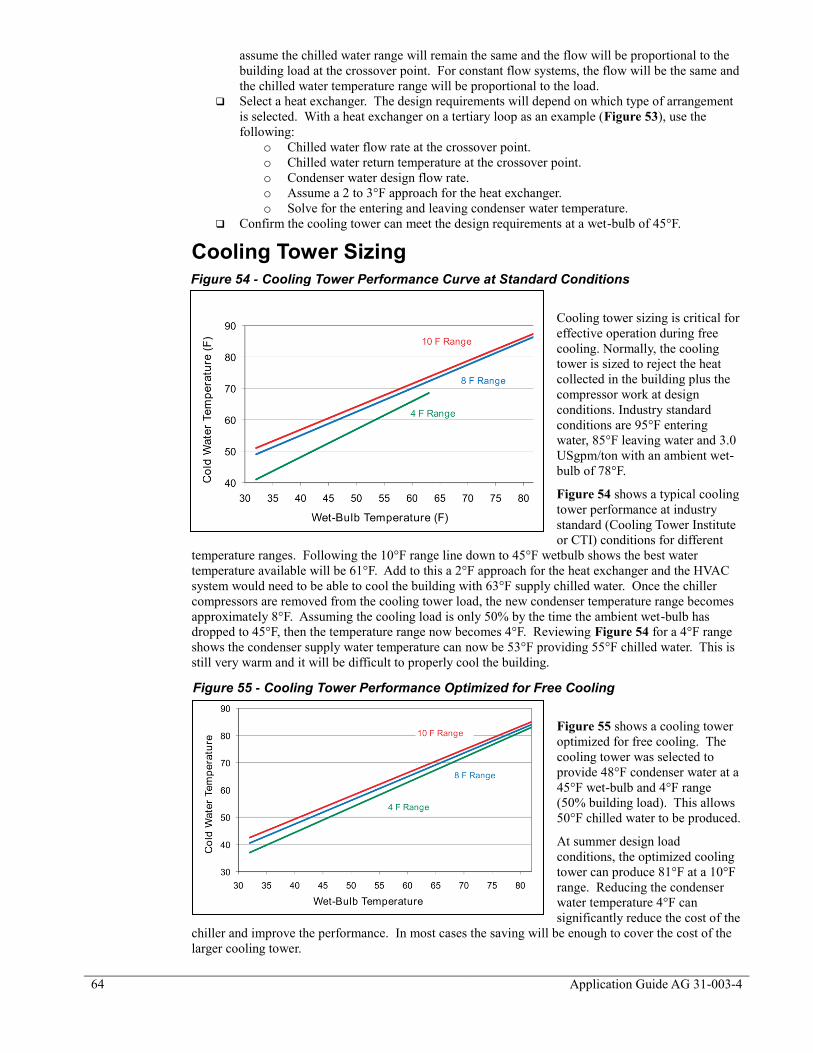
64
Application Guide AG 31-003-4
assume the chilled water range will remain the same and the flow will be proportional to the
building load at the crossover point. For constant flow systems, the flow will be the same and
the chilled water temperature range will be proportional to the load.
Select a heat exchanger. The design requirements will depend on which type of arrangement
is selected. With a heat exchanger on a tertiary loop as an example (Figure 53), use the
following:
o Chilled water flow rate at the crossover point.
o Chilled water return temperature at the crossover point.
o Condenser water design flow rate.
o Assume a 2 to 3°F approach for the heat exchanger.
o Solve for the entering and leaving condenser water temperature.
Confirm the cooling tower can meet the design requirements at a wet-bulb of 45°F.
Cooling Tower Sizing
Cooling tower sizing is critical for
effective operation during free
cooling. Normally, the cooling
tower is sized to reject the heat
collected in the building plus the
compressor work at design
conditions. Industry standard
conditions are 95°F entering
water, 85°F leaving water and 3.0
USgpm/ton with an ambient wet-
bulb of 78°F.
Figure 54 shows a typical cooling
tower performance at industry
standard (Cooling Tower Institute
or CTI) conditions for different
temperature ranges. Following the 10°F range line down to 45°F wetbulb shows the best water
temperature available will be 61°F. Add to this a 2°F approach for the heat exchanger and the HVAC
system would need to be able to cool the building with 63°F supply chilled water. Once the chiller
compressors are removed from the cooling tower load, the new condenser temperature range becomes
approximately 8°F. Assuming the cooling load is only 50% by the time the ambient wet-bulb has
dropped to 45°F, then the temperature range now becomes 4°F. Reviewing Figure 54 for a 4°F range
shows the condenser supply water temperature can now be 53°F providing 55°F chilled water. This is
still very warm and it will be difficult to properly cool the building.
Figure 55 shows a cooling tower
optimized for free cooling. The
cooling tower was selected to
provide 48°F condenser water at a
45°F wet-bulb and 4°F range
(50% building load). This allows
50°F chilled water to be produced.
At summer design load
conditions, the optimized cooling
tower can produce 81°F at a 10°F
range. Reducing the condenser
water temperature 4°F can
significantly reduce the cost of the
chiller and improve the performance. In most cases the saving will be enough to cover the cost of the
larger cooling tower.
Figure 54 - Cooling Tower Performance Curve at Standard Conditions
Figure 55 - Cooling Tower Performance Optimized for Free Cooling
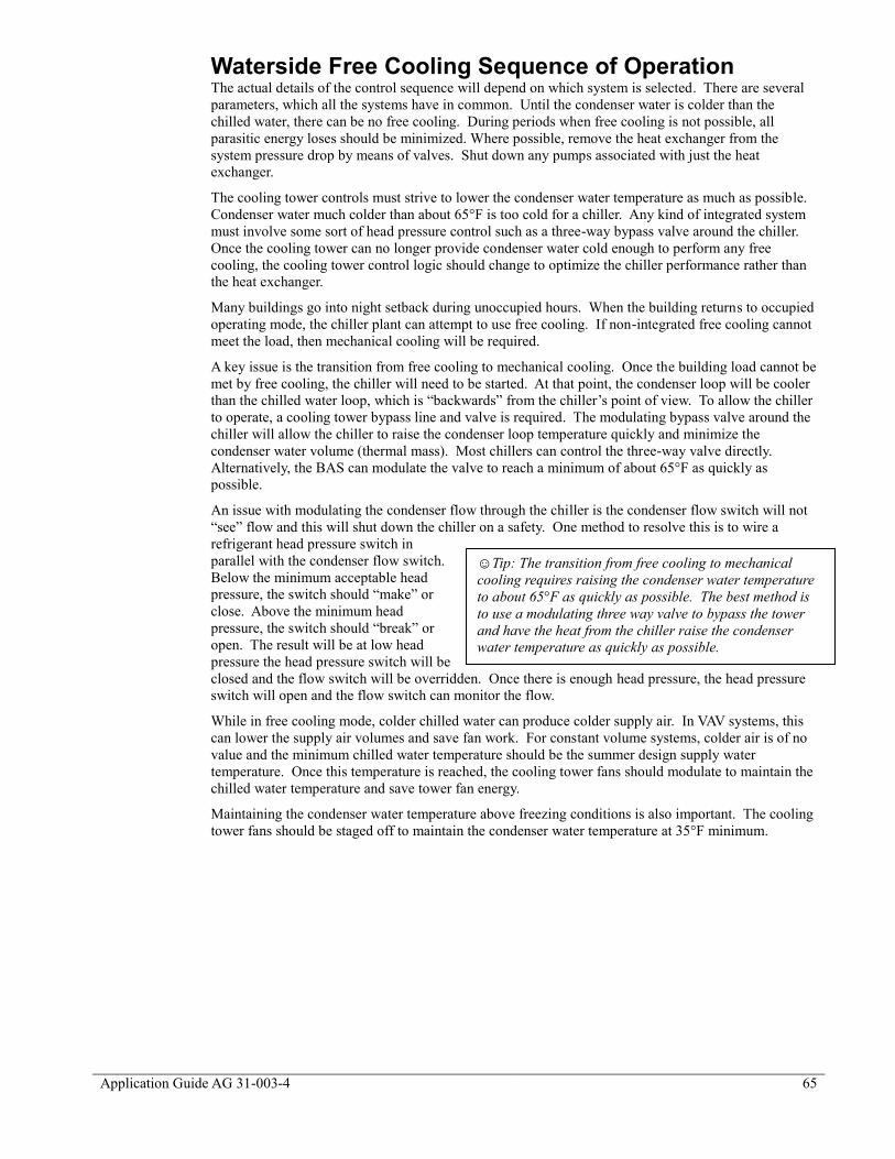
Application Guide AG 31-003-4 65
Waterside Free Cooling Sequence of Operation The actual details of the control sequence will depend on which system is selected. There are several
parameters, which all the systems have in common. Until the condenser water is colder than the
chilled water, there can be no free cooling. During periods when free cooling is not possible, all
parasitic energy loses should be minimized. Where possible, remove the heat exchanger from the
system pressure drop by means of valves. Shut down any pumps associated with just the heat
exchanger.
The cooling tower controls must strive to lower the condenser water temperature as much as possible.
Condenser water much colder than about 65°F is too cold for a chiller. Any kind of integrated system
must involve some sort of head pressure control such as a three-way bypass valve around the chiller.
Once the cooling tower can no longer provide condenser water cold enough to perform any free
cooling, the cooling tower control logic should change to optimize the chiller performance rather than
the heat exchanger.
Many buildings go into night setback during unoccupied hours. When the building returns to occupied
operating mode, the chiller plant can attempt to use free cooling. If non-integrated free cooling cannot
meet the load, then mechanical cooling will be required.
A key issue is the transition from free cooling to mechanical cooling. Once the building load cannot be
met by free cooling, the chiller will need to be started. At that point, the condenser loop will be cooler
than the chilled water loop, which is “backwards” from the chiller’s point of view. To allow the chiller
to operate, a cooling tower bypass line and valve is required. The modulating bypass valve around the
chiller will allow the chiller to raise the condenser loop temperature quickly and minimize the
condenser water volume (thermal mass). Most chillers can control the three-way valve directly.
Alternatively, the BAS can modulate the valve to reach a minimum of about 65°F as quickly as
possible.
An issue with modulating the condenser flow through the chiller is the condenser flow switch will not
“see” flow and this will shut down the chiller on a safety. One method to resolve this is to wire a
refrigerant head pressure switch in
parallel with the condenser flow switch.
Below the minimum acceptable head
pressure, the switch should “make” or
close. Above the minimum head
pressure, the switch should “break” or
open. The result will be at low head
pressure the head pressure switch will be
closed and the flow switch will be overridden. Once there is enough head pressure, the head pressure
switch will open and the flow switch can monitor the flow.
While in free cooling mode, colder chilled water can produce colder supply air. In VAV systems, this
can lower the supply air volumes and save fan work. For constant volume systems, colder air is of no
value and the minimum chilled water temperature should be the summer design supply water
temperature. Once this temperature is reached, the cooling tower fans should modulate to maintain the
chilled water temperature and save tower fan energy.
Maintaining the condenser water temperature above freezing conditions is also important. The cooling
tower fans should be staged off to maintain the condenser water temperature at 35°F minimum.
☺Tip: The transition from free cooling to mechanical
cooling requires raising the condenser water temperature
to about 65°F as quickly as possible. The best method is
to use a modulating three way valve to bypass the tower
and have the heat from the chiller raise the condenser
water temperature as quickly as possible.

66
Application Guide AG 31-003-4
Economizers and Energy Efficiency The goal of either airside or waterside economizers is to reduce energy usage. Economizer energy
analysis requires annual energy analysis. Airside economizers should be used where possible since in
all but the driest climates, airside economizers are more efficient than waterside economizers. An
exception to this is where high levels of humidification are required since humidification is expensive
and introducing large amounts of outdoor air for cooling would add to the humidification load.
ASHRAE Standard 90.1 lays down some simple guide lines when it comes to both airside and
waterside economizers. It presents parameters such as how big the fans can be and the general wet-
bulb and dry-bulb conditions needed to cool the entire building with only economizing. The most
recent version of the standard should be referenced for specifics pertaining to the aforementioned
topics.

Application Guide AG 31-003-4 67
Heat Recovery and Templifiers™
Chiller plants collect all the energy released in the building. In addition, there is an additional 25%
more energy from the chillers themselves because of the compressors. This represents a lot of heat that
can be used for other processes within the building. The challenge is that this is low-grade, 95°F heat
that is not very useful for anything. The solution is to use either heat recovery chillers or Daikin
Applied’s Templifier™ to raise the temperature of the water to a temperature that is useful. Common
uses for heat recovery water are:
HVAC system reheat
Domestic hot water
Snow melting
Process applications
Load Profiles A key issue with heat recovery is to understand the load profile of the chiller plant and the load profile
of the system that requires the heat. It is absolutely necessary to have a cooling load at the same time
there is a requirement for heat. While this may seem obvious, many reheat systems are designed to use
heat recovery hot water when the chiller plant is producing little or no heat.
In many cases the cooling load is
declining as the heat load is
increasing. An example is reheat
for VAV. Without a cooling load,
no heat can be collected. An
analysis must be performed to
identify the size and time of heating
load. Figure 56 shows the annual
cooling load and annual heating
load for a building. The shared
underneath both the curves is the
amount of heat available for
recovery. The size of the heat
recovery chiller should be the
highest point in this shared area.
For this example, the intersection of
the cooling and heating profiles
during September is the correct size.
HVAC systems that require winter chilled water, such as fancoils, buildings with process loads, etc.,
tend to be good candidates for a heat recovery chiller because of the large amount of time when there is
simultaneous heating and cooling.
Figure 56 - Cooling vs. Heating Load Profile
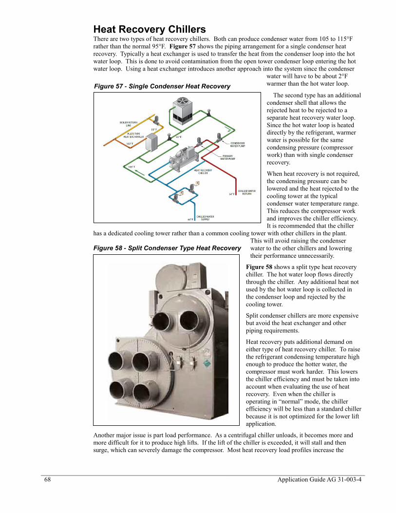
68
Application Guide AG 31-003-4
Heat Recovery Chillers There are two types of heat recovery chillers. Both can produce condenser water from 105 to 115°F
rather than the normal 95°F. Figure 57 shows the piping arrangement for a single condenser heat
recovery. Typically a heat exchanger is used to transfer the heat from the condenser loop into the hot
water loop. This is done to avoid contamination from the open tower condenser loop entering the hot
water loop. Using a heat exchanger introduces another approach into the system since the condenser
water will have to be about 2°F
warmer than the hot water loop.
The second type has an additional
condenser shell that allows the
rejected heat to be rejected to a
separate heat recovery water loop.
Since the hot water loop is heated
directly by the refrigerant, warmer
water is possible for the same
condensing pressure (compressor
work) than with single condenser
recovery.
When heat recovery is not required,
the condensing pressure can be
lowered and the heat rejected to the
cooling tower at the typical
condenser water temperature range.
This reduces the compressor work
and improves the chiller efficiency.
It is recommended that the chiller
has a dedicated cooling tower rather than a common cooling tower with other chillers in the plant.
This will avoid raising the condenser
water to the other chillers and lowering
their performance unnecessarily.
Figure 58 shows a split type heat recovery
chiller. The hot water loop flows directly
through the chiller. Any additional heat not
used by the hot water loop is collected in
the condenser loop and rejected by the
cooling tower.
Split condenser chillers are more expensive
but avoid the heat exchanger and other
piping requirements.
Heat recovery puts additional demand on
either type of heat recovery chiller. To raise
the refrigerant condensing temperature high
enough to produce the hotter water, the
compressor must work harder. This lowers
the chiller efficiency and must be taken into
account when evaluating the use of heat
recovery. Even when the chiller is
operating in “normal” mode, the chiller
efficiency will be less than a standard chiller
because it is not optimized for the lower lift
application.
Another major issue is part load performance. As a centrifugal chiller unloads, it becomes more and
more difficult for it to produce high lifts. If the lift of the chiller is exceeded, it will stall and then
surge, which can severely damage the compressor. Most heat recovery load profiles increase the
Figure 57 - Single Condenser Heat Recovery
Figure 58 - Split Condenser Type Heat Recovery

Application Guide AG 31-003-4 69
heating requirement as the cooling load reduces, setting up a situation where the chiller will be
partially loaded but expected to produce hot water.
To remedy the problem, hot gas bypass should be included with any heat recovery chiller. While this
will protect the chiller from surging, it may also waste a lot of power. For instance, if the hot gas valve
opens at 25% capacity, any output between 0 and 25% capacity will consume the power used at 25%
capacity. In short, the chiller may become a very large electric resistance heater!
Heat Recovery Chiller Control When a chiller is in heat recovery mode, it attempts to produce hot water as well as chilled water.
There are two common methods of control. The first is for the chiller to maintain a common condenser
return water temperature. For example, consider a chiller that is intended to produce 105°F supply hot
water with 95°F return hot water at full load. This control sequence will attempt to maintain the return
water temperature at 95°F. The supply hot water temperature will then fluctuate between 95 and 105
°F depending on the amount of heat rejected.
Basing the control on the return water temperature is easier on the chiller in terms of light load lift.
During period of light cooling load, the required condensing pressure drops as shown in Figure 59.
This reduces the chance of a surge or stall situation and reduces the use of hot gas bypass. A fixed
return hot water system (during heat recovery mode) will mean the supply hot water temperature
fluctuates as the heating load changes (assuming a constant hot water flow rate. The changes are
generally small somewhere between 3-5°F. The boiler can supplement the heat recovery and add
enough heat to maintain the return water temperature. The boiler control should be set up to provide
95°F return water during heat recovery. If desired, during non-heat recovery heating mode, the boiler
can operate on a fixed (e.g. 180°F) supply water temperature.
A second control arrangement is for the chiller to attempt to maintain a fixed supply hot water
temperature. This arrangement provides a constant supply temperature (105°F for example) for the hot
water system. It also requires the chiller to produce design condition refrigerant condensing pressures
even at very low chiller loads. This arrangement is harder on the chiller and will generally produce
less heat recovery than a control system that maintains a constant entering water temperature.
Raising the hot water temperature is accomplished through the cooling tower and bypass valve control.
To raise the water temperature for either single shell or split shell heat recovery, either the cooling
tower or the chiller bypass valve must be modulated to meet the required hot water temperature. The
cooling tower water temperature will be the same as the hot water temperature! Normal cooling tower
operation will need to be overridden. When there is no heat recovery required, (no heating load) the
control system should lower the condenser water temperature and follow whatever control sequence is
being used for conventional chillers (See Cooling Tower Controls).
Heat Recovery Chiller Selection Proper heat recovery chiller selection requires a clear understanding of the chilled water and hot water
load profiles. To produce the best results, the chilled water plant design should be optimized to take
full advantage of the load profiles. A common practice is to design the chilled water plant as if there
Figure 59 - Heat Recovery Control Options

70
Application Guide AG 31-003-4
was no heat recovery and then pick one of the chillers and rate it as a heat recovery chiller at design
cooling load conditions. The total heat of rejection from a heat recovery chiller operating at design
cooling is 1.25 times the design cooling capacity. While this sounds like a significant amount of
energy recovery, it does not mean the system will actually produce it. The chiller will only produce
this amount of heat recovery if it is fully loaded and all the other design parameters are met. The
following issues should be considered when selecting a heat recovery chiller:
Chiller Sizing. The chiller should be sized as close to the expected cooling load during heat
recovery as possible. It is important to have the chiller operating as close as possible to 100%
cooling load during heat recovery to provide the best refrigerant lift and to use the least
amount of hot gas bypass. The optimal size requires annual energy analysis.
Hot Water Temperature Ranges. Chillers are typically selected based on a 10°F range
while hot water systems are often designed for a 20°F range. Using a 20°F range for the
chiller is not recommended. Using tertiary piping for the chiller on the hot water loop allows
the chiller to be on a different temperature range and the pressure drop of the chiller is
avoided when not in use.
Hot Water Supply Temperature. Heat recovery chillers are limited in what they can
produce. The higher the water temperature, the more useful it is for heating. However, high
supply water temperatures are harder on the compressor, reduce the stable compressor
envelope and lower the chiller performance.
Boiler Interaction. It is easy to become fixated on maintaining the hot water supply setpoint
when the real goal is to produce as much heat recovery as possible. Understand how the
boiler and chiller interact to produce hot water. Try to collect as much heat as possible from
the chiller (even if the supply water temperature is not met) and trim with the boiler to meet
the required heating load.
Compressor Lift Limitations. The higher the compressor lift requirement, the smaller the
stable compressor envelope, and the sooner the compressor lift will be exceeded at part load.
Understand at what percentage of cooling load the compressor will no longer maintain the
required lift. Operation below this point will require hot gas bypass. Select the hot water
control sequence that produces the best result. Basing the hot water control on the return
water temperature may produce more heat recovery without hot gas bypass.
Chilled Water Plant Design for Heat Recovery Any chiller plant design can include a heat recovery chiller. Generally, only one chiller in a multiple
chiller plant is a heat recovery type. It should be the first chiller that is activated during cooling.
Another design possibility is to add a heat recovery chiller in the chilled water return line, but in a
tertiary loop. This chiller will reduce the load on the main chillers by lowering the return water
temperature. It will also allow all the heat recovered in the building to be available for heat recovery.
Chiller plant design can be “tuned” to optimize heat recovery. Here is a list of things to
consider:
Pick a chiller size that matches the chilled water load during heat recovery.
Backload the chiller by the placement of the decoupler (Refer to Primary Secondary
Systems).
Consider series chillers where the upstream chiller is the heat recovery chiller.
Use chilled water reset so the lift is reduced during heat recovery operation.
Evaluate a VFD chiller, which will operate more efficiently when not in heat recovery mode.
Avoid low chilled water design temperatures.
Impact on the Rest of the HVAC Design Where heat recovery will be used for heating, the chiller should tie into the boiler return. A tertiary
loop is recommended so the chiller heat recovery temperature range can be different than the boiler
loop range. The flow rates for the boiler and the heat recovery will mostly likely be different as well. A
tertiary loop also allows the pressure drop through the heat recovery chiller to be avoided when heat
recovery is not possible.
Most heating systems are designed for 170°F average water temperature. The use of heat recovery will
require the heating system to operate with water in the 105 to 115°F range. Whereas single row
heating coils in terminal heating units would have worked with a conventional design, now 3- or 4-
row heating coils may be required. These coils will add to the capital cost of the project. Further, they
will increase the fan static pressure drop every hour the fan system operates.

Application Guide AG 31-003-4 71
Domestic hot water systems range from 120°F for showers, baths, etc to 140°F for kitchens. These
temperatures exceed the capabilities of a heat recovery chiller, however, a heat recovery chiller can be
used for preheat. When heat recovery is used for domestic hot water, local codes may require an
isolating heat exchanger.
Templifiers™ A Templifier™ (Figure 60) is a water-to-water energy recovery device. It is capable of producing hot
water in the 140 to 160°F range with a COP between 3 and 5.
Templifiers™ can be used in any application
where heat recovery chillers are considered.
They can also be used in many other
applications where hotter water is required than
can be normally produced by heat recovery
chillers. Other applications include geothermal,
solar collecting, ground source, and closed loop
water source heat pumps.
Figure 61 shows a Templifier™ used in a
chiller plant system. In this arrangement the
Templifier™ can produce 140 to 160°F from
the heat of rejection of Chiller 1. It can do this while still allowing normal condenser relief for the first
chiller.
Templifier™ Control Templifiers™ are designed
to maintain the heating water
setpoint regardless of source
water conditions within the
limits of the machine.
Templifier™ Selection Templifier™ size should be
based on the heat load and
the source chiller total heat
of rejection. The best
method for selecting the
capacity is to perform an
annual analysis and identify
the balance point where the
heat source and the heat load
are largest. This can be a very involved calculation requiring several iterations. Most often energy
modeling should be performed to determine the correct size of a Templifier™. The following are some
alternative methods that can be used as a starting point to evaluate a design:
If the intent is to provide reheat for a VAV system, use the design reheat load from the
building winter design load calculations. This will be enough heat to raise all the supply air
from 55°F to 75°F with the VAV boxes at minimum flow. Assume the cooling load will be
50% of design. If there are two equally sized chillers, then the source chiller will be fully
loaded. The Templifier™ capacity should be the smaller of these two loads.
For a constant volume system, do the same as above but use the summer design reheat.
Constant volume with reheat systems use large amounts of reheat even in warm weather.
Fan coil systems offer an excellent opportunity since there is such a large overlap in heating
and cooling loads. Use the lesser of either the winter building envelope heat loss (less the
ventilation air) or the source chiller capacity times 1.25 for the chiller compressor work.
For domestic hot water applications, use the smaller of either the 50% of the chiller design
load or the design domestic hot water load.
Figure 60 - Daikin Applied Templifier™
Figure 61 - TemplifierTM
in a Condenser Loop

72
Application Guide AG 31-003-4
Templifiers™ are selected based on the leaving heating water temperature and the leaving source water
temperature. In most cases, the designer knows the desired heating water temperature and the entering
source water temperature at building design conditions (For condenser water heat recovery, this would
be the condenser water temperature leaving the chiller). It is important to select the Templifier™
based on the most demanding conditions expected during heat recovery. It is recommended that the
minimum entering condenser water for the chiller supplying the heat be set at 65°F. Assuming the
chiller is operating at 50% capacity during heat recovery mode, the supply water temperature to the
Templifier™ would be 70°F (based on a 10°F range for the condenser water).
The more source flow through the Templifier™, the warmer the leaving source water temperature will
be. When there is additional source flow available, it is recommended that the flow through the
Templifier™ be increased until the design temperature range is 5°F or the design flowrate is 4.8
USgpm/ton. Using the source supply water temperature and the Templifier™ load, the source leaving
water temperature can be calculated. More information on selecting Templifiers™ can be found in
Daikin Applied Templifier™ product catalog.
Chilled Water Plant Design for Templifier™ Heat Recovery Templifiers™ can use the condenser water of any chiller for a heat source. In some applications, it
may make sense to change the source chiller size to optimize heat recovery. It should be the first chiller
that is activated during cooling. A common condenser water loop for all the chillers in the plant allows
all the heat rejected by the chiller plant to be used for heat recovery by the Templifier™. Preferentially
loading the source chiller by the placement of the decoupler (See Figure 47) can also increase the heat
available for recovery.
Templifier™ Impact on the Rest of the HVAC Design Where heat recovery will be used for reheat, the Templifier™ should tie into the boiler return. A
tertiary loop is recommended so the Templifier™ temperature range can be different than the boiler
loop range. The flow rates for the boiler and the Templifier™ will mostly likely be different as well. A
tertiary loop also allows the pressure drop through the Templifier™ to be avoided when heat recovery
is not possible.
Most heating systems are designed for 180°F average water temperature. A Templifier can provide
140 to 160°F water, which is typically enough to provide reheat during the spring and fall periods
without having to increase the size of reheat coils. During the winter season, the hotter water from the
boiler can be used for the larger loads experienced by the reheat coils. The reheat coils should be sized
for the winter load and boiler design supply temperature.
Domestic hot water systems range from 120°F for showers, baths, etc. to 140°F for kitchens. The
Templifier can supply water at these temperatures. When heat recovery is used for domestic hot water,
local codes may require an isolating heat exchanger.
ASHRAE Standard 90.1
ASHRAE Standard 90.1 makes several references to condenser heat recovery. Here is a list of items:
There is a requirement for condenser heat recovery to be used to preheat domestic hot water
for;
o Facilities open 24 hours a day.
o Total heat of rejection from the chiller plant is 6,000,000 Btu/hr or greater (About a
400-ton plant).
o Domestic hot water load exceeds 1,000,000 Btu/hr.
o The system must be able to either use 60% of the chiller peak rejection load at design
conditions or preheat the domestic hot water to 85°F.
There is an exemption for the requirement for economizers if condenser heat recovery is used
for domestic hot water.
There is an exemption for simultaneous heating and cooling if 75% of the energy used for
reheat comes from energy recovery such as condenser heat recovery. This can be helpful
with some VAV with reheat designs.
There is an exemption for pool covers for pools heated to 90°F if 60% of the heat comes from
site recovered energy.
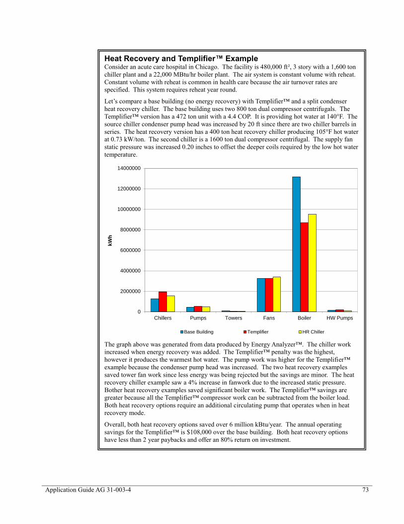
Application Guide AG 31-003-4 73
Heat Recovery and Templifier™ Example Consider an acute care hospital in Chicago. The facility is 480,000 ft², 3 story with a 1,600 ton
chiller plant and a 22,000 MBtu/hr boiler plant. The air system is constant volume with reheat.
Constant volume with reheat is common in health care because the air turnover rates are
specified. This system requires reheat year round.
Let’s compare a base building (no energy recovery) with Templifier™ and a split condenser
heat recovery chiller. The base building uses two 800 ton dual compressor centrifugals. The
Templifier™ version has a 472 ton unit with a 4.4 COP. It is providing hot water at 140°F. The
source chiller condenser pump head was increased by 20 ft since there are two chiller barrels in
series. The heat recovery version has a 400 ton heat recovery chiller producing 105°F hot water
at 0.73 kW/ton. The second chiller is a 1600 ton dual compressor centrifugal. The supply fan
static pressure was increased 0.20 inches to offset the deeper coils required by the low hot water
temperature.
The graph above was generated from data produced by Energy Analyzer™. The chiller work
increased when energy recovery was added. The Templifier™ penalty was the highest,
however it produces the warmest hot water. The pump work was higher for the Templifier™
example because the condenser pump head was increased. The two heat recovery examples
saved tower fan work since less energy was being rejected but the savings are minor. The heat
recovery chiller example saw a 4% increase in fanwork due to the increased static pressure.
Bother heat recovery examples saved significant boiler work. The Templifier™ savings are
greater because all the Templifier™ compressor work can be subtracted from the boiler load.
Both heat recovery options require an additional circulating pump that operates when in heat
recovery mode.
Overall, both heat recovery options saved over 6 million kBtu/year. The annual operating
savings for the Templifier™ is $108,000 over the base building. Both heat recovery options
have less than 2 year paybacks and offer an 80% return on investment.
0
2000000
4000000
6000000
8000000
10000000
12000000
14000000
Chillers Pumps Towers Fans Boiler HW Pumps
kW
h
Base Building Templifier HR Chiller

74
Application Guide AG 31-003-4
Variable Primary Flow Design
Modern DDC controllers on chillers allow the possibility of variable flow design. Traditional thinking
has been that the chiller should see constant flow and then the load will vary directly with the return
fluid temperature. Allowing variable flow means the cooling load can vary either with the return fluid
temperature or a change in the chilled water flow. It requires modern controllers to deal with two
variables and provide stable chiller operation.
Basic Operation Figure 62 shows a two chiller variable primary flow system. Variable primary flow can be applied to
single, parallel, or series chiller plants although parallel is the most common. The control valve at the
cooling loads are two-way type so the chilled water flow varies with the cooling load. The primary
pump for the chillers circulates the chilled water throughout the building. The chilled water flow
varies through the chillers as well. This is the main difference between variable primary flow and
primary/secondary flow.
Variable primary flow provides
pump savings over primary
secondary systems because all
the chilled water being pumped is
being used for cooling. In a
primary secondary system, any
flow through the decoupler
consumes pump power but
provides no cooling.
There is a bypass line to maintain
minimum flow through the
chillers only. Whenever the
chilled water flow is above
minimum, the bypass is closed.
Basic Components Chillers Almost any type of chiller can be used including air cooled and water cooled. The chiller must have a
unit controller capable of dealing with both a change in flow and a change in return temperature. In
most cases, the controller should be a modern digital type, using a PID loop control. Check with the
manufacturer whether the controller is capable of variable primary flow. Usually, the controller can be
upgraded on an existing unit if required.
The range of flow rates in the chiller is limited at the low end by laminar flow in the tubes (2 to 3 fps
tube velocity) and at the high end by tube erosion and vibration (10 to12 fps tube velocity). Chiller
selection software typically tries to pick a tube velocity of around 6 fps, which provides a good balance
between water pressure drop and heat transfer performance. Half the typical design flow rate will
result in 3 fps tube velocities which is about the minimum. The actual minimum should be provided
by the manufacturer and is often included in computer selections.
Selecting the chiller with tube velocities
at design conditions near 10 fps allows
the system flow to be turned down to
30% of design flow. This may be
advantageous where there is only one
chiller in the system with few operating
hours at design flow.
Figure 62 - Basic Variable Primary Flow Operation
☺Tip: Usually, the minimum flow rate of a chiller is
50% of the design flow rate. This value can be used
to size the bypass line. The bypass line should be
capable of handling the minimum flow of the largest
chiller.
Application Guide AG 31-003-4 75
In most cases, the chillers will be the same size. The flow ranges and capacities must be carefully
considered so that there are no operating points where no combination of chillers can meet the load.
For example, if two evenly identical chillers have a minimum flow rate 60% of design, there will be a
“hole” between 50 and 60% of plant capacity. One chiller can meet the load up to 50% of plant
capacity. However, at say 55% two chillers will be required but the flowrate will be less than the
minimum required. Careful chiller selection (preferred since it is more energy efficient) and the use on
the bypass will resolve this problem.
Pumps The chilled water pump is variable flow (see Pumping Basics). They are sized to provide enough head
to circulate chilled water throughout the building. Automatic isolating valves are provided in front of
each chiller to stop flow when the chiller is not operating. Pumps can be dedicated to each chiller or in
the main return line, as shown in Figure 62. Common pumps allow over pumping and sharing a spare
pump.
Bypass Line The bypass should be sized for the minimum flow rate of the largest chiller being used. It is only used
to provide minimum flow to a chiller when the flow requirement through the chiller plant is less than
the chiller minimum flow.
The bypass line can be located between the chillers and the loads, as shown in Figure 62. This is the
same location as the decoupler is in a conventional primary secondary system. The bypass line could
also be placed at the end of the cooling loop. The bypass control valves will see a smaller pressure
drop but there may be some additional pump work.
Alternatively, some cooling loads could use three-way valves, which would provide the minimum flow
required. On the other hand these valves will bypass chilled water any time they are not operating at
design load, which wastes pump work and leads to low delta T syndrome.
When flow is required through the bypass line, it must be controlled. A modulating two or three-way
valve is required.
Variable Primary Flow Sequence of Operation Although a variable primary flow system is no more difficult to design than a primary secondary
system, the control sequences must be carefully thought out and commissioned. A building automation
system (BAS) capable of variable primary flow is a must. Direct communication between the BAS and
the chiller unit controllers is strongly recommended as well. This can be accomplished with standard
open control protocols such as BACnet or LonTalk.
Primary Pump Control The primary pump is controlled in the same manner as a secondary pump in a primary secondary
system (Refer to Pumping Basics).
Modulating both the flow and temperature range through a chiller requires time for the chiller
controller to respond. Many factors influence the rate of change of the flow including the chiller type,
the chiller controller logic, and the actual load on the chiller at the time. Some field adjustment of the
rate of change time should be expected during commissioning. A good starting point is 10% change in
flow per minute. This will affect the modulating rate of the primary pumps and the terminal unit
control valves.
Bypass Line Valve Control It is recommended that each chiller should have a flow meter. The meter can be used to recognize both
minimum and maximum flow constraints. Individual chiller meters allow each chiller’s flow rate to
monitored, which may be advantageous in some chiller plant control concepts such as over pumping or
deliberately operating multiple high part load efficient chillers in lieu of a single chiller.
It is possible to use only one flow meter in the common chilled water supply line upstream of the
bypass line. Assuming only one chiller is operating when minimum flow becomes an issue, the flow
measured at this point would be the flow through the operating chiller.
The bypass line control valve is controlled by a signal from the flow meter of the operating chiller.
The control system should recognize the chiller and know the minimum flow rate for that chiller. In
most cases the chillers are all the same, and hence there is only one minimum flow rate for the entire
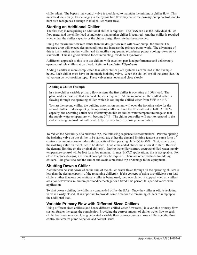
76
Application Guide AG 31-003-4
chiller plant. The bypass line control valve is modulated to maintain the minimum chiller flow. This
must be done slowly. Fast changes in the bypass line flow may cause the primary pump control loop to
hunt as it recognizes a change in total chilled water flow.
Starting an Additional Chiller The first step is recognizing an additional chiller is required. The BAS can use the individual chiller
flow meter and the chiller load as indicators that another chiller is required. Another chiller is required
when either the chiller capacity or the chiller design flow rate has been reached.
Using the maximum flow rate rather than the design flow rate will “over pump” the chiller. The
pressure drop will exceed design conditions and increase the primary pump work. The advantage of
this is that starting another chiller and its ancillary equipment (condenser pump, cooling tower etc) is
staved off. This is a good method for counteracting low delta T syndrome.
A different approach to this is to use chillers with excellent part load performance and deliberately
operate multiple chillers at part load. Refer to Low Delta T Syndrome.
Adding a chiller is more complicated than other chiller plant systems as explained in the example
below. Each chiller must have an automatic isolating valve. When the chillers are all the same size, the
valves can be two-position type. These valves must open and close slowly.
To reduce the possibility of a nuisance trip, the following sequence is recommended. Prior to opening
the isolating valve on the chiller to be started, use either the demand limiting feature or some form of
controls communication to reduce the capacity of the operating chiller(s) to 50%. Next, slowly open
the isolating valve on the chiller to be started. Enable the added chiller and allow it to start. Release
the demand limiting on the original chiller(s). During the chiller startup, accurate chilled water supply
temperature control will be lost for a few minutes. In most HVAC applications, this is acceptable. For
close tolerance designs, a different concept may be required. There are other methods for adding
chillers. The goal is to add the chiller and avoid a nuisance trip or damage to the equipment.
Shutting Down a Chiller A chiller can be shut down when the sum of the chilled water flows through all the operating chillers is
less than the design capacity of the remaining chiller(s). If the concept of using two efficient part load
chillers rather than one conventional chiller is being used, then one chiller is stopped when all chillers
are at or below their minimum part load percentage for a fixed time period; this period varies with
application.
To shut down a chiller, the chiller is commanded off by the BAS. Once the chiller is off, its isolating
valve is slowly closed. It is important to provide some time for the remaining chillers to ramp up to
the additional load.
Variable Primary Flow with Different Sized Chillers Using different sized chillers (and hence different chilled water flow rates,) in a variable primary flow
system further increases the complexity. Providing the correct amount of chiller water flow to each
chiller becomes an issue. Using dedicated variable flow primary pumps allows chiller specific flow
control but creates pump selection and control issues.
Adding a Chiller Example
In a two-chiller variable primary flow system, the first chiller is operating at 100% load. The
plant load increases so that a second chiller is required. At this moment, all the chilled water is
flowing through the operating chiller, which is cooling the chilled water from 54°F to 44°F.
To start the second chiller, the building automation system will open the isolating valve for the
second chiller. If done quickly, the operating chiller will see the flow rate cut in half. At 100%
capacity, the operating chiller will effectively double its chilled water temperature range so that
the supply water temperature will become 34°F! The chiller controller will start to respond to the
sudden change in load but will most likely trip on a freeze or low pressure safety.
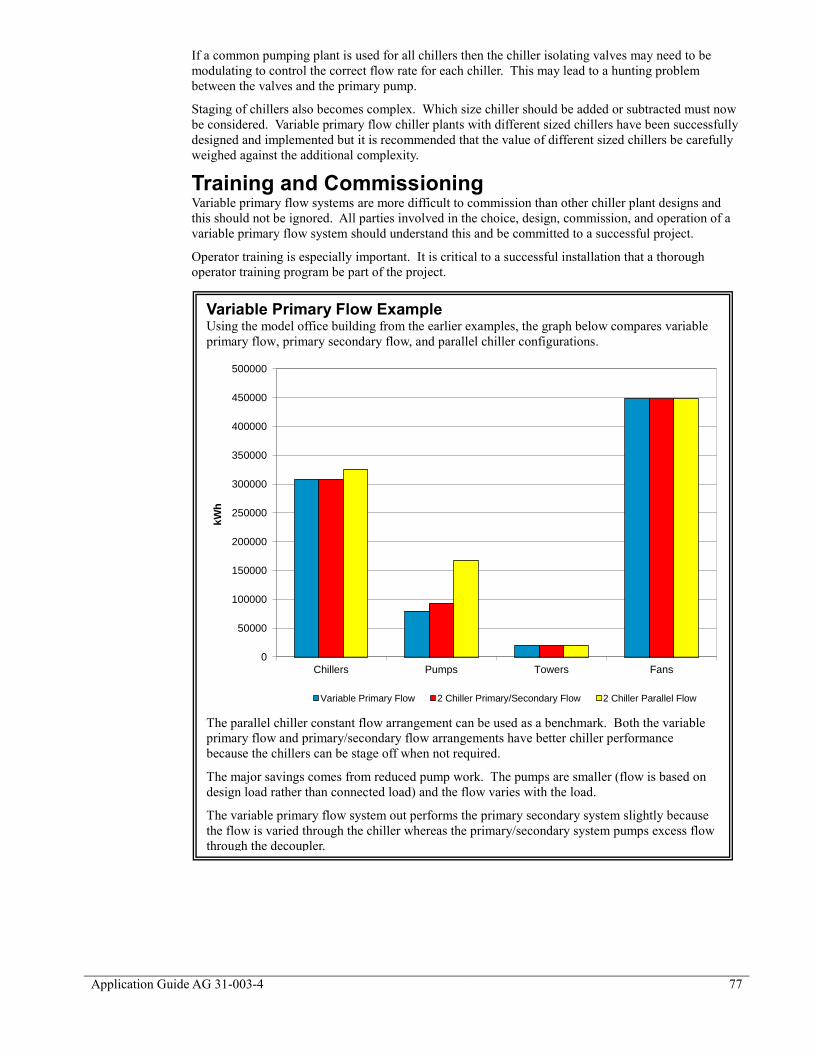
Application Guide AG 31-003-4 77
If a common pumping plant is used for all chillers then the chiller isolating valves may need to be
modulating to control the correct flow rate for each chiller. This may lead to a hunting problem
between the valves and the primary pump.
Staging of chillers also becomes complex. Which size chiller should be added or subtracted must now
be considered. Variable primary flow chiller plants with different sized chillers have been successfully
designed and implemented but it is recommended that the value of different sized chillers be carefully
weighed against the additional complexity.
Training and Commissioning Variable primary flow systems are more difficult to commission than other chiller plant designs and
this should not be ignored. All parties involved in the choice, design, commission, and operation of a
variable primary flow system should understand this and be committed to a successful project.
Operator training is especially important. It is critical to a successful installation that a thorough
operator training program be part of the project.
Variable Primary Flow Example Using the model office building from the earlier examples, the graph below compares variable
primary flow, primary secondary flow, and parallel chiller configurations.
The parallel chiller constant flow arrangement can be used as a benchmark. Both the variable
primary flow and primary/secondary flow arrangements have better chiller performance
because the chillers can be stage off when not required.
The major savings comes from reduced pump work. The pumps are smaller (flow is based on
design load rather than connected load) and the flow varies with the load.
The variable primary flow system out performs the primary secondary system slightly because
the flow is varied through the chiller whereas the primary/secondary system pumps excess flow
through the decoupler.
0
50000
100000
150000
200000
250000
300000
350000
400000
450000
500000
Chillers Pumps Towers Fans
kW
h
Variable Primary Flow 2 Chiller Primary/Secondary Flow 2 Chiller Parallel Flow

78
Application Guide AG 31-003-4
Low Delta T Syndrome
Low delta T syndrome occurs when the design chilled water temperature range is not maintained. Any
variable flow system can experience low delta T and the problem is exacerbated at part load. In severe
cases, the chilled water range has dropped from 12°F design to 2°F. When this occurs, the flow rate
must be increased significantly to provide cooling in the building. The following section will expand
more on causes and solutions for low delta T syndrome.
Low Delta T Example Figure 63 shows a basic primary secondary loop operating at full load. In this example, the system
design load is 400 tons, the flow rates and temperatures are at standard AHRI conditions and the load
has a two-way control valve. The loop with the chiller is called the primary loop. The loop with the
load is the secondary loop. The common pipe is sometimes referred to as the decoupler.
At full load, the design
flow of 960 USgpm passes
through the chillers, the
two pumps, the load, and
back to the chillers. There
is no flow through the
common pipe. At first, it
would appear that the flow
is being pumped twice.
Although this is true, the
total head is split between
the two sets of pumps.
The primary pumps are
only sized for the primary
loop of the system. This
means that they are sized
for the chiller pressure
drop and any fittings in
the primary loop. The
secondary pumps are sized
for the pressure drop
“outside the mechanical room”. The higher pressure drops and larger piping arrangements in the
secondary loop justify the variable flow.
Figure 64 shows the same
example operating at 67%
capacity. The two-way
control valves at the load has
reduced the flow in the
secondary loop to 643
USgpm. The delta T across
the load remains at 10°F.
The primary pumps are
constant flow pumps sized for
their designated chiller’s
design flow. It remains
constant at 720 USgpm
because one of the chillers is
off at 67% load. The
additional flow not required
in the secondary loop (77
USgpm) passes through the
common pipe to the chiller
Figure 63 - Primary Secondary Loop at Full Load
Figure 64 - Primary Secondary Loop at 67% Load
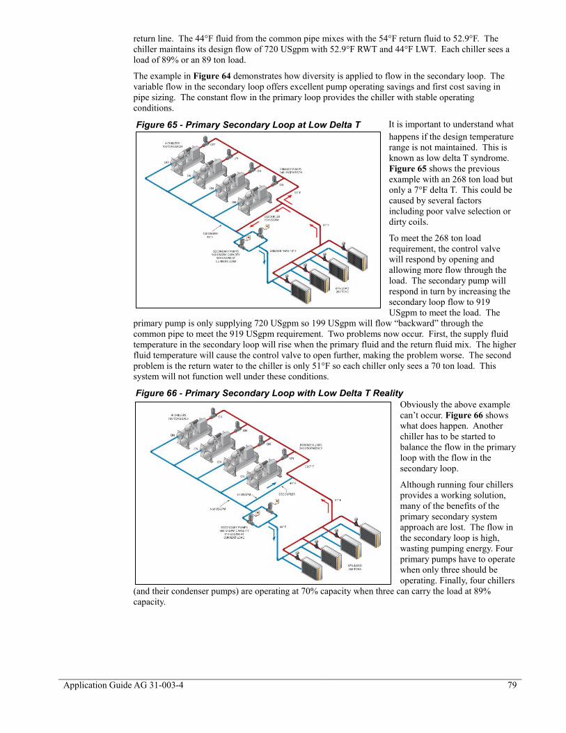
Application Guide AG 31-003-4 79
return line. The 44°F fluid from the common pipe mixes with the 54°F return fluid to 52.9°F. The
chiller maintains its design flow of 720 USgpm with 52.9°F RWT and 44°F LWT. Each chiller sees a
load of 89% or an 89 ton load.
The example in Figure 64 demonstrates how diversity is applied to flow in the secondary loop. The
variable flow in the secondary loop offers excellent pump operating savings and first cost saving in
pipe sizing. The constant flow in the primary loop provides the chiller with stable operating
conditions.
It is important to understand what
happens if the design temperature
range is not maintained. This is
known as low delta T syndrome.
Figure 65 shows the previous
example with an 268 ton load but
only a 7°F delta T. This could be
caused by several factors
including poor valve selection or
dirty coils.
To meet the 268 ton load
requirement, the control valve
will respond by opening and
allowing more flow through the
load. The secondary pump will
respond in turn by increasing the
secondary loop flow to 919
USgpm to meet the load. The
primary pump is only supplying 720 USgpm so 199 USgpm will flow “backward” through the
common pipe to meet the 919 USgpm requirement. Two problems now occur. First, the supply fluid
temperature in the secondary loop will rise when the primary fluid and the return fluid mix. The higher
fluid temperature will cause the control valve to open further, making the problem worse. The second
problem is the return water to the chiller is only 51°F so each chiller only sees a 70 ton load. This
system will not function well under these conditions.
Obviously the above example
can’t occur. Figure 66 shows
what does happen. Another
chiller has to be started to
balance the flow in the primary
loop with the flow in the
secondary loop.
Although running four chillers
provides a working solution,
many of the benefits of the
primary secondary system
approach are lost. The flow in
the secondary loop is high,
wasting pumping energy. Four
primary pumps have to operate
when only three should be
operating. Finally, four chillers
(and their condenser pumps) are operating at 70% capacity when three can carry the load at 89%
capacity.
Figure 65 - Primary Secondary Loop at Low Delta T
Figure 66 - Primary Secondary Loop with Low Delta T Reality
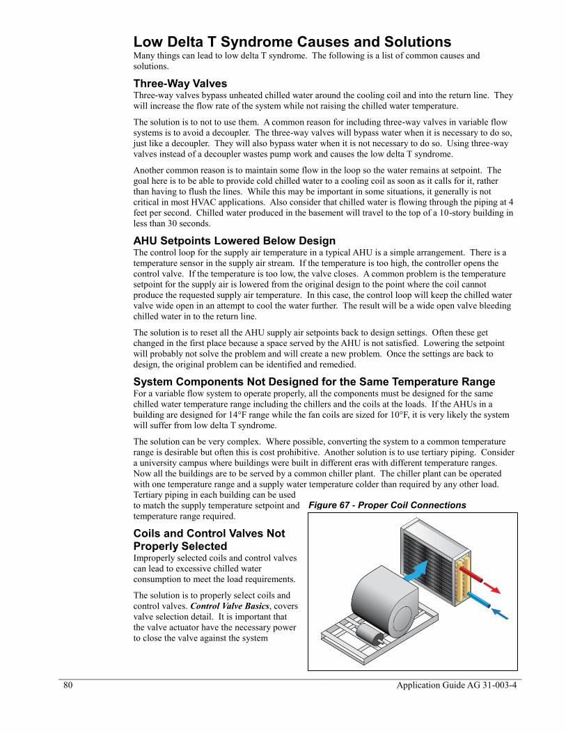
80
Application Guide AG 31-003-4
Low Delta T Syndrome Causes and Solutions Many things can lead to low delta T syndrome. The following is a list of common causes and
solutions.
Three-Way Valves Three-way valves bypass unheated chilled water around the cooling coil and into the return line. They
will increase the flow rate of the system while not raising the chilled water temperature.
The solution is to not to use them. A common reason for including three-way valves in variable flow
systems is to avoid a decoupler. The three-way valves will bypass water when it is necessary to do so,
just like a decoupler. They will also bypass water when it is not necessary to do so. Using three-way
valves instead of a decoupler wastes pump work and causes the low delta T syndrome.
Another common reason is to maintain some flow in the loop so the water remains at setpoint. The
goal here is to be able to provide cold chilled water to a cooling coil as soon as it calls for it, rather
than having to flush the lines. While this may be important in some situations, it generally is not
critical in most HVAC applications. Also consider that chilled water is flowing through the piping at 4
feet per second. Chilled water produced in the basement will travel to the top of a 10-story building in
less than 30 seconds.
AHU Setpoints Lowered Below Design The control loop for the supply air temperature in a typical AHU is a simple arrangement. There is a
temperature sensor in the supply air stream. If the temperature is too high, the controller opens the
control valve. If the temperature is too low, the valve closes. A common problem is the temperature
setpoint for the supply air is lowered from the original design to the point where the coil cannot
produce the requested supply air temperature. In this case, the control loop will keep the chilled water
valve wide open in an attempt to cool the water further. The result will be a wide open valve bleeding
chilled water in to the return line.
The solution is to reset all the AHU supply air setpoints back to design settings. Often these get
changed in the first place because a space served by the AHU is not satisfied. Lowering the setpoint
will probably not solve the problem and will create a new problem. Once the settings are back to
design, the original problem can be identified and remedied.
System Components Not Designed for the Same Temperature Range For a variable flow system to operate properly, all the components must be designed for the same
chilled water temperature range including the chillers and the coils at the loads. If the AHUs in a
building are designed for 14°F range while the fan coils are sized for 10°F, it is very likely the system
will suffer from low delta T syndrome.
The solution can be very complex. Where possible, converting the system to a common temperature
range is desirable but often this is cost prohibitive. Another solution is to use tertiary piping. Consider
a university campus where buildings were built in different eras with different temperature ranges.
Now all the buildings are to be served by a common chiller plant. The chiller plant can be operated
with one temperature range and a supply water temperature colder than required by any other load.
Tertiary piping in each building can be used
to match the supply temperature setpoint and
temperature range required.
Coils and Control Valves Not Properly Selected Improperly selected coils and control valves
can lead to excessive chilled water
consumption to meet the load requirements.
The solution is to properly select coils and
control valves. Control Valve Basics, covers
valve selection detail. It is important that
the valve actuator have the necessary power
to close the valve against the system
Figure 67 - Proper Coil Connections
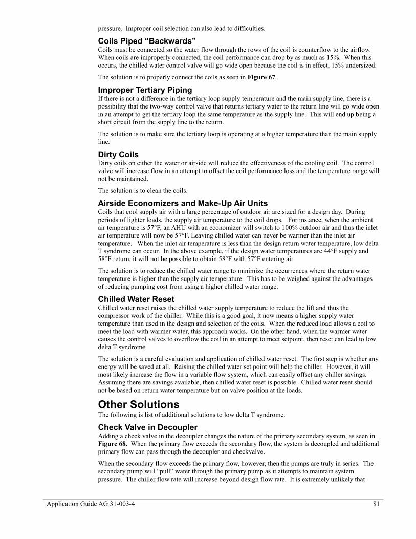
Application Guide AG 31-003-4 81
pressure. Improper coil selection can also lead to difficulties.
Coils Piped “Backwards” Coils must be connected so the water flow through the rows of the coil is counterflow to the airflow.
When coils are improperly connected, the coil performance can drop by as much as 15%. When this
occurs, the chilled water control valve will go wide open because the coil is in effect, 15% undersized.
The solution is to properly connect the coils as seen in Figure 67.
Improper Tertiary Piping If there is not a difference in the tertiary loop supply temperature and the main supply line, there is a
possibility that the two-way control valve that returns tertiary water to the return line will go wide open
in an attempt to get the tertiary loop the same temperature as the supply line. This will end up being a
short circuit from the supply line to the return.
The solution is to make sure the tertiary loop is operating at a higher temperature than the main supply
line.
Dirty Coils Dirty coils on either the water or airside will reduce the effectiveness of the cooling coil. The control
valve will increase flow in an attempt to offset the coil performance loss and the temperature range will
not be maintained.
The solution is to clean the coils.
Airside Economizers and Make-Up Air Units Coils that cool supply air with a large percentage of outdoor air are sized for a design day. During
periods of lighter loads, the supply air temperature to the coil drops. For instance, when the ambient
air temperature is 57°F, an AHU with an economizer will switch to 100% outdoor air and thus the inlet
air temperature will now be 57°F. Leaving chilled water can never be warmer than the inlet air
temperature. When the inlet air temperature is less than the design return water temperature, low delta
T syndrome can occur. In the above example, if the design water temperatures are 44°F supply and
58°F return, it will not be possible to obtain 58°F with 57°F entering air.
The solution is to reduce the chilled water range to minimize the occurrences where the return water
temperature is higher than the supply air temperature. This has to be weighed against the advantages
of reducing pumping cost from using a higher chilled water range.
Chilled Water Reset Chilled water reset raises the chilled water supply temperature to reduce the lift and thus the
compressor work of the chiller. While this is a good goal, it now means a higher supply water
temperature than used in the design and selection of the coils. When the reduced load allows a coil to
meet the load with warmer water, this approach works. On the other hand, when the warmer water
causes the control valves to overflow the coil in an attempt to meet setpoint, then reset can lead to low
delta T syndrome.
The solution is a careful evaluation and application of chilled water reset. The first step is whether any
energy will be saved at all. Raising the chilled water set point will help the chiller. However, it will
most likely increase the flow in a variable flow system, which can easily offset any chiller savings.
Assuming there are savings available, then chilled water reset is possible. Chilled water reset should
not be based on return water temperature but on valve position at the loads.
Other Solutions The following is list of additional solutions to low delta T syndrome.
Check Valve in Decoupler Adding a check valve in the decoupler changes the nature of the primary secondary system, as seen in
Figure 68. When the primary flow exceeds the secondary flow, the system is decoupled and additional
primary flow can pass through the decoupler and checkvalve.
When the secondary flow exceeds the primary flow, however, then the pumps are truly in series. The
secondary pump will “pull” water through the primary pump as it attempts to maintain system
pressure. The chiller flow rate will increase beyond design flow rate. It is extremely unlikely that
82
Application Guide AG 31-003-4
enough flow will be drawn through the chiller to damage it. In most cases, the chiller can handle a
50% increase in flow which would result in a huge pressure drop. It is unlikely the pumps could
provide enough head.
By over pumping a chiller, the system can meet the required flow rate and load, and avoid starting a
second chiller and the additional pumps and tower.
Increasing the chiller flow rate offers some unique possibilities. If there is condenser relief available,
then the chiller may be able to produce more than its design capacity (For example a 100-ton chiller
may produce 110 tons with condenser relief). To take advantage of the extra capacity, the system
would have to increase the temperature range across the chiller (difficult to do since the system is
typically experiencing just the opposite!) or the flow rate would have to be increased. By over
pumping a chiller, it may be possible to produce more than the design capacity and avoid additional
pumps and tower work.
Adding a check valve effectively
makes the system variable primary
flow during low delta T intervals.
System control becomes more
complicated as well. How and at
what point is a second chiller added?
It is recommended that check valves
not be added to primary secondary
systems as part of the design. If
variable primary flow is the intention,
then the system should be designed
with that goal in mind. When a
system is exhibiting signs of low
delta T syndrome, the previous
remedies should be investigated first
prior to adding a check valve.
VFD or Dual Compressor Chillers The main problem with low delta T syndrome is the increase in energy usage due to multiple chillers,
pumps and towers operating to meet a light load. VFD and dual compressor chillers offer a different
solution. The high part load efficiency of these kinds of chillers promotes operating two chillers rather
than one to meet the load. Two VFD or dual compressor chillers operating partly loaded can consume
less energy than one chiller operating fully loaded. If the energy savings offset the penalty of the
pumps and tower, then VFD and dual compressor chillers are good solutions to low delta T syndrome.
Over Size Primary Pumps Over sizing the primary pumps allows the additional flow to be pumped through the chillers and
maintain the primary flow above the secondary flow. Over pumping a chiller can also allow any
additional capacity in the chiller to be utilized.
Reduce Temperature Range on Primary Side Reducing the chilled water temperature range on the primary side increases the flow rate for the same
capacity. During periods of light load, when low delta T syndrome occurs, the lower delta T and
higher flow rate on the primary side will counter act problems on the secondary side.
One drawback is the additional pump work on the primary side wastes energy at all operating points.
The possible savings offered by avoiding low delta T syndrome at light loads may be offset by the
penalty created at other operating points.
Add Flow Control Valves at Each Coil Adding flow control valves at each load, rated for the maximum flow rate, will ensure the load won’t
consume too much chilled water. From the chiller plant’s perspective, this will avoid low delta T,
however, space serviced by the coil may not be satisfied. In addition, most control valves create a
pressure drop that the chilled water pumps must be sized to overcome. Overcoming the additional
pressure drop will add to the annual cost of operating the pumps.
Figure 68 - Check Valve in Decoupler

Application Guide AG 31-003-4 83
Variable Primary Flow Low delta T syndrome occurs because of issues at the loads (coils). These will happen with variable
primary flow or primary secondary systems. Variable primary flow (VPF) does allow several solutions
to be easily implemented:
Do not have a decoupler that allows return chilled water to flow into the supply side. Return
chilled water will raise the supply water temperature and exacerbate the problem.
VPF allows chillers to be over pumped. See Check Valve in Decoupler.
VPF systems typically have flow meters, which can help the operator recognize a low delta T
situation and be used by the BAS to remedy the problem.

84
Application Guide AG 31-003-4
Process Applications
Process applications can place unique demands on chiller plants. All parties involved in a process
application should be fully aware that it is a process and not an HVAC application to avoid any
confusion.
Process Load Profiles Process loads can be broken down in to specialized environments and chilled water requirements for
the actual processes. Specialized environments such as low relative humidity (RH) for pharmaceutical
or confectionery manufacturers are an extension of conventional HVAC design.
Chilled water for processes and equipment can be quite a bit different than HVAC design. Remember
that process loads generally have very little to do with ambient conditions. It is quite possible that the
process will be operating at 5% on the hottest day of the year and 100% on the coldest day. It is
extremely important to gather as much information about the process, the load profile the operating
conditions, etc., as possible. Adding a process load to an HVAC chiller plant without this
consideration can lead to very poor performance.
The designer should gather at least the following information:
The process design load. Is it constant? Is it stepped or a batch load?
Are there multiple process loads with different needs? Do they have to be handled
individually or can a common system serve both?
The operating hours. Is it every hour of the year? Is it only in the summer? This will lead to
a discussion about redundancy. In HVAC design, redundancy often means there are at least
two pieces of equipment but not necessarily enough capacity to meet the design load if one of
them should fail. In process applications, redundancy usually means 100% backup so no
production time is lost.
The critical nature of the process. Can the customer live without chilled water? If so, how
long? All chiller plant equipment must be serviced at some point offline. How will this be
accommodated?
Will the chiller plant service HVAC loads as well? If so, the combination of the two load
profiles will need to be considered.
Constant Load Profiles Constant load profiles have very little change for long periods of time. The goal here is to optimize the
chiller plant for full load performance.
Stepped Load Profiles Stepped profiles are most common. An example of a stepped process is cooling molds for injection
molding. If there are only two molds, then shutting down one line is an instant 50% reduction in
chiller plant load. The quick changes in load must be accounted for. The chiller plant should be
optimized to performance well at the various “plateaus” in a stepped load profile.
Batch Load Profiles Batched operations, such as a bakery, require a relatively sudden amount of chilled water and then
nothing for an extended period of time. This profile lends itself to some form of chilled water storage
and charging in anticipation of the load. The load size and the intervals are critical to proper operation.
Condenser Relief As mentioned earlier, there is typically no
correlation between process load and the
ambient conditions. Most chiller ratings and
design are based on HVAC load profiles
which are tied to the ambient conditions.
This is very true for condenser relief where
AHRI 550/590 allows a condenser relief
profile based on HVAC design. For example consider a centrifugal chiller used in a process
application. The process load drops to 25% on the hottest day of the year. It would not be expected in
☺Tip: As the cooling tower load goes from 100%
to 0%, the supply water temperature approaches
wet-bulb. This can be used to estimate the entering
condenser water temperature for part load rating
of a process chiller.

Application Guide AG 31-003-4 85
an HVAC load to ever operate at 25% on a design day. The chiller may not even be able to meet the
lift requirement at these conditions. Chillers used for process must be rated at process conditions.
As the load on a cooling tower
goes from 100% to 0%, the
leaving condenser water approach
will go from design approach to a
0°F approach. For example, if the
supply water is 85°F with an
ambient wet-bulb of 78°F, there is
a 7°F approach. This can be used
to estimate the correct condenser
relief for a process chiller on a
design day.
For instance, in the example given
above, the entering condenser
water at 25% load and AHRI
550/590 conditions would be
65°F. Using the above
relationship for cooling towers, the actual entering condenser water temperature would be 79.75°F.
Process chillers should be selected where possible to operate down to minimum capacity with the
condenser water temperature being the same as the design wet-bulb. If stable operation for the chiller
is exceeded, then hot gas bypass should be added.
Winter Design Most process chillers operate year-round. In colder climates, winter design must be considered. The
equipment manufacturer should be involved is assessing the safe, reliable operation of chiller in
subfreezing conditions.
The very high operating hours provide an excellent opportunity for using the cooling towers and a heat
exchanger to directly cool the process load in a manner similar to waterside free cooling (Refer to
Waterside Free Cooling).
Chilled Water Volume Process loads with sudden changes in load are a challenge for a chiller. The best method to deal with
them is to have a large enough flywheel effect in the chilled water system to limit the rate of change
seen by the chiller. There may be enough chilled water volume in the system to provide the necessary
flywheel effect. If not, then a tank may be required. Different chillers have different limits for rate of
change and thus require different system volumes. Refer to Minimum Chilled Water Volume and
chiller product catalogs for details.
Temperatures and Ranges Chilled water supply temperature and chilled water ranges must be reviewed and based on the needs of
the processes served. It should be first surmised what chilled water temperatures and ranges are
required and whether a single supply water temperature will work. The use of a tertiary pump can
allow for different temperatures but the chiller plant will have to provide all the chilled water at the
lowest required temperature.
This will lower the chiller
efficiency for the entire plant.
It may be advantageous to
have medium and low
temperature chilled water
systems.
In many process applications
such as injection molding,
avoiding condensation is
important. Confirming that
the chilled water temperature
Figure 69 - AHRI 550/590 vs. Process Condenser Relief
Figure 70 - Process Piping Arrangement
86
Application Guide AG 31-003-4
is above the space dew point is very important. The warmer the chilled water, the more efficient the
chillers. There are processes that require chilled water warmer than the chiller is rated to provide. This
can be resolved with mixing valves.
Temperature ranges can also vary a lot. For instance, a process may require 60°F supply water and a
30°F temperature range. These conditions are beyond the range of most chillers so the system design
must accommodate them.
Figure 70 shows a typical piping arrangement to deal with high supply water temperature, large
temperature range and small chilled water volume. This arrangement allows the chiller to operate at
optimized conditions while meeting the requirements of the process. The storage tank provides the
necessary buffer to limit the rate of change.

Application Guide AG 31-003-4 87
Minimum Chilled Water Volume
The volume of chilled water in the chilled water system acts as a damper and smoothes out the effects
due to load change. Process loads tend to be the most abrupt and can cause the chiller to shutdown on
a safety if the system is not designed correctly. As well, when a chiller is close coupled to a large
dominant air conditioning load (A chiller connected to a single large air handling unit for example) the
chiller can “hunt” on the control valve and result in unstable operation.
There are other issues, which need to be considered as well. For instance, a small chiller using scroll
compressors will change capacity in discrete steps. For example, a four compressor chiller will have a
stepped capacity of 25, 50, 75 and
100% cooling capacity. If the load is
between the steps, example 65%
capacity, then the chiller will operate
at the step above and then the step
below the actual load. The chiller will
require the chilled water fluid volume to “dampen” the effect of the chiller either over or under cooling
the chilled water.
Another example is where the load drops below the minimum capacity the chiller can operate. In this
case, the chiller will cycle a compressor on and off to meet the load. If there is not enough fluid in the
system, the compressor will incur too many starts, which will result in undue wear and tear on the
chiller.
Estimating System Volume To evaluate whether there is sufficient volume in the system requires first estimating the amount of
fluid in the system. To find the volume, the amount of fluid in the chiller evaporator, piping, and coils
must be added together. Table 7 provides the fluid volume per foot for standard piping. Chiller
evaporator volumes can be found in the chiller catalogs and/or computer printouts. Coil volumes are
often provided by computer selection outputs or can be estimated by assuming 0.15 USgal/ft2*row.
Table 7 - Fluid Volume for Standard Pipe
Nominal Pipe
Dia. (in.)
US Gal. Per
Linear Ft.
Nominal Pipe
Dia. (in.)
US Gal. Per Linear
Ft.
1 0.037 6 1.35
1½ 0.092 8 2.37
2 0.153 10 3.88
2 ½ 0.221 12 5.63
3 0.343 14 6.63
3 ½ 0.462 16 8.57
4 0.597 18 11.1
5 0.945 20 13.9
Evaluating System Volume
Whether there is sufficient fluid volume can be found using the following formula:
Ts
Vw =
500*{
TD
+
TD
} (H1 – H2) H2
Where:
Ts = time from start to start, minutes
Vw = fluid volume, USgal
H1 = minimum operating capacity of the chiller, Btu/hr
☺Tip: The volume of a coil can be estimated by using
0.15 US Gal/sq ft-row. For instance, a 48” x 60”, 5 row
coil has 20 ft² x 5 rows x 0.15 = 15 US Gal.

88
Application Guide AG 31-003-4
H2 = minimum applied load on the chiller, Btu/hr
TD = dead band of chiller controller, °F
The values used in this formula should come from the specific chiller and application. Where these
values are not immediately known, Table 8 provides some guidance. Chiller short cycling is a serious
issue that can shorten the life or damage equipment and result in poor performance. Whenever a
chiller is closed coupled to a single large load, the designer should review this issue carefully.
Table 8 - Typical Parameters for Various Chiller Types
Chiller Type
Ts = Time between
starts
(Minutes)
Minimum operating %
capacity of one
compressor
TD = Dead band of
chiller controller
(°F)
Scroll
Compressor 15 25% 4
Reciprocating
Compressor 15 25% 4
A/C
Screw 30 25% 4
W/C
Screw 30 25% 4
Centrifugal
30 10% 4
Dual Compressor
Centrifugal 30 10% 4

Application Guide AG 31-003-4 89
Minimum Fluid Volume Example Consider a 200 ton system using an air cooled screw chiller with two 100 ton compressors. The
fluid flow rate is 480 USgpm and the minimum load (H2) is 25-tons.
Is a chilled water storage tank necessary and if so, how large?
The first step is to estimate the volume of fluid in the system.
Chiller Evaporator = 40 USgal
Piping = 50 ft of 5 in. schedule 40 pipe. From Table 7, the volume is 45 USgal.
The coil is 48” x 60” by 5 row. Using the rule of thumb, the volume is 15 USgal.
The total system volume, Vw, is 100 USgal.
The next step is to estimate the minimum required volume.
The chiller unit controller has a 4°F dead band (TD) from the time it cycles off to the time it will
start again. To protect the compressors, a 30 minute start to start (Ts ) period is desirable. The
minimum capacity (H1) of the chiller is 25 tons.
30
Vw =
500*{
4
+
4
} (300,000 – 120,000) 120,000
= 1080 USgal
Since the system only has 100 USgal volume, a 980 USgal storage tank is required.
A common rule of thumb is to use a minimum time for all the fluid in the system to circulate once.
In this example, the time is 2.25 minutes. This is not reliable however since a large temperature
range would have a smaller flow rate and yield a different minimum volume requirement. Yet the
volume is really controlled by how fast the minimum load raises the temperature and how fast the
minimum chiller capacity lowers the temperature.
It is worth considering what would happen if a storage tank is not included. The minimum chiller
capacity is 2.5 times larger than the actual load. Even at minimum capacity, the chiller would “over
cool” the chilled water. The supply chilled water temperature will drop below setpoint until it
reaches the minimum allowable temperature, then the chiller will shut off. While the chiller is off,
the 10 ton load will raise the chilled water temperature until the temperature reaches the high limit
of the chilled water dead band. If the compressor’s start-to-start time has not been reached, the
chiller will not start and the chilled water temperature will continue to rise. Poor system
performance may also occur. Shortening the start to start time will resolve the performance,
however, it may put undue stress on the chiller. The reverse is also true, extending the start-to-start
time will protect the chiller but will lower performance.

90
Application Guide AG 31-003-4
Conclusions
Chillers and chiller plant design provide the designer a very flexible solution to meet the needs of the
project. This guide only covers the basics. The references indicate additional material the designer
may wish to review. Key things for the designer to remember are the full load performance of a
chiller plant is not a good indicator of its overall performance. Many systems may have the same full
load energy requirement but are quite different at part load. Since chiller plants only operate at full
load 2% of operating hours, part load performance is critical to a good annual performance. For more
information please contact your Daikin Applied Sales Representative or visit Daikin Applied at
www.daikinapplied.com.
Application Guide AG 31-003-4 91
References
1998 ASHRAE Refrigeration Handbook ASHRAE. Atlanta, Ga
1999 ASHRAE HVAC Applications Handbook ASHRAE. Atlanta, Ga
2000 ASHRAE HVAC Systems and Equipment Handbook ASHRAE. Atlanta, Ga
2001 ASHRAE Fundamentals Handbook ASHRAE. Atlanta, Ga
3 GPM/Ton Condenser Water Flow Rate: Does It Waste Energy? - Kirsner, Wayne ASHRAE
Journal, February 1996. ASHRAE. Atlanta Ga.
All Variable Speed Centrifugal Chiller Plants - Hartman, Thomas. ASHRAE Journal, September
2001. ASHRAE. Atlanta Ga.
ANSI/ASHRAE Standard 15-2010, Safety Standard for Refrigeration Systems. ASHRAE. Atlanta,
Ga.
ANSI/ASHRAE Standard 34-2010, Designation and Safety Classification of Refrigerants. ASHRAE. Atlanta, Ga.
ANSI/ASHRAE Standard 90.1-2010, Energy Standard for Buildings Except Low-Rise
Residential Buildings. ASHRAE. Atlanta, Ga.
AHRI Standard 550/590 – Water Chilling Packages Using The Vapor Compression Cycle– Air-
Conditioning and Refrigeration Institute. 2011. Arlington, Va.
Chilled Water System Forensics – Luther, Kenneth. 2002. ASHRAE Transactions AC-02-6-2.
ASHRAE, Ga.
Control Valve Selection – Haines, Roger. September 1980. Heating, Piping and Air Conditioning.
Controlling Chillers in Variable Flow Systems - Avery, Gil ASHRAE Journal, February 1998.
ASHRAE. Atlanta Ga.
Cooling Tower Optimization - Shelton, Sam, Charles Joyce. ASHRAE Journal, June 1991.
ASHRAE. Atlanta Ga.
Cooling Towers Used For Free Cooling - Murphy, Dan. ASHRAE Journal, June 1991. ASHRAE.
Atlanta Ga.
CSA B52-99, Mechanical Refrigeration Code. CSA International. Rexdale Ont. Canada.
Degrading Chilled Water Plant Delta-T: Causes and Mitigation - Taylor, Steven. ASHRAE
Transactions AC-02-6-1. ASHRAE, Ga.
Engineering Data Book - Valves – LIT-237VB. 1994 Johnson Controls. Milwaukee, Wn.
How to Raise Chilled Water Differentials - Fiorino, Donald. ASHRAE Transactions AC-02-6-3.
ASHRAE, Ga.
Improving the Efficiency of Chilled Water Plants - Avery, Gil ASHRAE Journal, May 2001.
ASHRAE. Atlanta Ga.
Near-Optimal Control of Cooling Towers for Chilled Water Systems – Braun, J.E., G. T. Diderrich.
1990. ASHRAE Transactions SL –90-13-3. ASHRAE, Ga.
Piping Chillers to Variable Volume Chilled Water Systems - Rishel, James. ASHRAE Journal, July,
1994. ASHRAE. Atlanta Ga.
Pressure and Flow Control in Hot and Chilled Water Piping – Hallanger, Erling Oct. 1982.
Heating, Piping and Air Conditioning..
Pumping Energy and Variable Frequency Drives - Bernier, Michel. Bernard Bourret. ASHRAE
Journal, December 1999. ASHRAE. Atlanta Ga.
Selecting Valves and Piping Coils - Avery, Gil ASHRAE Journal, April 2000. ASHRAE. Atlanta Ga.
Technology of Balancing -. Armstrong. Armstrong. Scarborough, On. Canada.

92
Application Guide AG 31-003-4
Varying Chilled Water Flow with Success - Lunnenberg, Tom E Source Report ER-01-11, July
2001. E Source, Boulder Co.
McQuay Engineering Solutions, Will Variable Evaporator Flow Negatively Affect Your
Centrifugal Chiller? – Edition 3, April 2003. McQuay International, Minneapolis, Mn.
McQuay Engineering Solutions, Air Cooled Chillers-Benefits and Design Tips – Edition 7, April
2001. McQuay International, Minneapolis, Mn.
McQuay Engineering Solutions, Series Chillers, What’s Old Is New Again. January 2002. McQuay
International, Minneapolis, Mn.
←TRIM
TRIM→Products manufactured in ISO certified facilities.
Warranty
All Daikin equipment is sold pursuant to Daikin’s Standard Terms and Conditions of Sale and Limited Product Warranty.
A/SP XX-XXX ©2014 Daikin Applied | (800) 432–1342 | www.DaikinApplied.com