
Micro RDS Encoder RDS Encoder RDS Encoder User Guide - Pira.cz
15
Transcript of Micro RDS Encoder RDS Encoder RDS Encoder User Guide - Pira.cz
2
Table of Contents 1 Using This Guide .........................................................................................................................................................................3
1.1 Purpose ....................................................................................................................................................................................3 1.2 Additional Documentation ........................................................................................................................................................3 1.3 Disclaimer ................................................................................................................................................................................3
2 Introduction .................................................................................................................................................................................4 2.1 General Description .................................................................................................................................................................4 2.2 Highlights .................................................................................................................................................................................4 2.3 Technical Specifications ...........................................................................................................................................................4 2.4 Hardware Description ...............................................................................................................................................................5
3 Hardware Installation ..................................................................................................................................................................7 3.1 The Simplest Serial Connection ...............................................................................................................................................7 3.2 Full RS-232 Connection ...........................................................................................................................................................7 3.3 USB Connection .......................................................................................................................................................................8 3.4 Ethernet Connection ................................................................................................................................................................8 3.5 Parallel Port Connection ..........................................................................................................................................................9 3.6 MCU Connection ......................................................................................................................................................................9 3.7 Pilot Synchronization ..............................................................................................................................................................10 3.8 LED and TA Switch Connection .............................................................................................................................................10 3.9 RDS Level Adjustment ...........................................................................................................................................................10
4 Software Installation .................................................................................................................................................................11 4.1 Windows Control Software .....................................................................................................................................................11 4.2 Setting Basic RDS Data .........................................................................................................................................................11 4.3 Software Troubleshooting ......................................................................................................................................................13
5 Annexes .....................................................................................................................................................................................14 5.1 The MicroRDS Schematic Diagram .......................................................................................................................................14 5.2 Mixing RDS and MPX Signals ................................................................................................................................................15
3
1 Using This Guide
1.1 Purpose This guide covers the “MicroRDS” FM broadcast RDS (Radio Data System) encoders. It provides the information needed to install the device and set basic RDS services in order to get your station or FM equipment RDS enabled in a few steps. Please read this entire guide and familiarize yourself with the controls before attempting to use this device. Where not otherwise indicated, any information mentioned in relation to the RDS (Radio Data System) applies in full also to the RBDS (Radio Broadcast Data System). If you have any questions or comments regarding this document, please contact us via email. We welcome your feedback.
1.2 Additional Documentation Visit the Website for the latest documentation version and the following additional documentation:
MRDS1322 datasheet (http://pira.cz/rds/mrds1322.pdf)
Windows software download (http://pira.cz/rds/show.asp?art=micrords_encoder)
Support section (http://pira.cz/rds/show.asp?art=rds_encoder_support)
Development section (http://pira.cz/rds/show.asp?art=micrords_development)
1.3 Disclaimer
The device has been thoroughly tested and found to be in proper operating condition when shipped. The manufacturer is not liable for any damages, including but not limited to, lost profits, lost savings, or other incidental or consequential damages arising out of the use of this product. No part of this manual may be reproduced or transmitted in any form or by any means, electronic or mechanical, including photocopying, recording or information storage and retrieval systems, for any purpose other than the purchaser's personal use. Information in this document is subject to change without notice. Revision 2017-06-21 Copyright © 1999-2017 Pira.cz
Basic electronics skills are required for proper installation of the device! No cables, boxes or adapters are supplied with this device. Please visit the Website for complete offer of our products, including ready-to-use full-featured FM broadcast RDS encoders.
Pira.cz
4
2 Introduction
2.1 General Description
The MicroRDS Encoder is a professional full-featured FM broadcast RDS (Radio Data System) encoder module that supports all common RDS services at unmatched acquisition costs. Its small dimensions and I/O signal facilities are especially useful for embedding into existing FM exciters and stereo encoders in order to add basic RDS functionality to this equipment. Soldering to a PCB or stand-alone operation is supported as well. The analogue part is fully passive ensuring excellent RF immunity.
2.2 Highlights
Very small dimensions and power consumption
Easy to use
Stand-alone operation
RDS services supported: PI, PS, PTY, TP, AF, TA, DI, M/S, RT, RAW
User programmable through RS-232 or I2C bus
Selectable speed and polarity for RS-232
Complies with EN 50067 / EN 62106 and US RBDS standard
Includes advanced text features like dynamic PS, parsing and scrolling
Supports both stereo and mono transmission
Windows control software available
DLL library provided for simple access from your application
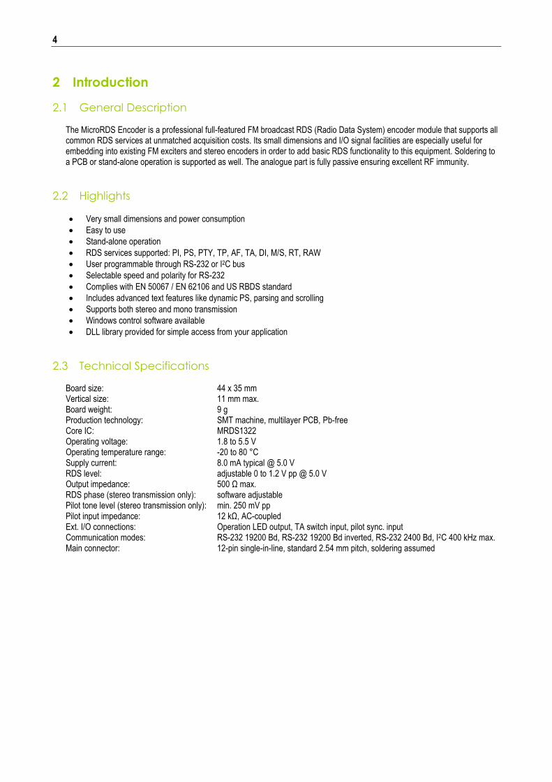
2.3 Technical Specifications
Board size: 44 x 35 mm Vertical size: 11 mm max. Board weight: 9 g Production technology: SMT machine, multilayer PCB, Pb-free Core IC: MRDS1322 Operating voltage: 1.8 to 5.5 V Operating temperature range: -20 to 80 °C Supply current: 8.0 mA typical @ 5.0 V RDS level: adjustable 0 to 1.2 V pp @ 5.0 V Output impedance: 500 Ω max. RDS phase (stereo transmission only): software adjustable Pilot tone level (stereo transmission only): min. 250 mV pp Pilot input impedance: 12 kΩ, AC-coupled Ext. I/O connections: Operation LED output, TA switch input, pilot sync. input Communication modes: RS-232 19200 Bd, RS-232 19200 Bd inverted, RS-232 2400 Bd, I2C 400 kHz max. Main connector: 12-pin single-in-line, standard 2.54 mm pitch, soldering assumed
5
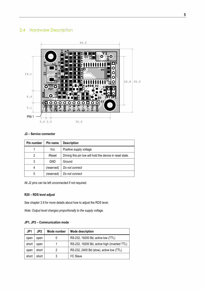
2.4 Hardware Description
2.5 32.03.0
5.1
6.4
19.1
26.8 35.0
44.0
J2 – Service connector
Pin number Pin name Description
1 Vcc Positive supply voltage
2 /Reset Driving this pin low will hold the device in reset state.
3 GND Ground
4 (reserved) Do not connect
5 (reserved) Do not connect
All J2 pins can be left unconnected if not required. R20 – RDS level adjust See chapter 3.9 for more details about how to adjust the RDS level. Note: Output level changes proportionally to the supply voltage.
JP1, JP2 – Communication mode
JP1 JP2 Mode number Mode description
open open 0 RS-232, 19200 Bd, active low (TTL)
short open 1 RS-232, 19200 Bd, active high (inverted TTL)
open short 2 RS-232, 2400 Bd (slow), active low (TTL)
short short 3 I2C Slave
PIN 1
6
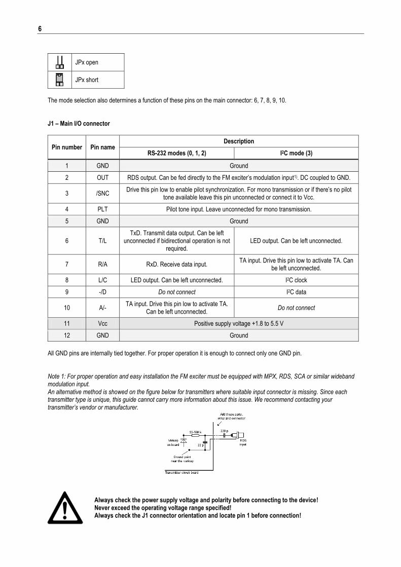
JPx open
JPx short
The mode selection also determines a function of these pins on the main connector: 6, 7, 8, 9, 10.
J1 – Main I/O connector
Pin number Pin name Description
RS-232 modes (0, 1, 2) I2C mode (3)
1 GND Ground
2 OUT RDS output. Can be fed directly to the FM exciter’s modulation input1). DC coupled to GND.
3 /SNC Drive this pin low to enable pilot synchronization. For mono transmission or if there’s no pilot
tone available leave this pin unconnected or connect it to Vcc.
4 PLT Pilot tone input. Leave unconnected for mono transmission.
5 GND Ground
6 T/L TxD. Transmit data output. Can be left
unconnected if bidirectional operation is not required.
LED output. Can be left unconnected.
7 R/A RxD. Receive data input. TA input. Drive this pin low to activate TA. Can
be left unconnected.
8 L/C LED output. Can be left unconnected. I2C clock
9 -/D Do not connect I2C data
10 A/- TA input. Drive this pin low to activate TA.
Can be left unconnected. Do not connect
11 Vcc Positive supply voltage +1.8 to 5.5 V
12 GND Ground
All GND pins are internally tied together. For proper operation it is enough to connect only one GND pin. Note 1: For proper operation and easy installation the FM exciter must be equipped with MPX, RDS, SCA or similar wideband modulation input. An alternative method is showed on the figure below for transmitters where suitable input connector is missing. Since each transmitter type is unique, this guide cannot carry more information about this issue. We recommend contacting your transmitter’s vendor or manufacturer.
Always check the power supply voltage and polarity before connecting to the device! Never exceed the operating voltage range specified! Always check the J1 connector orientation and locate pin 1 before connection!
7
3 Hardware Installation
3.1 The Simplest Serial Connection
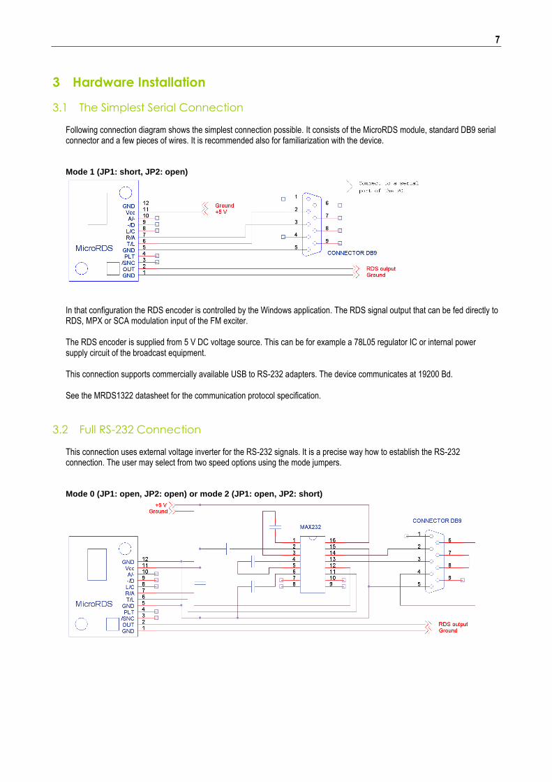
Following connection diagram shows the simplest connection possible. It consists of the MicroRDS module, standard DB9 serial connector and a few pieces of wires. It is recommended also for familiarization with the device. Mode 1 (JP1: short, JP2: open)
In that configuration the RDS encoder is controlled by the Windows application. The RDS signal output that can be fed directly to RDS, MPX or SCA modulation input of the FM exciter. The RDS encoder is supplied from 5 V DC voltage source. This can be for example a 78L05 regulator IC or internal power supply circuit of the broadcast equipment. This connection supports commercially available USB to RS-232 adapters. The device communicates at 19200 Bd. See the MRDS1322 datasheet for the communication protocol specification.
3.2 Full RS-232 Connection This connection uses external voltage inverter for the RS-232 signals. It is a precise way how to establish the RS-232 connection. The user may select from two speed options using the mode jumpers.
Mode 0 (JP1: open, JP2: open) or mode 2 (JP1: open, JP2: short)
8
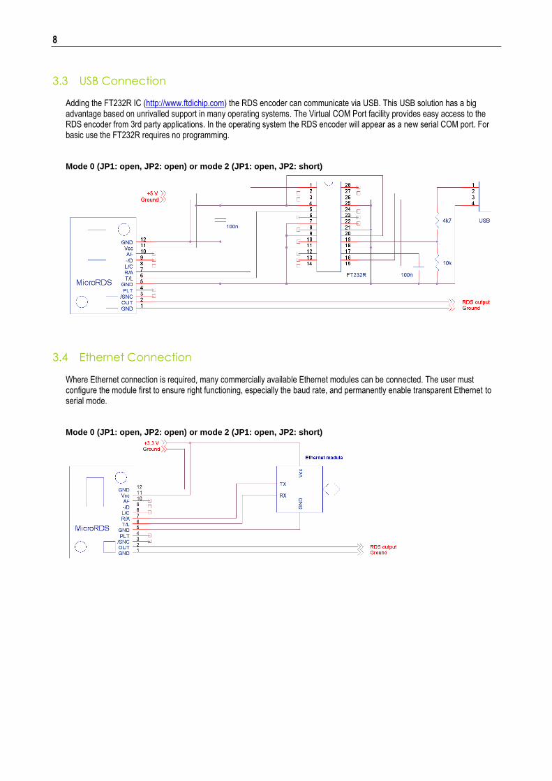
3.3 USB Connection
Adding the FT232R IC (http://www.ftdichip.com) the RDS encoder can communicate via USB. This USB solution has a big advantage based on unrivalled support in many operating systems. The Virtual COM Port facility provides easy access to the RDS encoder from 3rd party applications. In the operating system the RDS encoder will appear as a new serial COM port. For basic use the FT232R requires no programming. Mode 0 (JP1: open, JP2: open) or mode 2 (JP1: open, JP2: short)
3.4 Ethernet Connection
Where Ethernet connection is required, many commercially available Ethernet modules can be connected. The user must configure the module first to ensure right functioning, especially the baud rate, and permanently enable transparent Ethernet to serial mode.
Mode 0 (JP1: open, JP2: open) or mode 2 (JP1: open, JP2: short)
9
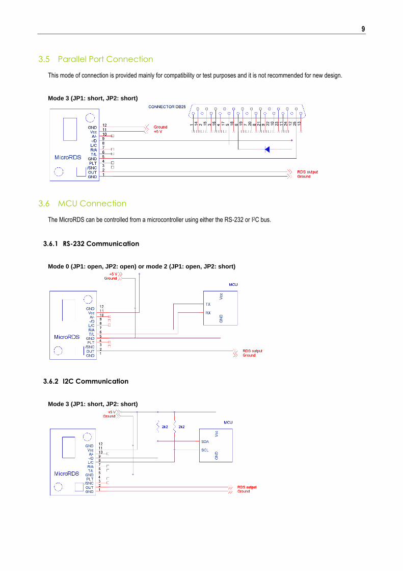
3.5 Parallel Port Connection
This mode of connection is provided mainly for compatibility or test purposes and it is not recommended for new design.
Mode 3 (JP1: short, JP2: short)
3.6 MCU Connection
The MicroRDS can be controlled from a microcontroller using either the RS-232 or I2C bus.
3.6.1 RS-232 Communication
Mode 0 (JP1: open, JP2: open) or mode 2 (JP1: open, JP2: short)
3.6.2 I2C Communication
Mode 3 (JP1: short, JP2: short)
10
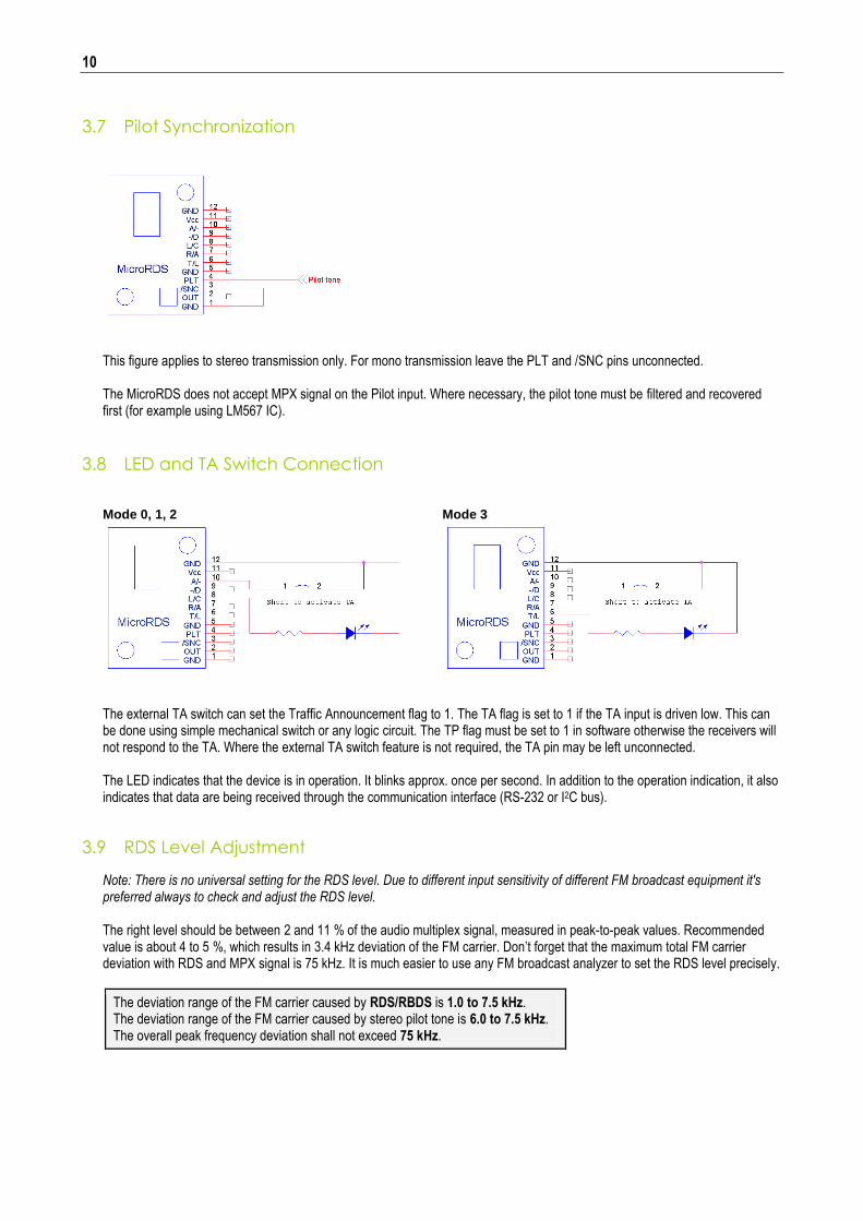
3.7 Pilot Synchronization
This figure applies to stereo transmission only. For mono transmission leave the PLT and /SNC pins unconnected. The MicroRDS does not accept MPX signal on the Pilot input. Where necessary, the pilot tone must be filtered and recovered first (for example using LM567 IC).
3.8 LED and TA Switch Connection
Mode 0, 1, 2 Mode 3
The external TA switch can set the Traffic Announcement flag to 1. The TA flag is set to 1 if the TA input is driven low. This can be done using simple mechanical switch or any logic circuit. The TP flag must be set to 1 in software otherwise the receivers will not respond to the TA. Where the external TA switch feature is not required, the TA pin may be left unconnected.
The LED indicates that the device is in operation. It blinks approx. once per second. In addition to the operation indication, it also indicates that data are being received through the communication interface (RS-232 or I2C bus).
3.9 RDS Level Adjustment
Note: There is no universal setting for the RDS level. Due to different input sensitivity of different FM broadcast equipment it's preferred always to check and adjust the RDS level. The right level should be between 2 and 11 % of the audio multiplex signal, measured in peak-to-peak values. Recommended value is about 4 to 5 %, which results in 3.4 kHz deviation of the FM carrier. Don’t forget that the maximum total FM carrier deviation with RDS and MPX signal is 75 kHz. It is much easier to use any FM broadcast analyzer to set the RDS level precisely.
The deviation range of the FM carrier caused by RDS/RBDS is 1.0 to 7.5 kHz. The deviation range of the FM carrier caused by stereo pilot tone is 6.0 to 7.5 kHz. The overall peak frequency deviation shall not exceed 75 kHz.
11
4 Software Installation
4.1 Windows Control Software 1. To install the Windows control software called ‘Tiny RDS’, run the setup exe file and go through the simple installation
wizard.
2. In the case of USB connection install the USB driver now. Pure RS-232 connection requires no driver.
3. Make sure the RDS encoder is connected and powered, all connectors are seated completely and where possible, use screws to fix the connection. The software supports connection as drawn in chapter 3.1, 3.2, 3.3 or 3.5.
4. Run the Tiny RDS software using Windows Start button.
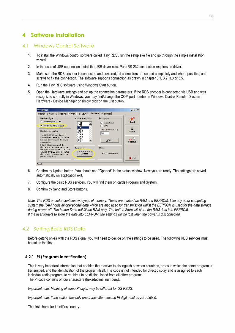
5. Open the Hardware settings and set up the connection parameters. If the RDS encoder is connected via USB and was recognized correctly in Windows, you may find/change the COM port number in Windows Control Panels - System - Hardware - Device Manager or simply click on the List button.
6. Confirm by Update button. You should see "Opened" in the status window. Now you are ready. The settings are saved automatically on application exit.
7. Configure the basic RDS services. You will find them on cards Program and System.
8. Confirm by Send and Store buttons.
Note: The RDS encoder contains two types of memory. These are marked as RAM and EEPROM. Like any other computing system the RAM holds all operational data which are also used for transmission whilst the EEPROM is used for the data storage during power-off. The button Send will fill the RAM only. The button Store will store the RAM data into EEPROM. If the user forgets to store the data into EEPROM, the settings will be lost when the power is disconnected.
4.2 Setting Basic RDS Data Before getting on-air with the RDS signal, you will need to decide on the settings to be used. The following RDS services must be set as the first.
4.2.1 PI (Program Identification) This is very important information that enables the receiver to distinguish between countries, areas in which the same program is transmitted, and the identification of the program itself. The code is not intended for direct display and is assigned to each individual radio program, to enable it to be distinguished from all other programs. The PI code consists of four characters (hexadecimal numbers). Important note: Meaning of some PI digits may be different for US RBDS. Important note: If the station has only one transmitter, second PI digit must be zero (x0xx). The first character identifies country:
12
0 Cannot be assigned! 8 PS, BG, LV, PT
1 DE, GR, MA, IE, MD 9 AL, DK, LI, LB, SI
2 DZ, CY, CZ, TR, EE A AT, GI, IS
3 AD, SM, PL, MK B HU, IQ, MC, HR
4 IL,CH, VA C MT, GB, LT
5 IT, JO, SK D DE, LY, YU
6 BE, FI, SY, UA E RO, ES, SE
7 RU, LU, TN, NL F EG, FR, NO, BY, BA
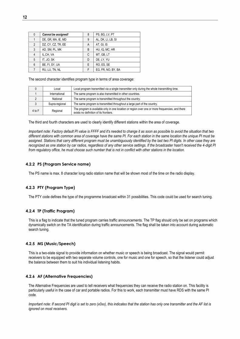
The second character identifies program type in terms of area coverage:
0 Local Local program transmitted via a single transmitter only during the whole transmitting time.
1 International The same program is also transmitted in other countries.
2 National The same program is transmitted throughout the country.
3 Supra-regional The same program is transmitted throughout a large part of the country.
4 to F Regional The program is available only in one location or region over one or more frequencies, and there exists no definition of its frontiers.
The third and fourth characters are used to clearly identify different stations within the area of coverage. Important note: Factory default PI value is FFFF and it's needed to change it as soon as possible to avoid the situation that two different stations with common area of coverage have the same PI. For each station in the same location the unique PI must be assigned. Stations that carry different program must be unambiguously identified by the last two PI digits. In other case they are recognized as one station by car radios, regardless of any other service settings. If the broadcaster hasn't received the 4-digit PI from regulatory office, he must choose such number that is not in conflict with other stations in the location.
4.2.2 PS (Program Service name) The PS name is max. 8 character long radio station name that will be shown most of the time on the radio display.
4.2.3 PTY (Program Type) The PTY code defines the type of the programme broadcast within 31 possibilities. This code could be used for search tuning.
4.2.4 TP (Traffic Program) This is a flag to indicate that the tuned program carries traffic announcements. The TP flag should only be set on programs which dynamically switch on the TA identification during traffic announcements. The flag shall be taken into account during automatic search tuning.
4.2.5 MS (Music/Speech) This is a two-state signal to provide information on whether music or speech is being broadcast. The signal would permit receivers to be equipped with two separate volume controls, one for music and one for speech, so that the listener could adjust the balance between them to suit his individual listening habits.
4.2.6 AF (Alternative Frequencies) The Alternative Frequencies are used to tell receivers what frequencies they can receive the radio station on. This facility is particularly useful in the case of car and portable radios. For this to work, each transmitter must have RDS with the same PI code. Important note: If second PI digit is set to zero (x0xx), this indicates that the station has only one transmitter and the AF list is ignored on most receivers.
13
4.3 Software Troubleshooting The RDS encoder uses simple connection and has been designed to make its use as easy and painless as possible. However, success depends upon several settings and things working together correctly. While correcting problems is usually quite simple, the difficulty lays in knowing where to look. This section is designed to assist you in determining the cause of problems that may occur when establishing a communication with the PC software, so they can be fixed quickly.
4.3.1 How to verify the connection with the RDS encoder? In case of some troubles it may be important to check if the RDS encoder receives data from the computer. The easiest way how to check the connection is clicking on the "Read Status" button on "System" card in the Windows software. Correct connection will result in pop-up a message window whereas incorrect connection is indicated only by a "!Ready" message in the bottom line of the application. Note that "Bidirectional" option must be enabled on "Hardware" card for this test.
4.3.2 What to check if the connection does not work?
Is the RDS encoder really connected to the port selected? Typically there are more ports installed in the system (modem, mobile phone, IrDA port, bluetooth etc.) - opening of these ports is usually possible, however it will result in no success. User should ensure that the serial port desired is enabled in BIOS Setup. No other configuration of the port is required, the software does that itself.
Is the RDS encoder connected to a power supply? Connecting a power supply is required prior to communicating with the unit.
Is there right Communication mode selected on the encoder? The communication mode can be selected via jumpers JP1 and JP2. See appropriate connection drawing for proper jumper settings. A power off/on cycle is required after changing the jumper position.
Is there right communication speed selected in the software? The speed can be selected on "Hardware" card, by item "Slow". Enabling this item, the encoder is expected to communicate on 2400 bps (mode 2), otherwise 19200 bps is expected (mode 0 and 1).
Is there right hardware type selected in the software? The software supports two types of hardware. Make sure the MicroRDS/MRDS1322 device is selected on "Hardware" card.
Is the serial cable wired right? Especially RxD pin of the RDS encoder must be connected to TxD pin of the computer and vice versa. Mistaking of these wires will result in no communication.
Note that there are some serial ports (maybe 1 % of all) that do not accept the connection drawn in chapter 3.1 due to negative voltage required on their RxD pin. This applies mainly to very old computers. User can still send data via this port but cannot receive anything. The solution for these ports is a full-featured serial connection as drawn in chapter 3.2.
14
5 Annexes
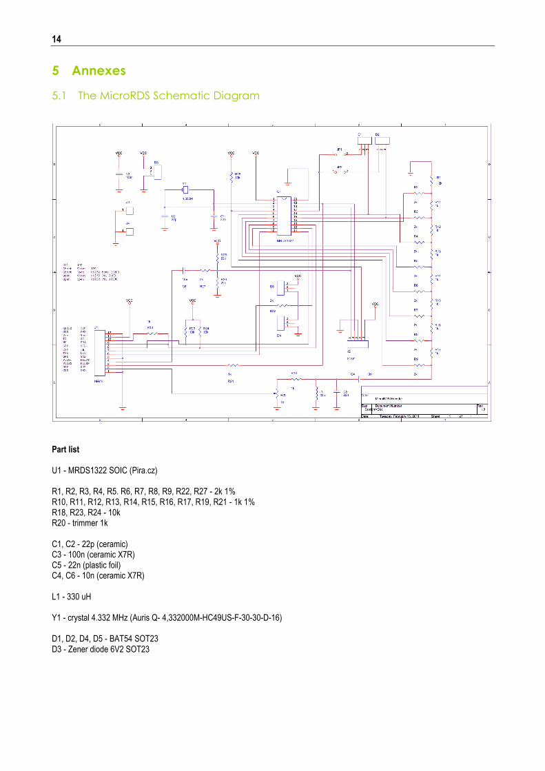
5.1 The MicroRDS Schematic Diagram
Part list U1 - MRDS1322 SOIC (Pira.cz) R1, R2, R3, R4, R5. R6, R7, R8, R9, R22, R27 - 2k 1% R10, R11, R12, R13, R14, R15, R16, R17, R19, R21 - 1k 1% R18, R23, R24 - 10k R20 - trimmer 1k C1, C2 - 22p (ceramic) C3 - 100n (ceramic X7R) C5 - 22n (plastic foil) C4, C6 - 10n (ceramic X7R) L1 - 330 uH Y1 - crystal 4.332 MHz (Auris Q- 4,332000M-HC49US-F-30-30-D-16) D1, D2, D4, D5 - BAT54 SOT23 D3 - Zener diode 6V2 SOT23
15
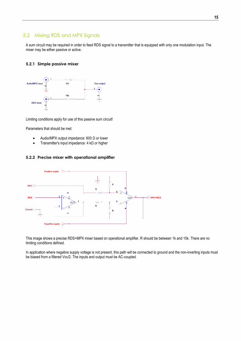
5.2 Mixing RDS and MPX Signals
A sum circuit may be required in order to feed RDS signal to a transmitter that is equipped with only one modulation input. The mixer may be either passive or active.
5.2.1 Simple passive mixer
Limiting conditions apply for use of this passive sum circuit! Parameters that should be met:
Audio/MPX output impedance: 600 Ω or lower
Transmitter's input impedance: 4 kΩ or higher
5.2.2 Precise mixer with operational amplifier
This image shows a precise RDS+MPX mixer based on operational amplifier. R should be between 1k and 10k. There are no limiting conditions defined. In application where negative supply voltage is not present, this path will be connected to ground and the non-inverting inputs must be biased from a filtered Vcc/2. The inputs and output must be AC-coupled.