
Metric Bolts in a Mixed -Metric Plant 3D Project · 2019-01-16 · Metric Bolts in a Mixed ......
6
White Paper Reference: Sept 2017 Guide by Andy Davis 01784 419 922 www.cadline.co.uk [email protected] Page 1 of 6 Metric Bolts in a Mixed-Metric Plant 3D Project AutoCAD Plant 3D 2018 The standard bolt lengths used for ANSI fittings in AutoCAD Plant 3D are defined using an Imperial Bolt Mapping Standard. When using the default isometric styles in mixed-metric projects the bolt sizes and lengths contained within the ASME catalogues and specs produce a BOM showing imperial bolt diameters with metric lengths, often rounded to inappropriate values. The default isometric styles always display bolt diameters in imperial units for mixed-metric projects and always display lengths in metric units. The values in the PipelinesSettings.xml file are not observed and bolt diameters are read from the Imperial value in the BoltSizeMappings.xml file. However, with a little non-standard setup and configuration, it is possible to implement fully metric bolt sizes in a mixed-metric project. In the following discussion we will explore how we might do this. Bolt Set The first thing we need to do is to create a metric bolt set that we can use in our mixed-metric project. This will be defined in the Catalog Editor with Inch nominal units, as we will be using this bolt set with ANSI fittings. However, we will specify metric bolt sizes and bolt lengths to comply with our standard bolt lengths. Unfortunately, because we must specify Inch nominal units for our bolt set, we must use an Imperial bolt mapping standard to define our standard bolt lengths and this is the root of most bolt length issues in mixed-metric projects. To define the bolt mapping standard we must convert our metric lengths to inches by dividing by 25.4.
Transcript of Metric Bolts in a Mixed -Metric Plant 3D Project · 2019-01-16 · Metric Bolts in a Mixed ......

White Paper Reference: Sept 2017
Guide by Andy Davis
01784 419 922 www.cadline.co.uk [email protected]
Page 1 of 6
Metric Bolts in a Mixed-Metric Plant 3D Project
AutoCAD Plant 3D 2018
The standard bolt lengths used for ANSI fittings in AutoCAD Plant 3D are defined using an Imperial Bolt Mapping
Standard. When using the default isometric styles in mixed-metric projects the bolt sizes and lengths contained within
the ASME catalogues and specs produce a BOM showing imperial bolt diameters with metric lengths, often rounded
to inappropriate values.
The default isometric styles always display bolt diameters in imperial units for mixed-metric projects and always
display lengths in metric units. The values in the PipelinesSettings.xml file are not observed and bolt diameters are
read from the Imperial value in the BoltSizeMappings.xml file.
However, with a little non-standard setup and configuration, it is possible to implement fully metric bolt sizes in a
mixed-metric project. In the following discussion we will explore how we might do this.
Bolt Set
The first thing we need to do is to create a metric bolt set that we can use in our mixed-metric project. This will be
defined in the Catalog Editor with Inch nominal units, as we will be using this bolt set with ANSI fittings. However, we
will specify metric bolt sizes and bolt lengths to comply with our standard bolt lengths.
Unfortunately, because we must specify Inch nominal units for our bolt set, we must use an Imperial bolt mapping
standard to define our standard bolt lengths and this is the root of most bolt length issues in mixed-metric projects.
To define the bolt mapping standard we must convert our metric lengths to inches by dividing by 25.4.

White Paper Reference: Sept 2017
Guide by Andy Davis
01784 419 922 www.cadline.co.uk [email protected]
Page 2 of 6
In the “Metric Std” bolt mapping standard shown above we have converted into inches bolt lengths from 50mm to
250mm at 5mm increments.
We will assign our “Metric Std” bolt mapping standard to our bolt set and then specify the default lengths for our
bolts, not forgetting to enter the corresponding Flange Thickness.

White Paper Reference: Sept 2017
Guide by Andy Davis
01784 419 922 www.cadline.co.uk [email protected]
Page 3 of 6
Note: we must set the Is Lug Set flag to true and then back to false when we create our bolt set, otherwise the value may be set to NULL when we add the bolt to a spec – this would cause the default Flanged joint connection setting to fail in Plant 3D resulting in Placeholder bolts being inserted.
When we specify the bolt lengths we will use metric units to enter the values.
The lengths we enter will correspond to our standard bolt lengths for the given flange thickness, see the example
below.
White Paper Reference: Sept 2017
Guide by Andy Davis
01784 419 922 www.cadline.co.uk [email protected]
Page 4 of 6
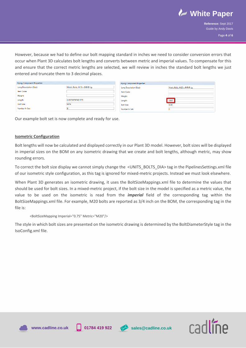
However, because we had to define our bolt mapping standard in inches we need to consider conversion errors that
occur when Plant 3D calculates bolt lengths and converts between metric and imperial values. To compensate for this
and ensure that the correct metric lengths are selected, we will review in inches the standard bolt lengths we just
entered and truncate them to 3 decimal places.
Our example bolt set is now complete and ready for use.
Isometric Configuration
Bolt lengths will now be calculated and displayed correctly in our Plant 3D model. However, bolt sizes will be displayed
in imperial sizes on the BOM on any isometric drawing that we create and bolt lengths, although metric, may show
rounding errors.
To correct the bolt size display we cannot simply change the <UNITS_BOLTS_DIA> tag in the PipelinesSettings.xml file
of our isometric style configuration, as this tag is ignored for mixed-metric projects. Instead we must look elsewhere.
When Plant 3D generates an isometric drawing, it uses the BoltSizeMappings.xml file to determine the values that
should be used for bolt sizes. In a mixed-metric project, if the bolt size in the model is specified as a metric value, the
value to be used on the isometric is read from the imperial field of the corresponding tag within the
BoltSizeMappings.xml file. For example, M20 bolts are reported as 3/4 inch on the BOM, the corresponding tag in the
file is:
<BoltSizeMapping Imperial="0.75" Metric="M20"/>
The style in which bolt sizes are presented on the isometric drawing is determined by the BoltDiameterStyle tag in the
IsoConfig.xml file.

White Paper Reference: Sept 2017
Guide by Andy Davis
01784 419 922 www.cadline.co.uk [email protected]
Page 5 of 6
IsoConfig.xml file
In the example above, we see the default Style tags for a mixed-metric project. Bolt diameters are displayed using the
ImperialSize style. So, if we were to create a new style, we could convert the bolt sizes back to metric values again.
We will define the following style tag to convert our imperial bolts sizes back to metric values with an “M” prefix:
<Style Name="MetricBoltSize" UnitFormat="Decimal" Precision="Precision1" Prefix="M" Suffix="" Scale="25.4" Decimal="." />
and assign this to the Imperial field of the BoltDiameterStyle tag.
Unfortunately, simply converting the imperial bolt sizes to metric does not produce standard metric bolt sizes.
However, we can fix this by modifying the imperial values in the BoltSizeMappings.xml file to be the exact metric bolt
diameters divided by 25.4 as shown in the example below:
BoltSizeMappings.xml File
We have now configured the isometric to display metric bolt sizes. All that remains is to fix any rounding errors that
may occur with the bolt lengths, and we can do this by simply setting the value of the Rounded field to “false” in the
BoltLengthStyle tag in our IsoConfig.xml file.
The example below shows all of the changes we have made to our IsoConfig.xml file.

White Paper Reference: Sept 2017
Guide by Andy Davis
01784 419 922 www.cadline.co.uk [email protected]
Page 6 of 6
IsoConfig.xml File
The following simple example shows our metric bolt set in use in a mixed-metric project, three flange sets have been
modelled as shown at different sizes.
Plant 3D Model
The isometric drawing and corresponding BOM produced are shown below.
Isometric drawing plus BOM