Method for Powering Arduino Microcontroller and Shield ...€¦ · Method for Powering Arduino...
7
Method for Powering Arduino Microcontroller and Shield using a Battery By: Drew Newell 3-30-12 Abstract: This note describes a method of using a LM117 regulator to power the Arduino platform using a deep cycle battery. The design assumes high voltage and ambient temperatures which results in a flexible and robust design. Chassis requirements are also described.
Transcript of Method for Powering Arduino Microcontroller and Shield ...€¦ · Method for Powering Arduino...

Method for Powering Arduino Microcontroller
and Shield using a Battery
By: Drew Newell
3-30-12
Abstract: This note describes a method of using a LM117 regulator to power the Arduino
platform using a deep cycle battery. The design assumes high voltage and ambient temperatures
which results in a flexible and robust design. Chassis requirements are also described.

Introduction and Objectives
The main objective of this application note is to describe a method of powering an Arduino
microcontroller using a battery. Additionally, the power requirements of peripheral hardware, in
this case a GSM shield, were taken into account when designing this supply. This flexibility
incorporated into the design allows this power supply to be used in most any Arduino/Shield
application.
Identification of Power Requirements
Through experimentation, the Arduino with GSM shield were found to draw 500mA with a peak
draw of 1.5A on the rare occasions when the shield is first trying to establish connection to the
network. A deep cycle 12V battery was used as a power supply (simulated using a wall power
supply). Due to low power demands, a LM117 voltage regulator can be used.
Typical (A) Max (A)
Arduino/GSM Shield 0.5 1.5
LM117 1.5 2.2

Below is the PSPICE verification of the circuit design.
LM117 ARDUINO POWER SUPPLY
VBAT 1 0 12
C1 1 0 0.1U
X1 1 2 3 LM117HV
R1 2 3 270
R2 3 0 810
RL 2 0 10
C2 2 0 1U
.SUBCKT LM117HV 1 2 3
* IN OUT ADJ
RB1 7 6 1
RB2 6 5 124
RBC 15 5 247
RC 1 14 0.742
RI 2 4 100MEG
RP 9 8 100
RZ 8 10 .104
CBC 13 15 2.479N
CPZ 10 2 0.796U
DBK 14 13 DLM117HV
DFB 6 12 DLM117HV
DSC 6 11 DLM117HV
EB 7 2 8 2 1
EFB 12 2 POLY(2) (13,5) (6,5) 3.52 -135M 0 1.21M -107.9M
EP 9 2 4 2 265.5
ESC 11 2 POLY(2) (13,5) (6,5) 2.45 0 0 0 -107.9M
IADJ 1 4 48.4U
QP 13 5 2 QLM117HV
VREF 4 3 1.2782
.MODEL QLM117HV NPN (IS=30F BF=50 VAF=9.27 NF=1.604)
.MODEL DLM117HV D (IS=30F N=1.604)
.ENDS LM117HV
.TRAN .1U 16U 0 .01U
.PROBE
.END

With adjustment of the potentiometer in the circuit, an output voltage of exactly 5V can be
achieved.
Heat Sink Considerations
The high end of the typical current draw from the Arduino and shield combination is 500mA.
During periods where a battery may be charging, a 12V deep cycle battery can have a voltage in
the range of 14V. Using these stipulations as worse case scenarios, the power dissipated by the
LM117 can be calculated. Additionally, assuming that a worse case ambient temperature of 32 C
can be obtained, the equivalent thermal resistance of the LM117 can be calculated. The TO-220
package was used for the below calculations.
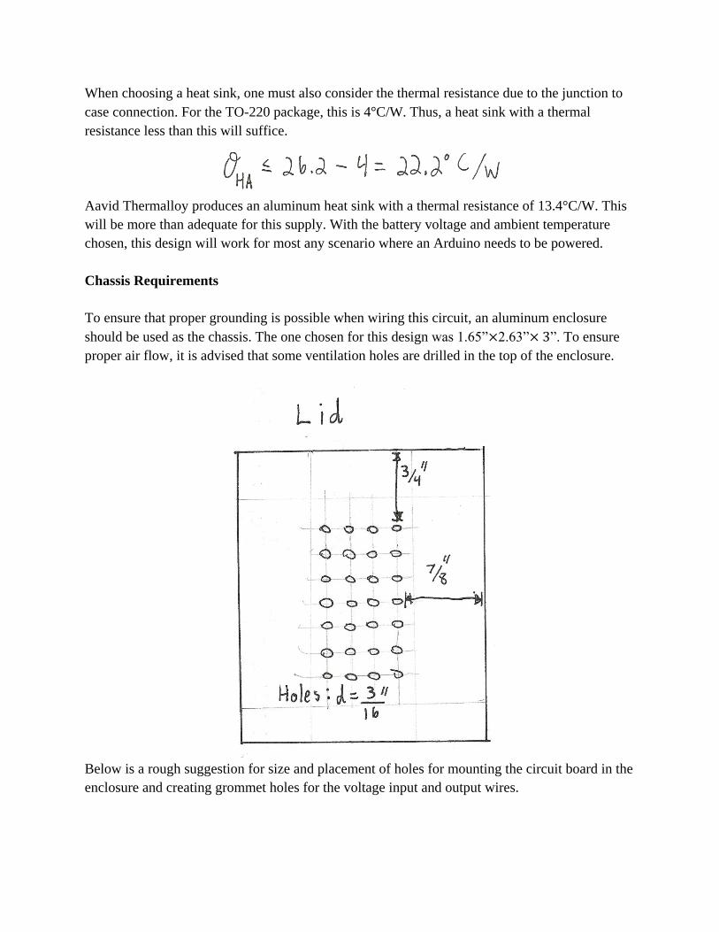
When choosing a heat sink, one must also consider the thermal resistance due to the junction to
case connection. For the TO-220 package, this is 4 C/W. Thus, a heat sink with a thermal
resistance less than this will suffice.
Aavid Thermalloy produces an aluminum heat sink with a thermal resistance of 13.4°C/W. This
will be more than adequate for this supply. With the battery voltage and ambient temperature
chosen, this design will work for most any scenario where an Arduino needs to be powered.
Chassis Requirements
To ensure that proper grounding is possible when wiring this circuit, an aluminum enclosure
should be used as the chassis. The one chosen for this design was 1.65” 2.63” ”. To ensure
proper air flow, it is advised that some ventilation holes are drilled in the top of the enclosure.
Below is a rough suggestion for size and placement of holes for mounting the circuit board in the
enclosure and creating grommet holes for the voltage input and output wires.

Evaluation
After running the circuit for several runs of an hour or more, no appreciable accumulation of heat
was observed. The ventilation holes placed in the chassis will allow for enough natural airflow to
cool the circuit. At the time of writing this note, a full 8 hour run at an ambient temperature of
32°C was not possible but the supply should operate correctly given the theoretical verification
described above.

References
[1] Texas Instruments. (Feb. 25, 2011). LM117/LM317A/LM317 3-Terminal Adjustable
Regulator.
http://www.ti.com/general/docs/lit/getliterature.tsp?genericPartNumber=lm117®=en&fileTyp
e=pdf
[2] Perez, Richard. (1993). Lead-Acid Battery State of Charge vs.Voltage.
http://www.scubaengineer.com/documents/lead_acid_battery_charging_graphs.pdf