MESP 040300-01 SUBSTATION AUTOMATIC ... and control gear for voltages above 1 kV and up to and...
24
PRINTOUT MAY NOT BE UP-TO-DATE; REFER TO METRO INTRANET FOR THE LATEST VERSION Electrical Networks Specification Engineering MESP 040300-01 SUBSTATION AUTOMATIC, CONTROLLED AND INDICATED, FIXED MOUNTED SWITCHGEAR FOR ESSENTIAL SERVICES OR SIGNAL POWER PURPOSES Version: 1 Issued: September 2016 Owner: Head of Engineering - Electrical Approved By: Andrew Russack Head of Engineering - Electrical
Transcript of MESP 040300-01 SUBSTATION AUTOMATIC ... and control gear for voltages above 1 kV and up to and...

PRINTOUT MAY NOT BE UP-TO-DATE; REFER TO METRO INTRANET FOR THE LATEST VERSION
Electrical Networks Specification
Engineering
MESP 040300-01
SUBSTATION AUTOMATIC, CONTROLLED AND INDICATED, FIXED MOUNTED SWITCHGEAR FOR
ESSENTIAL SERVICES OR SIGNAL POWER PURPOSES
Version: 1
Issued: September 2016
Owner: Head of Engineering - Electrical
Approved By:
Andrew Russack
Head of Engineering - Electrical

ELECTRICAL NETWORKS SPECIFICATION SUBSTATION AUTOMATIC, CONTROLLED AND INDICATED,
FIXED MOUNTED SWITCHGEAR FOR ESSENTIAL SERVICES OR SIGNAL POWER PURPOSES
MESP 040300-01 Version: 1 Effective from: 23rd September 2016
L1-CHE-SPE-177
Approving Manager: Head of Engineering - Electrical Approval Date: 23/09/2016 Next Review Date: 23/09/2019 PRINTOUT MAY NOT BE UP-TO-DATE; REFER TO METRO INTRANET FOR THE LATEST VERSION Page 2 of 24
Approval
Amendment Record
Approval Date Version Description
23/09/2016 1 Supersedes L1-CHE-SPE-015. Minor clarifications throughout. Generalisation to include 3.3kV systems.
ELECTRICAL NETWORKS SPECIFICATION SUBSTATION AUTOMATIC, CONTROLLED AND INDICATED,
FIXED MOUNTED SWITCHGEAR FOR ESSENTIAL SERVICES OR SIGNAL POWER PURPOSES
MESP 040300-01 Version: 1 Effective from: 23rd September 2016
L1-CHE-SPE-177
Approving Manager: Head of Engineering - Electrical Approval Date: 23/09/2016 Next Review Date: 23/09/2019 PRINTOUT MAY NOT BE UP-TO-DATE; REFER TO METRO INTRANET FOR THE LATEST VERSION Page 3 of 24
Table of Contents Purpose .............................................................................................................................. 5 1. Scope ................................................................................................................................. 5 2. Abbreviation ...................................................................................................................... 5 3. Definitions .......................................................................................................................... 5 4. References & Legislations ................................................................................................ 5 5. Application ......................................................................................................................... 6 6. Functionality ...................................................................................................................... 6 7. Operating Conditions ........................................................................................................ 8 8.
Service Conditions ............................................................................................................... 8 8.1
Electrical Conditions ............................................................................................................ 8 8.2
Ratings ............................................................................................................................... 9 9. Functional Components Requirements ......................................................................... 11 10.
Circuit Breaker Functional Component .............................................................................. 11 10.1
Load Break Switch Functional Component ....................................................................... 11 10.2
Earth Switch / Disconnector Functional Component ......................................................... 11 10.3
Busbar Functional Component .......................................................................................... 12 10.4
Bus Indication Unit Functional Component ....................................................................... 12 10.5
Power Cable Termination Functional Component ............................................................. 13 10.6
Phase Test and Line Alive Functional Component ........................................................... 14 10.7
Control and Protection Functional Component ................................................................. 14 10.8
Interlocking Requirements.............................................................................................. 15 11. Functional Unit Interlocking Requirements ........................................................................ 15 11.1
Wiring ............................................................................................................................... 16 12. Accessories ..................................................................................................................... 16 13.
Marking and Labelling ........................................................................................................ 16 13.1
Anti-condensation Heaters ................................................................................................ 16 13.2
Prohibited Materials ........................................................................................................... 17 13.3
Arc Venting ...................................................................................................................... 17 14. Testing ............................................................................................................................. 17 15.
Type Test ........................................................................................................................... 17 15.1
Routine Tests ..................................................................................................................... 17 15.2
Spares .............................................................................................................................. 17 16. Documentation and Support ........................................................................................... 17 17.
Documentation Requirements ........................................................................................... 18 17.1
Drawing Format ................................................................................................................. 18 17.2
ELECTRICAL NETWORKS SPECIFICATION SUBSTATION AUTOMATIC, CONTROLLED AND INDICATED,
FIXED MOUNTED SWITCHGEAR FOR ESSENTIAL SERVICES OR SIGNAL POWER PURPOSES
MESP 040300-01 Version: 1 Effective from: 23rd September 2016
L1-CHE-SPE-177
Approving Manager: Head of Engineering - Electrical Approval Date: 23/09/2016 Next Review Date: 23/09/2019 PRINTOUT MAY NOT BE UP-TO-DATE; REFER TO METRO INTRANET FOR THE LATEST VERSION Page 4 of 24
Technical Maintenance Plan ............................................................................................. 18 17.3
Maintenance Manual ......................................................................................................... 18 17.4
Installation Instructions Manual ......................................................................................... 19 17.5
Operating Instructions Manual ........................................................................................... 19 17.6
Training .............................................................................................................................. 19 17.7
Tools & Equipment ............................................................................................................ 19 17.8
Design Management Requirements ............................................................................... 19 18. Tender Submission ............................................................................................................ 20 18.1
Contract Documentation .................................................................................................... 20 18.2
Pre-Delivery Documentation .............................................................................................. 20 18.3
Information to be Supplied by Tenderers ...................................................................... 21 19.
ELECTRICAL NETWORKS SPECIFICATION SUBSTATION AUTOMATIC, CONTROLLED AND INDICATED,
FIXED MOUNTED SWITCHGEAR FOR ESSENTIAL SERVICES OR SIGNAL POWER PURPOSES
MESP 040300-01 Version: 1 Effective from: 23rd September 2016
L1-CHE-SPE-177
Approving Manager: Head of Engineering - Electrical Approval Date: 23/09/2016 Next Review Date: 23/09/2019 PRINTOUT MAY NOT BE UP-TO-DATE; REFER TO METRO INTRANET FOR THE LATEST VERSION Page 5 of 24
Purpose 1.This document is the MTM technical specification for automatic and fixed mounted switchgear, which is remotely controlled and indicated for use at Substations for switching and protection of the Railway Essential Service Power Distribution System.
Scope 2.The scope of this document applies to the supply of new switchgear, for use in a new Substation and for renewals of existing installations.
The scope of supply shall include design, manufacture, assembly and testing of the equipment.
This specification is to be read in conjunction with a supplied Scope of Works document, which details quantities of each functional unit and any other special requirements.
This specification is for fixed mounted switchgear. If a withdrawable version is to be offered, it will be considered providing it meets the technical requirements and the particular needs of the work site.
Abbreviation 3.MTM - Metro Trains Melbourne
SCADA - Supervisory, Control and Data Acquisition
Definitions 4.For the purpose of this specification, the terms, definitions and abbreviated terms in AS 1852.441 apply.
References & Legislations 5.AS 1939 – 1990 Classification of Degrees of Protection Provided by Enclosures for
Electrical Equipment
AS 62271.100 – 2008 High Voltage Switchgear and Control gear – High Voltage Alternating Current Circuit Breakers
AS 62271.102 – 2008 High Voltage Switchgear and Control gear – Alternating Current Disconnectors and Earthing Switches
AS 62271.200 – 2005 High Voltage switchgear and control gear – A.C metal enclosed switchgear and control gear for voltages above 1 kV and up to and including 52 kV
AS 60044 – 2007 Instrument Transformers
Reference to all standards shall be read as a reference to the latest edition of that standard and amendments available at the time of tendering.
ELECTRICAL NETWORKS SPECIFICATION SUBSTATION AUTOMATIC, CONTROLLED AND INDICATED,
FIXED MOUNTED SWITCHGEAR FOR ESSENTIAL SERVICES OR SIGNAL POWER PURPOSES
MESP 040300-01 Version: 1 Effective from: 23rd September 2016
L1-CHE-SPE-177
Approving Manager: Head of Engineering - Electrical Approval Date: 23/09/2016 Next Review Date: 23/09/2019 PRINTOUT MAY NOT BE UP-TO-DATE; REFER TO METRO INTRANET FOR THE LATEST VERSION Page 6 of 24
All materials and components shall comply with the requirements of the relevant Australian Standards, or where these do not exist, with the International Electro-technical Commission (IEC) Standards.
Application 6.The MTM Traction Substations primarily convert electricity from High Voltage AC to 1500 Volt DC power for the operation of the Electric Train System in Melbourne. MTM Substations also convert 22kV to either 2.2 kV signal power network or 3.3 kV Essential Services Distribution System which supplies power along the Rail Corridor for essential services.
The system may be either a single phase, 50Hz, 2 wire unearthed system at 2.2kV, or a three phase three wire system at 3.3kV, in accordance with L1-CHE-SPE-154, 3.3kV Essential Services Distribution System.
Functionality 7.The switchgear configuration shall consist of functional units to provide the required functionality at the subject installation. Each functional unit will be housed within one panel of the switchboard assembly.
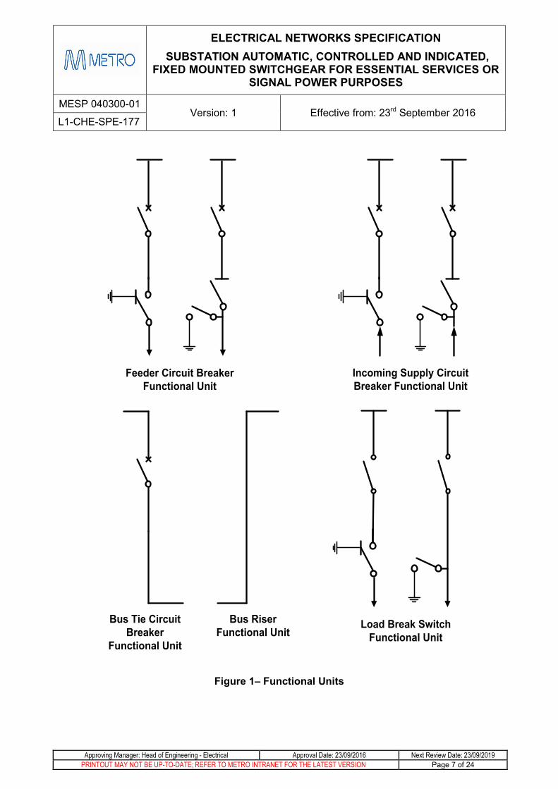
The main functional units for Essential Service Power Distribution (refer Figure 1) are:
• Circuit Breaker Functional Unit which may be one of:
o Feeder Circuit Breaker Unit
o Incoming Supply Circuit Breaker Unit
o Bus Tie Circuit Breaker Unit
• Load Break Switch Functional Unit
• Bus Riser Functional Unit
The specific switchgear configuration shall be provided in the Scope of Works document.
Each of the functional units can comprise of a combination of the following functional components:
• Circuit Breaker
• Earth Switch
• Load Break Switch
• Bus Indication Unit
• Busbar
• Power Cable Termination Compartment
• Control and Protection
• Phase Test / Line Alive (Typically consists of LEDs, using capacitive coupling and insertion plugs)
ELECTRICAL NETWORKS SPECIFICATION SUBSTATION AUTOMATIC, CONTROLLED AND INDICATED,
FIXED MOUNTED SWITCHGEAR FOR ESSENTIAL SERVICES OR SIGNAL POWER PURPOSES
MESP 040300-01 Version: 1 Effective from: 23rd September 2016
L1-CHE-SPE-177
Approving Manager: Head of Engineering - Electrical Approval Date: 23/09/2016 Next Review Date: 23/09/2019 PRINTOUT MAY NOT BE UP-TO-DATE; REFER TO METRO INTRANET FOR THE LATEST VERSION Page 7 of 24
Feeder Circuit Breaker Functional Unit
Incoming Supply Circuit Breaker Functional Unit
Bus Tie Circuit Breaker
Functional Unit
Bus Riser Functional Unit
Load Break Switch Functional Unit
Figure 1– Functional Units

ELECTRICAL NETWORKS SPECIFICATION SUBSTATION AUTOMATIC, CONTROLLED AND INDICATED,
FIXED MOUNTED SWITCHGEAR FOR ESSENTIAL SERVICES OR SIGNAL POWER PURPOSES
MESP 040300-01 Version: 1 Effective from: 23rd September 2016
L1-CHE-SPE-177
Approving Manager: Head of Engineering - Electrical Approval Date: 23/09/2016 Next Review Date: 23/09/2019 PRINTOUT MAY NOT BE UP-TO-DATE; REFER TO METRO INTRANET FOR THE LATEST VERSION Page 8 of 24
Table 1 – Functional Components
Functional Unit Circuit Breaker Load Break Switch
Bus Riser Functional
Component Feeder Incoming
Supply Bus Tie
Circuit Breaker Y Y Y N N Load Break
Switch N N N Y N
Earth Switch / Disconnector Y Y N Y N
Bus Indication Unit N Y N N N
Power Cable Termination Y Y N Y N
Control Y Y Y N N Protection Y Y N N N
Phase Test & Line Alive Line side Supply Side One side Line Side N
Busbar Y Y Y Y Y
Operating Conditions 8.
Service Conditions 8.1The switchboard panels will be installed indoors on a rigid floor in a building. It is preferred that cables from below enter the switchboard from a pit.
The switchboard panels may be required to be installed on a raised metallic plinth for easy cable entry into the Power Cable Termination Compartment. The height of the plinth will be dependent on site conditions and will be specified in the scope of works document.
Each panel shall have an earthing bar and provision shall be made to connect each panel on the switchboard to this bar. The linked earthing bar of the switchboard shall be directly connected to the main substation earthing system.
The switchboard panels shall be bolted to the Substation floor. The service conditions as stated in AS 2650 shall apply, except that the ambient temperature shall be taken as 45˚C.
Electrical Conditions 8.2The switchgear will be used to connect typically to a 50 Hz, 25 to 200kVA transformer conforming to MESP 040100-01, or UPS conforming to MESP 040800-01.
The switchgear may be used to supply either a single phase two wire system or three phase three wire system as described in section 6.
ELECTRICAL NETWORKS SPECIFICATION SUBSTATION AUTOMATIC, CONTROLLED AND INDICATED,
FIXED MOUNTED SWITCHGEAR FOR ESSENTIAL SERVICES OR SIGNAL POWER PURPOSES
MESP 040300-01 Version: 1 Effective from: 23rd September 2016
L1-CHE-SPE-177
Approving Manager: Head of Engineering - Electrical Approval Date: 23/09/2016 Next Review Date: 23/09/2019 PRINTOUT MAY NOT BE UP-TO-DATE; REFER TO METRO INTRANET FOR THE LATEST VERSION Page 9 of 24
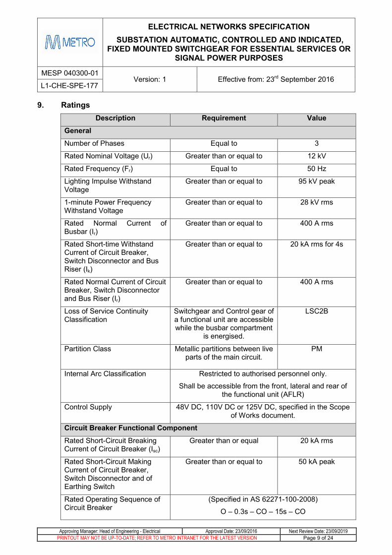
Ratings 9.Description Requirement Value
General Number of Phases Equal to 3
Rated Nominal Voltage (Ur) Greater than or equal to 12 kV
Rated Frequency (Fr) Equal to 50 Hz
Lighting Impulse Withstand Voltage
Greater than or equal to 95 kV peak
1-minute Power Frequency Withstand Voltage
Greater than or equal to 28 kV rms
Rated Normal Current of Busbar (Ir)
Greater than or equal to 400 A rms
Rated Short-time Withstand Current of Circuit Breaker, Switch Disconnector and Bus Riser (Ik)
Greater than or equal to 20 kA rms for 4s
Rated Normal Current of Circuit Breaker, Switch Disconnector and Bus Riser (Ir)
Greater than or equal to 400 A rms
Loss of Service Continuity Classification
Switchgear and Control gear of a functional unit are accessible while the busbar compartment
is energised.
LSC2B
Partition Class Metallic partitions between live parts of the main circuit.
PM
Internal Arc Classification Restricted to authorised personnel only.
Shall be accessible from the front, lateral and rear of the functional unit (AFLR)
Control Supply 48V DC, 110V DC or 125V DC, specified in the Scope of Works document.
Circuit Breaker Functional Component
Rated Short-Circuit Breaking Current of Circuit Breaker (Isc)
Greater than or equal 20 kA rms
Rated Short-Circuit Making Current of Circuit Breaker, Switch Disconnector and of Earthing Switch
Greater than or equal to 50 kA peak
Rated Operating Sequence of Circuit Breaker
(Specified in AS 62271-100-2008)
O – 0.3s – CO – 15s – CO
ELECTRICAL NETWORKS SPECIFICATION SUBSTATION AUTOMATIC, CONTROLLED AND INDICATED,
FIXED MOUNTED SWITCHGEAR FOR ESSENTIAL SERVICES OR SIGNAL POWER PURPOSES
MESP 040300-01 Version: 1 Effective from: 23rd September 2016
L1-CHE-SPE-177
Approving Manager: Head of Engineering - Electrical Approval Date: 23/09/2016 Next Review Date: 23/09/2019 PRINTOUT MAY NOT BE UP-TO-DATE; REFER TO METRO INTRANET FOR THE LATEST VERSION Page 10 of 24
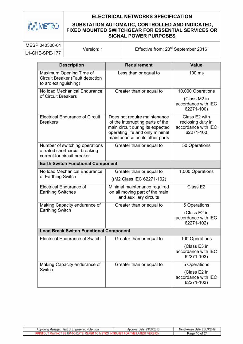
Description Requirement Value
Maximum Opening Time of Circuit Breaker (Fault detection to arc extinguishing)
Less than or equal to 100 ms
No load Mechanical Endurance of Circuit Breakers
Greater than or equal to
10,000 Operations
(Class M2 in accordance with IEC
62271-100)
Electrical Endurance of Circuit Breakers
Does not require maintenance of the interrupting parts of the
main circuit during its expected operating life and only minimal maintenance on its other parts
Class E2 with reclosing duty in
accordance with IEC 62271-100
Number of switching operations at rated short-circuit breaking current for circuit breaker
Greater than or equal to
50 Operations
Earth Switch Functional Component No load Mechanical Endurance of Earthing Switch
Greater than or equal to
((M2 Class IEC 62271-102)
1,000 Operations
Electrical Endurance of Earthing Switches
Minimal maintenance required on all moving part of the main
and auxiliary circuits
Class E2
Making Capacity endurance of Earthing Switch
Greater than or equal to 5 Operations
(Class E2 in accordance with IEC
62271-102)
Load Break Switch Functional Component
Electrical Endurance of Switch
Greater than or equal to 100 Operations
(Class E3 in accordance with IEC
62271-103)
Making Capacity endurance of Switch
Greater than or equal to 5 Operations
(Class E2 in accordance with IEC
62271-103)
ELECTRICAL NETWORKS SPECIFICATION SUBSTATION AUTOMATIC, CONTROLLED AND INDICATED,
FIXED MOUNTED SWITCHGEAR FOR ESSENTIAL SERVICES OR SIGNAL POWER PURPOSES
MESP 040300-01 Version: 1 Effective from: 23rd September 2016
L1-CHE-SPE-177
Approving Manager: Head of Engineering - Electrical Approval Date: 23/09/2016 Next Review Date: 23/09/2019 PRINTOUT MAY NOT BE UP-TO-DATE; REFER TO METRO INTRANET FOR THE LATEST VERSION Page 11 of 24
Functional Components Requirements 10.The specific requirements of each of the functional components are detailed in the following sections.
Circuit Breaker Functional Component 10.1The circuit breaker shall be a fixed mounted three pole vacuum interrupter with ratings specified in Section 9.
The circuit breaker shall be able to be operated electrically and manually.
The electrical closing and opening of the circuit breaker shall be able to be performed locally from the front of the functional unit and remotely from the SCADA system.
The manual closing and opening of the circuit breaker shall be performed with an operating lever provided with the circuit breaker.
A mechanical indication of the status of the circuit breaker shall be provided on the front of the functional unit. (Indicating lights are detailed in Section 10.8.1)
The circuit breaker shall be fitted with a non-resettable mechanical operations counter.
There shall be a minimum of 3 normally open and 3 normally closed voltage free auxiliary contacts provided for control and indication purposes in addition to those required for operation and local indication of the circuit breaker.
A pushbutton shall be provided on the circuit breaker to open the circuit breaker locally as may be required under emergency conditions.
Load Break Switch Functional Component 10.2The load break switch shall be a three pole vacuum switch.
The load break switch shall be a fixed mounted type and shall be manually operated from the front of the cubicle with its compartment closed.
A mechanical indication of the status of the load break switch shall be provided on the front of the functional unit.
The load break switch shall be fitted with a non-resettable mechanical operations counter.
There shall be a minimum of 1 normally open and 1 normally closed voltage free auxiliary contacts provided for control and indication purposes.
Earth Switch / Disconnector Functional Component 10.3This functional component may be provided either as one two position device (connected and earthed), or as one three position device (connected, disconnected and earthed), or as two separate two position devices – a disconnector and an earth switch (if associated with a load break switch, this may take the place of the disconnector). It provides the capability to earth the line side of the functional unit.
The earth switch shall be a manually operated, fault making switch. An anti-reflex lever operated mechanism which is independent of the operator action shall be provided to manually open or close the earth switch.
ELECTRICAL NETWORKS SPECIFICATION SUBSTATION AUTOMATIC, CONTROLLED AND INDICATED,
FIXED MOUNTED SWITCHGEAR FOR ESSENTIAL SERVICES OR SIGNAL POWER PURPOSES
MESP 040300-01 Version: 1 Effective from: 23rd September 2016
L1-CHE-SPE-177
Approving Manager: Head of Engineering - Electrical Approval Date: 23/09/2016 Next Review Date: 23/09/2019 PRINTOUT MAY NOT BE UP-TO-DATE; REFER TO METRO INTRANET FOR THE LATEST VERSION Page 12 of 24
The earth switch shall be provided with a descriptive indication on the front panel. The contacts of the earth switch shall be clearly visible from the front of the panel.
A built-in padlocking facility with a minimum 6mm shank shall be provided to enable the earth switch to be secured in the closed position. If internal illumination is required for the contacts to be visible, it shall be provided by a double insulated non-metallic light fitted to the circuit breaker, powered by the control supply. The Light shall be able to be replaced from outside the cubicle without requiring de-energisation. The Light shall be switched by means of a spring-return, push-button switch, ensuring the earth switch is only illuminated whilst the push-button switch is being depressed.
Busbar Functional Component 10.4A single busbar system shall be provided. It shall be modular in design to connect all the functional units together.
The busbar shall be encased with shielded solid insulation, be designed to be essentially maintenance free, not be able to be accessed and not be exposed to free air. For this reason no provision to earth the busbar is required.
Bus Indication Unit Functional Component 10.5The Bus Indication Unit is provided to monitor the status of the Busbar (Bus Alive), and the status of the normally unearthed System Voltage above Earth (Phase Earthed).
The bus indication unit shall be located on the front panel of the incoming supply circuit breaker and shall be positioned away from the incoming supply circuit breaker indication lights on each bus as per Table 1.
The detection of the Bus Alive and Phase Earth status can be achieved by either voltage transformer or capacitive coupling devices.
The unit shall provide the following outputs:
• Bus Alive Local Indicating Light (Red)
• Bus Alive SCADA Indication
• Red Phase Earthed local indicating light (Orange)
• White Phase Earthed local indicating light (Orange)
• Blue Phase Earthed local indicating light (Orange)
• Red Phase Earthed SCADA Indication
• White Phase Earthed SCADA Indication
• Blue Phase Earthed SCADA Indication
The Phase Earthed SCADA Indications shall be suppressed when the bus is de-energised. This shall include any transient false indications on energisation and de-energisation.
ELECTRICAL NETWORKS SPECIFICATION SUBSTATION AUTOMATIC, CONTROLLED AND INDICATED,
FIXED MOUNTED SWITCHGEAR FOR ESSENTIAL SERVICES OR SIGNAL POWER PURPOSES
MESP 040300-01 Version: 1 Effective from: 23rd September 2016
L1-CHE-SPE-177
Approving Manager: Head of Engineering - Electrical Approval Date: 23/09/2016 Next Review Date: 23/09/2019 PRINTOUT MAY NOT BE UP-TO-DATE; REFER TO METRO INTRANET FOR THE LATEST VERSION Page 13 of 24
a) Voltage Transformers If voltage transformers are used, two Voltage Transformers shall be provided.
The Voltage Transformers shall comply with AS 60044.2: Instrument transformers - Inductive voltage transformers. It shall be rated at 50 VA, 110 V, Class M.
A means of isolating the Voltage Transformers from the Busbar shall be provided for fault finding and testing purposes.
b) Capacitive Coupling Devices The capacitive coupling device and associated presence indicating system shall meet the requirements of IEC 62271-206. The device shall provide a reliable indication of the system voltage.
Power Cable Termination Functional Component 10.6The power cable terminals shall be in a separate metal enclosed compartment with a minimum depth of 500mm.
The compartment shall be suitable for the power cables to enter from above and below the functional unit.
The power cable terminals shall be suitable for the connection of a terminated and insulated cable. The cross-section area of the cable cores shall be between 16 and 35mm².
Appropriate brackets and clamps shall be provided to adequately support the cables in the compartment so that the weight of the conductor is not taken by the terminals.
Appropriate brackets shall be provided to securely position and fix a current transformer or cable fault detector if required, within the cable termination compartment.
The middle termination shall be provided with a shielded insulated cover.
A ‘DANGER HIGH VOLTAGE’ sign shall be placed on the Power Cable Termination door.
a) Current Transformers Current Transformers shall be mounted within each cable termination compartment. Unless the Scope of Works Document requires otherwise, the CTs shall be rated at 50:1, 1VA, 5P20 in accordance with AS 60044.1: Instrument transformers – Current transformers.
b) Voltage Transformers Voltage Transformers shall be able to be fitted in the cable termination compartment of Feeder Circuit Breaker Units. The Scope of Works Document will describe which compartments require VTs to be installed and the secondary voltage of those VTs.
The Voltage Transformers shall comply with AS 60044.2: Instrument transformers - Inductive voltage transformers. It shall be rated at 3300V or 2200V/230V, 30 VA, Class M. VR-VAU1
A means of isolating the Voltage Transformers shall be provided for fault finding and testing purposes.
The cable termination compartment shall be sized to ensure adequate clearances are maintained with VTs installed.

ELECTRICAL NETWORKS SPECIFICATION SUBSTATION AUTOMATIC, CONTROLLED AND INDICATED,
FIXED MOUNTED SWITCHGEAR FOR ESSENTIAL SERVICES OR SIGNAL POWER PURPOSES
MESP 040300-01 Version: 1 Effective from: 23rd September 2016
L1-CHE-SPE-177
Approving Manager: Head of Engineering - Electrical Approval Date: 23/09/2016 Next Review Date: 23/09/2019 PRINTOUT MAY NOT BE UP-TO-DATE; REFER TO METRO INTRANET FOR THE LATEST VERSION Page 14 of 24
Phase Test and Line Alive Functional Component 10.7Provision shall be provided for testing the power cable for phase identification without dismantling the power cable connections.
Provision shall be provided for a testing device to be connected at the front of the functional unit.
The block shall also include an LED indication to indicate if each of the phases is alive.
The phase test and line alive functional block shall be provided to monitor the line or bus side of the functional unit as detailed in Table 1.
The line alive LED indication shall be appropriately labelled and positioned in line with a single line mimic to assist the operator to view the device being monitored.
A SCADA indication shall be provided to indicate a line alive status.
The functional block shall meet the requirements of standard IEC 62271-206.
Control and Protection Functional Component 10.8
Control Requirements 10.8.1Each functional unit as specified in Table 1 shall be provided with a metallically segregated Low Voltage Control Compartment. It shall be located at the front of the Cubicle.
The compartment shall contain all of the measurement, control, protection and auxiliary equipment necessary for the operation of the functional units.
Access to the compartment shall be by a hinged, dustproof door with a non-locking handle.
The Circuit Breaker Functional unit shall be locally controlled by a control switch on the front panel of the circuit breaker fitted with a pistol grip handle. The control switch shall be positioned at an accessible height no greater than 1.6 meters from ground level. It shall have a neutral centre position, with closure of the circuit breaker when the control switch is turned to the left of centre and opening of the circuit breaker when the switch is turned to the right of centre. The control switch shall have a spring return to the centre position. The switch shall be labelled “Trip”, “Normal” and “Close” for the relative position.
Indicating Lights shall be provided on the front panel of the circuit breaker for the Open (Green) and Closed (Red) indications of the Circuit Breaker. These shall be energized by dedicated and electrically isolated auxiliary contacts of the Circuit Breaker.
All Indicating Lights shall be long life; high reliability type LED lights.
The control circuit shall contain interposing relays for remote SCADA control operations. The interposing “Open” relay coil and “Close” relay coil shall have a current consumption of 60 - 100 mA at the Control Voltage. The operate pulse time of the SCADA system is 1 second. Device labels ‘#216’ for Open and “#217’ for Close shall be provided.
ELECTRICAL NETWORKS SPECIFICATION SUBSTATION AUTOMATIC, CONTROLLED AND INDICATED,
FIXED MOUNTED SWITCHGEAR FOR ESSENTIAL SERVICES OR SIGNAL POWER PURPOSES
MESP 040300-01 Version: 1 Effective from: 23rd September 2016
L1-CHE-SPE-177
Approving Manager: Head of Engineering - Electrical Approval Date: 23/09/2016 Next Review Date: 23/09/2019 PRINTOUT MAY NOT BE UP-TO-DATE; REFER TO METRO INTRANET FOR THE LATEST VERSION Page 15 of 24
A two position C&I Isolating Switch, with pistol grip handle and a yellow escutcheon shall be provided to isolate the control and indication function of the circuit breaker from the SCADA System. When in the isolate position, both control and indication shall be isolated from remote operation by breaking the common connection. The Switch positions shall be labelled “Isolated” and “Normal”.
A single switch shall be provided to switch on and off the Indicating Lights on the switchgear assembly. A push button type ‘Test Switch’ for the testing of all lights shall be provided.
The opening of the circuit breaker under a fault condition, remotely, or via a pushbutton on the panel shall not require the need for another open command to reclose the circuit breaker.
The control of the circuit breaker shall be achieved as simply as possible via relay logic, and preferably without the use of programmable logic controllers.
For a two bus switchboard configuration, a separate control supply shall be provided for each bus.
The layout of switches, lights and buttons on the control panel shall be approved by MTM prior to commencement of manufacture.
Protection System Requirements 10.8.2The Functional Unit shall be provided with an overcurrent protection system utilising a Micom P120 type relay. All relays shall be programmed for Distributed Network Protocol (DNP3) communication.
The Protection Relay shall be securely mounted on the low voltage control compartment door and positioned no greater than 1.6 meters from ground level.
10.9 The Protection Relay shall be provided with isolating Test Links mounted on the door. The preferred Test Terminals are Weidmuller type WTL6/1/STB – part no. 1016900000 or equivalent. The Test Links shall be connected to each of the Current Transformer connections to the Relay, and to the main Tripping Contacts of the relay.Bus Riser Functional Component
A bus riser functional component will be required to interconnect a two bus switchboard configuration and shall be designed for easy integration to other functional units. The bus riser unit shall ensure the integrity of the shielded solid insulation encasing the bus bar is maintained.
Interlocking Requirements 11.
Functional Unit Interlocking Requirements 11.1The circuit breaker functional unit and the load break switch functional unit shall have identical interlocking requirements. For the purpose of this section, the circuit breaker and the load break switch have been referred to as the main switch of the functional unit.
The earth switch shall be mechanically interlocked with its main switch. This is to prevent operation of the earth switch while the main switch of the functional unit is closed, and to prevent the closing of the main switch while the earth switch is closed. This shall apply to the electrical and manual operation of the main switch and earth switch.

ELECTRICAL NETWORKS SPECIFICATION SUBSTATION AUTOMATIC, CONTROLLED AND INDICATED,
FIXED MOUNTED SWITCHGEAR FOR ESSENTIAL SERVICES OR SIGNAL POWER PURPOSES
MESP 040300-01 Version: 1 Effective from: 23rd September 2016
L1-CHE-SPE-177
Approving Manager: Head of Engineering - Electrical Approval Date: 23/09/2016 Next Review Date: 23/09/2019 PRINTOUT MAY NOT BE UP-TO-DATE; REFER TO METRO INTRANET FOR THE LATEST VERSION Page 16 of 24
The earth switch shall be interlocked with the line alive indication such that the earth switch cannot be closed unless the line side is de-energised.
The compartment housing the power cable terminals shall have interlock-controlled access. It shall only be accessible when the line earth switch is closed.
The main switch shall be prevented from closing if the cable termination door is open.
Wiring 12.The control and auxiliary wiring terminals for connection to external circuits shall be located in a suitable position inside the control compartment.
The terminals for the external SCADA cables shall be disconnect test terminals with test sockets. This is to facilitate the isolation of the SCADA cables for testing and fault finding purposes of the input and output Essential Services. All terminals shall be screw type terminals, such that set screws shall be used to secure wiring in terminals.
All conductors used for control voltage wiring shall be stranded copper and have a cross sectional area of not less than 1.5 mm² and shall be insulated to 2 kV.
A system of permanent labelling for identification of all cables shall be used. The label shall appear on each end of each wire. The label shall be securely attached to the cables and be easily readable.
All wiring shall be arranged as simple as possible so that the course of each conductor may be readily traced.
All SCADA related terminals shall be positioned together.
A terminal layout drawing shall be provided by the manufacturer.
Accessories 13.
Marking and Labelling 13.1All switching devices, control switches, components and indicators shall be labelled and have appropriate warning signs.
The external labels on each functional unit shall be of the Traffolyte type and shall be fastened by screws or equivalent.
The switchboard shall feature a mimic diagram showing the connection of each switching device and any voltage transformers.
All control wiring shall have sleeved cable markers.
Anti-condensation Heaters 13.2An anti-condensation heater shall be fitted in each functional unit.
The heaters shall be powered from the 230V AC supply of the Substation which may be either phase to phase, or phase to neutral. A two pole switch shall be provided in each Control Compartment to switch off the heater(s).

ELECTRICAL NETWORKS SPECIFICATION SUBSTATION AUTOMATIC, CONTROLLED AND INDICATED,
FIXED MOUNTED SWITCHGEAR FOR ESSENTIAL SERVICES OR SIGNAL POWER PURPOSES
MESP 040300-01 Version: 1 Effective from: 23rd September 2016
L1-CHE-SPE-177
Approving Manager: Head of Engineering - Electrical Approval Date: 23/09/2016 Next Review Date: 23/09/2019 PRINTOUT MAY NOT BE UP-TO-DATE; REFER TO METRO INTRANET FOR THE LATEST VERSION Page 17 of 24
Prohibited Materials 13.3There shall be no asbestos or materials containing asbestos in the Switchgear and Control gear. A statement certifying that the product is free of asbestos containing materials must be completed and signed, and delivered to MTM prior to dispatch.
Arc Venting 14.The tenderer shall indicate if arc venting is required with the equipment offered, to meet the conditions of the equipment type tests, under the voltage and current fault levels specified.
Testing 15.
Type Test 15.1The Switchgear shall have Type Test Certificates complying with AS 62271. The Certificates shall include oscillograms and drawings of the test circuit. Copies of these Certificates shall be supplied with the tender documentation.
Routine Tests 15.2The Switchgear and Control gear shall be subjected to Routine Tests at the Manufacturer’s Workshop complying with AS 62271.
MTM reserves the right to appoint a representative to witness these Tests. Seven working days’ notification shall be given to MTM of intention to carry out factory testing. The results of all Routine Tests shall be recorded on test certificates. The test certificates shall clearly show the performance of the equipment and shall be accompanied by tables showing the actually measured values and all calculations.
The test certificates shall be forwarded to MTM and the results approved by MTM prior to delivery.
The specific requirements of an inspection and test plan for each site will be specified in the scope of works.
Spares 16.The Supplier shall provide a list of spares which it considers necessary to ensure prompt repair of the equipment, including relays, switches and other items.
Documentation and Support 17.The Supplier must supply all materials, special tools and documents for the Switchgear and Control gear. The documents shall contain all necessary information and instructions required for operation and maintenance of all items.

ELECTRICAL NETWORKS SPECIFICATION SUBSTATION AUTOMATIC, CONTROLLED AND INDICATED,
FIXED MOUNTED SWITCHGEAR FOR ESSENTIAL SERVICES OR SIGNAL POWER PURPOSES
MESP 040300-01 Version: 1 Effective from: 23rd September 2016
L1-CHE-SPE-177
Approving Manager: Head of Engineering - Electrical Approval Date: 23/09/2016 Next Review Date: 23/09/2019 PRINTOUT MAY NOT BE UP-TO-DATE; REFER TO METRO INTRANET FOR THE LATEST VERSION Page 18 of 24
Documentation Requirements 17.1All documentation shall be provided in English.
One electronic and eight paper copies of the each final document shall be provided and the content shall be identical in each copy.
Every page of the documentation shall be clearly identified in relation to the document to which it belongs and the version of that document. All pages of multi-page documents shall be uniquely numbered. It shall be possible to readily determine if all pages of a document are present.
Manuals shall be A4 size and shall be bound in durable covers or in 4-D ring binders.
Drawing Format 17.2All drawings must comply with the PTV Infrastructure Drafting Standard
Files shall be provided in Microstation format and PDF on a compact disk (CD).
Technical Maintenance Plan 17.3A Technical Maintenance Plan which establishes the maintenance policy for the Switchgear as recommended by the Supplier shall be provided. This shall detail the preventative servicing schedules and maintenance intervals for all components. The servicing schedules shall reference appropriate detailed instructions in the maintenance manual.
A condition based maintenance interval shall be provided to optimise the balance between maintenance work and risk of failure.
The Technical Maintenance Plan shall contain a list of any recommended spare parts, detailing price, supplier and procurement lead-times.
The Technical Maintenance Plan shall detail safe disposal procedures applicable for when the Assembly is no longer serviceable (recycling, hazardous waste etc.).
Maintenance Manual 17.4The Maintenance Manual shall detail:
a) The theory of operation of the equipment.
b) All servicing activities.
c) Overhaul instructions.
d) Adjustment procedures.
e) The changing of components for repairs.
f) Fault-finding procedures.
g) The spares support schedule.
The Maintenance Manual shall also include a complete set of as-built drawings and a comprehensive parts list for the Assembly.
ELECTRICAL NETWORKS SPECIFICATION SUBSTATION AUTOMATIC, CONTROLLED AND INDICATED,
FIXED MOUNTED SWITCHGEAR FOR ESSENTIAL SERVICES OR SIGNAL POWER PURPOSES
MESP 040300-01 Version: 1 Effective from: 23rd September 2016
L1-CHE-SPE-177
Approving Manager: Head of Engineering - Electrical Approval Date: 23/09/2016 Next Review Date: 23/09/2019 PRINTOUT MAY NOT BE UP-TO-DATE; REFER TO METRO INTRANET FOR THE LATEST VERSION Page 19 of 24
Installation Instructions Manual 17.5The installation Instructions Manual shall enable the Switchgear to be properly installed, tested and commissioned. This shall include all necessary drawings, and information regarding the storage, handling, loading and off-loading instructions.
Operating Instructions Manual 17.6The Operating Instructions Manual shall clearly describe the required procedures for physically operating all of the components of the Switchgear.
The operating procedures shall be consistent with the PTC Train Infrastructure Electrical Safety Rules (High Voltage Rules) (IPGOR-01) and the Victorian Traction Industry Electrical Safety Rules 2014 (Orange Book).
Training 17.7The manufacturer shall provide full training for a person nominated by MTM. The training shall include instruction on the operation and maintenance of the switchgear, to a sufficient level to in turn instruct MTM staff and its agents.
The manufacturer shall prepare a suitable operating instruction for the switchgear, in the required MTM format, for the objective of training of MTM staff and its agents.
Tools & Equipment 17.8A complete set of operating tools and any other equipment necessary to operate and maintain the Switchgear and Control gear shall be provided with each assembly. This shall include any special devices required to test the Switchgear and Control gear. Storage facilities for the tools and equipment shall also be provided.
The software and a portable computer interface for loading and downloading of Protection Relay settings and the latest fault current data to a laptop portable computer shall be provided. This shall include all peripheral interfacing equipment and connection cables necessary to connect and communicate with the system.
Any special lifting and installation equipment shall be supplied with the Switchgear.
Design Management Requirements 18.This section describes the documentation which should be provided as a minimum at each stage of the procurement process. The documentation shall comply with the specifications above.
ELECTRICAL NETWORKS SPECIFICATION SUBSTATION AUTOMATIC, CONTROLLED AND INDICATED,
FIXED MOUNTED SWITCHGEAR FOR ESSENTIAL SERVICES OR SIGNAL POWER PURPOSES
MESP 040300-01 Version: 1 Effective from: 23rd September 2016
L1-CHE-SPE-177
Approving Manager: Head of Engineering - Electrical Approval Date: 23/09/2016 Next Review Date: 23/09/2019 PRINTOUT MAY NOT BE UP-TO-DATE; REFER TO METRO INTRANET FOR THE LATEST VERSION Page 20 of 24
Tender Submission 18.1
The following documents shall be provided as part of the tender submission:
• Pamphlets detailing the operating and interlocking principles of the Switchgear and Control gear.
• A General Arrangement drawing of the Switchgear which clearly shows:
o The overall dimensions of the Switchgear and each Module.
o Details of the proposed cable terminals and cable entry requirements
o Typical Control Schematics
• Type Test Certificates
• The Technical Data Schedule in Section 19 filled in.
• A list of recommended spare parts.
Contract Documentation 18.2One set of PDF copies of the drawings and documentation detailed in Section 17, including any other information considered necessary for completeness shall be provided for review and approval by MTM four weeks after the Contact Award Date. No manufacture shall commence until the drawings have been approved. An allowance of seven working days should be made by the Supplier for the review and approval of submitted documents.
A draft Installation Instructions Manual shall also be included.
Pre-Delivery Documentation 18.3Prior to delivery, the Supplier shall provide the paper and electronic copies of the Manuals, Drawings and Routine Test Certificates.
ELECTRICAL NETWORKS SPECIFICATION SUBSTATION AUTOMATIC, CONTROLLED AND INDICATED,
FIXED MOUNTED SWITCHGEAR FOR ESSENTIAL SERVICES OR SIGNAL POWER PURPOSES
MESP 040300-01 Version: 1 Effective from: 23rd September 2016
L1-CHE-SPE-177
Approving Manager: Head of Engineering - Electrical Approval Date: 23/09/2016 Next Review Date: 23/09/2019 PRINTOUT MAY NOT BE UP-TO-DATE; REFER TO METRO INTRANET FOR THE LATEST VERSION Page 21 of 24
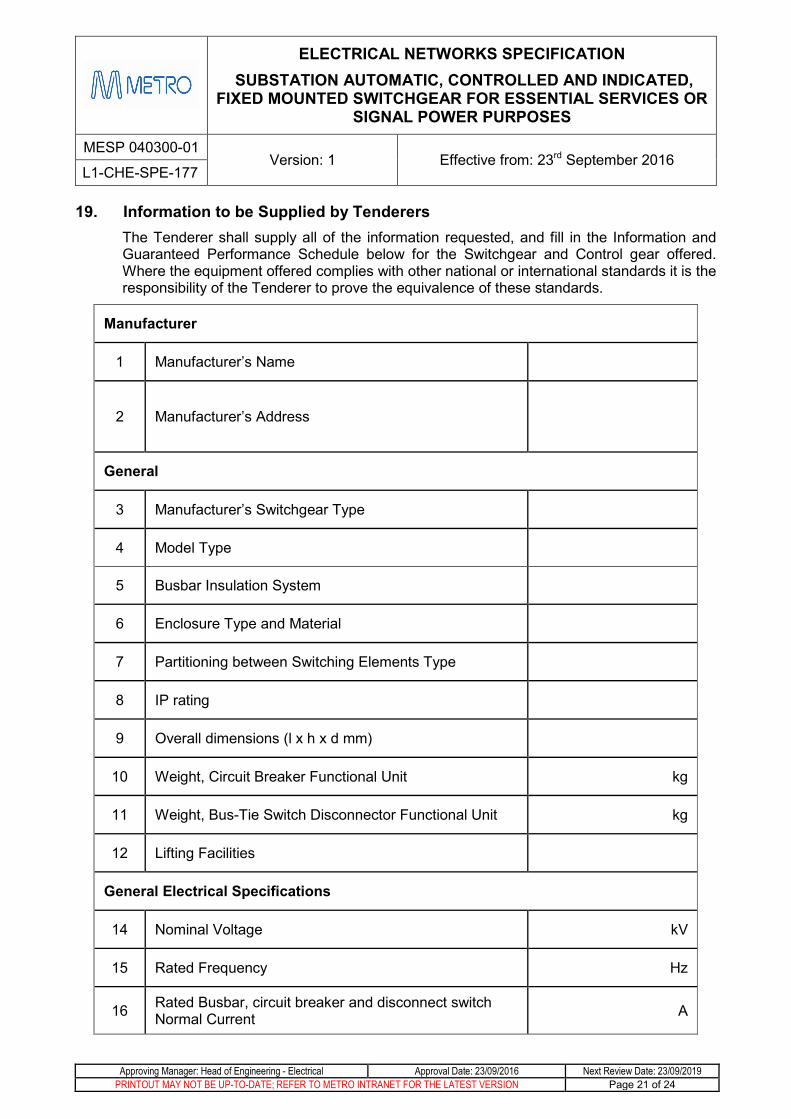
Information to be Supplied by Tenderers 19.The Tenderer shall supply all of the information requested, and fill in the Information and Guaranteed Performance Schedule below for the Switchgear and Control gear offered. Where the equipment offered complies with other national or international standards it is the responsibility of the Tenderer to prove the equivalence of these standards.
Manufacturer
1 Manufacturer’s Name
2 Manufacturer’s Address
General
3 Manufacturer’s Switchgear Type
4 Model Type
5 Busbar Insulation System
6 Enclosure Type and Material
7 Partitioning between Switching Elements Type
8 IP rating
9 Overall dimensions (l x h x d mm)
10 Weight, Circuit Breaker Functional Unit kg
11 Weight, Bus-Tie Switch Disconnector Functional Unit kg
12 Lifting Facilities
General Electrical Specifications
14 Nominal Voltage kV
15 Rated Frequency Hz
16 Rated Busbar, circuit breaker and disconnect switch Normal Current A
ELECTRICAL NETWORKS SPECIFICATION SUBSTATION AUTOMATIC, CONTROLLED AND INDICATED,
FIXED MOUNTED SWITCHGEAR FOR ESSENTIAL SERVICES OR SIGNAL POWER PURPOSES
MESP 040300-01 Version: 1 Effective from: 23rd September 2016
L1-CHE-SPE-177
Approving Manager: Head of Engineering - Electrical Approval Date: 23/09/2016 Next Review Date: 23/09/2019 PRINTOUT MAY NOT BE UP-TO-DATE; REFER TO METRO INTRANET FOR THE LATEST VERSION Page 22 of 24
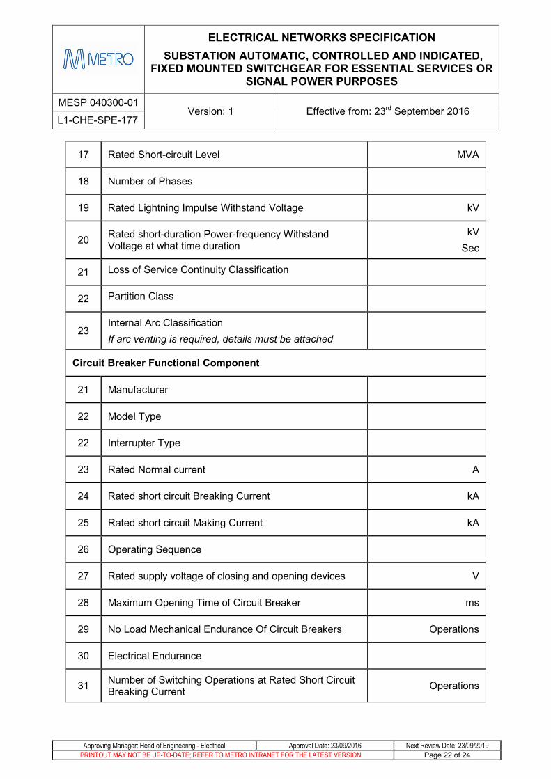
17 Rated Short-circuit Level MVA
18 Number of Phases
19 Rated Lightning Impulse Withstand Voltage kV
20 Rated short-duration Power-frequency Withstand Voltage at what time duration
kV Sec
21 Loss of Service Continuity Classification
22 Partition Class
23 Internal Arc Classification If arc venting is required, details must be attached
Circuit Breaker Functional Component
21 Manufacturer
22 Model Type
22 Interrupter Type
23 Rated Normal current A
24 Rated short circuit Breaking Current kA
25 Rated short circuit Making Current kA
26 Operating Sequence
27 Rated supply voltage of closing and opening devices V
28 Maximum Opening Time of Circuit Breaker ms
29 No Load Mechanical Endurance Of Circuit Breakers Operations
30 Electrical Endurance
31 Number of Switching Operations at Rated Short Circuit Breaking Current Operations

ELECTRICAL NETWORKS SPECIFICATION SUBSTATION AUTOMATIC, CONTROLLED AND INDICATED,
FIXED MOUNTED SWITCHGEAR FOR ESSENTIAL SERVICES OR SIGNAL POWER PURPOSES
MESP 040300-01 Version: 1 Effective from: 23rd September 2016
L1-CHE-SPE-177
Approving Manager: Head of Engineering - Electrical Approval Date: 23/09/2016 Next Review Date: 23/09/2019 PRINTOUT MAY NOT BE UP-TO-DATE; REFER TO METRO INTRANET FOR THE LATEST VERSION Page 23 of 24
Load Break Switch Functional Component
35 Type
36 Model Type
37 Rated Normal current A
38 Rated Breaking Current A
39 Rated Making Current A
40 Interlocking Mechanism with Circuit Breaker
41 Interlocking Mechanism with Line Status
42 Electrical Endurance of Switch
43 Making Capacity endurance of Main Switch
Earth Switch Functional Component
44 Configuration (single two-position, single three-position, two two-position devices)
45 Model Type
46 Rated Normal current A
47 Rated Short circuit Making Current A
48 Interlocking Mechanism with Line Disconnector
49 Interlocking Mechanism with Line Status
50 Is Switch able to be viewed in both Open and Closed positions? Yes / No
51 Electrical Endurance of Earthing Switches
52 No load Mechanical Endurance of Earthing Switch
53 Making Capacity endurance of Earthing Switch

ELECTRICAL NETWORKS SPECIFICATION SUBSTATION AUTOMATIC, CONTROLLED AND INDICATED,
FIXED MOUNTED SWITCHGEAR FOR ESSENTIAL SERVICES OR SIGNAL POWER PURPOSES
MESP 040300-01 Version: 1 Effective from: 23rd September 2016
L1-CHE-SPE-177
Approving Manager: Head of Engineering - Electrical Approval Date: 23/09/2016 Next Review Date: 23/09/2019 PRINTOUT MAY NOT BE UP-TO-DATE; REFER TO METRO INTRANET FOR THE LATEST VERSION Page 24 of 24
Bus Tie Circuit Breaker Functional Block
54 Rated Normal current A
55 Rated Short Circuit Making Current kA
56 Interlocking System with Circuit Breakers and Disconnectors
57 Is Switch able to be viewed in both Open and Closed positions? Yes / No
Bus Riser Functional Block
58 Rated Normal current A
59 Rated Short Circuit Making Current kA
60 Interlocking System with Circuit Breakers and Disconnectors
61 Is Switch able to be viewed in both Open and Closed positions? Yes / No
Indication and Protection Systems Functional Block
62 Line Protection Relay Manufacturer
63 Relay Model
64 Current Transformer Manufacturer & Type
65 Current Transformer Ratios
66 Voltage Transformer Manufacture & Type
67 Voltage Transformer Ratings
Cable Termination Compartment Functional Block
68 Voltage Transformer Manufacture & Type
69 Voltage Transformer Ratings
70 Compartment dimensions