MESP 010900-03 TECHNICAL SPECIFICATION FOR 22 … · MESP 010900-03 TECHNICAL SPECIFICATION FOR ......
24
PRINTOUT MAY NOT BE UP-TO-DATE; REFER TO METRO INTRANET FOR THE LATEST VERSION Engineering Specification Electrical Networks MESP 010900-03 TECHNICAL SPECIFICATION FOR 22 kV METAL ENCLOSED SWITCHGEAR Version: 2 Issued: 19 th December 2016 Owner: Chief Engineer Approved By: Andrew Russack Head of Engineering - Electrical
-
Upload
duongxuyen -
Category
Documents
-
view
235 -
download
0
Transcript of MESP 010900-03 TECHNICAL SPECIFICATION FOR 22 … · MESP 010900-03 TECHNICAL SPECIFICATION FOR ......

PRINTOUT MAY NOT BE UP-TO-DATE; REFER TO METRO INTRANET FOR THE LATEST VERSION
Engineering Specification
Electrical Networks
MESP 010900-03
TECHNICAL SPECIFICATION FOR
22 kV METAL ENCLOSED SWITCHGEAR
Version: 2
Issued: 19th December 2016
Owner: Chief Engineer
Approved By:
Andrew Russack
Head of Engineering - Electrical

ELECTRICAL NETWORKS SPECIFICATION TECHNICAL SPECIFICATION FOR 22 kV
METAL ENCLOSED SWITCHGEAR
MESP 010900-03 Version: 2 Effective from: 19th December 2016
L1-CHE-SPE-010
Approving Manager: Head of Engineering - Electrical Approval Date: 19/12/2016 Next Review Date: 19/12/2019 PRINTOUT MAY NOT BE UP-TO-DATE; REFER TO METRO INTRANET FOR THE LATEST VERSION Page 2 of 24
Approval
Amendment Record
Approval Date Version Description
17/12/2014 1 Initial issue under MTM.
19/12/2016 2 Additional VT requirements. Appendix B – Minor additions.

ELECTRICAL NETWORKS SPECIFICATION TECHNICAL SPECIFICATION FOR 22 kV
METAL ENCLOSED SWITCHGEAR
MESP 010900-03 Version: 2 Effective from: 19th December 2016
L1-CHE-SPE-010
Approving Manager: Head of Engineering - Electrical Approval Date: 19/12/2016 Next Review Date: 19/12/2019 PRINTOUT MAY NOT BE UP-TO-DATE; REFER TO METRO INTRANET FOR THE LATEST VERSION Page 3 of 24
Table of Contents
1. Purpose ................................................................................................................................................ 5
2. Scope ................................................................................................................................................... 5 3. Abbreviations ...................................................................................................................................... 5
4. Definitions ........................................................................................................................................... 5
5. References & Legislation ................................................................................................................... 5
6. Background ......................................................................................................................................... 6
7. Configuration ...................................................................................................................................... 7
8. Operating Conditions ......................................................................................................................... 7
8.1 Service Conditions ............................................................................................................ 7
8.2 Electrical Conditions ......................................................................................................... 7 9. Ratings ................................................................................................................................................. 7
10. General Requirements ....................................................................................................................... 8
10.1 Modules ............................................................................................................................ 8 10.2 Enclosure .......................................................................................................................... 8
10.3 Control Voltage ................................................................................................................. 9
10.4 Labelling ............................................................................................................................ 9
10.5 Anti-condensation Heaters ............................................................................................... 9
10.6 SCADA Interface............................................................................................................. 10
10.7 Prohibited Materials ........................................................................................................ 10 11. Busbar Requirements ...................................................................................................................... 10
11.1 Busbar Voltage Transformer and Bus Alive Indication ................................................... 10
11.2 Busbar Earthing Switch .................................................................................................. 11 12. Power Cable Termination Requirements ....................................................................................... 11
12.1 Terminal Requirements .................................................................................................. 11
12.2 Line Earth Switch Requirements .................................................................................... 11 12.3 Line Alive and Bus Alive Detection System Requirements ............................................ 12
13. Circuit Breaker Module Requirements ........................................................................................... 12
13.1 Circuit Breaker Requirements ......................................................................................... 12
13.2 Circuit Breaker Operation ............................................................................................... 13
13.3 Disconnector Requirements (Fixed Circuit Breaker only)............................................... 13
13.4 Circuit Breaker Test Position (Withdrawable Circuit Breaker only) ................................ 13 13.5 Power Terminal Compartment Additional Requirements ............................................... 13
13.6 Control Compartment Requirements .............................................................................. 14
13.7 Feeder Circuit Breaker Control System Requirements .................................................. 14
13.8 Rectifier Unit Circuit Breaker Control System Requirements ......................................... 15
13.9 Protection Scheme Requirements .................................................................................. 15
ELECTRICAL NETWORKS SPECIFICATION TECHNICAL SPECIFICATION FOR 22 kV
METAL ENCLOSED SWITCHGEAR
MESP 010900-03 Version: 2 Effective from: 19th December 2016
L1-CHE-SPE-010
Approving Manager: Head of Engineering - Electrical Approval Date: 19/12/2016 Next Review Date: 19/12/2019 PRINTOUT MAY NOT BE UP-TO-DATE; REFER TO METRO INTRANET FOR THE LATEST VERSION Page 4 of 24
13.10 Control Wiring Requirements .......................................................................................... 15 14. Testing ............................................................................................................................................... 16
14.1 Type Test ........................................................................................................................ 16
14.2 Routine Tests .................................................................................................................. 17 15. Documentation and Support ........................................................................................................... 17
15.1 Documentation Requirements ........................................................................................ 17
15.2 Design Drawings ............................................................................................................. 17
15.3 Drawing Format .............................................................................................................. 18
15.4 Technical Maintenance Plan ........................................................................................... 18
15.5 Maintenance Manual ...................................................................................................... 18 15.6 Installation Instructions Manual ...................................................................................... 18
15.7 Operating Instructions Manual ........................................................................................ 18
15.8 Tools & Equipment.......................................................................................................... 19 16. Information to be Supplied in Scope Document ........................................................................... 19
Appendix A – Design Management Requirements ............................................................................ 20
Appendix B – Information to be Supplied by Tenderers ..................................................................... 21

ELECTRICAL NETWORKS SPECIFICATION TECHNICAL SPECIFICATION FOR 22 kV
METAL ENCLOSED SWITCHGEAR
MESP 010900-03 Version: 2 Effective from: 19th December 2016
L1-CHE-SPE-010
Approving Manager: Head of Engineering - Electrical Approval Date: 19/12/2016 Next Review Date: 19/12/2019 PRINTOUT MAY NOT BE UP-TO-DATE; REFER TO METRO INTRANET FOR THE LATEST VERSION Page 5 of 24
1. Purpose This document is the MTM technical specification for Modular, Single and Multi Busbar, Metal Enclosed, Partitioned, 22kV Switchgear and Controlgear with fixed or withdrawable Switching Devices.
2. Scope This document applies to the supply of the Switchgear and Controlgear for use in a new Traction Substation, and for upgrades and renewals of existing Traction Substations, on the MTM Traction Power Supply System, where the installation requires only a single busbar.
3. Abbreviations MTM - Metro Trains Melbourne
SCADA - Supervisory Control and Data Acquisition
4. Definitions For all technical terms refer to AS 62271
Shall Is used as the descriptive word to express a requirement that is mandatory to achieve conformance to the standard.
Should Is used as the descriptive word to express a requirement that is recommended in order to achieve compliance to the standard. Should can also be used if a requirement is a design goal but not a mandatory requirement.
5. References & Legislation The Switchgear and Controlgear shall comply with the following Australian Standards and Acts.
Standard/Act Title
AS 2650 High Voltage A.C. Switchgear and Controlgear Common Requirements
AS 2791 High-Voltage Switchgear And Controlgear - Use And Handling Of Sulphur Hexafluoride (SF6) In High Voltage Switchgear And Controlgear
AS 60044.1 Instrument transformers - Current transformers
AS 60044.2 Instrument transformers- Inductive voltage transformers
AS/NZS 60137 Insulated bushings for alternating voltage above 1000V
IEC 60255 Measuring relays and protection equipment
IEC 60376 Specification of technical grade sulphur hexafluoride (SF6) for use in electrical equipment

ELECTRICAL NETWORKS SPECIFICATION TECHNICAL SPECIFICATION FOR 22 kV
METAL ENCLOSED SWITCHGEAR
MESP 010900-03 Version: 2 Effective from: 19th December 2016
L1-CHE-SPE-010
Approving Manager: Head of Engineering - Electrical Approval Date: 19/12/2016 Next Review Date: 19/12/2019 PRINTOUT MAY NOT BE UP-TO-DATE; REFER TO METRO INTRANET FOR THE LATEST VERSION Page 6 of 24
Standard/Act Title
IEC 60445 Basic and safety principles for man-machine interface, marking and identification – Identification of equipment terminals, conductor terminations and conductors
AS 60529-2004 Degrees of protection provided by enclosures (IP Code) AS 62271.1 High-voltage Switchgear and Controlgear - Common specifications
AS 62271.100 High-voltage Switchgear and Controlgear – High-voltage alternating-current circuit breakers
AS 62271.200 High-voltage Switchgear and Controlgear – AC Metal enclosed switchgear and controlgear for rated voltages above 1kV and up to 52kV
AS 62271.201 High-voltage Switchgear and Controlgear – AC Insulation-enclosed switchgear and controlgear for rated voltages above 1kV and up to 52kV
AS 62271.301 High-voltage Switchgear and Controlgear – Dimensional standardization of terminals
AS 62271.308 High-voltage Switchgear and Controlgear – Guide for asymmetrical short-circuit breaker test duty
Victorian
Rail Safety Act 2006 (Victoria)
Occupational Health and Safety Act 2004 (Victoria)
Occupational Health and Safety Regulation 2007 (Victoria)
Electricity Safety Act 1998 (Victoria)
Electricity Safety (Installations) Regulations 2009 (Victoria)
If the equipment offered does not comply with Australian Standards, but complies with similar International Standards (e.g. IEC), then detailed descriptions shall be given of the differences between the apparatus offered and the requirements of the specified Australian Standard.
6. Background The Melbourne Traction Substations primarily convert electricity from High Voltage AC to 1500 Volt DC power for the operation of the Electric Train System in Melbourne.
There are two types of 22 kV Switchgear and Controlgear specifications applicable to new MTM Substations. The choice is dependent on the Substation application.
The two Switchgear applications are:
1. A Single Busbar 22 kV Switchgear with fixed Circuit Breaker protected Supply Feeders and Rectifier Unit, and Fuse protected secondary Transformers.
ELECTRICAL NETWORKS SPECIFICATION TECHNICAL SPECIFICATION FOR 22 kV
METAL ENCLOSED SWITCHGEAR
MESP 010900-03 Version: 2 Effective from: 19th December 2016
L1-CHE-SPE-010
Approving Manager: Head of Engineering - Electrical Approval Date: 19/12/2016 Next Review Date: 19/12/2019 PRINTOUT MAY NOT BE UP-TO-DATE; REFER TO METRO INTRANET FOR THE LATEST VERSION Page 7 of 24
2. A multiple Busbar 22 kV Switchgear with withdrawable Circuit Breakers. This is for a Substation that requires greater operational flexibility and a more sophisticated protection system.
This is a common Specification for the 22kV Switchgear and Controlgear with fixed or withdrawable Circuit Breakers. It is intended that the Switchgear of this Specification be able to be installed indoors.
7. Configuration The Switchgear shall be modular with each module typically consisting of a Circuit Breaker and an earth switch. Modules with fixed type Circuit Breaker shall also have a line isolator.
A typical configuration could contain 4 or 5 Circuit Breaker modules on each bus.
Some locations require multiple bus arrangement with bus tie facility. The specific requirements for each Substation will be defined in a separate Scope Document.
8. Operating Conditions
8.1 Service Conditions The Switchgear will be installed indoors; on a solid concrete type or inside a portable building on steel framed floor.
The normal indoor service conditions as detailed in AS 62271.1 shall apply, with the exception that the maximum ambient air temperature shall be taken to be 45°C, and the air may be slightly polluted by dust.
8.2 Electrical Conditions The Switchgear will be connected to a 22kV, 50 Hz Distribution System. The System shall be considered as non-effectively earthed.
The design fault level of the 22kV system is 500MVA unless otherwise specified.
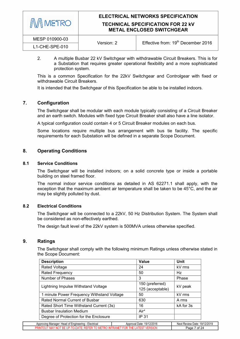
9. Ratings The Switchgear shall comply with the following minimum Ratings unless otherwise stated in the Scope Document:
Description Value Unit Rated Voltage 24 kV rms Rated Frequency 50 Hz Number of Phases 3 Phase
Lightning Impulse Withstand Voltage 150 (preferred) 125 (acceptable) kV peak
1 minute Power Frequency Withstand Voltage 50 kV rms Rated Normal Current of Busbar 630 A rms Rated Short Time Withstand Current (3s) 16 kA for 3s Busbar Insulation Medium Air* Degree of Protection for the Enclosure IP 31

ELECTRICAL NETWORKS SPECIFICATION TECHNICAL SPECIFICATION FOR 22 kV
METAL ENCLOSED SWITCHGEAR
MESP 010900-03 Version: 2 Effective from: 19th December 2016
L1-CHE-SPE-010
Approving Manager: Head of Engineering - Electrical Approval Date: 19/12/2016 Next Review Date: 19/12/2019 PRINTOUT MAY NOT BE UP-TO-DATE; REFER TO METRO INTRANET FOR THE LATEST VERSION Page 8 of 24
Description Value Unit Loss of Service Criticality class LSC 2B Class of Partitions PM Internal Arc Classification Type AFLR Internal Arc 16 kA for 1s Circuit Breaker Interrupter type Vacuum* Rated Normal Current of Circuit Breaker 630 A rms Rated Short Circuit Breaking Current of Circuit Breaker 16 kA rms
Rated Operating Sequence of Circuit Breaker 0–0.3s–CO–15s–CO
Maximum Opening Time of Circuit Breaker 100 ms No-Load Mechanical Endurance of Circuit Breaker M2 class Rated Electrical Endurance of Circuit Breaker E2 class Number of switching operations at rated short-circuit breaking current 100 operations
Number of Trip Coils 2 Rated Short Circuit Making Current of Earth Switch 40 kA peak Rated Mechanical Life of Earthing Switch 1,000 cycles Rated Electrical Endurance of Earth Switch E2 class
*SF6 type may be considered subject to further consultation with MTM regarding environmental concerns.
10. General Requirements
10.1 Modules The Switchgear shall consist of a number of individual Modules as specified. Each Module shall contain one Switching Device and one Earthing Device, along with its associated equipment as detailed below. Additional Modules shall be able to be added as required.
The specific requirements for each of these Modules are given below.
10.2 Enclosure The Switchgear and Controlgear shall be Metal-Enclosed. Each Module shall be partitioned. The Circuit Breaker, the Busbar, the Power Cable Termination and the Control and Protection System of each Module shall be metallically partitioned into separate Compartments.
Each Module shall be as compact as possible.
All metalwork shall be suitably prepared and painted to protect it against corrosion for the expected life of the equipment. All external surfaces shall be coloured beige (colour X43 in accordance with AS 2700S).
A lifting facility shall be provided.

ELECTRICAL NETWORKS SPECIFICATION TECHNICAL SPECIFICATION FOR 22 kV
METAL ENCLOSED SWITCHGEAR
MESP 010900-03 Version: 2 Effective from: 19th December 2016
L1-CHE-SPE-010
Approving Manager: Head of Engineering - Electrical Approval Date: 19/12/2016 Next Review Date: 19/12/2019 PRINTOUT MAY NOT BE UP-TO-DATE; REFER TO METRO INTRANET FOR THE LATEST VERSION Page 9 of 24
10.3 Control Voltage The control supplies for the 22kV Switchgear Assembly is generally provided from the Substation Battery supply that could be 50Vdc, 110Vdc or 125Vdc. The Control Voltage will be specified in the Scope Document.
The control supply shall be looped between panels and brought to terminals in the incomer feeder panel.
Three separate supplies shall be provided to the 22kV switchgear assembly:
• A supply for the Bus Protection, Primary Protection and the first trip coils of all the circuit breakers (supply to be looped between circuit breaker panels)
• A supply for the Backup Protection and the second trip coils of all the circuit breakers (supply to be looped between circuit breaker panels)
• A supply for panel indications which will be fed from the Substation battery supply. Refer Scope document for battery supply voltage.
AC auxiliary supply shall also be looped between panels and brought to terminals in the incomer feeder. The auxiliary supply shall be 230Vac and will be provided from the substation 415Vac switchboard. This shall be used only for the anti-condensation heaters.
10.4 Labelling All Modules, Switching Devices, control switches, components and indicators shall be labelled and have appropriate warning signs on the front and back of the panel. The external labels shall be of the Traffolyte type and shall be fastened by screws. Bus shutters shall be colour coded Yellow and line shutters shall be colour coded Red.
Each Module will be assigned a standard Operating Designation label. This will be supplied by MTM at Final Approval Stage. The Module shall be fitted with this label.
The Single Line Diagram for each module shall be permanently and indelibly shown on the front of the module.
The manufacturer shall obtain the device numbers from MTM prior to manufacture.
10.5 Anti-condensation Heaters An anti-condensation Heater shall be fitted in each Compartment of each Module.
If the manufacturer can demonstrate that this is not required, a submission shall be provided for consideration by MTM.
The Heaters shall be powered from the 230Vac supply of the Substation. A switch shall be provided in the Control Compartment to switch off the Heaters.
ELECTRICAL NETWORKS SPECIFICATION TECHNICAL SPECIFICATION FOR 22 kV
METAL ENCLOSED SWITCHGEAR
MESP 010900-03 Version: 2 Effective from: 19th December 2016
L1-CHE-SPE-010
Approving Manager: Head of Engineering - Electrical Approval Date: 19/12/2016 Next Review Date: 19/12/2019 PRINTOUT MAY NOT BE UP-TO-DATE; REFER TO METRO INTRANET FOR THE LATEST VERSION Page 10 of 24
10.6 SCADA Interface Each bus section of the switchgear shall be fitted with a SEL fibre optic transceiver type EIA 485 (SEL 2824) complete with required power supply. All required cabling for SCADA connections shall be made to the transceiver. 3xOC3 ST/ST fibre optic cabling shall be provided between the transceiver and the RTU. Each media converter should then be wired onto a RS485 copper bus connected to each Protection relay which is installed.
A single phase 230V 10A captive Socket outlet needs to be installed to the top left of each RTU
Minimum clearance of 600mm required to both sides of each RTU for access.
10.7 Prohibited Materials There shall be no asbestos or materials containing asbestos in the Switchgear and Controlgear. A statement certifying that the product is free of asbestos containing materials must be completed and signed, and delivered to MTM prior to despatch.
11. Busbar Requirements Each Module shall contain a single 22 kV Busbar System located in its designated Busbar Compartment which can be connected to the adjacent Modules. One Busbar Voltage Transformer and one Busbar Earthing Switch shall be provided for each combination of Modules. The Voltage Transformer and Earthing Switch shall be provided on the same Module.
11.1 Busbar Voltage Transformer and Bus Alive Indication A three phase Voltage Transformer shall be provided and connected to the Busbar for the purpose of providing an indication of the status of the Busbar, and for any protection schemes that require it. It can be a plug in type.
The Voltage Transformer shall comply with AS 60044.2: Instrument transformers - Inductive voltage transformers. It shall be rated at 50 VA, 22kV/110 V, Class 0.5 M, Voltage Factor 1.9 / 8h.
The Voltage Transformer shall have a rating plate fitted to the Transformer with an identical plate be affixed within the Control compartment so that it is readily able to be read.
Suitable instrument transformer fuse protection shall be provided for each phase on the primary side to protect the switchgear and the Voltage Transformer against possible faults.
A low voltage circuit breaker shall be provided on the secondary side of the Voltage Transformer. This shall be installed in the same compartment as the Transformer.
The secondary wiring from the Voltage Transformers shall be run separately from all other wiring, and shall be terminated on a separate terminal strip in the Control Compartment. The Voltage Transformer secondary neutral shall be connected as per the requirement of the protection relays.
It shall have a minimum cross-sectional area of 2.5mm2. Where 2.5mm2 is used, it shall have a stranding of 50/0.25mm, and the lugs shall be of the double grip ring pre-insulated crimp type.
The cable insulation shall be coloured according to the phase (red/white/blue/black).

ELECTRICAL NETWORKS SPECIFICATION TECHNICAL SPECIFICATION FOR 22 kV
METAL ENCLOSED SWITCHGEAR
MESP 010900-03 Version: 2 Effective from: 19th December 2016
L1-CHE-SPE-010
Approving Manager: Head of Engineering - Electrical Approval Date: 19/12/2016 Next Review Date: 19/12/2019 PRINTOUT MAY NOT BE UP-TO-DATE; REFER TO METRO INTRANET FOR THE LATEST VERSION Page 11 of 24
11.2 Busbar Earthing Switch A fixed, fault-make Earthing Switch shall be provided for earthing of the Busbar.
The Earthing Switch shall be mechanically or key interlocked with all the Modules. An interlocking diagram shall be provided in the Scope document. The Castell and Fortress type key interlocking systems are an acceptable system.
Requirements of section 12.2.1 “General Earthing Switch Requirements” shall apply to the Busbar Earth.
12. Power Cable Termination Requirements Each Module shall have a Power Cable Termination Compartment with interlock-controlled access.
The Compartment shall contain the Terminals for the connection of the external power cable, the Line Earthing Switch, and a Line Alive Detection System.
The terminals shall only be accessible when the Line Earthing Switch is closed.
The Compartment shall be suitable for the power cable to entering from below and shall allow power cable termination via the front of the assembly.
12.1 Terminal Requirements The Terminals shall be suitable for the connection of a terminated insulated cable. The cross-section area of the cable cores will be typically be in the range 50-185 mm2.
Appropriate brackets, clamps and gland plates shall be provided to adequately support the cables in the Compartment so that the weight of the conductor is not taken by the Terminals. The gland plates shall be 3.0mm Aluminium plate unless otherwise agreed in writing.
The height of the Terminal shall allow space for the 22kV cable termination within the Compartment and is typically 400mm.
A means shall be provided for insulation and phase testing of the Cable.
12.2 Line Earth Switch Requirements
12.2.1 General Earthing Switch Requirements The Earthing Switch shall be rated to close onto the fault rating of the Assembly and the closing action shall be operator independent.
Each Earthing Switch shall be provided with a mechanical indicating device to positively indicate whether it is in the OPEN OR EARTH position and the words "OPEN" and "EARTH" shall be used for the respective indication of these positions.
A padlock shall be provided to lock the Earth Switch into position and prevent the position from being changed. A window shall be provided for observing the position of the Earthing Switch contacts. Retro-reflective tape shall be installed on the Earth Switch blades to highlight the position of the blades. White light emitting diodes (LEDs) shall be fitted to provide appropriate internal illumination of the earthing switch.
ELECTRICAL NETWORKS SPECIFICATION TECHNICAL SPECIFICATION FOR 22 kV
METAL ENCLOSED SWITCHGEAR
MESP 010900-03 Version: 2 Effective from: 19th December 2016
L1-CHE-SPE-010
Approving Manager: Head of Engineering - Electrical Approval Date: 19/12/2016 Next Review Date: 19/12/2019 PRINTOUT MAY NOT BE UP-TO-DATE; REFER TO METRO INTRANET FOR THE LATEST VERSION Page 12 of 24
The light shall not form part of the high voltage zone containing the Earthing Switch and shall have ready and safe access for maintenance (lamp changing) from outside of the Assembly, without having to de-energise the Assembly. The lights shall be supplied by the substation battery and each light shall be fitted with a timed push button switch, ensuring that the light shall only be illuminated for a limited time period (range 1 to 5 mins).
12.2.2 Circuit Earthing Switch Each of the Circuit Breakers shall be provided with an Earthing Switch to earth the cable (power terminal) side of the switchgear.
The Earthing Switch shall be mechanically interlocked with the Circuit Breaker to prevent closing the Earth Switch on to live circuit. In the case of the Auxiliary Transformer supplies and Signal Transformer supplies the Circuit Breakers shall be also mechanically and/or electrically and/or key interlocked with the corresponding 415 v switch and 2200 v circuit breaker to prevent closure of earth switch on to “back feed”.
12.3 Line Alive and Bus Alive Detection System Requirements The Line Alive and Bus Alive Detection System shall detect the energised state of the Terminals.
It shall be in accordance with IEC 61243-5 Live working - Voltage detectors - Part 5: Voltage detecting systems and be provided on each phase. The use of a complying capacitive voltage detector is acceptable.
The System shall provide an indication on the front of the Control Compartment of the Module.
13. Circuit Breaker Module Requirements The Circuit Breaker will be used to connect to the Supply Feeders, Rectifier Units, Auxiliary Transformer and Signal Transformer at the Substation.
The Circuit Breaker Module shall be compartmented as specified in the General Requirements.
The Circuit Breaker can be fixed mounted, with an interlocked Disconnector to isolate the Power Cable Terminals from the Circuit Breaker or withdrawable type. Refer to the Scope document for the site specific requirement.
13.1 Circuit Breaker Requirements The Circuit Breaker shall be a three pole vacuum interrupter with the Ratings specified in Clause 9. SF6 type may be considered subject to further consultation with MTM regarding environmental concerns.
A mechanical indication of the status of the Circuit Breaker, and the state of the closing spring shall be provided on the front of the Module.
The Circuit Breaker shall be fitted with a non-resettable mechanical operations counter.
ELECTRICAL NETWORKS SPECIFICATION TECHNICAL SPECIFICATION FOR 22 kV
METAL ENCLOSED SWITCHGEAR
MESP 010900-03 Version: 2 Effective from: 19th December 2016
L1-CHE-SPE-010
Approving Manager: Head of Engineering - Electrical Approval Date: 19/12/2016 Next Review Date: 19/12/2019 PRINTOUT MAY NOT BE UP-TO-DATE; REFER TO METRO INTRANET FOR THE LATEST VERSION Page 13 of 24
There shall be a minimum of 6 normally open and 6 normally closed auxiliary contacts provided for control & indication purposes in addition to those required for the operation and local indication of the Circuit Breaker.
These contacts shall be of a reliable and robust design and have a current rating of 20A carrying and 5A break at the control voltage without arc quenching devices. They shall be easily adaptable to be either make or break contacts.
13.2 Circuit Breaker Operation The Circuit Breaker shall be able to be manually and electrically closed and opened.
The manual closing and opening shall be able to be performed from the front of the Module.
The electrical closing and opening shall be performed locally or by a remote control. The details are given in the Control Compartment Requirements
The control power supply shall be used for the electrical operations. The current required to operate shall not exceed 5A.
13.3 Disconnector Requirements (Fixed Circuit Breaker only) The Disconnector shall disconnect the Circuit Breaker from the Power Cable Terminals.
It shall be interlocked with the Circuit Breaker so that it cannot be opened when the Circuit Breaker is closed, and the Circuit Breaker cannot be closed with the Disconnector is open.
It shall also be interlocked with the Line Earthing Switch as specified in the Line Earthing Switch requirements.
13.4 Circuit Breaker Test Position (Withdrawable Circuit Breaker only) The Circuit Breaker shall have a test position which isolates the power circuit while keeping all control circuits connected. A mechanical indication of the position (Inserted/Test /Withdrawn) of the Circuit Breaker shall be provided on the front of the Module.
A padlock shall be provided to lock the Circuit Breaker into position and prevent the position from being changed.
Two spare auxiliary contacts shall be provided for each position.
13.5 Power Terminal Compartment Additional Requirements The Power Terminal Compartment shall be capable to house 2 sets of Protection Current Transformers on each Phase for the Protection System.
The Current Transformers shall comply with AS 60044-1: Instrument transformers - Current transformers.
The details of the Current Transformers will be supplied separately in the Scope Document.
The Current Transformers shall have rating plates fitted to the Transformer with an identical plate affixed within the Control Compartment so that it is easily read.
ELECTRICAL NETWORKS SPECIFICATION TECHNICAL SPECIFICATION FOR 22 kV
METAL ENCLOSED SWITCHGEAR
MESP 010900-03 Version: 2 Effective from: 19th December 2016
L1-CHE-SPE-010
Approving Manager: Head of Engineering - Electrical Approval Date: 19/12/2016 Next Review Date: 19/12/2019 PRINTOUT MAY NOT BE UP-TO-DATE; REFER TO METRO INTRANET FOR THE LATEST VERSION Page 14 of 24
13.6 Control Compartment Requirements The Control Compartment shall contain all of the low voltage control and protection components not mounted on the Circuit Breaker.
It shall be accessed by a non-lockable hinged, dustproof, sealed door. A stay shall be provided to enable the door to be held in the open position.
The Protection Relays, Indication Meters, Control Switches and Indicating Lights may be mounted on the door. When it is not mounted on the door, they shall be visible and accessible for control/interrogation without opening the door. All other equipment including the Master trip Relay shall be mounted inside the Compartment.
The control and auxiliary wiring terminations for connection to external circuits shall be located in a suitable position inside the compartment.
A separate terminal strip shall be provided for the protection CT secondary winding terminals.
Indicating Lights shall be provided for the Open and Closed indications of the Circuit Breaker. These shall be energized by dedicated and electrically isolated auxiliary contacts of the Circuit Breaker. Indicating lights shall be provided for the Line Alive Detection System and the Bus Alive Detection System.
All Indicating Lights shall be long life, high reliability type LED lights.
A single Switch shall be provided for the set of Modules to switch on and off the Indicating Lights. A Test Switch for the testing of all lights shall be provided.
The control and auxiliary terminals for connection to external circuits shall be provided at a convenient and accessible position inside the Control Compartment.
The terminals for the external SCADA cables shall be disconnect test terminals with test sockets. This is to facilitate the isolation of the SCADA cables for testing and faulty finding purposes of the input and output signals.
Push in terminals shall not be used and all terminals shall be screw in type.
13.7 Feeder Circuit Breaker Control System Requirements The Circuit Breaker, except for the Rectifier Unit Circuit Breaker, shall be locally electrically operated by a Control Switch on the Control Compartment door. It shall be a spring return to neutral type with a distinctive handle.
It shall also be operated by the SCADA System. Interposing relays for closing and for opening shall be provided in the Compartment. The voltage of the coil of the relay shall be rated as specified in the Scope Document.
For fixed mounted Circuit Breakers; it shall have a two position C & I Isolating Switch on the Control Compartment door to isolate the control and indication function of the Circuit Breaker from the SCADA RTU. The Switch positions shall be labelled “Isolated” and “Normal”. The escutcheon on the Switch shall be coloured yellow.

ELECTRICAL NETWORKS SPECIFICATION TECHNICAL SPECIFICATION FOR 22 kV
METAL ENCLOSED SWITCHGEAR
MESP 010900-03 Version: 2 Effective from: 19th December 2016
L1-CHE-SPE-010
Approving Manager: Head of Engineering - Electrical Approval Date: 19/12/2016 Next Review Date: 19/12/2019 PRINTOUT MAY NOT BE UP-TO-DATE; REFER TO METRO INTRANET FOR THE LATEST VERSION Page 15 of 24
13.8 Rectifier Unit Circuit Breaker Control System Requirements For fixed mounted Circuit Breakers; the Rectifier Circuit Breaker shall have a two position Rectifier Control Isolating Switch on the Control Compartment door to isolate the control and indication function of the Circuit Breaker from the Rectifier Unit Control & Protection System. The Switch positions shall be labelled “Isolated” and “Normal”. The escutcheon on the Switch shall be coloured yellow.
The Rectifier Circuit Breaker shall have a local Test Switch on the Control Compartment door. It shall be interlocked with the Circuit Breaker’s Disconnector and Rectifier Control Isolating Switch. It shall be a spring return to neutral type with a distinctive handle.
13.9 Protection Scheme Requirements The details of the Protection Scheme and Protection Relays for each Circuit Breaker Module will be specified in the Scope Document.
The Protection Relay associated with a Circuit Breaker may be mounted on the Control Compartment door.
The optical arc protection shall be RMS 1S20 or equivalent.
The Test Links shall be connected to each of the Current Transformer connections to the Relay, and to the main Tripping Contacts of the Relay.
The preferred Test Terminals are Weidmuller tyle WTL6/1/STB – part no. 1016900000 or equivalent.
The protection and metering CTs shall be tested by a NATA accredited laboratory unless agreed to in writing with MTM.
13.10 Control Wiring Requirements
13.10.1 Control and Auxiliary Wiring All control and auxiliary wiring shall be arranged as simply as possible so that the course of every conductor may be readily traced.
All wiring shall not be less than 1.5 mm2 stranded copper conductors unless otherwise agreed in writing.
For control wiring supplied from the substation battery, no single insulated conductor shall be in direct contact with earthed metal work.
13.10.2 Current Transformer and Voltage Transformer Wiring The secondary wiring from the Current Transformers shall be run separately from all other secondary wiring to the terminal strip in the control compartment.
Current Transformer (CT) and Voltage Transformer (VT) secondary wiring shall be a minimum size of 2.5mm2 and coloured according to the colour of the respective phase (red/white/blue/black). Where 2.5mm2 wiring is used it shall have a stranding of 50/0.25mm. All wiring connections to CTs, VTs and to protection relays shall be made using double grip ring type pre-insulated crimp lugs.
ELECTRICAL NETWORKS SPECIFICATION TECHNICAL SPECIFICATION FOR 22 kV
METAL ENCLOSED SWITCHGEAR
MESP 010900-03 Version: 2 Effective from: 19th December 2016
L1-CHE-SPE-010
Approving Manager: Head of Engineering - Electrical Approval Date: 19/12/2016 Next Review Date: 19/12/2019 PRINTOUT MAY NOT BE UP-TO-DATE; REFER TO METRO INTRANET FOR THE LATEST VERSION Page 16 of 24
13.10.3 Auxiliary Terminals Terminals for the connection of the control and auxiliary wiring to external circuits shall be provided at a suitably accessible position in the Assembly.
The arrangement of the wiring at the terminals shall be reviewed by the Client before the Assembly is wired.
Terminals for the connection of the control and auxiliary wiring to external circuits shall not be located in the HV compartment.
Provision shall be made for running the external cable to the terminals that is separated from other internal cabling and connections.
13.10.4 Current Transformer and Voltage Transformer Test Terminals Disconnect Test terminals shall be provided to facilitate:
- testing of the current transformers and voltage transformers
- secondary injection testing of the protection relays or measuring instruments (it shall be possible to test each device independently)
- isolation of the protection relay input and output signals
The preferred terminals are Weidmuller type: WTL6/1/STB- part No.1016900000.
The Disconnect Test terminals for the current transformer circuits shall be fitted with the appropriate cross connection sliders (for this terminal type) for shorting out the current transformer secondary windings.
13.10.5 Protection Relays Disconnect Test links shall be provided on all trip contacts of Protection Relays
13.10.6 SCADA Disconnect Test Terminals Suitable Disconnect Test terminals shall be provided for the connection of the SCADA cables, to facilitate isolation of the SCADA supply to the equipment, and shall have suitable test sockets for testing of the equipment input and output signals for SCADA control and monitoring.
14. Testing
14.1 Type Test The Switchgear shall have Type Test Certificates complying with Standard AS 62271. The Certificates shall include oscillograms and drawings of the test circuit. Copies of these Certificates shall be supplied with the tender documentation.
ELECTRICAL NETWORKS SPECIFICATION TECHNICAL SPECIFICATION FOR 22 kV
METAL ENCLOSED SWITCHGEAR
MESP 010900-03 Version: 2 Effective from: 19th December 2016
L1-CHE-SPE-010
Approving Manager: Head of Engineering - Electrical Approval Date: 19/12/2016 Next Review Date: 19/12/2019 PRINTOUT MAY NOT BE UP-TO-DATE; REFER TO METRO INTRANET FOR THE LATEST VERSION Page 17 of 24
14.2 Routine Tests The Switchgear and Controlgear shall be subjected to Routine Tests at the Manufacturer’s Workshop complying with AS 62271.
MTM reserves the right to appoint a representative to witness these Tests. Seven working days’ notification shall be given to MTM of intention to carry out factory testing.
The results of all Routine Tests shall be recorded on test certificates. The test certificates shall clearly show the performance of the equipment and shall be accompanied by tables showing the actually measured values and all calculations.
The test certificates shall be forwarded to MTM and the results approved by MTM prior to delivery.
15. Documentation and Support The Supplier must supply all materials, special tools and documents for the Switchgear and Controlgear. The documents shall contain all necessary information and instructions required for operation and maintenance of items.
15.1 Documentation Requirements All documentation shall be provided in English.
One electronic and eight paper copies of the each final document shall be provided and the content shall be identical in each copy.
Every page of the documentation shall be clearly identified in relation to the document to which it belongs and the version of that document. All pages of multi-page documents shall be uniquely numbered. It shall be possible to readily determine if all pages of a document are present.
Manuals shall be A4 size and shall be bound in durable covers or in 4-D ring binders.
15.2 Design Drawings The following drawings must be supplied:
i. Construction details of the Switchgear and Controlgear including dimensions.
ii. Physical layout and arrangement of the components of the Switchgear and Controlgear.
iii. Physical layout and arrangement of the Circuit Breaker and Switch – Fuse Modules.
iv. Physical layout and arrangement of the Earthing Switches.
v. The interlocking arrangement of the Switching Devices, Disconnectors and Earthing Switches.
vi. Mounting requirements for the Switchgear.
vii. Control circuit diagrams of the Circuit Breaker.
viii. Physical layout and arrangement of the Power Cable Connections.
ix. Details of control, protection and auxiliary wiring terminations.
x. Details of the Protection System.
ELECTRICAL NETWORKS SPECIFICATION TECHNICAL SPECIFICATION FOR 22 kV
METAL ENCLOSED SWITCHGEAR
MESP 010900-03 Version: 2 Effective from: 19th December 2016
L1-CHE-SPE-010
Approving Manager: Head of Engineering - Electrical Approval Date: 19/12/2016 Next Review Date: 19/12/2019 PRINTOUT MAY NOT BE UP-TO-DATE; REFER TO METRO INTRANET FOR THE LATEST VERSION Page 18 of 24
xi. Details of manual operation of the equipment and any tools to be provided.
xii. All other drawings required for Installation, Testing, Commissioning, Operation and Maintenance
The drawings shall be submitted for MTM approval prior to manufacturing.
15.3 Drawing Format All drawings must comply with VRIOGS 007.2 - Infrastructure Drafting Standard.
Files shall be provided in Microstation format on a compact disk (CD).
15.4 Technical Maintenance Plan A Technical Maintenance Plan which establishes the maintenance policy for the Switchgear as recommended by the Supplier shall be provided. This shall detail the preventative servicing schedules and maintenance intervals for all components. The servicing schedules shall reference appropriate detailed instructions in the maintenance manual.
The Technical Maintenance Plan shall contain a list of any recommended spare parts, detailing price, supplier and procurement lead-times.
The Technical Maintenance Plan shall detail safe disposal procedures applicable for when the Assembly is no longer serviceable (recycling, hazardous waste etc.).
15.5 Maintenance Manual The Maintenance Manual shall detail:
a) The theory of operation of the equipment.
b) All servicing activities.
c) Overhaul instructions.
d) Adjustment procedures.
e) The changing of components for repairs.
f) Fault-finding procedures.
g) The spares support schedule.
The Maintenance Manual shall also include a complete set of as-built drawings and a comprehensive parts list for the Assembly.
15.6 Installation Instructions Manual Installation Instructions Manual shall enable the Switchgear to be properly installed, tested and commissioned. This shall include all necessary drawings, and information regarding the storage, handling, loading and off-loading instructions.
15.7 Operating Instructions Manual The Operating Instructions Manual shall clearly describe the required procedures for physically operating all of the components of the Switchgear.
The operating procedures shall be consistent with the PTC Train Infrastructure Electrical Safety Rules (High Voltage Rules) (IPGOR-01).

ELECTRICAL NETWORKS SPECIFICATION TECHNICAL SPECIFICATION FOR 22 kV
METAL ENCLOSED SWITCHGEAR
MESP 010900-03 Version: 2 Effective from: 19th December 2016
L1-CHE-SPE-010
Approving Manager: Head of Engineering - Electrical Approval Date: 19/12/2016 Next Review Date: 19/12/2019 PRINTOUT MAY NOT BE UP-TO-DATE; REFER TO METRO INTRANET FOR THE LATEST VERSION Page 19 of 24
15.8 Tools & Equipment A complete set of operating tools and any other equipment necessary to operate and maintain the Switchgear and Controlgear shall be provided. This shall include any special devices required to test the Switchgear and Controlgear. Storage facilities for the tools and equipment shall also be provided.
The software and a PC interface for loading and downloading of Protection Relay settings and the latest fault current data to a laptop PC shall be provided. This shall include all peripheral interfacing equipment and connection cables necessary to connect and communicate with the system.
Any special lifting and installation equipment shall be supplied with the Switchgear.
16. Information to be Supplied in Scope Document The following is a summary of the information to be supplied in the Scope Document to make the Supply of the Switchgear and Controlgear to this Specification complete.
Number Item 1 Configuration of the Switchgear and Controlgear
2 Supporting Single Line Diagram
3 Control Voltage
4 Protection Current Transformers details
5 Protection Scheme and Protection Relays
6 Interlocking Diagram
ELECTRICAL NETWORKS SPECIFICATION TECHNICAL SPECIFICATION FOR 22 kV
METAL ENCLOSED SWITCHGEAR
MESP 010900-03 Version: 2 Effective from: 19th December 2016
L1-CHE-SPE-010
Approving Manager: Head of Engineering - Electrical Approval Date: 19/12/2016 Next Review Date: 19/12/2019 PRINTOUT MAY NOT BE UP-TO-DATE; REFER TO METRO INTRANET FOR THE LATEST VERSION Page 20 of 24
Appendix A – Design Management Requirements This Appendix describes the documentation which should be provided as a minimum at each stage of the procurement process. The documentation shall comply with the specifications above.
Tender Submission The following documents shall be provided as part of the tender submission:
• Pamphlets detailing the operating and interlocking principles of the Switchgear and Controlgear.
• A General Arrangement drawing of the Switchgear which clearly shows:
o The overall dimensions of the Switchgear and each Module.
o Details of the proposed cable terminals and cable entry requirements
• Type Test Certificates
• The Technical Data Schedule in Appendix B filled in.
• A list of recommended spare parts.
Contract Documentation One set of PDF copies of the drawings and documentation detailed in Clause 16, including any other information considered necessary for completeness shall be provided for review and approval by MTM four weeks after the Contact Award Date.
No manufacture shall commence until the drawings have been approved. An allowance of seven working days should be made by the Supplier for the review and approval of submitted documents.
A draft Installation Instructions Manual shall also be included.
Pre-Delivery Documentation Prior to delivery, the Supplier shall provide the paper and electronic copies of the Manuals, Drawings and Routine Test Certificates.
ELECTRICAL NETWORKS SPECIFICATION TECHNICAL SPECIFICATION FOR 22 kV
METAL ENCLOSED SWITCHGEAR
MESP 010900-03 Version: 2 Effective from: 19th December 2016
L1-CHE-SPE-010
Approving Manager: Head of Engineering - Electrical Approval Date: 19/12/2016 Next Review Date: 19/12/2019 PRINTOUT MAY NOT BE UP-TO-DATE; REFER TO METRO INTRANET FOR THE LATEST VERSION Page 21 of 24
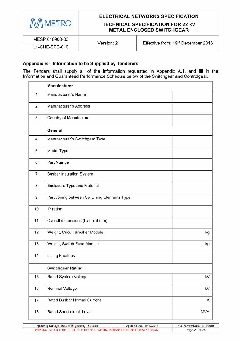
Appendix B – Information to be Supplied by Tenderers The Tenders shall supply all of the information requested in Appendix A.1, and fill in the Information and Guaranteed Performance Schedule below of the Switchgear and Controlgear.
Manufacturer
1 Manufacturer’s Name
2 Manufacturer’s Address
3 Country of Manufacture
General
4 Manufacturer’s Switchgear Type
5 Model Type
6 Part Number
7 Busbar Insulation System
8 Enclosure Type and Material
9 Partitioning between Switching Elements Type
10 IP rating
11 Overall dimensions (l x h x d mm)
12 Weight, Circuit Breaker Module kg
13 Weight, Switch-Fuse Module kg
14 Lifting Facilities
Switchgear Rating
15 Rated System Voltage kV
16 Nominal Voltage kV
17 Rated Busbar Normal Current A
18 Rated Short-circuit Level MVA

ELECTRICAL NETWORKS SPECIFICATION TECHNICAL SPECIFICATION FOR 22 kV
METAL ENCLOSED SWITCHGEAR
MESP 010900-03 Version: 2 Effective from: 19th December 2016
L1-CHE-SPE-010
Approving Manager: Head of Engineering - Electrical Approval Date: 19/12/2016 Next Review Date: 19/12/2019 PRINTOUT MAY NOT BE UP-TO-DATE; REFER TO METRO INTRANET FOR THE LATEST VERSION Page 22 of 24
19 Rated Frequency Hz
20 Phases
21 Rated Lightning Impulse Withstand Voltage kV
22 Rated short-duration Power-frequency Withstand Voltage kV
Circuit Breaker
22 Manufacturer
23 Model Type
24 Interrupter Type
25 Rated Normal current A
26 Rated short circuit Breaking Current kA
27 Rated short circuit Making Current kA
28 Operating Sequence
29 Rated supply voltage of closing and opening devices V
Switch - Fuse
30 Manufacturer
31 Model Type
32 Interrupter Type
33 Rated Normal current A
34 Rated short circuit Breaking Current kA
35 Rated short circuit Making Current kA
36 Fuse Type
37 Rated supply voltage of closing and opening devices V
ELECTRICAL NETWORKS SPECIFICATION TECHNICAL SPECIFICATION FOR 22 kV
METAL ENCLOSED SWITCHGEAR
MESP 010900-03 Version: 2 Effective from: 19th December 2016
L1-CHE-SPE-010
Approving Manager: Head of Engineering - Electrical Approval Date: 19/12/2016 Next Review Date: 19/12/2019 PRINTOUT MAY NOT BE UP-TO-DATE; REFER TO METRO INTRANET FOR THE LATEST VERSION Page 23 of 24
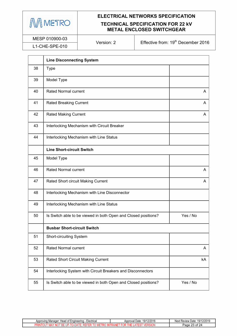
Line Disconnecting System
38 Type
39 Model Type
40 Rated Normal current A
41 Rated Breaking Current A
42 Rated Making Current A
43 Interlocking Mechanism with Circuit Breaker
44 Interlocking Mechanism with Line Status
Line Short-circuit Switch
45 Model Type
46 Rated Normal current A
47 Rated Short circuit Making Current A
48 Interlocking Mechanism with Line Disconnector
49 Interlocking Mechanism with Line Status
50 Is Switch able to be viewed in both Open and Closed positions? Yes / No
Busbar Short-circuit Switch
51 Short-circuiting System
52 Rated Normal current A
53 Rated Short Circuit Making Current kA
54 Interlocking System with Circuit Breakers and Disconnectors
55 Is Switch able to be viewed in both Open and Closed positions? Yes / No

ELECTRICAL NETWORKS SPECIFICATION TECHNICAL SPECIFICATION FOR 22 kV
METAL ENCLOSED SWITCHGEAR
MESP 010900-03 Version: 2 Effective from: 19th December 2016
L1-CHE-SPE-010
Approving Manager: Head of Engineering - Electrical Approval Date: 19/12/2016 Next Review Date: 19/12/2019 PRINTOUT MAY NOT BE UP-TO-DATE; REFER TO METRO INTRANET FOR THE LATEST VERSION Page 24 of 24
Indication and Protection Systems
56 Line Protection Relay Manufacturer
57 Relay Model
58 Current Transformer Manufacturer & Type
59 Current Transformer Ratios
60 Voltage Transformer Manufacture & Type
61 Voltage Transformer Ratings
62 Bus Protection Scheme
63 Bus Protection Device Manufacturer
64 Device Type and Model