MEMORANDUM OF AGREEMENT BETWEEN THE Documents/5p/CG...related to drilling, production, completion,...
14
MEMORANDUM OF AGREEMENT BETWEEN THE MINERALS MANAGEMENT SERVICE- U.S. DEPARTMENT OF THE INTERIOR AND THE U.S. COAST GUARD - U.S. DEPARTMENT OF HOMELAND SECURITY MMS/USCG MOA: OCS-04 Effective Date: 28 February 2008 SUBJECT: FLOATING OFFSHORE FACILITIES A. PURPOSE The purpose of this Memorandum of Agreement (MOA) is to identify and clarify responsibilities of the Minerals Management Service (MMS) and the U.S. Coast Guard (USCG) and to provide guidance for the appropriate agency approval of systems and sub-systems for floating offshore facilities. For the purposes of this MOA a floating offshore facility is defined as: 1) a buoyant facility that is permanently or temporarily attached to the seabed of the Outer Continental Shelf (OCS), or 2) that dynamically holds position over the OCS and is attached only via flow-lines, umbilicals or similar connections; these facilities are installed for the purpose of exploring for, developing, producing, transporting via pipeline, storing or processing minerals resources from the OCS. This term includes, but is not limited to, tension leg platforms, spars, semi-submersibles and shipshape hulls. For the purposes of this MOA, the term does not include derrick barges, floatels, tenders, mobile offshore drilling units or floating offshore facilities covered by the Deepwater Port Act which are the primary responsibility of the USCG and the Maritime Administration and regulated under the authority of 33 Code of Federal Regulations (CFR) Subchapter NN - Deepwater Ports. This MOA updates Section 1 (Communications and Contacts) and replaces parts of Section 7 (Offshore Facilities System/Sub-system Responsibility Matrix) regarding floating offshore facilities of MMS/USCG MOA OCS-01: Agency Responsibilities, dated 30 September 2004. Implementation of this MOA will be in accordance with Section J (Memorandum of Agreements - Development and Implementation) of the Memorandum of Understanding (MOU) between the MMS and USCG, dated 30 September 2004. The participating agencies will review their internal procedures and, where appropriate, revise them to accommodate the provisions of this MOA. B. STATUTORY AUTHORITIES The USCG and MMS enter this agreement under authority of Title 14 United States Code (USC) § 141 - Coast Guard Cooperation with other Agencies; 43 USC § 1331 et seq. - the Outer Continental Shelf Lands Act (OCSLA); 33 USC§ 1321(j)- the Federal Water Pollution Control Act; and the Maritime Transportation Security Act of 2002 as codified in 46 USC, Chapter 701.
Transcript of MEMORANDUM OF AGREEMENT BETWEEN THE Documents/5p/CG...related to drilling, production, completion,...
MEMORANDUM OF AGREEMENT
BETWEEN THE
MINERALS MANAGEMENT SERVICE- U.S. DEPARTMENT OF THE INTERIOR
AND THE
U.S. COAST GUARD - U.S. DEPARTMENT OF HOMELAND SECURITY
MMS/USCG MOA: OCS-04 Effective Date: 28 February 2008
SUBJECT: FLOATING OFFSHORE FACILITIES
A. PURPOSE
The purpose of this Memorandum of Agreement (MOA) is to identify and clarify responsibilities of the Minerals Management Service (MMS) and the U.S. Coast Guard (USCG) and to provide guidance for the appropriate agency approval of systems and sub-systems for floating offshore facilities. For the purposes of this MOA a floating offshore facility is defined as: 1) a buoyant facility that is permanently or temporarily attached to the seabed of the Outer Continental Shelf (OCS), or 2) that dynamically holds position over the OCS and is attached only via flow-lines, umbilicals or similar connections; these facilities are installed for the purpose of exploring for, developing, producing, transporting via pipeline, storing or processing minerals resources from the OCS. This term includes, but is not limited to, tension leg platforms, spars, semi-submersibles and shipshape hulls. For the purposes of this MOA, the term does not include derrick barges, floatels, tenders, mobile offshore drilling units or floating offshore facilities covered by the Deepwater Port Act which are the primary responsibility of the USCG and the Maritime Administration and regulated under the authority of 33 Code of Federal Regulations (CFR) Subchapter NN -Deepwater Ports.
This MOA updates Section 1 (Communications and Contacts) and replaces parts of Section 7 (Offshore Facilities System/Sub-system Responsibility Matrix) regarding floating offshore facilities of MMS/USCG MOA OCS-01: Agency Responsibilities, dated 30 September 2004. Implementation of this MOA will be in accordance with Section J (Memorandum of Agreements Development and Implementation) of the Memorandum of Understanding (MOU) between the MMS and USCG, dated 30 September 2004. The participating agencies will review their internal procedures and, where appropriate, revise them to accommodate the provisions of this MOA.
B. STATUTORY AUTHORITIES
The USCG and MMS enter this agreement under authority of Title 14 United States Code (USC) §141 - Coast Guard Cooperation with other Agencies; 43 USC § 1331 et seq. - the Outer Continental Shelf Lands Act (OCSLA); 33 USC§ 1321(j)- the Federal Water Pollution Control Act; and the Maritime Transportation Security Act of 2002 as codified in 46 USC, Chapter 701.
Applicable MMS regulations are found at 30 CFR, Subchapter B - Offshore, Part 250 - Oil and Gas and Sulphur Operations in the Outer Continental Shelf.
Applicable USCG regulations are found under 33 CFR, Subchapter N - Outer Continental Shelf Activities, Parts 140-147 and applicable parts of 46 CFR- Shipping and 33 CPR Chapter I, Subchapter H - Maritime Security.
C. JURISDICTION
The MMS, within the U.S. Department of the Interior (DOI), is responsible for managing the nation's natural gas, oil, and other mineral resources on the OCS in a safe and environmentally sound manner. Under the OCSLA and other authorities, the MMS regulates activities such as exploration, drilling, completion, development, production, pipeline transportation, storage, well servicing, and workover activities under its jurisdiction. MMS also grant rights-of-use and easements to construct and maintain facilities, and rights-of-ways for sub-sea pipelines, umbilicals, or other equipment.
The USCG, within the U.S. Department of Homeland Security (DHS), is responsible for protecting the marine environment, promoting the safety of life and property and ensuring security on the OCS. Under OCSLA, 33 CFR Subchapter N - Outer Continental Shelf Activities, and Title 46 USC - Shipping and Title 46 CPR, as well as other authorities, the USCG regulates OCS facilities, mobile offshore drilling units (MODUs) and vessels engaged in OCS activities, including, but not limited to, tank vessels, offshore supply vessels, and other vessels involved in OCS activities or transfers of certain cargoes.
D. AGENCY RESPONSIBILITIES
1. COMMUNICATIONS AND CONTACTS
The participating agencies will identify in writing appropriate representatives for the purposes of keeping each other timely informed of issues, relevant applications, routine policy determinations, and to coordinate joint activities. For the USCG, the Assistant Commandant for Marine Safety, Security and Stewardship is responsible for identifying that representative. For MMS, the Associate Director of Offshore Minerals Management is responsible for identifying that representative.
These representatives will maintain an accurate and updated list of contacts for their respective agency and will make notifications to their counterpart of any changes to agency representatives.
Designation of agency representatives by function:
USCG MMS Headquarters Chief, Vessel & Facility
Operating Standards (CG-5222)
MMS Agency Liaison to the Coast Guard
2
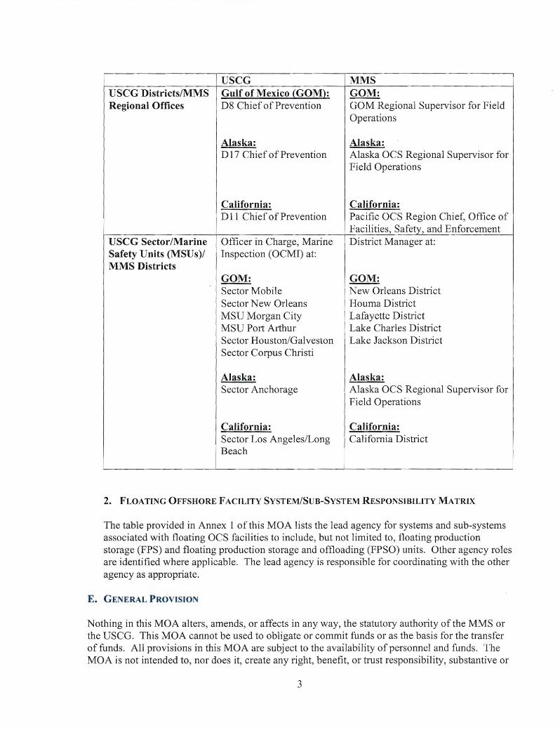
USCG Districts/MMS Regional Offices
USCG Gulf of Mexico (GOM): D8 Chief of Prevention
MMS GOM: GOM Regional Supervisor for Field Operations
Alaska: D 17 Chief of Prevention
Alaska: Alaska OCS Regional Supervisor for Field Operations
USCG Sector/Marine Safety Units (MSU s )/ MMS Districts
California: D 11 Chief of Prevention
Officer in Charge, Marine Inspection ( OCMI) at:
GOM: Sector Mobile Sector New Orleans MSU Morgan City MSU Port Arthur Sector Houston/Galveston Sector Corpus Christi
California: Pacific OCS Region Chief, Office of Facilities, Safety, and Enforcement District Manager at:
GOM: New Orleans District Houma District Lafayette District Lake Charles District Lake Jackson District
Alaska: Sector Anchorage
Alaska: Alaska OCS Regional Supervisor for Field Operations
California: Sector Los Angeles/Long Beach
California: California District
2. FLOATING OFFSHORE FACILITY SYSTEM/SUB-SYSTEM RESPONSIBILITY MATRIX
The table provided in Annex 1 of this MOA lists the lead agency for systems and sub-systems associated with floating OCS facilities to include, but not limited to, floating production storage (FPS) and floating production storage and offloading (FPSO) units. Other agency roles are identified where applicable. The lead agency is responsible for coordinating with the other agency as appropriate.
E. GENERAL PROVISION
Nothing in this MOA alters, amends, or affects in any way, the statutory authority of the MMS or the USCG. This MOA cannot be used to obligate or commit funds or as the basis for the transfer of funds. All provisions in this MOA are subject to the availability ofpersonnel and funds. The MOA is not intended to, nor does it, create any right, benefit, or trust responsibility, substantive or
3
procedural, enforceable at law or equity by any person or party against the United States, its agencies, its officers, or any other person. This MOA neither expands nor is in derogation of those powers and authorities vested in the participating agencies by applicable law. It is the intent of the parties that the MOA remain in force even if a portion of it is determined to be unlawful, provided the remaining portion can be read coherently and understood.
F. AMENDMENTS TO THE MOA
This MOA may be amended by mutual agreement of the participating agencies as described in Section J of the MMS/USCG MOU dated 30 September 2004.
G. TERMINATION
The MOA may be terminated upon a 30-day advance written notification.
Chris C. Oynes Associate Director Offshore Minerals Management Minerals Management Service U.S. Department of the Interior
Rear Admiral Brian M. Salemo Assistant Commandant for Marine Safety, Security and Stewardship U.S. Coast Guard U.S. Department of Homeland Security
4
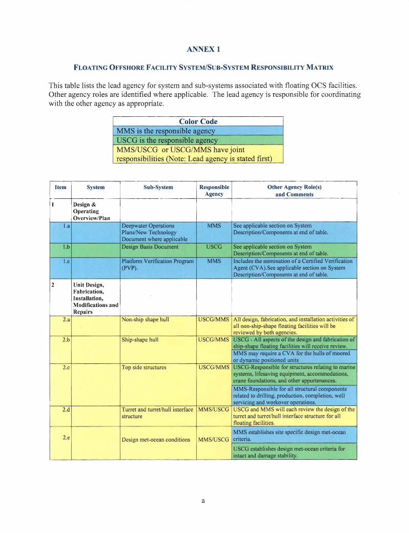
ANNEX 1
FLOATING OFFSHORE FACILITY SYSTEM/SUB-SYSTEM RESPONSIBILITY MATRIX
This table lists the lead agency for system and sub-systems associated with floating OCS facilities. Other agency roles are identified where applicable. The lead agency is responsible for coordinating with the other agency as appropriate.
Color Code
Item System Sub-System Responsible Agency
Other Agency Role(s) and Comments
1 Design & Operating Overview/Plan
I.a Deepwater Operations Plans/New Technology Document where applicable
MMS See applicable section on System Description/Components at end of table.
1.b Design Basis Document USCG See applicable section on System Description/Components at end of table.
l.c Platform Verification Program (PVP).
MMS Includes the nomination of a Certified Verification Agent (CVA).See applicable section on System Description/Components at end of table.
2 Unit Design, Fabrication, Installation, Modifications and Repairs
2.a ~
Non-ship shape hull USCG/MMS All design, fabrication, and installation activities of all non-ship-shape floating facili ties will be reviewed by both agencies.
2.b
11 I
~
Ship-shape hull
~
-
USCG/MMS
II
USCG - All aspects of the design and fabrication of ship-shape floating facilities will receive review. MMS may require a CVA for the hulls of moored or dynamic positioned units
2.c
rn I
ll
Top side structures
~
USCG/MMS
II
USCG-Responsible for structures relating to marine systems, lifesaving equipment, accommodations, crane foundations, and other appurtenances.
MMS-Responsible for all structural components related to drilling, production, completion, well servicing and workover operations.
2.d - - - Turret and turret/hull interface structure
MMS/USCG USCG and MMS will each review the design of the turret and turret/hull interface structure for all floating facilities.
2.e
u
)c;;
-
II I
-· -
- -
Design met-ocean conditions
(
'!::::
- -
MMS/USCG
-MMS establishes site specific design met-ocean criteria.
USCG establishes design met-ocean criteria for intact and damage stability.
a
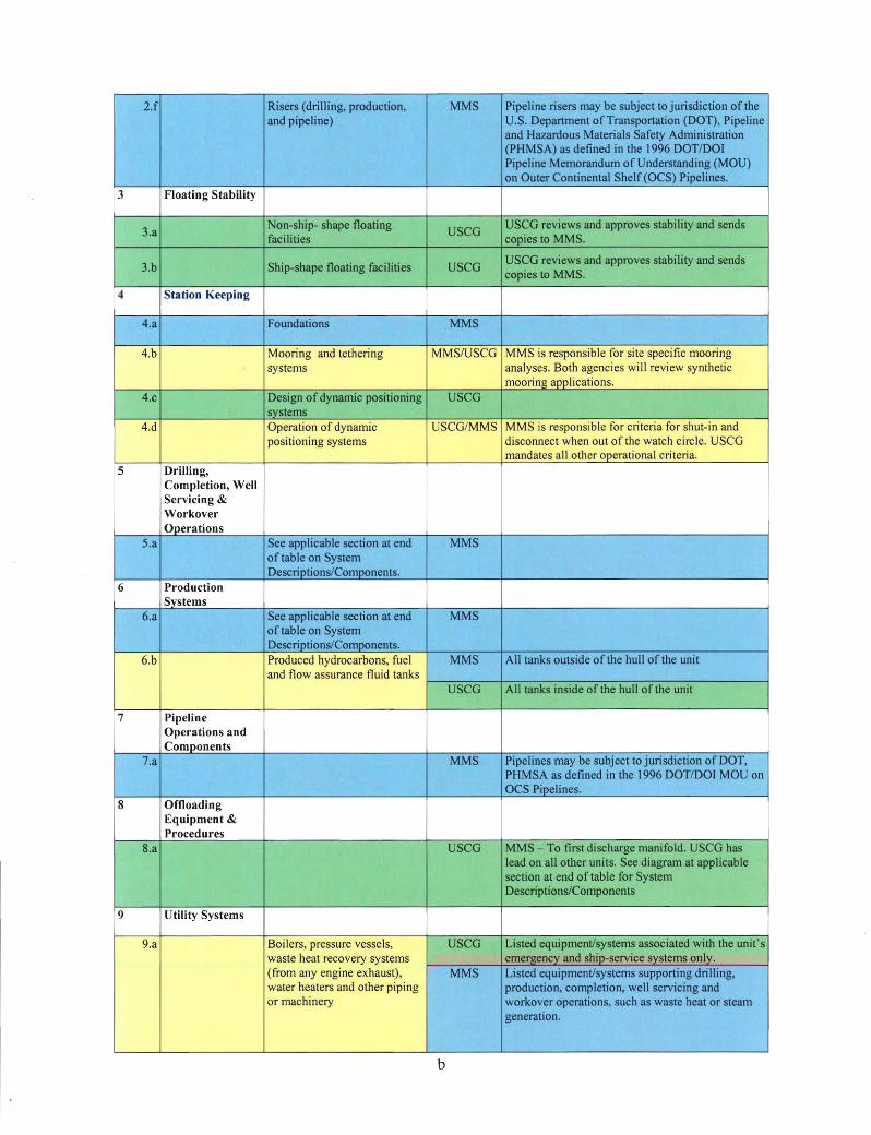
2.f Risers (drilling, production, MMS Pipeline risers may be subject to jurisdiction of the and pipeline) U .S. Department of Transportation (DOT), Pipeline
and Hazardous Materials Safety Administration (PHMSA) as defined in the 1996 DOT/DOI Pipeline Memorandum of Understanding (MOU) on Outer Continental Shelf (OCS) Pipelines.
3 Floating Stability
3.a Non-ship- shape floating
USCG USCG reviews and approves stability and sends
facilities copies to MMS.
3.b Ship-shape floating facilities USCG USCG reviews and approves stability and sends copies to MMS.
4 Station Keeping
4.a Foundations MMS
4.b =---'= Mooring and retheri ng MMS/USCG MMS is responsible for site specific mooring
~ systems analyses. Both agencies will review synthetic
mooring applications. 4.c Design of dynamic positioning USCG
systems - -4.d Operation of dynamic uSCG/MMS MMS is responsible for criteria for shut-in and
positioning systems disconnect when out of the watch circle. USCG mandates all other operational criteria.
5 Drilling, Completion, Well Servicing & Workover Operations
5.a See applicable section at end MMS of table on System Descriptions/Components.
6 Production Systems
6.a See applicable section at end MMS of table on System Descriptions/Components.
6.b - ~~ = Produced hydrocarbons, fuel MMS All tanks outside of the hull of the unit and flow assurance fluid tanks
I r-!J I' USCG All tanks inside of the hull of the unit - :=::_
7 Pipeline Operations and Components
7.a MMS Pipelines may be subject to jurisdiction of DOT, PHMSA as defined in the 1996 DOT/DOI MOU on OCS Pipelines.
8 Offloading Equipment & Procedures
8.a USCG MMS - To first discharge manifold. USCG has lead on all other units. See diagram at applicable section at end of table for System Descriptions/Components
9 Utility Systems
9.a Boilers, pressure vessels, USCG Listed equipment/systems associated with the unit' s j
waste heat recovery systems emergency and ship-service systems only.
·~' (from any engine exhaust), MMS Listed equipment/systems supporting drilling,
I water heaters and other piping production, completion, well servicing and
I? or machinery workover operations such as waste heat or steam
' generation.
I
......... -
b
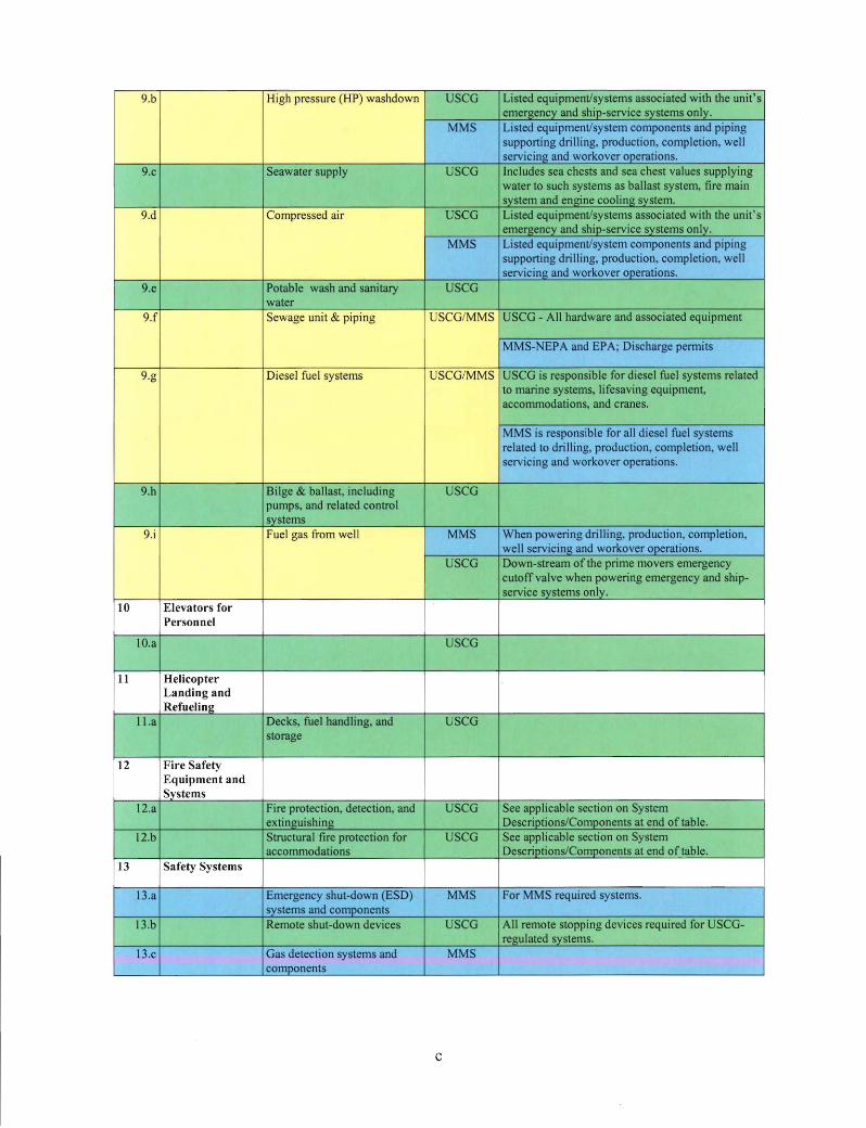
9.b - - High pressure (HP) washdown USCG Listed equipment/systems associated with the unit' s
r emergency and ship-service systems only. I MMS Listed equipment/system components and piping
~; ~
supporting drilling, production, completion, welln
- - servicing and workover operations. 9.c Seawater supply USCG Includes sea chests and sea chest values supplying
water to such systems as ballast system, fire main system and engine cooling system.
9.d Compressed air USCG Listed equipment/systems associated with the unit's emergency and ship-service systems only.
I
~II MMS Listed equipment/system components and piping ' 11 ' supporting drilling, production, completion, well
~ servicing and workover operations. 9.e Potable wash and sanitary USCG
water 9.f ii r Sewage unit & piping - l3 SCG/MMS USCG - All hardware and associated equipment
d ~ MMS-NEPA and EPA; Discharge permits ~
9.g - Diesel fuel systems - - USCG/MMS USCG is responsible for diesel fuel systems related
~J to marine systems, lifesaving equipment,
I~ accommodations, and cranes.
~ Al DJ MMS is responsible for all diesel fuel systems
~ ;~ related to drilling, production, completion, well servicing and workover operations.
9.h Bilge & ballast, including USCG pumps, and related control systems
9.i ::I Fuel gas from well MMS When powering drilling, production, completion,
r well servicing and workover operations.
FI~ t !I
USCG Down-stream of the prime movers emergency cutoff valve when powering emergency and ship
- - service systems only. 10 Elevators for
Personnel
IO.a USCG
11 Helicopter Landing and Refueling
11.a Decks, fuel handling, and USCG storage
12 Fire Safety Equipment and Systems
12.a Fire protection, detection, and USCG See applicable section on System extinguishing Descriptions/Components at end of table.
12.b Structural fire protection for USCG See applicable section on System accommodations Descriptions/Components at end of table.
13 Safety Systems
13.a Emergency shut-down (ESD) MMS For MMS required systems. systems and components
13.b Remote shut-down devices USCG All remote stopping devices required for USCG-regulated systems.
13.c Gas detection systems and MMS components
c
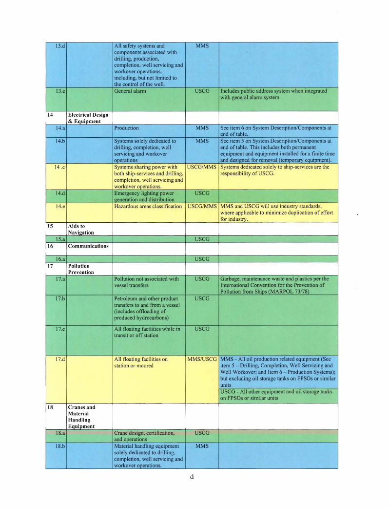
13.d All safety systems and MMS components associated with drilling, production, completion, well servicing and workover operations, including, but not limited to the control of the well.
13.e General alarm USCG Includes public address system when integrated with general alarm system
14 Electrical Design & Equipment
14.a Production MMS See item 6 on System Description/Components at end of table.
14.b Systems solely dedicated to MMS See item 5 on System Description/Components at drilling, completion, well end of table. This includes both permanent servicing and workover equipment and equipment installed for a finite time operations and designed for removal (temporal)' equipment).
14 .c _1'.)o=f' Systems sharing power with USCG/MMS Systems dedicated solely to ship-services are the both ship-services and drilling, responsibility of USCG. J completion, well servicing and I
workover operations. a
14.d Emergency lighting power USCG generation and distribution
14.e :; Hazardous areas classification USCG/MMS M Sand USCG will use industry standards, where applicable to minimize duplication of effort
o_ for industry. 15 Aids to
Navigation 15.a USCG
16 Communications
16.a USCG 17 Pollution
Prevention 17.a Pollution not associated with USCG Garbage, maintenance waste and plastics per the
vessel transfers International Convention for the Prevention of Pollution from Ships (MARPOL 73178)
17.b Petroleum and other product USCG transfers to and from a vessel (includes offloading of produced hydrocarbons)
17.c All floating facilities while in USCG transit or off station
17.d ~ All floating facilities on MMS/USCG MMS - All oil production related equipment (See station or moored item 5 - Drilling, Completion, Well Servicing and
8IJ Well Workover and Item 6 - Production Systems);
[ ~ but excluding oil storage tanks on FPSOs or similar
~ units
n USCG - All other equipment and oil storage tanks
~ on FPSOs or similar units ':;." __..____::..... _...,, ~
18 Cranes and Material Handling Equipment
18.a Crane design, certification, USCG and operations
18.b Material handling equipment MMS solely dedicated to drilling, completion well servicing and workover operations.
d
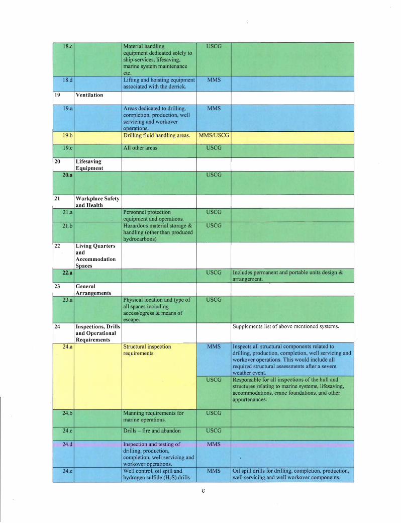
18.c Material handling USCG equipment dedicated solely to ship-services, lifesaving, marine system maintenance etc.
18.d Lifting and hoisting equipment MMS associated with the derrick.
19 Ventilation
19.a Areas dedicated to drilling, MMS completion, production, well servicing and workover operations.
19.b ~~~ Drilling fluid handling areas. MMS/USCG - -
19.c All other areas USCG
20 Lifesaving Equipment
20.a USCG
21 Workplace Safety and Health
21.a Personnel protection USCG eQuipment and operations.
21.b Hazardous material storage & USCG handling (other than produced hydrocarbons)
22 Living Quarters and Accommodation Spaces
22.a USCG Includes permanent and portable units design & arrangement. .
23 General Arrangements
23.a Physical location and type of USCG all spaces including access/egress & means of escape.
24 Inspections, Drills Supplements list of above mentioned systems. and Operational Requirements
24.a Structural inspection ~
MMS Inspects all structural components related to requirements !I drilling, production, completion, well servicing and
LJ II -
~ m workover operations. This would include all
I
~ required structural assessments after a severe
~d ] weather event.
I USCG Responsible for all inspections of the hull and
] i ~
structures relating to marine systems, lifesaving, accommodations, crane foundations, and other
~ appurtenances.
24.b Manning requirements for USCG marine operations.
24.c Drills - fire and abandon USCG
24.d Inspection and testing of MMS drilling, production, completion, well servicing and workover operations.
24.e Well control, oil spill and MMS Oil spill drills for drilling, completion, production, hydrogen sulfide (H2S) drills well servicing and well workover components.
e
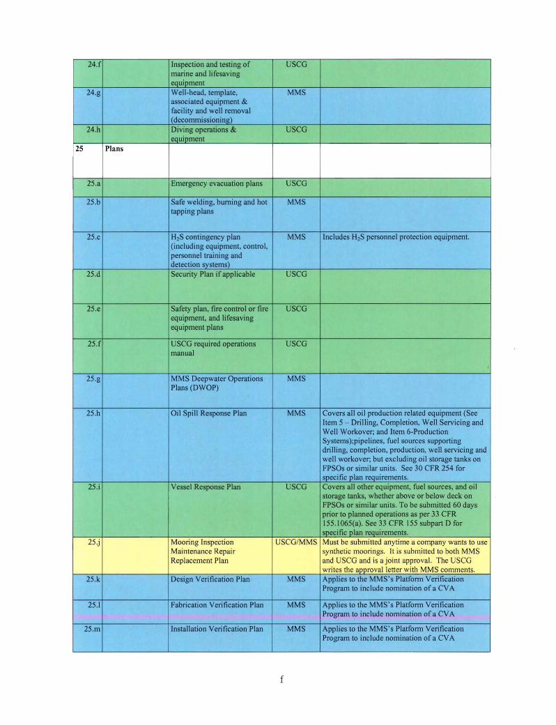
24.f Inspection and testing of USCG marine and lifesaving equipment
24.g Well-head, template, MMS associated equipment & facility and well removal (decommissioning)
24.h Diving operations & USCG equipment
25 Plans
25.a Emergency evacuation plans USCG
25.b Safe welding, burning and hot MMS tapping plans
25.c H2S contingency plan MMS Includes H2S personnel protection equipment. (including equipment, control, personnel training and detection systems)
25.d Security Plan if applicable USCG
25.e Safety plan fire control or fire USCG equipment, and lifesaving equipment plans
25.f USCG required operations USCG manual
25.g MMS Deepwater Operations MMS Plans (DWOP)
25.h Oil Spill Response Plan MMS Covers all oil production related equipment (See Item 5 - Drilling, Completion, Well Servicing and Well Workover and Item 6-Production Systems);pipelines, fuel sources supporting drilling, completion, production, well servicing and well workover; but excluding oil storage tanks on FPSOs or similar units. See 30 CFR 254 for specific plan requirements.
25.i Vessel Response Plan USCG Covers all other equipment fuel sources and oil storage tanks, whether above or below deck on FPSOs or similar units. To be submitted 60 days prior to planned operations as per 33 CFR 155.1065(a). See 33 CFR 155 subpart D for specific plan requirements.
25.j Mooring Inspection USCG/MMS Must be submitted anytime a company wants to use
I Maintenance Repair
~ II synthetic moorings. It is submitted to both MMS
I Replacement Plan and USCG and is a joint approval. The USCG - .-----, ~ writes the approval letter with MMS comments.
25.k Design Verification Plan MMS Applies to the MMS' s Platform Verification Program to include nomination of a CVA
25.l Fabrication Verification Plan MMS Applies to the MMS's Platform Verification Program to include nomination of a CVA
25.m Installation Verification Plan MMS Applies to the MMS' s Platform Verification Program to include nomination of a CVA
f

26 Turret Operations
26.a Jfu1~ Quick-disconnectable turrets and associated buoys
MMS/USCG I - -- -
26.b
I ~~-Non-readily disconnectable turrets and buoys associated with mooring and conventional risers
MMS/USCG Buoys acting as part of the mooring system
--'!
26.c Non-readily disconnectable turrets and buoys associated with conventional risers
MMS No mooring associated with buoys, only with riser system
27 Investigation Lead Responsibility
27.a Incidents involving systems the USCG has responsibility for under this MOA
USCG See MMS/USCG MOA OCS-02 for Civil Penalties; MMS/USCG MOA OCS-03 for Oil Discharge Planning, Preparedness and Response and MMS/USCG MOA OCS-5 for Incident investigation.
27.b Incidents involving systems MMS has responsibility under this MOA
MMS See MMS/USCG MOA OCS-02: Civil Penalties; MMS/USCG MOA OCS-03: Oil Discharge Planning, Preparedness and Response and MMS/USCG MOA OCS-05: Incident investigation.
28 Administer Shutdown or Resumption of Operation of a Facility
28.a MMS See Section D.10 - Abatement - MMS/USCG MOA OCS-3: Oil Discharge Planning, Preparedness and Response
29 Safety Analysis
29.a Safety analysis of industrial systems
MMS
System Descriptions/Components
Item 1. Design and Operating Overview/Plan
1.a Deepwater Operations Plans - MMS A. Conceptual Plan - General Design Basis and Philosophy
1) An overview of the development concept( s ), 2) A well location plat. 3) System control type - direct hydraulic or electro- hydraulic, and 4) Distance from each well to the host platform.
B. Deepwater Operations Plans (DWOP) 1) Description and schematic of typical wellbore, casing and completion, 2) Structural design, fabrication and installation information for each surface system, 3) Design, fabrication and installation information for the mooring systems, 4) Information on any active station keeping systems, 5) Information on the drilling and completion systems, 6) Design and fabrication information for each riser system,
g

7) Pipeline information, 8) Information on the design, fabrication and operation of any offtake systems, 9) Information on subsea wells and associated systems, 10) Flow schematics and Safety Analysis Function Evaluation of the production system, 11) A description of the surface/subsea safety system and emergency support systems, 12) A general description of the operating procedures, 13) A description of the facility installation and commissioning procedures, 14) A discussion of any new technologies proposed, and 15) A list of any alternative compliance procedures or departures proposed.
C. New Technology Document 1) A discussion of any new technologies proposed, and 2) A list of any alternative compliance procedures or departures proposed.
1.b Design Basis Document - USCG 1) Description of the facility and its configuration, 2) Design methodology, including method of analysis, design codes and regulatory,
requirements and environmental criteria and loading, 3) Design overview of primary structure and, if applicable, the tendons and mooring systems, 4) Design overview of electrical and control systems, 5) Design overview of marine and utility systems, 6) Design overview of fire-protection, lifesaving equipment and safety systems, 7) Design overview of the in-service inspection plan for the hull and tendons, including
philosophy, methodology and drawings of areas to be inspected, 8) Intact and damage stability calculations and, for TLPs, include the tendon-attached mode, 9) Description of any unique design aspects that alleviate the negative consequences of
damage stability scenarios, facilitate safe operations or enhance maintenance and inspection requirements, and
10) For converted facilities, a summary of previous service, certifications and classification status and an overview of any structural modifications proposed.
l .c Platform Verification Program - MMS A. Design Verification Plan
1) Documentation of the design including location plat, site specific geotechnical report, contract design drawings and met-ocean data,
2) Abstract of computer programs used for analysis and a 3) Summary of major design considerations and approach needed for verification.
B. Fabrication Verification Plan 1) Approved for fabrication drawings and material specifications, 2) Material traceability procedures, and 3) A summary description of structural/fabrication specifications, tolerances, quality
assurance, material quality controls/placement methods and methods/extent ofNDE testing. C. Installation Verification Plan
1) Summary description of planned marine operations, 2) Contingencies considerations, 3) Alternative course of action, and 4) An identification of areas to be inspected, specifying acceptance and rejection criteria.
Item 5. Drilling, Completion, Well Servicing and Workover Operations:
1) Drilling, production, and workover riser,
h
2) Blowout prevention equipment and control systems, 3) Drilling system and related relief valves, vent system, pressure vessels and pipeline,
pumps, water systems, and safety systems, 4) Riser and guideline tensioning systems, 5) Motion compensating systems, 6) Instruments and controls, 7) Atmospheric vessels and piping, 8) Fitness of the drilling unit, 9) Lifting and hoisting equipment associated with the derrick, 10) Cementing systems and related equipment, 11) Circulating systems and related equipment, including: pipes and pumps for drilling fluids,
workover and well servicing fluids, shale shakers, desanders, degassers and related equipment, 12) Structures including derrick and sub-structure, 13) Bulk material storage and handling systems, and 14) Other pressurized systems designed for industrial operations.
Item 6. Production Systems
1) Hydraulic and pneumatic systems, 2) Pipeline risers, 3) Production safety systems including subsurface and surface safety valves, 4) Relief valves, relief headers, vent and flare systems, 5) Production wells and wellhead, 6) Instrumentation, controls, and measurement (including oil and gas), 7) Gas compression, 8) Process system and related pumps, 9) Odorization for gas piped into enclosures, 10) Process system and related pressure vessels and piping, 11) Process system and related heat exchangers, including waste heat recovery units, 12) Chemical injection and treatment systems, and 13) Metering systems.
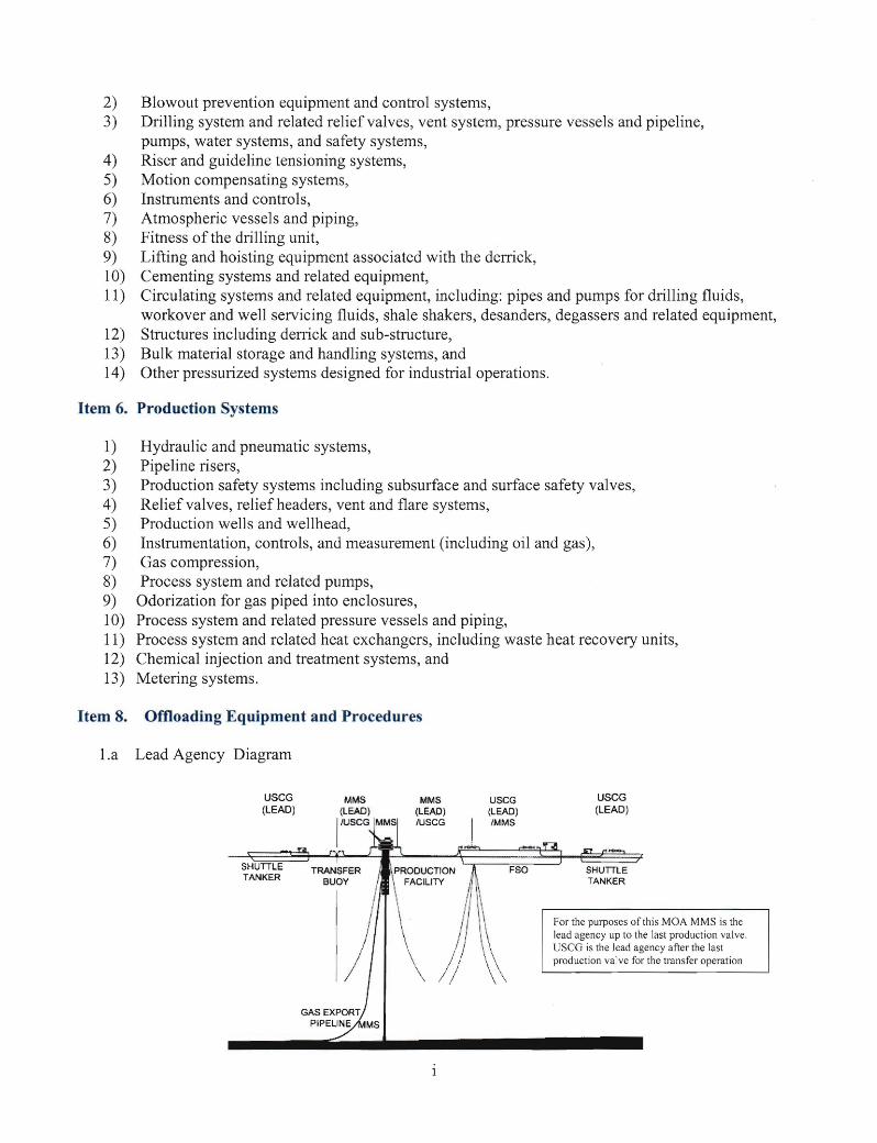
Item 8. Offloading Equipment and Procedures
1.a Lead Agency Diagram
USCG USCGMMS USCG (LEAD) (LEAD) (LEAD) (LEAD}
/USCG /MMS
SHUTILE TANKER
For the purposes of this MOA MMS is the lead agency up to the last production valve . USCG is the lead agency after the last production valve for the transfer operation

Item 12. Fire Safety Equipment and Systems
1) Deluge systems in the well bay area, 2) Firewater pumps, piping, hose reel and monitor equipment, 3) Foam extinguishing equipment, 4) Fixed gaseous extinguishing equipment (carbon dioxide (C02) and halon alternatives), 5) Fixed water mist extinguishing equipment, 6) Portable and semi-portable extinguishers, and 7) Fire and smoke detection (excludes interfaces to MMS regulated safety systems).