
Mediant 2600B - AudioCodes · 10.2 Configuring the "Route" on Skype for Business Server 2015.....59...
308
Installation & Maintenance Manual Mediant 2600B Survivable Branch Availability (SBA) for Microsoft Skype for Business Version 7.0
Transcript of Mediant 2600B - AudioCodes · 10.2 Configuring the "Route" on Skype for Business Server 2015.....59...
Installation & Maintenance Manual
Mediant 2600B Survivable Branch Availability (SBA) for Microsoft Skype for Business
Version 7.0


Version 7.0 3 Skype for Business
Installation & Maintenance Manual Contents
Contents 1 Introduction ......................................................................................................... 9
2 Verifying Package Contents ............................................................................. 13
Hardware Description .............................................................................................15
3 Front Panel ........................................................................................................ 17
3.1 OSN Server Modules ............................................................................... 18 3.1.1 OSN4 Module ......................................................................................... 18
3.1.1.1 LEDs Description .................................................................................19 3.1.1.2 Ports Description .................................................................................20
3.1.2 RJ-45 Gigabit Ethernet Cable Connector Pinouts ................................... 21 3.1.3 HDMI Connector Pinouts ........................................................................ 22 3.1.4 HDMX (Hard-Disk Drive) Module ............................................................ 23
4 E-SBC CPU Ports and LEDs ............................................................................. 25
4.1 Port Description ....................................................................................... 25 4.2 LED Description ....................................................................................... 26
5 Rear Panel .......................................................................................................... 29
Setting up the E-SBC Device ..................................................................................31
6 Connecting to Power ........................................................................................ 33
7 Initial Access to the E-SBC Device .................................................................. 35
8 Changing OAMP Interface ................................................................................ 37
Preparing SBA at the DataCenter ...........................................................................39
9 Adding the SBA Device to the Active Directory ............................................. 41
10 Defining Branch Office Topology-Skype for Business Server 2015 ............. 45
10.1 Defining the SBA Branch Office and Associated E-SBC Device ......... 45 10.2 Configuring the "Route" on Skype for Business Server 2015 ............. 59
Setting up the SBA with Management Interface ...................................................69
Installation & Maintenance Manual 4 Document #: LTRT-39482
Mediant 2600B SBA
11 Connecting to the SBA Management Interface .............................................. 71
11.1 Connecting to SBA Using the Internal NIC ............................................ 71 11.2 Connecting to the SBA Using the External NIC .................................... 76
12 Installing and Configuring the SBA ................................................................. 79
12.1 Step 1: Define IP Settings ....................................................................... 81 12.2 Step 2: Change Computer Name ............................................................ 84 12.3 Step 3: Change Admin Password .......................................................... 88 12.4 Step 4: Set Date and Time....................................................................... 90 12.5 Step 5: Join to a Domain ......................................................................... 93 12.6 Step 6: Device Preparation ..................................................................... 97 12.7 Step 7: Cs Database Installation .......................................................... 100 12.8 Step 8: Backup ....................................................................................... 102 12.9 Step 9: Enable Replication.................................................................... 104 12.10Step 10: Activate Lync .......................................................................... 106 12.11Step 11: Lync Certificate ...................................................................... 108 12.12Step 12: Start Lync Services ................................................................ 115 12.13Step 13: Configure E-SBC Test Calls .................................................. 117 12.14Step 14: Test Lync Calls ....................................................................... 120
12.14.1 Test Prerequisites ................................................................................ 120 12.14.2 Running the Skype for Business Call Test ............................................ 121
12.15Step 15: Apply Security ........................................................................ 123 12.15.1 Apply No Policy .................................................................................... 123 12.15.2 Apply Default Security Template .......................................................... 125 12.15.3 Apply User-Defined Security Template ................................................. 128
12.16Step 16: (Optional) Remote Control..................................................... 131 12.17Step 17 (Optional) SNMP Setup ........................................................... 132 12.18Step 18: Completing SBA Setup .......................................................... 139 12.19Monitoring and Maintenance Actions .................................................. 141
12.19.1 Viewing General SBA Status in the Home Page ................................... 141 12.19.2 Starting and Stopping SBA Services .................................................... 142 12.19.3 Viewing Logged Events ........................................................................ 143 12.19.4 Logging Out .......................................................................................... 144
Configuring the E-SBC Device .............................................................................145
13 Configuring AudioCodes E-SBC .................................................................... 147
13.1 Step 1: IP Network Interfaces Configuration ....................................... 148 13.1.1 Step 1a: Configure VLANs ................................................................... 148 13.1.2 Step 1b: Configure Network Interfaces ................................................. 149

Version 7.0 5 Skype for Business
Installation & Maintenance Manual Contents
13.2 Step 2: Enable the SBC Application .................................................... 151 13.3 Step 3: Configure Media Realms .......................................................... 151 13.4 Step 4: Configure SIP Signaling Interfaces ......................................... 154 13.5 Step 5: Configure Proxy Sets ............................................................... 156 13.6 Step 6: Configure IP Profiles ................................................................ 160 13.7 Step 7: Configure IP Groups ................................................................. 167 13.8 Step 8: Configure Coders ..................................................................... 168 13.9 Step 9: SIP TLS Connection Configuration ......................................... 171
13.9.1 Step 9a: Configure the NTP Server Address ........................................ 171 13.9.2 Step 9b: Configure the TLS version 1.0 ................................................ 172 13.9.3 Step 9c: Configure a Certificate ............................................................ 173
13.10Step 10: Configure SRTP ...................................................................... 179 13.11Step 11: Configure Maximum IP Media Channels .............................. 181 13.12Step 12: Configure IP-to-IP Call Routing Rules .................................. 182 13.13Step 13: Configure IP-to-IP Manipulation Rules ................................. 189 13.14Step 14: Configure Message Manipulation Rules............................... 192 13.15Step 15: Configure Registration Accounts ......................................... 198 13.16Step 16: Miscellaneous Configuration ................................................ 199
13.16.1 Step 16a: Configure Call Forking Mode ................................................ 199 13.16.2 Step 16b: Configure SBC Alternative Routing Reasons........................ 200
13.17Step 17: Reset the E-SBC ..................................................................... 201
Upgrading SBA Components ...............................................................................203
14 Upgrading MSFT and CU System Components ........................................... 205
15 Upgrading the Management Interface ........................................................... 209
16 Upgrading using the SBA ProConnect .......................................................... 212
Upgrade and Recovery .........................................................................................213
17 Upgrade and Recovery - Introduction ........................................................... 215
18 Upgrade and Recovery - Prerequisites ......................................................... 217
19 Customizing SBA Upgrade and Recovery .................................................... 219
19.1 Defining Manual or Automatic Start ..................................................... 219 19.2 Running the Process Immediately or Upon User Confirmation ........ 220 19.3 Checking Disk before Image Burn ....................................................... 220 19.4 Creating Disk Partitions ........................................................................ 220 19.5 Enabling SBA Image Burn on Primary Partition ................................. 221 19.6 Defining Exit Operation upon Process Completion ........................... 221 19.7 Defining Network Parameters ............................................................... 222 19.8 Defining the SBA Image File Name ...................................................... 223 19.9 Defining the SBA Image File Source .................................................... 223
19.9.1 Defining the FTP .................................................................................. 224

Installation & Maintenance Manual 6 Document #: LTRT-39482
Mediant 2600B SBA
19.9.2 Defining the Local Network ................................................................... 224 19.9.3 Defining the Disk On Key ..................................................................... 224 19.9.4 Defining the Recovery Partition ............................................................ 225
19.10Defining the MAC Address Prefix ........................................................ 225
20 SBA Upgrade and Recovery ........................................................................... 227
20.1 Starting Process without Monitoring ................................................... 227 20.2 Starting Process with Online Monitoring using EMS ......................... 229 20.3 Starting Process with Online Monitoring using Monitor .................... 237 20.4 Acquiring an IP Address ....................................................................... 240
Appendix ................................................................................................................245
A SBA Security Default Template ...................................................................... 247
A.1 Server Roles........................................................................................... 247 A.2 Client Features ....................................................................................... 249 A.3 Administration and Other Options ....................................................... 250 A.4 Services .................................................................................................. 251 A.5 Windows Update Policy ........................................................................ 272 A.6 Firewall Rules ........................................................................................ 273
A.6.1 Default SBA Internal Firewall Rules ...................................................... 273 A.6.2 SBA Network Firewall Settings ............................................................. 294
B Running Anti-Virus Software ......................................................................... 297
C Configuring RAID ............................................................................................ 299
C.1 Prerequisites .......................................................................................... 299 C.2 Slot Assignments for OSN Hard Drives ............................................... 299 C.3 Configuring RAID 1 ............................................................................... 300
Version 7.0 7 Skype for Business
Installation & Maintenance Manual Notices
Notice
This manual describes the installation and maintenance of AudioCodes Mediant 2600B Survivable Branch Appliance (SBA).
Information contained in this document is believed to be accurate and reliable at the time of printing. However, due to ongoing product improvements and revisions, AudioCodes cannot guarantee accuracy of printed material after the Date Published nor can it accept responsibility for errors or omissions. Before consulting this document, check the corresponding Release Notes regarding feature preconditions and/or specific support in this release. In cases where there are discrepancies between this document and the Release Notes, the information in the Release Notes supersedes that in this document. Updates to this document and other documents as well as software files can be downloaded by registered customers at http://www.audiocodes.com/downloads.
© Copyright 2016 AudioCodes Ltd. All rights reserved.
This document is subject to change without notice.
Date Published:May-02-2016
Trademarks
AudioCodes, AC, HD VoIP, HD VoIP Sounds Better, IPmedia, Mediant, MediaPack, What’s Inside Matters, OSN, SmartTAP, VMAS, VoIPerfect, VoIPerfectHD, Your Gateway To VoIP, 3GX, VocaNOM and CloudBond 365 are trademarks or registered trademarks of AudioCodes Limited All other products or trademarks are property of their respective owners. Product specifications are subject to change without notice.
WEEE EU Directive
Pursuant to the WEEE EU Directive, electronic and electrical waste must not be disposed of with unsorted waste. Please contact your local recycling authority for disposal of this product.
Customer Support
Customer technical support and services are provided by AudioCodes or by an authorized AudioCodes Service Partner. For more information on how to buy technical support for AudioCodes products and for contact information, please visit our Web site at www.audiocodes.com/support.
Abbreviations and Terminology
Each abbreviation, unless widely used, is spelled out in full when first used. Throughout this manual and unless otherwise specified, the term device refers to the Mediant 2600B SBA.

Installation & Maintenance Manual 8 Document #: LTRT-39482
Mediant 2600B SBA
Related Documentation
Manual Name
Mediant 2600B SBA Quick Guide
Mediant 2600B SBA Hardware Installation Manual
Notes and Warnings
Warning: The device is an INDOOR unit and thus, must be installed ONLY indoors. In addition, Ethernet port interface cabling must be routed only indoors and must not exit the building.
Avertissement: L’appareil est une unité d’INTERIEUR et doit donc obligatoirement être installé en intérieur. En outre, le câblage de l’interface du port Ethernet doit être acheminé uniquement en intérieur et ne doit pas sortir du bâtiment.
Warning: Installation of this device must be in a weather protected location of maximum ambient temperature of 40°C.
Avertissement: L’installation de cet appareil doit avoir lieu dans un local protégé des intempéries de température ambiante maximale de 40°C.
Warning: This device must be installed only in a restricted access location.
Avertissement: L’entretien de maintenance de cet appareil doit être effectué uniquement par un personnel de service qualifié dans des locaux à accès limité et l’appareil étant branché à une prise mise à la masse.
Warning: Service of the device must be made only by qualified service personnel.
Warning: The device must be connected only to a grounded AC mains power socket.
Version 7.0 9 Skype for Business
Installation & Maintenance Manual 1. Introduction
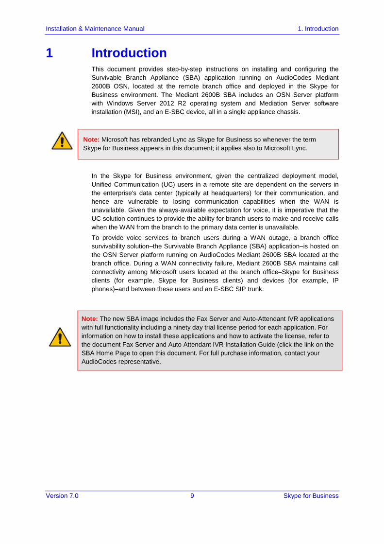
1 Introduction This document provides step-by-step instructions on installing and configuring the Survivable Branch Appliance (SBA) application running on AudioCodes Mediant 2600B OSN, located at the remote branch office and deployed in the Skype for Business environment. The Mediant 2600B SBA includes an OSN Server platform with Windows Server 2012 R2 operating system and Mediation Server software installation (MSI), and an E-SBC device, all in a single appliance chassis.
Note: Microsoft has rebranded Lync as Skype for Business so whenever the term Skype for Business appears in this document; it applies also to Microsoft Lync.
In the Skype for Business environment, given the centralized deployment model, Unified Communication (UC) users in a remote site are dependent on the servers in the enterprise's data center (typically at headquarters) for their communication, and hence are vulnerable to losing communication capabilities when the WAN is unavailable. Given the always-available expectation for voice, it is imperative that the UC solution continues to provide the ability for branch users to make and receive calls when the WAN from the branch to the primary data center is unavailable. To provide voice services to branch users during a WAN outage, a branch office survivability solution–the Survivable Branch Appliance (SBA) application–is hosted on the OSN Server platform running on AudioCodes Mediant 2600B SBA located at the branch office. During a WAN connectivity failure, Mediant 2600B SBA maintains call connectivity among Microsoft users located at the branch office–Skype for Business clients (for example, Skype for Business clients) and devices (for example, IP phones)–and between these users and an E-SBC SIP trunk.
Note: The new SBA image includes the Fax Server and Auto-Attendant IVR applications with full functionality including a ninety day trial license period for each application. For information on how to install these applications and how to activate the license, refer to the document Fax Server and Auto Attendant IVR Installation Guide (click the link on the SBA Home Page to open this document. For full purchase information, contact your AudioCodes representative.

Version 7.0 10 Document #: LTRT-39482
Mediant 2600B SBA
Figure 1-1: SBA Home Page (Additional AudioCodes Applications Link) New SBA Image
Figure 1-2: SBA Home Page (Additional AudioCodes Applications Link) SBA Upgrade

Version 7.0 11 Skype for Business
Installation & Maintenance Manual 1. Introduction
The figure below illustrates typical SBA branch office deployment scenarios.
Figure 1-3: Typical Branch Office Deployments
Version 7.0 12 Document #: LTRT-39482
Mediant 2600B SBA
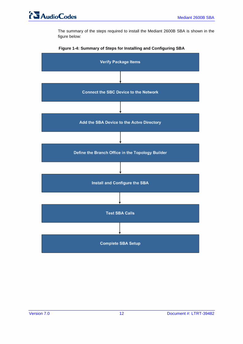
The summary of the steps required to install the Mediant 2600B SBA is shown in the figure below:
Figure 1-4: Summary of Steps for Installing and Configuring SBA
Version 7.0 13 Skype for Business
Installation & Maintenance Manual 2. Verifying Package Contents
2 Verifying Package Contents Ensure that your Mediant 2600B SBA package is shipped with the following items:
Two adjustable rear-rack mounting bracket kits (60 cm and 80 cm) for 19-inch rack mounting
Four anti-slide bumpers for desktop mounting
Serial interface cable adaptor
Cable mini HDMI to HDMI 1.5m for monitor connections
Cable micro USB to USB 1.5m for serial connections
USB dongle for SBA software upgrade and recovery procedure
Microsoft Windows 2012 R2 license document (envelope)
Two AC power cables
Check, retain and process any documents. If any items are missing or damaged, please contact your AudioCodes sales representative.

Version 7.0 14 Document #: LTRT-39482
Mediant 2600B SBA
This page is intentionally left blank.

Part I Hardware Description
This part provides a hardware description overview of the Mediant 2600B SBA device. The Mediant 2600B SBA is resident on the Mediant 2600B SBA Gateway and E-SBC chassis. The chassis' panels are described as follows:
Front Panel - see Section 'Front Panel' on page 29
Rear Panel - see Section 'Rear Panel' on page 29
The AudioCodes SBA is installed on the HDMX disk module and runs on the OSN processor module. These modules are described in Section 'OSN Server Modules' on page 18.


Version 7.0 17 Skype for Business
Installation & Maintenance Manual 3. Front Panel
3 Front Panel The device's front panel is shown in the figure below and described in the subsequent table.
Figure 3-1: Front Panel
Note: The figure above provides only an example of the Mediant 2600B. The modules housed in your Mediant 2600B may be slightly different, depending on the ordered hardware configuration (e.g., Media Processing Module / MPM and OSN server modules).
Table 3-1: Front-Panel Description
Item # Component Description
1 Fan Tray module #1. For more information on the module, refer to the Mediant 2600B Hardware Manual.
2 (Slots 1-2) Unused slots shown with two blank slot covers. The slots can house an optional, Media Processing Module (MPM). The MPM module occupies two slots. Note: The MPM is a customer-ordered item.
3 (Slots 3-4) E-SBC CPU AMC module (hereafter referred to as E-SBC). The E-SBC module occupies two slots. The module provides the central processing unit (CPU), serial interface, and Ethernet port interface functionalities. For more information, refer to the Mediant 2600B Hardware Manual.
4 (Slots 5-6) OSN server modules (OSN4 and HDMX). The OSN4 module is housed in Slot 5 and the HDMX module in Slot 6.
5 (Slots 7-8) Unused slots shown covered with two blank slot covers. The slots can house one of the following optional modules: MPM module, on condition that MPM modules are also housed in the slots described
in Item #2 and Item #4 (if not occupied by OSN modules). The MPM module occupies two slots.
Secondary HDMX module for the OSN server (see Item #4). The module is installed in Slot 7. This module is installed when configuring the SBA in a RAID configuration. For more information see, 'Part VI: Appendices' on page 246.

Version 7.0 18 Document #: LTRT-39482
Mediant 2600B SBA
Item # Component Description
Note: The MPM is a customer-ordered item.
6 Fan Tray module #2 with a schematic displayed on its front panel showing the chassis' slot numbers. For more information on the module, refer to the Mediant 2600B Hardware Manual.
3.1 OSN Server Modules The OSN4 server modules are customer-ordered items. The OSN server consists of two modules:
OSN4 - central processing unit (CPU), RAM, and port interfaces (see Section 3.1.1).
HDMX - hard-disk drive (HDD or SSD) providing storage capacity (see Section 3.1.4).
The specifications of the OSN server are listed in the following table:
Table 3-2: OSN4 Server Specifications
CPU Memory Storage Interfaces
Intel® Core™ i7 3rd Generation Dual Core 2.5 GHz
8 GB DDR3 with ECC
Up to 2 hard drives: HDD or SSD
Two external Gigabit Ethernet
USB 2.0 RS-232 COM HDMI Graphic
3.1.1 OSN4 Module This section describes the ports and LEDs on the OSN4 module.
Warning: The OSN4 module contains a non-rechargeable Lithium-ion (LI-ion) battery. If required, replace the Lithium battery only with the following battery type:
• Manufacturer: Hitachi Maxell Energy Ltd. • Battery Type: CR2032M1SB-LF; Li/MnO2, 3V 210mAh

Version 7.0 19 Skype for Business
Installation & Maintenance Manual 3. Front Panel
3.1.1.1 LEDs Description The OSN4 module LEDs are shown in the figure below and described in the subsequent table.
Figure 3-2: OSN4 Module LEDs
Table 3-3: OSN4 Module LEDs Description
Item Color State Description
1 Green Flashing Firmware (BIOS) application active, payload (x86) in sleep.
Solid Firmware (BIOS) application active, payload (x86) active.
2 Red On Out-of-service indicator due to hardware failure.
- Off Normal operation.
3 Green Solid Valid Ethernet link (cable connection) established.
Flashing Activity in the link.
- Off The LED goes temporarily off if network packets are sent or received. When this LED remains off, a valid link has not been established due to a missing or a faulty cable connection.
4 Orange On 2600Base-TX connection.
Green On 100Base-T connection.
- Off 10Base-T connection if LED #3 is active.
5 Blue Flashing Module undergoing shutdown sequence when handle is pulled out to first extraction position, or module had been inserted and handle is still in first extraction position
On Module shutdown sequence complete and the module can be extracted from the chassis slot.
Off Module correctly inserted in chassis slot.

Version 7.0 20 Document #: LTRT-39482
Mediant 2600B SBA
3.1.1.2 Ports Description The OSN4 module is shown below and described in the subsequent table.
Figure 3-3: OSN4 Module Ports
Table 3-4: OSN4 Module Port Description
Item # Label Description
1
USB 2.0 port.
2
2 RJ-45 ports for Gigabit Ethernet. The interface provides automatic detection and switching between 10Base-T, 100Base-TX and 2600Base-T data transmission (Auto-Negotiation). Auto-wire switching for crossed cables is also supported (Auto-MDI/X).
3 HDMI Micro HDMI port Type-D male connector (for connecting to a graphic display monitor.
4 Console (serial) port (micro-USB) for serial interface (COM1).

Version 7.0 21 Skype for Business
Installation & Maintenance Manual 3. Front Panel
Item # Label Description
5 Reset pinhole button. To warm reset the operating system of the OSN server (i.e., power
remains on): Press and then immediately release the button (less than five seconds). The LED indications are as follows (see LEDs description for LED locations):
-Upon reset: -LED #1: On (solid green) -LED #2: On (solid red) -End of reset: LED #1 remains on (solid green); all other LEDs off. To cold (hard) reset the OSN server (i.e., powers off and then powers
on): Press the button for longer than five seconds and then release. The LED indications are as follows (see LEDs description for LED locations):
-Upon reset: -LED #1: On (solid green) -LED #2: On (solid red) -LED #5: On (solid blue) -End of reset: LED #1 remains on (solid green); all other LEDs off.
3.1.2 RJ-45 Gigabit Ethernet Cable Connector Pinouts The RJ-45 connector pinouts for the Gigabit Ethernet interface are listed in the table below.
Table 3-5: RJ-45 Connector Pinouts for Gigabit Ethernet Interface
Pin 100Base-Tx 2600Base-T
I/O Signal Signal Function
1 O Tx+ I/O BI_DA+
2 0 Tx- I/O BI_DA-
3 I Rx+ I/O BI_DB+
4 I/O BI_DC+
5 I/O BI_DC-
6 I Rx- I/O BI_DB-
7 I/O BI_DD+
8 I/O BI_DD-

Version 7.0 22 Document #: LTRT-39482
Mediant 2600B SBA
3.1.3 HDMI Connector Pinouts The HDMI connector pinouts for the HDMI interface are described in the table below.
Table 3-6: HDMI Type-D Connector Pinouts
Pin Signal
3 TMDS Data2+
4 TMDS Data2 Shield
5 TMDS Data2-
6 TMDS Data1+
7 TMDS Data1 Shield
8 TMDS Data1-
9 TMDS Data0+
10 TMDS Data0 Shield
11 TMDS Data0-
12 TMDS Clock+
13 TMDS Clock Shield
14 TMDS Clock-
15 CEC
2 Utility/HEAC+
17 SCL
18 SDA
16 DDC/CEC/HEAC Ground
19 +5 V Power
1 Hot Plug Detect/HEAC

Version 7.0 23 Skype for Business
Installation & Maintenance Manual 3. Front Panel
3.1.4 HDMX (Hard-Disk Drive) Module The HDMX module provides the hard-disk drive functionality for the OSN platform. This module is housed in Slot #1 on the Mediant 2600B SBA rear panel.
Note:
• For additional storage capacity per HDMX module, contact your AudioCodes representative.
• The OSN platform can optionally be ordered with dual hard-disk drives (i.e., two HDMX modules).
The HDMX module is available as either an HDD drive or as an SSD drive. The HDMX module is shown below and described in the subsequent table.
Figure 3-4: HDMX Module LEDs
Table 3-7: HDMX Module LED Description
Item # Label Color State Description
1
Green On Power received by module.
- Off No power received by module.
2 Blue On Module can be extracted from chassis slot once dismounted from the OSN operating system.
Off Module correctly inserted in chassis slot
1
Red On Hard disk drive in use (active).
- Off Hard disk drive not in use.

Version 7.0 24 Document #: LTRT-39482
Mediant 2600B SBA
This page is intentionally left blank.
Version 7.0 25 Skype for Business
Installation & Maintenance Manual 4. E-SBC CPU Ports and LEDs
4 E-SBC CPU Ports and LEDs This section describes the E-SBC CPU Ports and LEDs of the Mediant 2600B device.
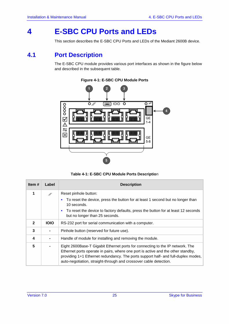
4.1 Port Description The E-SBC CPU module provides various port interfaces as shown in the figure below and described in the subsequent table.
Figure 4-1: E-SBC CPU Module Ports
Table 4-1: E-SBC CPU Module Ports Description
Item # Label Description
1 Reset pinhole button: To reset the device, press the button for at least 1 second but no longer than
10 seconds. To reset the device to factory defaults, press the button for at least 12 seconds
but no longer than 25 seconds.
2 IOIO RS-232 port for serial communication with a computer.
3 - Pinhole button (reserved for future use).
4 - Handle of module for installing and removing the module.
5 - Eight 2600Base-T Gigabit Ethernet ports for connecting to the IP network. The Ethernet ports operate in pairs, where one port is active and the other standby, providing 1+1 Ethernet redundancy. The ports support half- and full-duplex modes, auto-negotiation, straight-through and crossover cable detection.
Version 7.0 26 Document #: LTRT-39482
Mediant 2600B SBA
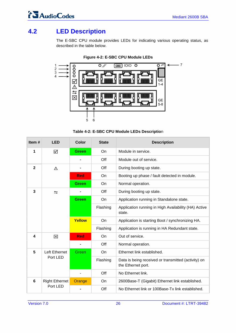
4.2 LED Description The E-SBC CPU module provides LEDs for indicating various operating status, as described in the table below.
Figure 4-2: E-SBC CPU Module LEDs
Table 4-2: E-SBC CPU Module LEDs Description
Item # LED Color State Description
1 Green On Module in service.
- Off Module out of service.
2 - Off During booting up state.
Red On Booting up phase / fault detected in module.
Green On Normal operation.
3 - Off During booting up state.
Green On Application running in Standalone state.
Flashing Application running in High Availability (HA) Active state.
Yellow On Application is starting Boot / synchronizing HA.
Flashing Application is running in HA Redundant state.
4 Red On Out of service.
- Off Normal operation.
5 Left Ethernet Port LED
Green On Ethernet link established.
Flashing Data is being received or transmitted (activity) on the Ethernet port.
- Off No Ethernet link.
6 Right Ethernet Port LED
Orange On 2600Base-T (Gigabit) Ethernet link established.
- Off No Ethernet link or 100Base-Tx link established.

Version 7.0 27 Skype for Business
Installation & Maintenance Manual 4. E-SBC CPU Ports and LEDs
Item # LED Color State Description
7 Blue On Blue hot-swap LED indicating that the AMC module can be fully removed or inserted. Note: Do not remove the module before this LED turns blue.
- Off Module insertion process is complete.

Version 7.0 28 Document #: LTRT-39482
Mediant 2600B SBA
This page is intentionally left blank.

Version 7.0 29 Skype for Business
Installation & Maintenance Manual 5. Rear Panel
5 Rear Panel The chassis rear panel is displayed in the figure below and described in the subsequent table.
Figure 5-1: Rear Panel
Table 5-1: Rear-Panel Description
Item # Label Description
1 Earthing Protective earthing (grounding) screw.
2 PS 1 Power Supply module No. 1. For more information, see ??
3 PS 2 Power Supply module No. 2. For more information, see ??
4 ESD Electrostatic Discharge (ESD) lug.
5 PWR Power status LED for indicating the status of the Power Supply module. For more information, see ???
6 - Extraction-handle for removing the Power Supply module.
7 100-240V~7A 50-60Hz AC power supply inlet (100-240V~7A, 50-60 Hz) of Power Supply module.

Version 7.0 30 Document #: LTRT-39482
Mediant 2600B SBA
This page is intentionally left blank.

Part II Setting up the E-SBC Device


Version 7.0 33 Skype for Business
Installation & Maintenance Manual 6. Connecting to Power
6 Connecting to Power The procedure below describes how to connect the device to the power supply.
Table 6-1: Power Specifications
Item Description
Power Supply Two hot swappable, power supply modules for power load sharing and AC power redundancy in case of failure of one of the modules.
Input Ratings Single universal power supply 100-240 VAC, 50-60 Hz, 7A max.
Output Ratings Output 1: 12 VDC / 40A max Output 2: 12 VDC / 9A Output 3: 3.3 VDC / 2A
Connection to Electrical Outlet AC power supply inlet.
Warnings:
• Both Power Supply modules (1 and 2) must be connected. Ensure that you connect each one to a different AC power supply source. Two Power Supplies provide 1+1 power load-sharing and redundancy. The AC power sockets are located on the device's rear panel.
• The two AC power sources must have the same ground potential. • The device must be connected (by service personnel) to a socket-outlet with a protective
earthing connection. • Use only a certified 3-conductor power cord, utilizing 18 AWG or 1 mm2 wires, and no
longer than 4.5 meters (14.8 ft). • If a failure occurs in any one of the Power Supply modules, replace the module
immediately.

Version 7.0 34 Document #: LTRT-39482
Mediant 2600B SBA
To connect the device to the power supply:
1. Connect the AC power cord (supplied) to one of the power sockets located on the rear panel.
Figure 6-1: Connecting to Power
2. Connect the other end of the power cord to a standard AC electrical outlet (100-240V~50-60 Hz).
3. Repeat steps 1 through 2 for connecting the second Power Supply module, but using the power socket associated with the second Power Supply module and connecting this to a different supply circuit.
4. Turn on the power at the power source (if required). 5. Check that the POWER LED on each Power Supply module (front panel) is lit
green, indicating that the device is receiving power.

Version 7.0 35 Skype for Business
Installation & Maintenance Manual 7. Initial Access to the E-SBC Device
7 Initial Access to the E-SBC Device Before you can configure the E-SBC device, you need to access its Web interface using the default VoIP / Management LAN IP address, as described in below. The cabling specifications and procedure for connecting the device to the LAN is as follows:
Cable: Straight-through, Category (Cat) 5, 5e or 6 cable
Connector: Standard RJ-45
Connector Pinouts:
Table 7-1: RJ-45 Connector Pinouts
Pin Name Description
1 BI_DA+ Bi-directional pair A+
2 BI_DA- Bi-directional pair A-
3 BI_DB+ Bi-directional pair B+
4 BI_DC+ Bi-directional pair C+
5 BI_DC- Bi-directional pair C-
6 BI_DB- Bi-directional pair B-
7 BI_DD+ Bi-directional pair D+
8 BI_DD- Bi-directional pair D-
The following procedure describes how to change the IP address of the OAMP on the VoIP-LAN interface, using the Web-based management tool (Web interface). The default IP address is used to initially access the device.
To configure the VoIP-LAN IP Address for OAMP, using the Web interface:
1. Connect the first Ethernet port group (top-left ports 1 and 2) located on the front panel directly to the LAN network interface of your computer, using a straight-through Ethernet cable.
Figure 7-1: Connecting to the LAN Interface
Version 7.0 36 Document #: LTRT-39482
Mediant 2600B SBA
Note: For initial network connectivity to the device, use ports GE 1 or GE 2 to connect to the LAN. These ports (or this Ethernet Group) are assigned to the OAMP interface (192.168.0.2) by default. For port names as well as Ethernet port groups (for 1+1 redundancy), see Chapter 8.
2. Change the IP address and subnet mask of your computer to correspond with the default OAMP IP address and subnet mask of the device.
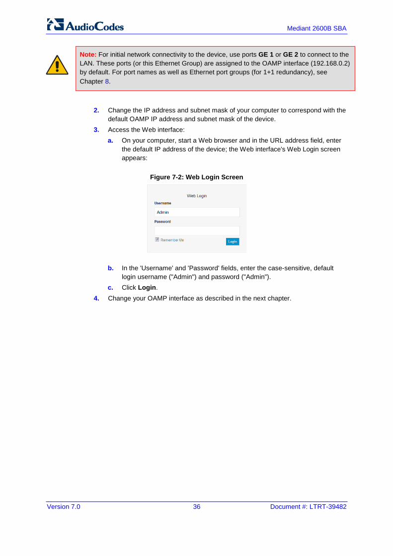
3. Access the Web interface: a. On your computer, start a Web browser and in the URL address field, enter
the default IP address of the device; the Web interface's Web Login screen appears:
Figure 7-2: Web Login Screen
b. In the 'Username' and 'Password' fields, enter the case-sensitive, default login username ("Admin") and password ("Admin").
c. Click Login. 4. Change your OAMP interface as described in the next chapter.

Version 7.0 37 Skype for Business
Installation & Maintenance Manual 8. Changing OAMP Interface
8 Changing OAMP Interface Once you have accessed your device using the default IP address, you can change your management interface (OAMP) to suit your network environment. Maintain the same cable connection that you used when you initially accessed the device.
To change OAMP IP address:
1. Assign the physical Ethernet ports that you wish to user for OAMP to an Ethernet Group in the Ethernet Groups table (Configuration tab > VoIP menu > Network > Ethernet Groups Table). The table uses special string names to represent the physical ports (refer to the figure below):
Figure 8-1: Ethernet Group String Names
2. Configure settings (for example, port speed) for your Ethernet ports in the Ethernet Group in the Physical Ports Table (Configuration tab > VoIP menu > Network > Physical Ports Table).
3. Configure the VLAN ID (Ethernet Device) for the Ethernet Group in the Ethernet Device Table (Configuration tab > VoIP menu > Network > Ethernet Device Table).

Version 7.0 38 Document #: LTRT-39482
Mediant 2600B SBA
4. Change the IP address of the OAMP interface and assign the Ethernet Device (Ethernet Group) in the IP Interfaces Table (Configuration tab > VoIP menu > Network > IP Interfaces Table):
8-2: Interface Table
a. Select the row corresponding to the OAMP + Media + Control application type, and then click Edit.
b. Change the IP address to correspond with your network IP addressing scheme, for example: ♦ IP Address: 10.8.6.86 ♦ Prefix Length: 24 (for 255.255.255.0) ♦ Gateway: 10.8.6.85 ♦ Underlying Device: Select the Ethernet Device (VLAN and associated
Ethernet Group) that you configured in Step 3. c. Click Add.
5. Save your settings by resetting the device with a flash burn. 6. Disconnect the PC from the device and re-cable the device to your network. You
can now access the management interface using the new OAMP IP address.
Note: For more information on the above procedures, refer to the Mediant 2600 E-SBC User's Manual.

Part III Preparing SBA at the DataCenter
Prior to installing and configuring the SBA at the branch office (see 'Installing and Configuring the SBA' on page 79) you must perform the following actions at the datacenter (typically, located at headquarters):
Add the SBA Device to the Active Directory (AD). See Chapter 'Adding the SBA Device to the Active Directory' on page 41
Create a user account on the AD belonging to the RTCUniversalSBATechnicians group. This user performs the SBA deployment (Domain Admin account can also perform SBA deployment, by default). See 'Adding the SBA Device to the Active Directory' on page 41
Add (publish) the SBA Device to your topology. See Chapter 'Defining the Branch Office Topology using Topology Builder' on page 45
Once these actions have been performed, you can join the SBA in the branch site to the Active Directory domain and activate the Lync services.


Version 7.0 41 Skype for Business
Installation & Maintenance Manual 9. Adding the SBA Device to the Active Directory
9 Adding the SBA Device to the Active Directory The procedure below describes how to add the SBA device to the AD.
To add the SBA device to the Active Directory:
1. Add the planned Survivable Branch Appliance device name to the Active Directory Domain Services: a. Start the Active Directory Users and Computers program (Start > Active
Directory Users and Computers). b. Add the Survivable Branch Appliance device name to the domain computers
(right-click Computers, choose New, and then click Computer).
Figure 9-1: New Object Computer Dialog Box
c. Click Change to add a user or group that can join this specific SBA server to the domain. If you are working with the Domain Administrator, do not change the "Domain Admin" group. If you are working with another user, specify the name of a user or group that is allowed to join this computer to the domain:

Version 7.0 42 Document #: LTRT-39482
Mediant 2600B SBA
Figure 9-2: Select User or Group to Change
d. In the "Enter the object name" text box, enter RTCUniversalSBATechnicians and click Check Names.
e. Click OK. f. Start the ADSI Edit program (Start > Administrative Tools > ADSI Edit). g. Right-click the Survivable Branch Appliance computer name that you just
created, and then choose Properties.
Figure 9-3: ADSI Edit
h. In the Attributes Editor list, select servicePrincipalName.

Version 7.0 43 Skype for Business
Installation & Maintenance Manual 9. Adding the SBA Device to the Active Directory
Figure 9-4: Attribute Editor
i. Click Edit and enter the value "HOST/<SBA FQDN>", where SBA FQDN is the FQDN of your Survivable Branch Appliance (e.g., HOST/SBA15.iSFB15.local).
2. In the Active Directory Users and Computers Users folder, add the new SBA computer to the RTCUniversalReadOnlyAdmins attribute.
3. In Active Directory Users and Computers, create a user account belonging to the RTCUniversalSBATechnicians group. This user performs the Survivable Branch Appliance deployment.

Version 7.0 44 Document #: LTRT-39482
Mediant 2600B SBA
This page is intentionally left blank.

Version 7.0 45 Skype for Business
Installation & Maintenance Manual 10. Defining Branch Office Topology-Skype for Business Server 2015
10 Defining Branch Office Topology-Skype for Business Server 2015 This section describes how to add the Survivable Branch Appliance to your topology, using Skype for Business Topology Builder. This configuration includes the following main steps:
Defining the branch office SBA and its associated E-SBC device – see below.
Configure a "Route" on the Skype for Business Server 2015 and associate it with the E-SBC device (see Section 10.2 on page 59).
Note: References in this section to PSTN Gateway in the Skype for Business Topology Builder and in these procedures refers to the AudioCodes E-SBC device.
10.1 Defining the SBA Branch Office and Associated E-SBC Device The procedure below describes how to define the branch office with the SBA and its associated E-SBC device.
To define the branch office and associate it with Mediation Server:
1. On the server where the Topology Builder is installed, start the Skype for Business Server 2015 Topology Builder (Windows Start menu > search for Skype for Business Server Topology Builder), as shown below:
Figure 10-1: Starting the Skype for Business Server Topology Builder

Version 7.0 46 Document #: LTRT-39482
Mediant 2600B SBA
The following is displayed:
Figure 10-2: Topology Builder Dialog Box
2. Select the Download Topology from existing deployment option, and then click OK; you are prompted to save the downloaded Topology:
Figure 10-3: Save Topology As
3. Enter a name for the Topology file, and then click Save. This step enables you to roll back from any changes you make during the installation.
Version 7.0 47 Skype for Business
Installation & Maintenance Manual 10. Defining Branch Office Topology-Skype for Business Server 2015
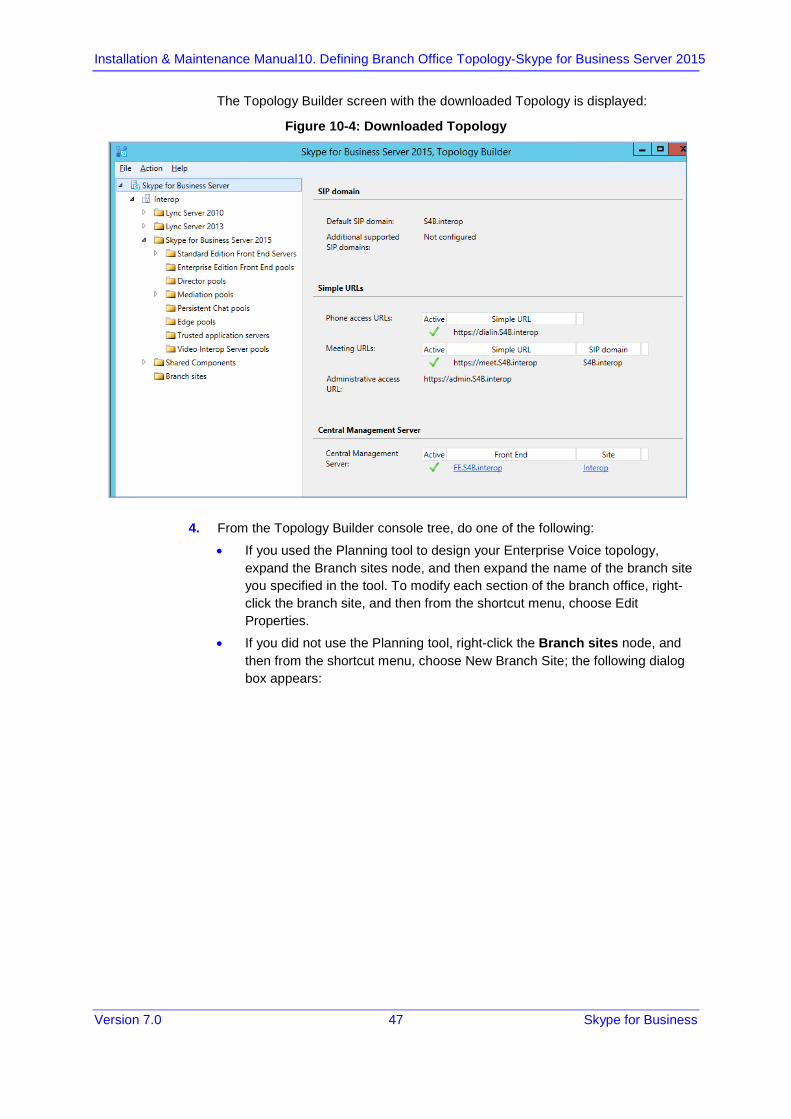
The Topology Builder screen with the downloaded Topology is displayed:
Figure 10-4: Downloaded Topology
4. From the Topology Builder console tree, do one of the following:
• If you used the Planning tool to design your Enterprise Voice topology, expand the Branch sites node, and then expand the name of the branch site you specified in the tool. To modify each section of the branch office, right-click the branch site, and then from the shortcut menu, choose Edit Properties.
• If you did not use the Planning tool, right-click the Branch sites node, and then from the shortcut menu, choose New Branch Site; the following dialog box appears:
Version 7.0 48 Document #: LTRT-39482
Mediant 2600B SBA
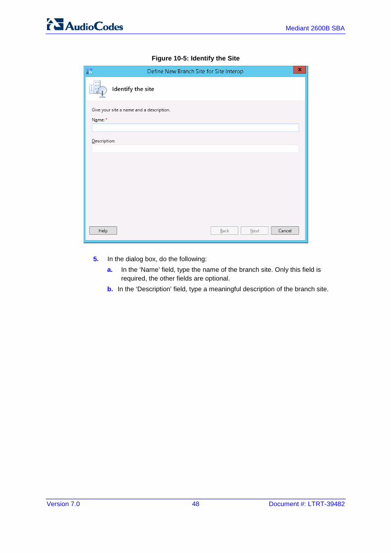
Figure 10-5: Identify the Site
5. In the dialog box, do the following: a. In the ‘Name’ field, type the name of the branch site. Only this field is
required, the other fields are optional. b. In the ‘Description’ field, type a meaningful description of the branch site.
Version 7.0 49 Skype for Business
Installation & Maintenance Manual 10. Defining Branch Office Topology-Skype for Business Server 2015
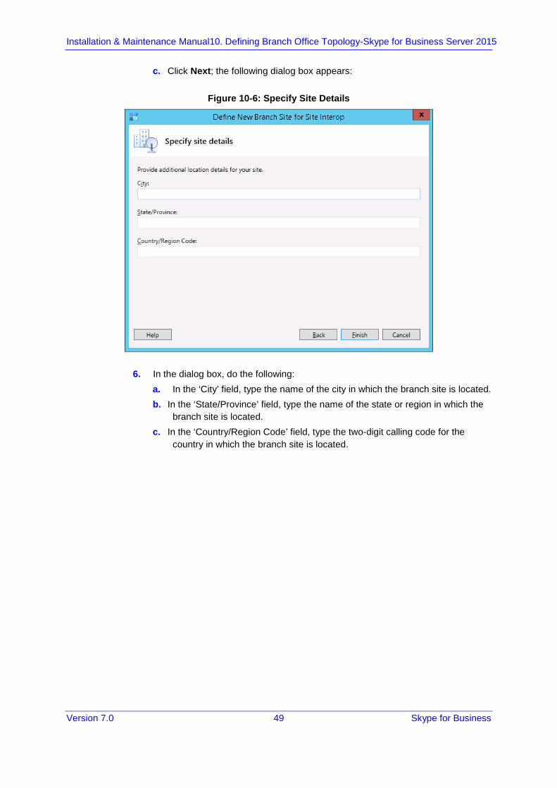
c. Click Next; the following dialog box appears:
Figure 10-6: Specify Site Details
6. In the dialog box, do the following: a. In the ‘City’ field, type the name of the city in which the branch site is located. b. In the ‘State/Province’ field, type the name of the state or region in which the
branch site is located. c. In the ‘Country/Region Code’ field, type the two-digit calling code for the
country in which the branch site is located.
Version 7.0 50 Document #: LTRT-39482
Mediant 2600B SBA
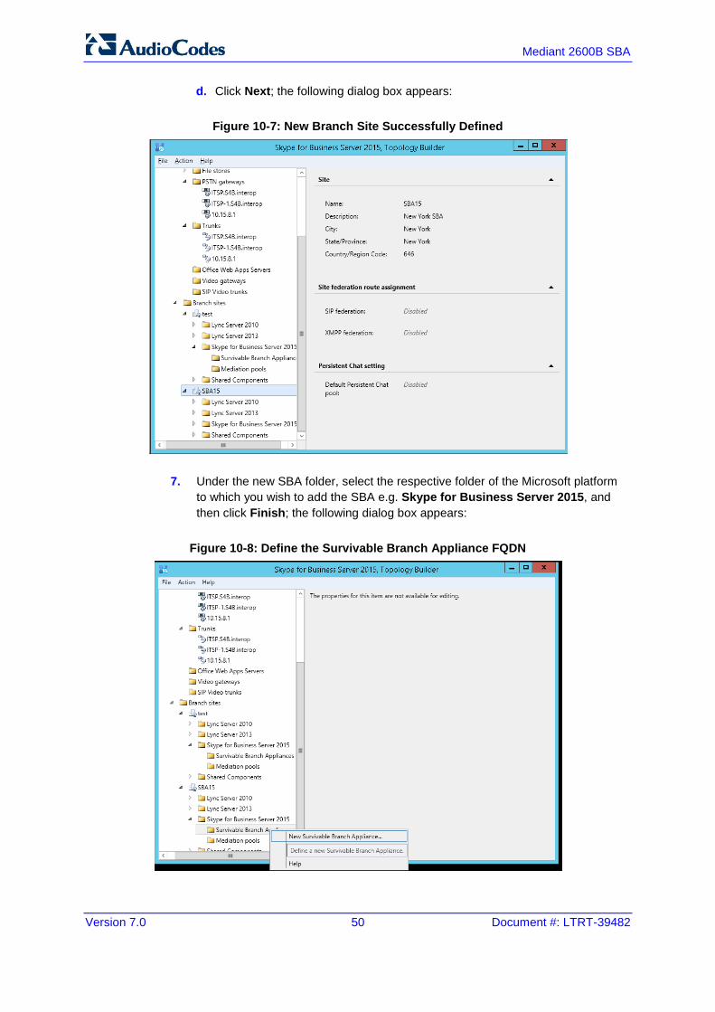
d. Click Next; the following dialog box appears:
Figure 10-7: New Branch Site Successfully Defined
7. Under the new SBA folder, select the respective folder of the Microsoft platform to which you wish to add the SBA e.g. Skype for Business Server 2015, and then click Finish; the following dialog box appears:
Figure 10-8: Define the Survivable Branch Appliance FQDN

Version 7.0 51 Skype for Business
Installation & Maintenance Manual 10. Defining Branch Office Topology-Skype for Business Server 2015
8. In the ‘FQDN’ field, type the FQDN of the SBA, and then click Next.
Figure 10-9: SBA FQDN
Note: The Survivable Branch Appliance FQDN parameter above should be identically configured in the E-SBC Proxy Set for Skype for Business 2015 (see Section 13.5 on page 156).
Version 7.0 52 Document #: LTRT-39482
Mediant 2600B SBA
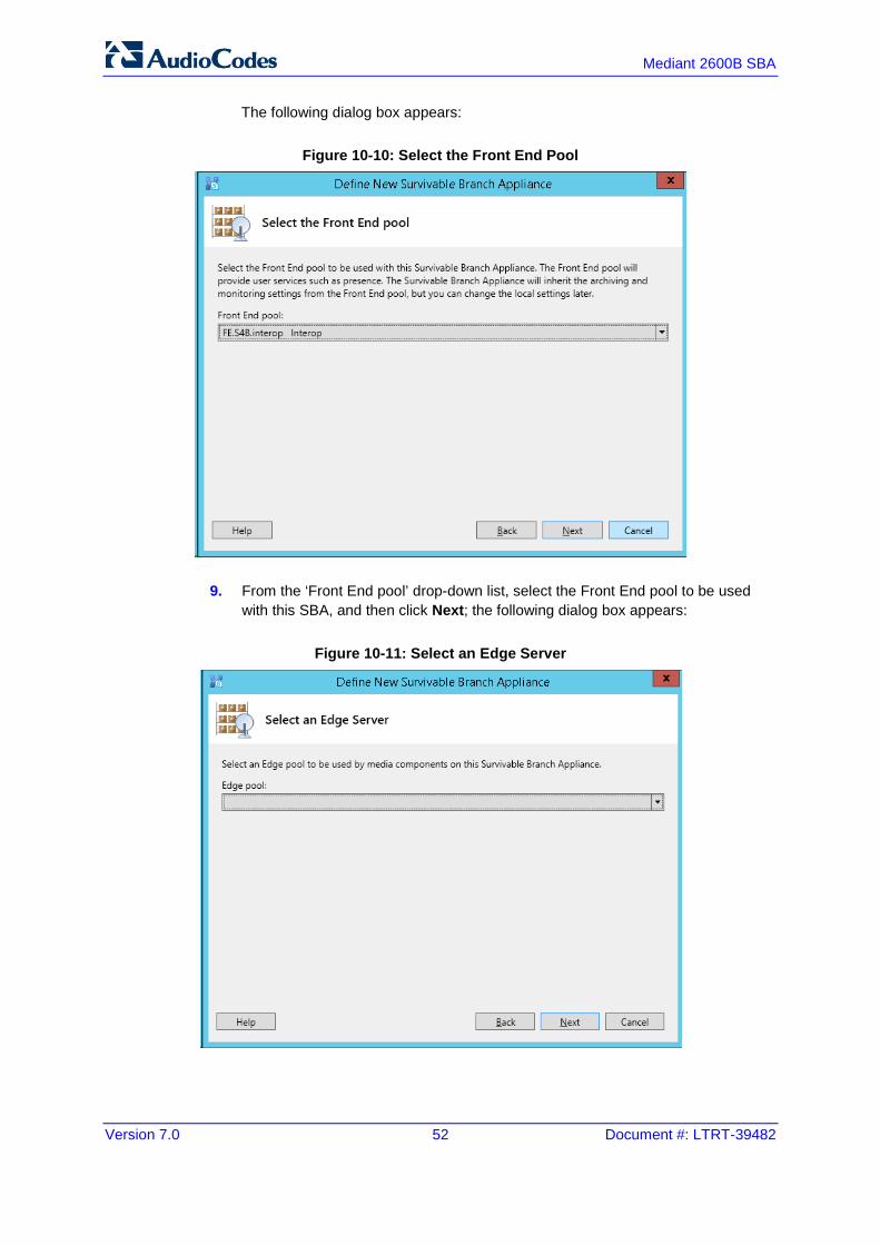
The following dialog box appears:
Figure 10-10: Select the Front End Pool
9. From the ‘Front End pool’ drop-down list, select the Front End pool to be used with this SBA, and then click Next; the following dialog box appears:
Figure 10-11: Select an Edge Server

Version 7.0 53 Skype for Business
Installation & Maintenance Manual 10. Defining Branch Office Topology-Skype for Business Server 2015
10. From the ‘Edge pool’ drop-down list, select the Edge pool to be used with this SBA (optional), and then click Next; the following dialog box example screens appear:
Figure 10-12: Define PSTN Gateway (E-SBC Device)
11. Enter the Fully Qualified Domain Name (FQDN) of the E-SBC (e.g.,
ITSP.S4B.interop). This FQDN should be identically configured the Subject Name (CN) in the TLS Certificate Context (see Section 13.9.3 on page 173).
The subsequent field "Define root trunk name" is automatically filled when you enter the FQDN. The definition of the trunk is a logical connection between the Mediation Server and an E-SBC uniquely identified by the following combination: Mediation Server FQDN, Mediation Server listening port (TLS or TCP), E-SBC IP and FQDN, and gateway listening port.
Note:
• When defining an E-SBC in the Topology Builder, you must define a root trunk to successfully add the E-SBC to your topology.
• The root trunk cannot be removed until the associated E-SBC is removed.
12. In the 'Listening Port for IP/PSTN Gateway' field, enter the listening port that the E-SBC will use for SIP messages from the Mediation Server that will be associated with the root trunk of the PSTN gateway (e.g., 5067). This parameter should be identically configured in the SIP Interface table (see Section 13.4 on page 154).

Version 7.0 54 Document #: LTRT-39482
Mediant 2600B SBA
13. In the 'SIP Transport Protocol' field, select the transport type (e.g., TLS) that the trunk uses. This parameter should be identically configured in the SIP Interface table (see Section 13.4 on page 154).
14. Click Finish. 15. The new SBA is added under the Survivable Branch Appliances folder as shown
below:
Figure 10-13: SBA Branch Successfully Created
16. Open the SBA branch Shared Components folder and you notice that the PSTN
Gateway (E-SBC device) and trunk objects have been added in the respective folders as shown in the example figure below:

Version 7.0 55 Skype for Business
Installation & Maintenance Manual 10. Defining Branch Office Topology-Skype for Business Server 2015
Figure 10-14: SBA Shared Components
17. Publish the Topology: In the main tree, select the root node Skype for Business Server, and then from the Action menu, choose Publish Topology, as shown below:

Version 7.0 56 Document #: LTRT-39482
Mediant 2600B SBA
Figure 10-15: Choosing Publish Topology

Version 7.0 57 Skype for Business
Installation & Maintenance Manual 10. Defining Branch Office Topology-Skype for Business Server 2015
The following is displayed:
Figure 10-16: Publish the Topology
18. Click Next; the Topology Builder starts to publish your topology, as shown below:
Figure 10-17: Publishing in Progress

Version 7.0 58 Document #: LTRT-39482
Mediant 2600B SBA
19. Wait until the publishing topology process completes successfully, as shown below:
Figure 10-18: Publishing Wizard Complete
20. Click Finish.

Version 7.0 59 Skype for Business
Installation & Maintenance Manual 10. Defining Branch Office Topology-Skype for Business Server 2015
10.2 Configuring the "Route" on Skype for Business Server 2015 The procedure below describes how to configure a "Route" on the Skype for Business Server 2015 and to associate it with the E-SBC PSTN gateway.
To configure the "route" on Skype for Business Server 2015:
1. Start the Microsoft Skype for Business Server 2015 Control Panel (Start > search for Microsoft Skype for Business Server Control Panel), as shown below:
Figure 10-19: Opening the Skype for Business Server Control Panel
Version 7.0 60 Document #: LTRT-39482
Mediant 2600B SBA
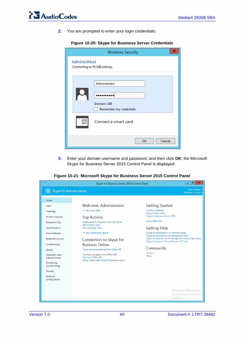
2. You are prompted to enter your login credentials:
Figure 10-20: Skype for Business Server Credentials
3. Enter your domain username and password, and then click OK; the Microsoft Skype for Business Server 2015 Control Panel is displayed:
Figure 10-21: Microsoft Skype for Business Server 2015 Control Panel
Version 7.0 61 Skype for Business
Installation & Maintenance Manual 10. Defining Branch Office Topology-Skype for Business Server 2015
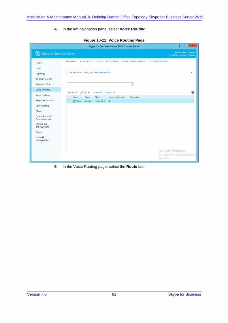
4. In the left navigation pane, select Voice Routing.
Figure 10-22: Voice Routing Page
5. In the Voice Routing page, select the Route tab.

Version 7.0 62 Document #: LTRT-39482
Mediant 2600B SBA
Figure 10-23: Route Tab
6. Click New; the New Voice Route page appears:
Figure 10-24: Adding New Voice Route

Version 7.0 63 Skype for Business
Installation & Maintenance Manual 10. Defining Branch Office Topology-Skype for Business Server 2015
7. In the 'Name' field, enter a name for this route (e.g., ITSP). 8. In the 'Starting digits for numbers that you want to allow' field, enter the starting
digits you want this route to handle (e.g., * to match all numbers), and then click Add.
9. Associate the route with the E-SBC Trunk that you created: a. Under the 'Associated Trunks' group, click Add; a list of all the deployed
gateways is displayed:
Figure 10-25: List of Deployed Trunks
b. Select the E-SBC Trunk you created, and then click OK; the trunk is added to the 'Associated Trunks' group list:
Version 7.0 64 Document #: LTRT-39482
Mediant 2600B SBA
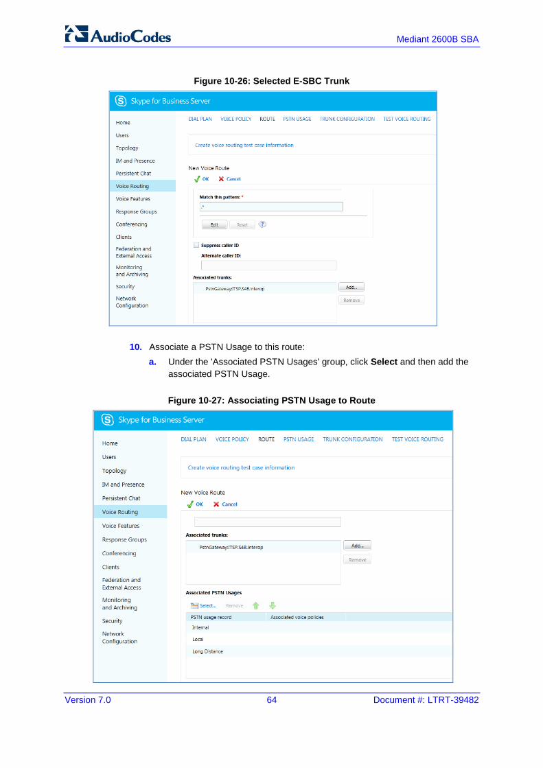
Figure 10-26: Selected E-SBC Trunk
10. Associate a PSTN Usage to this route: a. Under the 'Associated PSTN Usages' group, click Select and then add the
associated PSTN Usage.
Figure 10-27: Associating PSTN Usage to Route
Version 7.0 65 Skype for Business
Installation & Maintenance Manual 10. Defining Branch Office Topology-Skype for Business Server 2015
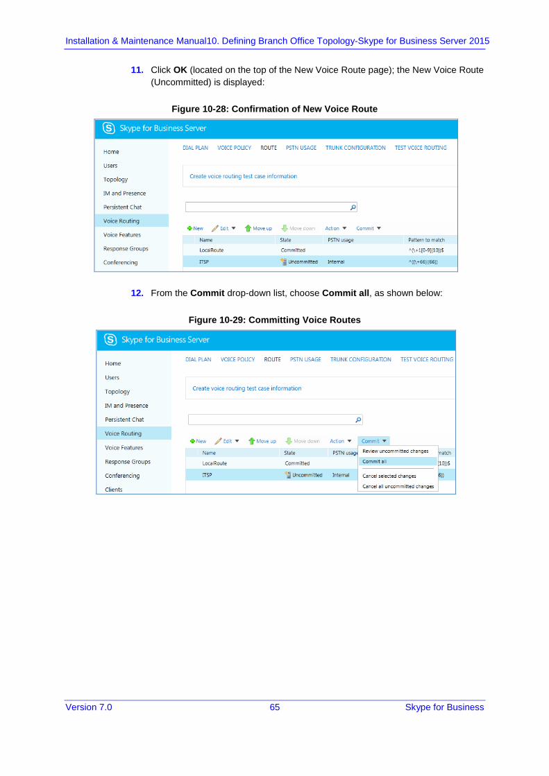
11. Click OK (located on the top of the New Voice Route page); the New Voice Route (Uncommitted) is displayed:
Figure 10-28: Confirmation of New Voice Route
12. From the Commit drop-down list, choose Commit all, as shown below:
Figure 10-29: Committing Voice Routes
Version 7.0 66 Document #: LTRT-39482
Mediant 2600B SBA
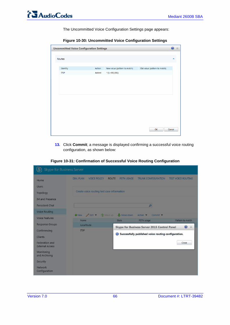
The Uncommitted Voice Configuration Settings page appears:
Figure 10-30: Uncommitted Voice Configuration Settings
13. Click Commit; a message is displayed confirming a successful voice routing configuration, as shown below:
Figure 10-31: Confirmation of Successful Voice Routing Configuration

Version 7.0 67 Skype for Business
Installation & Maintenance Manual 10. Defining Branch Office Topology-Skype for Business Server 2015
14. Click Close; the new committed Route is displayed in the Voice Routing page, as shown below:
Figure 10-32: Voice Routing Screen Displaying Committed Routes
15. For ITSPs that implement a call identifier, continue with the following steps:
Note: The SIP History-Info header provides a method to verify the identity (ID) of the call forwarder (i.e., the Skype for Business user number). This ID is required by Vendor SIP Trunk in the P-Asserted-Identity header. The device adds this ID to the P-Asserted-Identity header in the sent INVITE message using the IP Profile (later configured in Section 13.6 on page 160).
a. In the Voice Routing page, select the Trunk Configuration tab. Note that
you can add and modify trunk configuration by site or by pool.
Figure 10-33: Voice Routing Screen – Trunk Configuration Tab

Version 7.0 68 Document #: LTRT-39482
Mediant 2600B SBA
b. Click Edit; the Edit Trunk Configuration page appears:
Figure 10-34: Edit Trunk Configuration
c. Select the Enable forward call history check box, and then click OK.
16. Repeat Steps 11 through 13 to commit your settings.

Part IV Setting up the SBA with Management Interface
This part describes how to initially connect to the SBA's management interface and to install and configure it in the branch site.


Version 7.0 71 Skype for Business
Installation & Maintenance Manual 11. Connecting to the SBA Management Interface
11 Connecting to the SBA Management Interface The SBA Web-based, graphical user interface (GUI) tool is used for installing and configuring the SBA application running on the Mediant 2600B SBA OSN server.
Note: The SBA Management Interface is supported from Internet Explorer 9 and later (Compatibility disabled), Firefox, and Google Chrome.
You can initially connect the SBA to the network using one of the following methods:
Using the internal NIC: the SBA is connected to the network through the E-SBC Ethernet port and the devices internal switch. See below.
If this option is used, only a single network cable is required (for connecting to the E-SBC Ethernet port).
Using the external NIC: the SBA is connected to the network through the GE port on the OSN server. See Section 11.2.
If this option is used, two network cables are required; one for connecting to the OSN server GE port and the other for connecting to the E-SBC application GE port.
11.1 Connecting to SBA Using the Internal NIC When you initially connect to the SBA using the internal NIC, the network cable should be connected to one of the E-SBC Ethernet ports on the device's front panel; this port connects to the device's internal switch, which then connects to the OSN module. When this option is used, there is no pre-configured factory default IP address, and therefore the network address must be acquired using DHCP or assigned with a static IP address.
To initially connect to the SBA using the internal NIC:
1. Connect the first Ethernet port on the SBC module on the front panel of the device directly to the network using a straight-through Ethernet cable.
Figure 11-1: Connecting Mediant 2600B SBA LAN Port (Front Panel)

Mediant 2600B SBA
Version 7.0 72 Document #: LTRT-39482
2. If you wish to monitor the connection process via an HDMI monitor, do the following (otherwise skip to Step 3):
a. Connect a USB hub to the USB port located on the OSN4 module, and then connect the USB hub to the following computer peripherals: ♦ Mouse ♦ Keyboard
b. Using the supplied MINI HDMI TO HDMI 1.5m cable, connect the Micro HDMI port on the OSN4 module using a Mini HDMI connector and connect the other end to the HDMI port on the monitor using a Type-D male connector. For HDMI connector cable pinouts (see Section 3.1.3 for HDMI cable connector pinouts).
Figure 11-2: Cabling OSN4 Module with HDMI Monitor
c. Determine the NIC used for the Ethernet port, by removing the network cable from the Ethernet port and viewing on the monitor that the NIC (ID) has changed to "Disconnected". This is the NIC corresponding to the Ethernet LAN port.
d. Reconnect the network cable and then do one of the following: ♦ If you have a DHCP server in your network, note the IP address
assigned to the Ethernet LAN port. ♦ If you are not using a DHCP server, then assign a static IP address to
the NIC of the Ethernet LAN port.
e. Proceed to Step 10.
3. Connect a serial cable with a micro-USB connector on one end to the serial port (labeled IOIOI) on the OSN4 module.

Version 7.0 73 Skype for Business
Installation & Maintenance Manual 11. Connecting to the SBA Management Interface
4. Connect the other end of the cable to the COM port on your computer.
Figure 11-3: Cabling OSN4 Module for Serial Communication
Note: For the Mediant 2600B SBA OSN serial interface port (micro-USB) to be operational, you must download a special USB driver from the Internet. Download this driver at:
• http://www.silabs.com/products/mcu/pages/usbtouartbridgevcpdrivers.aspx • http:/www.silabs.com/products/mcu/pages/usbtouartbridgevcpdrivers.aspx
5. Establish serial communication with the OSN server through a terminal emulation program (such as HyperTerminal) using the following serial communication settings:
• Baud Rate: 115200 (bits per second)
• Data Bits: 8
• Parity: None
• Stop Bits: 1
• Flow Control: None 6. Press Enter; the Serial Console prompt is displayed:
SAC>
7. Type the following to view all the NIC addresses:
SAC>i
8. Do one of the following:
• If you have a DHCP server in your network, the internal NIC should be identified by a displayed IP address (the two external Ethernet LAN ports should be displayed as "Disconnected").

Mediant 2600B SBA
Version 7.0 74 Document #: LTRT-39482
• If you are not using a DHCP server, assign a static IP address to the NIC of the internal Ethernet LAN port using the following command and then press Enter to apply your settings:
i <NIC ID> <IP address> <subnet> <default gateway>
9. Disconnect the serial cable from the OSN server. 10. Open a standard Web browser (Firefox, Google Chrome, or Internet Explorer 9
and later is recommended), and then in the URL address field, enter the IP address that you determined above. The Survivable Branch Appliance Management Interface opens:
Figure 11-4: Welcome to SBA

Version 7.0 75 Skype for Business
Installation & Maintenance Manual 11. Connecting to the SBA Management Interface
11. Log in with the default username ("Administrator") and password ("Pass123"), Select the "Yes, I accept the term and condition" checkbox, and then click Login; the Home screen appears:
Figure 11-5: SBA Home Screen
12. Change the default IP address of the SBA Management Interface to suit your network environment (see page 81).

Mediant 2600B SBA
Version 7.0 76 Document #: LTRT-39482
11.2 Connecting to the SBA Using the External NIC When you initially connect to the SBA using the external NIC, the network cable should be connected to Ethernet port 1 on the OSN module. The SBA Management Interface is initially accessed using the pre-configured factory default IP address of the OSN server (192.168.0.20/16). You can then use the SBA Management interface to change this default IP address to suit your network environment.
To initially connect to the SBA using the external NIC:
1. Connect an RJ-45 connector, on one end of a CAT 5 (5e or 6) cable to Ethernet port 1 on the OSN4 module. Connect the other end of the cable to your PC .
Figure 11-6: Cabling OSN4 Module to Network
For RJ-45 connector pinouts for the Gigabit Ethernet interface, see Section 3.1.2.

Version 7.0 77 Skype for Business
Installation & Maintenance Manual 11. Connecting to the SBA Management Interface
2. Change your computer’s IP address so that it is in the same subnet as the default IP address of the OSN server hosting the SBA.
3. Open a standard Web browser (Firefox, Google Chrome, or Internet Explorer 9 and later is recommended), and then in the URL address field, enter the OSN server default IP address (192.168.0.20/16). The Survivable Branch Appliance Management Interface opens:
Figure 11-7: Welcome to SBA
4. Log in with the default username ("Administrator") and password ("Pass123"), Select the "Yes, I accept the term and condition" checkbox and then click Login; the Home screen appears:
Figure 11-8: SBA Home Screen
5. Change the default IP address of the SBA Management Interface to suit your network environment (see Section 'Step 1: Define IP Settings' on page 80).

Mediant 2600B SBA
Version 7.0 78 Document #: LTRT-39482
Version 7.0 79 Skype for Business
Installation & Maintenance Manual 12. Installing and Configuring the SBA
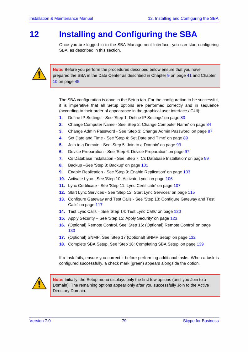
12 Installing and Configuring the SBA Once you are logged in to the SBA Management Interface, you can start configuring SBA, as described in this section.
Note: Before you perform the procedures described below ensure that you have prepared the SBA in the Data Center as described in Chapter 9 on page 41 and Chapter 10 on page 45.
The SBA configuration is done in the Setup tab. For the configuration to be successful, it is imperative that all Setup options are performed correctly and in sequence (according to their order of appearance in the graphical user interface / GUI): 1. Define IP Settings - See 'Step 1: Define IP Settings' on page 80 2. Change Computer Name - See 'Step 2: Change Computer Name' on page 84 3. Change Admin Password - See 'Step 3: Change Admin Password' on page 87 4. Set Date and Time - See 'Step 4: Set Date and Time' on page 89 5. Join to a Domain - See 'Step 5: Join to a Domain' on page 93 6. Device Preparation - See 'Step 6: Device Preparation' on page 97 7. Cs Database Installation - See 'Step 7: Cs Database Installation' on page 99 8. Backup –See 'Step 8: Backup' on page 101 9. Enable Replication - See 'Step 9: Enable Replication' on page 103 10. Activate Lync - See 'Step 10: Activate Lync' on page 106 11. Lync Certificate - See 'Step 11: Lync Certificate' on page 107 12. Start Lync Services - See 'Step 12: Start Lync Services' on page 115 13. Configure Gateway and Test Calls - See 'Step 13: Configure Gateway and Test
Calls' on page 117 14. Test Lync Calls – See 'Step 14: Test Lync Calls' on page 120 15. Apply Security – See 'Step 15: Apply Security' on page 123 16. (Optional) Remote Control. See 'Step 16: (Optional) Remote Control' on page
130 17. (Optional) SNMP. See 'Step 17 (Optional) SNMP Setup' on page 132 18. Complete SBA Setup. See 'Step 18: Completing SBA Setup' on page 139 If a task fails, ensure you correct it before performing additional tasks. When a task is configured successfully, a check mark (green) appears alongside the option.
Note: Initially, the Setup menu displays only the first few options (until you Join to a Domain). The remaining options appear only after you successfully Join to the Active Directory Domain.
Mediant 2600B SBA
Version 7.0 80 Mediant 2600B SBA
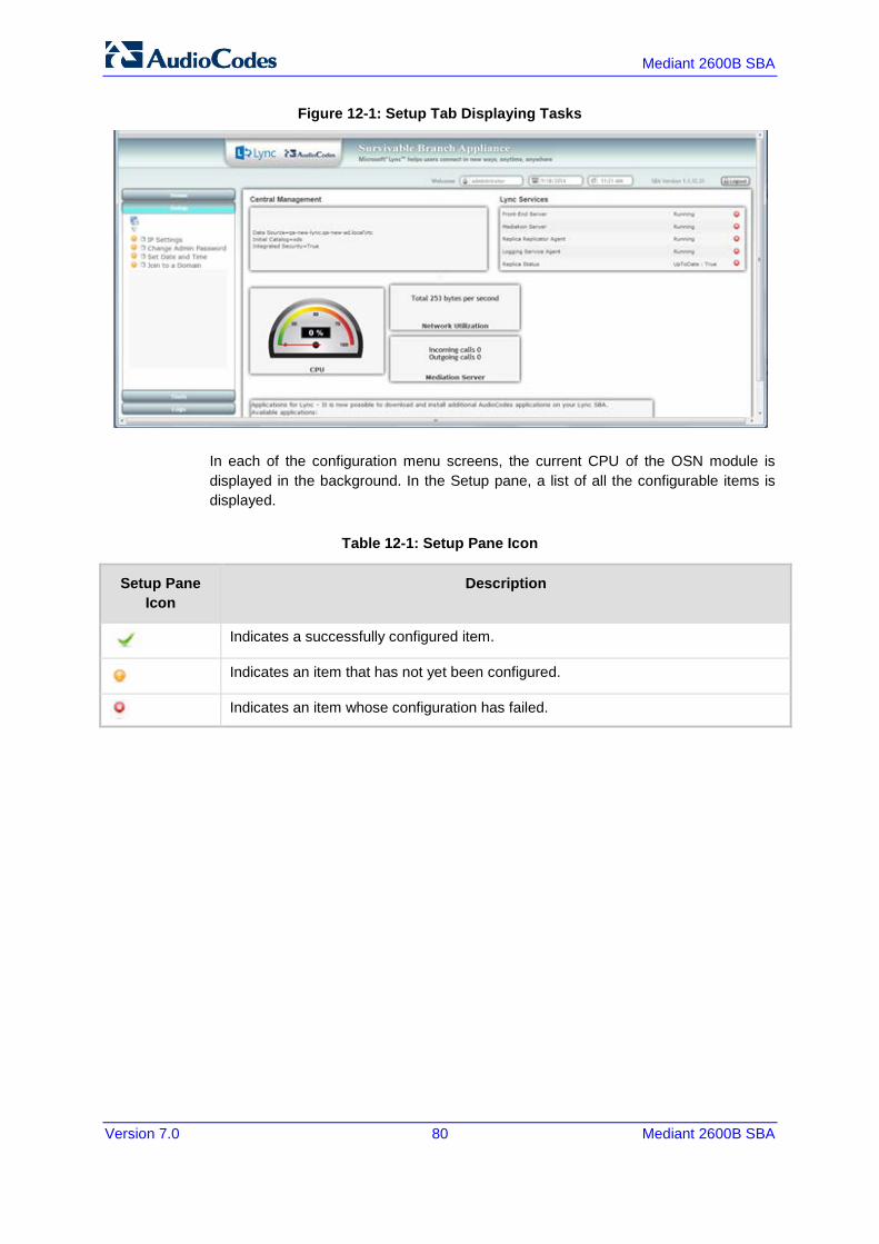
Figure 12-1: Setup Tab Displaying Tasks
In each of the configuration menu screens, the current CPU of the OSN module is displayed in the background. In the Setup pane, a list of all the configurable items is displayed.
Table 12-1: Setup Pane Icon
Setup Pane Icon
Description
Indicates a successfully configured item.
Indicates an item that has not yet been configured.
Indicates an item whose configuration has failed.
Version 7.0 81 Skype for Business
Installation & Maintenance Manual 12. Installing and Configuring the SBA
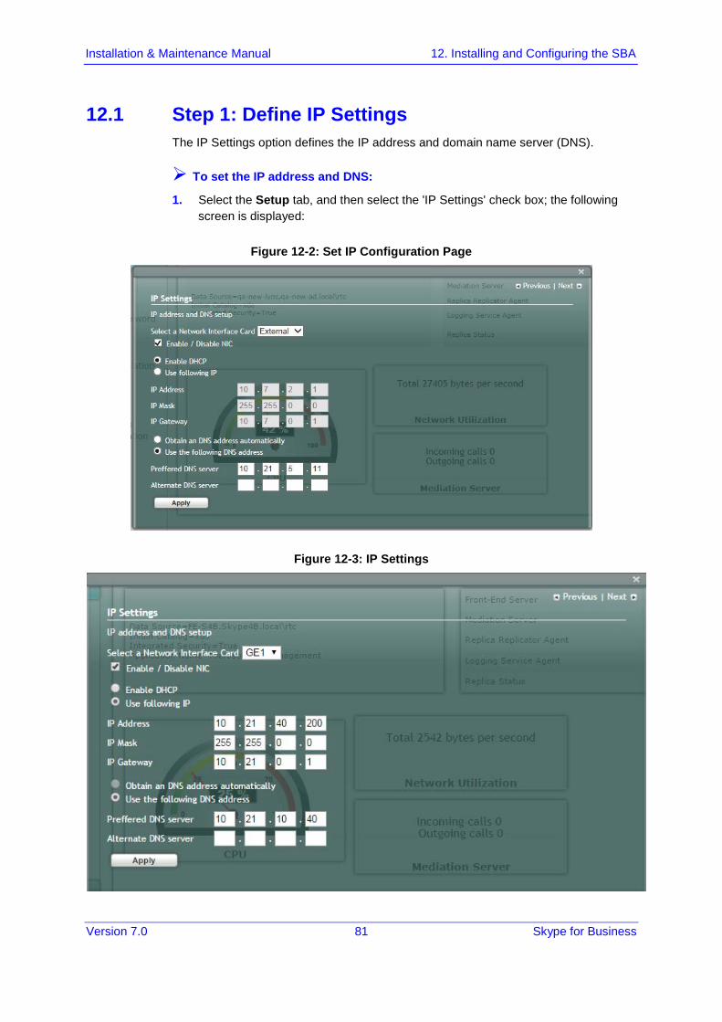
12.1 Step 1: Define IP Settings The IP Settings option defines the IP address and domain name server (DNS).
To set the IP address and DNS:
1. Select the Setup tab, and then select the 'IP Settings' check box; the following screen is displayed:
Figure 12-2: Set IP Configuration Page
Figure 12-3: IP Settings
Mediant 2600B SBA
Version 7.0 82 Mediant 2600B SBA
2. Clear the 'Enable / Disable NIC' check box for those interfaces that you are not using.
3. From the drop-down list, select one of the following NIC interface options:
• External1 – Corresponds to one of the physical Ethernet ports on the Mediant 2600B rear panel.
• External2 – Corresponds to one of the physical Ethernet ports on the Mediant 2600B rear panel.
• Internal1 – Internal port that connects the OSN server to the gateway's SBC module.
• Internal2 – Internal port that is not in use.
Note: The assignment of the physical ports (Port 1 and Port 2) to the External1 and External2 NICs is random.
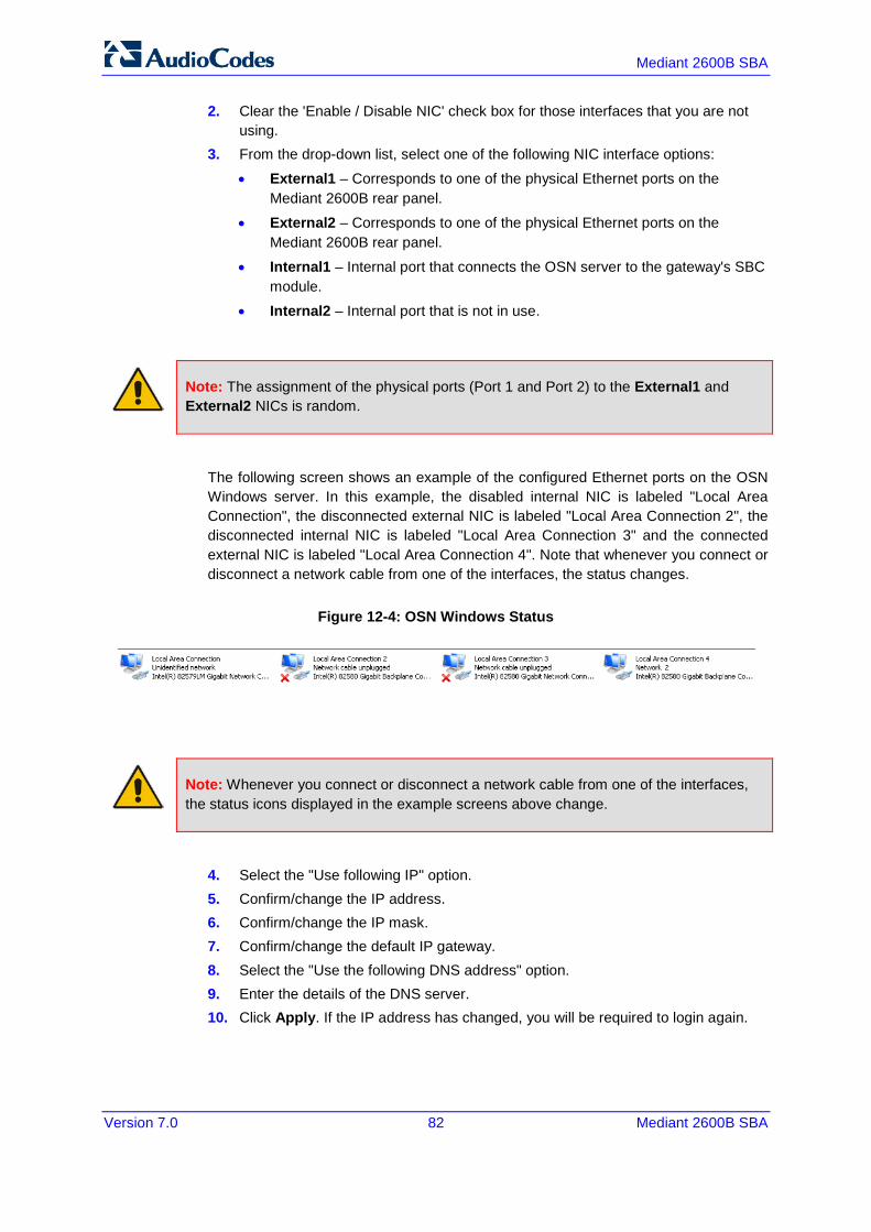
The following screen shows an example of the configured Ethernet ports on the OSN Windows server. In this example, the disabled internal NIC is labeled "Local Area Connection", the disconnected external NIC is labeled "Local Area Connection 2", the disconnected internal NIC is labeled "Local Area Connection 3" and the connected external NIC is labeled "Local Area Connection 4". Note that whenever you connect or disconnect a network cable from one of the interfaces, the status changes.
Figure 12-4: OSN Windows Status
Note: Whenever you connect or disconnect a network cable from one of the interfaces, the status icons displayed in the example screens above change.
4. Select the "Use following IP" option. 5. Confirm/change the IP address. 6. Confirm/change the IP mask. 7. Confirm/change the default IP gateway. 8. Select the "Use the following DNS address" option. 9. Enter the details of the DNS server. 10. Click Apply. If the IP address has changed, you will be required to login again.

Version 7.0 83 Skype for Business
Installation & Maintenance Manual 12. Installing and Configuring the SBA
Figure 12-5: IP Settings - Login Again
11. Click OK. A new login screen appears. 12. Enter the Username, Password and then click Login.
Notes:
• The system logs in with the new IP address. • Every time you change the NIC interface option, click Apply for the change to take
effect.
A green check mark is displayed next to the 'IP Settings' option under the Setup tab, as shown in the figure below.

Mediant 2600B SBA
Version 7.0 84 Mediant 2600B SBA
Figure 12-6: IP Settings Complete
12.2 Step 2: Change Computer Name The Change Computer Name option defines the computer name of the SBA.
Note:
• This procedure requires you to reboot the SBA server to successfully apply the configuration. However, if you forget to do so, the server automatically reboots after a session timeout. When this occurs, the login screen appears with the following popup message: "The SBA server needs to be rebooted. Please insert your credentials and click Login. The server will then be rebooted". After the server reboots, the following message appears: "The SBA server has been rebooted automatically". You can then login to the SBA Management Interface.
• Once you join to the Domain, this configuration option is only available when you login as a local user (not a Domain user).

Version 7.0 85 Skype for Business
Installation & Maintenance Manual 12. Installing and Configuring the SBA
To change the computer name of the SBA server:
1. Select the Setup tab, and then select the 'Change Computer Name' check box; the following screen appears:
Figure 12-7: Change Computer Name Screen
2. In the 'Computer Name' field, enter the computer name.
Note: The Computer Name must be the same as that used for the SBA in the Microsoft Active Directory (AD) and Topology during the pre-configuration steps performed at the datacenter (see Chapter '1' on page 41 and Chapter '1' on page 45).
Mediant 2600B SBA
Version 7.0 86 Mediant 2600B SBA
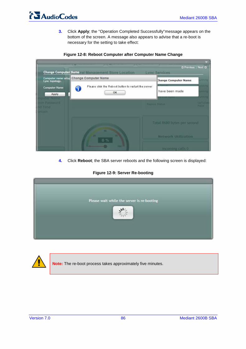
3. Click Apply; the ''Operation Completed Successfully''message appears on the bottom of the screen. A message also appears to advise that a re-boot is necessary for the setting to take effect:
Figure 12-8: Reboot Computer after Computer Name Change
4. Click Reboot; the SBA server reboots and the following screen is displayed:
Figure 12-9: Server Re-booting
Note: The re-boot process takes approximately five minutes.

Version 7.0 87 Skype for Business
Installation & Maintenance Manual 12. Installing and Configuring the SBA
When the SBA completes its reboot, the Welcome to SBA screen appears again.
Figure 12-10: Login Screen
5. Enter your username and password and then click Login to log in once again to the SBA Management Interface; the Setup tab appears, displaying a green check mark next to the 'Change Computer Name' option, as shown in the figure below.
Figure 12-11: Change Computer Name – Completed Successfully

Mediant 2600B SBA
Version 7.0 88 Mediant 2600B SBA
12.3 Step 3: Change Admin Password The Change Admin Password option resets the local Administrator password.
To change the Administrator password:
1. Select the Setup tab, and then select the 'Change Admin Password' check box; the following screen is displayed:
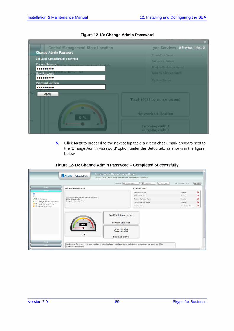
Figure 12-12: Change Admin Password Screen
2. In the 'Current Password' field, enter the current password. 3. In the 'New Password’ field', enter a new password, and then in the 'Password
Confirm' field, enter the new password again. 4. Click Apply; the following screen appears:
Version 7.0 89 Skype for Business
Installation & Maintenance Manual 12. Installing and Configuring the SBA
Figure 12-13: Change Admin Password
5. Click Next to proceed to the next setup task; a green check mark appears next to the 'Change Admin Password' option under the Setup tab, as shown in the figure below.
Figure 12-14: Change Admin Password – Completed Successfully

Mediant 2600B SBA
Version 7.0 90 Mediant 2600B SBA
12.4 Step 4: Set Date and Time The Set Date and Time option resets the date and time zone.
To set the date and time:
1. Select the Setup tab, and then select the 'Set Date and Time' check box; the following screen is displayed:
Figure 12-15: Set Date and Time Screen

Version 7.0 91 Skype for Business
Installation & Maintenance Manual 12. Installing and Configuring the SBA
2. Select the Time Zone tab; the following screen appears:
Figure 12-16: Set Date and Time - Time Zone
3. From the drop-down list, select the appropriate time zone. 4. Select the Date tab, and then define the date and time. 5. Click Apply; the "Operation Completed Successfully" message appears on the
bottom of the screen.

Mediant 2600B SBA
Version 7.0 92 Mediant 2600B SBA
6. Click Apply; a notification message box appears:
Figure 12-17: Set Date and Time- Notification Message
7. Click OK; the following confirmation screen appears:
8. Click Next to proceed to the next setup task.
Version 7.0 93 Skype for Business
Installation & Maintenance Manual 12. Installing and Configuring the SBA
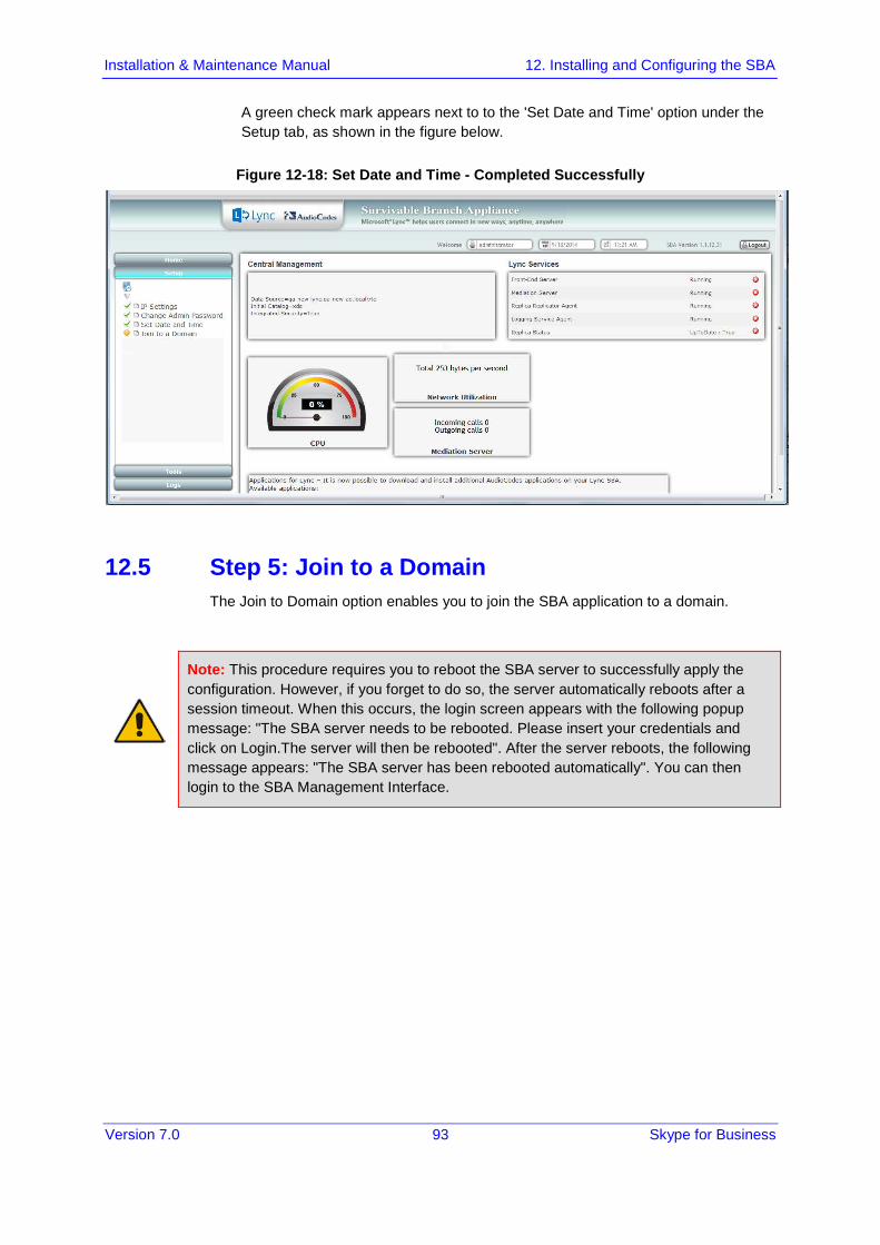
A green check mark appears next to to the 'Set Date and Time' option under the Setup tab, as shown in the figure below.
Figure 12-18: Set Date and Time - Completed Successfully
12.5 Step 5: Join to a Domain The Join to Domain option enables you to join the SBA application to a domain.
Note: This procedure requires you to reboot the SBA server to successfully apply the configuration. However, if you forget to do so, the server automatically reboots after a session timeout. When this occurs, the login screen appears with the following popup message: "The SBA server needs to be rebooted. Please insert your credentials and click on Login.The server will then be rebooted". After the server reboots, the following message appears: "The SBA server has been rebooted automatically". You can then login to the SBA Management Interface.
Mediant 2600B SBA
Version 7.0 94 Mediant 2600B SBA
To join the SBA application to a domain:
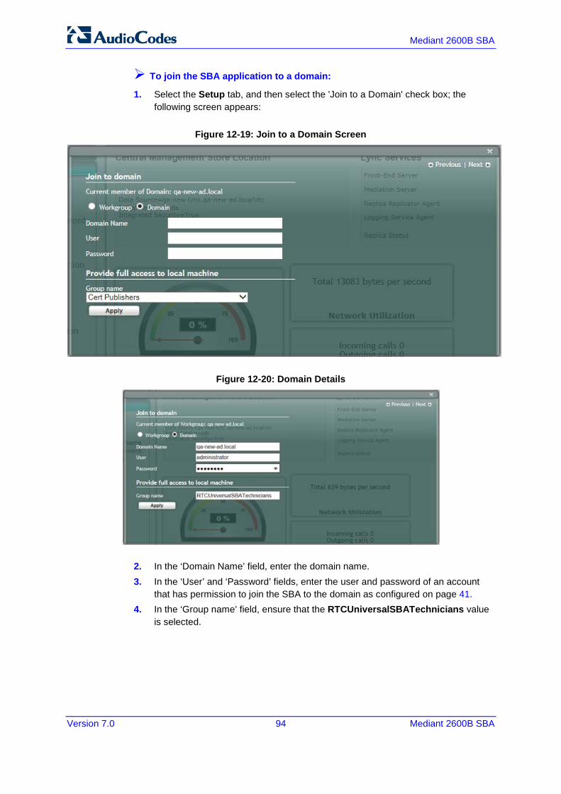
1. Select the Setup tab, and then select the 'Join to a Domain' check box; the following screen appears:
Figure 12-19: Join to a Domain Screen
Figure 12-20: Domain Details
2. In the ‘Domain Name’ field, enter the domain name. 3. In the ‘User’ and ‘Password’ fields, enter the user and password of an account
that has permission to join the SBA to the domain as configured on page 41. 4. In the ‘Group name’ field, ensure that the RTCUniversalSBATechnicians value
is selected.
Version 7.0 95 Skype for Business
Installation & Maintenance Manual 12. Installing and Configuring the SBA
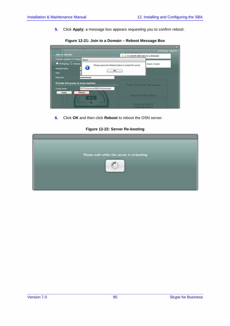
5. Click Apply; a message box appears requesting you to confirm reboot:
Figure 12-21: Join to a Domain – Reboot Message Box
6. Click OK and then click Reboot to reboot the OSN server.
Figure 12-22: Server Re-booting
Mediant 2600B SBA
Version 7.0 96 Mediant 2600B SBA
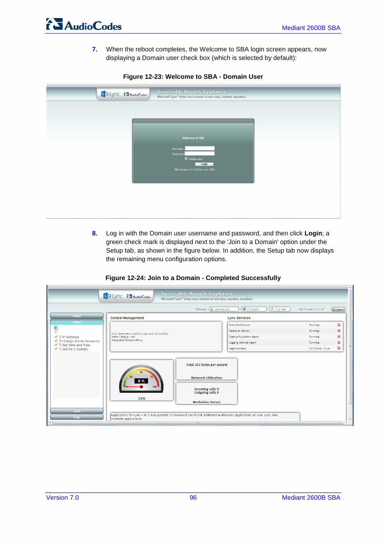
7. When the reboot completes, the Welcome to SBA login screen appears, now displaying a Domain user check box (which is selected by default):
Figure 12-23: Welcome to SBA - Domain User
8. Log in with the Domain user username and password, and then click Login; a green check mark is displayed next to the 'Join to a Domain' option under the Setup tab, as shown in the figure below. In addition, the Setup tab now displays the remaining menu configuration options.
Figure 12-24: Join to a Domain - Completed Successfully

Version 7.0 97 Skype for Business
Installation & Maintenance Manual 12. Installing and Configuring the SBA
12.6 Step 6: Device Preparation The Device Preparation menu option completes the SQL preparation and installs the Skype for Business components.
Note: This procedure requires you to reboot the SBA server to successfully apply the configuration. However, if you forget to do so, the server automatically reboots after a session timeout. When this occurs, the login screen appears with the following popup message: "The SBA server needs to be rebooted. Please insert your credentials and click on Login.The server will then be rebooted". After the server reboots, the following message appears: "The SBA server has been rebooted automatically". You can then login to the SBA Management Interface.
To prepare the device:
1. Select the Setup tab, and then select the 'Device Preparation' check box; the following screen appears:
Figure 12-25: Device Preparation

Mediant 2600B SBA
Version 7.0 98 Mediant 2600B SBA
2. Click Apply; the SQL installation begins, and the following screens appear in sequence as the SQL installation progresses. You can view a detailed log after each installation phase, by clicking the Detailed Log link.
Figure 12-26: Device Preparation Started
Figure 12-27: Device Preparation – All Components Installed
Version 7.0 99 Skype for Business
Installation & Maintenance Manual 12. Installing and Configuring the SBA
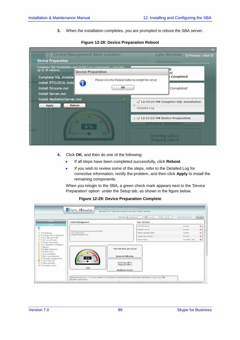
3. When the installation completes, you are prompted to reboot the SBA server.
Figure 12-28: Device Preparation Reboot
4. Click OK, and then do one of the following:
• If all steps have been completed successfully, click Reboot. • If you wish to review some of the steps, refer to the Detailed Log for
corrective information, rectify the problem, and then click Apply to install the remaining components.
When you relogin to the SBA, a green check mark appears next to the 'Device Preparation' option under the Setup tab, as shown in the figure below.
Figure 12-29: Device Preparation Complete

Mediant 2600B SBA
Version 7.0 100 Mediant 2600B SBA
12.7 Step 7: Cs Database Installation The Cs Database installation option installs CsDatabase for Lyss and registrar.
Note: This step is not relevant for Microsoft Lync Server 2010 deployments.
To install the CsDatabase:
1. Select the Setup tab, and then select the 'Cs Database installation' check box; the following screen appears:
Figure 12-30: Cs Database Installation Screen
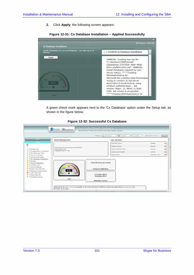
Version 7.0 101 Skype for Business
Installation & Maintenance Manual 12. Installing and Configuring the SBA
2. Click Apply; the following screen appears:
Figure 12-31: Cs Database Installation – Applied Successfully
A green check mark appears next to the 'Cs Database' option under the Setup tab, as shown in the figure below.
Figure 12-32: Successful Cs Database

Mediant 2600B SBA
Version 7.0 102 Mediant 2600B SBA
12.8 Step 8: Backup The Backup option creates a backup copy of the Central Management Server on the SBA server.
To create a backup of the Central Management Server:
1. Select the Setup tab, and then select the 'Backup' check box; the following screen appears:
Figure 12-33: Backup screen
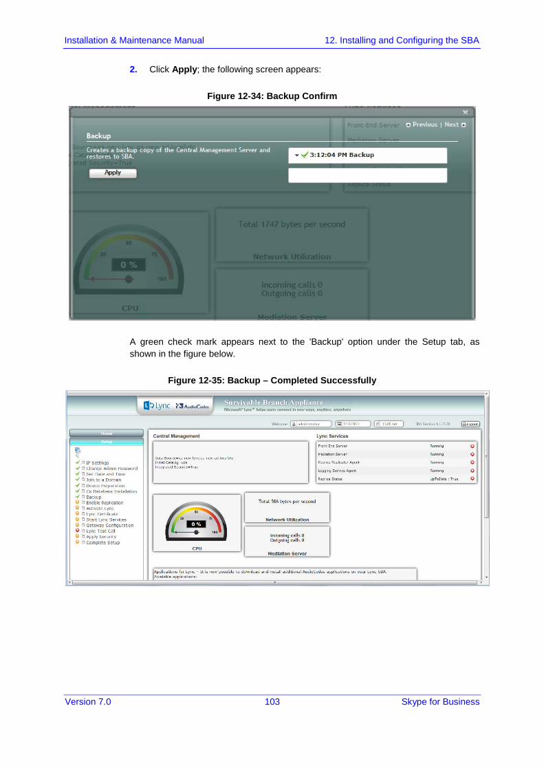
Version 7.0 103 Skype for Business
Installation & Maintenance Manual 12. Installing and Configuring the SBA
2. Click Apply; the following screen appears:
Figure 12-34: Backup Confirm
A green check mark appears next to the 'Backup' option under the Setup tab, as shown in the figure below.
Figure 12-35: Backup – Completed Successfully

Mediant 2600B SBA
Version 7.0 104 Mediant 2600B SBA
12.9 Step 9: Enable Replication The 'Enable Replication' option enables the replication process with the Central Management Server. The actual replication is executed after all Lync services have been enabled.
To enable replication:
1. Select the Setup tab, and then select the 'Enable Replication' check box; the following screen appears:
Figure 12-36: Enable Replication

Version 7.0 105 Skype for Business
Installation & Maintenance Manual 12. Installing and Configuring the SBA
2. Click Apply; the following screen appears:
Figure 12-37: Enable Replication – Applied Successfully
A green check mark appears next to the 'Enable Replication' option under the Setup tab, as shown in the figure below.
Figure 12-38: Enable Replication – Applied Successfully
Note: The replication status may not immiediately display the status "Up to Date-True or "Up to Date-False. These statuses should be displayed at a later stage in the configuration process.

Mediant 2600B SBA
Version 7.0 106 Mediant 2600B SBA
12.10 Step 10: Activate Lync The Activate Lync option activates the SBA server machine to run a Lync server 2013 service role. Installing the required software does not automatically cause the SBA server machine to adopt a new service role; instead, it must be activated before it actually begins to function in its new role.
To activate Lync:
1. Select the Setup tab, and then select the 'Activate Lync' check box; the following screen appears:
Figure 12-39: Activate Lync
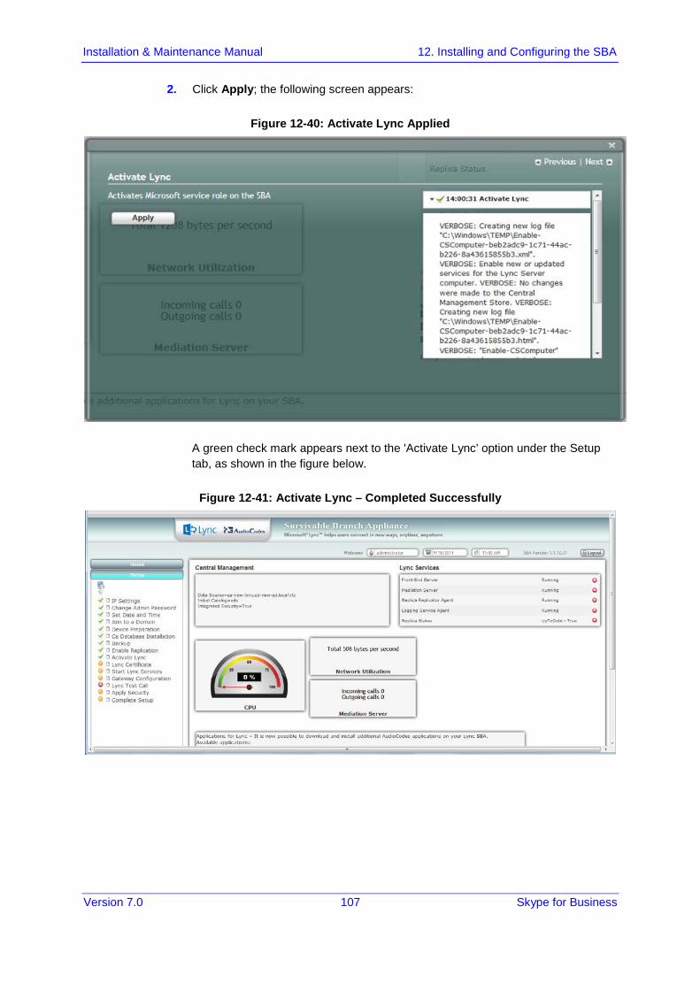
Version 7.0 107 Skype for Business
Installation & Maintenance Manual 12. Installing and Configuring the SBA
2. Click Apply; the following screen appears:
Figure 12-40: Activate Lync Applied
A green check mark appears next to the 'Activate Lync' option under the Setup tab, as shown in the figure below.
Figure 12-41: Activate Lync – Completed Successfully

Mediant 2600B SBA
Version 7.0 108 Mediant 2600B SBA
12.11 Step 11: Lync Certificate The 'Lync Certificate' option installs a certificate from the domain’s certificate authority. This certificate is used to secure the connection between the SBA server and the Central Management Server.
To install a Certificate:
Select the Setup tab, and then select the 'Lync Certificate' check box; the following screen appears:
Figure 12-42: Lync Certificate
Certificates can be installed either by importing an existing certificate or requesting a new certificate.
To import an existing certificate:
1. Select the Import Certification radio button. 2. Click Browse to select the File to Upload. 3. Enter the Password (optional) of the certificates. 4. Click Apply.
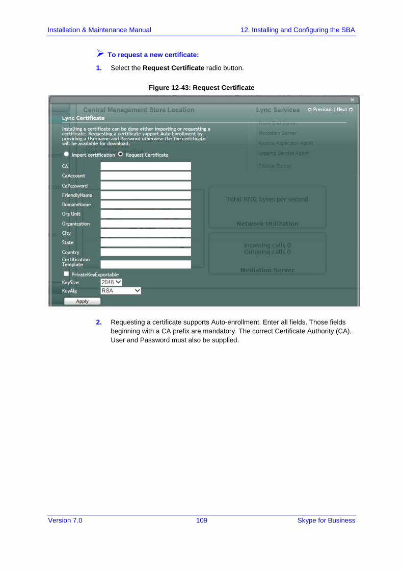
Version 7.0 109 Skype for Business
Installation & Maintenance Manual 12. Installing and Configuring the SBA
To request a new certificate:
1. Select the Request Certificate radio button.
Figure 12-43: Request Certificate
2. Requesting a certificate supports Auto-enrollment. Enter all fields. Those fields beginning with a CA prefix are mandatory. The correct Certificate Authority (CA), User and Password must also be supplied.
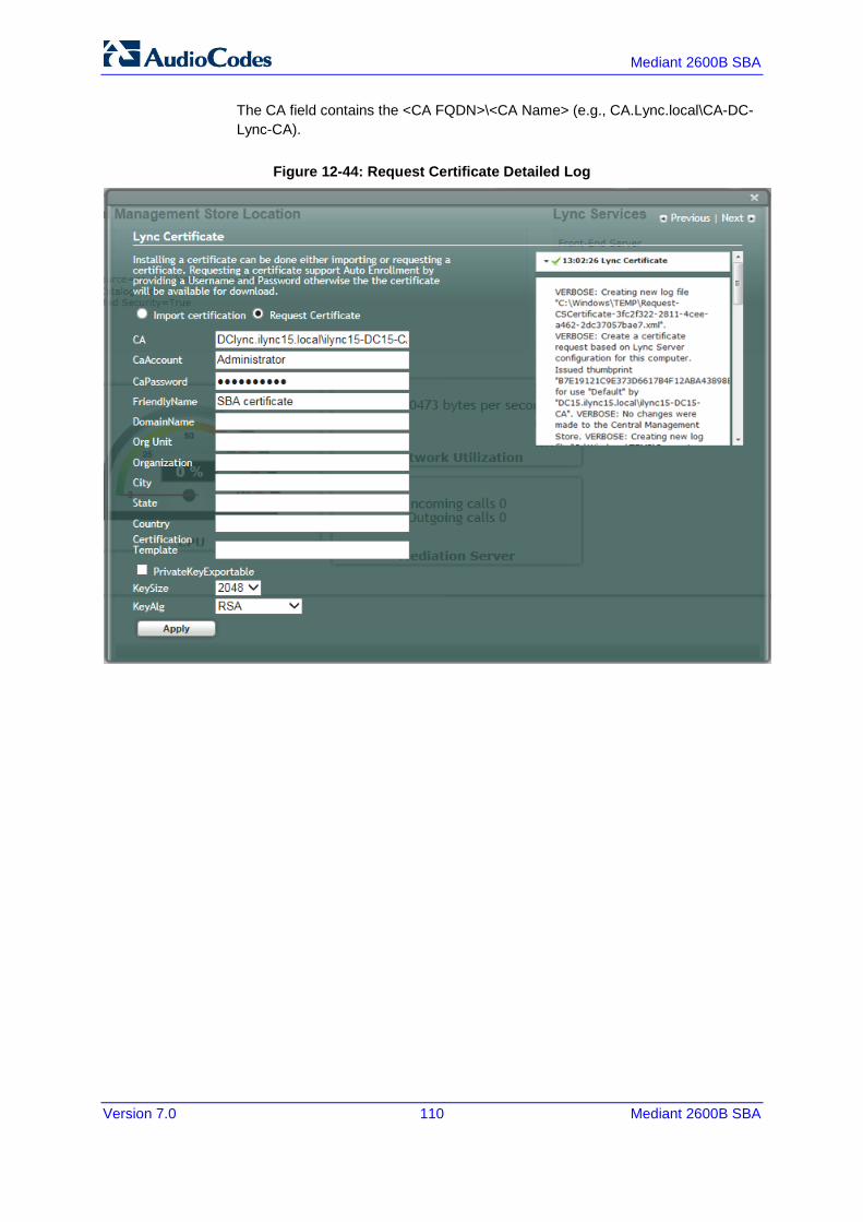
Mediant 2600B SBA
Version 7.0 110 Mediant 2600B SBA
The CA field contains the <CA FQDN>\<CA Name> (e.g., CA.Lync.local\CA-DC-Lync-CA).
Figure 12-44: Request Certificate Detailed Log

Version 7.0 111 Skype for Business
Installation & Maintenance Manual 12. Installing and Configuring the SBA
3. If the CA field is not entered, the system creates an enrollment certificate, which can be downloaded.
Figure 12-45: Lync Certificate SBA Certificate

Mediant 2600B SBA
Version 7.0 112 Mediant 2600B SBA
4. Click Apply; the following screen appears.
Figure 12-46: Lync Certificate – Download Enrolled Certificate01

Version 7.0 113 Skype for Business
Installation & Maintenance Manual 12. Installing and Configuring the SBA
5. Click the Download Enrolled Certificate link; the following screen appears.
6. Click Save. 7. Once the Enrollment Certificate has been signed, select the Import Certification
radio button as shown below and upload the signed certificate to be uploaded by using the Browse and File to Upload fields.
Figure 12-47: Lync Certificate – File Upload
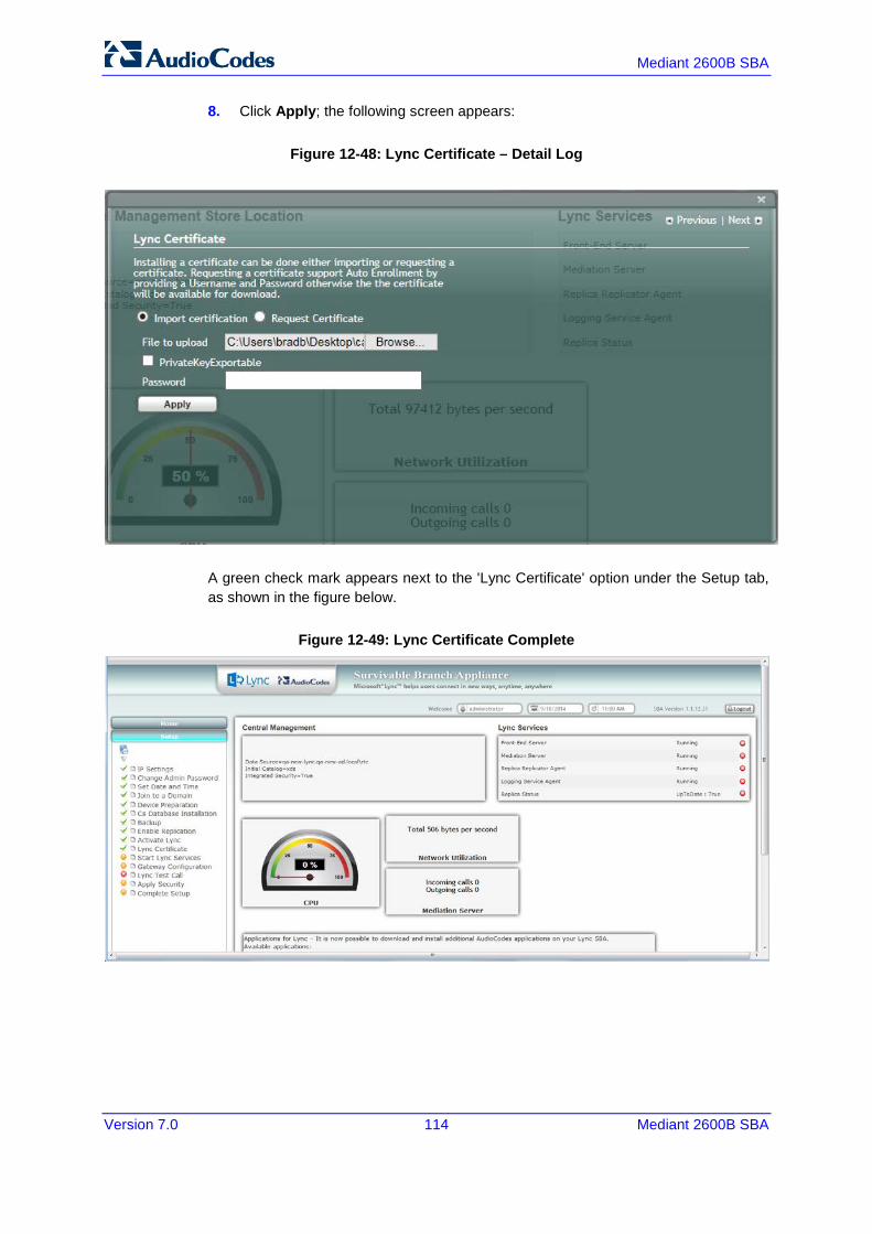
Mediant 2600B SBA
Version 7.0 114 Mediant 2600B SBA
8. Click Apply; the following screen appears:
Figure 12-48: Lync Certificate – Detail Log
A green check mark appears next to the 'Lync Certificate' option under the Setup tab, as shown in the figure below.
Figure 12-49: Lync Certificate Complete
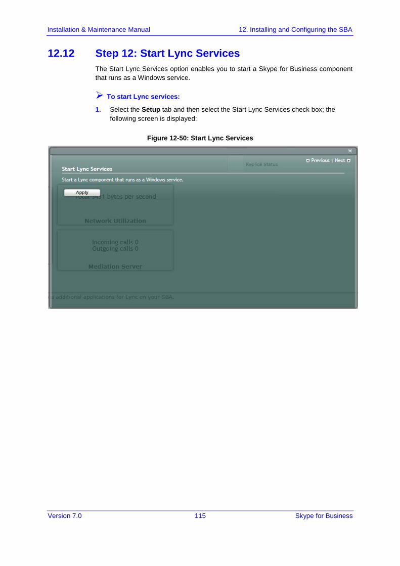
Version 7.0 115 Skype for Business
Installation & Maintenance Manual 12. Installing and Configuring the SBA
12.12 Step 12: Start Lync Services The Start Lync Services option enables you to start a Skype for Business component that runs as a Windows service.
To start Lync services:
1. Select the Setup tab and then select the Start Lync Services check box; the following screen is displayed:
Figure 12-50: Start Lync Services
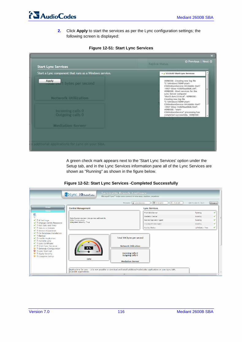
Mediant 2600B SBA
Version 7.0 116 Mediant 2600B SBA
2. Click Apply to start the services as per the Lync configuration settings; the following screen is displayed:
Figure 12-51: Start Lync Services
A green check mark appears next to the 'Start Lync Services' option under the Setup tab, and in the Lync Services information pane all of the Lync Services are shown as "Running" as shown in the figure below.
Figure 12-52: Start Lync Services -Completed Successfully
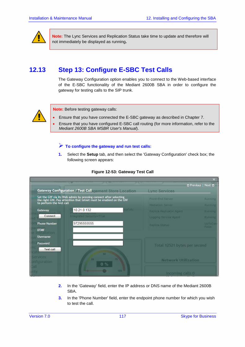
Version 7.0 117 Skype for Business
Installation & Maintenance Manual 12. Installing and Configuring the SBA
Note: The Lync Services and Replication Status take time to update and therefore will not immediately be displayed as running.
12.13 Step 13: Configure E-SBC Test Calls The Gateway Configuration option enables you to connect to the Web-based interface of the E-SBC functionality of the Mediant 2600B SBA in order to configure the gateway for testing calls to the SIP trunk.
Note: Before testing gateway calls:
• Ensure that you have connected the E-SBC gateway as described in Chapter 7. • Ensure that you have configured E-SBC call routing (for more information, refer to the
Mediant 2600B SBA MSBR User's Manual).
To configure the gateway and run test calls:
1. Select the Setup tab, and then select the 'Gateway Configuration' check box; the following screen appears:
Figure 12-53: Gateway Test Call
2. In the ‘Gateway’ field, enter the IP address or DNS name of the Mediant 2600B SBA.
3. In the 'Phone Number' field, enter the endpoint phone number for which you wish to test the call.
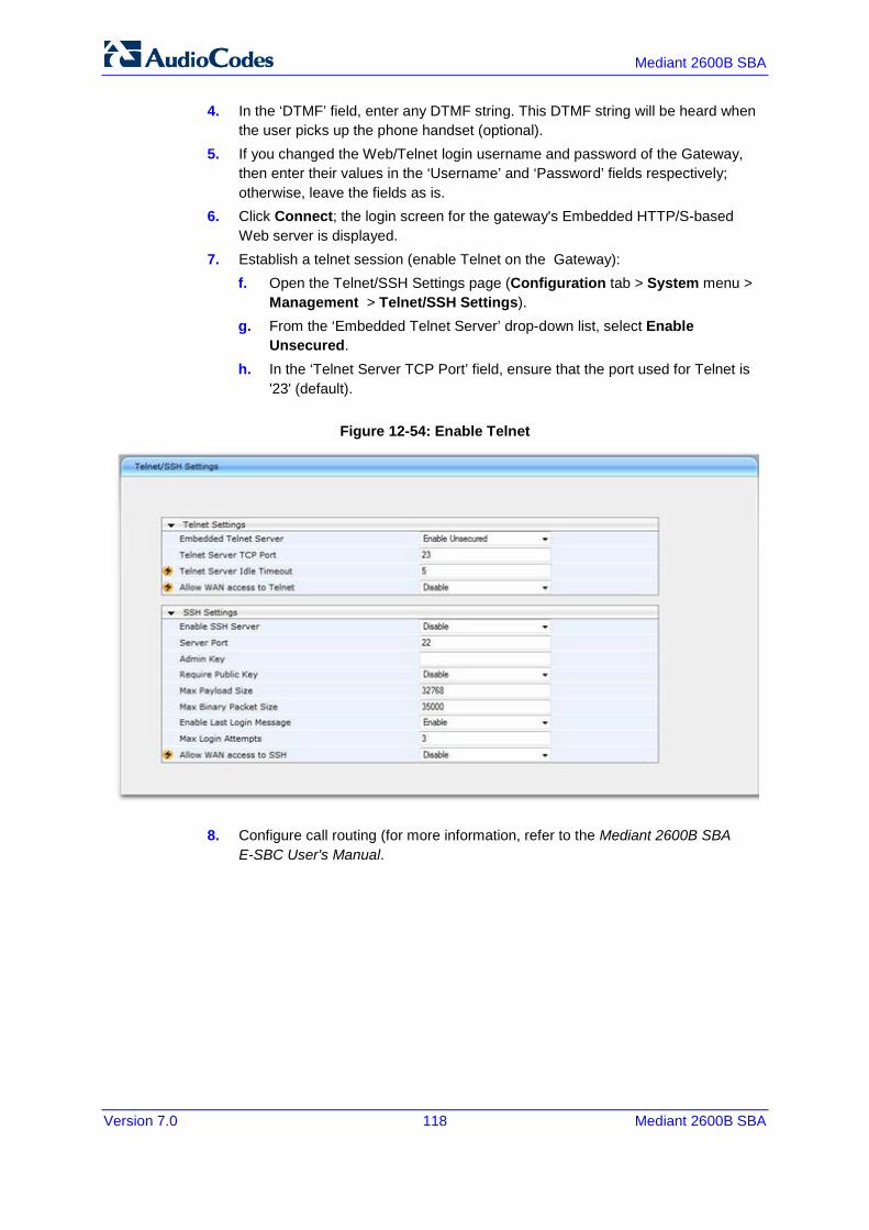
Mediant 2600B SBA
Version 7.0 118 Mediant 2600B SBA
4. In the ‘DTMF’ field, enter any DTMF string. This DTMF string will be heard when the user picks up the phone handset (optional).
5. If you changed the Web/Telnet login username and password of the Gateway, then enter their values in the ‘Username’ and ‘Password’ fields respectively; otherwise, leave the fields as is.
6. Click Connect; the login screen for the gateway's Embedded HTTP/S-based Web server is displayed.
7. Establish a telnet session (enable Telnet on the Gateway): f. Open the Telnet/SSH Settings page (Configuration tab > System menu >
Management > Telnet/SSH Settings). g. From the ‘Embedded Telnet Server’ drop-down list, select Enable
Unsecured. h. In the ‘Telnet Server TCP Port’ field, ensure that the port used for Telnet is
'23' (default).
Figure 12-54: Enable Telnet
8. Configure call routing (for more information, refer to the Mediant 2600B SBA E-SBC User's Manual.
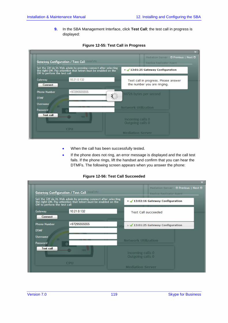
Version 7.0 119 Skype for Business
Installation & Maintenance Manual 12. Installing and Configuring the SBA
9. In the SBA Management Interface, click Test Call; the test call in progress is displayed:
Figure 12-55: Test Call in Progress
• When the call has been successfully tested.
• If the phone does not ring, an error message is displayed and the call test fails. If the phone rings, lift the handset and confirm that you can hear the DTMFs. The following screen appears when you answer the phone:
Figure 12-56: Test Call Succeeded
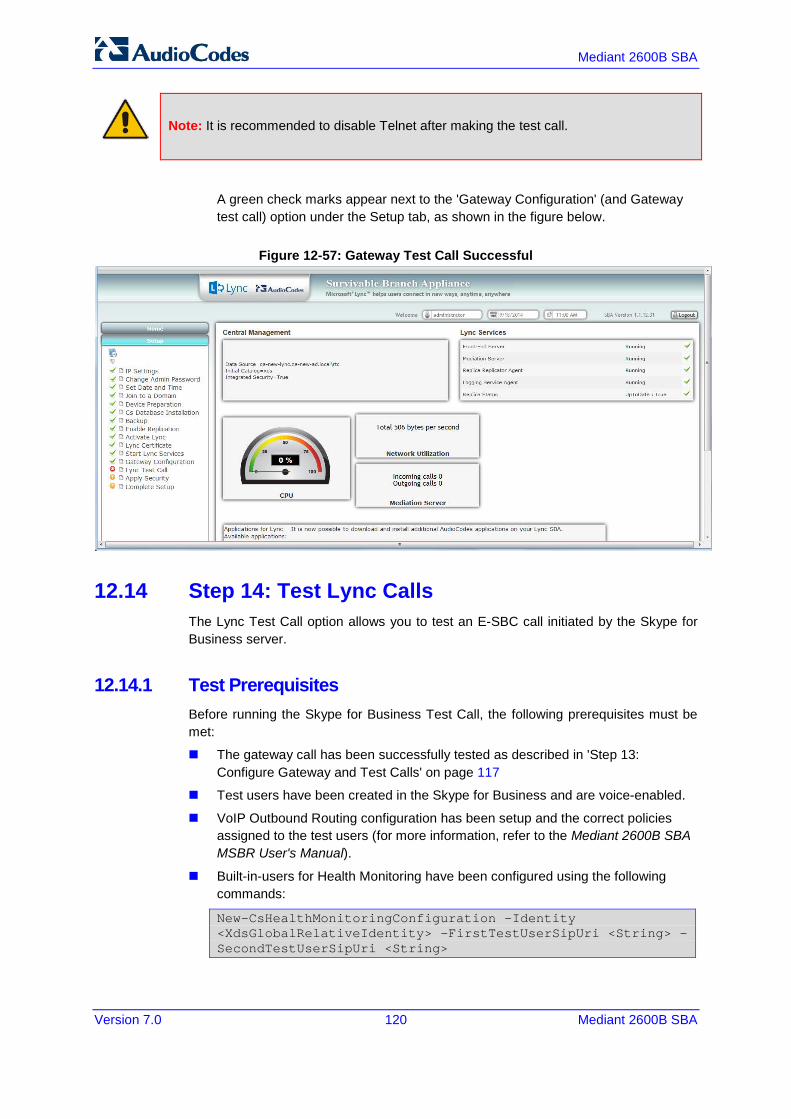
Mediant 2600B SBA
Version 7.0 120 Mediant 2600B SBA
Note: It is recommended to disable Telnet after making the test call.
A green check marks appear next to the 'Gateway Configuration' (and Gateway test call) option under the Setup tab, as shown in the figure below.
Figure 12-57: Gateway Test Call Successful
12.14 Step 14: Test Lync Calls The Lync Test Call option allows you to test an E-SBC call initiated by the Skype for Business server.
12.14.1 Test Prerequisites Before running the Skype for Business Test Call, the following prerequisites must be met:
The gateway call has been successfully tested as described in 'Step 13: Configure Gateway and Test Calls' on page 117
Test users have been created in the Skype for Business and are voice-enabled.
VoIP Outbound Routing configuration has been setup and the correct policies assigned to the test users (for more information, refer to the Mediant 2600B SBA MSBR User's Manual).
Built-in-users for Health Monitoring have been configured using the following commands:
New-CsHealthMonitoringConfiguration -Identity <XdsGlobalRelativeIdentity> -FirstTestUserSipUri <String> -SecondTestUserSipUri <String>
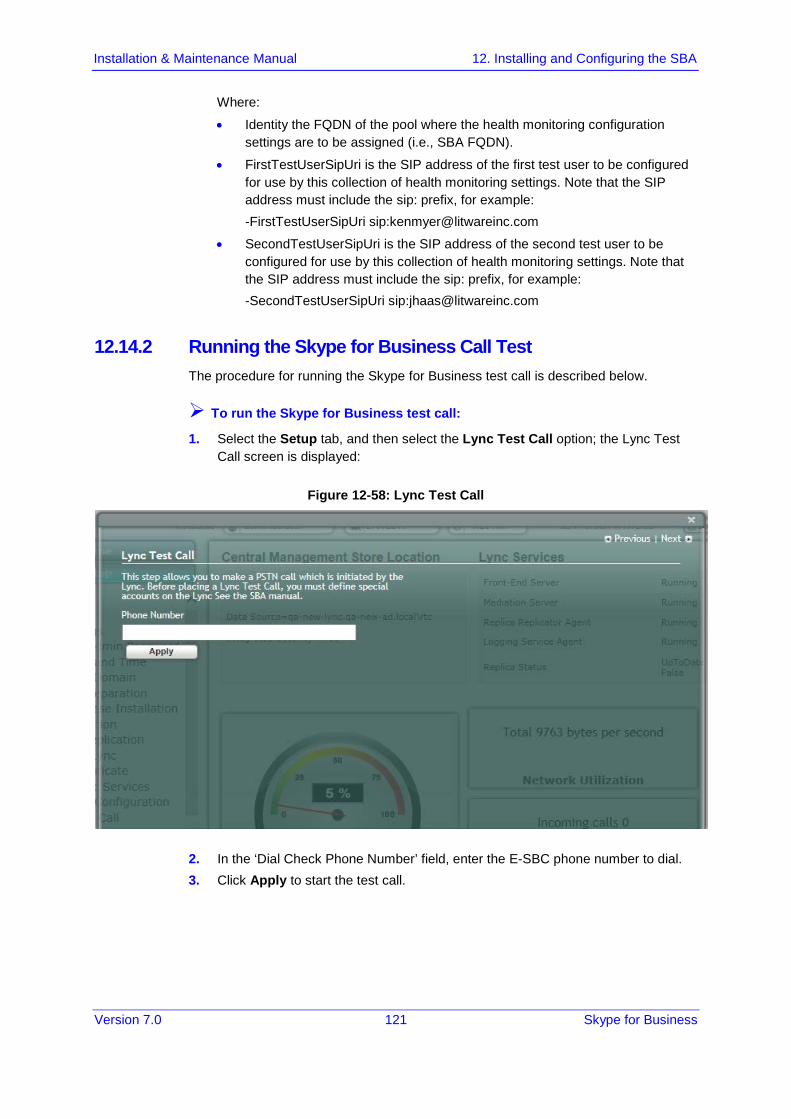
Version 7.0 121 Skype for Business
Installation & Maintenance Manual 12. Installing and Configuring the SBA
Where:
• Identity the FQDN of the pool where the health monitoring configuration settings are to be assigned (i.e., SBA FQDN).
• FirstTestUserSipUri is the SIP address of the first test user to be configured for use by this collection of health monitoring settings. Note that the SIP address must include the sip: prefix, for example: -FirstTestUserSipUri sip:[email protected]
• SecondTestUserSipUri is the SIP address of the second test user to be configured for use by this collection of health monitoring settings. Note that the SIP address must include the sip: prefix, for example: -SecondTestUserSipUri sip:[email protected]
12.14.2 Running the Skype for Business Call Test The procedure for running the Skype for Business test call is described below.
To run the Skype for Business test call:
1. Select the Setup tab, and then select the Lync Test Call option; the Lync Test Call screen is displayed:
Figure 12-58: Lync Test Call
2. In the ‘Dial Check Phone Number’ field, enter the E-SBC phone number to dial. 3. Click Apply to start the test call.

Mediant 2600B SBA
Version 7.0 122 Mediant 2600B SBA
If the test is successful, the phone of the E-SBC user rings and when the handset is lifted, the DTMF tones are heard. If the phone does not ring, an error message is displayed on the screen. The screen displays logged details of the call:
Figure 12-59: Lync Test Call – Logged Call Test Result
A green check mark appears next to the 'Lync Test Call' option under the Setup tab, as shown in the figure below.
Figure 12-60: Lync Test Call Successful
Version 7.0 123 Skype for Business
Installation & Maintenance Manual 12. Installing and Configuring the SBA
12.15 Step 15: Apply Security You can apply a security template to the device. This template configures the security for various SBA services. For example, firewall policy, registeries and OS audit policy. You can apply one of the following security policies:
No Policy-use a default hardening setup (no security template is loaded to the SBA device) as was the case until this release.
Use default template-Load an AudioCodes built default security template to the SBA device.
Upload a security template-Load an administrator-defined template to the SBA device.
Note: Once a template is loaded, you cannot perform rollback using the SBA GUI. To rollback the security settings, refer to the Microsoft document at:
http://technet.microsoft.com/en-us/library/cc733088.aspx http://technet.microsoft.com/en-us/library/cc733088.aspx
12.15.1 Apply No Policy This procedure describes how to configure the 'No Policy' security option on the SBA device. When this option is configured, a default hardening setup is implemented and no security template is loaded to the SBA device.
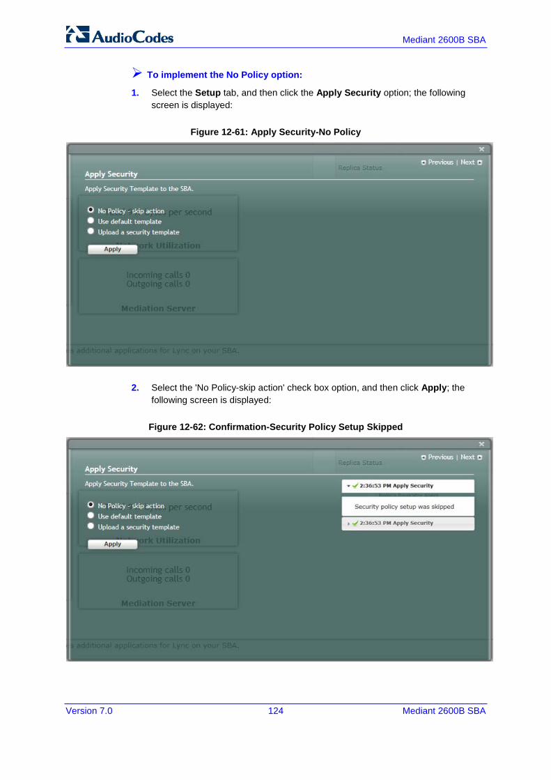
Mediant 2600B SBA
Version 7.0 124 Mediant 2600B SBA
To implement the No Policy option:
1. Select the Setup tab, and then click the Apply Security option; the following screen is displayed:
Figure 12-61: Apply Security-No Policy
2. Select the 'No Policy-skip action' check box option, and then click Apply; the following screen is displayed:
Figure 12-62: Confirmation-Security Policy Setup Skipped

Version 7.0 125 Skype for Business
Installation & Maintenance Manual 12. Installing and Configuring the SBA
12.15.2 Apply Default Security Template This procedure describes how to apply the default security template.
To apply the default security template:
1. Select the Setup tab, and then click the Apply Security option; the following screen is displayed:
Figure 12-63: Apply Security Policy- Use Default Template

Mediant 2600B SBA
Version 7.0 126 Mediant 2600B SBA
2. Select the 'Use default template' check box, and then click Apply; the SBA automatically logs out:
Figure 12-64: System Logout Default Security Applied
3. Click OK for the system to log out while running the security template;the following screen appears:
Figure 12-65: Security Setup is Complete
4. After a few minutes the security setup completes, and the SBA login screen appears.
5. Login and then select the Setup tab.
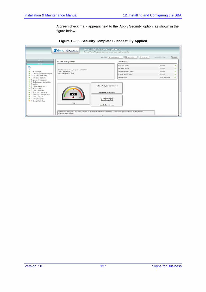
Version 7.0 127 Skype for Business
Installation & Maintenance Manual 12. Installing and Configuring the SBA
A green check mark appears next to the 'Apply Security' option, as shown in the figure below.
Figure 12-66: Security Template Successfully Applied
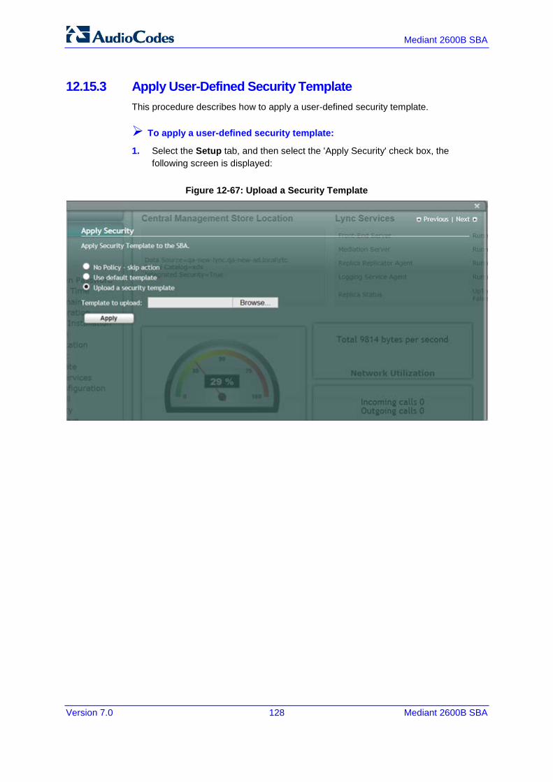
Mediant 2600B SBA
Version 7.0 128 Mediant 2600B SBA
12.15.3 Apply User-Defined Security Template This procedure describes how to apply a user-defined security template.
To apply a user-defined security template:
1. Select the Setup tab, and then select the 'Apply Security' check box, the following screen is displayed:
Figure 12-67: Upload a Security Template

Version 7.0 129 Skype for Business
Installation & Maintenance Manual 12. Installing and Configuring the SBA
2. Select the 'Upload a security template' check box; the following screen appears:
Figure 12-68: Apply Security Policy- Browse to Security Template
3. Browse to a custom security template to upload and run, and then click Apply; the SBA automatically logs out:
Figure 12-69: Security Template Automatic System Logout
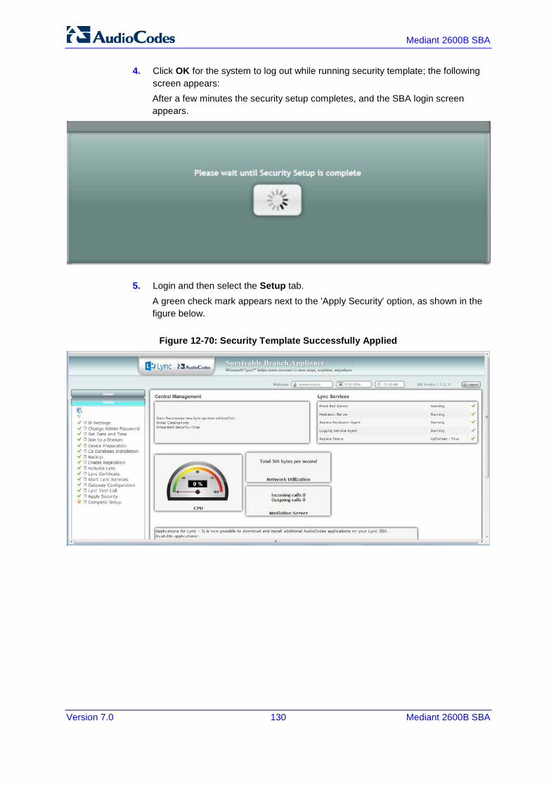
Mediant 2600B SBA
Version 7.0 130 Mediant 2600B SBA
4. Click OK for the system to log out while running security template; the following screen appears: After a few minutes the security setup completes, and the SBA login screen appears.
5. Login and then select the Setup tab. A green check mark appears next to the 'Apply Security' option, as shown in the figure below.
Figure 12-70: Security Template Successfully Applied

Version 7.0 131 Skype for Business
Installation & Maintenance Manual 12. Installing and Configuring the SBA
12.16 Step 16: (Optional) Remote Control This section describes how to enable or disable the RDP (Remote Desktop Protocol) and the Remote Windows Powershell on the SBA device. Remote Power Shell - The Remote PowerShell is by default enabled. Note that for previous versions (prior to version 1.1.12.0), the Remote PowerShell was by default disabled, and could only be enabled by configuring the parameter 'PSRemoting = Force' in the PowerShell. RDP (Remote Desktop Protocol): The RDP is enabled by default for all SBA versions.
Note: If you are using the SBA Pro to upgrade the SBA, then you must enable the Remote Windows Powershell.
To enable/disable remote controls:
1. Select the Tools tab, and then select the 'Remote Control' checkbox. The Remote Control screen is displayed:
Figure 12-71: Remote Control
2. Select the 'Enable Remote Desktop' check box to enable the Remote Desktop on the SBA.
3. Select the 'Enable Remote Powershell' check box to enable the Remote Powershell on the SBA.
4. Click Apply.
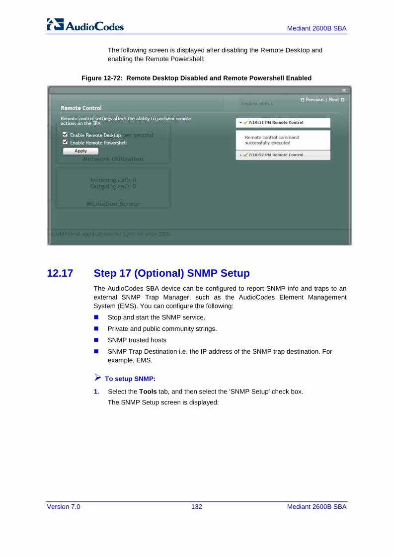
Mediant 2600B SBA
Version 7.0 132 Mediant 2600B SBA
The following screen is displayed after disabling the Remote Desktop and enabling the Remote Powershell:
Figure 12-72: Remote Desktop Disabled and Remote Powershell Enabled
12.17 Step 17 (Optional) SNMP Setup The AudioCodes SBA device can be configured to report SNMP info and traps to an external SNMP Trap Manager, such as the AudioCodes Element Management System (EMS). You can configure the following:
Stop and start the SNMP service.
Private and public community strings.
SNMP trusted hosts
SNMP Trap Destination i.e. the IP address of the SNMP trap destination. For example, EMS.
To setup SNMP:
1. Select the Tools tab, and then select the 'SNMP Setup' check box. The SNMP Setup screen is displayed:

Version 7.0 133 Skype for Business
Installation & Maintenance Manual 12. Installing and Configuring the SBA
Figure 12-73: SNMP Setup Screen
If the SNMP Service is running, an adjacent green sign is indicated. 2. In the SNMP Manager Communities pane, configure the public and private
community strings. 3. If you wish to configure trusted hosts, select the 'From the Following Hosts Only'
check box, and then in the 'SNMP Trusted Hosts' field, enter the names of the SNMP Trusted Hosts.
4. In the 'Trap Community Name' field, enter the name of the SNMPv2 community (user) name.
5. In the 'SNMP Trap Destination' field, enter the IP address of the destination trap manager e.g. EMS. You can enter up to five SNMP trap destinations.
6. Click Apply.
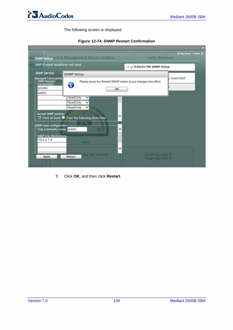
Mediant 2600B SBA
Version 7.0 134 Mediant 2600B SBA
The following screen is displayed:
Figure 12-74: SNMP Restart Confirmation
7. Click OK, and then click Restart.

Version 7.0 135 Skype for Business
Installation & Maintenance Manual 12. Installing and Configuring the SBA
The following screen is displayed:
Figure 12-75: SNMP Setup After Restart

Mediant 2600B SBA
Version 7.0 136 Mediant 2600B SBA
If the SNMP service is stopped, the following screen is displayed:
Figure 12-76: SNMP Service Started
8. Click Start to start the SNMP service.
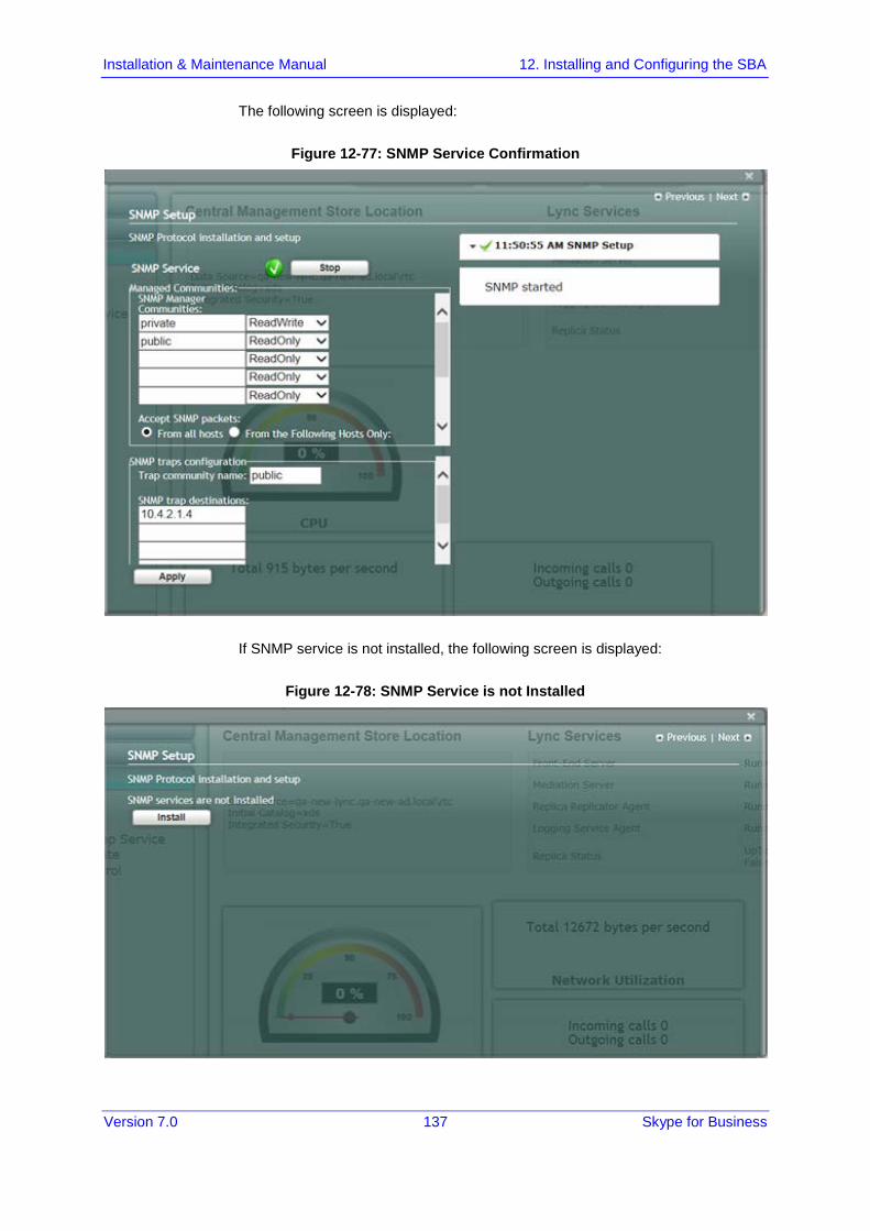
Version 7.0 137 Skype for Business
Installation & Maintenance Manual 12. Installing and Configuring the SBA
The following screen is displayed:
Figure 12-77: SNMP Service Confirmation
If SNMP service is not installed, the following screen is displayed:
Figure 12-78: SNMP Service is not Installed
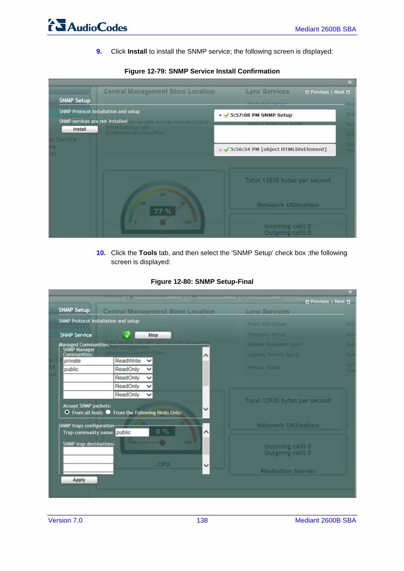
Mediant 2600B SBA
Version 7.0 138 Mediant 2600B SBA
9. Click Install to install the SNMP service; the following screen is displayed:
Figure 12-79: SNMP Service Install Confirmation
10. Click the Tools tab, and then select the 'SNMP Setup' check box ;the following screen is displayed:
Figure 12-80: SNMP Setup-Final

Version 7.0 139 Skype for Business
Installation & Maintenance Manual 12. Installing and Configuring the SBA
12.18 Step 18: Completing SBA Setup Once you have completed all configurations as described in the previous sections, you need to perform the procedure described below to complete the SBA setup.
To complete SBA setup:
1. Log in to the SBA Web wizard (if not logged in already). 2. Select the Setup tab, and then select the 'Complete Setup' checkbox; the
Complete Setup screen appears:
Figure 12-81: Complete SBA Setup Screen
3. Click Complete; the following screen appears, indicating that the SBA setup is complete:

Mediant 2600B SBA
Version 7.0 140 Mediant 2600B SBA
Figure 12-82: SBA Setup Complete Message
A green check mark appears next to the 'Complete Setup' option under the Setup tab, as shown in the figure below.
Figure 12-83: Complete Setup – Completed Successfully

Version 7.0 141 Skype for Business
Installation & Maintenance Manual 12. Installing and Configuring the SBA
12.19 Monitoring and Maintenance Actions This chapter describes how to connect to the SBA Management interface and
12.19.1 Viewing General SBA Status in the Home Page The general operating status of the SBA can be viewed in the Home page. This page displays the following:
Central management store location
SBA services status (stopped or running)
CPU and network usages
Number of incoming and outgoing calls
Figure 12-84: SBA Home Page
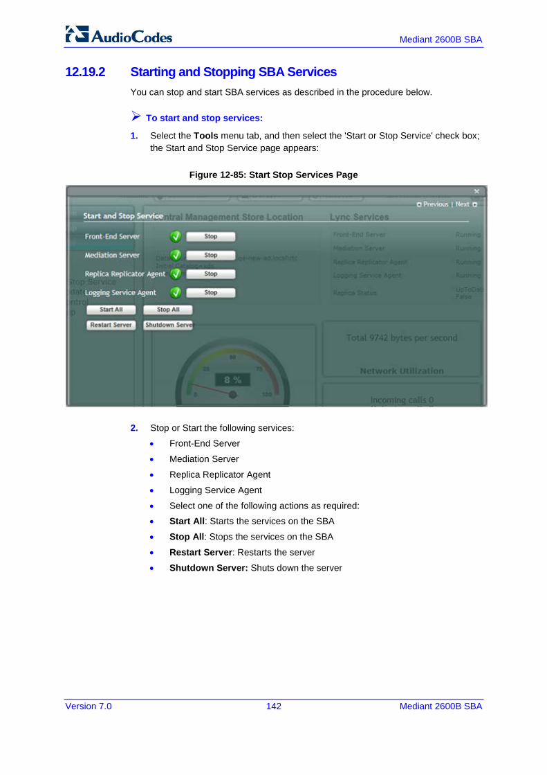
Mediant 2600B SBA
Version 7.0 142 Mediant 2600B SBA
12.19.2 Starting and Stopping SBA Services You can stop and start SBA services as described in the procedure below.
To start and stop services:
1. Select the Tools menu tab, and then select the 'Start or Stop Service' check box; the Start and Stop Service page appears:
Figure 12-85: Start Stop Services Page
2. Stop or Start the following services:
• Front-End Server
• Mediation Server
• Replica Replicator Agent
• Logging Service Agent
• Select one of the following actions as required:
• Start All: Starts the services on the SBA
• Stop All: Stops the services on the SBA
• Restart Server: Restarts the server
• Shutdown Server: Shuts down the server

Version 7.0 143 Skype for Business
Installation & Maintenance Manual 12. Installing and Configuring the SBA
12.19.3 Viewing Logged Events The procedure below describes how to view and handle logged events.
To view and handle logged events:
1. Select the Logs tab; the Logs screen appears displaying logged events:
Figure 12-86: Logs Screen Displaying Logged Events
2. To view details of a logged event, select the event.
Figure 12-87: Detailed Log Display
3. To clear the displayed log, click the Clear Logs button. To export the logged events, click the Export Logs.
Mediant 2600B SBA
Version 7.0 144 Mediant 2600B SBA
12.19.4 Logging Out The procedure below describes how to log out the SBA Management Interface.
To log out the SBA Web wizard:
Click the Logout button in the top right-hand corner of the screen.

Part V Configuring the E-SBC Device
This part describes how to configure the E-SBC device for E-SBC calls.

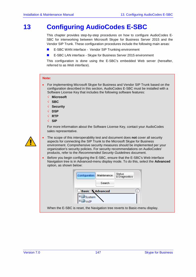
Installation & Maintenance Manual 13. Configuring AudioCodes E-SBC
Version 7.0 147 Skype for Business
13 Configuring AudioCodes E-SBC This chapter provides step-by-step procedures on how to configure AudioCodes E-SBC for interworking between Microsoft Skype for Business Server 2015 and the Vendor SIP Trunk. These configuration procedures include the following main areas:
E-SBC WAN interface - Vendor SIP Trunking environment
E-SBC LAN interface - Skype for Business Server 2015 environment
This configuration is done using the E-SBC's embedded Web server (hereafter, referred to as Web interface).
Note:
• For implementing Microsoft Skype for Business and Vendor SIP Trunk based on the configuration described in this section, AudioCodes E-SBC must be installed with a Software License Key that includes the following software features: √ Microsoft √ SBC √ Security √ DSP √ RTP √ SIP
For more information about the Software License Key, contact your AudioCodes sales representative.
• The scope of this interoperability test and document does not cover all security aspects for connecting the SIP Trunk to the Microsoft Skype for Business environment. Comprehensive security measures should be implemented per your organization's security policies. For security recommendations on AudioCodes’ products, refer to the Recommended Security Guidelines document.
• Before you begin configuring the E-SBC, ensure that the E-SBC's Web interface Navigation tree is in Advanced-menu display mode. To do this, select the Advanced option, as shown below:
When the E-SBC is reset, the Navigation tree reverts to Basic-menu display.
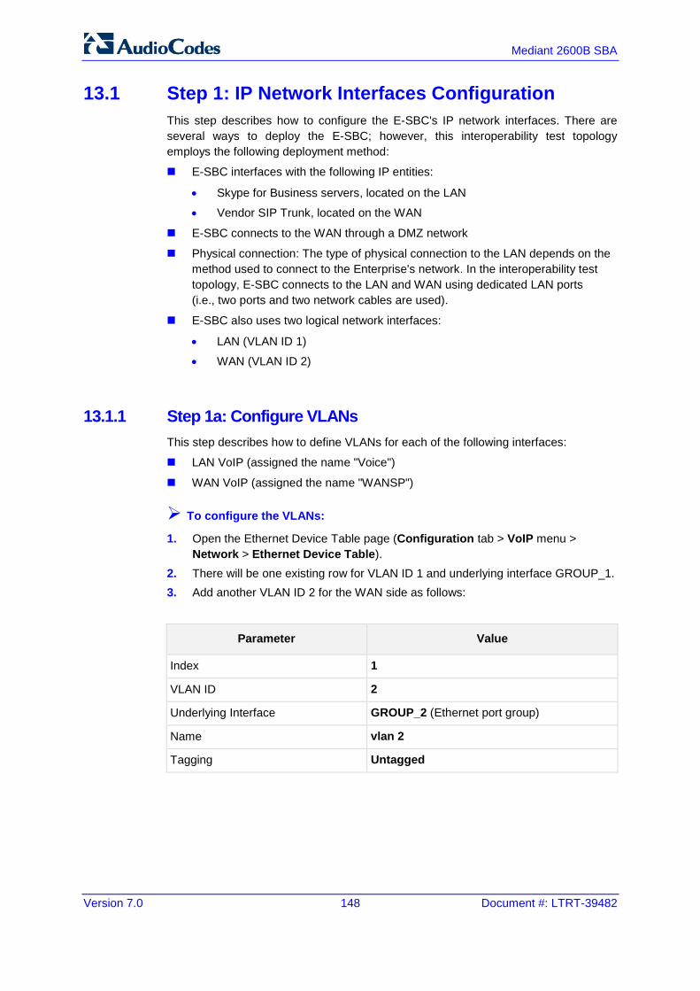
Version 7.0 148 Document #: LTRT-39482
Mediant 2600B SBA
13.1 Step 1: IP Network Interfaces Configuration This step describes how to configure the E-SBC's IP network interfaces. There are several ways to deploy the E-SBC; however, this interoperability test topology employs the following deployment method:
E-SBC interfaces with the following IP entities:
• Skype for Business servers, located on the LAN
• Vendor SIP Trunk, located on the WAN
E-SBC connects to the WAN through a DMZ network
Physical connection: The type of physical connection to the LAN depends on the method used to connect to the Enterprise's network. In the interoperability test topology, E-SBC connects to the LAN and WAN using dedicated LAN ports (i.e., two ports and two network cables are used).
E-SBC also uses two logical network interfaces:
• LAN (VLAN ID 1)
• WAN (VLAN ID 2)
13.1.1 Step 1a: Configure VLANs This step describes how to define VLANs for each of the following interfaces:
LAN VoIP (assigned the name "Voice")
WAN VoIP (assigned the name "WANSP")
To configure the VLANs:
1. Open the Ethernet Device Table page (Configuration tab > VoIP menu > Network > Ethernet Device Table).
2. There will be one existing row for VLAN ID 1 and underlying interface GROUP_1. 3. Add another VLAN ID 2 for the WAN side as follows:
Parameter Value
Index 1
VLAN ID 2
Underlying Interface GROUP_2 (Ethernet port group)
Name vlan 2
Tagging Untagged

Installation & Maintenance Manual 13. Configuring AudioCodes E-SBC
Version 7.0 149 Skype for Business
Figure 13-1: Configured VLAN IDs in Ethernet Device Table
13.1.2 Step 1b: Configure Network Interfaces This step describes how to configure the IP network interfaces for each of the following interfaces:
LAN VoIP (assigned the name "Voice")
WAN VoIP (assigned the name "WANSP")
To configure the IP network interfaces:
1. Open the IP Interfaces Table page (Configuration tab > VoIP menu > Network > IP Interfaces Table).
2. Modify the existing LAN network interface: a. Select the 'Index' radio button of the OAMP + Media + Control table row,
and then click Edit. b. Configure the interface as follows:
Parameter Value
IP Address 10.15.45.101 (IP address of E-SBC)
Prefix Length 16 (subnet mask in bits for 255.255.0.0)
Default Gateway 10.15.0.1
VLAN ID 1
Interface Name Voice (arbitrary descriptive name)
Primary DNS Server IP Address 10.15.25.1
Underlying Device vlan 1
3. Add a network interface for the WAN side: a. Enter 1, and then click Add Index. b. Configure the interface as follows:
Parameter Value
Application Type Media + Control
IP Address 195.189.192.156 (WAN IP address)

Version 7.0 150 Document #: LTRT-39482
Mediant 2600B SBA
Parameter Value
Prefix Length 25 (for 255.255.255.128)
Default Gateway 195.189.192.129 (router's IP address)
VLAN ID 2
Interface Name WANSP
Primary DNS Server IP Address 80.179.52.100
Secondary DNS Server IP Address 80.179.55.100
Underlying Device vlan 2
4. Click Apply, and then Done.
The configured IP network interfaces are shown below:
Figure 13-2: Configured Network Interfaces in IP Interfaces Table
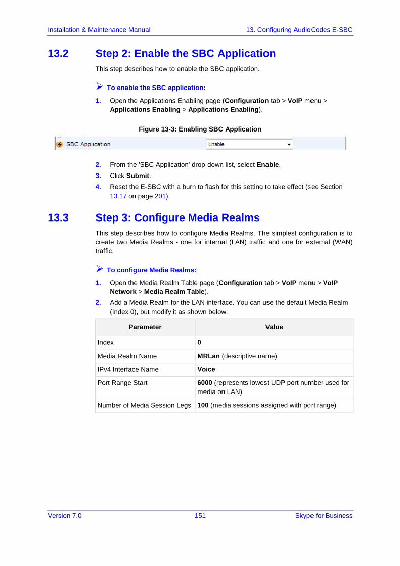
Installation & Maintenance Manual 13. Configuring AudioCodes E-SBC
Version 7.0 151 Skype for Business
13.2 Step 2: Enable the SBC Application This step describes how to enable the SBC application.
To enable the SBC application:
1. Open the Applications Enabling page (Configuration tab > VoIP menu > Applications Enabling > Applications Enabling).
Figure 13-3: Enabling SBC Application
2. From the 'SBC Application' drop-down list, select Enable. 3. Click Submit. 4. Reset the E-SBC with a burn to flash for this setting to take effect (see Section
13.17 on page 201).
13.3 Step 3: Configure Media Realms This step describes how to configure Media Realms. The simplest configuration is to create two Media Realms - one for internal (LAN) traffic and one for external (WAN) traffic.
To configure Media Realms:
1. Open the Media Realm Table page (Configuration tab > VoIP menu > VoIP Network > Media Realm Table).
2. Add a Media Realm for the LAN interface. You can use the default Media Realm (Index 0), but modify it as shown below:
Parameter Value
Index 0
Media Realm Name MRLan (descriptive name)
IPv4 Interface Name Voice
Port Range Start 6000 (represents lowest UDP port number used for media on LAN)
Number of Media Session Legs 100 (media sessions assigned with port range)

Version 7.0 152 Document #: LTRT-39482
Mediant 2600B SBA
Figure 13-4: Configuring Media Realm for LAN
3. Configure a Media Realm for WAN traffic:
Parameter Value
Index 1
Media Realm Name MRWan (arbitrary name)
IPv4 Interface Name WANSP
Port Range Start 7000 (represents lowest UDP port number used for media on WAN)
Number of Media Session Legs 100 (media sessions assigned with port range)
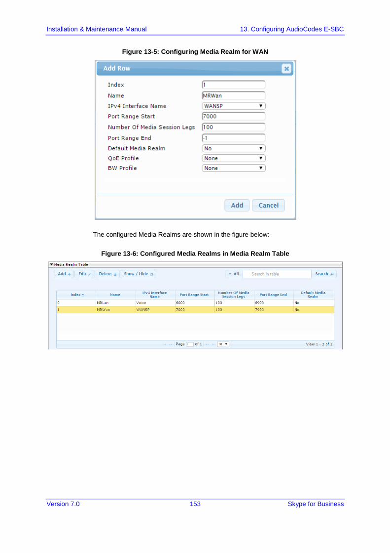
Installation & Maintenance Manual 13. Configuring AudioCodes E-SBC
Version 7.0 153 Skype for Business
Figure 13-5: Configuring Media Realm for WAN
The configured Media Realms are shown in the figure below:
Figure 13-6: Configured Media Realms in Media Realm Table

Version 7.0 154 Document #: LTRT-39482
Mediant 2600B SBA
13.4 Step 4: Configure SIP Signaling Interfaces This step describes how to configure SIP Interfaces. For the interoperability test topology, an internal and external SIP Interface must be configured for the E-SBC.
To configure SIP Interfaces:
1. Open the SIP Interface Table page (Configuration tab > VoIP menu > VoIP Network > SIP Interface Table).
2. Add a SIP Interface for the LAN interface. You can use the default SIP Interface (Index 0), but modify it as shown below:
Parameter Value
Index 0
Interface Name S4B (see Note at the end of this section)
Network Interface Voice
Application Type SBC
TLS Port 5067 (see Note below)
TCP and UDP 0
Media Realm MRLan
Note: The TLS port parameter must be identically configured in the Skype for Business Topology Builder (see Chapter 10 on page 9).
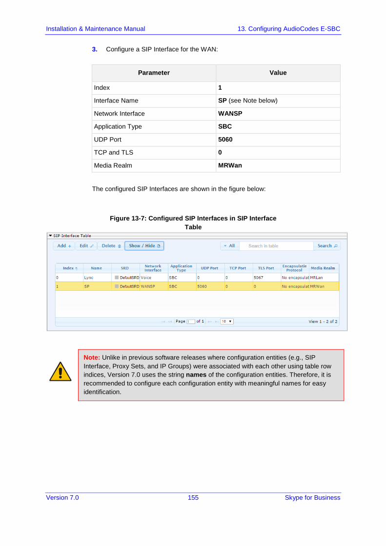
Installation & Maintenance Manual 13. Configuring AudioCodes E-SBC
Version 7.0 155 Skype for Business
3. Configure a SIP Interface for the WAN:
Parameter Value
Index 1
Interface Name SP (see Note below)
Network Interface WANSP
Application Type SBC
UDP Port 5060
TCP and TLS 0
Media Realm MRWan
The configured SIP Interfaces are shown in the figure below:
Figure 13-7: Configured SIP Interfaces in SIP Interface Table
Note: Unlike in previous software releases where configuration entities (e.g., SIP Interface, Proxy Sets, and IP Groups) were associated with each other using table row indices, Version 7.0 uses the string names of the configuration entities. Therefore, it is recommended to configure each configuration entity with meaningful names for easy identification.
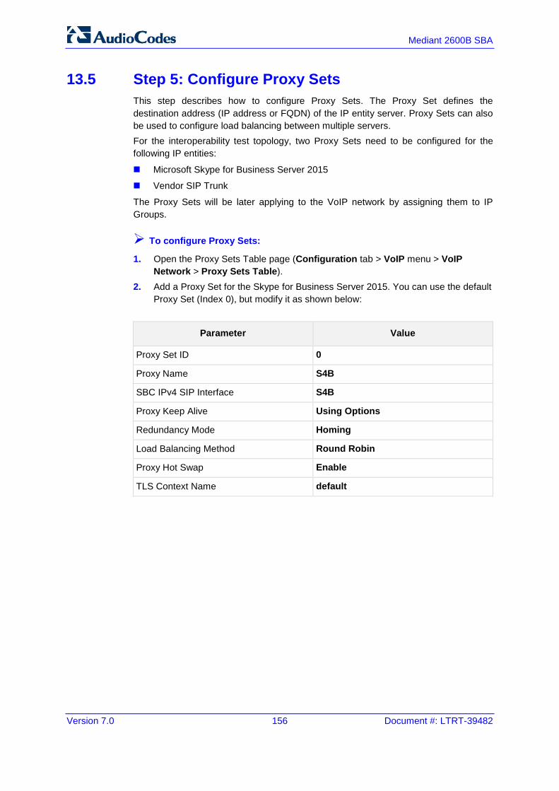
Version 7.0 156 Document #: LTRT-39482
Mediant 2600B SBA
13.5 Step 5: Configure Proxy Sets This step describes how to configure Proxy Sets. The Proxy Set defines the destination address (IP address or FQDN) of the IP entity server. Proxy Sets can also be used to configure load balancing between multiple servers. For the interoperability test topology, two Proxy Sets need to be configured for the following IP entities:
Microsoft Skype for Business Server 2015
Vendor SIP Trunk
The Proxy Sets will be later applying to the VoIP network by assigning them to IP Groups.
To configure Proxy Sets:
1. Open the Proxy Sets Table page (Configuration tab > VoIP menu > VoIP Network > Proxy Sets Table).
2. Add a Proxy Set for the Skype for Business Server 2015. You can use the default Proxy Set (Index 0), but modify it as shown below:
Parameter Value
Proxy Set ID 0
Proxy Name S4B
SBC IPv4 SIP Interface S4B
Proxy Keep Alive Using Options
Redundancy Mode Homing
Load Balancing Method Round Robin
Proxy Hot Swap Enable
TLS Context Name default

Installation & Maintenance Manual 13. Configuring AudioCodes E-SBC
Version 7.0 157 Skype for Business
Figure 13-8: Configuring Proxy Set for Microsoft Skype for Business Server 2015
3. Configure a Proxy Address Table for Proxy Set for Skype for Business Server 2015: a. Go to Configuration tab > VoIP menu > VoIP Network > Proxy Sets Table
> Proxy Address Table.
Parameter Value
Index 0
Proxy Address SBA15.iSFB.15.local:5067
Transport Type TLS
Note: The Proxy Address FQDN must be identically configured in the Skype for Business Topology Builder (see 10.1 on page 45).

Version 7.0 158 Document #: LTRT-39482
Mediant 2600B SBA
Figure 13-9: Configuring Proxy Address for Microsoft Skype for Business Server 2015
4. Configure a Proxy Set for the Vendor SIP Trunk:
Parameter Value
Proxy Set ID 1
Proxy Name SP
SBC IPv4 SIP Interface SP
Proxy Keep Alive Using Options
Figure 13-10: Configuring Proxy Set for Vendor SIP Trunk

Installation & Maintenance Manual 13. Configuring AudioCodes E-SBC
Version 7.0 159 Skype for Business
a. Configure a Proxy Address Table for Proxy Set 1: b. Go to Configuration tab > VoIP menu > VoIP Network > Proxy Sets Table
> Proxy Address Table.
Parameter Value
Index 0
Proxy Address Vendor.com:5060 ( IP address / FQDN and destination port)
Transport Type UDP
Figure 13-11: Configuring Proxy Address for Vendor SIP Trunk
The configured Proxy Sets are shown in the figure below:
Figure 13-12: Configured Proxy Sets in Proxy Sets Table
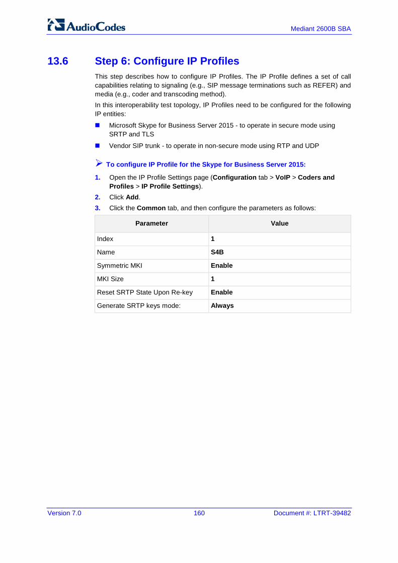
Version 7.0 160 Document #: LTRT-39482
Mediant 2600B SBA
13.6 Step 6: Configure IP Profiles This step describes how to configure IP Profiles. The IP Profile defines a set of call capabilities relating to signaling (e.g., SIP message terminations such as REFER) and media (e.g., coder and transcoding method). In this interoperability test topology, IP Profiles need to be configured for the following IP entities:
Microsoft Skype for Business Server 2015 - to operate in secure mode using SRTP and TLS
Vendor SIP trunk - to operate in non-secure mode using RTP and UDP
To configure IP Profile for the Skype for Business Server 2015:
1. Open the IP Profile Settings page (Configuration tab > VoIP > Coders and Profiles > IP Profile Settings).
2. Click Add. 3. Click the Common tab, and then configure the parameters as follows:
Parameter Value
Index 1
Name S4B
Symmetric MKI Enable
MKI Size 1
Reset SRTP State Upon Re-key Enable
Generate SRTP keys mode: Always

Installation & Maintenance Manual 13. Configuring AudioCodes E-SBC
Version 7.0 161 Skype for Business
Figure 13-13: Configuring IP Profile for Skype for Business Server 2015 – Common Tab
4. Click the SBC Signaling tab, and then configure the parameters as follows:
Parameter Value
Remote Update Support Supported Only After Connect
Remote re-INVITE Support Supported Only With SDP
Remote Delayed Offer Support Not Supported
Remote REFER Mode Handle Locally (required, as Skype for Business Server 2015 does not support receipt of SIP REFER)
Remote 3xx Mode Handle Locally (required, as Skype for Business Server 2015 does not support receipt of SIP 3xx responses)
Remote Early Media RTP Detection Behavior
By Media (required, as Skype for Business Server 2015 does not send RTP immediately to remote side when it sends a SIP 18x response)
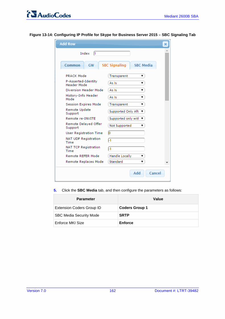
Version 7.0 162 Document #: LTRT-39482
Mediant 2600B SBA
Figure 13-14: Configuring IP Profile for Skype for Business Server 2015 – SBC Signaling Tab
5. Click the SBC Media tab, and then configure the parameters as follows:
Parameter Value
Extension Coders Group ID Coders Group 1
SBC Media Security Mode SRTP
Enforce MKI Size Enforce

Installation & Maintenance Manual 13. Configuring AudioCodes E-SBC
Version 7.0 163 Skype for Business
Figure 13-15: Configuring IP Profile for Skype for Business Server 2015 – SBC Media Tab
To configure an IP Profile for the Vendor SIP Trunk:
1. Click Add. 2. Click the Common tab, and then configure the parameters as follows:
Parameter Value
Index 2
Profile Name SP

Version 7.0 164 Document #: LTRT-39482
Mediant 2600B SBA
Figure 13-16: Configuring IP Profile for Vendor SIP Trunk – Common Tab
3. Click the SBC Signaling tab, and then configure the parameters as follows:
Parameter Value
P-Asserted-Identity Header Mode Add (required for anonymous calls)
Remote REFER Behavior Handle Locally (E-SBC handles / terminates incoming REFER requests instead of forwarding them to SIP Trunk)
Remote Can Play Ringback No (required, as Skype for Business Server 2015 does not provide a ringback tone for incoming calls)

Installation & Maintenance Manual 13. Configuring AudioCodes E-SBC
Version 7.0 165 Skype for Business
Figure 13-17: Configuring IP Profile for Vendor SIP Trunk – SBC Signaling Tab
4. Click the SBC Media tab, and then configure the parameters as follows:
Parameter Value
Extension Coders Group ID Coders Group 2
Allowed Coders Group ID Coders Group 2
Allowed Coders Mode Preference (lists Allowed Coders first and then original coders in received SDP offer)
Media Security Behavior RTP

Version 7.0 166 Document #: LTRT-39482
Mediant 2600B SBA
Figure 13-18: Configuring IP Profile for Vendor SIP Trunk – SBC Media Tab
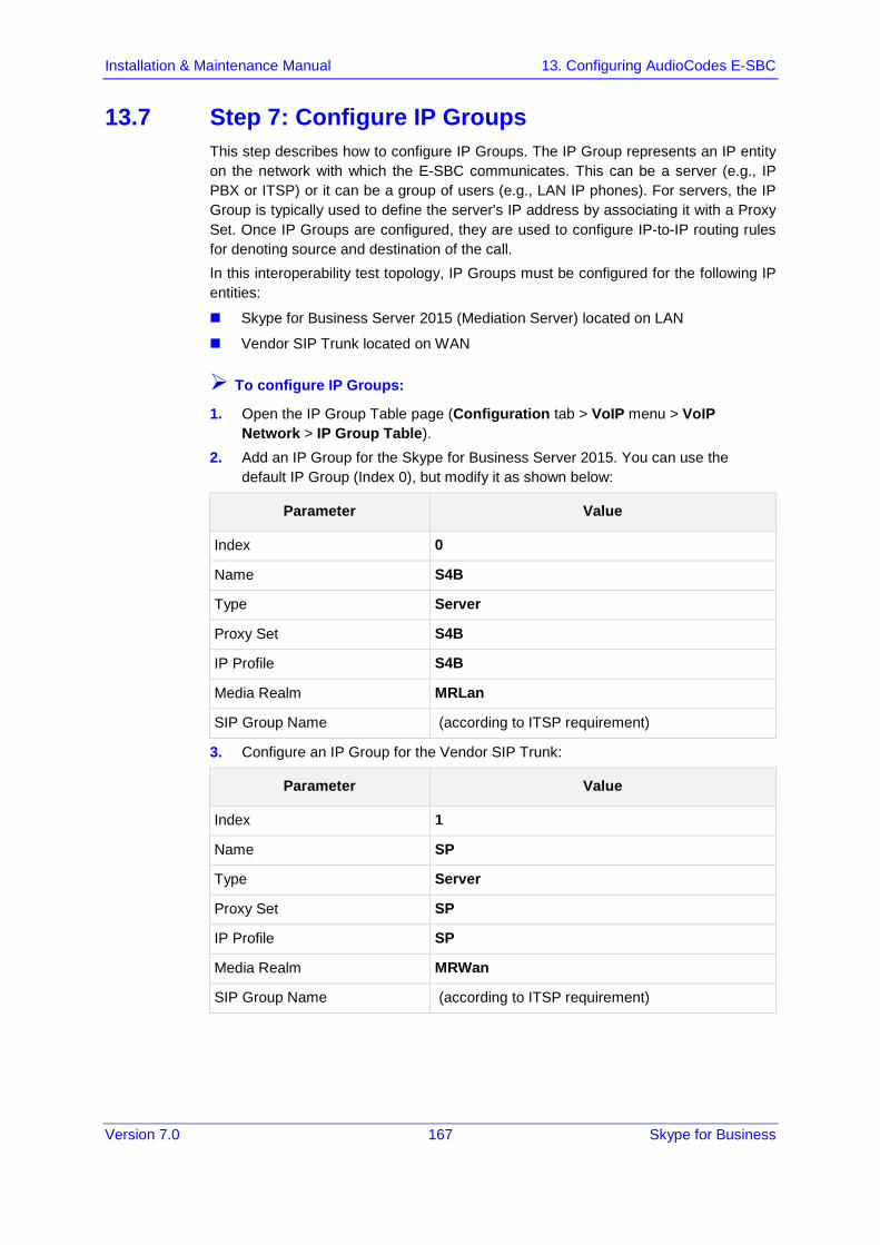
Installation & Maintenance Manual 13. Configuring AudioCodes E-SBC
Version 7.0 167 Skype for Business
13.7 Step 7: Configure IP Groups This step describes how to configure IP Groups. The IP Group represents an IP entity on the network with which the E-SBC communicates. This can be a server (e.g., IP PBX or ITSP) or it can be a group of users (e.g., LAN IP phones). For servers, the IP Group is typically used to define the server's IP address by associating it with a Proxy Set. Once IP Groups are configured, they are used to configure IP-to-IP routing rules for denoting source and destination of the call. In this interoperability test topology, IP Groups must be configured for the following IP entities:
Skype for Business Server 2015 (Mediation Server) located on LAN
Vendor SIP Trunk located on WAN
To configure IP Groups:
1. Open the IP Group Table page (Configuration tab > VoIP menu > VoIP Network > IP Group Table).
2. Add an IP Group for the Skype for Business Server 2015. You can use the default IP Group (Index 0), but modify it as shown below:
Parameter Value
Index 0
Name S4B
Type Server
Proxy Set S4B
IP Profile S4B
Media Realm MRLan
SIP Group Name (according to ITSP requirement)
3. Configure an IP Group for the Vendor SIP Trunk:
Parameter Value
Index 1
Name SP
Type Server
Proxy Set SP
IP Profile SP
Media Realm MRWan
SIP Group Name (according to ITSP requirement)

Version 7.0 168 Document #: LTRT-39482
Mediant 2600B SBA
The configured IP Groups are shown in the figure below:
Figure 13-19: Configured IP Groups in IP Group Table
13.8 Step 8: Configure Coders This step describes how to configure coders (termed Coder Group). As Skype for Business Server 2015 supports the G.711 coder while the network connection to Vendor SIP Trunk may restrict operation with a lower bandwidth coder such as G.729, you need to add a Coder Group with the G.729 coder for the Vendor SIP Trunk. Note that the Coder Group ID for this entity was assigned to its corresponding IP Profile in the previous step (see Section 13.6 on page 160).
To configure coders:
1. Open the Coder Group Settings (Configuration tab > VoIP menu > Coders and Profiles > Coders Group Settings).
2. Configure a Coder Group for Skype for Business Server 2015:
Parameter Value
Coder Group ID 1
Coder Name G.711 U-law G.711 A-law
Silence Suppression Enable (for both coders)

Installation & Maintenance Manual 13. Configuring AudioCodes E-SBC
Version 7.0 169 Skype for Business
Figure 13-20: Configuring Coder Group for Skype for Business Server 2015
3. Configure a Coder Group for Vendor SIP Trunk:
Parameter Value
Coder Group ID 2
Coder Name G.729
Figure 13-21: Configuring Coder Group for Vendor SIP Trunk
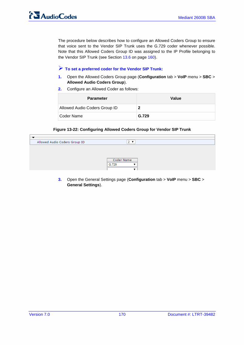
Version 7.0 170 Document #: LTRT-39482
Mediant 2600B SBA
The procedure below describes how to configure an Allowed Coders Group to ensure that voice sent to the Vendor SIP Trunk uses the G.729 coder whenever possible. Note that this Allowed Coders Group ID was assigned to the IP Profile belonging to the Vendor SIP Trunk (see Section 13.6 on page 160).
To set a preferred coder for the Vendor SIP Trunk:
1. Open the Allowed Coders Group page (Configuration tab > VoIP menu > SBC > Allowed Audio Coders Group).
2. Configure an Allowed Coder as follows:
Parameter Value
Allowed Audio Coders Group ID 2
Coder Name G.729
Figure 13-22: Configuring Allowed Coders Group for Vendor SIP Trunk
3. Open the General Settings page (Configuration tab > VoIP menu > SBC > General Settings).

Installation & Maintenance Manual 13. Configuring AudioCodes E-SBC
Version 7.0 171 Skype for Business
Figure 13-23: SBC Preferences Mode
4. From the 'Preferences Mode' drop-down list, select Include Extensions. 5. Click Submit.
13.9 Step 9: SIP TLS Connection Configuration This section describes how to configure the E-SBC for using a TLS connection with the Skype for Business Server 2015 Mediation Server. This is essential for a secure SIP TLS connection.
13.9.1 Step 9a: Configure the NTP Server Address This step describes how to configure the NTP server's IP address. It is recommended to implement an NTP server (Microsoft NTP server or a third-party server) to ensure that the E-SBC receives the accurate and current date and time. This is necessary for validating certificates of remote parties.
To configure the NTP server address:
1. Open the Application Settings page (Configuration tab > System > Time And Day).
2. In the 'NTP Server Address' field, enter the IP address of the NTP server (e.g., 10.15.27.1).

Version 7.0 172 Document #: LTRT-39482
Mediant 2600B SBA
Figure 13-24: Configuring NTP Server Address
3. Click Submit.
13.9.2 Step 9b: Configure the TLS version 1.0 This step describes how to configure the E-SBC to use TLS version 1.0 only. AudioCodes recommends implementing only TLS to avoid flaws in SSL.
To configure the TLS version 1.0:
1. Open the TLS Contexts page (Configuration tab > System menu > TLS Contexts).
2. In the TLS Contexts table, select the required TLS Context index row (usually default index 0 will be used), and then click ‘Edit’.
3. In the ‘TLS Version’ field, enter 1.
Figure 13-25: Configuring TLS version 1.0
4. Click Submit.

Installation & Maintenance Manual 13. Configuring AudioCodes E-SBC
Version 7.0 173 Skype for Business
13.9.3 Step 9c: Configure a Certificate This step describes how to exchange a certificate with Microsoft Certificate Authority (CA). The certificate is used by the E-SBC to authenticate the connection with Skype for Business Server 2015. The procedure involves the following main steps: a. Generating a Certificate Signing Request (CSR). b. Requesting Device Certificate from CA. c. Obtaining Trusted Root Certificate from CA. d. Deploying Device and Trusted Root Certificates on E-SBC.
Note: The Subject Name (CN) field parameter should be identically configured in the DNS Active Directory and Topology Builder (see Section 10 on page 45).
To configure a certificate:
1. Open the TLS Contexts page (Configuration tab > System menu > TLS Contexts).
2. In the TLS Contexts table, select the required TLS Context index row (usually default index 0 will be used), and then click the TLS Context Certificates button, located at the bottom of the TLS Contexts page; the Context Certificates page appears.
3. Under the Certificate Signing Request group, do the following: a. In the 'Subject Name [CN]' field, enter the E-SBC FQDN name
(e.g., ITSP.S4B.interop). b. Fill in the rest of the request fields according to your security provider's
instructions. 4. Click the Create CSR button; a textual certificate signing request is displayed in
the area below the button:
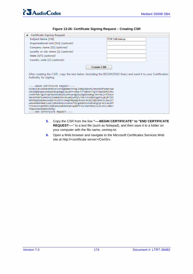
Version 7.0 174 Document #: LTRT-39482
Mediant 2600B SBA
Figure 13-26: Certificate Signing Request – Creating CSR
5. Copy the CSR from the line "----BEGIN CERTIFICATE" to "END CERTIFICATE REQUEST----" to a text file (such as Notepad), and then save it to a folder on your computer with the file name, certreq.txt.
6. Open a Web browser and navigate to the Microsoft Certificates Services Web site at http://<certificate server>/CertSrv.

Installation & Maintenance Manual 13. Configuring AudioCodes E-SBC
Version 7.0 175 Skype for Business
Figure 13-27: Microsoft Certificate Services Web Page
7. Click Request a certificate.

Version 7.0 176 Document #: LTRT-39482
Mediant 2600B SBA
Figure 13-28: Request a Certificate Page
8. Click advanced certificate request, and then click Next.
Figure 13-29: Advanced Certificate Request Page
9. Click Submit a certificate request ..., and then click Next.
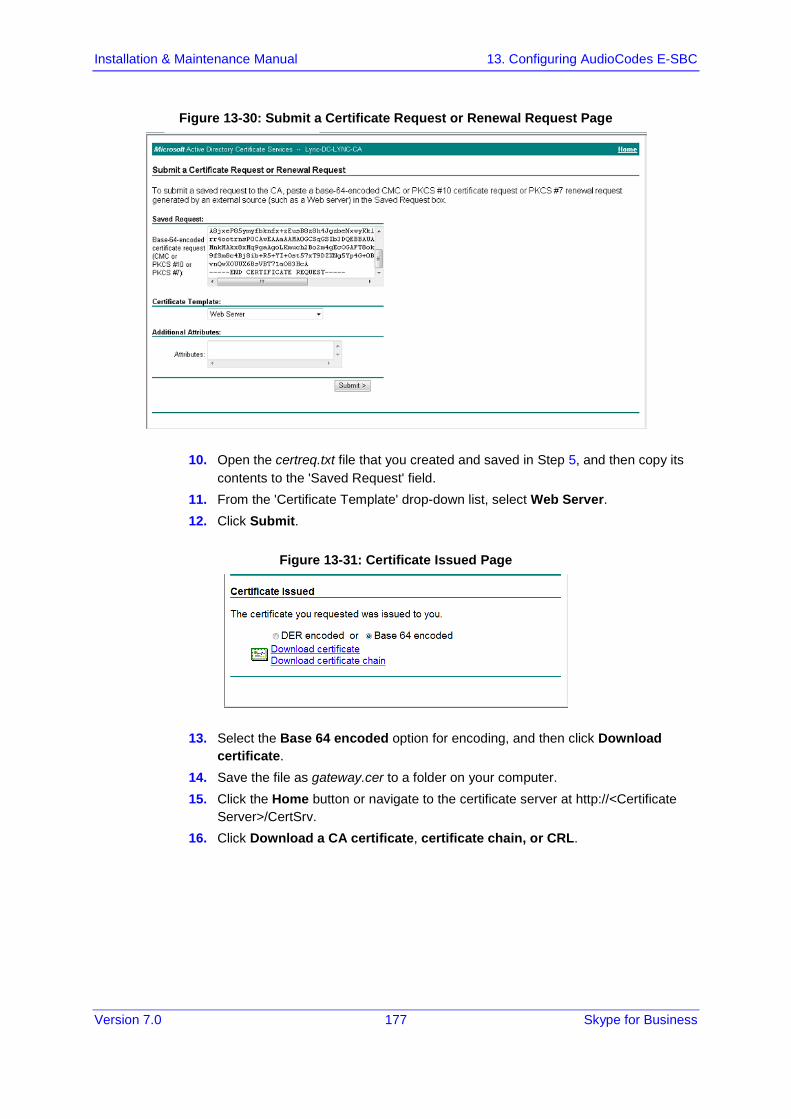
Installation & Maintenance Manual 13. Configuring AudioCodes E-SBC
Version 7.0 177 Skype for Business
Figure 13-30: Submit a Certificate Request or Renewal Request Page
10. Open the certreq.txt file that you created and saved in Step 5, and then copy its contents to the 'Saved Request' field.
11. From the 'Certificate Template' drop-down list, select Web Server. 12. Click Submit.
Figure 13-31: Certificate Issued Page
13. Select the Base 64 encoded option for encoding, and then click Download certificate.
14. Save the file as gateway.cer to a folder on your computer. 15. Click the Home button or navigate to the certificate server at http://<Certificate
Server>/CertSrv. 16. Click Download a CA certificate, certificate chain, or CRL.
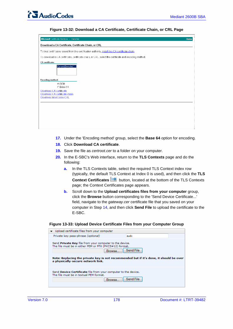
Version 7.0 178 Document #: LTRT-39482
Mediant 2600B SBA
Figure 13-32: Download a CA Certificate, Certificate Chain, or CRL Page
17. Under the 'Encoding method' group, select the Base 64 option for encoding. 18. Click Download CA certificate. 19. Save the file as certroot.cer to a folder on your computer. 20. In the E-SBC's Web interface, return to the TLS Contexts page and do the
following: a. In the TLS Contexts table, select the required TLS Context index row
(typically, the default TLS Context at Index 0 is used), and then click the TLS Context Certificates button, located at the bottom of the TLS Contexts page; the Context Certificates page appears.
b. Scroll down to the Upload certificates files from your computer group, click the Browse button corresponding to the 'Send Device Certificate...' field, navigate to the gateway.cer certificate file that you saved on your computer in Step 14, and then click Send File to upload the certificate to the E-SBC.
Figure 13-33: Upload Device Certificate Files from your Computer Group
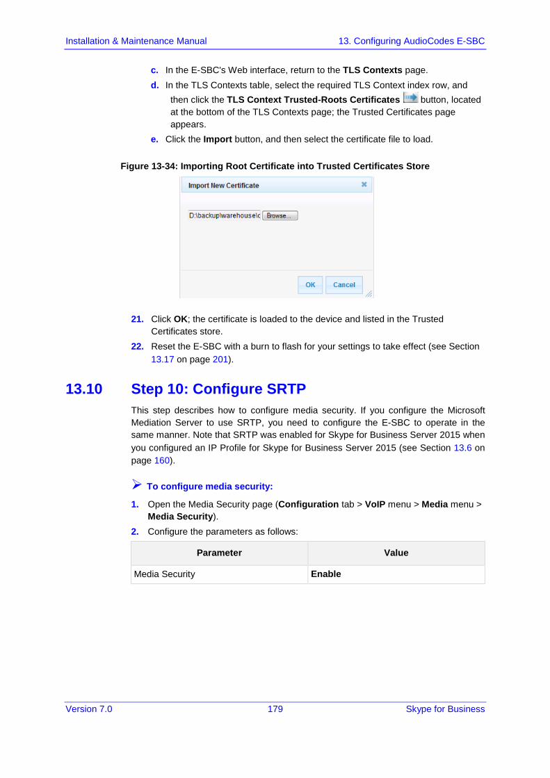
Installation & Maintenance Manual 13. Configuring AudioCodes E-SBC
Version 7.0 179 Skype for Business
c. In the E-SBC's Web interface, return to the TLS Contexts page. d. In the TLS Contexts table, select the required TLS Context index row, and
then click the TLS Context Trusted-Roots Certificates button, located at the bottom of the TLS Contexts page; the Trusted Certificates page appears.
e. Click the Import button, and then select the certificate file to load.
Figure 13-34: Importing Root Certificate into Trusted Certificates Store
21. Click OK; the certificate is loaded to the device and listed in the Trusted Certificates store.
22. Reset the E-SBC with a burn to flash for your settings to take effect (see Section 13.17 on page 201).
13.10 Step 10: Configure SRTP This step describes how to configure media security. If you configure the Microsoft Mediation Server to use SRTP, you need to configure the E-SBC to operate in the same manner. Note that SRTP was enabled for Skype for Business Server 2015 when you configured an IP Profile for Skype for Business Server 2015 (see Section 13.6 on page 160).
To configure media security:
1. Open the Media Security page (Configuration tab > VoIP menu > Media menu > Media Security).
2. Configure the parameters as follows:
Parameter Value
Media Security Enable

Version 7.0 180 Document #: LTRT-39482
Mediant 2600B SBA
Figure 13-35: Configuring SRTP
3. Click Submit. 4. Reset the E-SBC with a burn to flash for your settings to take effect (see Section
13.17 on page 201).

Installation & Maintenance Manual 13. Configuring AudioCodes E-SBC
Version 7.0 181 Skype for Business
13.11 Step 11: Configure Maximum IP Media Channels This step describes how to configure the maximum number of required IP media channels. The number of media channels represents the number of DSP channels that the E-SBC allocates to call sessions.
Note: This step is required only if transcoding is required.
To configure the maximum number of IP media channels:
1. Open the IP Media Settings page (Configuration tab > VoIP menu > SIP Definitions > Advanced Parameters).
Figure 13-36: Configuring Number of Media Channels
2. In the 'Number of Media Channels' field, enter the number of media channels according to your environments transcoding calls (e.g., 30).
3. Click Submit. 4. Reset the E-SBC with a burn to flash for your settings to take effect (see Section
13.17 on page 201).
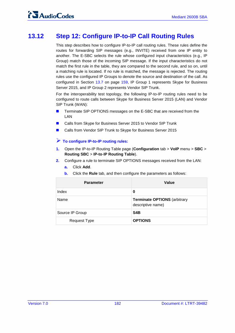
Version 7.0 182 Document #: LTRT-39482
Mediant 2600B SBA
13.12 Step 12: Configure IP-to-IP Call Routing Rules This step describes how to configure IP-to-IP call routing rules. These rules define the routes for forwarding SIP messages (e.g., INVITE) received from one IP entity to another. The E-SBC selects the rule whose configured input characteristics (e.g., IP Group) match those of the incoming SIP message. If the input characteristics do not match the first rule in the table, they are compared to the second rule, and so on, until a matching rule is located. If no rule is matched, the message is rejected. The routing rules use the configured IP Groups to denote the source and destination of the call. As configured in Section 13.7 on page 159, IP Group 1 represents Skype for Business Server 2015, and IP Group 2 represents Vendor SIP Trunk. For the interoperability test topology, the following IP-to-IP routing rules need to be configured to route calls between Skype for Business Server 2015 (LAN) and Vendor SIP Trunk (WAN):
Terminate SIP OPTIONS messages on the E-SBC that are received from the LAN
Calls from Skype for Business Server 2015 to Vendor SIP Trunk
Calls from Vendor SIP Trunk to Skype for Business Server 2015
To configure IP-to-IP routing rules:
1. Open the IP-to-IP Routing Table page (Configuration tab > VoIP menu > SBC > Routing SBC > IP-to-IP Routing Table).
2. Configure a rule to terminate SIP OPTIONS messages received from the LAN: a. Click Add. b. Click the Rule tab, and then configure the parameters as follows:
Parameter Value
Index 0
Name Terminate OPTIONS (arbitrary descriptive name)
Source IP Group S4B
Request Type OPTIONS
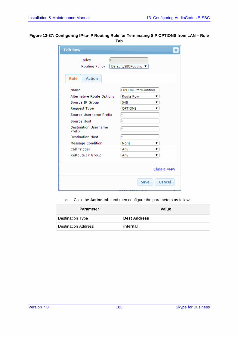
Installation & Maintenance Manual 13. Configuring AudioCodes E-SBC
Version 7.0 183 Skype for Business
Figure 13-37: Configuring IP-to-IP Routing Rule for Terminating SIP OPTIONS from LAN – Rule Tab
c. Click the Action tab, and then configure the parameters as follows:
Parameter Value
Destination Type Dest Address
Destination Address internal
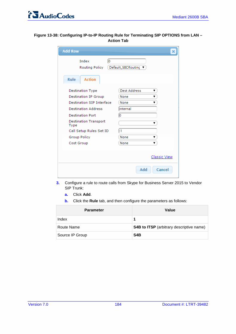
Version 7.0 184 Document #: LTRT-39482
Mediant 2600B SBA
Figure 13-38: Configuring IP-to-IP Routing Rule for Terminating SIP OPTIONS from LAN – Action Tab
3. Configure a rule to route calls from Skype for Business Server 2015 to Vendor
SIP Trunk: a. Click Add. b. Click the Rule tab, and then configure the parameters as follows:
Parameter Value
Index 1
Route Name S4B to ITSP (arbitrary descriptive name)
Source IP Group S4B
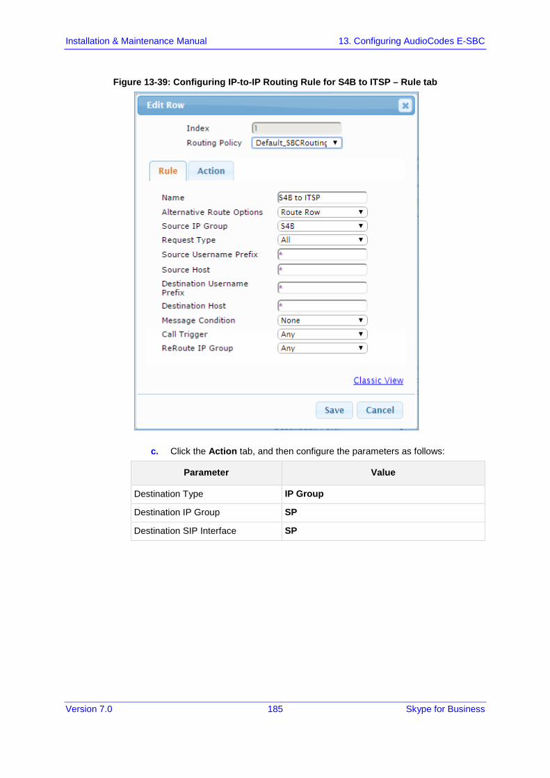
Installation & Maintenance Manual 13. Configuring AudioCodes E-SBC
Version 7.0 185 Skype for Business
Figure 13-39: Configuring IP-to-IP Routing Rule for S4B to ITSP – Rule tab
c. Click the Action tab, and then configure the parameters as follows:
Parameter Value
Destination Type IP Group
Destination IP Group SP
Destination SIP Interface SP

Version 7.0 186 Document #: LTRT-39482
Mediant 2600B SBA
Figure 13-40: Configuring IP-to-IP Routing Rule for S4B to ITSP – Action tab
4. To configure rule to route calls from Vendor SIP Trunk to Skype for Business
Server 2015: a. Click Add. b. Click the Rule tab, and then configure the parameters as follows:
Parameter Value
Index 2
Route Name ITSP to S4B (arbitrary descriptive name)
Source IP Group SP

Installation & Maintenance Manual 13. Configuring AudioCodes E-SBC
Version 7.0 187 Skype for Business
Figure 13-41: Configuring IP-to-IP Routing Rule for ITSP to S4B – Rule tab
c. Click the Action tab, and then configure the parameters as follows:
Parameter Value
Destination Type IP Group
Destination IP Group S4B
Destination SIP Interface S4B

Version 7.0 188 Document #: LTRT-39482
Mediant 2600B SBA
Figure 13-42: Configuring IP-to-IP Routing Rule for ITSP to S4B – Action tab
The configured routing rules are shown in the figure below:
Figure 13-43: Configured IP-to-IP Routing Rules in IP-to-IP Routing Table

Installation & Maintenance Manual 13. Configuring AudioCodes E-SBC
Version 7.0 189 Skype for Business
Note: The routing configuration may change according to your specific deployment topology.
13.13 Step 13: Configure IP-to-IP Manipulation Rules This step describes how to configure IP-to-IP manipulation rules. These rules manipulate the source and / or destination number. The manipulation rules use the configured IP Groups to denote the source and destination of the call. As configured in Section 13.7 on page 159, IP Group 0 represents Skype for Business Server 2015, and IP Group 1 represents Vendor SIP Trunk.
Note: Adapt the manipulation table according to you environment dial plan.
For this interoperability test topology, a manipulation is configured to add the "+" (plus sign) to the destination number for calls from the Vendor SIP Trunk IP Group to the Skype for Business Server 2015 IP Group for any destination username prefix.
To configure a number manipulation rule:
1. Open the IP-to-IP Outbound Manipulation page (Configuration tab > VoIP menu > SBC > Manipulations SBC > IP-to-IP Outbound).
2. Click Add. 3. Click the Rule tab, and then configure the parameters as follows:
Parameter Value
Index 0
Name Add + toward S4B
Source IP Group SP
Destination IP Group S4B
Destination Username Prefix * (asterisk sign)

Version 7.0 190 Document #: LTRT-39482
Mediant 2600B SBA
Figure 13-44: Configuring IP-to-IP Outbound Manipulation Rule – Rule Tab
4. Click the Action tab, and then configure the parameters as follows:
Parameter Value
Manipulated Item Destination URI
Prefix to Add + (plus sign)

Installation & Maintenance Manual 13. Configuring AudioCodes E-SBC
Version 7.0 191 Skype for Business
Figure 13-45: Configuring IP-to-IP Outbound Manipulation Rule - Action Tab
5. Click Submit. The figure below shows an example of configured IP-to-IP outbound manipulation rules for calls between Skype for Business Server 2015 IP Group and Vendor SIP Trunk IP Group:
Figure 13-46: Example of Configured IP-to-IP Outbound Manipulation Rules

Version 7.0 192 Document #: LTRT-39482
Mediant 2600B SBA
Rule Index Description
1 Calls from ITSP IP Group to S4B IP Group with any destination number (*), add "+" to the prefix of the destination number.
2 Calls from S4B IP Group to ITSP IP Group with the prefix destination number "+", remove "+" from this prefix.
3 Calls from S4B IP Group to ITSP IP Group with source number prefix "+", remove the "+" from this prefix.
13.14 Step 14: Configure Message Manipulation Rules This step describes how to configure SIP message manipulation rules. SIP message manipulation rules can include insertion, removal, and/or modification of SIP headers. Manipulation rules are grouped into Manipulation Sets, enabling you to apply multiple rules to the same SIP message (IP entity). Once you have configured the SIP message manipulation rules, you need to assign them to the relevant IP Group (in the IP Group table) and determine whether they must be applied to inbound or outbound messages.
To configure SIP message manipulation rule:
1. Open the Message Manipulations page (Configuration tab > VoIP menu > SIP Definitions > Msg Policy & Manipulation > Message Manipulations).
2. Configure a new manipulation rule (Manipulation Set 4) for Vendor SIP Trunk. This rule applies to messages sent to the Vendor SIP Trunk IP Group in a call forward scenario. This replaces the user part of the SIP From Header with the value from the SIP History-Info Header.
Parameter Value
Index 0
Name Call Forward
Manipulation Set ID 4
Condition header.history-info.0 regex (<sip:)(.*)(@)(.*)
Action Subject header.from.url.user
Action Type Modify
Action Value $3

Installation & Maintenance Manual 13. Configuring AudioCodes E-SBC
Version 7.0 193 Skype for Business
Figure 13-47: Configuring SIP Message Manipulation Rule 0 (for Vendor SIP Trunk)
3. Configure another manipulation rule (Manipulation Set 4) for Vendor SIP Trunk. This rule is applied to response messages sent to the Vendor SIP Trunk IP Group for Rejected Calls initiated by the Skype for Business Server 2015 IP Group. This replaces the method type ‘503’ with the value ‘480’, because Vendor SIP Trunk not recognizes ‘503’ method type.
Parameter Value
Index 7
Name Reject Cause
Manipulation Set ID 4
Message Type any.response
Condition header.request-uri.methodtype=='503'
Action Subject header.request-uri.methodtype
Action Type Modify
Action Value '480'
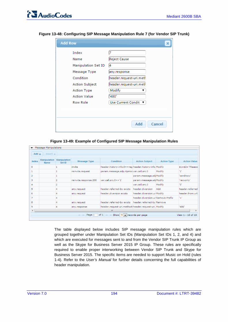
Version 7.0 194 Document #: LTRT-39482
Mediant 2600B SBA
Figure 13-48: Configuring SIP Message Manipulation Rule 7 (for Vendor SIP Trunk)
Figure 13-49: Example of Configured SIP Message Manipulation Rules
The table displayed below includes SIP message manipulation rules which are grouped together under Manipulation Set IDs (Manipulation Set IDs 1, 2, and 4) and which are executed for messages sent to and from the Vendor SIP Trunk IP Group as well as the Skype for Business Server 2015 IP Group. These rules are specifically required to enable proper interworking between Vendor SIP Trunk and Skype for Business Server 2015. The specific items are needed to support Music on Hold (rules 1-4). Refer to the User’s Manual for further details concerning the full capabilities of header manipulation.

Installation & Maintenance Manual 13. Configuring AudioCodes E-SBC
Version 7.0 195 Skype for Business
Table 13-1: Rule Index
Rule Description Reason for Introducing Rule
0
This rule applies to messages sent to the Vendor SIP Trunk IP Group in a call forward scenario. This replaces the user part of the SIP From Header with the value from the SIP History-Info Header.
For Call Forward scenarios, Vendor SIP Trunk needs that User part in SIP From Header will be defined number. In order to do this, User part of the SIP From Header replaced with the value from History-Info Header.
1 If the manipulation rule Index 0 (above) is executed, then the following rule is also executed. It removes History Info Header.
2
For every SIP Re-INVITE request with SDP, where RTP mode = "sendonly" (occurs in a S4B-initiated Hold), create a variable and set it to '1'. This variable manages how the call will be handled in each state (answer, request, etc.). In the Call Park scenario,
Microsoft S4B sends Re-INVITE messages twice. The first message is sent with the SDP, where the RTP mode is set to “a=inactive”. The second message is sent with “a=sendonly”. The Vendor SIP Trunk has a problem recognizing two sequential Re-INVITE messages with different RTP modes. This causes the loss of the Music On Hold functionality in the Call Park scenario. These four rules are applied to work around this limitation.
3
If the previous manipulation rule (Index 0) is executed, then the following rule is also executed on the same SIP message: if RTP mode within the SDP is set to “sendonly”, change it to “sendrecv”.
4
This rule attempts to normalize the call processing state back to S4B for the correct reply to the initially received “sendonly”. For every SIP Re-INVITE message with the variable set to '1', change RTP mode to "recvonly". This SIP Re-INVITE message is the response sent from the Vendor SIP Trunk to the S4B-initiated Hold.
5
If the manipulation rule Index 2 (above) is executed, then the following rule is also executed. If the variable is determined to be set to "1" (in the previous manipulation rule), then set it to “0” to normalize the call processing state. S4B now sends Music on Hold to the Vendor SIP Trunk even without the Vendor SIP Trunk knowing how to receive MoH. The call is now truly on hold with MoH.
6 This rule applies to messages sent to Vendor SIP Trunk IP Group. This replaces the host part of the Referred-By Header with the value from the SIP From Header.
For Call Transfer initiated by Skype for Business Server 2015, Vendor SIP Trunk needs to replace the Host part of the SIP Referred-By Header with the value from the SIP From Header and user part of the From Header with the value from Referred-By Header.
7 If the manipulation rule Index 6 (above) is executed, then the following rule is also executed. It remove prefix ‘+47’ from the Referred-By Header.
8 This rule applies to messages sent to the Vendor SIP Trunk IP Group. This rule replaces the user part of the From Header with the value from Referred-By Header.

Version 7.0 196 Document #: LTRT-39482
Mediant 2600B SBA
4. Assign Manipulation Set IDs 1 and 2 to the Skype for Business 2015 IP Group: a. Open the IP Group Table page (Configuration tab > VoIP menu > VoIP
Network > IP Group Table). b. Select the row of the Skype for Business 2015 IP Group, and then click Edit. c. Click the SBC tab. d. Set the 'Inbound Message Manipulation Set' field to 1. e. Set the 'Outbound Message Manipulation Set' field to 2.
Figure 13-50: Assigning Manipulation Set to the Skype for Business 2015 IP Group
a. Click Submit.
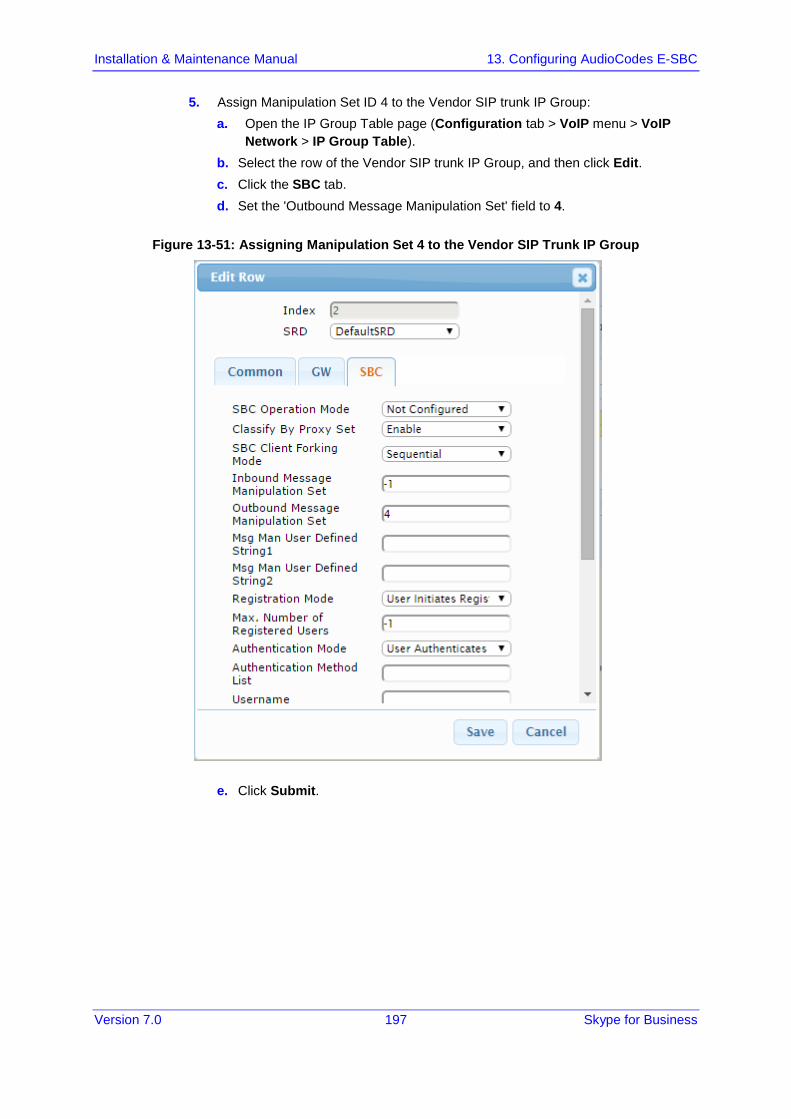
Installation & Maintenance Manual 13. Configuring AudioCodes E-SBC
Version 7.0 197 Skype for Business
5. Assign Manipulation Set ID 4 to the Vendor SIP trunk IP Group: a. Open the IP Group Table page (Configuration tab > VoIP menu > VoIP
Network > IP Group Table). b. Select the row of the Vendor SIP trunk IP Group, and then click Edit. c. Click the SBC tab. d. Set the 'Outbound Message Manipulation Set' field to 4.
Figure 13-51: Assigning Manipulation Set 4 to the Vendor SIP Trunk IP Group
e. Click Submit.
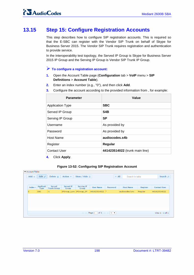
Version 7.0 198 Document #: LTRT-39482
Mediant 2600B SBA
13.15 Step 15: Configure Registration Accounts This step describes how to configure SIP registration accounts. This is required so that the E-SBC can register with the Vendor SIP Trunk on behalf of Skype for Business Server 2015. The Vendor SIP Trunk requires registration and authentication to provide service. In the interoperability test topology, the Served IP Group is Skype for Business Server 2015 IP Group and the Serving IP Group is Vendor SIP Trunk IP Group.
To configure a registration account:
1. Open the Account Table page (Configuration tab > VoIP menu > SIP Definitions > Account Table).
2. Enter an index number (e.g., "0"), and then click Add. 3. Configure the account according to the provided information from , for example:
Parameter Value
Application Type SBC
Served IP Group S4B
Serving IP Group SP
Username As provided by
Password As provided by
Host Name audiocodes.s4b
Register Regular
Contact User 441423514022 (trunk main line)
4. Click Apply.
Figure 13-52: Configuring SIP Registration Account
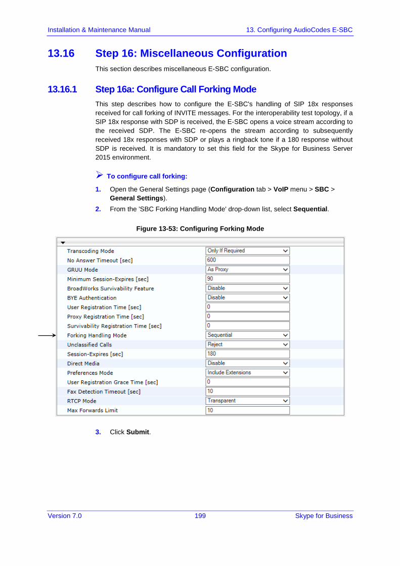
Installation & Maintenance Manual 13. Configuring AudioCodes E-SBC
Version 7.0 199 Skype for Business
13.16 Step 16: Miscellaneous Configuration This section describes miscellaneous E-SBC configuration.
13.16.1 Step 16a: Configure Call Forking Mode This step describes how to configure the E-SBC's handling of SIP 18x responses received for call forking of INVITE messages. For the interoperability test topology, if a SIP 18x response with SDP is received, the E-SBC opens a voice stream according to the received SDP. The E-SBC re-opens the stream according to subsequently received 18x responses with SDP or plays a ringback tone if a 180 response without SDP is received. It is mandatory to set this field for the Skype for Business Server 2015 environment.
To configure call forking:
1. Open the General Settings page (Configuration tab > VoIP menu > SBC > General Settings).
2. From the 'SBC Forking Handling Mode' drop-down list, select Sequential.
Figure 13-53: Configuring Forking Mode
3. Click Submit.
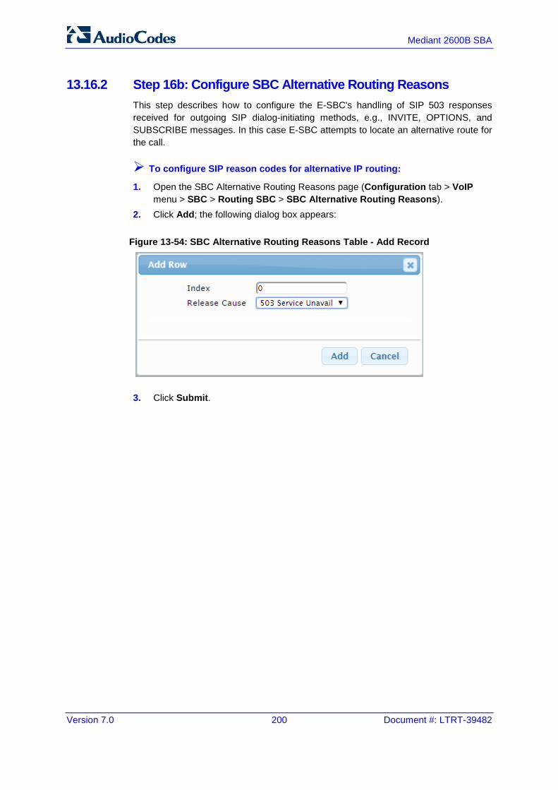
Version 7.0 200 Document #: LTRT-39482
Mediant 2600B SBA
13.16.2 Step 16b: Configure SBC Alternative Routing Reasons This step describes how to configure the E-SBC's handling of SIP 503 responses received for outgoing SIP dialog-initiating methods, e.g., INVITE, OPTIONS, and SUBSCRIBE messages. In this case E-SBC attempts to locate an alternative route for the call.
To configure SIP reason codes for alternative IP routing:
1. Open the SBC Alternative Routing Reasons page (Configuration tab > VoIP menu > SBC > Routing SBC > SBC Alternative Routing Reasons).
2. Click Add; the following dialog box appears:
Figure 13-54: SBC Alternative Routing Reasons Table - Add Record
3. Click Submit.
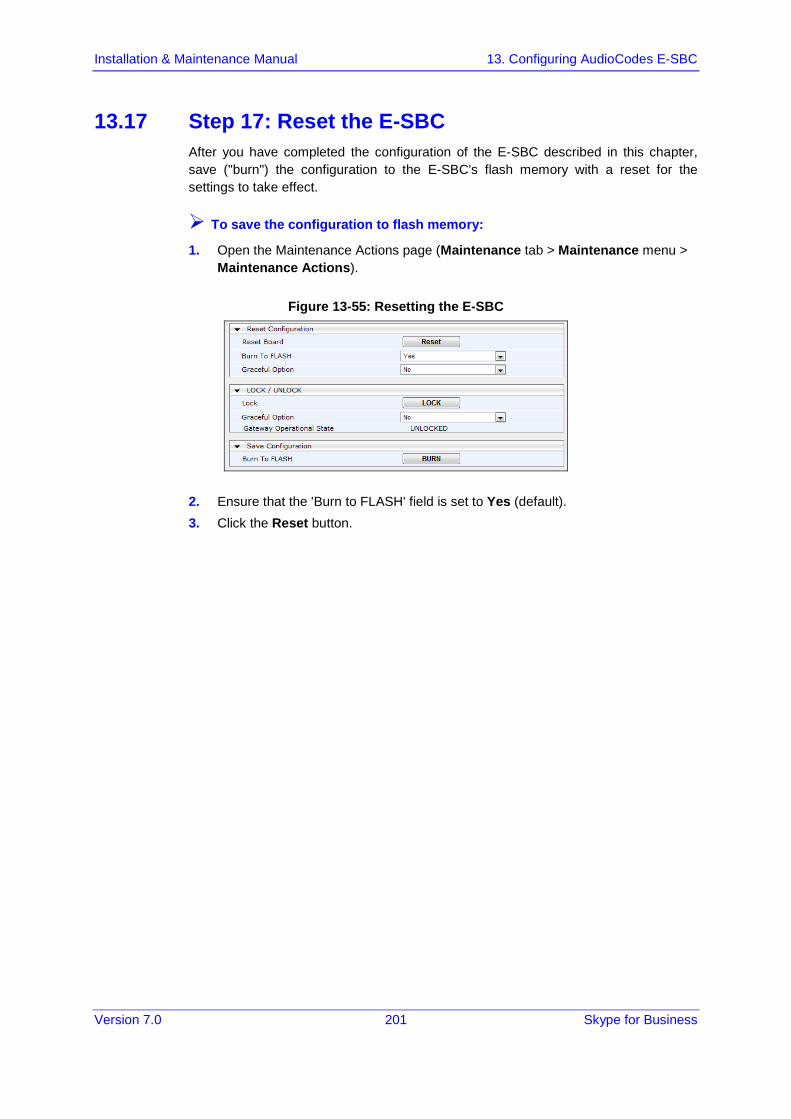
Installation & Maintenance Manual 13. Configuring AudioCodes E-SBC
Version 7.0 201 Skype for Business
13.17 Step 17: Reset the E-SBC After you have completed the configuration of the E-SBC described in this chapter, save ("burn") the configuration to the E-SBC's flash memory with a reset for the settings to take effect.
To save the configuration to flash memory:
1. Open the Maintenance Actions page (Maintenance tab > Maintenance menu > Maintenance Actions).
Figure 13-55: Resetting the E-SBC
2. Ensure that the 'Burn to FLASH' field is set to Yes (default). 3. Click the Reset button.

Version 7.0 202 Document #: LTRT-39482
Mediant 2600B SBA
This page is intentionally left blank.

Part VI Upgrading SBA Components
This part describes how to upgrade SBA components.


Version 7.0 205 Skype for Business
Installation & Maintenance Manual 14. Upgrading MSFT and CU System Components
14 Upgrading MSFT and CU System Components This section describes how to update system components using the SBA interface. The following components can be updated:
Microsoft system components
CU updates
The 'LyncServerUpdateInstaller.exe' provided by Microsoft installs all of the required Microsoft installation component files in a single action.
To update system components:
1. Login to the SBA Management Interface. 2. In the SBA Management Interface, select the Tools tab, and then select the
'System Update' check box (insert red line around System Update).
Figure 14-1: Tools-System Update

Mediant 2600B SBA
Version 7.0 206 Document #: LTRT-39482
The System Update screen is displayed:
Figure 14-2: System Update Screen
The currently installed Microsoft components are listed in the Installed Components pane.
3. In the ‘File to upload’ field, click Browse to select the 'LyncServerUpdateInstaller.exe' file to upload, and then click Apply. The following screen is displayed:
Figure 14-3: System Update Microsoft Components

Version 7.0 207 Skype for Business
Installation & Maintenance Manual 14. Upgrading MSFT and CU System Components
Wait a few minutes for the update to apply. At the end of the process, the System Logs out automatically and the login screen is displayed:
Figure 14-4: Login Screen after Automatic Log Out
4. Enter your login and password details, and if the Terms and Conditions checkbox is displayed, select it and then click Login.
5. Select the Tools tab, and then select the 'System Update' check box. 6. Verify that the new components and respective version numbers are displayed in
the Installed Components pane.

Mediant 2600B SBA
Version 7.0 208 Document #: LTRT-39482
This page is intentionally left blank.
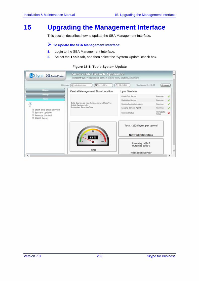
Version 7.0 209 Skype for Business
Installation & Maintenance Manual 15. Upgrading the Management Interface
15 Upgrading the Management Interface This section describes how to update the SBA Management Interface.
To update the SBA Management Interface:
1. Login to the SBA Management Interface. 2. Select the Tools tab, and then select the 'System Update' check box.
Figure 15-1: Tools-System Update

Mediant 2600B SBA
Version 7.0 210 Document #: LTRT-39482
The System Update screen is displayed:
Figure 15-2: System Update Screen
3. In the ‘File to upload’ field, click Browse to select the file to upload and then click Apply; the following screen is displayed:
Figure 15-3: System Update Message-SBA Management Interface Version
A time-stamp of the time that you commenced the System Update is displayed in the right-hand pane.
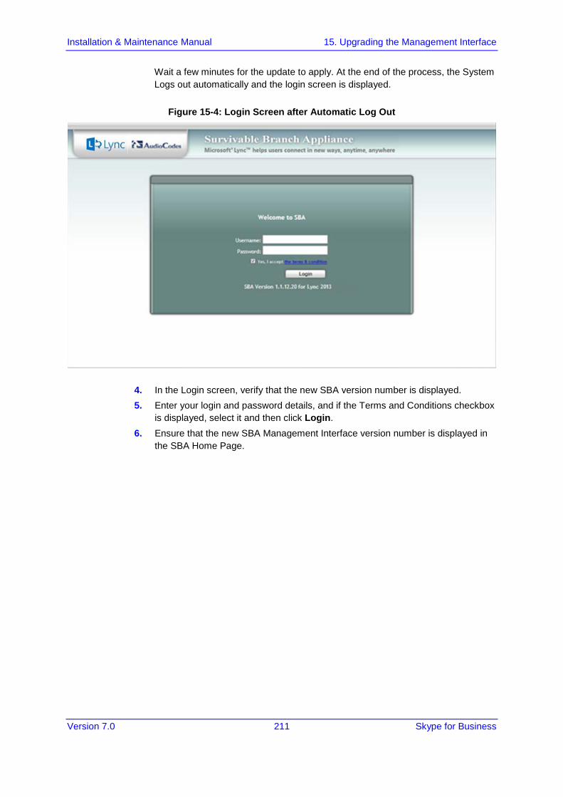
Version 7.0 211 Skype for Business
Installation & Maintenance Manual 15. Upgrading the Management Interface
Wait a few minutes for the update to apply. At the end of the process, the System Logs out automatically and the login screen is displayed.
Figure 15-4: Login Screen after Automatic Log Out
4. In the Login screen, verify that the new SBA version number is displayed. 5. Enter your login and password details, and if the Terms and Conditions checkbox
is displayed, select it and then click Login. 6. Ensure that the new SBA Management Interface version number is displayed in
the SBA Home Page.
Mediant 2600B SBA
Version 7.0 212 Document #: LTRT-39482
16 Upgrading using the SBA ProConnect A customer with large SBA deployments might experience difficulties updating their SBA manually. Consequently, for better servicing of such deployments, AudioCodes now offers a new application 'SBA ProConnect', which is a Web Management tool for the purposes of easily installing Microsoft Cumulative Updates (CU) and for upgrading Skype for Business Server from a central location to the SBA devices.
Note: For more information, refer to the SBA ProConnect User's Manual and contact your AudioCodes representative.

Part VII Upgrade and Recovery

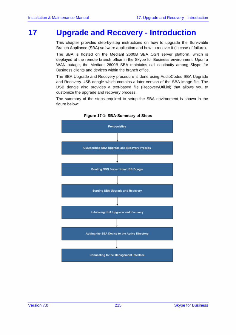
Version 7.0 215 Skype for Business
Installation & Maintenance Manual 17. Upgrade and Recovery - Introduction
17 Upgrade and Recovery - Introduction This chapter provides step-by-step instructions on how to upgrade the Survivable Branch Appliance (SBA) software application and how to recover it (in case of failure). The SBA is hosted on the Mediant 2600B SBA OSN server platform, which is deployed at the remote branch office in the Skype for Business environment. Upon a WAN outage, the Mediant 2600B SBA maintains call continuity among Skype for Business clients and devices within the branch office. The SBA Upgrade and Recovery procedure is done using AudioCodes SBA Upgrade and Recovery USB dongle which contains a later version of the SBA image file. The USB dongle also provides a text-based file (RecoveryUtil.ini) that allows you to customize the upgrade and recovery process. The summary of the steps required to setup the SBA environment is shown in the figure below:
Figure 17-1: SBA-Summary of Steps

Version 7.0 216 Document #: LTRT-39482
Mediant 2600B SBA
This page is intentionally left blank.

Version 7.0 217 Skype for Business
Installation & Maintenance Manual 18. Upgrade and Recovery - Prerequisites
18 Upgrade and Recovery - Prerequisites Before you can begin the SBA upgrade and recovery, do the following:
Ensure that you have received the USB dongle in your SBA kit (from AudioCodes).
Figure 18-1: SBA Upgrade and Recovery USB Dongle
Set the location of the SBA image file that you want to burn to the OSN server to one of the following:
SBA Upgrade and Recovery USB dongle
FTP server
Local network
Recovery Partition (drive D:\) on the OSN hard disk
If you have recently obtained a later SBA image file version, it is recommended to copy it to the USB dongle (prior to performing the SBA upgrade and recovery), and then delete the old image from the USB dongle (the old image resides in the root folder with the file extension, *.wim).
Note:
• The USB dongle is supplied with an image of the SBA upgrade and recovery. • When using the recovery partition of the OSN server as the location for the SBA image
file, you must disable the partitions and disable disk formatting capabilities, using the RecoveryUtil.ini file (see Section 'Creating Disk Partitions' on page 220).
• You can also download the SBA image file from AudioCodes Web site at http://www.audiocodes.com/sba or obtain a DVD from AudioCodes with the new version.

Version 7.0 218 Document #: LTRT-39482
Mediant 2600B SBA
This page is intentionally left blank.

Version 7.0 219 Skype for Business
Installation & Maintenance Manual 19. Customizing SBA Upgrade and Recovery
19 Customizing SBA Upgrade and Recovery The RecoveryUtil.ini file is a text-based file that is located in the root directory on the supplied USB dongle. This file contains parameters for defining various options relating to the SBA upgrade and recovery process. The RecoveryUtil.ini file is supplied with recommended configuration settings. However, you can modify them to suit your requirements.
Warning: Before plugging the USB dongle into the PC, ensure that the PC boot priority from USB is disabled or it’s set to the last priority. This setting is crucial. If your PC is set to boot from USB before it attempts to boot from the HDMX, then if your PC restarts while the USB dongle is plugged in, your PC boots from the USB dongle, thereby reformatting your PC and damaging your PC operating system.
The procedure below describes how to modify the RecoveryUtil.ini file.
To modify the RecoveryUtil.ini file:
1. Plug the USB dongle into a USB port on the PC. 2. Open (using a text-based editor such as Notepad) the RecoveryUtil.ini file located
on the USB dongle. 3. Perform the required modifications, as described in the subsequent subsections. 4. Save and close the file. 5. Remove the USB dongle from the PC.
19.1 Defining Manual or Automatic Start You can configure the SBA upgrade and recovery to start manually or automatically, by using the RecoveryStartType parameter:
Manually (recommended and default): To start the SBA upgrade and recovery manually, set the RecoveryStartType parameter to 1, as shown below:
[Execution] RecoveryStartType= 1
With this setting, you need to run the upgrade and recovery utility script manually from the DOS shell command line (using a serial communication console, i.e. HyperTerminal).
Automatic: To start the SBA upgrade and recovery automatically, set the RecoveryStartType parameter to 0, as shown below:
[Execution] RecoveryStartType= 0
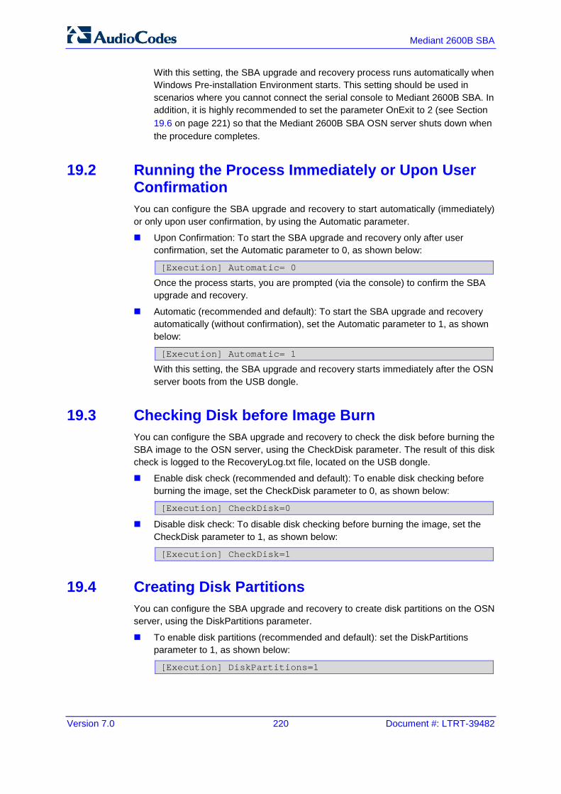
Version 7.0 220 Document #: LTRT-39482
Mediant 2600B SBA
With this setting, the SBA upgrade and recovery process runs automatically when Windows Pre-installation Environment starts. This setting should be used in scenarios where you cannot connect the serial console to Mediant 2600B SBA. In addition, it is highly recommended to set the parameter OnExit to 2 (see Section 19.6 on page 221) so that the Mediant 2600B SBA OSN server shuts down when the procedure completes.
19.2 Running the Process Immediately or Upon User Confirmation You can configure the SBA upgrade and recovery to start automatically (immediately) or only upon user confirmation, by using the Automatic parameter.
Upon Confirmation: To start the SBA upgrade and recovery only after user confirmation, set the Automatic parameter to 0, as shown below:
[Execution] Automatic= 0
Once the process starts, you are prompted (via the console) to confirm the SBA upgrade and recovery.
Automatic (recommended and default): To start the SBA upgrade and recovery automatically (without confirmation), set the Automatic parameter to 1, as shown below:
[Execution] Automatic= 1
With this setting, the SBA upgrade and recovery starts immediately after the OSN server boots from the USB dongle.
19.3 Checking Disk before Image Burn You can configure the SBA upgrade and recovery to check the disk before burning the SBA image to the OSN server, using the CheckDisk parameter. The result of this disk check is logged to the RecoveryLog.txt file, located on the USB dongle.
Enable disk check (recommended and default): To enable disk checking before burning the image, set the CheckDisk parameter to 0, as shown below:
[Execution] CheckDisk=0
Disable disk check: To disable disk checking before burning the image, set the CheckDisk parameter to 1, as shown below:
[Execution] CheckDisk=1
19.4 Creating Disk Partitions You can configure the SBA upgrade and recovery to create disk partitions on the OSN server, using the DiskPartitions parameter.
To enable disk partitions (recommended and default): set the DiskPartitions parameter to 1, as shown below:
[Execution] DiskPartitions=1

Version 7.0 221 Skype for Business
Installation & Maintenance Manual 19. Customizing SBA Upgrade and Recovery
Notes:
• The SBA is shipped with an image on the recovery partition (D:\ drive on the OSN hard disk). If the parameter DiskPartitions is set to 1, then this image is deleted. Therefore, before partitioning, it is recommended to backup the file to an external storage.
• If the parameter DiskPartitions is set to 1, then the image location can’t be the recovery partition
With this setting, you must also set the following:
Partition Size: Set the main partition size in Megabytes:
[DiskPartitions] MainPartitionSize=100000
Notes:
• The recommended main partition size is ''100000'' (i.e., ''100'' Gigabytes). • Ensure that the secondary partition is at least 10 GB, as it is used to hold SBA image
file, which is downloaded through FTP.
Format Partitions: Format disk partitions into main (C:\) and secondary (D:\) partitions, by setting the FormatPartitions parameter to 1, as shown below. (If set to 0, disk partitions are not formatted).
[DiskPartitions] FormatPartitions=1
To disable creation of disk partitions: set the DiskPartitions parameter to 0, as shown below:
[Execution] DiskPartitions=0
19.5 Enabling SBA Image Burn on Primary Partition You can configure the SBA upgrade and recovery to burn the SBA image on the main partition, using the RecoverImange parameter.
To enable image burn on primary partitions (recommended and default): Set the RecoverImange parameter to 1, as shown below:
[Execution] RecoverImange =1
To disable image burn on primary partitions: Set the RecoverImange parameter to 0, as shown below:
[Execution] RecoverImange =0
19.6 Defining Exit Operation upon Process Completion You can configure the SBA upgrade and recovery to perform a specific operation upon the completion of the process, using the OnExit parameter.
Start command prompt: Set the OnExit parameter to 0 to start the command prompt upon process completion:
[Execution] OnExit = 0

Version 7.0 222 Document #: LTRT-39482
Mediant 2600B SBA
Reboot OSN server: Set the OnExit parameter to 1 to reboot the OSN server upon process completion:
[Execution] OnExit = 1
Shut down OSN server: Set the OnExit parameter to 2 to shut down the OSN server upon process completion:
[Execution] OnExit = 2
Notes: The recommendation for this configuration is as follows:
• If you are monitoring the procedure by connecting a monitor or serial console, it’s recommended to set OnExit to 0. This setting displays log messages on the console, indicating the progress of the SBA upgrade and recovery process.
• If the process is performing automatically without monitoring via a monitor or serial console, you must set OnExit to 2. In this case, at the end of the upgrade and recovery process, the OSN server shuts down.
19.7 Defining Network Parameters You can configure the network parameters for the SBA upgrade and recovery process, using the parameters under the [NetworkCardConfiguration] section in the *.ini file.
Note: These network settings are used only for Skype for Business between the OSN and an FTP server or a local network for downloading the image file, as described on page 223. The IP address of the OSN LAN port is assigned only after initialization (by a DHCP server or manually), as described on page 79.
Use DHCP for obtaining IP address (recommended and default): Set the EnableDhcp to 1, as shown below:
[NetworkCardConfiguration] EnableDhcp=1
This is only applicable if you have a DHCP server in your network.
Manually (Static) define IP address: Set the EnableDhcp to 0, as shown below:
[NetworkCardConfiguration] EnableDhcp=0
When set for static IP address, configure the static network address, as shown below:
IpAddress: Defines the static IP address:
[NetworkCardConfiguration] IpAddress=10.21.22.55
SubnetMask: Defines the subnet:
[NetworkCardConfiguration] SubnetMask=255.255.0.0
DefaultGateway: Defines the default gateway:
[NetworkCardConfiguration] DefaultGateway=10.21.0.1
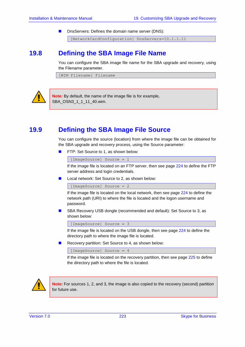
Version 7.0 223 Skype for Business
Installation & Maintenance Manual 19. Customizing SBA Upgrade and Recovery
DnsServers: Defines the domain name server (DNS):
[NetworkCardConfiguration] DnsServers=10.1.1.11
19.8 Defining the SBA Image File Name You can configure the SBA image file name for the SBA upgrade and recovery, using the Filename parameter.
[WIM Filename] Filename
Note: By default, the name of the image file is for example, SBA_OSN3_1_1_11_40.wim.
19.9 Defining the SBA Image File Source You can configure the source (location) from where the image file can be obtained for the SBA upgrade and recovery process, using the Source parameter:
FTP: Set Source to 1, as shown below:
[ImageSource] Source = 1
If the image file is located on an FTP server, then see page 224 to define the FTP server address and login credentials.
Local network: Set Source to 2, as shown below:
[ImageSource] Source = 2
If the image file is located on the local network, then see page 224 to define the network path (URI) to where the file is located and the logon username and password.
SBA Recovery USB dongle (recommended and default): Set Source to 3, as shown below:
[ImageSource] Source = 3
If the image file is located on the USB dongle, then see page 224 to define the directory path to where the image file is located.
Recovery partition: Set Source to 4, as shown below:
[ImageSource] Source = 4
If the image file is located on the recovery partition, then see page 225 to define the directory path to where the file is located.
Note: For sources 1, 2, and 3, the image is also copied to the recovery (second) partition for future use.

Version 7.0 224 Document #: LTRT-39482
Mediant 2600B SBA
19.9.1 Defining the FTP If the image file is located on an FTP server (i.e., [ImageSource] Source = 1, as defined on page 223), then you need to define the FTP server address and login credentials:
[FtpSettings] Site: Defines the IP address or FQDN of the FTP server (FTP server can be in the local network or on the Internet):
[FtpSettings] Site=10.13.4.115
[FtpSettings] User: Defines the FTP login user name:
[FtpSettings] User=Admin
[FtpSettings] Password: Defines the FTP login password:
[FtpSettings] Password=1234
Note: The image file must be located on the root of the FTP server.
19.9.2 Defining the Local Network If the image file is located on a local network (i.e., [ImageSource] Source = 2, as defined on page 223), then you need to define the network path (URI) to where the file is located and the access username and password.
[LocalNetworkSettings] Path: Defines the network URI:
[LocalNetworkSettings] Path=\\192.168.1.4\images
[LocalNetworkSettings] User: Defines the login user name:
[LocalNetworkSettings] User=audiocodes\john.smith
[LocalNetworkSettings] Password: Defines the password:
[LocalNetworkSettings] Password=1234
19.9.3 Defining the Disk On Key If the SBA image file is located on the USB dongle (i.e., [ImageSource] Source = 3, as defined on page 223 ), then you must define the directory path to where the image file is located. This is defined using the [DOKsettings] DirectoryPath parameter. The path must be set without the volume (for example, "\recovery\"). The application searches for this directory in all drives. For the USB root directory, set this parameter to "\" (default and recommended), as shown below:
[DOKsettings] DirectoryPath=\

Version 7.0 225 Skype for Business
Installation & Maintenance Manual 19. Customizing SBA Upgrade and Recovery
19.9.4 Defining the Recovery Partition If the SBA image file is located on the recovery partition (i.e., [ImageSource] Source = 4), then you need to define the directory path to where the file is located. This is defined using the [RecoveryPartition] DirectoryPath parameter. The path must be defined without the volume (for example, "\recovery\"). The application searches all the drives for this directory. For recovery partition root, set this parameter to "\" (recommended and default):
[RecoveryPartition] DirectoryPath=\
19.10 Defining the MAC Address Prefix You can configure the MAC address (prefix or full address) of the Mediant 2600B SBA for which the SBA upgrade and recovery process can run, using the MacPrefix parameter. This prevents accidental running of the SBA upgrade and recovery on your PC. If not configured, the procedure runs on any system.
[User Confirm] MacPrefix=00-45-B1-22-49-B1
You can define several MAC addresses by suffixing the MacPrefix parameter with an index number for each MAC address, as shown in the example below:
[User Confirm] MacPrefix=01034E MacPrefix1=0 MacPrefix7=01-03-5C MacPrefix3=01-03
The default MAC addresses set in the file include the following:
MacPrefix=00-80-82
MacPrefix1=00-40-9E
MacPrefix2=00-0B-AB

Version 7.0 226 Document #: LTRT-39482
Mediant 2600B SBA
This page is intentionally left blank.

Version 7.0 227 Skype for Business
Installation & Maintenance Manual 20. SBA Upgrade and Recovery
20 SBA Upgrade and Recovery After you have customized the SBA upgrade and recovery process using the RecoveryUtil.ini file (see page 219), you can start the upgrade and recovery process. The process can be done with or without online monitoring.
Note: When the process completes, you can view the results of the SBA upgrade and recovery process in the log file RecoveryLog.txt. This file is located on the USB dongle.
Warnings: Before proceeding, note the following:
• Contact your AudioCodes representative to verify if there are any required updates to the BIOS.
• Enter the OSN server's BIOS setup and set the highest boot priority to the USB dongle and not the HDMX.
20.1 Starting Process without Monitoring The procedure below describes how to start the SBA upgrade and recovery process without monitoring.
To start SBA upgrade and recovery without monitoring:
1. Open (using a text editor such as Notepad) the RecoveryUtil.ini file and then set the OnExit parameter to 2 so that the OSN server shuts down upon SBA upgrade and recovery completion:
[Execution] OnExit = 2
2. Save and close the RecoveryUtil.ini file.
3. Plug the USB dongle into the USB port OSN on the Mediant 2600B SBA OSN module, as shown below:
Figure 20-1: Plugging in USB Dongle
4. Power off and then power on the Mediant 2600B SBA chassis to boot the OSN server from the USB dongle; the SBA upgrade and recovery process begins.
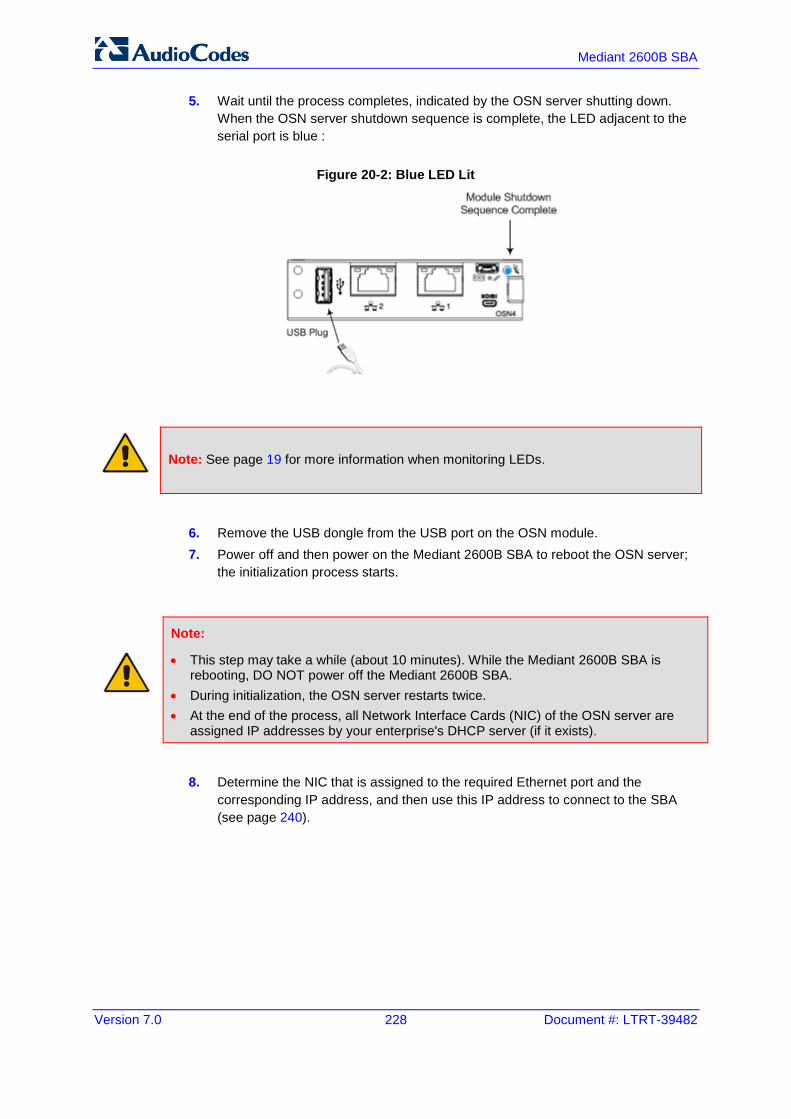
Version 7.0 228 Document #: LTRT-39482
Mediant 2600B SBA
5. Wait until the process completes, indicated by the OSN server shutting down. When the OSN server shutdown sequence is complete, the LED adjacent to the serial port is blue :
Figure 20-2: Blue LED Lit
Note: See page 19 for more information when monitoring LEDs.
6. Remove the USB dongle from the USB port on the OSN module. 7. Power off and then power on the Mediant 2600B SBA to reboot the OSN server;
the initialization process starts.
Note:
• This step may take a while (about 10 minutes). While the Mediant 2600B SBA is rebooting, DO NOT power off the Mediant 2600B SBA.
• During initialization, the OSN server restarts twice. • At the end of the process, all Network Interface Cards (NIC) of the OSN server are
assigned IP addresses by your enterprise's DHCP server (if it exists).
8. Determine the NIC that is assigned to the required Ethernet port and the corresponding IP address, and then use this IP address to connect to the SBA (see page 240).

Version 7.0 229 Skype for Business
Installation & Maintenance Manual 20. SBA Upgrade and Recovery
20.2 Starting Process with Online Monitoring using EMS You can monitor the SBA upgrade and recovery process using Emergency Management Services (EMS). EMS is a technology that supports remote management and system recovery for servers that are not accessible through an in-band connection. An in-band connection is a connection between two computers that relies on a standard network such as a LAN or the 'Internet' 'http://www.techhead.co.uk/emergency-management-services-ems-connection-detected \t undefined', and on standard remote administration tools such as Remote Desktop or Telnet. You can use this type of connection to remotely manage computers only if both the local and remote computers are in a functional state and accessible on the network. EMS redirects text output to the out-of-band connection. An out-of-band connection is a non-standard connection between two computers such as a serial port connection, and is useful when a remote server cannot access the network or is not fully functional. EMS provides a command-line environment for managing a server through the out-of-band port. The capability of redirecting text output is also Skype for Business console redirection.
Note: For the Mediant 2600B SBA OSN serial interface port (micro-USB) to be operational, you must download a special USB driver from the Internet. Download this driver at:
http://www.silabs.com/products/mcu/pages/usbtouartbridgevcpdrivers.aspx http:/www.silabs.com/products/mcu/pages/usbtouartbridgevcpdrivers.aspx
To monitor SBA upgrade and recovery using EMS:
1. Open (using a text editor such as Notepad) the RecoveryUtil.ini file and then set the RecoveryStartType parameter to 1, as shown below:
[Execution] RecoveryStartType= 1
2. Save and close the RecoveryUtil.ini file. Do one of the following:
3. Connect a serial cable with a micro-USB connector on one end, to the serial port (labeled IOIOI) on the OSN4 module.

Version 7.0 230 Document #: LTRT-39482
Mediant 2600B SBA
4. Connect the other end of the cable to the COM port on your computer.
Figure 20-3: Cabling OSN4 Module for Serial Communication
Note: For the Mediant 2600B SBA OSN serial interface port (micro-USB) to be operational, you must download a special USB driver from the Internet. Download this driver at http://www.silabs.com/products/mcu/pages/usbtouartbridgevcpdrivers.aspx http:/www.silabs.com/products/mcu/pages/usbtouartbridgevcpdrivers.aspx
5. Establish a serial communication session with the following port settings:
• Bits per second: 115200
• Data bits: 8
• Parity: None
• Stop bits: 1
• Flow control: None 6. Plug the USB dongle into the USB port on the OSN module (see figures below).

Version 7.0 231 Skype for Business
Installation & Maintenance Manual 20. SBA Upgrade and Recovery
7. Power off and then power on Mediant 2600B SBA to reboot the OSN server; during reboot, from the USB in the terminal window, the following message is displayed: "Windows is loading files…", as shown in the figure below.
Figure 20-4: Windows Loading Files
In a few moments, the special administration console (SAC) prompt appears and the following message is displayed: "Computer is booting. SAC is started and initialized."
8. Wait for the next message: "The CMD command is now available.", as shown in the figure below.

Version 7.0 232 Document #: LTRT-39482
Mediant 2600B SBA
Figure 20-5: SAC Started
9. Start the command-line console, by typing the following:
SAC> cmd
10. When the message, "A new channel has been created" is displayed, type the following command:
SAC> ch –si 0001

Version 7.0 233 Skype for Business
Installation & Maintenance Manual 20. SBA Upgrade and Recovery
where 0001 is the number of the created channel.
Figure 20-6: SAC Initiated

Version 7.0 234 Document #: LTRT-39482
Mediant 2600B SBA
The command console starts. When the command console is ready, the following is displayed:
Figure 20-7: Hyper Terminal
11. Press the <Enter> key to continue. 12. When the X:\windows\system32 prompt appears, type the following command:
X:\windows\system32>gorecover

Version 7.0 235 Skype for Business
Installation & Maintenance Manual 20. SBA Upgrade and Recovery
Figure 20-8: Gorecover
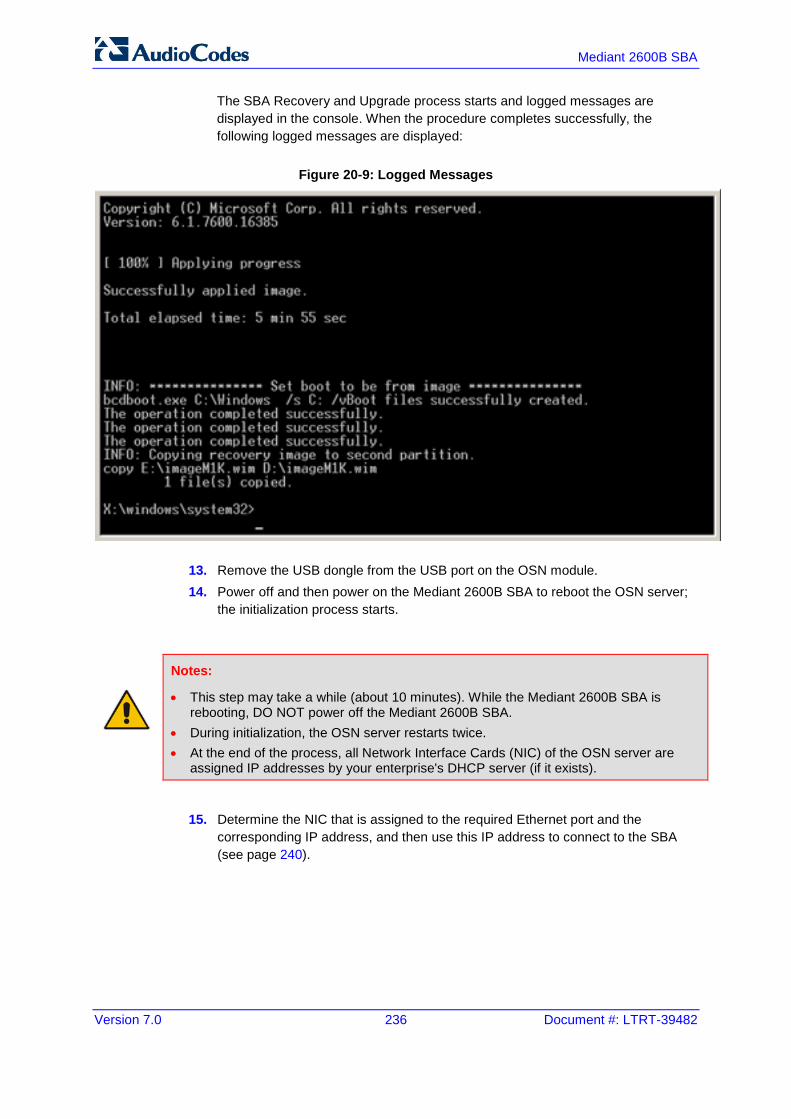
Version 7.0 236 Document #: LTRT-39482
Mediant 2600B SBA
The SBA Recovery and Upgrade process starts and logged messages are displayed in the console. When the procedure completes successfully, the following logged messages are displayed:
Figure 20-9: Logged Messages
13. Remove the USB dongle from the USB port on the OSN module. 14. Power off and then power on the Mediant 2600B SBA to reboot the OSN server;
the initialization process starts.
Notes:
• This step may take a while (about 10 minutes). While the Mediant 2600B SBA is rebooting, DO NOT power off the Mediant 2600B SBA.
• During initialization, the OSN server restarts twice. • At the end of the process, all Network Interface Cards (NIC) of the OSN server are
assigned IP addresses by your enterprise's DHCP server (if it exists).
15. Determine the NIC that is assigned to the required Ethernet port and the corresponding IP address, and then use this IP address to connect to the SBA (see page 240).

Version 7.0 237 Skype for Business
Installation & Maintenance Manual 20. SBA Upgrade and Recovery
20.3 Starting Process with Online Monitoring using Monitor You can monitor the SBA upgrade and recovery process for the OSN4 server using a VGA monitor.
To monitor SBA upgrade and recovery using monitor:
1. Open (using a text editor such as Notepad) the RecoveryUtil.ini file and then do the following:
• Set the 'RecoveryStartType' parameter to 0, in order to start the process automatically when Windows PE starts.
• Set the 'OnExit' parameter to 2 so that the OSN server shuts down upon SBA upgrade and recovery completion.
[Execution] RecoveryStartType= 0 [Execution] OnExit = 2
2. Save and close the RecoveryUtil.ini file. 3. Connect a USB hub to the USB port located on the OSN4 module, and then
connect the USB hub to the following computer peripherals:
• Mouse
• Keyboard
• USB storage device containing the operating system installation files (disk-on-key or external CD-ROM or DVD-ROM drive)

Version 7.0 238 Document #: LTRT-39482
Mediant 2600B SBA
4. Using the supplied MINI HDMI TO HDMI 1.5m cable, connect the Micro HDMI port on the OSN module using a Type-D male connector and connect the other end to the HDMI port on the monitor using a Mini HDMI connector (for HDMI connector cable pinouts, see Section 3.1.3).
Figure 20-10: Cabling OSN4 Module for Installing Operating System
Table 20-1: HDMI Type-D Connector Pinouts
Pin Signal
3 TMDS Data2+
4 TMDS Data2 Shield
5 TMDS Data2-
6 TMDS Data1+
7 TMDS Data1 Shield
8 TMDS Data1-
9 TMDS Data0+
10 TMDS Data0 Shield
11 TMDS Data0-
12 TMDS Clock+
13 TMDS Clock Shield
14 TMDS Clock-
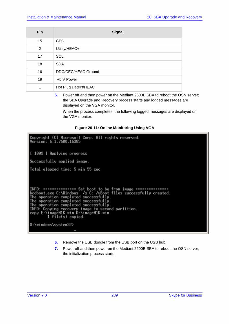
Version 7.0 239 Skype for Business
Installation & Maintenance Manual 20. SBA Upgrade and Recovery
Pin Signal
15 CEC
2 Utility/HEAC+
17 SCL
18 SDA
16 DDC/CEC/HEAC Ground
19 +5 V Power
1 Hot Plug Detect/HEAC
5. Power off and then power on the Mediant 2600B SBA to reboot the OSN server; the SBA Upgrade and Recovery process starts and logged messages are displayed on the VGA monitor. When the process completes, the following logged messages are displayed on the VGA monitor:
Figure 20-11: Online Monitoring Using VGA
6. Remove the USB dongle from the USB port on the USB hub. 7. Power off and then power on the Mediant 2600B SBA to reboot the OSN server;
the initialization process starts.

Version 7.0 240 Document #: LTRT-39482
Mediant 2600B SBA
Note:
• This step may take a while (about 10 minutes). While the Mediant 2600B SBA is rebooting, DO NOT power off the Mediant 2600B SBA.
• During initialization, the OSN server restarts twice. • At the end of the process, all Network Interface Cards (NIC) of the OSN server are
assigned IP addresses by your enterprise's DHCP server (if it exists).
8. Determine the NIC that is assigned to the required Ethernet port and the corresponding IP address, and then use this IP address to connect to the SBA (see page 240).
20.4 Acquiring an IP Address Once the OSN server has successfully rebooted, you need to identify the NIC corresponding to the Ethernet port. All Network Interface Cards (NIC) are assigned IP addresses by your enterprise's DHCP server (if it exists). If you are not using a DHCP server, you can assign a static IP address to this NIC.
Note: If the SBA was recovered or upgraded using the AudioCodes Upgrade and Recovery Upgrade and Recovery USB dongle, the IP address of the OSN server is received from the DHCP server and therefore, the default IP address is no longer applicable.
To acquire an IP address:
1. Do one of the following:
• If you are connecting to the network through the internal NIC: Connect the first Ethernet LAN port on the front panel of the device directly to the network using a straight-through Ethernet cable.
Figure 20-12: Connecting Mediant 2600B SBA LAN Port on SBC Module (Front Panel)

Version 7.0 241 Skype for Business
Installation & Maintenance Manual 20. SBA Upgrade and Recovery
• If you are connecting to the network through the external NIC: Connect one of the Ethernet LAN ports (1 or 2) on the OSN module to the network.
Figure 20-13: Cabling OSN4 Module to Network
2. If you have an HDMI monitor connected, do the following (otherwise, skip to Step 3):
• For connecting to the network via the internal NIC: a. If you have a DHCP server in your network, the internal NIC should be
identified by a displayed IP address (the two external Ethernet ports should be displayed as "Disconnected"). If you do not have a DHCP server in your network, define a static IP address.
b. Skip to Step 9.
• For connecting to the network via the external NIC: a. Determine the NIC used for the Ethernet LAN port, by removing the
network cable from the Ethernet port and viewing on the monitor that the NIC (ID) has changed to "Disconnected". This is the NIC corresponding to the Ethernet LAN port.
b. Reconnect the network cable and then do one of the following: If you have a DHCP server in your network, note the IP address
assigned to the Ethernet LAN port. If you are not using a DHCP server, then assign a static IP address
to the NIC of the Ethernet LAN port. c. Skip to Step 9.

Version 7.0 242 Document #: LTRT-39482
Mediant 2600B SBA
3. Connect a serial cable with a micro-USB connector on one end, to the serial port (labeled IOIOI) on the OSN4 module. Connect the other end of the cable to the COM port on your computer.
Figure 20-14: Cabling OSN4 Module for Serial Communication
Note: For the Mediant 2600B SBA OSN serial interface port (micro-USB) to be operational, you must download a special USB driver from the Internet. Download this driver at http://www.silabs.com/products/mcu/pages/usbtouartbridgevcpdrivers.aspx
http:/www.silabs.com/products/mcu/pages/usbtouartbridgevcpdrivers.aspx
4. Establish serial communication with the OSN server through a terminal emulation program (such as HyperTerminal), using the following serial communication settings:
• Baud Rate: 115200 (bits per second)
• Data Bits: 8
• Parity: None
• Stop Bits: 1
• Flow Control: None 5. Press Enter; the Serial Console prompt is displayed:
SAC>
6. Type the following to view all the NIC addresses:
SAC>i
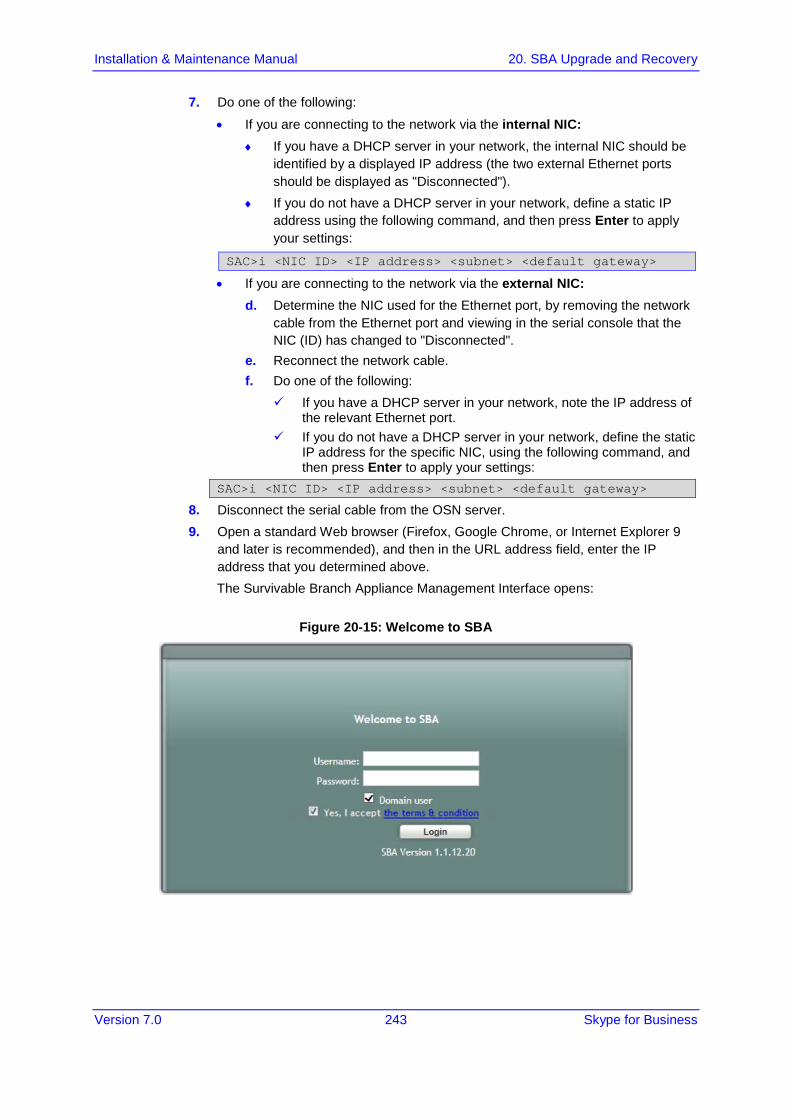
Version 7.0 243 Skype for Business
Installation & Maintenance Manual 20. SBA Upgrade and Recovery
7. Do one of the following:
• If you are connecting to the network via the internal NIC: ♦ If you have a DHCP server in your network, the internal NIC should be
identified by a displayed IP address (the two external Ethernet ports should be displayed as "Disconnected").
♦ If you do not have a DHCP server in your network, define a static IP address using the following command, and then press Enter to apply your settings:
SAC>i <NIC ID> <IP address> <subnet> <default gateway>
• If you are connecting to the network via the external NIC: d. Determine the NIC used for the Ethernet port, by removing the network
cable from the Ethernet port and viewing in the serial console that the NIC (ID) has changed to "Disconnected".
e. Reconnect the network cable. f. Do one of the following:
If you have a DHCP server in your network, note the IP address of the relevant Ethernet port.
If you do not have a DHCP server in your network, define the static IP address for the specific NIC, using the following command, and then press Enter to apply your settings:
SAC>i <NIC ID> <IP address> <subnet> <default gateway>
8. Disconnect the serial cable from the OSN server. 9. Open a standard Web browser (Firefox, Google Chrome, or Internet Explorer 9
and later is recommended), and then in the URL address field, enter the IP address that you determined above. The Survivable Branch Appliance Management Interface opens:
Figure 20-15: Welcome to SBA

Version 7.0 244 Document #: LTRT-39482
Mediant 2600B SBA
10. Log in with the default username ("Administrator") and password ("Pass123"), Select the "Yes, I accept the term and condition" checkbox and then click Login; the Home screen appears:
Figure 20-16: SBA Home Screen
11. Change the default IP address of the SBA Management Interface to suit your network environment (see ' Step 1: Define IP Settings') on page 80.

Part VIII Appendix


Version 7.0 247 Skype for Business
Installation & Maintenance Manual A. SBA Security Default Template
A SBA Security Default Template This appendix describes the AudioCodes provided default SBA security template (configured in Section 'Apply No Policy' on page 123). The Microsoft SCW security configuration database utility was used to prepare this template. This utility contains information on the following:
Server roles. See Section .'Server Roles' on page 247
Client features. See Section 'Client Features' on page 249
Administration and other options. See Section 'Administration and Other Options' on page 250
Services. See Section 'Services' on page 251
Firewall rules. See Section 'Firewall Rules' on page 272
A.1 Server Roles Each server role can be in one the following possible status:
Installed and enabled
Installed and disabled
Not installed and disabled
The following list details the server roles which must be installed and enabled on the SBA. The SCW uses the server role information to enable services and open ports in the local firewall.
Table A-1: Server Roles
Server Role Description
Application Server – Application Server Foundation
Application Server Foundation provides technologies for deploying and managing .NET Framework 3.0 applications. These technologies include Windows Presentation Foundation (WPF), Windows Communication Foundation (WCF), and Windows Workflow Foundation (WF). Application Server Foundation provides the means for delivering managed-code applications with seamless user experiences, secure communication, and the ability to model a range of business processes.
Application Server – Message Queuing Activation
Message Queuing Activation supports process activation via Message Queuing. Applications that use Message Queuing Activation can start and stop dynamically in response to work items that arrive over the network via Message Queuing.
Application Server – Named Pipes Activation
Named Pipes Activation supports process activation via named pipes. Applications that use Named Pipes Activation can start and stop dynamically in response to work items that arrive over the network via named pipes.

Version 7.0 248 Document #: LTRT-39482
Mediant 2600B SBA
Server Role Description
Application Server – TCP Activation
TCP Activation supports process activation via TCP. Applications that use TCP Activation can start and stop dynamically in response to work items that arrive over the network via TCP.
ASP.NET State Service The ASP.NET state service stores session state out of process from ASP.NET applications. It ensures that session state is preserved if an ASP.NET application is restarted and also makes session state available to multiple ASP.NET applications running in a Web farm.
Distributed Transactions The middle-tier application server can coordinate or participate in distributed transactions.
File Server A file server shares and stores files for users or applications.
Internet Printing Internet Printing creates a Web site where users can manage print jobs on the server. It also enables users who have Internet Printing Client installed to use a Web browser to connect and print to shared printers on this server by using the Internet Printing Protocol (IPP).
Message Queuing Server
Message Queuing Server provides guaranteed message delivery, efficient routing, security, and priority-based messaging. It can be used to implement solutions for both asynchronous and synchronous messaging scenarios.
Microsoft iSCSI Initiator Service
Manages Internet SCSI (iSCSI) sessions from this computer to remote iSCSI target devices. If this service is stopped, this computer will not be able to login or access iSCSI targets. If this service is disabled, any services that explicitly depend on it will fail to start.
Middle Tier Application Server (COM +/DTC)
A Middle-tier application server provides the core technologies required to configure, deploy, and manage distributed, transactional, or multi-tiered applications.
Print Server A print server provides and manages access to network printers and printer drivers so that network clients can submit print jobs to network printers.
Remote COM+ COM+ provides an enterprise development environment, based on the Microsoft Component Object Model (COM), for creating component-based, distributed applications. It also provides you with the tools to create transactional, multitier applications.
Remote SCW Configuration and Analysis
The server can be remotely configured, analyzed, or rolled back using the Security Configuration Wizard (SCW) user interface or command line tool.
Shadow Copies of Shared Folders
Shadow Copies of Shared Folders provides point-in-time copies of files that are located on shared resources, such as a file server, so that users can quickly retrieve previous versions of files.
SMTP Trap Server An SNMP trap server receives Simple Network Management Protocol (SNMP) traps from SNMP servers.
Volume Shadow Copy Manages and implements the backup infrastructure including shadow copies. If this service is disabled shadow copy creation and backup jobs will fail and any services that explicitly depend on it will fail to start.

Version 7.0 249 Skype for Business
Installation & Maintenance Manual A. SBA Security Default Template
Server Role Description
Web Server Web Server provides support for HTML Web sites and optional support for ASP.NET, ASP, and Web Server extensions. You can use the Web Server to host an internal or external Web site or to provide an environment for developers to create Web-based applications.
Window Event Collector Service
This service manages persistent subscriptions to events from remote sources that support WS-Management protocol. This includes Windows Vista event logs, hardware and IPMI-enabled event sources. The service stores forwarded events in a local Event Log. If this service is stopped or disabled event subscriptions cannot be created and forwarded events cannot be accepted.
Windows Process Activation Service
The Windows Process Activation Service (WAS) provides process activation, resource management and health management services for message-activated applications.
Windows Remote management (WS-Mangement)
The Windows Remote Management Service provides firewall-friendly remote administration using Web Services.
A.2 Client Features Servers also act as clients to other servers. Each client feature can be in one the following possible status:
Installed and enabled
Installed and disabled
Not installed and disabled
The following list details only the client features that must be installed and enabled on the SBA.
Table A-2: Client Features
Client Feature Description
Background Intelligent Transfer Service (BITS) Transfers files in the background using idle network bandwidth.
DNS Client DNS clients, also known as resolvers, use the DNS (Domain Name System) protocol to send queries to DNS Servers to lookup the DNS name of a computer and retrieve information associated with the computer, such as its IP address or other services it provides. This process is called name resolution.
Domain Member A domain member is a computer that is joined to an Active Directory domain.
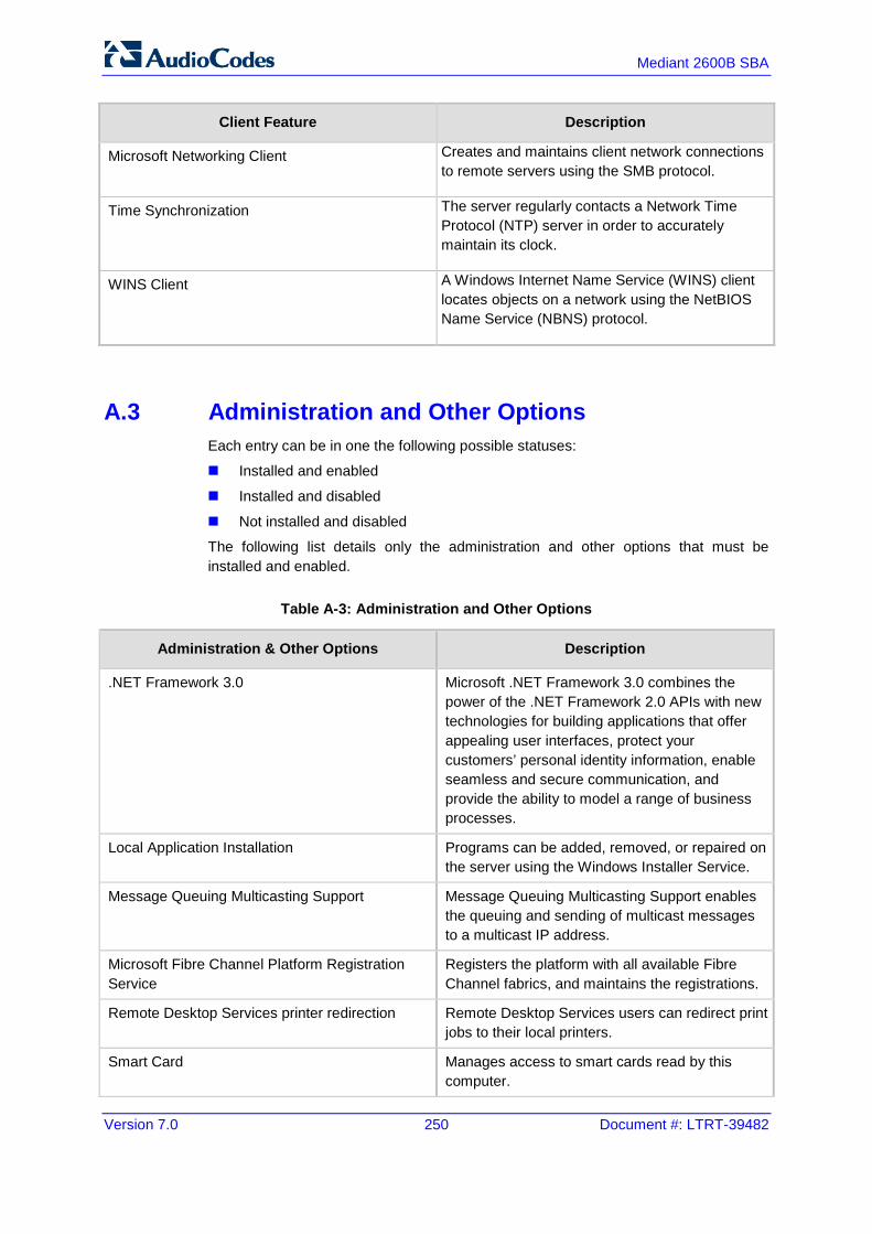
Version 7.0 250 Document #: LTRT-39482
Mediant 2600B SBA
Client Feature Description
Microsoft Networking Client Creates and maintains client network connections to remote servers using the SMB protocol.
Time Synchronization The server regularly contacts a Network Time Protocol (NTP) server in order to accurately maintain its clock.
WINS Client A Windows Internet Name Service (WINS) client locates objects on a network using the NetBIOS Name Service (NBNS) protocol.
A.3 Administration and Other Options Each entry can be in one the following possible statuses:
Installed and enabled
Installed and disabled
Not installed and disabled
The following list details only the administration and other options that must be installed and enabled.
Table A-3: Administration and Other Options
Administration & Other Options Description
.NET Framework 3.0 Microsoft .NET Framework 3.0 combines the power of the .NET Framework 2.0 APIs with new technologies for building applications that offer appealing user interfaces, protect your customers’ personal identity information, enable seamless and secure communication, and provide the ability to model a range of business processes.
Local Application Installation Programs can be added, removed, or repaired on the server using the Windows Installer Service.
Message Queuing Multicasting Support Message Queuing Multicasting Support enables the queuing and sending of multicast messages to a multicast IP address.
Microsoft Fibre Channel Platform Registration Service
Registers the platform with all available Fibre Channel fabrics, and maintains the registrations.
Remote Desktop Services printer redirection Remote Desktop Services users can redirect print jobs to their local printers.
Smart Card Manages access to smart cards read by this computer.
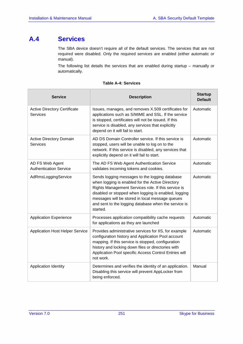
Version 7.0 251 Skype for Business
Installation & Maintenance Manual A. SBA Security Default Template
A.4 Services The SBA device doesn’t require all of the default services. The services that are not required were disabled. Only the required services are enabled (either automatic or manual). The following list details the services that are enabled during startup – manually or automatically.
Table A-4: Services
Service Description Startup Default
Active Directory Certificate Services
Issues, manages, and removes X.509 certificates for applications such as S/MIME and SSL. If the service is stopped, certificates will not be issued. If this service is disabled, any services that explicitly depend on it will fail to start.
Automatic
Active Directory Domain Services
AD DS Domain Controller service. If this service is stopped, users will be unable to log on to the network. If this service is disabled, any services that explicitly depend on it will fail to start.
Automatic
AD FS Web Agent Authentication Service
The AD FS Web Agent Authentication Service validates incoming tokens and cookies.
Automatic
AdRmsLoggingService Sends logging messages to the logging database when logging is enabled for the Active Directory Rights Management Services role. If this service is disabled or stopped when logging is enabled, logging messages will be stored in local message queues and sent to the logging database when the service is started.
Automatic
Application Experience Processes application compatibility cache requests for applications as they are launched
Automatic
Application Host Helper Service Provides administrative services for IIS, for example configuration history and Application Pool account mapping. If this service is stopped, configuration history and locking down files or directories with Application Pool specific Access Control Entries will not work.
Automatic
Application Identity Determines and verifies the identity of an application. Disabling this service will prevent AppLocker from being enforced.
Manual

Version 7.0 252 Document #: LTRT-39482
Mediant 2600B SBA
Service Description Startup Default
Application Information Facilitates the running of interactive applications with additional administrative privileges. If this service is stopped, users will be unable to launch applications with the additional administrative privileges they may require to perform desired user tasks.
Manual
Application Layer Gateway Service
Provides support for 3rd party protocol plug-ins for Internet Connection Sharing
Manual
Application Management Processes installation, removal, and enumeration requests for software deployed through the Group Policy. If this service is stopped, users will be unable to install, remove, or enumerate software deployed through the Group Policy. If this service is disabled, any services that explicitly depend on it will fail to start.
Manual
ASP.NET State Service Provides support for out-of-process session states for ASP.NET. If this service is stopped, out-of-process requests will not be processed. If this service is disabled, any services that explicitly depend on it will fail to start.
Automatic
AudioEndpointBuilder Manages audio devices for the Windows Audio service. If this service is stopped, audio devices and effects will not function properly. If this service is disabled, any services that explicitly depend on it will fail to start.
Manual
Audiosrv Manages audio for Windows-based programs. If this service is stopped, audio devices and effects will not function properly. If this service is disabled, any services that explicitly depend on it will fail to start.
Manual
Background Intelligent Transfer Service
Transfers files in the background using idle network bandwidth. If the service is disabled, then any applications that depend on BITS, such as Windows Update or MSN Explorer, will be unable to automatically download programs and other information.
Automatic
Base Filtering Engine The Base Filtering Engine (BFE) is a service that manages firewall and Internet Protocol security (IPsec) policies and implements user mode filtering. Stopping or disabling the BFE service will significantly reduce the security of the system. It will also result in unpredictable behavior in IPsec management and firewall applications.
Automatic
Block Level Backup Engine Service
Engine to perform block level backup and recovery of data.
Manual

Version 7.0 253 Skype for Business
Installation & Maintenance Manual A. SBA Security Default Template
Service Description Startup Default
BOAService _ Automatic
Certificate Propagation Copies user certificates and root certificates from smart cards into the current user's certificate store, detects when a smart card is inserted into a smart card reader, and, if required, installs the smart card Plug and Play minidriver.
Automatic
Client for NFS Enables this computer to access files on NFS shares. Automatic
clr_optimization_v2.0.50727_I64
clr_optimization_v2.0.50727_I64 Manual
Cluster Service Enables servers to work together as a cluster to keep server-based applications highly available, regardless of individual component failures. If this service is stopped, clustering will be unavailable. If this service is disabled, any services that explicitly depend on it will fail to start.
Automatic
CNG Key Isolation The CNG key isolation service is hosted in the LSA process. The service provides key process isolation to private keys and associated cryptographic operations as required by the Common Criteria. The service stores and uses long-lived keys in a secure process complying with Common Criteria requirements.
Manual
COM+ Event System Supports System Event Notification Service (SENS), which provides automatic distribution of events to subscribing Component Object Model (COM) components. If the service is stopped, SENS will close and will not be able to provide logon and logoff notifications. If this service is disabled, any services that explicitly depend on it will fail to start.
Automatic
COM+ System Application Manages the configuration and tracking of Component Object Model (COM)+-based components. If the service is stopped, most COM+-based components will not function properly. If this service is disabled, any services that explicitly depend on it will fail to start.
Manual
Computer Browser Maintains an updated list of computers on the network and supplies this list to computers designated as browsers. If this service is stopped, this list will not be updated or maintained. If this service is disabled, any services that explicitly depend on it will fail to start.
Automatic
Credential Manager Provides secure storage and retrieval of credentials to users, applications and security service packages.
Manual

Version 7.0 254 Document #: LTRT-39482
Mediant 2600B SBA
Service Description Startup Default
Cryptographic Services Provides four management services: Catalog Database Service, which confirms the signatures of Windows files and allows new programs to be installed; Protected Root Service, which adds and removes Trusted Root Certification Authority certificates from this computer; Automatic Root Certificate Update Service, which retrieves root certificates from Windows Update and enable scenarios such as SSL; and Key Service, which helps enroll this computer for certificates. If this service is stopped, these management services will not function properly. If this service is disabled, any services that explicitly depend on it will fail to start.
Automatic
DCOM Server Process Launcher
The DCOMLAUNCH service launches COM and DCOM servers in response to object activation requests. If this service is stopped or disabled, programs using COM or DCOM will not function properly. It is strongly recommended that you have the DCOMLAUNCH service up and running.
Automatic
Desktop Window Manager Session Manager
Provides Desktop Window Manager startup and maintenance services
Automatic
DFS Namespace Integrates disparate file shares into a single, logical namespace and manages these logical volumes.
Automatic
DFS Replication Replicates files among multiple PCs keeping them in sync. On the client, it is used to roam folders between PCs and on the server, it is used to provide high availability and local access across a wide area network (WAN). If the service is stopped, file replication does not occur, and the files on the server become out-of-date. If the service is disabled, any services that explicitly depend on it will not start.
Automatic
DHCP Client Registers and updates IP addresses and DNS records for this computer. If this service is stopped, this computer will not receive dynamic IP addresses and DNS updates. If this service is disabled, any services that explicitly depend on it will fail to start.
Automatic
DHCP Server Performs TCP/IP configuration for DHCP clients, including dynamic assignments of IP addresses, specification of the WINS and DNS servers, and connection-specific DNS names. If this service is stopped, the DHCP server will not perform TCP/IP configuration for clients. If this service is disabled, any services that explicitly depend on it will fail to start.
Automatic
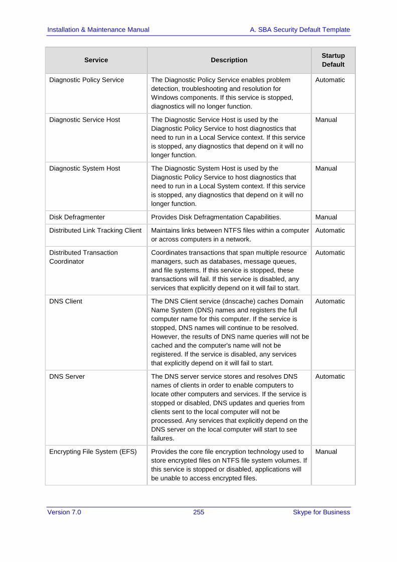
Version 7.0 255 Skype for Business
Installation & Maintenance Manual A. SBA Security Default Template
Service Description Startup Default
Diagnostic Policy Service The Diagnostic Policy Service enables problem detection, troubleshooting and resolution for Windows components. If this service is stopped, diagnostics will no longer function.
Automatic
Diagnostic Service Host The Diagnostic Service Host is used by the Diagnostic Policy Service to host diagnostics that need to run in a Local Service context. If this service is stopped, any diagnostics that depend on it will no longer function.
Manual
Diagnostic System Host The Diagnostic System Host is used by the Diagnostic Policy Service to host diagnostics that need to run in a Local System context. If this service is stopped, any diagnostics that depend on it will no longer function.
Manual
Disk Defragmenter Provides Disk Defragmentation Capabilities. Manual
Distributed Link Tracking Client Maintains links between NTFS files within a computer or across computers in a network.
Automatic
Distributed Transaction Coordinator
Coordinates transactions that span multiple resource managers, such as databases, message queues, and file systems. If this service is stopped, these transactions will fail. If this service is disabled, any services that explicitly depend on it will fail to start.
Automatic
DNS Client The DNS Client service (dnscache) caches Domain Name System (DNS) names and registers the full computer name for this computer. If the service is stopped, DNS names will continue to be resolved. However, the results of DNS name queries will not be cached and the computer's name will not be registered. If the service is disabled, any services that explicitly depend on it will fail to start.
Automatic
DNS Server The DNS server service stores and resolves DNS names of clients in order to enable computers to locate other computers and services. If the service is stopped or disabled, DNS updates and queries from clients sent to the local computer will not be processed. Any services that explicitly depend on the DNS server on the local computer will start to see failures.
Automatic
Encrypting File System (EFS) Provides the core file encryption technology used to store encrypted files on NTFS file system volumes. If this service is stopped or disabled, applications will be unable to access encrypted files.
Manual
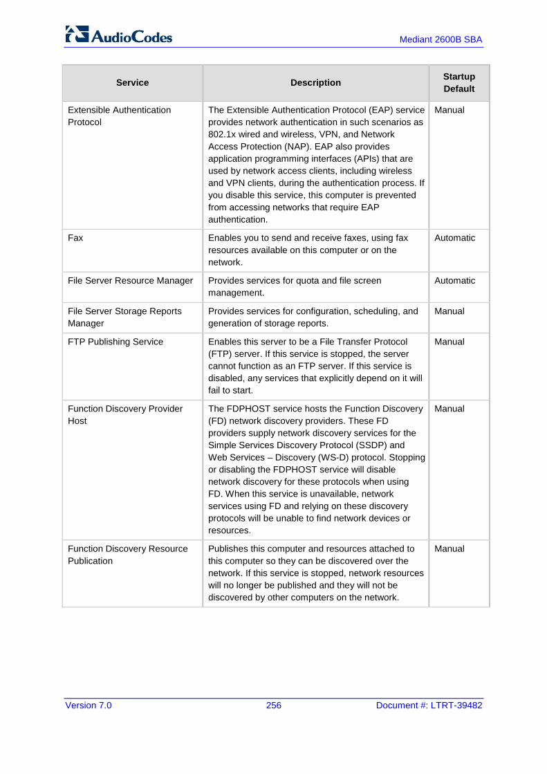
Version 7.0 256 Document #: LTRT-39482
Mediant 2600B SBA
Service Description Startup Default
Extensible Authentication Protocol
The Extensible Authentication Protocol (EAP) service provides network authentication in such scenarios as 802.1x wired and wireless, VPN, and Network Access Protection (NAP). EAP also provides application programming interfaces (APIs) that are used by network access clients, including wireless and VPN clients, during the authentication process. If you disable this service, this computer is prevented from accessing networks that require EAP authentication.
Manual
Fax Enables you to send and receive faxes, using fax resources available on this computer or on the network.
Automatic
File Server Resource Manager Provides services for quota and file screen management.
Automatic
File Server Storage Reports Manager
Provides services for configuration, scheduling, and generation of storage reports.
Manual
FTP Publishing Service Enables this server to be a File Transfer Protocol (FTP) server. If this service is stopped, the server cannot function as an FTP server. If this service is disabled, any services that explicitly depend on it will fail to start.
Manual
Function Discovery Provider Host
The FDPHOST service hosts the Function Discovery (FD) network discovery providers. These FD providers supply network discovery services for the Simple Services Discovery Protocol (SSDP) and Web Services – Discovery (WS-D) protocol. Stopping or disabling the FDPHOST service will disable network discovery for these protocols when using FD. When this service is unavailable, network services using FD and relying on these discovery protocols will be unable to find network devices or resources.
Manual
Function Discovery Resource Publication
Publishes this computer and resources attached to this computer so they can be discovered over the network. If this service is stopped, network resources will no longer be published and they will not be discovered by other computers on the network.
Manual
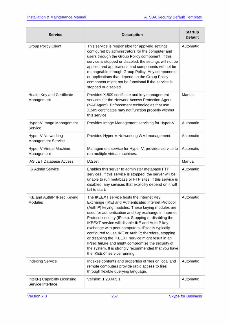
Version 7.0 257 Skype for Business
Installation & Maintenance Manual A. SBA Security Default Template
Service Description Startup Default
Group Policy Client This service is responsible for applying settings configured by administrators for the computer and users through the Group Policy component. If this service is stopped or disabled, the settings will not be applied and applications and components will not be manageable through Group Policy. Any components or applications that depend on the Group Policy component might not be functional if the service is stopped or disabled.
Automatic
Health Key and Certificate Management
Provides X.509 certificate and key management services for the Network Access Protection Agent (NAPAgent). Enforcement technologies that use X.509 certificates may not function properly without this service.
Manual
Hyper-V Image Management Service
Provides Image Management servicing for Hyper-V. Automatic
Hyper-V Networking Management Service
Provides Hyper-V Networking WMI management. Automatic
Hyper-V Virtual Machine Management
Management service for Hyper-V, provides service to run multiple virtual machines.
Automatic
IAS JET Database Access IASJet Manual
IIS Admin Service Enables this server to administer metabase FTP services. If this service is stopped, the server will be unable to run metabase or FTP sites. If this service is disabled, any services that explicitly depend on it will fail to start.
Automatic
IKE and AuthIP IPsec Keying Modules
The IKEEXT service hosts the Internet Key Exchange (IKE) and Authenticated Internet Protocol (AuthIP) keying modules. These keying modules are used for authentication and key exchange in Internet Protocol security (IPsec). Stopping or disabling the IKEEXT service will disable IKE and AuthIP key exchange with peer computers. IPsec is typically configured to use IKE or AuthIP; therefore, stopping or disabling the IKEEXT service might result in an IPsec failure and might compromise the security of the system. It is strongly recommended that you have the IKEEXT service running.
Automatic
Indexing Service Indexes contents and properties of files on local and remote computers provide rapid access to files through flexible querying language.
Automatic
Intel(R) Capability Licensing Service Interface
Version: 1.23.605.1 Automatic

Version 7.0 258 Document #: LTRT-39482
Mediant 2600B SBA
Service Description Startup Default
Intel(R) Dynamic Application Loader Host Interface Service
Intel(R) Dynamic Application Loader Host Interface Service - allows applications to access the local Intel (R) DAL.
Automatic
Intel(R) Management and Security Application Local Management Service
Allows applications to access the local Intel(R) Management and Security Application using its locally-available selected network interfaces.
Automatic
Intel(R) Management and Security Application User Notification Service
Intel(R) Management and Security Application User Notification Service - Updates the Windows Event Log with notifications of pre defined events received from the local Intel(R) Management and Security Application Device.
Automatic
Intel(R) PROSet Monitoring Service
The Intel(R) PROSet Monitoring Service actively monitors changes to the system and updates affected network devices to keep them running in optimal condition. Stopping this service may negatively affect the performance of the network devices on the system.
Automatic
Interactive Services Detection Enables user notification of user input for interactive services, which enables access to dialogs created by interactive services when they appear. If this service is stopped, notifications of new interactive service dialogs will no longer function and there may no longer be access to interactive service dialogs. If this service is disabled, both notifications of and access to new interactive service dialogs will no longer function.
Manual
Intersite Messaging Enables messages to be exchanged between computers running Windows Server sites. If this service is stopped, messages will not be exchanged, nor will site routing information be calculated for other services. If this service is disabled, any services that explicitly depend on it will fail to start.
Automatic
IP Helper Provides tunnel connectivity using IPv6 transition technologies (6to4, ISATAP, Port Proxy, and Teredo), and IP-HTTPS. If this service is stopped, the computer will not have the enhanced connectivity benefits that these technologies offer.
Automatic

Version 7.0 259 Skype for Business
Installation & Maintenance Manual A. SBA Security Default Template
Service Description Startup Default
IPsec Policy Agent Internet Protocol security (IPsec) supports network-level peer authentication, data origin authentication, data integrity, data confidentiality (encryption), and replay protection. This service enforces IPsec policies created through the IP Security Policies snap-in or the command-line tool "netsh ipsec". If you stop this service, you may experience network connectivity issues if your policy requires that connections use IPsec. Also,remote management of Windows Firewall is not available when this service is stopped.
Automatic
Kerberos Key Distribution Center
On domain controllers this service enables users to log on to the network using the Kerberos authentication protocol. If this service is stopped on a domain controller, users will be unable to log on to the network. If this service is disabled, any services that explicitly depend on it will fail to start.
Automatic
KtmRm for Distributed Transaction Coordinator
Coordinates transactions between the Distributed Transaction Coordinator (MSDTC) and the Kernel Transaction Manager (KTM). If it is not needed, it is recommended that this service remains stopped. If it is needed, both MSDTC and KTM will start this service automatically. If this service is disabled, any MSDTC transaction interacting with a Kernel Resource Manager will fail and any services that explicitly depend on it will fail to start.
Automatic
Link-Layer Topology Discovery Mapper
Creates a Network Map, consisting of PC and device topology (connectivity) information, and metadata describing each PC and device. If this service is disabled, the Network Map will not function properly.
Manual
Skype for Business Front-End Skype for Business Front-End Automatic
Skype for Business Mediation Skype for Business Mediation Automatic
Skype for Business Replica Replicator Agent
Skype for Business Replica Replicator Agent Automatic
Message Queuing Provides a messaging infrastructure and development tool for creating distributed messaging applications for Windows-based networks and programs. If this service is stopped, distributed messages will be unavailable. If this service is disabled, any services that explicitly depend on it will fail to start.
Automatic
Message Queuing Downlevel Client Support
Allows MSMQ 2.0 clients to access MSMQ Active Directory features
Automatic

Version 7.0 260 Document #: LTRT-39482
Mediant 2600B SBA
Service Description Startup Default
Message Queuing Triggers Provides rule-based monitoring of messages arriving in a Message Queuing queue and, when the conditions of a rule are satisfied, invokes a COM component or a stand-alone executable program to process the message.
Automatic
Microsoft .NET Framework NGEN v2.0.50727_X64
Microsoft .NET Framework NGEN Manual
Microsoft .NET Framework NGEN v2.0.50727_X86
Microsoft .NET Framework NGEN Manual
Microsoft Fibre Channel Platform Registration Service
Registers the platform with all available Fibre Channel fabrics, and maintains the registrations.
Automatic
Microsoft iSCSI Initiator Service Manages Internet SCSI (iSCSI) sessions from this computer to remote iSCSI target devices. If this service is stopped, this computer will not be able to login or access iSCSI targets. If this service is disabled, any services that explicitly depend on it will fail to start.
Manual
Microsoft iSNS Server Maintains a database of iSNS client registrations and notifies clients when changes are made to the database.
Automatic
Microsoft Software Shadow Copy Provider
Manages software-based volume shadow copies taken by the Volume Shadow Copy service. If this service is stopped, software-based volume shadow copies cannot be managed. If this service is disabled, any services that explicitly depend on it will fail to start.
Manual
Net.Msmq Listener Adapter Receives activation requests over the net.msmq and msmq.formatname protocols and passes them to the Windows Process Activation Service.
Automatic
Net.Pipe Listener Adapter Receives activation requests over the net.pipe protocol and passes them to the Windows Process Activation Service.
Automatic
Net.Tcp Listener Adapter Receives activation requests over the net.tcp protocol and passes them to the Windows Process Activation Service.
Automatic

Version 7.0 261 Skype for Business
Installation & Maintenance Manual A. SBA Security Default Template
Service Description Startup Default
Network Access Protection Agent
The Network Access Protection (NAP) agent service collects and manages health information for client computers on a network. Information collected by NAP agent is used to make sure that the client computer has the required software and settings. If a client computer is not compliant with health policy, it can be provided with restricted network access until its configuration is updated. Depending on the configuration of health policy, client computers might be automatically updated so that users quickly regain full network access without having to manually update their computer.
Manual
Network Connections Manages objects in the Network and Dial-Up Connections folder, in which you can view both local area network and remote connections.
Manual
Network List Service Identifies the networks to which the computer has connected, collects and stores properties for these networks, and notifies applications when these properties change.
Automatic
Network Location Awareness Collects and stores configuration information for the network and notifies programs when this information is modified. If this service is stopped, configuration information might be unavailable. If this service is disabled, any services that explicitly depend on it will fail to start.
Automatic
Network Policy Server Manages authentication, authorization, auditing and accounting for virtual private network (VPN), dial-up, 802.1x wireless or Ethernet switch connection attempts sent by access servers that are compatible with the IETF RADIUS protocol. If this service is stopped, users might be unable to obtain a VPN, dial-up, wireless, or Ethernet connection to the network. If this service is disabled, any services that explicitly depend on it will fail to start.
Automatic
Network Store Interface Service This service delivers network notifications (e.g. interface addition/deleting etc) to user mode clients. Stopping this service will cause loss of network connectivity. If this service is disabled, any other services that explicitly depend on this service will fail to start.
Automatic

Version 7.0 262 Document #: LTRT-39482
Mediant 2600B SBA
Service Description Startup Default
Online Responder Service Enables the Online Certificate Status Protocol (OCSP) services for a PKI based applications such as secure e-mail, smartcard logon, secure web servers. If this service is stopped or disabled then the revocation services may not be available thereby causing authentication or application failures.
Automatic
Peer Name Resolution Protocol Enables Serverless Peer Name Resolution over the Internet. If disabled, some Peer to Peer and Collaborative applications, such as Windows Meetings, may not function.
Manual
Peer Networking Identity Manager
Provides Identity service for Peer Networking. Manual
Performance Counter DLL Host Enables remote users and 64-bit processes to query performance counters provided by 32-bit DLLs. If this service is stopped, only local users and 32-bit processes will be able to query performance counters provided by 32-bit DLLs.
Manual
Performance Logs & Alerts Performance logs and alerts collect performance data from local or remote computers based on pre-configured schedule parameters, then writes the data to a log or triggers an alert. If this service is stopped, performance information will not be collected. If this service is disabled, any services that explicitly depend on it will fail to start.
Manual
Plug and Play Enables a computer to recognize and adapt to hardware changes with little or no user input. Stopping or disabling this service will result in system instability.
Automatic
PNRP Machine Name Publication Service
This service publishes a machine name using the Peer Name Resolution Protocol. Configuration is managed via the netsh context 'p2p pnrp peer'.
Manual
Portable Device Enumerator Service
Enforces group policy for removable mass-storage devices. Enables applications such as Windows Media Player and Image Import Wizard to transfer and synchronize content using removable mass-storage devices.
Manual
Power Manages power policy and power policy notification delivery.
Automatic
Print Spooler Loads files to memory for later printing. Automatic
Problem Reports and Solutions Control Panel Support
This service provides support for viewing, sending and deletion of system-level problem reports for the Problem Reports and Solutions control panel.
Manual

Version 7.0 263 Skype for Business
Installation & Maintenance Manual A. SBA Security Default Template
Service Description Startup Default
Protected Storage Provides protected storage for sensitive data, such as passwords, to prevent access by unauthorized services, processes, or users.
Manual
Quality Windows Audio Video Experience
Quality Windows Audio Video Experience (qWave) is a networking platform for Audio Video (AV) streaming applications on IP home networks. qWave enhances AV streaming performance and reliability by ensuring network quality-of-service (QoS) for AV applications. It provides mechanisms for admission control, run time monitoring and enforcement, application feedback, and traffic prioritization.
Manual
Remote Access Auto Connection Manager
Creates a connection to a remote network whenever a program references a remote DNS or NetBIOS name or address.
Manual
Remote Access Connection Manager
Manages dial-up and virtual private network (VPN) connections from this computer to the Internet or other remote networks. If this service is disabled, any services that explicitly depend on it will fail to start.
Manual
Remote Access Quarantine Agent
Removes validated remote access client from the quarantine network.
Manual
Remote Desktop Configuration Remote Desktop Configuration service (RDCS) is responsible for all Remote Desktop Services and Remote Desktop related configuration and session maintenance activities that require SYSTEM context. These include per-session temporary folders, RD themes, and RD certificates.
Automatic
Remote Desktop Gateway Provides secure remote connectivity to remote computers on your corporate network, from anywhere on the Internet. If this service is stopped, connections to remote computers cannot be made through this Remote Desktop Gateway server.
Automatic
Remote Desktop Licensing Provides registered licenses for Remote Desktop Services clients. If this service is stopped, the server will be unavailable to issue Remote Desktop Services client access licenses to clients when they are requested.
Automatic
Remote Desktop Services Allows users to connect interactively to a remote computer. Remote Desktop and Remote Desktop Session Host Server depend on this service. To prevent remote use of this computer, clear the checkboxes on the Remote tab of the System properties control panel item.
Automatic

Version 7.0 264 Document #: LTRT-39482
Mediant 2600B SBA
Service Description Startup Default
Remote Desktop Services UserMode Port Redirector
Allows the redirection of Printers/Drives/Ports for RDP connections.
Manual
Remote Desktop Services Connection Broker
Enables a user connection request to be routed to the appropriate Remote Desktop Session Host in a cluster. If this service is stopped, connection requests will be routed to the first available server.
Automatic
Remote Packet Capture Protocol v.0 (experimental)
Allows to capture traffic on this machine from a remote machine.
Manual
Remote Packet Capture Protocol v.0 (experimental)
Allows to capture traffic on this machine from a remote machine.
Manual
Remote Procedure Call (RPC) The RPCSS service is the Service Control Manager for COM and DCOM servers. It performs object activations requests, object exporter resolutions and distributed garbage collection for COM and DCOM servers. If this service is stopped or disabled, programs using COM or DCOM will not function properly. It is strongly recommended that you have the RPCSS service running.
Automatic
Remote Procedure Call (RPC) Locator
In Windows 2003 and earlier versions of Windows, the Remote Procedure Call (RPC) Locator service manages the RPC name service database. In Windows Vista and later versions of Windows, this service does not provide any functionality and is present for application compatibility.
Manual
Remote Registry Enables remote users to modify registry settings on this computer. If this service is stopped, the registry can be modified only by users on this computer. If this service is disabled, any services that explicitly depend on it will fail to start.
Automatic
Removable Storage Manages and catalogs removable media and operates automated removable media devices. If this service is stopped, programs that are dependent on Removable Storage, such as Backup and Remote Storage, will operate more slowly. If this service is disabled, any services that explicitly depend on it will fail to start.
Manual
Resultant Set of Policy Provider Provides a network service that processes requests to simulate application of Group Policy settings for a target user or computer in various situations and computes the Resultant Set of Policy settings.
Manual

Version 7.0 265 Skype for Business
Installation & Maintenance Manual A. SBA Security Default Template
Service Description Startup Default
Secondary Logon Enables starting processes under alternate credentials. If this service is stopped, this type of logon access will be unavailable. If this service is disabled, any services that explicitly depend on it will fail to start.
Automatic
Secure Socket Tunneling Protocol Service
Provides support for the Secure Socket Tunneling Protocol (SSTP) to connect to remote computers using VPN. If this service is disabled, users will not be able to use SSTP to access remote servers.
Manual
Security Accounts Manager The startup of this service signals other services that the Security Accounts Manager (SAM) is ready to accept requests. Disabling this service will prevent other services in the system from being notified when the SAM is ready, which may in turn cause those services to fail to start correctly. This service should not be disabled.
Automatic
Server Supports file, print, and named-pipe sharing over the network for this computer. If this service is stopped, these functions will be unavailable. If this service is disabled, any services that explicitly depend on it will fail to start.
Automatic
Server for NFS Enables a Windows based computer to act as an NFS Server.
Automatic
Shell Hardware Detection Provides notifications for AutoPlay hardware events. Automatic
Simple Mail Transfer Protocol (SMTP)
Transports electronic mail across the network. Manual
Simple TCP/IP Services Supports the following TCP/IP services: Character Generator, Daytime, Discard, Echo, and Quote of the Day.
Automatic
Smart Card Manages access to smart cards read by this computer. If this service is stopped, this computer will be unable to read smart cards. If this service is disabled, any services that explicitly depend on it will fail to start.
Automatic
SNMP Service Enables Simple Network Management Protocol (SNMP) requests to be processed by this computer. If this service is stopped, the computer will be unable to process SNMP requests.
Automatic

Version 7.0 266 Document #: LTRT-39482
Mediant 2600B SBA
Service Description Startup Default
SNMP Trap Receives trap messages generated by local or remote Simple Network Management Protocol (SNMP) agents and forwards the messages to SNMP management programs running on this computer. If this service is stopped, SNMP-based programs on this computer will not receive SNMP trap messages. If this service is disabled, any services that explicitly depend on it will fail to start.
Manual
Software Protection Enables the download, installation and enforcement of digital licenses for Windows and Windows applications. If the service is disabled, the operating system and licensed applications may run in a notification mode. It is strongly recommended that you not disable the Software Protection service.
Automatic
Special Administration Console Helper
Allows administrators to remotely access a command prompt using Emergency Management Services.
Manual
SPP Notification Service Provides Software Licensing activation and notification
Manual
SQL Active Directory Helper Service
Enables integration with Active Directories Automatic
SQL Server (RTCLOCAL) Provides storage, processing and controlled access of data, and rapid transaction processing.
Automatic
SQL Server Agent (RTCLOCAL)
Executes jobs, monitors SQL Server, fires alerts, and allows automation of some administrative tasks.
Automatic
SQL Server Browser Provides SQL Server connection information to client computers.
Automatic
SQL Server VSS Writer Provides the interface to backup/restore Windows internal database through the Windows VSS infrastructure.
Automatic
SSDP Discovery Discovers networked devices and services that use the SSDP discovery protocol, such as UPnP devices. Also announces SSDP devices and services running on the local computer. If this service is stopped, SSDP-based devices will not be discovered. If this service is disabled, any services that explicitly depend on it will fail to start.
Manual
System Event Notification Service
Monitors system events and notifies subscribers to COM+ Event System of these events.
Automatic

Version 7.0 267 Skype for Business
Installation & Maintenance Manual A. SBA Security Default Template
Service Description Startup Default
Task Scheduler Enables a user to configure and schedule automated tasks on this computer. The service also hosts multiple Windows system-critical tasks. If this service is stopped or disabled, these tasks will not be run at their scheduled times. If this service is disabled, any services that explicitly depend on it will fail to start.
Automatic
TCP/IP NetBIOS Helper Provides support for the NetBIOS over TCP/IP (NetBT) service and NetBIOS name resolution for clients on the network, therefore enabling users to share files, print, and log on to the network. If this service is stopped, these functions might be unavailable. If this service is disabled, any services that explicitly depend on it will fail to start.
Automatic
TCP/IP Print Server Enables TCP/IP-based printing using the Line Printer Daemon protocol. If this service is stopped, TCP/IP-based printing will be unavailable. If this service is disabled, any services that explicitly depend on it will fail to start.
Automatic
Telephony Provides Telephony API (TAPI) support for programs that control telephony devices on the local computer and, through the LAN, on servers that are also running the service.
Manual
TPM Base Services Enables access to the Trusted Platform Module (TPM), which provides hardware-based cryptographic services to system components and applications. If this service is stopped or disabled, applications will be unable to use keys protected by the TPM.
Manual
UPnP Device Host Allows UPnP devices to be hosted on this computer. If this service is stopped, any hosted UPnP devices will stop functioning and no additional hosted devices can be added. If this service is disabled, any services that explicitly depend on it will fail to start.
Automatic
User Profile Service This service is responsible for loading and unloading user profiles. If this service is stopped or disabled, users will no longer be able to successfully logon or logoff, applications may have problems accessing users' data, and components registered to receive profile event notifications will not receive them.
Automatic
Virtual Disk Provides management services for disks, volumes, file systems, and storage arrays.
Manual
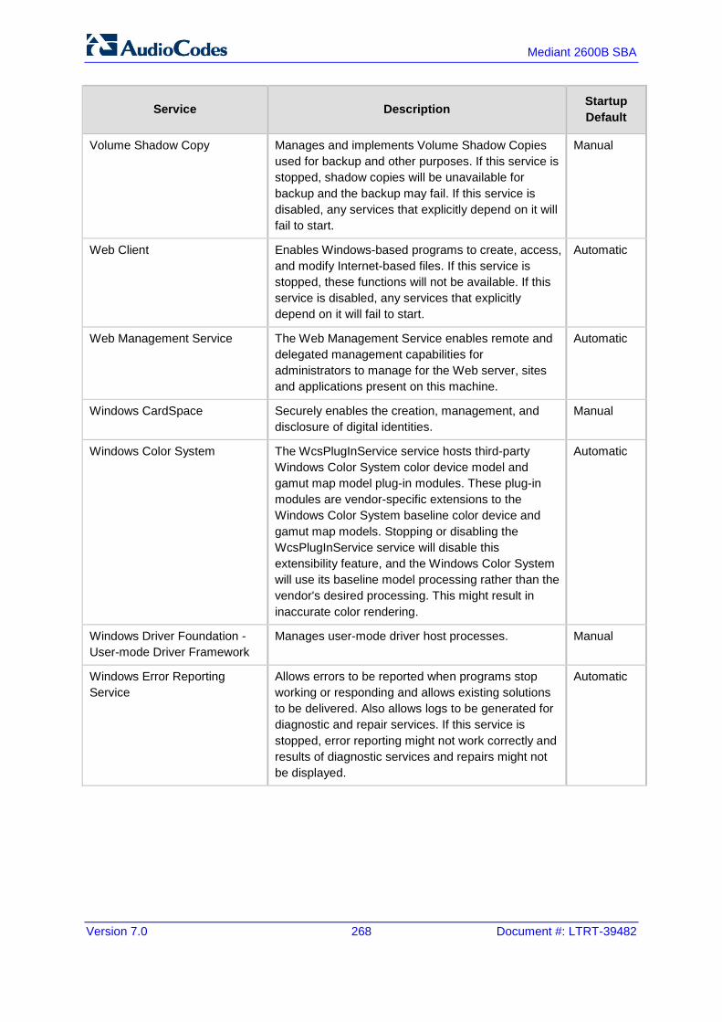
Version 7.0 268 Document #: LTRT-39482
Mediant 2600B SBA
Service Description Startup Default
Volume Shadow Copy Manages and implements Volume Shadow Copies used for backup and other purposes. If this service is stopped, shadow copies will be unavailable for backup and the backup may fail. If this service is disabled, any services that explicitly depend on it will fail to start.
Manual
Web Client Enables Windows-based programs to create, access, and modify Internet-based files. If this service is stopped, these functions will not be available. If this service is disabled, any services that explicitly depend on it will fail to start.
Automatic
Web Management Service The Web Management Service enables remote and delegated management capabilities for administrators to manage for the Web server, sites and applications present on this machine.
Automatic
Windows CardSpace Securely enables the creation, management, and disclosure of digital identities.
Manual
Windows Color System The WcsPlugInService service hosts third-party Windows Color System color device model and gamut map model plug-in modules. These plug-in modules are vendor-specific extensions to the Windows Color System baseline color device and gamut map models. Stopping or disabling the WcsPlugInService service will disable this extensibility feature, and the Windows Color System will use its baseline model processing rather than the vendor's desired processing. This might result in inaccurate color rendering.
Automatic
Windows Driver Foundation - User-mode Driver Framework
Manages user-mode driver host processes. Manual
Windows Error Reporting Service
Allows errors to be reported when programs stop working or responding and allows existing solutions to be delivered. Also allows logs to be generated for diagnostic and repair services. If this service is stopped, error reporting might not work correctly and results of diagnostic services and repairs might not be displayed.
Automatic
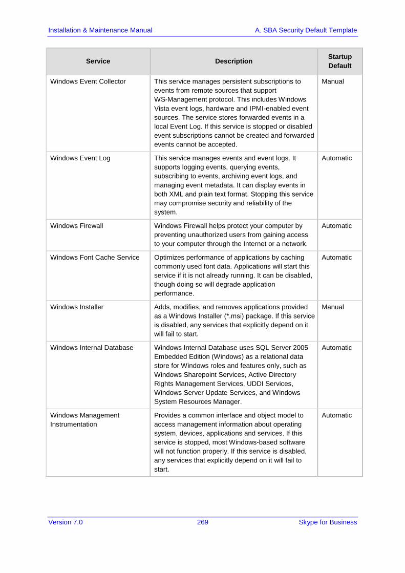
Version 7.0 269 Skype for Business
Installation & Maintenance Manual A. SBA Security Default Template
Service Description Startup Default
Windows Event Collector This service manages persistent subscriptions to events from remote sources that support WS-Management protocol. This includes Windows Vista event logs, hardware and IPMI-enabled event sources. The service stores forwarded events in a local Event Log. If this service is stopped or disabled event subscriptions cannot be created and forwarded events cannot be accepted.
Manual
Windows Event Log This service manages events and event logs. It supports logging events, querying events, subscribing to events, archiving event logs, and managing event metadata. It can display events in both XML and plain text format. Stopping this service may compromise security and reliability of the system.
Automatic
Windows Firewall Windows Firewall helps protect your computer by preventing unauthorized users from gaining access to your computer through the Internet or a network.
Automatic
Windows Font Cache Service Optimizes performance of applications by caching commonly used font data. Applications will start this service if it is not already running. It can be disabled, though doing so will degrade application performance.
Automatic
Windows Installer Adds, modifies, and removes applications provided as a Windows Installer (*.msi) package. If this service is disabled, any services that explicitly depend on it will fail to start.
Manual
Windows Internal Database Windows Internal Database uses SQL Server 2005 Embedded Edition (Windows) as a relational data store for Windows roles and features only, such as Windows Sharepoint Services, Active Directory Rights Management Services, UDDI Services, Windows Server Update Services, and Windows System Resources Manager.
Automatic
Windows Management Instrumentation
Provides a common interface and object model to access management information about operating system, devices, applications and services. If this service is stopped, most Windows-based software will not function properly. If this service is disabled, any services that explicitly depend on it will fail to start.
Automatic

Version 7.0 270 Document #: LTRT-39482
Mediant 2600B SBA
Service Description Startup Default
Windows Modules Installer Enables installation, modification, and removal of Windows updates and optional components. If this service is disabled, install or uninstall of Windows updates might fail for this computer.
Manual
Windows Presentation Foundation Font Cache 3.0.0.0
Optimizes performance of Windows Presentation Foundation (WPF) applications by caching commonly used font data. WPF applications will start this service if it is not already running. It can be disabled, though doing so will degrade the performance of WPF applications.
Manual
Windows Process Activation Service
The Windows Process Activation Service (WAS) provides process activation, resource management and health management services for message-activated applications.
Automatic
Windows Remote Management (WS-Management)
Windows Remote Management (WinRM) service implements the WS-Management protocol for remote management. WS-Management is a standard web services protocol used for remote software and hardware management. The WinRM service listens on the network for WS-Management requests and processes them. The WinRM Service needs to be configured with a listener using winrm.cmd command line tool or through Group Policy in order for it to listen over the network. The WinRM service provides access to WMI data and enables event collection. Event collection and subscription to events require that the service is running. WinRM messages use HTTP and HTTPS as transports. The WinRM service does not depend on IIS but is preconfigured to share a port with IIS on the same machine. The WinRM service reserves the /wsman URL prefix. To prevent conflicts with IIS, administrators should ensure that any websites hosted on IIS do not use the /wsman URL prefix.
Automatic
Windows Search Provides content indexing and property caching for file, email and other content (via extensibility APIs). The service responds to file and email notifications to index modified content. If the service is stopped or disabled, the Explorer will not be able to display virtual folder views of items, and search in the Explorer will fall back to item-by-item slow search.
Automatic
Windows SharePoint Services Timer
Sends notifications and performs scheduled tasks for Windows SharePoint Services
Automatic

Version 7.0 271 Skype for Business
Installation & Maintenance Manual A. SBA Security Default Template
Service Description Startup Default
Windows SharePoint Services Tracing
Manages trace output Automatic
Windows SharePoint Services VSS Writer
Windows SharePoint Services VSS Writer Manual
Windows System Resource Manager
Assigns computer resources to multiple applications running on Windows Vista Server. If this service is stopped or disabled, no management will occur, no accounting data will be collected, and the administrator will not be able to administer Windows System Resource Manager.
Automatic
Windows Time Maintains date and time synchronization on all clients and servers in the network. If this service is stopped, date and time synchronization will be unavailable. If this service is disabled, any services that explicitly depend on it will fail to start.
Automatic
Windows Update Enables the detection, download, and installation of updates for Windows and other programs. If this service is disabled, users of this computer will not be able to use Windows Update or its automatic updating feature, and programs will not be able to use the Windows Update Agent (WUA) API.
Disable
WinHTTP Web Proxy Auto-Discovery Service
WinHTTP implements the client HTTP stack and provides developers with a Win32 API and COM Automation component for sending HTTP requests and receiving responses. In addition, WinHTTP provides support for auto-discovering a proxy configuration via its implementation of the Web Proxy Auto-Discovery (WPAD) protocol.
Manual
WINS Manages the Windows Internet Name Service (WINS), which translates NetBIOS computer names to IP addresses.
Automatic
Wired AutoConfig The Wired AutoConfig (DOT3SVC) service is responsible for performing IEEE 802.1X authentication on Ethernet interfaces. If your current wired network deployment enforces 802.1X authentication, the DOT3SVC service should be configured to run for establishing Layer 2 connectivity and/or providing access to network resources. Wired networks that do not enforce 802.1X authentication are unaffected by the DOT3SVC service.
Manual

Version 7.0 272 Document #: LTRT-39482
Mediant 2600B SBA
Service Description Startup Default
WMI Performance Adapter Provides performance library information from Windows Management Instrumentation (WMI) providers to clients on the network. This service only runs when Performance Data Helper is activated.
Manual
Workstation Creates and maintains client network connections to remote servers using the SMB protocol. If this service is stopped, these connections will be unavailable. If this service is disabled, any services that explicitly depend on it will fail to start.
Automatic
World Wide Web Publishing Service
Provides Web connectivity and administration through the Internet Information Services Manager.
Automatic
A.5 Windows Update Policy Note the following in reference to Windows Update Policy:
AudioCodes is obligated to test and approve all SBA Cumulative Updates (CU) within 1 month of Microsoft releasing them.
AudioCodes ships all SBAs with the Windows Update service disabled as default (Never check for updates (not recommended).
AudioCodes does not test (as a rule) every Windows Update released by Microsoft.
In case customers wish to enable the Windows Update service- Install Updates automatically (recommended) (according to their corporate update policy), they can verify the updates, based upon Microsoft’s recommendations.
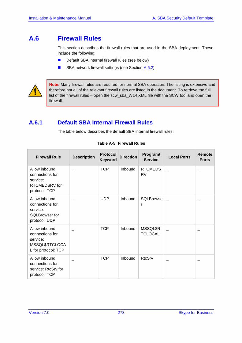
Version 7.0 273 Skype for Business
Installation & Maintenance Manual A. SBA Security Default Template
A.6 Firewall Rules This section describes the firewall rules that are used in the SBA deployment. These include the following:
Default SBA internal firewall rules (see below)
SBA network firewall settings (see Section A.6.2)
Note: Many firewall rules are required for normal SBA operation. The listing is extensive and therefore not all of the relevant firewall rules are listed in the document. To retrieve the full list of the firewall rules – open the scw_sba_W14 XML file with the SCW tool and open the firewall.
A.6.1 Default SBA Internal Firewall Rules The table below describes the default SBA internal firewall rules.
Table A-5: Firewall Rules
Firewall Rule Description Protocol Keyword Direction Program/
Service Local Ports Remote Ports
Allow inbound connections for service: RTCMEDSRV for protocol: TCP
_ TCP Inbound RTCMEDSRV
_ _
Allow inbound connections for service: SQLBrowser for protocol: UDP
_ UDP Inbound SQLBrowser
_ _
Allow inbound connections for service: MSSQL$RTCLOCAL for protocol: TCP
_ TCP Inbound MSSQL$RTCLOCAL
_ _
Allow inbound connections for service: RtcSrv for protocol: TCP
_ TCP Inbound RtcSrv _ _
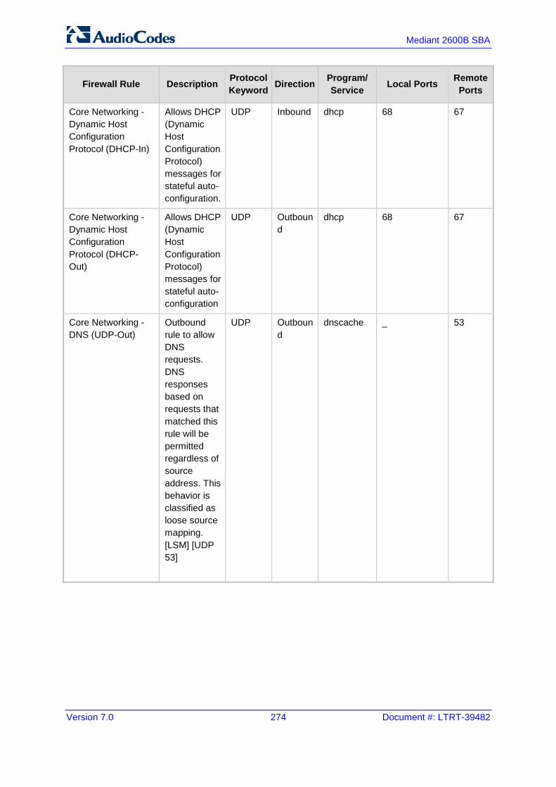
Version 7.0 274 Document #: LTRT-39482
Mediant 2600B SBA
Firewall Rule Description Protocol Keyword Direction Program/
Service Local Ports Remote Ports
Core Networking - Dynamic Host Configuration Protocol (DHCP-In)
Allows DHCP (Dynamic Host Configuration Protocol) messages for stateful auto-configuration.
UDP Inbound dhcp 68 67
Core Networking - Dynamic Host Configuration Protocol (DHCP-Out)
Allows DHCP (Dynamic Host Configuration Protocol) messages for stateful auto-configuration
UDP Outbound
dhcp 68 67
Core Networking - DNS (UDP-Out)
Outbound rule to allow DNS requests. DNS responses based on requests that matched this rule will be permitted regardless of source address. This behavior is classified as loose source mapping. [LSM] [UDP 53]
UDP Outbound
dnscache _ 53
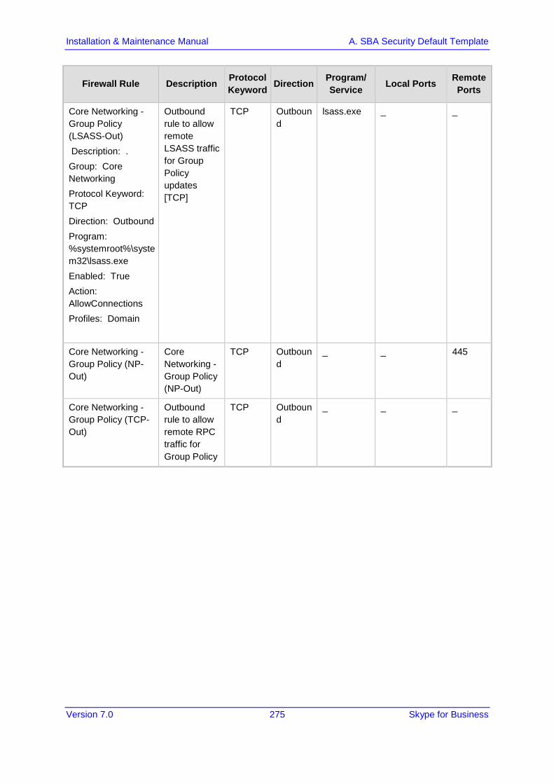
Version 7.0 275 Skype for Business
Installation & Maintenance Manual A. SBA Security Default Template
Firewall Rule Description Protocol Keyword Direction Program/
Service Local Ports Remote Ports
Core Networking - Group Policy (LSASS-Out) Description: . Group: Core Networking Protocol Keyword: TCP Direction: Outbound Program: %systemroot%\system32\lsass.exe Enabled: True Action: AllowConnections Profiles: Domain
Outbound rule to allow remote LSASS traffic for Group Policy updates [TCP]
TCP Outbound
lsass.exe _ _
Core Networking - Group Policy (NP-Out)
Core Networking - Group Policy (NP-Out)
TCP Outbound
_ _ 445
Core Networking - Group Policy (TCP-Out)
Outbound rule to allow remote RPC traffic for Group Policy
TCP Outbound
_ _ _

Version 7.0 276 Document #: LTRT-39482
Mediant 2600B SBA
Firewall Rule Description Protocol Keyword Direction Program/
Service Local Ports Remote Ports
Core Networking - Destination Unreachable Fragmentation Needed (ICMPv4-In)
Destination Unreachable Fragmentation Needed error messages are sent from any node that a packet traverses which is unable to forward the packet because fragmentation was needed and the don’t fragment bit was set.
ICMP_V4
Inbound _ _ _
Core Networking - Destination Unreachable (ICMPv6-In)
Destination Unreachable error messages are sent from any node that a packet traverses which is unable to forward the packet for any reason except congestion.
ICMP_V6
Inbound _ _ _

Version 7.0 277 Skype for Business
Installation & Maintenance Manual A. SBA Security Default Template
Firewall Rule Description Protocol Keyword Direction Program/
Service Local Ports Remote Ports
Core Networking - Multicast Listener Done (ICMPv6-In)
Multicast Listener Done messages inform local routers that there are no longer any members remaining for a specific multicast address on the subnet.
ICMP_V6
Inbound _ _ _
Core Networking - Multicast Listener Done (ICMPv6-Out)
Multicast Listener Done messages inform local routers that there are no longer any members remaining for a specific multicast address on the subnet
ICMP_V6
Outbound
_ _ _
Core Networking - Multicast Listener Query (ICMPv6-In)
An IPv6 multicast-capable router uses the Multicast Listener Query message to query a link for multicast group membership
ICMP_V6
Inbound _ _ _

Version 7.0 278 Document #: LTRT-39482
Mediant 2600B SBA
Firewall Rule Description Protocol Keyword Direction Program/
Service Local Ports Remote Ports
Core Networking - Multicast Listener Query (ICMPv6-Out)
An IPv6 multicast-capable router uses the Multicast Listener Query message to query a link for multicast group membership
ICMP_V6
Outbound
_ _ _
Core Networking - Multicast Listener Report (ICMPv6-Out)
The Multicast Listener Report message is used by a listening node to either immediately report its interest in receiving multicast traffic at a specific multicast address or in response to a Multicast Listener Query
ICMP_V6
Outbound
_ _ _

Version 7.0 279 Skype for Business
Installation & Maintenance Manual A. SBA Security Default Template
Firewall Rule Description Protocol Keyword Direction Program/
Service Local Ports Remote Ports
Core Networking - Multicast Listener Report v2 (ICMPv6-In)
Multicast Listener Report v2 message is used by a listening node to either immediately report its interest in receiving multicast traffic at a specific multicast address or in response to a Multicast Listener Query
ICMP_V6
Inbound _ _ _
Core Networking - Multicast Listener Report v2 (ICMPv6-Out)
Multicast Listener Report v2 message is used by a listening node to either immediately report its interest in receiving multicast traffic at a specific multicast address or in response to a Multicast Listener Query
ICMP_V6
Outbound
_ _ _
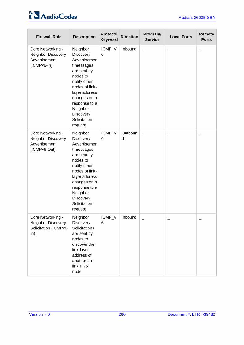
Version 7.0 280 Document #: LTRT-39482
Mediant 2600B SBA
Firewall Rule Description Protocol Keyword Direction Program/
Service Local Ports Remote Ports
Core Networking - Neighbor Discovery Advertisement (ICMPv6-In)
Neighbor Discovery Advertisement messages are sent by nodes to notify other nodes of link-layer address changes or in response to a Neighbor Discovery Solicitation request
ICMP_V6
Inbound _ _ _
Core Networking - Neighbor Discovery Advertisement (ICMPv6-Out)
Neighbor Discovery Advertisement messages are sent by nodes to notify other nodes of link-layer address changes or in response to a Neighbor Discovery Solicitation request
ICMP_V6
Outbound
_ _ _
Core Networking - Neighbor Discovery Solicitation (ICMPv6-In)
Neighbor Discovery Solicitations are sent by nodes to discover the link-layer address of another on-link IPv6 node
ICMP_V6
Inbound _ _ _

Version 7.0 281 Skype for Business
Installation & Maintenance Manual A. SBA Security Default Template
Firewall Rule Description Protocol Keyword Direction Program/
Service Local Ports Remote Ports
Core Networking - Neighbor Discovery Solicitation (ICMPv6-Out)
Neighbor Discovery Solicitations are sent by nodes to discover the link-layer address of another on-link IPv6 node
ICMP_V6
Outbound
_ _ _
Core Networking - Parameter Problem (ICMPv6-In)
Parameter Problem error messages are sent by nodes as a result of incorrectly generated packets.
ICMP_V6
Inbound _ _ _
Core Networking - Parameter Problem (ICMPv6-Out)
Parameter Problem error messages are sent by nodes as a result of incorrectly generated packets
ICMP_V6
Outbound
_ _ _
Core Networking - Packet Too Big (ICMPv6-In) Description: . Group: Core Networking Protocol Keyword: ICMP_V6 Direction: Inbound
Packet Too Big error messages are sent from any node that a packet traverses which is unable to forward the packet because the packet is too large for the next link
ICMP_V6
Inbound _ _ _

Version 7.0 282 Document #: LTRT-39482
Mediant 2600B SBA
Firewall Rule Description Protocol Keyword Direction Program/
Service Local Ports Remote Ports
Core Networking - Packet Too Big (ICMPv6-Out)
Packet Too Big error messages are sent from any node that a packet traverses which is unable to forward the packet because the packet is too large for the next link
ICMP_V6
Outbound
_ _ _
Core Networking - Router Advertisement (ICMPv6-In)
Router Advertisement messages are sent by routers to other nodes for stateless auto-configuration
ICMP_V6
Inbound _ _ _
Core Networking - Router Advertisement (ICMPv6-Out)
Router Advertisement messages are sent by routers to other nodes for stateless auto-configuration.
ICMP_V6
Outbound
_ _ _
Core Networking - Router Solicitation (ICMPv6-Out)
Router Solicitation messages are sent by nodes seeking routers to provide stateless auto-configuration
ICMP_V6
Outbound
_ _ _

Version 7.0 283 Skype for Business
Installation & Maintenance Manual A. SBA Security Default Template
Firewall Rule Description Protocol Keyword Direction Program/
Service Local Ports Remote Ports
Core Networking - Time Exceeded (ICMPv6-In)
Time Exceeded error messages are generated from any node that a packet traverses if the Hop Limit value is decremented to zero at any point on the path.
ICMP_V6
Inbound _ _ _
Core Networking - Time Exceeded (ICMPv6-Out)
Time Exceeded error messages are generated from any node that a packet traverses if the Hop Limit value is decremented to zero at any point on the path.
ICMP_V6
Outbound
_ _ _
Core Networking - Internet Group Management Protocol (IGMP-In)
IGMP messages are sent and received by nodes to create, join and depart multicast groups.
IGMP Inbound _ _ _

Version 7.0 284 Document #: LTRT-39482
Mediant 2600B SBA
Firewall Rule Description Protocol Keyword Direction Program/
Service Local Ports Remote Ports
Core Networking - Internet Group Management Protocol (IGMP-Out)
IGMP messages are sent and received by nodes to create, join and depart multicast groups
IGMP Outbound
_ _ _
Core Networking - IPHTTPS (TCP-In)
Inbound TCP rule to allow IPHTTPS tunneling technology to provide connectivity across HTTP proxies and firewalls.
TCP Inbound _ _ _
Core Networking - IPHTTPS (TCP-Out)
Outbound TCP rule to allow IPHTTPS tunneling technology to provide connectivity across HTTP proxies and firewalls
TCP Outbound
_ _ _
Core Networking - IPv6 (IPv6-In)
Inbound rule required to permit IPv6 traffic for ISATAP (Intra-Site Automatic Tunnel Addressing Protocol) and 6to4 tunneling services.
IPV6 Inbound _ _ _

Version 7.0 285 Skype for Business
Installation & Maintenance Manual A. SBA Security Default Template
Firewall Rule Description Protocol Keyword Direction Program/
Service Local Ports Remote Ports
Core Networking - IPv6 (IPv6-Out)
Outbound rule required to permit IPv6 traffic for ISATAP (Intra-Site Automatic Tunnel Addressing Protocol) and 6to4 tunneling services
IPV6 Outbound
_ _ _
Core Networking - Teredo (UDP-In)
Inbound UDP rule to allow Teredo edge traversal, a technology that provides address assignment and automatic tunneling for unicast IPv6 traffic when an IPv6/IPv4 host is located behind an IPv4 network address translator.
UDP Inbound _ _ _

Version 7.0 286 Document #: LTRT-39482
Mediant 2600B SBA
Firewall Rule Description Protocol Keyword Direction Program/
Service Local Ports Remote Ports
Core Networking - Teredo (UDP-Out)
Outbound UDP rule to allow Teredo edge traversal, a technology that provides address assignment and automatic tunneling for unicast IPv6 traffic when an IPv6/IPv4 host is located behind an IPv4 network address translator
UDP Outbound
_ _ _
File and Printer Sharing (Echo Request - ICMPv4-In)
Echo Request messages are sent as ping requests to other nodes
ICMP_V4
Inbound _ _ _
File and Printer Sharing (Echo Request - ICMPv4-Out)
Echo Request messages are sent as ping requests to other nodes. Group: File and Printer Sharing
ICMP_V4
Outbound
_ _ _

Version 7.0 287 Skype for Business
Installation & Maintenance Manual A. SBA Security Default Template
Firewall Rule Description Protocol Keyword Direction Program/
Service Local Ports Remote Ports
File and Printer Sharing (Echo Request - ICMPv6-In)
Echo Request messages are sent as ping requests to other nodes
ICMP_V6
Inbound _ _ _
File and Printer Sharing (Echo Request - ICMPv6-Out)
Echo Request messages are sent as ping requests to other nodes
ICMP_V6
Outbound
_ _ _
File and Printer Sharing (NB-Datagram-In)
Inbound rule for File and Printer Sharing to allow NetBIOS Datagram transmission and reception. [UDP 138]
UDP Inbound _ 138 _
File and Printer Sharing (NB-Datagram-Out)
Outbound rule for File and Printer Sharing to allow NetBIOS Datagram transmission and reception. [UDP 138]
UDP Outbound
_ _ 138
File and Printer Sharing (NB-Name-In)
Inbound rule for File and Printer Sharing to allow NetBIOS Name Resolution. [UDP 137]
UDP Inbound _ 137 _
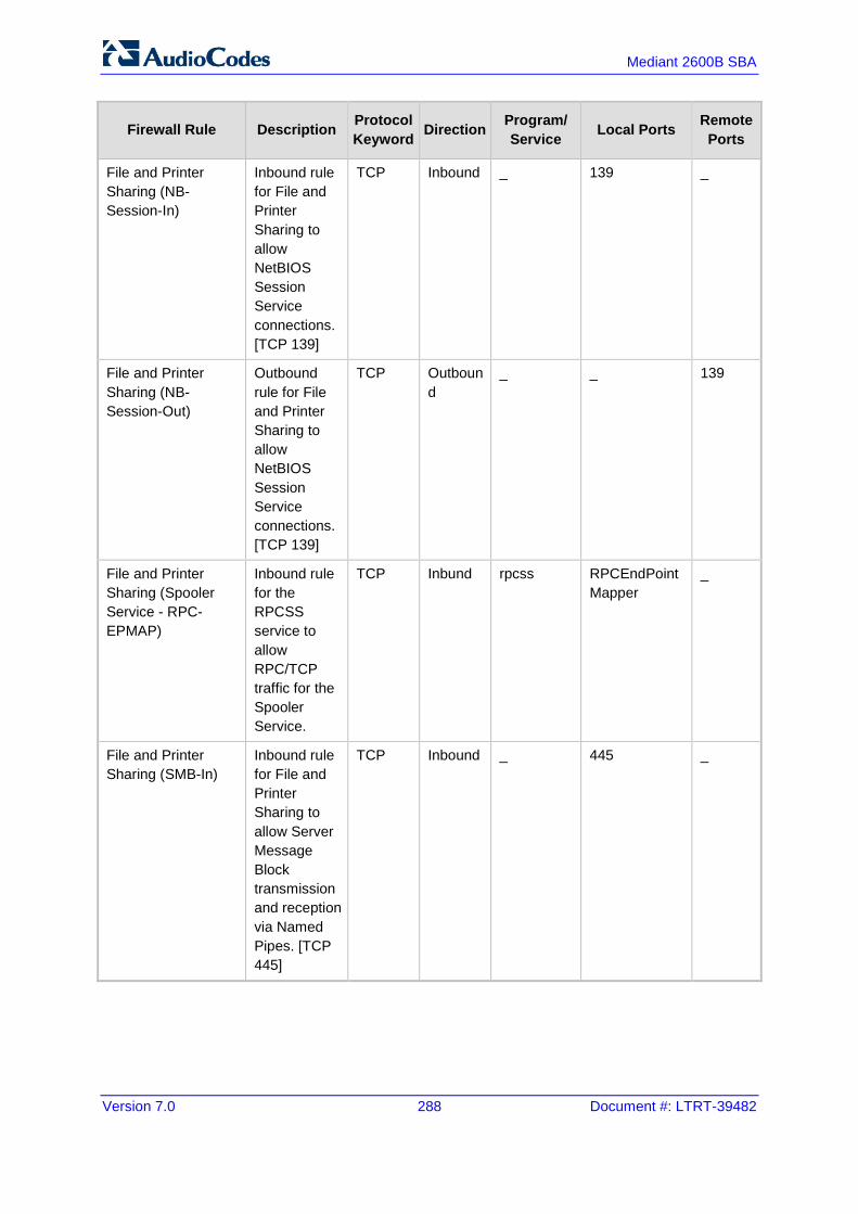
Version 7.0 288 Document #: LTRT-39482
Mediant 2600B SBA
Firewall Rule Description Protocol Keyword Direction Program/
Service Local Ports Remote Ports
File and Printer Sharing (NB-Session-In)
Inbound rule for File and Printer Sharing to allow NetBIOS Session Service connections. [TCP 139]
TCP Inbound _ 139 _
File and Printer Sharing (NB-Session-Out)
Outbound rule for File and Printer Sharing to allow NetBIOS Session Service connections. [TCP 139]
TCP Outbound
_ _ 139
File and Printer Sharing (Spooler Service - RPC-EPMAP)
Inbound rule for the RPCSS service to allow RPC/TCP traffic for the Spooler Service.
TCP Inbund rpcss RPCEndPointMapper
_
File and Printer Sharing (SMB-In)
Inbound rule for File and Printer Sharing to allow Server Message Block transmission and reception via Named Pipes. [TCP 445]
TCP Inbound _ 445 _
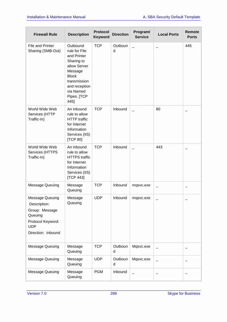
Version 7.0 289 Skype for Business
Installation & Maintenance Manual A. SBA Security Default Template
Firewall Rule Description Protocol Keyword Direction Program/
Service Local Ports Remote Ports
File and Printer Sharing (SMB-Out)
Outbound rule for File and Printer Sharing to allow Server Message Block transmission and reception via Named Pipes. [TCP 445]
TCP Outbound
_ _ 445
World Wide Web Services (HTTP Traffic-In)
An inbound rule to allow HTTP traffic for Internet Information Services (IIS) [TCP 80]
TCP Inbound _ 80 _
World Wide Web Services (HTTPS Traffic-In)
An inbound rule to allow HTTPS traffic for Internet Information Services (IIS) [TCP 443]
TCP Inbound _ 443 _
Message Queuing Message Queuing
TCP Inbound mqsvc.exe _ _
Message Queuing Description: Group: Message Queuing Protocol Keyword: UDP Direction: Inbound
Message Queuing
UDP Inbound mqsvc.exe _ _
Message Queuing Message Queuing
TCP Outbound
Mqsvc.exe _ _
Message Queuing Message Queuing
UDP Outbound
Mqsvc.exe _ _
Message Queuing Message Queuing
PGM Inbound _ _ _
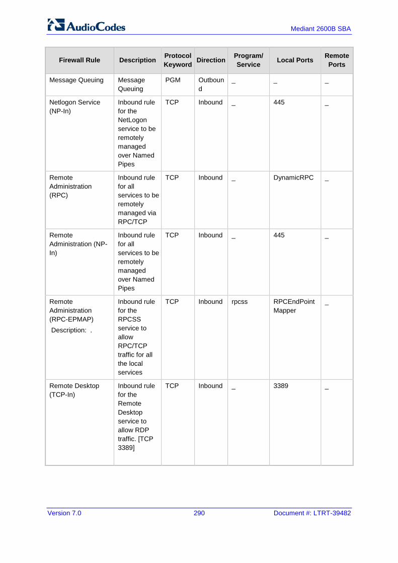
Version 7.0 290 Document #: LTRT-39482
Mediant 2600B SBA
Firewall Rule Description Protocol Keyword Direction Program/
Service Local Ports Remote Ports
Message Queuing Message Queuing
PGM Outbound
_ _ _
Netlogon Service (NP-In)
Inbound rule for the NetLogon service to be remotely managed over Named Pipes
TCP Inbound _ 445 _
Remote Administration (RPC)
Inbound rule for all services to be remotely managed via RPC/TCP
TCP Inbound _ DynamicRPC _
Remote Administration (NP-In)
Inbound rule for all services to be remotely managed over Named Pipes
TCP Inbound _ 445 _
Remote Administration (RPC-EPMAP) Description: .
Inbound rule for the RPCSS service to allow RPC/TCP traffic for all the local services
TCP Inbound rpcss RPCEndPointMapper
_
Remote Desktop (TCP-In)
Inbound rule for the Remote Desktop service to allow RDP traffic. [TCP 3389]
TCP Inbound _ 3389 _

Version 7.0 291 Skype for Business
Installation & Maintenance Manual A. SBA Security Default Template
Firewall Rule Description Protocol Keyword Direction Program/
Service Local Ports Remote Ports
Remote Event Log Management (RPC)
Inbound rule for the local Event Log service to be remotely managed via RPC/TCP.
TCP Inbound _ DynamicRPC _
Remote Event Log Management (NP-In)
Inbound rule for the local Event Log service to be remotely managed over Named Pipes
TCP Inbound _ 445 _
Remote Event Log Management (RPC-EPMAP)
Inbound rule for the RPCSS service to allow RPC/TCP traffic for the local Event Log Service.
TCP Inbound Rpcss RPCEndPointMapper
_
Windows Firewall Remote Management (RPC)
Inbound rule for the Windows Firewall to be remotely managed via RPC/TCP
TCP Inbound policyagent DynamicRPC _
Windows Firewall Remote Management (RPC-EPMAP)
Inbound rule for the RPCSS service to allow RPC/TCP traffic for the Windows Firewall
TCP Inbound rpcss RPCEndPointMapper
_

Version 7.0 292 Document #: LTRT-39482
Mediant 2600B SBA
Firewall Rule Description Protocol Keyword Direction Program/
Service Local Ports Remote Ports
SCW remote access firewall rule - Scshost - Dynamic RPC
Allow inbound access for scshost using dynamic RPC and protocol TCP
TCP Inbound scshost DynamicRPC _
SCW remote access firewall rule - Scshost - End Point RPC Mapper
Allow inbound access for scshost using end point RPC mapper and protocol TCP
TCP Inbound scshost RPCEndPointMapper
_
SCW remote access firewall rule - Svchost - TCP
Allow inbound access for svchost using port 135 and protocol TCP
TCP Inbound svschost 135 _
SCW inbound access firewall rule - System - TCP
Allow inbound access for system using ports 139, 445 and protocol TCP
TCP Inbound _ 139, 445 _
SCW remote access firewall rule - System - UDP
Allow inbound access for system using port 137 and protocol UDP
UDP Inbound _ 137 _
SNMP Service (UDP In)
Inbound rule for the Simple Network Management Protocol (SNMP) Service to allow SNMP traffic. [UDP 161]
UDP Inbound snmp 161 _

Version 7.0 293 Skype for Business
Installation & Maintenance Manual A. SBA Security Default Template
Firewall Rule Description Protocol Keyword Direction Program/
Service Local Ports Remote Ports
SNMP Trap Service (UDP In)
Inbound rule for the SNMP Trap Service to allow SNMP traps. [UDP 162]
UDP Inbound snmptrap 162 LocalSubnet
SNMP Trap Service (UDP In)
Inbound rule for the SNMP Trap Service to allow SNMP traps. [UDP 162]
UDP Inbound snmptrap 162 _
Windows Communication Foundation Net.TCP Listener Adapter (TCP-In)
An inbound rule for Windows Communication Foundation to allow TCP traffic to the Net.TCP Listener Adapter [TCP 808]
TCP Inbound nettcpactivator
808 _
Windows Management Instrumentation (ASync-In)
Inbound rule to allow Asynchronous WMI traffic for remote Windows Management Instrumentation. [TCP]
TCP Inbound Unsecapp _ _

Version 7.0 294 Document #: LTRT-39482
Mediant 2600B SBA
A.6.2 SBA Network Firewall Settings The table below describes the various network firewall settings that are required for connections between the different components in the SBA network.
Table A-6: SBA Network Firewall Setting
Source Destination Destination port Transport Protocol Notes
CMS SBA 445 TCP SMB Central Management Server Replication
Front End Servers SBA 5061 TCP SIP/MTLS SIP Signalling
Front End Servers SBA 444 TCP HTTPS Certificate replication
Front End Servers SBA 50001 TCP SIP/MTLS Centralized Logging
Service
Front End Servers SBA 50002 TCP SIP/MTLS Centralized Logging
Service
Front End Servers SBA 50003 TCP SIP/MTLS Centralized Logging
Service
Front End Servers SBA 5090 TCP SIP/MTLS WinFabFederationPort
Front End Servers SBA 5091 TCP SIP/MTLS WinFabLeaseAgentPort
Front End Servers SBA 5092 TCP SIP/MTLS WinFabClientConnectionP
ort
Front End Servers SBA 5093 TCP SIP/MTLS WinFabIPCPort
Front End Servers SBA 5094 TCP SIP/MTLS WinFabReplicationPort
SBA Front End Servers 444 TCP HTTPS Certificate replication
SBA Front End Servers 5061 TCP SIP/MTLS SIP signalling
SBA Front End Servers 5088 TCP SIP/MTLS Lync 2013 mobility -
UCWA
SBA Front End Servers 5089 TCP SIP/MTLS Lync 2013 mobility-UCWA
SBA Front End Servers 50001 TCP SIP/MTLS Centralized Logging
Service

Version 7.0 295 Skype for Business
Installation & Maintenance Manual A. SBA Security Default Template
Source Destination Destination port Transport Protocol Notes
SBA Front End Servers 50002 TCP SIP/MTLS Centralized Logging
Service
SBA Front End Servers 50003 TCP SIP/MTLS Centralized Logging
Service
SBA Front End Servers 5090 TCP SIP/MTLS WinFabFederationPort
SBA Front End Servers 5091 TCP SIP/MTLS WinFabLeaseAgentPort
SBA Front End Servers 5092 TCP SIP/MTLS WinFabClientConnectionP
ort
SBA Front End Servers 5093 TCP SIP/MTLS WinFabIPCPort
SBA Front End Servers 5094 TCP SIP/MTLS WinFabReplicationPort
SBA Director 444 TCP HTTPS Certificate replication
SBA Edge Pool 5062 TCP SIP/MTLS SIP connection for requesting MRAS credentials
SBA Edge Pool 443 TCP SRTP Audio Ports to external
SBA Edge Pool 3478 UDP SRTP Audio Ports to external

Version 7.0 296 Document #: LTRT-39482
Mediant 2600B SBA
This page is intentionally left blank.

Version 7.0 297 Skype for Business
Installation & Maintenance Manual B. Running Anti-Virus Software
B Running Anti-Virus Software When Anti-Virus software is run on SBA components, ensure that the Antivirus file scanning exclusions are based on the following Microsoft recommendations:
SBA with Microsoft Lync 2010: https://technet.microsoft.com/en-us/library/gg195736.aspx
SBA with Microsoft Lync 2013: https://technet.microsoft.com/en-us/library/dn440138%28v=ocs.15%29.aspx

Version 7.0 298 Document #: LTRT-39482
Mediant 2600B SBA
This page is intentionally left blank.

Version 7.0 299 Skype for Business
Installation & Maintenance Manual C. Configuring RAID
C Configuring RAID This appendix describes how to set up and enable RAID 1 (Redundant Array of Independent Disks) on the Mediant 2600B SBA. RAID 1 is achieved by using two installed OSN hard drives (HDMX) that serve as Master-Slave configuration, where the Slave disk has an exact copy (or mirror) of the data on the Master disk. Thus, RAID 1 provides redundancy of the SBA in case of failure of one of the disks.
C.1 Prerequisites Before configuring RAID, ensure that you do the following:
Complete the SBA installation and configuration as described in Chapter '8' on page 79 .
Ensure that the HDMX disk in Slot 8 (slave) is unallocated (without a volume allocated).
Ensure that the storage capacity of both the HDMX disks is identical (e.g., 120 GB).
C.2 Slot Assignments for OSN Hard Drives The Mediant 2600B SBA rear panel is displayed in the figure below and described in the subsequent table.
Table C-1: OSN Slot Assignment
Slot # Description
5 OSN4 Module
6 HDMX Master – Hard Disk functionality for OSN platform.
7 HDMX Slave – Hard Disk functionality for OSN platform.
Note: Power down the device before inserting the HDMX into Slot 7.
Before inserting the second hard disk drive, ensure that this drive is compatible with the existing SBA hard disk drive storage as described in the table below.

Version 7.0 300 Document #: LTRT-39482
Mediant 2600B SBA
Table C-2: Mediant 2600B SBA HDD Type RAID 1 Compatibility Table
SBA Prime Storage Type Second HDD for RAID
M1KB SBA2G or 4G HDMX M1KB-HDD
M1KB-4G-SBA-SSD SSD M1KB-SSD-120
M1KB-SBA-SSD SSD M1KB-SSD-120
M1KB-SBA-ES SSD M1KB-SSD-120 All SBA family products with a CPN which ends with ES
C.3 Configuring RAID 1 The procedure below describes how to configure RAID 1 on the Mediant 2600B SBA. The procedure below describes how to configure RAID 1 on the Mediant 2600B SBA.
Note: As this is an uptime solution (i.e., it allows you to plan the installation and keep the SBA running using the secondary HDD), if there is a hard disk failure, a complete re-install of the SBA is required.
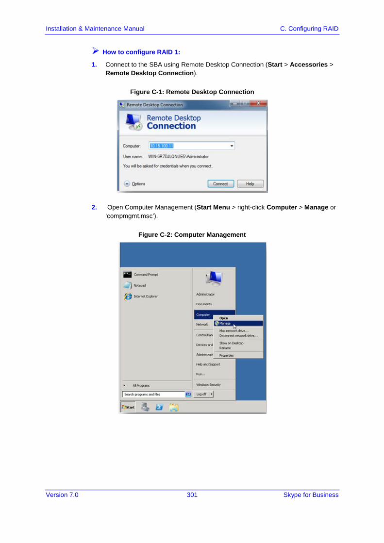
Version 7.0 301 Skype for Business
Installation & Maintenance Manual C. Configuring RAID
How to configure RAID 1:
1. Connect to the SBA using Remote Desktop Connection (Start > Accessories > Remote Desktop Connection).
Figure C-1: Remote Desktop Connection
2. Open Computer Management (Start Menu > right-click Computer > Manage or ‘compmgmt.msc’).
Figure C-2: Computer Management

Version 7.0 302 Document #: LTRT-39482
Mediant 2600B SBA
3. In the Server Manager, navigate to the Disk Management menu option.
Figure C-3: Disk Management
4. Convert the disks to ‘Dynamic’ by right-clicking Disc 0, and then selecting the Convert to Dynamic Disk menu option.
Figure C-4: Convert to Dynamic Disk
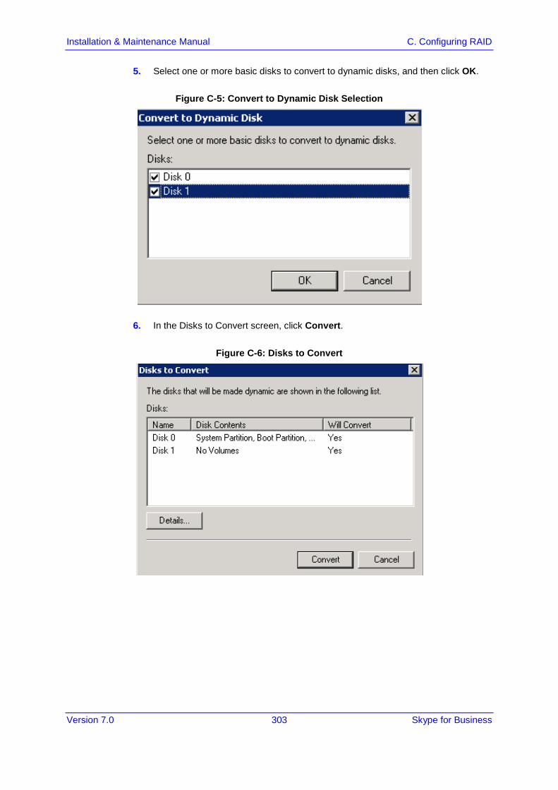
Version 7.0 303 Skype for Business
Installation & Maintenance Manual C. Configuring RAID
5. Select one or more basic disks to convert to dynamic disks, and then click OK.
Figure C-5: Convert to Dynamic Disk Selection
6. In the Disks to Convert screen, click Convert.
Figure C-6: Disks to Convert

Version 7.0 304 Document #: LTRT-39482
Mediant 2600B SBA
7. In the Disk Management screen, click Yes.
Figure C-7: Disks Management
8. Add the Mirror, by right-clicking Partition C, and then select the Add Mirror menu option.
Figure C-8: Add Mirror
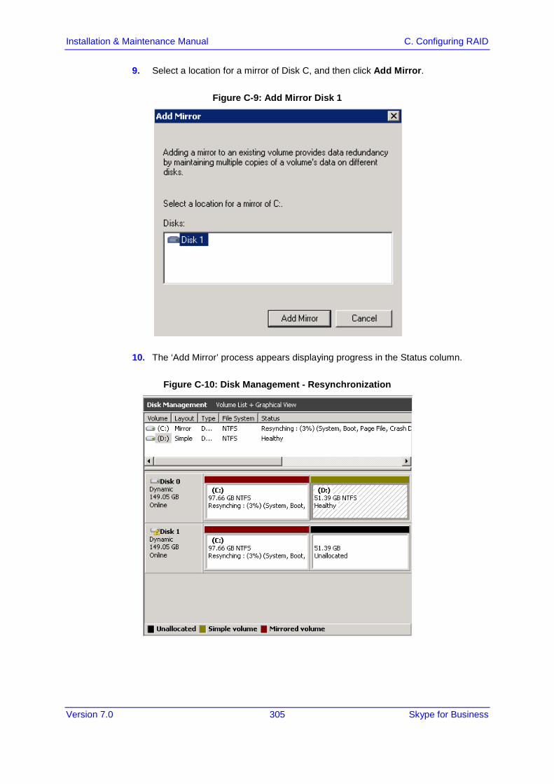
Version 7.0 305 Skype for Business
Installation & Maintenance Manual C. Configuring RAID
9. Select a location for a mirror of Disk C, and then click Add Mirror.
Figure C-9: Add Mirror Disk 1
10. The ‘Add Mirror’ process appears displaying progress in the Status column.
Figure C-10: Disk Management - Resynchronization
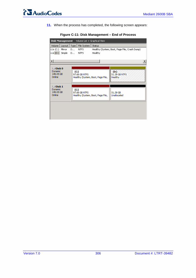
Version 7.0 306 Document #: LTRT-39482
Mediant 2600B SBA
11. When the process has completed, the following screen appears:
Figure C-11: Disk Management – End of Process

Version 7.0 307 Skype for Business
Installation & Maintenance Manual C. Configuring RAID
This page is intentionally left blank.

International Headquarters AudioCodes Inc. 1 Hayarden Street, 27 World’s Fair Drive, Airport City Somerset, NJ 08873 Lod 7019900, Israel Tel: +1-732-469-0880 Tel: +972-3-976-4000 Fax: +1-732-469-2298 Fax: +972-3-976-4040 Contact us: www.audiocodes.com/info Website: www.audiocodes.com
Document #: LTRT-39482