Mechatronics IIIM LM7: Fuzzy Control Introductiondata.mecheng.adelaide.edu.au/robotics/ IIIM LM7:...
21
Mechatronics IIIM LM7: Fuzzy Control 1 Objectives - To design and implement a fuzzy controller for a DC motor speed control system Introduction Laboratory sessions LM1 – LM7 have introduced the basic elements of a digital control system (ADC, timing engine, DAC). In this session we shall put all of these elements to use in designing and implementing a fuzzy logic based speed control system. One of the special features of the MC9S12DP256B/C microcontroller (formerly Motorola – now: freescale semiconductor, www.freescale.com ) is its built-in fuzzy logic support. Having been developed with fuzzy control applications in mind this microcontroller provides 4 special assembler instructions for the fuzzification of inputs, the fast and efficient evaluation of membership rules as well as for the concluding de- fuzzification. It is therefore possible to design extremely fast fuzzy controllers which minimal codes size requirements. Motorola claim that their controllers evaluate fuzzy inference systems approximately 50 times faster than comparable kernels implemented on typical midrange microcontrollers. The design of a fuzzy logic speed control system for a DC motor is best done using one of the many fuzzy logic software tools available today, e.g. the MATLAB Fuzzy Logic Toolbox or fuzzyTECH (INFORM GmbH). In this exercise we are going to use the evaluation version of fuzzyTECH, available free of charge at www.fuzzytech.com . This software tool has been installed for you in the Mechatronics laboratory as well as the CATS suite. The evaluation version is feature limited: The code generation function has not been included, the rule base is limited to a maximum of 50 rules and you cannot save your work. Start fuzzyTECH and define a system with two inputs (acceleration, speed_error) and one output (change_of_power). To assist you with this, fuzzyTECH offers you the help of the Design Wizard. Select File ջ Fuzzy Design Wizard… or click on the corresponding toolbar button (cf. Figure LM7-1). The Design Wizard takes you through all steps which are required to setup a working fuzzy controller. Choose to Create a New System and click on Next. Set the number of linguistic input variables (input LV) to 2 with 5 input terms per linguistic variable. Similarly, choose a single output LV with 5 terms. We won’t be using any Intermediate LVs (0). Click on Next and define the name of the first linguistic variable as speed_error. Specify a range from -1 to 1 and select the term names ‘very_negative, negative, zero, positive, very_positive’ . Click on Next and repeat this procedure for the second input (acceleration, range: -10 to 10, 3 terms, term names: ‘negative, zero, positive’) as well as the output variable (change_of_power, range: -1 to 1, 5 terms, term names: ‘very_negative, negative, zero, positive, very_positive’).
Transcript of Mechatronics IIIM LM7: Fuzzy Control Introductiondata.mecheng.adelaide.edu.au/robotics/ IIIM LM7:...

Mechatronics IIIM LM7: Fuzzy Control
1
Objectives - To design and implement a fuzzy controller for a DC motor speed control system Introduction Laboratory sessions LM1 – LM7 have introduced the basic elements of a digital control system (ADC, timing engine, DAC). In this session we shall put all of these elements to use in designing and implementing a fuzzy logic based speed control system. One of the special features of the MC9S12DP256B/C microcontroller (formerly Motorola – now: freescale semiconductor, www.freescale.com) is its built-in fuzzy logic support. Having been developed with fuzzy control applications in mind this microcontroller provides 4 special assembler instructions for the fuzzification of inputs, the fast and efficient evaluation of membership rules as well as for the concluding de-fuzzification. It is therefore possible to design extremely fast fuzzy controllers which minimal codes size requirements. Motorola claim that their controllers evaluate fuzzy inference systems approximately 50 times faster than comparable kernels implemented on typical midrange microcontrollers. The design of a fuzzy logic speed control system for a DC motor is best done using one of the many fuzzy logic software tools available today, e.g. the MATLAB Fuzzy Logic Toolbox or fuzzyTECH (INFORM GmbH). In this exercise we are going to use the evaluation version of fuzzyTECH, available free of charge at www.fuzzytech.com. This software tool has been installed for you in the Mechatronics laboratory as well as the CATS suite. The evaluation version is feature limited: The code generation function has not been included, the rule base is limited to a maximum of 50 rules and you cannot save your work. Start fuzzyTECH and define a system with two inputs (acceleration, speed_error) and one output (change_of_power). To assist you with this, fuzzyTECH offers you the help of the Design Wizard. Select File ջ Fuzzy Design Wizard… or click on the corresponding toolbar button (cf. Figure LM7-1). The Design Wizard takes you through all steps which are required to setup a working fuzzy controller. Choose to Create a New System and click on Next. Set the number of linguistic input variables (input LV) to 2 with 5 input terms per linguistic variable. Similarly, choose a single output LV with 5 terms. We won’t be using any Intermediate LVs (0). Click on Next and define the name of the first linguistic variable as speed_error. Specify a range from -1 to 1 and select the term names ‘very_negative, negative, zero, positive, very_positive’. Click on Next and repeat this procedure for the second input (acceleration, range: -10 to 10, 3 terms, term names: ‘negative, zero, positive’) as well as the output variable (change_of_power, range: -1 to 1, 5 terms, term names: ‘very_negative, negative, zero, positive, very_positive’).

Mechatronics IIIM LM7: Fuzzy Control
2
Figure LM7-1 FuzzyTech – launching the Design Wizard Upon definition of the linguistic variables, the Design Wizard lets you choose the method for defuzzification from two alternatives: Centre-of-Maximum (CoM) and Mean-of-Maximum (MoM) – cf. Figure LM7-2.
Figure LM7-2 FuzzyTech – defining the method for defuzzification

Mechatronics IIIM LM7: Fuzzy Control
3
The former method (CoM) is commonly used in control applications. CoM allows the output to assume any value within the specified output range. The second method (MoM) is mostly used in conjunction with feature recognition applications in which the output can only assume a fixed number of distinct values. As we are working with a continuous output variable (change_of_power) we choose the fuzzification method CoM. Click on Next to define the Rule Blocks. We are going to use a single Rule Block with a user-defined Degree-of-Strength (DoS) value of 0. Generate the project. You should be presented with a screen similar to Figure LM7-3.
Figure LM7-3 FuzzyTech – the generated system In its present form, the system does not include any form of expert knowledge about how the controller inputs influence the controller output. The rule base simply lists all combinations of all linguistic terms of both input variables leading to any of the linguistic terms of the output variable. This is a pretty big (and useless) table. Figure LM7-4 shows a small part of this generic rule base. You can inspect these rules by double-clicking onto the rule block RB1.
Mechatronics IIIM LM7: Fuzzy Control
4
Figure LM7-4 FuzzyTech – generic rule base (extract) To reduce this rule base to the essential rules which describe what an expert would be able to tell about the way the inputs influence the system output we can use the Rule Block Wizard (small circle in Figure LM7-4 … the icon is a rabbit of some sort in what presumably is the wizard’s hat – as for the slightly dubious stick… no idea!?). Clicking on the rabbit should bring up a small requester which allows us to define the influence input variable speed_error has on the output variable change_of_power (Figure LM7-5). As experts of DC motor control we know that a positive speed_error, i. e. the motor is running too fast, should lead to the reduction of output power, i. e. a negative change_of_power. The severity of this reaction can be controlled by adjusting the slider somewhere in between the linguistic extremes ‘not at all’ and ‘very negative’. Bear in mind that the linguistic term ‘very negative’ refers to the values near the negative end of the output range (here: -1 to 1). It is through choosing this range and specifying the relationship between linguistic inputs and linguistic outputs that we can tune the controller. Define the influence of the speed_error on the change_of_power as somewhere between negative and very negative. The more negative you make this correlation, the heavier a negative speed_error will be penalised.

Mechatronics IIIM LM7: Fuzzy Control
5
Figure LM7-5 fuzzyTECH – shaping the rule base Click on Next to progress to the next stage in which you are asked to specify the influence of the acceleration on the change_of_power. What type of correlation do you need to specify for a stable controller? (positive / negative) Once a suitable weight has been given to the acceleration term, click on End. FuzzyTECH issues a warning to make us aware of the fact that we are about to overwrite the existing rule base by a new set of rules (Figure LM7-6). Click on OK to authorize this replacement.
Figure LM7-6 fuzzyTECH – replacing an existing rule base The new rule base should be much shorter than the original one and the Degree-of-Strength (DoS) should have been adjusted to 1.0 (Figure LM7-7). With the latter you can apply a form of weighting to individual rules and/or switch them on (1.0) or off (0.0). In this exercise, we won’t use this additional feature and will therefore keep all DoS coefficients at 1.0.

Mechatronics IIIM LM7: Fuzzy Control
6
Figure LM7-7 fuzzyTECH – compacting the rule base Double click on the icon of the speed_error variable. You should be presented with a small window similar to the one shown in Figure LM7-8. This window allows you to manifest your expert knowledge about how you define the linguistic variables of your system.
Figure LM7-8 fuzzyTECH – defining the linguistic variables Adjust the terms to give the controller a better resolution near the centre (zero error). This can be done by moving the singleton values of the linguistic terms negative and positive inwards (cf. Figure LM7-8). If you like, you can also adjust the acceleration variable and/or the change_of_power output variable. The latter should maybe resemble the distribution used for the speed_error in that the outermost linguistic terms (very_negative and very_positive) are not triangularly shaped but remain at 1.0 towards the extremes of the accessible range (-1 and 1). Be advised that finding a

Mechatronics IIIM LM7: Fuzzy Control
7
working distribution of linguistic variables is a matter of experience and there is no right or wrong. Run the fuzzy controller by clicking on the Interactive button (a ‘bug’ this time… see Figure LM7-9). It is probably helpful if you re-arrange the windows a bit to see all input and output variables as well as the rule block window.
Figure LM7-9 fuzzyTECH – Running the controller in simulation mode Set the speed_error to -0.5 with an acceleration of -2.5. In the example shown in Figure LM7-9 this leads to a small positive change_of_output (0.16). Notice that this value is the weighted Centre of Maximum (CoM) of linguistic output terms zero and positive. The rule block window indicates that a total of 4 rules are involved in producing this result:
[1] IF acceleration IS negative AND speed_error IS very_negative THEN change_of_power IS positive
[2] IF acceleration IS negative AND speed_error IS negative THEN change_of_power IS positive
[3] IF acceleration IS zero AND speed_error IS very_negative THEN change_of_power IS zero
[4] IF acceleration IS zero AND speed_error IS negative THEN change_of_power IS zero
The degree of membership of input variable acceleration in the linguistic terms negative and zero is found to be 48% and 51%, respectively. This means that the current acceleration can be described as negative just as well as it can be referred to as zero. The speed_error, on the other hand, is 91% very_negative and 38% negative. We would therefore describe it as ‘more very_negative than negative’.

Mechatronics IIIM LM7: Fuzzy Control
8
When evaluating the above fuzzy rules, the fuzzy inference engine uses the two operators fuzzy OR and fuzzy AND. The mathematical definitions of these fuzzy operators are the maximum operator (fuzzy OR) and the minimum operator (fuzzy AND). With this in mind the above rules translate into the following operations:
[1] min(0.48, 0.91) = 0.48, change_of_power IS positive [2] min(0.48, 0.38) = 0.38, change_of_power IS positive [3] min(0.51, 0.91) = 0.51, change_of_power IS zero [4] min(0.51, 0.38) = 0.38, change_of_power IS zero
Rules that lead to the same linguistic term of the output (here: positive or zero) are now combined using a fuzzy OR (maximum operator). This leads to the following two output values:
[1], [2] max(0.48, 0.38) = 0.48, change_of_power IS positive [3], [4] max(0.51, 0.38) = 0.51, change_of_power IS zero
To combine these two values, the Centre of Maximum (CoM) method has been chosen. The centre of the linguistic output term zero is at zero, whereas term positive has its centre at 0.33. The weighted average is thus calculated to
16.099.0
1584.0
48.051.0
33.048.0051.0__ ==
+
⋅+⋅=powerofchange
Note that the Degree of Strength of individual rules (DoS = 1.0) can be used to reduce their impact on the output variable. FuzzyTECH symbolises this by two small icons representing level meters. The one on the left refers to the combined value of the IF statement, i. e. here we have 0.48 (rule [1]), 0.38 (rule [2]), 0.51 (rule [3]) and 0.38 (rule [4]). The icon on the right refers to the scaled value. As we are using a DoS of 1.0, both icons represent the same value (see THEN column of the rule block window). Try a few more input variable combinations to convince yourself of the correct operation of your fuzzy controller. Pay particular attention to the maximum increase/decrease of output variable change_of_power. Are the linguistic terms very_positive and very_negative ever used? How can you change your controller to make it more aggressive? Note: The controller should produce an ‘appropriate response’ at the ‘expected values’ of acceleration and speed_error. As the terms ‘appropriate’ and ‘expected’ might indicate, there is a fair amount of judgment and experience in this definition of the control problem. This is one of the key characteristics of a fuzzy controller.

Mechatronics IIIM LM7: Fuzzy Control
9
Implementation In this section we are going to turn our simulated fuzzy controller into a small C-program for the MC9S12DP256B/C microcontroller. From the fuzzyTECH simulation we will have to extract the following 3 pieces of information: A list of all linguistic input and output variables, the definition of every linguistic term used by each of these variables (specified by a set of definition points) and the rule base. The fuzzy logic support of the MC9S12DP256B/C is based on an 8-bit arithmetic logic unit (ALU). We thus have to ensure that all variables and linguistic terms are defined with respect to the unsigned 8-bit range from 0 to 255. The full version of fuzzyTECH provides for automatic code generation for the HC12 family of microcontrollers. The code generation feature accounts for the required mapping from signed floating point values to unsigned 8-bit values. Unfortunately, code generation has not been included in the free evaluation version. We will therefore have to do this step manually. To reduce the amount of hand-calculations to the absolute minimum we should rescale all variables to the required range (0 … 255). Right-hand mouse click onto the icon of the speed_error variable and choose Properties… . Set the minimum and the maximum of the Shell values to 0 and 255, respectively. The 2
nd column (Code Values) is not used within the evaluation version of
fuzzyTECH. Click on OK and repeat this procedure for the acceleration as well as the change_of_power. Once all variables have been rescaled to the range from 0 to 255 we can produce a report of our fuzzy controller. From the File menu select the entry Documentation… . Activate the checkboxes Variables and Rule Blocks. Highlight Variables and enter the Selection Settings shown in Figure LM7-11.
Figure LM7-11 fuzzyTECH – producing a report about the controller

Mechatronics IIIM LM7: Fuzzy Control
10
Choose the same options for section Rule Blocks and generate the report (push button Generate). FuzzyTECH will as you for a filename. Choose an appropriate name and save the report into your work folder. Upon completion of the report, fuzzyTECH offers to open the report file for you (Figure LM7-12).
Figure LM7-12 fuzzyTECH – viewing the generated report Confirm this request by clicking on Yes. You should be presented with a Word document containing the definitions of all variables (acceleration, speed_error, change_of_power) as well as a table of all fuzzy inference rules. Figure LM7-13 shows the section of variable acceleration.
Term Name Shape/Par. Definition Points (x, y)
negative linear (0, 1) (64, 1) (128, 0) (255, 0) zero linear (0, 0) (64, 0) (128, 1) (191, 0) (255, 0) positive linear (0, 0) (128, 0) (191, 1) (255, 1)
Figure LM7-13 fuzzyTECH – definition of input variable acceleration Notice that the linguistic terms have been defined over the range from 0 to 255. Term negative, for example, has the following definition points:
(0, 1) : top left-hand corner (64, 1) : top end of the ramping section (128, 0) : bottom end of the ramping section (255, 0) : bottom right-hand corner

Mechatronics IIIM LM7: Fuzzy Control
11
Figure LM7-14 presents the rule base table. The terms of the IF section are combined using a fuzzy AND (mathematical minimum operator), whereas corresponding output terms are combined using a fuzzy OR (mathematical maximum operator).
IF THEN
speed_error acceleration DoS change_of_power
very_negative negative 1.00 positive very_negative Zero 1.00 positive very_negative positive 1.00 zero Negative negative 1.00 positive Negative Zero 1.00 zero Negative positive 1.00 zero Zero negative 1.00 positive Zero Zero 1.00 zero Zero positive 1.00 negative Positive negative 1.00 zero Positive Zero 1.00 zero Positive positive 1.00 negative very_positive negative 1.00 zero very_positive Zero 1.00 negative very_positive Positive 1.00 negative
Figure LM7-14 fuzzyTECH – rule base table
To implement this system on a microcontroller, the following two functions need to be written: fuzzy_Init() and fuzzy_Eval(). The former takes care of the proper initialization of any variable the control algorithm might use; the latter takes care of the fuzzification of input values (acceleration, speed_error), the actual fuzzy rule inference and the defuzzification of the output variable (change_of_power). It also updates the value of variable motor_power (U’) by adding change_of_power (dU) to the current value of motor_power (U). Assuming the sample time ˝t and denoting the current time step by tk = k⋅˝t we can express this update equation as follows:
U(k+1) = U(k) + dU(k) Function fuzzy_Eval() should be called from within the Interrupt Service Routine of a timer running at 10 Hz (˝t = 100 ms). This means that the motor power will be updated 10 times per second – fast enough for most robot control applications. Assume that we can measure the angular velocity of the motor drive shaft using a tachometer. The acceleration signal is to be estimated by differentiating the speed signal:
( )11
−− −⋅=
˝
−≈= kkS
kk vvft
vv
dt
dva
We thus have to retain the current value as well as the previous value of input variable speed. The scaling factor fS is the sample rate (10 Hz). Do you see a possible problem that could arise from using this simple observer? What do you expect to happen at very high sample rates (small ˝t)? Both our input variables, speed_error and acceleration, can assume positive as well as negative values. On a signed 8-bit architecture this corresponds to a range from -128
Mechatronics IIIM LM7: Fuzzy Control
12
to +127. Addition of the mid–range value +128 maps this interval onto the unsigned range from 0 to 255. Data values outside this range are clipped at 0 and 255, respectively. This can be done using an appropriately defined support function Bounds(): //******* Bounds (local support function) *********** // Input signed 16-bit // check for bounds so output is 0 to 255 unsigned short Bounds(short data) { if(data>255) data = 255; // make sure data is within 8-bit bounds, if(data<0) data = 0; // i. e.: 0 <= data <= +255 return data; }
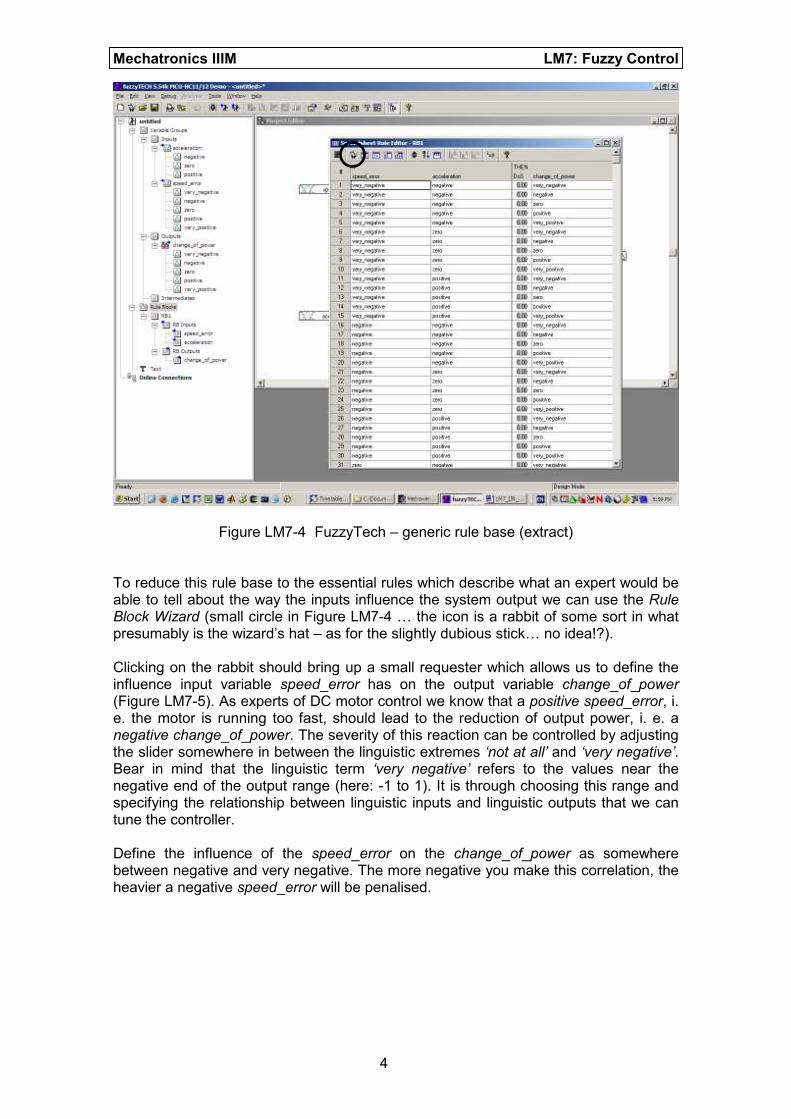
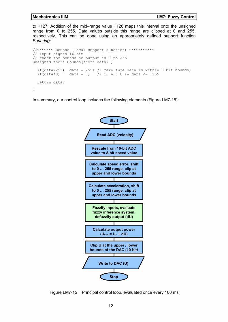
In summary, our control loop includes the following elements (Figure LM7-15):
Figure LM7-15 Principal control loop, evaluated once every 100 ms
Read ADC (velocity)
Write to DAC (U)
Rescale from 10-bit ADC
value to 8-bit speed value
Calculate speed error, shift
to 0 … 255 range, clip at
upper and lower bounds
Calculate acceleration, shift
to 0 … 255 range, clip at
upper and lower bounds
Fuzzify inputs, evaluate
fuzzy inference system,
defuzzify output (dU)
Calculate output power
(Uk+1 = Uk + dU)
Clip U at the upper / lower
bounds of the DAC (10-bit)
Start
Stop

Mechatronics IIIM LM7: Fuzzy Control
13
Fuzzification, fuzzy inference and defuzzification (green box in Figure LM7-15) are dealt with by a short assembler program (FuzzyEngine.asm). This program implements function FuzzyLogic:
FuzzyLogic: pshx pshb ldaa 6,sp ; RegA=SpeedError, 0 to 255 ldx #s_tab ldy #fuzvar mem
mem
mem
mem
mem
pula ;RegA=Acceleration, 0 to 255 ldx #a_tab mem
mem
mem
ldab #5 ; number of output fuzzy membership sets cloop: clr 1,y+ ; clear output fuzzy variables dbne b,cloop ldx #rules ldy #fuzvar ldaa #$FF rev
ldy #fuzout ldx #output_singletons ldab #5 wav
ediv ; Y has weighted average, 0 to 255 leay -128,y ; adjust for offset, -128 to +127 tfr y,d ; return dpower pulx rts
FuzzyLogic has two call-up parameters (speed_error, acceleration) and one return value (change_of_power). All parameters are passed from/to the calling function (e.g. main) to/from FuzzyLogic via the user stack. FuzzyLogic makes use of the special fuzzy logic instructions MEM, REV and WAV to fuzzify inputs, evaluate the rule base and defuzzify the output variables. The exact details of this assembler program are not too important to us. However, we do have to understand how the special fuzzy instructions work in general. This will enable us to define linguistic terms and a rule base which represents the results of our fuzzyTECH simulation. To make life a little easier you can download an incomplete fuzzy control project from myUni:
Mechatronics IIIM ջ Course Documents ջ Tutorials ջ 9S12 ջ fuzzy Load this project into the CodeWarrior IDE and open source code file fuzzyEngine.asm. At the beginning of this file you will find two lookup tables which define the membership functions and linguistic terms of both inputs as well as the output variable:

Mechatronics IIIM LM7: Fuzzy Control
14
; ------------------------------------------------------------- ; Fuzzy Membership sets ; ------------------------------------------------------------- ; input membership variables absentry fuzvar fuzvar: ds.b 8 ; inputs spErr_very_neg: equ 0 ; speed error very negative spErr_negative: equ 1 ; speed error negative spErr_zero: equ 2 ; speed error zero spErr_positive: equ 3 ; speed error positive spErr_very_pos: equ 4 ; speed error very positive accel_negative: equ 5 ; acceleration negative accel_zero: equ 6 ; acceleration zero accel_positive: equ 7 ; acceleration positive ;output membership variables absentry fuzout fuzout: ds.b 5 ; outputs power_bigsub: equ 8 ; subtract some power from system power_sub: equ 9 ; subtract some power from system power_zero: equ 10 ; leave power as is power_add: equ 11 ; add some power to system power_bigadd: equ 12 ; add a lot of power to system ; -------------------------------------------------------------
The input variable (fuzvar) is an array of 8 bytes, representing the 5 linguistic terms of speed_error (spErr_very_neg, spErr_negative, spErr_zero, spErr_positive, spErr_very_positive) followed by the 3 linguistic terms of acceleration (accel_negative, accel_zero, accel_positve). The output variable fuzout represents the change_of_power with its 5 linguistic terms power_bigsub, power_sub, power_zero, power_add and power_bigadd. All linguistic terms are assigned an individual identification number (0, 1, … 12). This section is relatively generic. You can use it without any further modifications. The next section defines the shape of all input membership functions. Each line of lookup table s_tab corresponds to one of the membership functions of speed_error. Each line in lookup table a_tab defines a membership function of acceleration. As it will be your task to define these membership functions, they have been left blank:
; ------------------------------------------------------------- ; fuzzification ; ------------------------------------------------------------- ; to be completed ... s_tab: dc.b ___, ___, ___, ___ ; spErr_very_neg dc.b ___, ___, ___, ___ ; spErr_negative dc.b ___, ___, ___, ___ ; spErr_zero dc.b ___, ___, ___, ___ ; spErr_positive dc.b ___, ___, ___, ___ ; spErr_very_pos a_tab: dc.b 0, 128, 0, 8 ; accel_negative dc.b ___, ___, ___, ___ ; accel_zero dc.b ___, ___, ___, ___ ; accel_positive ; ... to be completed ; -------------------------------------------------------------
According to the reference manual of the microcontroller (S12CPUV2, section 9, ‘Fuzzy Logic Support’) a membership function is defined by two points and two slopes. This allows for trapezoidal membership functions (̉-type MSF), Z-shaped/S-shaped MSF as well as triangular shaped MSF (ˤ-type). Figure LM7-16 presents the general case of a trapezoidal MSF.

Mechatronics IIIM LM7: Fuzzy Control
15
Figure LM7-16 Defining membership functions on the MC9S12DP256B/C The lookup table entries of a MSF are thus the x-position of point_1, the x-position of point_2, slope_1 ($FF/(x-position of saturation point – x-position of point_1) and slope_2 ($FF/(x-position of point_2 – x-position of saturation point). In the example shown in Figure LM7-16 slope_1 is derived as follows
( )08$897.732
255
20$
$
40$60$
$1_ =≈===
−=
FFFFslope
Notice that this calculation will never lead to a slope value smaller than 1. The MC9S12DP256B/C recognizes this fact and re-assigns the unused slope value $00 to infinitely large slopes. It is thus possible to define crisp membership functions with vertical slopes. A number of combinations of point_1, point_2, slope_1 and slope_2 lead to abnormally shaped membership functions, e.g. when the two slopes meet before reaching the saturation level $FF. However, in this exercise we are not going to use abnormal membership functions. For more information about abnormal MSF see the user manual (S12CPUV2, chapter 9). Use the above definition of point_1, point_2, slope_1 and slope_2 to build a membership function lookup table for all linguistic terms of input variable speed_error (s_tab) as well as input variable acceleration (a_tab). For example, the linguistic term accel_negative of input variable acceleration can be defined as follows (see: Figure LM7-17):
a_tab: dc.b 0, 128, 0, 8 ; accel_negative ; (0,0), (128,0), inf, 255/(128-64)

Mechatronics IIIM LM7: Fuzzy Control
16
Figure LM7-17 MSF for linguistic term accel_negative The next section defines the rule base of the controller. An unlimited number of rules can be programmed. Each rule uses a fuzzy AND to combine an arbitrary number of antecedents (IF – terms). Corresponding output terms (consequents) are combined using a fuzzy OR. A special character ($FE) is used to separate antecedents from consequents. The rule table is terminated by another special character ($FF). Using the above linguistic terms the rule base takes the following form:
; ------------------------------------------------------------- ; rule base ; ------------------------------------------------------------- rules: ; to be completed ... dc.b spErr_very_neg, accel_negative, $FE, power_add, $FE ; (...) dc.b spErr_very_pos, accel_positive, $FE, power_sub, $FE dc.b $FF ; ... to be completed ; -------------------------------------------------------------
Complete this rule table to reflect the results of your fuzzyTECH simulation. The final section of our fuzzy controller takes care of the defuzzification of output variable change_of_power. The MC9S12DP256B/C uses the Centre-of-Maximum (CoM) method to arrive at crisp output values. A weighted average is computed of suitably chosen singleton values of all active output variables. The latter are to be defined by the programmer in an n-element lookup table, where n is the number of linguistic output terms. In our case, there are 5 such terms: power_bigsub, power_sub, zero, power_add, and power_bigadd. As before, the singleton values need to be defined with respect to the unsigned 8-bit range from 0 to 255.
; ------------------------------------------------------------- ; defuzzification ; ------------------------------------------------------------- output_singletons: ; MoM -- Mean of Maximum (using 0 ... 255 range) ; power_bigsub, power_sub, power_zero, power_add, power_bigadd dc.b (64-0)/2, 103, 128, 154, (255+190)/2 ; -------------------------------------------------------------
255
0
0 128 255 64
accel_negative
slope_1 = 0 (ջ infinity)
slope_2 = 255/(128-64) = 8
point_1 point_2

Mechatronics IIIM LM7: Fuzzy Control
17
Modify lookup table output_singletons to reflect the centres of the linguistic output terms of your fuzzyTECH simulation. This concludes the specification of the fuzzy controller. Remark: The labels used in source file FuzzyEngine.asm are all local to this file. This means that you can choose to name your linguistic terms independently of the corresponding fuzzyTECH simulation. For example, in fuzzyTECH we used very_negative, negative, zero, positive and very_positive to characterise output variable change_of_power. The corresponding entries in FuzzyEngine.asm are: power_bigadd, power_add, zero, power_sub, and power_bigsub. However, once the source code is compiled, this naming inconsistency has vanished. The important thing is that a linguistic term matches the definition of its membership function, i. e. the first entry of fuzvar (spErr_very_negative) corresponds to the first entry of s_tab, etc. Test In this concluding section we will test or controller. Remember to take the power off the Dragon12 board whenever you change the wiring! The motor modules are driven by DC voltages ranging from 0 V to 2 V (pin 7). Voltages above 2 V do not increase the motor speed. A second DC motor is used as tachometer. It provides a feedback signal which is proportional to the current speed of the driven motor. The tachometer signal can vary between 0 V and 6 V. Figure LM7-18 shows a sketch of the motor module.
Figure LM7-18 Motor module We are now going to wire-up our speed control circuit. Before you begin, please take the power plug off the Dragon12 development board. Like many other HCMOS components, microcontrollers can be quite sensitive to short circuits which may occur when modifying the wiring of an electronic circuit. The template project has been prepared for receiving set-point information on ADC channel 7. Note that channel 7 is hardwired to the on-board potentiometer (range: 0 V to 5 V). Monitor the set-point signal on channel CH1 of the oscilloscope. Set the
Control signal
(0 V to 2 V)
Pin 7
Supply
(12 V DC)
Pin 1
PWM
M
T
GND
Pin 15
Tachometer
(0 V to 6 V)
Pins 3 (+), 4 (-)
(not grounded)

Mechatronics IIIM LM7: Fuzzy Control
18
corresponding vertical gain to 2 V/div and choose a reasonably slow horizontal gain (e.g. 500 ms/div). If you have not already done so, connect the communication lines SCL and SDA of the IIC bus interface to the corresponding pins of the D/A converter (DAC). You may also have to connect the power supply pins of the DAC to the corresponding connectors on the Dragon12 board. Two small wire loops on the left-hand side of the reset button give convenient access to VCC (5 V) as well as GND (0 V). Connect the output voltage of the D/A converter to the signal line of the motor module (pin 7). Monitor this signal on channel CH2 of the oscilloscope. Set the vertical gain to 2 V/div. Set the voltage of the laboratory power supply to 12 VDC, before switching it off. Never change the wiring of an electronic circuit while it is powered up. Provide the motor module with the required supply voltage of 12 V (pin 1: 12 V, pin 15: 0 V). Connect the ground of the power supply (GND) to the ground of the Dragon12 board. Connect pin 4 of the motor module (tachometer output, -ve) to the ground connector on the Dragon12. Finally, connect pin 3 (tachometer output, +ve) to channel 6 of the ADC unit of the MC9S12DP256B/C. This closes the loop of your control system (̅C ջ DAC ջ motor module ջ ADC ջ ̅C). You may want to use a suitably chosen voltage divider or a Zener diode to ensure that the interfaced voltage does not exceed 5 V.
Before you proceed, get the laboratory instructor to check the wiring of your circuit.
Power up the Dragon12 and download your program to the microcontroller using the CodeWarrior debugger. With the power supply of the motor module still switched off, click on start/resume to run the controller. Turn the set-point potentiometer to ensure it is actually operating in the expected range (0 V to 5 V). Set the voltage to somewhere between 0 V and 2 V (Figure LM7-19). Switch on the power supply of the DC motor module. The motor should start turning. Slowly change the set-point within the input range from 0 V to 2 V. If your controller works, the speed of the motor should follow your set-point profile (Figure LM7-20). Notice that the DAC signal never seems to reach the requested set-point voltage. This is due to the load presented by the input of the motor module. Switch off the motor power supply and remove the power of the Dragon12 board. Disconnect the wire from the DAC output to the signal pin of the motor module. Disconnect the wire from the tachometer output (+ve) to ADC channel 6. Use a small patch cable to directly connect the DAC output to ADC channel 6. Power up the Dragon12 board and run the control algorithm. Turn the potentiometer and observe the output signal of the controller. The DAC now reaches all values up to the limit of its output range (4 V). Depending on the exact shape of both membership functions as well as the rule base of your fuzzy controller you may observe a slight sluggishness (Figure LM21). This behaviour can be adjusted by changing the shapes and/or the centres of the input/output membership functions. Also bear in mind that the controller presented here does not make use of the linguistic variables power_bigadd and power_bigsub. A slightly more aggressive controller might exhibit a less sluggish dynamic response.

Mechatronics IIIM LM7: Fuzzy Control
19
Figure LM7-19 Testing the fuzzy controller – set-point (CH1)
Figure LM7-20 Testing the fuzzy controller – set-point (CH1), speed (CH2)

Mechatronics IIIM LM7: Fuzzy Control
20
Figure LM7-21 Testing the fuzzy controller – direct loop-back Concluding comments: The presented fuzzy control project includes the two support functions Bound and DAC_signedBound. The former simply ensures that a given input value is within the valid boundaries of an unsigned 8-bit variable. This function is used to clip input signals which are outside the range of the on-chip fuzzy support unit. The second function, DAC_signedBound, is a signed 10-bit equivalent which is used to limit a given input signal to the signed range from -512 to +511. LEDs 0 to 5 are used to indicate the level of the controller output signal (change_of_power) within the range -128 … 127. LEDs 6 and 7 are used to indicate DAC overflow (value > 1023) and underflow (value < 0), respectively. Finally, the controller evaluation time can be measured by producing pulse signals which indicate the duration of the timer interrupt service routine (see: timer.c). This has been done and the result is shown in Figures LM7-22 and LM7-23. If you are keen, you can replace the fuzzy inference engine (fuzzyEngine.asm) by one you programmed yourself. You will have to produce a function for fuzzification, one for the rule based fuzzy inference and a 3
rd function for defuzzification. Two support
functions, fuzzy_OR as well as fuzzy_AND, may also have to be written. Defining membership functions in C-structures will make the code much more accessible. However, you should be prepared for a significantly increased duration of the control cycle – even when trying to implement all major calculations using fast fixed point arithmetic.

Mechatronics IIIM LM7: Fuzzy Control
21
Figure LM7-22 Cycle time of the fuzzy control algorithm: approx. 200 ̅s
Figure LM7-23 Controller requires 2 % of the available 10 ms sample period