19. Mechatronic Systems – A Short Introduction Mechatronic S
15
317 Mechatronic 19. Mechatronic Systems – A Short Introduction Rolf Isermann Many technical processes and products in the area of mechanical and electrical engineering show increasing integration of mechanics with digital electronics and information processing. This in- tegration is between the components (hardware) and the information-driven functions (software), resulting in integrated systems called mechatronic systems. Their development involves finding an optimal balance between the basic mechanical structure, sensor and actuator implementation, and automatic information processing and overall control. Frequently formerly mechanical functions are replaced by electronically controlled func- tions, resulting in simpler mechanical structures and increased functionality. The development of mechatronic systems opens the door to many in- novative solutions and synergetic effects which are not possible with mechanics or electronics alone. This technical progress has a very strong in- fluence on a multitude of products in the areas of mechanical, electrical, and electronic engi- neering and is increasingly changing the design, for example, of conventional electromechanical components, machines, vehicles, and precision mechanical devices. 19.1 From Mechanical to Mechatronic Systems 317 19.2 Mechanical Systems and Mechatronic Developments ............. 319 19.2.1 Machine Elements, Mechanical Components ................................ 319 19.2.2 Electrical Drives and Servo Systems . 319 19.2.3 Power-Generating Machines ......... 320 19.2.4 Power-Consuming Machines ......... 320 19.2.5 Vehicles ...................................... 321 19.2.6 Trains ......................................... 321 19.3 Functions of Mechatronic Systems .......... 321 19.3.1 Basic Mechanical Design ............... 321 19.3.2 Distribution of Mechanical and Electronic Functions ............... 321 19.3.3 Operating Properties ..................... 322 19.3.4 New Functions ............................. 322 19.3.5 Other Developments ..................... 322 19.4 Integration Forms of Processes with Electronics .................................... 323 19.5 Design Procedures for Mechatronic Systems........................ 325 19.6 Computer-Aided Design of Mechatronic Systems ......................... 328 19.7 Conclusion and Emerging Trends ........... 329 References .................................................. 329 19.1 From Mechanical to Mechatronic Systems Mechanical systems generate certain motions or trans- fer forces or torques. For the oriented command of, e.g., displacements, velocities or forces, feedforward and feedback control systems have been applied for many years. The control systems operate either with- out auxiliary energy (e.g., a fly-ball governor), or with electrical, hydraulic or pneumatic auxiliary en- ergy, to manipulate the commanded variables directly or with a power amplifier. A realization with added fixed wired (analog) devices turns out to enable only relatively simple and limited control functions. If these analog devices are replaced with digital computers in the form of, e.g., online coupled microcomput- ers, the information processing can be designed to be considerably more flexible and more comprehen- sive. Figure 19.1 shows the example of a machine set, consisting of a power-generating machine (DC motor) and a power-consuming machine (circulation pump): (a) a scheme of the components, (b) the resulting sig- Part C 19
Transcript of 19. Mechatronic Systems – A Short Introduction Mechatronic S
317
Mechatronic S19. Mechatronic Systems – A Short Introduction
Rolf Isermann
Many technical processes and products in the areaof mechanical and electrical engineering showincreasing integration of mechanics with digitalelectronics and information processing. This in-tegration is between the components (hardware)and the information-driven functions (software),resulting in integrated systems called mechatronicsystems. Their development involves finding anoptimal balance between the basic mechanicalstructure, sensor and actuator implementation,and automatic information processing and overallcontrol. Frequently formerly mechanical functionsare replaced by electronically controlled func-tions, resulting in simpler mechanical structuresand increased functionality. The development ofmechatronic systems opens the door to many in-novative solutions and synergetic effects whichare not possible with mechanics or electronicsalone. This technical progress has a very strong in-fluence on a multitude of products in the areasof mechanical, electrical, and electronic engi-neering and is increasingly changing the design,for example, of conventional electromechanicalcomponents, machines, vehicles, and precisionmechanical devices.
19.1 From Mechanical to Mechatronic Systems 317
19.2 Mechanical Systemsand Mechatronic Developments ............. 31919.2.1 Machine Elements, Mechanical
Components ................................ 31919.2.2 Electrical Drives and Servo Systems . 31919.2.3 Power-Generating Machines ......... 32019.2.4 Power-Consuming Machines ......... 32019.2.5 Vehicles ...................................... 32119.2.6 Trains ......................................... 321
19.3 Functions of Mechatronic Systems .......... 32119.3.1 Basic Mechanical Design ............... 32119.3.2 Distribution of Mechanical
and Electronic Functions ............... 32119.3.3 Operating Properties ..................... 32219.3.4 New Functions ............................. 32219.3.5 Other Developments ..................... 322
19.4 Integration Forms of Processeswith Electronics.................................... 323
19.5 Design Proceduresfor Mechatronic Systems........................ 325
19.6 Computer-Aided Designof Mechatronic Systems ......................... 328
19.7 Conclusion and Emerging Trends ........... 329
References .................................................. 329
19.1 From Mechanical to Mechatronic Systems
Mechanical systems generate certain motions or trans-fer forces or torques. For the oriented command of,e.g., displacements, velocities or forces, feedforwardand feedback control systems have been applied formany years. The control systems operate either with-out auxiliary energy (e.g., a fly-ball governor), orwith electrical, hydraulic or pneumatic auxiliary en-ergy, to manipulate the commanded variables directlyor with a power amplifier. A realization with addedfixed wired (analog) devices turns out to enable only
relatively simple and limited control functions. If theseanalog devices are replaced with digital computersin the form of, e.g., online coupled microcomput-ers, the information processing can be designed tobe considerably more flexible and more comprehen-sive.
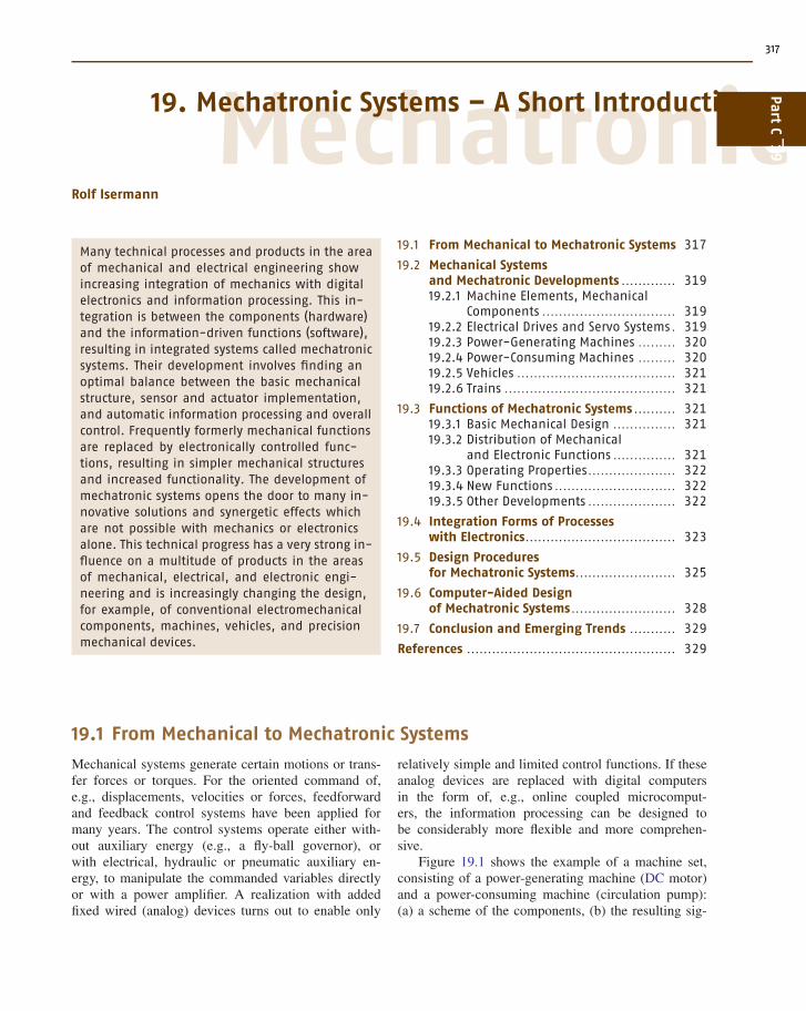
Figure 19.1 shows the example of a machine set,consisting of a power-generating machine (DC motor)and a power-consuming machine (circulation pump):(a) a scheme of the components, (b) the resulting sig-
PartC
19
318 Part C Automation Design: Theory, Elements, and Methods
Manipulated
variables
Measured
variablesSensorsActuator
Powerelectronics(actuator)
Powergeneratingmachine
(DC motor)
Powerconsuming
machine(pump)
Drivetrain(gearunit)
A
V
V
I
PGM PCMDT
Auxiliaryenergysupply
Energysupply
Energyconsumer
Primaryenergyflow Pi
Consumerenergy flow Po
PoPi
IA T1 T2 T3
VA ω1
ω1
ω2
ω2
ω3
ω3
Mechanics &energy converter
Energy flowc)
b)
a)
Energy flow
Information flow
SensorsActuators
Auxiliaryenergysupply
Energysupply
Energyconsumer
Primaryenergy
flow
Consumerenergy flow
Mechanics &energy converter
ReferencevariablesMonitored
variables
Manipulatedvariables
Measuredvariables
Informationprocessing
Man/machineinterface
Mechanical,hydraulic,thermal,electrical
Fig. 19.1a–c Schematic representation of a machine set:(a) scheme of the components; (b) signal flow diagram(two-port representation); (c) open-loop process. V – volt-age; VA – armature voltage; IA – armature current; T –torque; ω – angular frequency; Pi – drive power; Po –consumer power�
nal flow diagram in two-port representation, and (c)the open-loop process with one or several manipulatedvariables as input variables and several measured vari-ables as output variables. This process is characterizedby different controllable energy flows (electrical, me-chanical, and hydraulic). The first and last flow can bemanipulated by a manipulated variable of low power(auxiliary power), e.g., through a power electronics de-vice and a flow valve actuator. Several sensors yieldmeasurable variables. For a mechanical–electronic sys-tem, a digital electronic system is added to the process.This electronic system acts on the process based on themeasurements or external command variables in a feed-forward or feedback manner (Fig. 19.2). If then theelectronic and the mechanical system are merged to anautonomous overall system, an integrated mechanical–electronic system results. The electronics processesinformation, and such a system is characterized at leastby a mechanical energy flow and an information flow.
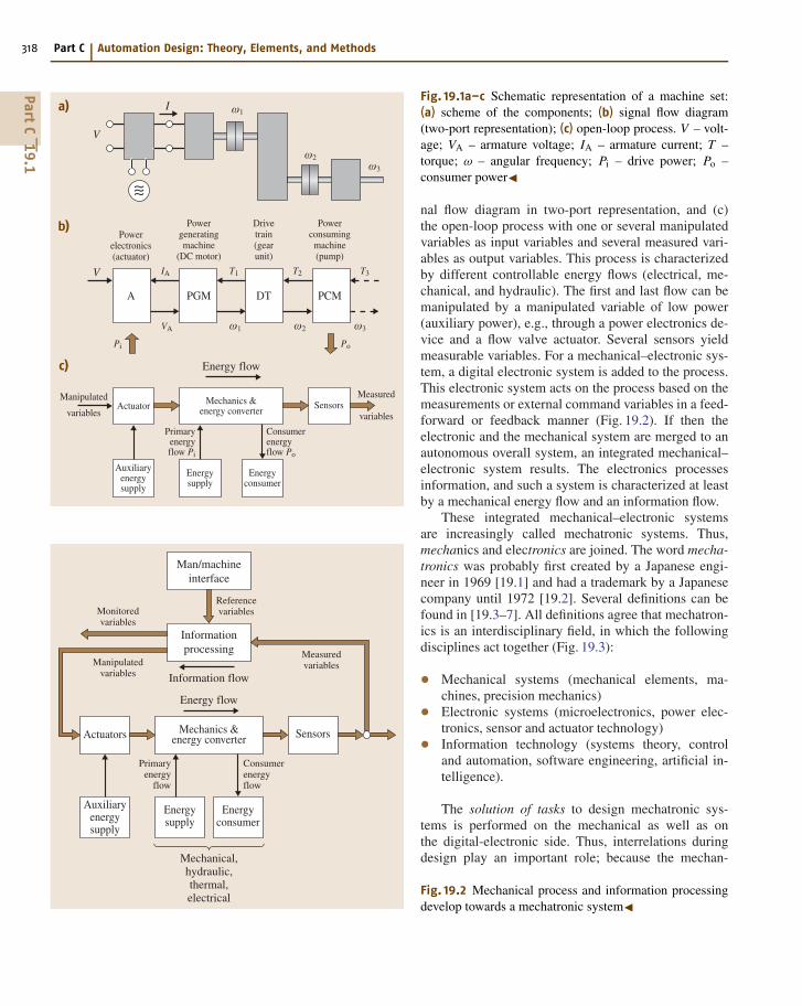
These integrated mechanical–electronic systemsare increasingly called mechatronic systems. Thus,mechanics and electronics are joined. The word mecha-tronics was probably first created by a Japanese engi-neer in 1969 [19.1] and had a trademark by a Japanesecompany until 1972 [19.2]. Several definitions can befound in [19.3–7]. All definitions agree that mechatron-ics is an interdisciplinary field, in which the followingdisciplines act together (Fig. 19.3):
• Mechanical systems (mechanical elements, ma-chines, precision mechanics)• Electronic systems (microelectronics, power elec-tronics, sensor and actuator technology)• Information technology (systems theory, controland automation, software engineering, artificial in-telligence).
The solution of tasks to design mechatronic sys-tems is performed on the mechanical as well as onthe digital-electronic side. Thus, interrelations duringdesign play an important role; because the mechan-
Fig. 19.2 Mechanical process and information processingdevelop towards a mechatronic system�
PartC
19.1
Mechatronic Systems – A Short Introduction 19.2 Mechanical Systems and Mechatronic Developments 319
Fig. 19.3 Mechatronics: synergetic integration of differentdisciplines�
ical system influences the electronic system, andvice versa, the electronic system influences the de-sign of the mechanical system (Fig. 19.4). This meansthat simultaneous engineering has to take place, withthe goal of designing an overall integrated sys-tem (an organic system) and also creating synergeticeffects.
A further feature of mechatronic systems is in-tegrated digital information processing. As well asbasic control functions, more sophisticated controlfunctions may be realized, e.g., calculation of nonmea-surable variables, adaptation of controller parameters,detection and diagnosis of faults and, in the case of fail-ures, reconfiguration to redundant components. Hence,mechatronic systems are developing with adaptive oreven learning behavior, which can also be called intelli-gent mechatronic systems.
The developments to date can be found in [19.2,7–11]. An insight into general aspects are given ed-itorially in journals [19.5, 6], conference proceedingssuch as [19.12–17], journal articles by [19.18–21], andbooks [19.22–27]. A summary of research projects atthe Darmstadt University of Technology can be foundin [19.28].
Electronics Informationtechnology
System theoryModelingAutomation-technologySofwareArtificial intelligence
Mechanical elementsMachinesPrecision mechanicsElectrical elements
Micro electronicsPower electronicsSensorsActuators Mecha-
tronics
Mechanics&
electro-mechanics
Designconstruction
Separate components
Conventional procedurea) Mechatronic procedureb)
Mechan.system
Electronics
Designconstruction
Mechatronic overall system
Mechan.system
Electron.system
Fig. 19.4a,b Interrelations during the design and construction ofmechatronic systems
19.2 Mechanical Systems and Mechatronic Developments
Mechanical systems can be applied to a large areaof mechanical engineering. According to their con-struction, they can be subdivided into mechanicalcomponents, machines, vehicles, precision mechanicaldevices, and micromechanical components.
The design of mechanical products is influenced bythe interplay of energy, matter, and information. Withregard to the basic problem and its solution, frequentlyeither the energy, matter or information flow is dom-inant. Therefore, one main flow and at least one sideflow can be distinguished [19.29].
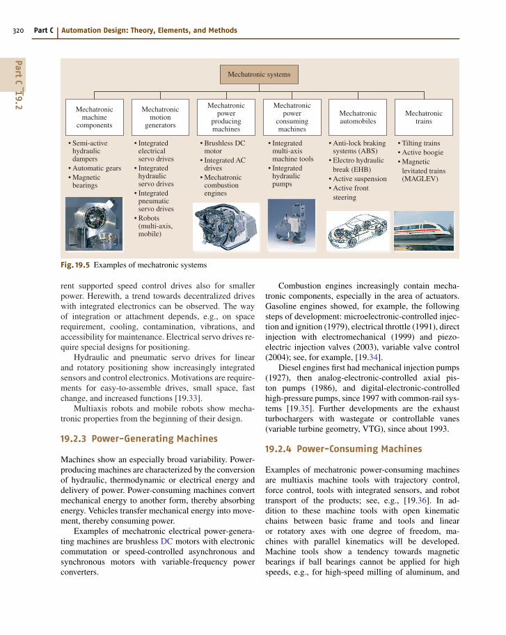
In the following some examples of mechatronicdevelopments are given. The area of mechanical com-ponents, machines, and vehicles is covered by Fig. 19.5.
19.2.1 Machine Elements, MechanicalComponents
Machine elements are usually purely mechanical. Fig-ure 19.5 shows some examples. Properties that can be
improved by electronics are, for example, self-adaptivestiffness and damping, self-adaptive free motion orpretension, automatic operating functions such as cou-pling or gear shifting, and supervisory functions.Some examples of mechatronic approaches are hy-drobearings for combustion engines with electroniccontrol of damping, magnetic bearings with posi-tion control [19.30], automatic electronic–hydraulicgears [19.31], and adaptive shock absorbers for wheelsuspensions [19.32].
19.2.2 Electrical Drives and Servo Systems
Electrical drives with direct-current, universal, asyn-chronous, and synchronous motors have used inte-gration with gears, speed sensors or position sensorsand power electronics for many years. Especially thedevelopment of transistor-based voltage supplies andcheaper power electronics on the basis of transistorsand thyristors with variable-frequency three-phase cur-
PartC
19.2
320 Part C Automation Design: Theory, Elements, and Methods
Mechatronic systems
Mechatronicmachine
components
• Semi-active hydraulic dampers• Automatic gears• Magnetic bearings
Mechatronicmotion
generators
• Integrated electrical servo drives• Integrated hydraulic servo drives• Integrated pneumatic servo drives• Robots (multi-axis, mobile)
Mechatronicpower
producingmachines
• Brushless DC motor• Integrated AC drives• Mechatronic combustion engines
Mechatronicpower
consumingmachines
• Integrated multi-axis machine tools• Integrated hydraulic pumps
Mechatronicautomobiles
• Anti-lock braking systems (ABS)• Electro hydraulic break (EHB)• Active suspension• Active front steering
Mechatronictrains
• Tilting trains• Active boogie• Magnetic levitated trains (MAGLEV)
Fig. 19.5 Examples of mechatronic systems
rent supported speed control drives also for smallerpower. Herewith, a trend towards decentralized driveswith integrated electronics can be observed. The wayof integration or attachment depends, e.g., on spacerequirement, cooling, contamination, vibrations, andaccessibility for maintenance. Electrical servo drives re-quire special designs for positioning.
Hydraulic and pneumatic servo drives for linearand rotatory positioning show increasingly integratedsensors and control electronics. Motivations are require-ments for easy-to-assemble drives, small space, fastchange, and increased functions [19.33].
Multiaxis robots and mobile robots show mecha-tronic properties from the beginning of their design.
19.2.3 Power-Generating Machines
Machines show an especially broad variability. Power-producing machines are characterized by the conversionof hydraulic, thermodynamic or electrical energy anddelivery of power. Power-consuming machines convertmechanical energy to another form, thereby absorbingenergy. Vehicles transfer mechanical energy into move-ment, thereby consuming power.
Examples of mechatronic electrical power-genera-ting machines are brushless DC motors with electroniccommutation or speed-controlled asynchronous andsynchronous motors with variable-frequency powerconverters.
Combustion engines increasingly contain mecha-tronic components, especially in the area of actuators.Gasoline engines showed, for example, the followingsteps of development: microelectronic-controlled injec-tion and ignition (1979), electrical throttle (1991), directinjection with electromechanical (1999) and piezo-electric injection valves (2003), variable valve control(2004); see, for example, [19.34].
Diesel engines first had mechanical injection pumps(1927), then analog-electronic-controlled axial pis-ton pumps (1986), and digital-electronic-controlledhigh-pressure pumps, since 1997 with common-rail sys-tems [19.35]. Further developments are the exhaustturbochargers with wastegate or controllable vanes(variable turbine geometry, VTG), since about 1993.
19.2.4 Power-Consuming Machines
Examples of mechatronic power-consuming machinesare multiaxis machine tools with trajectory control,force control, tools with integrated sensors, and robottransport of the products; see, e.g., [19.36]. In ad-dition to these machine tools with open kinematicchains between basic frame and tools and linearor rotatory axes with one degree of freedom, ma-chines with parallel kinematics will be developed.Machine tools show a tendency towards magneticbearings if ball bearings cannot be applied for highspeeds, e.g., for high-speed milling of aluminum, and
PartC
19.2
Mechatronic Systems – A Short Introduction 19.3 Functions of Mechatronic Systems 321
also for ultracentrifuges [19.37]. Within the area ofmanufacturing, many machinery, sorting, and trans-portation devices are characterized by integrationwith electronics, but as yet they are mostly notfully hardware-integrated. For hydraulic piston pumpsthe control electronics is now attached to the cas-ing [19.33]. Further examples are packing machineswith decentralized drives and trajectory control oroffset-printing machines with replacement of the me-chanical synchronization axis through decentralizeddrives with digital electronic synchronization and highprecision.
19.2.5 Vehicles
Many mechatronic components have been introduced,especially in the area of vehicles, or are in development:antilock braking control (ABS) [19.38], controllableshock absorbers [19.39], controlled adaptive suspen-sions [19.40], active suspensions [19.41, 42], drivedynamic control through individual braking (electronic
stability program, ESP) [19.43, 44], electrohydraulicbrakes (2001), and active front steering (AFS) (2003).Of the innovations for vehicles 80–90% are based onelectronic/mechatronic developments. Here, the valueof electronics/electrics of vehicles increases to about30% or more.
19.2.6 Trains
Trains with steam, diesel or electrical locomotives havefollowed a very long development. For wagons the de-sign with two boogies with two axes are standard. ABSbraking control can be seen as the first mechatronic in-fluence in this area [19.45, 46]. The high-speed trains(TGV, ICE) contain modern asynchronous motors withpower electronic control. The trolleys are supplied withelectronic force and position control. Tilting trains showa mechatronic design (1997) and actively damped andsteerable boogies also [19.47]. Further, magneticallylevitated trains are based on mechatronic construction;see, e.g., [19.47].
19.3 Functions of Mechatronic Systems
Mechatronic systems enable, after the integration of thecomponents, many improved and also new functions.This will be discussed by using examples.
19.3.1 Basic Mechanical Design
The basic mechanical construction first has to satisfy thetask of transferring the mechanical energy flow (force,torque) to generate motions or special movements, etc.Known traditional methods are applied, such as materialselection, calculation of strengths, manufacturing, pro-duction costs, etc. By attaching sensors, actuators, andmechanical controllers, in earlier times, simple controlfunctions were realized, e.g., the fly-ball governor. Thengradually pneumatic, hydraulic, and electrical analogcontrollers were introduced. After the advent of digitalcontrol systems, especially with the development of mi-croprocessors around 1975, the information processingpart could be designed to be much more sophisticated.These digitally controlled systems were first added tothe basic mechanical construction and were limitedby the properties of the sensors, actuators, and elec-tronics, i. e., they frequently did not satisfy reliabilityand lifetime requirements under rough environmen-tal conditions (temperature, vibrations, contamination)
and had a relatively large space requirement and cableconnections, and low computational speed. However,many of these initial drawbacks were removed withtime, and since about 1980 electronic hardware has be-come greatly miniaturized, robust, and powerful, andhas been connected by field bus systems. Based on this,the emphasis on the electronic side could be increasedand the mechanical construction could be designed asa mechanical–electronic system from the very begin-ning. The aim was to result in more autonomy, forexample, by decentralized control, field bus connec-tions, plug-and-play approaches, and distributed energysupply, such that self-contained units emerge.
19.3.2 Distribution of Mechanicaland Electronic Functions
In the design of mechatronic systems, interplay for therealization of functions in the mechanical and elec-tronic parts is crucial. Compared with pure mechanicalrealizations, the use of amplifiers and actuators withelectrical auxiliary energy has already led to con-siderable simplifications, as can be seen in watches,electronic typewriters, and cameras. A further consid-erable simplification in the mechanics resulted from
PartC
19.3
322 Part C Automation Design: Theory, Elements, and Methods
the introduction of microcomputers in connection withdecentralized electrical drives, e.g., for electronic type-writers, sewing machines, multiaxis handling systems,and automatic gears.
The design of lightweight constructions leads toelastic systems that are weakly damped through thematerial itself. Electronic damping through position,speed or vibration sensors and electronic feedbackcan be realized with the additional advantage of ad-justable damping through algorithms. Examples areelastic drive trains of vehicles with damping algorithmsin the engine electronics, elastic robots, hydraulic sys-tems, far-reaching cranes, and space constructions (e.g.,with flywheels).
The addition of closed-loop control, e.g., for po-sition, speed or force, does not only result in precisetracking of reference variables, but also an approxi-mate linear overall behavior, even though mechanicalsystems may show nonlinear behavior. By omitting theconstraint of linearization on the mechanical side, theeffort for construction and manufacturing may be re-duced. Examples are simple mechanical pneumatic andelectromechanical actuators and flow valves with elec-tronic control.
With the aid of freely programmable referencevariable generation, the adaptation of nonlinear me-chanical systems to the operator can be improved.This is already used for driving-pedal characteristicswithin engine electronics for automobiles, telemanipu-lation of vehicles and aircraft, and in the developmentof hydraulically actuated excavators and electric powersteering.
However, with increasing number of sensors, ac-tuators, switches, and control units, the cables andelectrical connections also increase, such that reliabil-ity, cost, weight, and required space are major concerns.Therefore, the development of suitable bus systems,plug systems, and fault-tolerant and reconfigurable elec-tronic systems are challenges for the designer.
19.3.3 Operating Properties
By applying active feedback control, the precision of,e.g., a position is reached by comparison of a pro-grammed reference variable with a measured controlvariable and not only through the high mechanical pre-cision of a passively feedforward-controlled mechanicalelement. Therefore, the mechanical precision in designand manufacturing may be reduced somewhat and sim-pler constructions for bearings or slideways can be used.An important aspect in this regard is compensation
of larger and time-variant friction by adaptive frictioncompensation. Larger friction at the cost of backlashmay also be intended (e.g., gears with pretension), be-cause it is usually easier to compensate for frictionthan for backlash. Model-based and adaptive controlallow operation at more operating points (wide-rangeoperation) compared with fixed control with unsatis-factory performance (danger of instability or sluggishbehavior). A combination of robust and adaptive con-trol enables wide-range operation, e.g., for flow, force,and speed control, and for processes involving engines,vehicles, and aircraft. Better control performance al-lows the reference variables to be moved closer toconstraints with improved efficiencies and yields (e.g.,higher temperatures, pressures for combustion enginesand turbines, compressors at stalling limits, and highertensions and higher speed for paper machines and steelmills).
19.3.4 New Functions
Mechatronic systems also enable functions that couldnot be performed without digital electronics. Firstly,nonmeasurable quantities can be calculated on thebasis of measured signals and influenced by feedfor-ward or feedback control. Examples are time-dependentvariables such as the slip for tires, internal tensions,temperatures, the slip angle and ground speed for steer-ing control of vehicles or parameters such as dampingand stiffness coefficients, and resistances. The auto-matic adaptation of parameters, such as damping andstiffness for oscillating systems based on measurementsof displacements or accelerations, is another example.Integrated supervision and fault diagnosis becomes in-creasingly important with more automatic functions,increasing complexity, and higher demands on relia-bility and safety. Then, fault tolerance by triggeringof redundant components and system reconfiguration,maintenance on request, and any kind of teleservicemakes the system more intelligent.
19.3.5 Other Developments
Mechatronic systems frequently allow flexible adapta-tion to boundary conditions. A part of the functionsand also precision becomes programmable and rapidlychangeable. Advanced simulations enable the reductionof experimental investigations with many parametervariations. Also, shorter time to market is possible ifthe basic elements are developed in parallel and thefunctional integration results from the software.
PartC
19.3
Mechatronic Systems – A Short Introduction 19.4 Integration Forms of Processes with Electronics 323
Table 19.1 Some properties of conventional and mechatronic designed systems
Conventional design Mechatronic design
Added components Integration of components (hardware)
Bulky Compact
Complex Simple mechanisms
Cable problems Bus or wireless communication
Connected components Autonomous units
Simple control Integration by information processing (software)
Stiff construction Elastic construction with damping by electronic feedback
Feedforward control, linear (analog) control Programmable feedback (nonlinear) digital control
Precision through narrow tolerances Precision through measurement and feedback control
Nonmeasurable quantities change arbitrarily Control of nonmeasurable estimated quantities
Simple monitoring Supervision with fault diagnosis
Fixed abilities Adaptive and learning abilities
A far-reaching integration of the process and theelectronics is much easier if the customer obtains thefunctioning system from one manufacturer. Usually,this is the manufacturer of the machine, the device orthe apparatus. Although these manufacturers have to in-vest a lot of effort in coping with the electronics andthe information processing, they gain the chance to addto the value of the product. For small devices and ma-
chines with large production numbers, this is obvious.In the case of larger machines and apparatus, the pro-cess and its automation frequently comes from differentmanufacturers. Then, special effort is needed to produceintegrated solutions.
Table 19.1 summarizes some properties of mecha-tronic systems compared with conventional electrome-chanical systems.
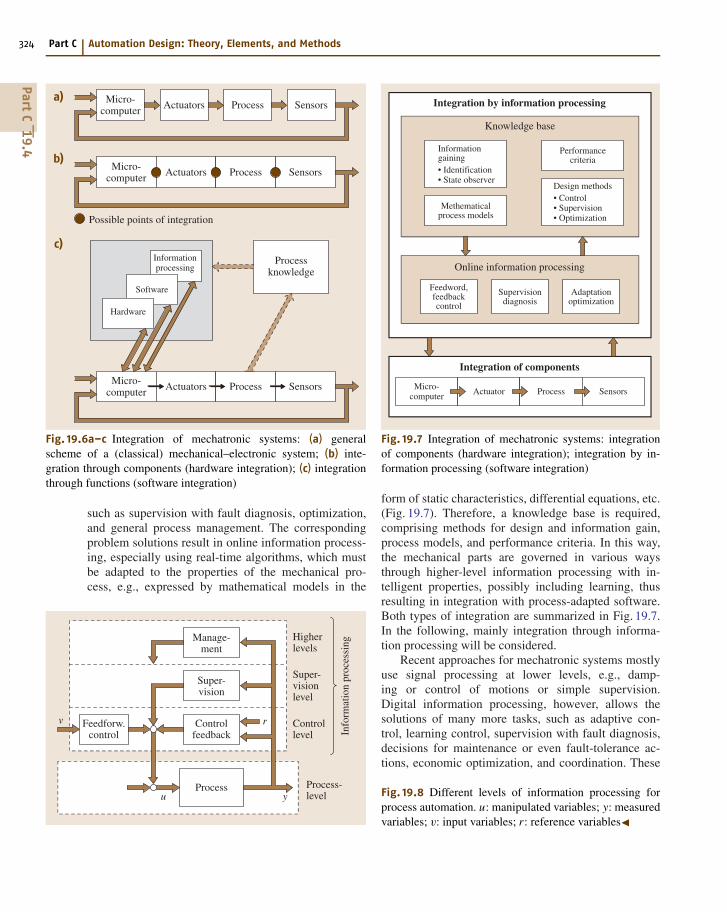
19.4 Integration Forms of Processes with Electronics
Figure 19.6a shows a general scheme of a classicalmechanical–electronic system. Such systems resultedfrom adding available sensors and actuators and ana-log or digital controllers to the mechanical components.The limits of this approach were the lack of suit-able sensors and actuators, unsatisfactory lifetime underrough operating conditions (acceleration, temperature,and contamination), large space requirements, the re-quired cables, and relatively slow data processing.With increasing improvements in the miniaturization,robustness, and computing power of microelectroniccomponents, one can now try to place more emphasis onthe electronic side and design the mechanical part fromthe beginning with a view to a mechatronic overall sys-tem. Then, more autonomous systems can be envisaged,e.g., in the form of encapsulated units with noncon-tacting signal transfer or bus connections and robustmicroelectronics.
Integration within a mechatronic system can be per-formed mainly in two ways: through the integrationof components and through integration by informationprocessing (see also Table 19.1).
The integration of components (hardware integra-tion) results from designing the mechatronic system asan overall system and embedding the sensors, actua-tors, and microcomputers into the mechanical process(Fig. 19.6b). This spatial integration may be limited tothe process and sensor or the process and actuator.The microcomputers can be integrated with the actu-ator, the process or sensor, or be arranged at severalplaces. Integrated sensors and microcomputers lead tosmart sensors, and integrated actuators and microcom-puters develop into smart actuators. For larger systems,bus connections will replace the many cables. Hence,there are several possibilities for building an integratedoverall system by proper integration of the hardware.
Integration by information processing (softwareintegration) is mostly based on advanced control func-tions. Besides basic feedforward and feedback control,an additional influence may take place through pro-cess knowledge and corresponding online informationprocessing (Fig. 19.6c). This means processing of avail-able signals at higher levels, as will be discussed inthe next Section. This includes the solution of tasks
PartC
19.4
324 Part C Automation Design: Theory, Elements, and Methods
Micro-computer
a)
b)
Actuators Process Sensors
Micro-computer Actuators Process Sensors
Possible points of integration
c)
Micro-computer Actuators Process Sensors
Processknowledge
Hardware
Software
Informationprocessing
Fig. 19.6a–c Integration of mechatronic systems: (a) generalscheme of a (classical) mechanical–electronic system; (b) inte-gration through components (hardware integration); (c) integrationthrough functions (software integration)
such as supervision with fault diagnosis, optimization,and general process management. The correspondingproblem solutions result in online information process-ing, especially using real-time algorithms, which mustbe adapted to the properties of the mechanical pro-cess, e.g., expressed by mathematical models in the
Controlfeedback
Super-vision
Info
rmat
ion
proc
essi
ng
Process
Manage-ment
Higherlevels
Super-visionlevel
Controllevel
Process-level
Feedforw.control
v
u y
r
Methematicalprocess models
Informationgaining• Identification• State observer
Performancecriteria
Design methods• Control• Supervision• Optimization
Feedword,feedbackcontrol
Supervisiondiagnosis
Adaptationoptimization
Integration of components
Integration by information processing
Online information processing
Knowledge base
Micro-computer Actuator Process Sensors
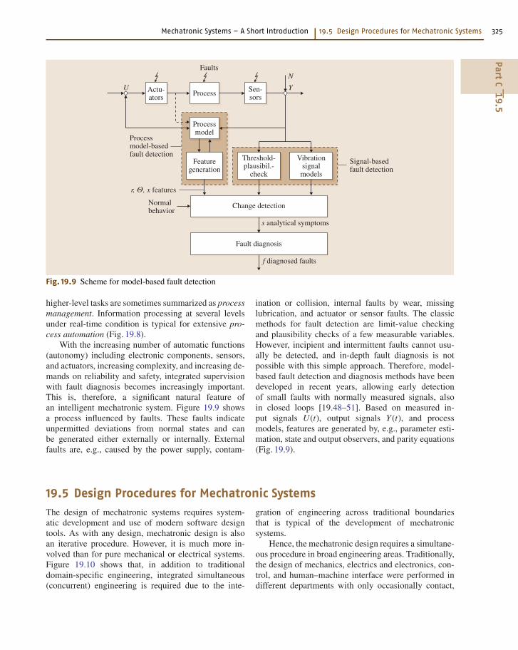
Fig. 19.7 Integration of mechatronic systems: integrationof components (hardware integration); integration by in-formation processing (software integration)
form of static characteristics, differential equations, etc.(Fig. 19.7). Therefore, a knowledge base is required,comprising methods for design and information gain,process models, and performance criteria. In this way,the mechanical parts are governed in various waysthrough higher-level information processing with in-telligent properties, possibly including learning, thusresulting in integration with process-adapted software.Both types of integration are summarized in Fig. 19.7.In the following, mainly integration through informa-tion processing will be considered.
Recent approaches for mechatronic systems mostlyuse signal processing at lower levels, e.g., damp-ing or control of motions or simple supervision.Digital information processing, however, allows thesolutions of many more tasks, such as adaptive con-trol, learning control, supervision with fault diagnosis,decisions for maintenance or even fault-tolerance ac-tions, economic optimization, and coordination. These
Fig. 19.8 Different levels of information processing forprocess automation. u: manipulated variables; y: measuredvariables; v: input variables; r: reference variables�
PartC
19.4
Mechatronic Systems – A Short Introduction 19.5 Design Procedures for Mechatronic Systems 325
Actu-ators
Signal-basedfault detection
s analytical symptoms
f diagnosed faults
Sen-sorsProcess
Processmodel
Featuregeneration
Threshold-plausibil.-
check
Change detection
Fault diagnosis
Vibrationsignalmodels
Processmodel-basedfault detection
Normalbehavior
Faults
U Y
r, Θ, x features
N
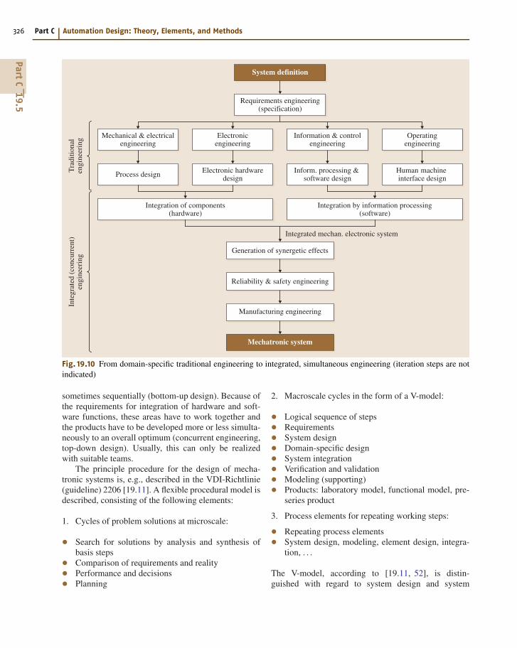
Fig. 19.9 Scheme for model-based fault detection
higher-level tasks are sometimes summarized as processmanagement. Information processing at several levelsunder real-time condition is typical for extensive pro-cess automation (Fig. 19.8).
With the increasing number of automatic functions(autonomy) including electronic components, sensors,and actuators, increasing complexity, and increasing de-mands on reliability and safety, integrated supervisionwith fault diagnosis becomes increasingly important.This is, therefore, a significant natural feature ofan intelligent mechatronic system. Figure 19.9 showsa process influenced by faults. These faults indicateunpermitted deviations from normal states and canbe generated either externally or internally. Externalfaults are, e.g., caused by the power supply, contam-
ination or collision, internal faults by wear, missinglubrication, and actuator or sensor faults. The classicmethods for fault detection are limit-value checkingand plausibility checks of a few measurable variables.However, incipient and intermittent faults cannot usu-ally be detected, and in-depth fault diagnosis is notpossible with this simple approach. Therefore, model-based fault detection and diagnosis methods have beendeveloped in recent years, allowing early detectionof small faults with normally measured signals, alsoin closed loops [19.48–51]. Based on measured in-put signals U(t), output signals Y (t), and processmodels, features are generated by, e.g., parameter esti-mation, state and output observers, and parity equations(Fig. 19.9).
19.5 Design Procedures for Mechatronic Systems
The design of mechatronic systems requires system-atic development and use of modern software designtools. As with any design, mechatronic design is alsoan iterative procedure. However, it is much more in-volved than for pure mechanical or electrical systems.Figure 19.10 shows that, in addition to traditionaldomain-specific engineering, integrated simultaneous(concurrent) engineering is required due to the inte-
gration of engineering across traditional boundariesthat is typical of the development of mechatronicsystems.
Hence, the mechatronic design requires a simultane-ous procedure in broad engineering areas. Traditionally,the design of mechanics, electrics and electronics, con-trol, and human–machine interface were performed indifferent departments with only occasionally contact,
PartC
19.5
326 Part C Automation Design: Theory, Elements, and Methods
System definition
Requirements engineering(specification)
Generation of synergetic effects
Integrated mechan. electronic system
Reliability & safety engineering
Manufacturing engineering
Mechatronic system
Electronicengineering
Mechanical & electricalengineering
Tra
ditio
nal
engi
neer
ing
Inte
grat
ed (
conc
urre
nt)
engi
neer
ing
Operatingengineering
Information & controlengineering
Electronic hardwaredesignProcess design Human machine
interface designInform. processing &
software design
Integration of components(hardware)
Integration by information processing(software)
Fig. 19.10 From domain-specific traditional engineering to integrated, simultaneous engineering (iteration steps are notindicated)
sometimes sequentially (bottom-up design). Because ofthe requirements for integration of hardware and soft-ware functions, these areas have to work together andthe products have to be developed more or less simulta-neously to an overall optimum (concurrent engineering,top-down design). Usually, this can only be realizedwith suitable teams.
The principle procedure for the design of mecha-tronic systems is, e.g., described in the VDI-Richtlinie(guideline) 2206 [19.11]. A flexible procedural model isdescribed, consisting of the following elements:
1. Cycles of problem solutions at microscale:
• Search for solutions by analysis and synthesis ofbasis steps• Comparison of requirements and reality• Performance and decisions• Planning
2. Macroscale cycles in the form of a V-model:
• Logical sequence of steps• Requirements• System design• Domain-specific design• System integration• Verification and validation• Modeling (supporting)• Products: laboratory model, functional model, pre-series product
3. Process elements for repeating working steps:
• Repeating process elements• System design, modeling, element design, integra-tion, . . .
The V-model, according to [19.11, 52], is distin-guished with regard to system design and system
PartC
19.5
Mechatronic Systems – A Short Introduction 19.5 Design Procedures for Mechatronic Systems 327
Degree of maturity
Validation
Requirements• Overall functions• Rated values• Costs & milestones
Specifications• Fulfillment of requirements• Sources, limitations• Reliability, safety
System design• Paritioning• Modules• Mechanics vs. electronics• Synergies
Modeling & simulation• Models of component• Behavior analysis• Requirements for components• Design
Prototypes• Laboratory solutions• Modifications former products• Prototype computers/algorithms
Component testing• Hardware-in-the-loop simulation• Stress analysis
System integration (hardware)• Assembling• Mutual adaption• Optimization• Synergies
System integration (software)• Signal analysis• Filtering• Tuning of algorithms
System testing• Test rigs• Stress testing, electromagnetic compatibility• Behavior testing• Reliability, safety
Field testing• Final product• Normal use• Statistics• Certification
Production• Simultaneous planning• Technologies• Assembling• Quality control
Mechatronic components• Mechanics• Electronics• Control-software• Human machine interface
Verification
Systemdesign
Systemintegration
Component design (domain specific)
Mechanics Electronics Automaticcontrol
Human machineinterface
Fig. 19.11 A “V” development scheme for mechatronic systems
integration with domain-specific design in mechani-cal engineering, electrical engineering, and informationprocessing. Usually, several design cycles are re-quired, resulting, e.g., in the following intermediateproducts:
• Laboratory model: first functions and solutions,rough design, first function-specific investigations• Functional model: further development, fine-tuning,integration of distributed components, power mea-surements, standard interfaces• Pre-series product: consideration of manufacturing,standardization, further modular integration steps,encapsulation, field tests.
The V-model originates most likely from softwaredevelopment [19.53]. Some important design steps for
mechatronic systems are shown in Fig. 19.11 in the formof an extended V-model, where the following are distin-guished: system design up to laboratory model, systemintegration up to functional model, and system tests upto pre-series product.
The maturity of the product increases as the individ-ual steps of the V-model are followed. However, severaliterations have to be performed, which is not illustratedin the figure.
Depending on the type of product, the degree ofmechatronic design is different. For precision mechanicdevices the integration is already well developed. In thecase of mechanical components one can use as a basiswell-proven constructions. Sensors, actuators, and elec-tronics can be integrated by corresponding changes, ascan be seen, e.g., in adaptive shock absorbers, hydraulicbrakes, and fluidic actuators. In machines and vehicles it
PartC
19.5
328 Part C Automation Design: Theory, Elements, and Methods
can be observed that the basic mechanical constructionremains constant but is complemented by mechatronic
components, as is the case for machine tools, combus-tion engines, and automobiles.
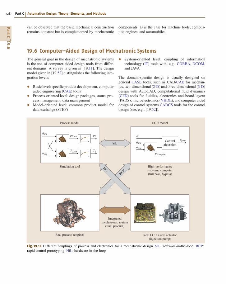
19.6 Computer-Aided Design of Mechatronic Systems
The general goal in the design of mechatronic systemsis the use of computer-aided design tools from differ-ent domains. A survey is given in [19.11]. The designmodel given in [19.52] distinguishes the following inte-gration levels:
• Basic level: specific product development, computer-aided engineering (CAE) tools• Process-oriented level: design packages, status, pro-cess management, data management• Model-oriented level: common product model fordata exchange (STEP)
Process model
Simulation tool High-performancereal-time computer(full pass, bypass)
Controlalgorithm
upwm
p2, setpoint
p2, stat
T2, stat
p2p2
T2
neng
neng
θFW
θFW
Real process (engine) Real ECU + real actuator(injection pump)
Integratedmechatronic system
(final product)
ECU model
SiL
HiLRCP
Fig. 19.12 Different couplings of process and electronics for a mechatronic design. SiL: software-in-the-loop; RCP:rapid control prototyping; HiL: hardware-in-the-loop
• System-oriented level: coupling of informationtechnology (IT) tools with, e.g., CORBA, DCOM,and JAVA
The domain-specific design is usually designed ongeneral CASE tools, such as CAD/CAE for mechan-ics, two-dimensional (2-D) and three-dimensional (3-D)design with AutoCAD, computational fluid dynamics(CFD) tools for fluidics, electronics and board-layout(PADS), microelectronics (VHDL), and computer aideddesign of control systems CADCS tools for the controldesign (see, e.g., [19.52]).
PartC
19.6
Mechatronic Systems – A Short Introduction References 329
For overall modeling, object-oriented software isespecially of interest based on the use of generalmodel-building laws. The models are first formulatedas noncausal objects installed in libraries. They are thencoupled with graphical support (object diagrams) byusing methods of herit and reusability.
Examples are MODELICA, MOBILE, VHDL-AMS, 20 SIM; see, e.g., [19.54–59]. A broadly usedtool for simulation and dynamics design is MAT-LAB/SIMULINK.
To design mechatronic systems various simulationenvironment models have been developed, as shown inthe V-model (Fig. 19.11). In the case of software-in-the-loop (SiL) simulation the process and its control issimulated in a higher language to carry out basic inves-tigations (Fig. 19.12). This does not require real-timesimulation and is directed towards consideration of gen-eral process behavior and control structure in an earlierstage to avoid too many prototypes.
If first mechatronic prototypes exist but the finalhardware of the control is missing, the rapid-control-prototyping (RCP) procedure can be used. In this,a mechatronic prototype operates as a real system witha simulated control on a test rig in order to test, e.g.,control algorithms under real conditions. The prototyp-ing computer is a powerful real-time computer withhigher-language programming.
Hardware-in-the-loop (HiL) simulation is used toperform various tests in a laboratory with final hardware(electronic control unit: ECU) and the final softwaretogether with the simulated process on a powerful com-puter. Through HiL simulation, extreme operationaland environmental conditions can also be investigated,along with faults and failures that cannot be realizedwith a real process on a test rig or a real vehicle, be-cause the situations would be either too dangerous ortoo expensive. HiL simulation requires special electron-ics for reconstruction of the sensor signals and usuallyincludes real actuators (e.g., hydraulics, pneumatics orinjection pumps). Through these simulation methodsthe development of mechatronic systems can be per-formed without synchronous development on the sideof the process, the electronics, or the software.
When designing mechatronic systems the tradi-tional borders of various disciplines have to be crossed.For the classical mechanical engineer this frequentlymeans that knowledge of electronic components, in-formation processing, and systems theory has to bedeepened, and for the electrical/electronic engineer thatknowledge on thermodynamics, fluid mechanics, andengineering mechanics has to be enlarged. For both,more knowledge on modern control principles, soft-ware engineering, and information technology may benecessary (see also [19.60]).
19.7 Conclusion and Emerging Trends
This Chapter could only give a brief overview ofmechatronic systems. As outlined, mechatronic sys-tems cover a very broad area of engineering disciplines.Advanced mechatronic components and systems arerealized in many products such as automobiles, com-bustion engines, aircraft, electrical drives, actuators,robots, and precision mechanics and micromechanics.However, the integration aspects of mechanics andelectronics include increasingly more components andsystems in the wide areas of mechanical and electricalengineering.
As the development towards the integration ofcomputer-based information processing into productsand their manufacturing comprises large areas of engi-neering, suitable education in modern engineering andalso training is fundamental for technological progress.This means, among others, to take multidisciplinary so-lutions and method-oriented procedures into account.The development of curricula for mechatronics asa proper combination of electrical and mechanical en-gineering and computer science during the last decadeshows this tendency.
References
19.1 N. Kyura, H. Oho: Mechatronics – An industrialperspective, IEEE/ASME Trans. Mechatron. 1, 10–15(1996)
19.2 F. Harashima, M. Tomizuka: Mechatronics – “Whatit is, why and how?”, IEEE/ASME Trans. Mechatron.1, 1–2 (1996)
PartC
19
330 Part C Automation Design: Theory, Elements, and Methods
19.3 P.A. MacConaill, P. Drews, K.-H. Robrock: Mecha-tronics and Robotics I (ICS, Amsterdam 1991)
19.4 S.J. Ovaska: Electronics and information technol-ogy in high range elevator systems, Mechatronics2, 88–99 (1992)
19.5 IEEE/ASME Trans. Mechatron., 1(1) (IEEE, Piscataway1996), (scope)
19.6 Mechatronics. An International Journal. Aims andScope. (Pergamon Press, Oxford 1991)
19.7 G. Schweitzer: Mechatronics – a concept with ex-amples in active magnetic bearings, Mechatronics2, 65–74 (1992)
19.8 J. Gausemeier, D. Brexel, T. Frank, A. Humpert:Integrated product development, 3rd Conf. Mecha-tron. Robot. (Teubner, Paderborn, Stuttgart 1996)
19.9 R. Isermann: Modeling and design methodology ofmechatronic systems, IEEE/ASME Trans. Mechatron.1, 16–28 (1996)
19.10 M. Tomizuka: Mechatronics: from the 20th to the21st century, 1st IFAC Conf. Mechatron. Syst. (Else-vier, Oxford, Darmstadt 2000) pp. 1–10
19.11 VDI 2206: Entwicklungsmethodik für mechatron-ische Systeme (Design methodology for mecha-tronic systems) (Beuth, Berlin 2004), in German
19.12 UK Mechatronics Forum. Conferences in Cam-bridge (1990), Dundee (1992), Budapest (1994),Guimaraes (1996), Skovde (1998), Atlanta (2000),Twente (2002). IEE & ImechE (1990–2002).
19.13 R. Isermann (Ed.): IMES. Integrated Mechani-cal Electronic Systems Conference (in German) TUDarmstadt, March 2–3, Fortschr.-Ber. VDI Series 12,179. (VDI, Düsseldorf 1993)
19.14 DUIS. Mechatronics and Robotics. M. Hiller, B.Fink (Eds). 2nd Conf., Duisburg/Moers, Sept 27–29.(IMECH, Moers 1993)
19.15 O. Kaynak, M. Özkan, N. Bekiroglu, I. Tunay (Eds.):Recent Advances in Mechatronics, Proceedings ofInternational Conference ICRAM’95 (Istanbul, 1995)
19.16 AIM (1999, 2001, 2003). IEEE/ASME Conference onAdvanced Intelligent Mechatronics. Atlanta (1999),Como (2001), Kobe (2003), Monterey (2005), Zürich(2007). (IEEE, Piscataway 1999–2007)
19.17 IFAC-Symposium on Mechatronic Systems: Darm-stadt (2000), Berkeley (2002), Sydney (2004),Heidelberg (2006). (Elsevier, Oxford 2000–2006)
19.18 M. Hiller: Modelling, simulation and control designfor large and heavy manipulators, Int. Conf. RecentAdv. Mechatron. (Istanbul, 1995) pp. 78–85
19.19 J. Lückel (Ed.): 3rd Conf. Mechatron. Robot. (Teub-ner, Paderborn, Stuttgart 1995)
19.20 J. van Amerongen: Mechatronic design, Mecha-tronics 13, 1045–1066 (2003)
19.21 R. Isermann: Mechatronic systems – Innovativeproducts with embedded control. Control Eng.Pract. 16, 14–29 (2008)
19.22 K. Kitaura: Industrial Mechatronics (New East Busi-ness Ltd., 1986), in Japanese
19.23 D. Bradley, D. Dawson, D. Burd, A. Loader:Mechatronics-electronics in Products and Processes(Chapman Hall, London 1991)
19.24 P. McConaill, P. Drews, K.-H. Robrock: Mechatron-ics and Robotics (ICS, Amsterdam 1991)
19.25 B. Heimann, W. Gerth, K. Popp: Mechatronik(Mechatronics) (Fachbuchverlag Leipzig, Leipzig2001), in German
19.26 R. Isermann: Mechatronic Systems (Springer, Berlin2003), German edition: 1999
19.27 C. Bishop: The Mechatronics Handbook (CRC, BocaRaton 2002)
19.28 R. Isermann, B. Breuer, H. Hartnagel (Eds.):Mechatronische Systeme für den Maschinenbau(Mechatronic Systems for Mechanical Engineering.(Wiley, Weinheim 2002) results of the special re-search project 241 IMES in German
19.29 G. Pahl, W. Beitz, J. Feldhusen, K.-H. Grote: Engi-neering Design, 3rd edn. (Springer, London 2007)
19.30 R. Nordmann, M. Aenis, E. Knopf, S. Straßburger:Active magnetic bearings, 7th Int. Conf. Vib. Rotat-ing Mach. (IMechE) (Nottingham, 2000)
19.31 R. Ingenbleek, R. Glaser, K. H. Mayr: Vonder Komponentenentwicklung zur integriertenFunktionsentwicklung am Beispiel der Aktuatorikund Sensorik für Pkw-Automatengetriebe (Fromthe design of components to the developmentof integrated functions). In: VDI-Conf. Mecha-tronik 2005 – Innovative Produktentwicklung,VDI Bericht Ser., Vol. 1892 Wiesloch, Germany.(VDI, Düsseldorf 2005) pp. 575–592, in Ger-man
19.32 R. Kallenbach, D. Kunz, W. Schramm: Opti-mierung des Fahrzeugverhaltens mit semiaktivenFahrwerkregelungen (Optimization of the vehi-cle behavior with semiactive chassis control) (VDI,Düsseldorf 1988), in German
19.33 A. Feuser: Zukunftstechnologie Mechatronik (Fu-ture technology mechatronics), Ölhydraul. Pneum.46(9), 436 (2002), in German
19.34 R. Bosch: Handbook for Gasoline Engine Manage-ment (Wiley, New York 2006)
19.35 R. Bosch: Diesel Engine Management (Wiley, NewYork 2006)
19.36 D.A. Stephenson, J.S. Agapiou: Metal Cutting Theoryand Practice, 2nd edn. (CRC, Boca Raton 2005)
19.37 S. Kern, M. Roth, E. Abele, R. Nordmann: Ac-tive damping of chatter vibrations in high speedmilling using an integrated active magneticbearing, Adaptronic Congress 2006; ConferenceProceedings (Göttingen 2006)
19.38 M. Mitschke, H. Wallentowitz: Dynamik der Kraft-fahrzeuge (Vehicle Dynamics), 4th edn. (Springer,Berlin 2004), in German
19.39 P. Causemann: Kraftfahrzeugstoßdämpfer (Shock-absorbers) (Verlag Moderne Industrie, Lands-berg/Lech 2001), in German
PartC
19
Mechatronic Systems – A Short Introduction References 331
19.40 J. Bußhardt, R. Isermann: Parameter adaptivesemi-active shock absorbers, ECC Eur. Control Conf.,Vol. 4 (Groningen, 1993) pp. 2254–2259
19.41 D. Metz, J. Maddock: Optimal ride height and pitchcontrol for championship race cars, Automatica22(5), 509–520 (1986)
19.42 W. Schramm, K. Landesfeind, R. Kallenbach:Ein Hochleistungskonzept zur aktiven Fahrwerk-regelung mit reduziertem Energiebedarf, Auto-mobiltech. Z. 94(7/8), 392–405 (1992), in Ger-man
19.43 A.T. van Zanten, R. Erhardt, G. Pfaff: FDR - DieFahrdynamik-Regelung von Bosch, Automobiltech.Z. 96(11), 674–689 (1994), in German
19.44 P. Rieth, S. Drumm, M. Harnischfeger: Elektron-isches Stabilitätsprogramm (Electronical StabilityProgram) (Verlag Moderne Industrie, Lands-berg/Lech 2001), in German
19.45 B. Breuer, K.H. Bill: Bremsenhandbuch (Handbookof Brakes), 2nd edn. (Vieweg, Wiesbaden 2006), inGerman
19.46 H.-J. Schwartz: Regelung der Radsatzdrehzahlzur maximalen Kraftschlussausnutzung bei elek-trischen Triebfahrzeugen, Dissertation (TH Darm-stadt 1992) in German
19.47 R. Goodall, W. Kortüm: Mechatronics developmentsfor railway vehicles of the future, IFAC Conf. Mecha-tron. Syst. (Elsevier, Darmstadt, London 2000)
19.48 R. Isermann: Supervision, fault-detection andfault-diagnosis methods – an introduction, Con-trol Eng. Pract. 5(5), 639–652 (1997)
19.49 R. Isermann: Fault-Diagnosis Systems – An In-troduction from Fault Detection to Fault Tolerance(Springer, Berlin, Heidelberg 2006)
19.50 J. Gertler: Fault Detection and Diagnosis in Engi-neering Systems (Marcel Dekker, New York 1998)
19.51 J. Chen, R.J. Patton: Robust Model-Based Fault Di-agnosis for Dynamic Systems (Kluwer, Boston 1999)
19.52 J. Gausemeier, M. Grasmann, H.D. Kespohl: Ver-fahren zur Integration von Gestaltungs- undBerechnungssystemen. VDI-Berichte Nr. 1487. (VDI,Düsseldorf 1999), in German
19.53 STARTS Guide: The STARTS Purchases Handbook:Soft-Ware Tools for Application to Large Real-Time Systems, 2nd edn. (National Computing CentrePublications, Manchester 1989)
19.54 J. James, F. Cellier, G. Pang, J. Gray, S.E. Mattson:The state of computer-aided control system design(CACSD), IEEE Control Syst. Mag. 15(2), 6–7 (1995)
19.55 M. Otter, C. Cellier: Software for modeling and sim-ulating control systems. In: The Control Handbook,ed. by W.S. Levine (CRC, Boca Raton 1996) pp. 415–428
19.56 H. Elmqvist: Object-Oriented Modeling and Auto-matic Formula Manipulation in Dymola (Scand.Simul. Soc. SIMS, Kongsberg 1993)
19.57 M. Hiller: Modelling, simulation and control designfor large and heavy manipulators, InternationalConference on Recent Advances in Mechatronics(Istanbul, 1995) pp. 78–85
19.58 M. Otter, E. Elmqvist: Modelica – language, li-braries, tools, Workshop and EU-Project RealSim,Simul. News Eur. 29/30, 3–8 (2000)
19.59 M. Otter, C. Schweiger: Modellierung mecha-tronischer Systeme mit MODELICA (Modelling ofmechatronic systems with MODELICA). Mechatro-nischer Systementwurf: Methoden - Werkzeuge -Erfahrungen – Anwendungen, Darmstadt 2004. VDIBer. 1842, 39–50. (VDI, Düsseldorf 2004)
19.60 J. van Amerongen: Mechatronic education and re-search - 15 years of experience, 3rd IFAC Symp.Mechatron. Syst. (Sydney, 2004) pp. 595–607
PartC
19