Mechanical Elements – Gears - City, University of …ra600/ME1105/Lectures/ME1110-18.pdf · Ahmed...
22
Ahmed Kovacevic, City University London Design web 1 Mechanical Elements – Gears Prof Ahmed Kovacevic School of Engineering and Mathematical Sciences Room CG25, Phone: 8780, E-Mail: [email protected] www.staff.city.ac.uk /~ra600/intro.htm Engineering Drawing and Design - Lecture 18 ME 1110 – Engineering Practice 1
Transcript of Mechanical Elements – Gears - City, University of …ra600/ME1105/Lectures/ME1110-18.pdf · Ahmed...

Ahmed Kovacevic, City University London
Design web
1
Mechanical Elements – Gears
Prof Ahmed Kovacevic
School of Engineering and Mathematical SciencesRoom CG25, Phone: 8780, E-Mail: [email protected]
www.staff.city.ac.uk/~ra600/intro.htm
Engineering Drawing and Design - Lecture 18
ME 1110 – Engineering Practice 1

Ahmed Kovacevic, City University London
Design web
2
Introduction
Gears and most of other transmission elements are used to transmit power or to transform rotational movement to translation.
Gears are most often used in speed reducers:» Speed is easy to generate, because voltage is easy to generate» Torque is difficult to generate because it requires large amounts of current
Other driving elements have similar means of actionLONDON EYETip speed 0.26 m/sRotational speed 0.033 rpm {30 min/rev}Drive power 200 kW !?
Motor speed = 3000 rpmMotor power = 200 kWMotor Torque = 640 Nm
30nPow T Tπω= =
Wheel speed = 0.033 rpmDriving power = 200 kWWheel Torque = 600,000,000 Nm

Ahmed Kovacevic, City University London
Design web
3
London eye photographs

Ahmed Kovacevic, City University London
Design web
4
Gear types

Ahmed Kovacevic, City University London
Design web
5
How gears work?
Basic circle
Pressure line
Law of Gearing:»A common normal to the tooth profiles at their point of contact must, in all positions of the contacting teeth, pass through a fixed point on the line-of-centres called the pitch point.
»Any two curves or profiles engaging each other and satisfying the law of gearing are conjugate curves
Pressure angle
Pitch point
Pitch circle
Ahmed Kovacevic, City University London
Design web
6
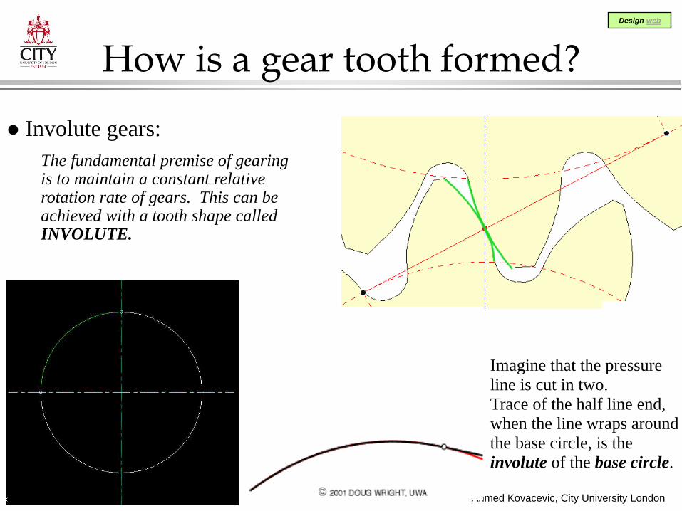
How is a gear tooth formed?
Involute gears:The fundamental premise of gearing is to maintain a constant relative rotation rate of gears. This can be achieved with a tooth shape called INVOLUTE.
Imagine that the pressure line is cut in two. Trace of the half line end, when the line wraps around the base circle, is the involute of the base circle.

Ahmed Kovacevic, City University London
Design web
7
Gear Parameters

Ahmed Kovacevic, City University London
Design web
8
Relations between gear parameters
Gear ratio:
2 2
;30 30
ow G G P P
G G G GP PG P
P P G P
G G P P
P T T TD D N TD nv GR
D N n T
n n
ω ω ω
ω ω
π πω ω
= = =
= = = = = == =
Diametrical pitch
Circular pitch
DiameterModule=
No. of Teeth[ ]
G P
G P
N NPD D
p mPDm mmN
π π
= =
= =
=

Ahmed Kovacevic, City University London
Design web
9 Standard modules are 0.5, 0.8, 1, 1.25, 1.5, 2, 2.5, 3, 4, 5, 6
Module and Pitch
No. of TeethDiametrical pitch = [in-1]
Diameter
DiameterModule = [mm]
No. of Teeth
1 ; [ ]
25.4
N DP m mmD in N
mP
= =
=m=6.35
m=2.11
m=0.97

Ahmed Kovacevic, City University London
Design web
10
Quiz: gear parameters
Pitchdiameter No of teeth Diametral pitch
[in-1]Module[mm]
6” (152.4 mm) 72
90 mm (3.54”) 30
12 3
125 (4.92”) 1.25
12 ~ 2
100
36 ~ 8
~ 8 3
~ 20

Ahmed Kovacevic, City University London
Design web
11
Relations between gear parameters
Centre distance:
Pressure angle: 20o (14.5o)
Addendum: = moduleDedendum: = 1.25 moduleClearance: = 0.25 module
Backlash: clearance measured on the pitch circle of a driving gear
Backlash is functionof module and centre distance
2P GD DC +
=

Ahmed Kovacevic, City University London
Design web
12
Gear forming – rack generation
Rack is the gear with infinite radius.
A rack meshes with a gear in the same way as any other gears mesh.
A Gear can be formed by a rack cutter commencing two movements:» Reciprocating» Translating
All gears with the same module are produced by the same rack cutter

Ahmed Kovacevic, City University London
Design web
13

Ahmed Kovacevic, City University London
Design web
14

Ahmed Kovacevic, City University London
Design web
15

Ahmed Kovacevic, City University London
Design web
16
Gear Force Calculation
Stress based on the Force acting The force is caused by the
transmitted torque. That force always acts along the pressure line.
The force induces stress concentration on gear.
We need to answer: How much power a pair of gears in question can transfer?
Ft
FFr
R
α
30 [ ]
30cos cos
t t
t
PPT F R F Nn R
PFF Fn R
ω π
α π α
= = → =
= → =

Ahmed Kovacevic, City University London
Design web
17
Basic gear stress calculation
Basic analysis of gear-tooth is based on Lewis Equation which has following assumptions:» The full load is applied on the tip of a
single tooth (the worse case)» Radial component is negligible» The load is distributed uniformly
along the teeth width» Friction forces are negligible» Stress concentration is negligible.
Basic stress in teeth
Power transmitted
tB
yB
s
FmbYS
P n D mbYf
σ =
=

Ahmed Kovacevic, City University London
Design web
18
Correction factors
Basic stress must be corrected for:- Shocks,- Size effects,- Uneven load distribution,- Dynamic effects.
a s mB
v
a s mB
v
K K KK
K K KP PK
σ σ=
=
Ka – Application factorKs – Size factorKm – Load distribution factorKv - Dynamic factor

Ahmed Kovacevic, City University London
Design web
19
Gear materials

Ahmed Kovacevic, City University London
Design web
20
Gear wear

Ahmed Kovacevic, City University London
Design web
21
Example
Pinion A and gear B are shown in figure. Pinion A rotates at 1750 rpm, driven directly by an electric motor. The driven machine is an industrial saw consuming 20 kW. The following conditions are given:NP=20 m=3 mm Qv=6NG=70 b=38 mm fs=1.5np=1750 rpm Pow=20 kWWhat is the centre distance? Compute the stress due to bending in the pinion and gear and find required Brinell hardness for this application.
SOLUTION:
Centre distance:
The pitch diameter of the pinion is: [ ]3 20 60[ ] 0.06P PD mN mm m= = ⋅ = =
The pitch velocity is: [ ]P PP
n D 1750 0.06v 5.5[m / s] 1090 ft / min60 60
π π⋅ ⋅= = = =
Transferred load (Tangential force): [ ]60 60 20000 36381750 0.060t
P P
PowF Nn Dπ π
⋅= = =
⋅ ⋅
[ ]( ) ( ) 903 1352 2 2P G P GD D N Nc m mm+ += = = =

Ahmed Kovacevic, City University London
Design web
22
Example – cont.
[ ]
[ ]
6
6
3638 94 100.003 0.038 0.34
3638 76 100.003 0.038 0.42
tBP
P
tBG
G
F PambY
F PambY
σ
σ
= = = ⋅⋅ ⋅
= = = ⋅⋅ ⋅
Basic bending stress is: pinion –
gear -
[ ]62.64 94 10 248a s mP BP
v
K K K MPaK
σ σ= = ⋅ ⋅ =
Correction factors are: Application factor Ka=1.5(from diagrams and tables) Size factor Ks=1.0
Load distribution Km=1.2Dynamic factor Kv=0.68
Corrected pinion bending stress:
[ ]248 1.5 372s PS f MPaσ= = ⋅ =Allowable stress required for
this application:
From the diagram, any material with Brinel hardness higher than HB=400 will satisfy application requirements.
From the diagram: YP=0.34 and YG=0.42