Ahmed Kovacevic, City University London Design web ...ra600/ME1105/HANDOUTS/ME1110-06-H.pdf ·...
13
Ahmed Kovacevic, City University London Design web 1 Representation of features Geometric tolerances Prof Ahmed Kovacevic School of Engineering and Mathematical Sciences Room C130, Phone: 8780, E-Mail: [email protected] www.staff.city.ac.uk/~ra600/intro.htm Engineering Drawing and Design - Lecture 6 ME 1110 – Engineering Practice 1 Ahmed Kovacevic, City University London Design web 2 Objectives for today • How to represent standard engineering features – Gears; Bearings; Seals; Springs – Shafts, tubes; Fasteners • What are tolerances and how are they specified • Geometric tolerances • Surface finish & machining Ahmed Kovacevic, City University London Design web 3 Exercise DrE-5 - Week 7 Parts to be measured and drawn
Transcript of Ahmed Kovacevic, City University London Design web ...ra600/ME1105/HANDOUTS/ME1110-06-H.pdf ·...

Ahmed Kovacevic, City University London
Design web
1
Representation of featuresGeometric tolerances
Prof Ahmed Kovacevic
School of Engineering and Mathematical SciencesRoom C130, Phone: 8780, E-Mail: [email protected]
www.staff.city.ac.uk/~ra600/intro.htm
Engineering Drawing and Design - Lecture 6
ME 1110 – Engineering Practice 1
Ahmed Kovacevic, City University London
Design web
2
Objectives for today
• How to represent standard engineering features
– Gears; Bearings; Seals; Springs– Shafts, tubes; Fasteners
• What are tolerances and how are they specified
• Geometric tolerances
• Surface finish & machining
Ahmed Kovacevic, City University London
Design web
3
Exercise DrE-5 - Week 7
Parts to be measured and drawn

Ahmed Kovacevic, City University London
Design web
4
Representing standard features
Ahmed Kovacevic, City University London
Design web
5
Gears
Ahmed Kovacevic, City University London
Design web
6
Terminology
and
representation
of
standard
components

Ahmed Kovacevic, City University London
Design web
7
Terminology
and
representation
of
standard
components
Ahmed Kovacevic, City University London
Design web
8
Terminology
and
representation
of
standard
components
Ahmed Kovacevic, City University London
Design web
9
Terminology
and
representation
of
standard
components

Ahmed Kovacevic, City University London
Design web
10
Terminology
and
representation
of
standard
components
Ahmed Kovacevic, City University London
Design web
11
Terminology
and
representation
of
standard
components
Ahmed Kovacevic, City University London
Design web
12
Terminology
and
representation
of
standard
components

Ahmed Kovacevic, City University London
Design web
13
Terminology
and
representation
of
standard components
Ahmed Kovacevic, City University London
Design web
14
Terminology
and
representation
of
standard components
Ahmed Kovacevic, City University London
Design web
15
Terminology
and
representation
of
standard
components

Ahmed Kovacevic, City University London
Design web
16
Terminology
and
representation
of
standard
components
Ahmed Kovacevic, City University London
Design web
17
Terminology
and
representation
of
standard
components
Ahmed Kovacevic, City University London
Design web
18
Terminology
and
representation
of
standard
components

Ahmed Kovacevic, City University London
Design web
19
BS 8888 for features and components
� Representation of features
� BS EN ISO 6411 Technical drawings – Simplified repre sentation of centre holes� BS EN ISO 6413 Technical drawings – Representation o f splines and serrations� BS EN ISO 15785 Technical drawings – Symbolic presen tation and indication of adhesive, fold and pressed joints� BS EN 22553 Welded, brazed and soldered joints – Sym bolic representation on drawings� NOTE The BS ISO 128 series of standards covers the general subject of feature representation.
� Representation of components
� BS EN ISO 2162-1 Technical product documentation – Sp rings – Part 1: Simplified representation� BS EN ISO 2162-2 Technical product documentation – Sp rings – Part 2: Data for cylindrical helical compres sion springs� BS EN ISO 2162-3 Technical product documentation – Sp rings –
� BS EN ISO 2203 Technical drawings – Conventional rep resentation of gears
� BS EN ISO 5845-1 Technical drawings – Simplified rep resentation of the assembly of parts with fasteners – Part 1: General principles
� BS EN ISO 6410-1 Technical drawings – Screw threads and threaded parts – Part 1: General conventions� BS EN ISO 6410-2 Technical drawings – Screw threads and threaded parts – Part 2: Screw thread inserts� BS EN ISO 6410-3 Technical drawings – Screw threads and threaded parts – Part 3: Simplified representati on
� BS EN ISO 8826-1 Technical drawings – Roller bearing s – Part 1: General simplified representation� BS EN ISO 8826-2 Technical drawings – Roller bearing s – Part 2: Detailed simplified representation
� BS EN ISO 9222-1 Technical drawings – Seals for dyna mic application – Part 1: General simplified represe ntation� BS EN ISO 9222-2 Technical drawings – Seals for dyna mic application – Part 2: Detailed simplified repres entation
Ahmed Kovacevic, City University London
Design web
20
Tolerances
• Definition:» A tolerance is the total permissible variation of a size,
or the difference between the maximum and minimum limits of size.
• Why is tolerancing necessary?» It is impossible to manufacture a part to an exact size
or geometry» Since variation from the drawing is inevitable the
acceptable degree of variation must be specified» Large variation may affect the functionality of the part» Small variation will effect the cost of the part
� requires precise manufacturing � requires inspection and the rejection of parts
Ahmed Kovacevic, City University London
Design web
21
Example detailed drawing

Ahmed Kovacevic, City University London
Design web
22
Tolerance Declaration
Tolerance can be expressed in different ways:1. Direct tolerancing method (size)
» Limits specifying the allowed variation in each dimension (length, width, height, diameter, etc.) are given on the drawing
2. General tolerance note» Notes like “ALL DIMENSIONS HELD TO �0.05”
3. Geometrical tolerancing» Allows for specification of tolerance for the geometry of a part
separate from its size» GDT (Geometric Dimensioning and Tolerancing) uses special
symbols to control different geometric features of a part
Ahmed Kovacevic, City University London
Design web
23
Datums– Plane surface or axis– Designated in order that some other feature(s) may relate to it– Datums are drawn as shown in the picture
Ahmed Kovacevic, City University London
Design web
24
Geometrical Tolerances
– Geometric tolerance of a feature (point, line, axis, surface) specifies the tolerance zone in which the feature is required to contain.

Ahmed Kovacevic, City University London
Design web
25
NotationSupplementary symbols
Tolerance frame variations
Ahmed Kovacevic, City University London
Design web
26
Tolerance examples
Flatness
Straightness
Ahmed Kovacevic, City University London
Design web
27
Tolerance examples
Roundness
Form
Ahmed Kovacevic, City University London
Design web
28
Tolerance examples
AngularitySymmetry
Ahmed Kovacevic, City University London
Design web
29
Tolerance examples
Parallelism
Squareness
Ahmed Kovacevic, City University London
Design web
30
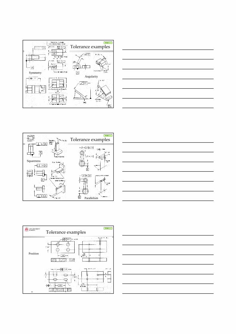
Tolerance examples
Position

Ahmed Kovacevic, City University London
Design web
31
Tolerance examples
Position
Ahmed Kovacevic, City University London
Design web
32
Tolerance examples
Concentricity
Ahmed Kovacevic, City University London
Design web
33
Tolerance examplesCilindricity
Maximum material condition
Profile tolerance

Ahmed Kovacevic, City University London
Design web
34
Surface Roughness
� Average deviation about the mean line measured
� Surface Roughness Measured by value
a O
A
1
A2
A3 An
Mean Line
L
+Y
-Y
RA
La
o
n
=∑
Ahmed Kovacevic, City University London
Design web
35
Surface texture quality
(µµµµm) 0.025 0.05 0.1 0.2 0.4 0.8 1.6 3.2 6.3 12.5 25 50 (µµµµinch) 1 2 4 8 16 32 63 125 250 500 1000 2000 N-Grade N1 N2 N3 N4 N5 N6 N7 N8 N9 N10 N11 N12
Finish Ground Finishes Smooth Turned Medium Turned Rough Machined
Ahmed Kovacevic, City University London
Design web
36
Manufacture methods and
roughness values

Ahmed Kovacevic, City University London
Design web
37
Conclusions
Today we reviewed:� Representation of features and parts� Importance of tolerance� Geometric tolerances
� Surface finish and machining
� To be continued … (next week)