NVH robust optimization of gear macro and microgeometries ...

Measurement of Gear Noise Behaviour for Different Microgeometries
Thanak UTAKAPAN1; Bernhard KOHN2; Max FROMBERGER3; Michael HEIDER4;Michael OTTO5; Bernd-Robert HÖHN6; Karsten STAHL7
1−3,5−7Gears Research Centre (FZG)Technical University of Munich, Germany
4RENK Aktiengesellschaft Augsburg, Germany
ABSTRACTDesigning machines under consideration of noise emission is more than a convenience aspect. For manyapplications, it is rather a major design goal. This is especially true for gear meshes, which are an importantsource of vibration in the transmissions. There are many publications available concerning theoretical aspectsof design of micro geometry of gears for vibration reduction. However, an experimental validation and soundcomparisons among different theoretical designs can be rarely found.Therefore, some basic gear micro geometry designs have been carried out for noise reduction. Special atten-tion has been paid in order to preserve the identical main geometry. This provides an excellent basis for avalid comparison of the influences of a theoretically silent design versus standard design. Since spur gears ex-hibit an inauspicious noise behaviour, measurements have been conducted on this gear type with unmodifiedmicro geometry versus low noise micro geometry. The acceleration measurement results show the advantageof an adequate micro geometry design. As next step, the behaviour of further geometries may be evaluatedin comparison to the results shown in this paper.
Keywords: Gear, Noise, Micro Geometry I-INCE Classification of Subjects Numbers:11.1.3, 72.9, 74.8
1. INTRODUCTIONBesides the load carrying capacity, NVH is one of the most important considerations for gearboxes. Ex-
citation induced by gear meshes can be transmitted throughout the gearbox in the form of structure-bornenoise. This can finally be transferred into airborne noise on housing surfaces. Under many circumstances,this noise is found to be disturbing and can affect the product quality.
Over the past few decades, many researchers have dedicated themselves to reduce noise excitation in gearmeshes. One of the most promising solutions is the modification on the tooth micro geometry. In theory, itcan be shown that lower excitation of gear meshes can be archived by means of flank modifications. However,documented experimental validations can be rarely found.
In this paper, experimental validations of the influence of micro geometries on gear mesh excitation shallbe presented. The experiments were conducted mainly on spur gears, as they are well-known for their un-favourable noise behaviour. In comparison with helical gears with identical macro geometries, spur gearstend to be a lot more sensitive to the gear mesh excitation due to their discrete leaps between double andsingle engagements along the line of contact. However, spur gears are sometimes more favourable especiallyunder constructional restrictions, where helical gears may be disadvantageous, i.e. by means of designing thebearings. In many cases, the absence of the axial force in spur gears can reduce further constructional com-plexities as well as manufacturing cost. Thus, the design of quiet spur gears is practically the compromisingsolution.
[email protected]@[email protected]@[email protected]@fzg.mw.tum.de
INTER-NOISE 2016
3964
2. THEORETICAL FUNDAMENTALSThe noise behaviour of gearboxes is fundamentally dominated by the excitation in the gear meshes them-
selves. This excitation is actually the resulting phenomenon, in which many effects participate. These effectshave been thoroughly examined by several researchers over the last few decades (see also (1–8)).
Some significant effects can be exemplary mentioned here. The variable mesh stiffness within each en-gagement defines the relationship between the load and the corresponding mesh deformation. The meshstiffness itself is a result of the specific tooth pairing stiffnesses. This mesh stiffness can be varied by differ-ent gear contact ratios (transverse as well as overlap). Furthermore, the contact ratios can be extended underthe loaded condition by means of premature and prolonged engagements, which induces another significanteffect for the mesh excitation (see also (9)). The deformation of shafts also affects the mesh excitation and isthe result of the interaction among shafts and bearings. Other effects are the directional transition of frictionat the pitch point, the asperities of gear wheels, etc.
In addition to the foregoing, the form deviation of gear meshes from their actual involute profile is abso-lutely one of the non-negligible causes for the mesh excitation. The form deviation consists of manufacturingtolerances as well as modifications, which are specifically applied to the meshes for optimizing purposes likewidth load distribution, efficiency, and definitely, noise behaviour.
In a stationary state, the deformation of gear mesh x at a specific mesh point, which can be expressed interm of time t, due to the load F can be calculated under consideration of form deviation x f i at each contactpoint as:
x(t) =F −∑
ici(t) · x f i(t)
∑i
c(t)(1)
This deformation is also known as the loaded transmission error (LTE). The loaded transmission errorcharacterizes mesh excitation and therefore can be used as prediction value for noise behaviour as stated in(10). Some further examinations can also be found in (11, 12). In order to improve noise behaviour of gears,the progress of the loaded transmission error over teeth engagements needs to be kept as constant as possible(see also (13–15)). That is, fluctuations of the LTE should be minimized.
Invo
lute
diag
ram
Mes
hSt
iffne
ss
Mod
ifica
tion
Am
ount
A EB D
Modification Length
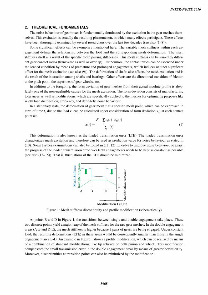
Figure 1: Mesh stiffness discontinuity and profile modification (schematically)
At points B and D in Figure 1, the transitions between single and double engagement take place. Thesetwo discrete points yield a major leap of the mesh stiffness for the raw gear meshes. In the double engagementareas (A-B and D-E), the mesh stiffness is higher because 2 pairs of gears are being engaged. Under constantload, the resulting deformations (LTE) in these areas would be consequently smaller than those in the singleengagement area B-D. An example in Figure 1 shows a profile modification, which can be realized by meansof a combination of standard modifications, like tip relieves on both pinion and wheel. This modificationcompensates the small transmission error in the double engagement areas by means of greater deviation x f .Moreover, discontinuities at transition points can also be minimized by the modification.
INTER-NOISE 2016
3965

3. EXPERIMENTAL SETUP3.1 FZG Dynamic Test Rig
The experiments were performed on the FZG dynamic test rig with standard centre distance of 140 mm,which is depicted schematically in Figure 2. The test rig makes use of the mechanical power circulationprinciple, which is commonly utilized in FZG back-to-back test rigs. The test rig consists of two sets ofgearboxes, the test gearbox and the drive gearbox. These gearboxes are connected together by two shafts.The loading clutch was installed on one of these shafts, deviding this shaft into two parts.
main drive
auxiliary drivedrive gearbox
loading clutchtest gearbox
Figure 2: FZG dynamic test rig
In order to bring static load into the test rig, the loading clutch shall be decoupled. One of the clutchedshafts must then be elastically twisted by means of a lever with adjusted weight. Under this circumstance,engaging the loading clutch shall provide a constant static load torque to the test rig during the test operation,so that high tension can be archived in the system independently from the drive aggregate, which mainlyprovides speed and some sufficient load, which may lose during the operation due to the efficiency.
The FZG dynamic test rig is equipped with two drive aggregates, in order to cover a wide range ofoperational speed. The main drive provides high speed range for dynamic measurements, while this can thenbe decoupled in the slow speed operation, during which the auxiliary drive is used. Loaded transmission erroris a good example of a measurable value in the slow speed operation.
3.2 MeasurementsIn order to acquire a complete information about the noise behaviour of gears, two measurements need to
be carried out for each variation. These are:
• measurement of loaded transmission error
• measurement of torsional acceleration
With the measurement of loaded transmission error, the quasi-static excitation of gear meshes can beidentified. On the other hand, the measurement of torsional acceleration would retrieve the dynamic charac-teristics of the gear meshes over a broad range of speed.
Moreover, the gear meshes were applied with 6 load stages described in Table 1 in favour of a goodoverview of the noise behaviour of gears over different loads.
Measurement of Loaded Transmission ErrorThe objective of the measurement is to identify the intrinsic excitation of the gear meshes under a specific
external load. Therefore, a low rotational speed is required. Distortions due to accelerational effects can thenbe neglected. The measurements were performed at the speed of the pinion at 5 rpm. The angular positionsof the pinion and the wheel are recorded by means of high resolution Heidenhain incremental encoders. Thisdigital sensor detects the position of the gear thanks to its optical transmitter and receiver.
The measured loaded transmission error can be defined as:
x = ϕ1 · rb1 −ϕ2 · rb2 (2)
INTER-NOISE 2016
3966

Table 1: Load stages for the experiments
Load Stage Load on PinionNm
1 4002 6663 10004 13345 16006 2000
, whereas rb1 and rb2 are base diameters of pinion and wheel respectively. According to Equation 2, therewould be no transmission error, if the gear ratio is ideal (ϕ1 = i12 ·ϕ2). An ideal involute profile gear meshwith no external load would satisfy this condition. The transmission error can also be defined by means of anangular expression as follows:
∆ϕ = i12 ·ϕ1 −ϕ2 (3)
Measurement of Torsional Acceleration
2
3
1
+
ϕx
Figure 3: measuring disc with sensors
The measurement of torsional acceleration enables the de-tection of the actual excitation within the meshing under thedynamic situation. The torsional acceleration can be measuredon either wheel. However, the sensors should be placed directlyunder the gear wheel, so that no further transmission path candistort the measurement.
For this measurement, three acceleration sensors were at-tached in the gear wheel in both radial and tangential direc-tions. By combining these measured values mathematically,torsional as well as bending acceleration can then be identi-fied. For instance, the torsional acceleration can be identifiedby the addition of the radial and tangential sensors depicted inFigure 3.
For this measurement, the speed of the pinion varied be-tween n = 400 rpm to n = 5300 rpm with speed step at ∆n = 20 rpm. During the measurement, the speed ofthe pinion was held constant, yielding a quasi-run-up measurement.
3.3 Experimental VariationsThe experiments were carried out on two different toothings. The data of their macro geometries are
shown in Table 2. Both toothings differ solely from their usable tip diameters.
Table 2: Macro geometries of tested gear sets
Unit Normal Toothing High ToothingPinion Wheel Pinion Wheel
number of teeth z1/z2 - 43 45 43 45centre distance a mm 140 140normal module mn mm 3.21 3.21profile shift x1/x2 - -0.1747 -0.1984 -0.1747 -0.1984width b1/b2 mm 39.5 39.5 39.5 39.5root diameter dF,1/dF,2 mm 127.604 133.874 127.604 133.874usable tip diameter dNa,1/dNa,2 mm 142.5 148 144.2 150.5transverse contact ratio εα,N mm 1.5 2.0
INTER-NOISE 2016
3967
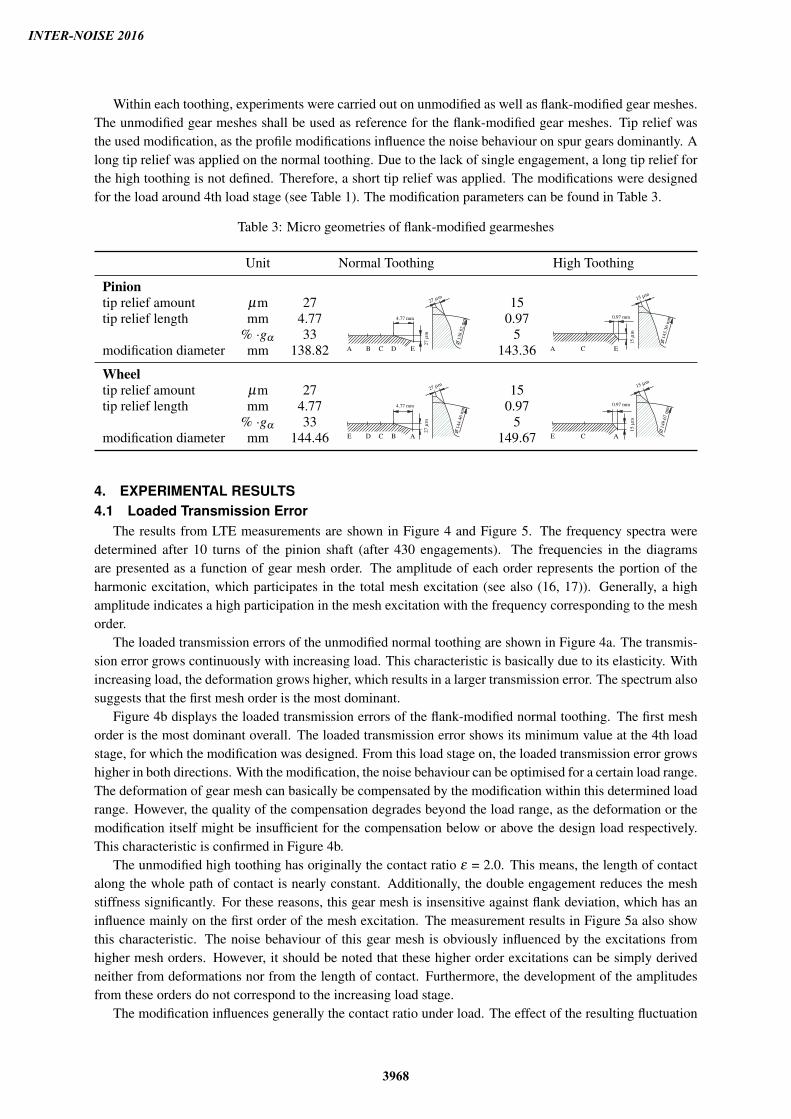
Within each toothing, experiments were carried out on unmodified as well as flank-modified gear meshes.The unmodified gear meshes shall be used as reference for the flank-modified gear meshes. Tip relief wasthe used modification, as the profile modifications influence the noise behaviour on spur gears dominantly. Along tip relief was applied on the normal toothing. Due to the lack of single engagement, a long tip relief forthe high toothing is not defined. Therefore, a short tip relief was applied. The modifications were designedfor the load around 4th load stage (see Table 1). The modification parameters can be found in Table 3.
Table 3: Micro geometries of flank-modified gearmeshes
Unit Normal Toothing High Toothing
Piniontip relief amount µm 27
A B C D E
4.77 mm
27µ
m
27 µm
�13
8.82
mm
15
A C E
0.97 mm
15µ
m
15 µm
�14
3.36
mmtip relief length mm 4.77 0.97
% ·gα 33 5modification diameter mm 138.82 143.36
Wheeltip relief amount µm 27
E D C B A
4.77 mm
27µ
m
27 µm
�14
4.46
mm
15
E C A
0.97 mm
15µ
m
15 µm
�14
9.67
mmtip relief length mm 4.77 0.97
% ·gα 33 5modification diameter mm 144.46 149.67
4. EXPERIMENTAL RESULTS4.1 Loaded Transmission Error
The results from LTE measurements are shown in Figure 4 and Figure 5. The frequency spectra weredetermined after 10 turns of the pinion shaft (after 430 engagements). The frequencies in the diagramsare presented as a function of gear mesh order. The amplitude of each order represents the portion of theharmonic excitation, which participates in the total mesh excitation (see also (16, 17)). Generally, a highamplitude indicates a high participation in the mesh excitation with the frequency corresponding to the meshorder.
The loaded transmission errors of the unmodified normal toothing are shown in Figure 4a. The transmis-sion error grows continuously with increasing load. This characteristic is basically due to its elasticity. Withincreasing load, the deformation grows higher, which results in a larger transmission error. The spectrum alsosuggests that the first mesh order is the most dominant.
Figure 4b displays the loaded transmission errors of the flank-modified normal toothing. The first meshorder is the most dominant overall. The loaded transmission error shows its minimum value at the 4th loadstage, for which the modification was designed. From this load stage on, the loaded transmission error growshigher in both directions. With the modification, the noise behaviour can be optimised for a certain load range.The deformation of gear mesh can basically be compensated by the modification within this determined loadrange. However, the quality of the compensation degrades beyond the load range, as the deformation or themodification itself might be insufficient for the compensation below or above the design load respectively.This characteristic is confirmed in Figure 4b.
The unmodified high toothing has originally the contact ratio ε = 2.0. This means, the length of contactalong the whole path of contact is nearly constant. Additionally, the double engagement reduces the meshstiffness significantly. For these reasons, this gear mesh is insensitive against flank deviation, which has aninfluence mainly on the first order of the mesh excitation. The measurement results in Figure 5a also showthis characteristic. The noise behaviour of this gear mesh is obviously influenced by the excitations fromhigher mesh orders. However, it should be noted that these higher order excitations can be simply derivedneither from deformations nor from the length of contact. Furthermore, the development of the amplitudesfrom these orders do not correspond to the increasing load stage.
The modification influences generally the contact ratio under load. The effect of the resulting fluctuation
INTER-NOISE 2016
3968

Am
plitu
deof
Loa
ded
Tran
smis
sion
Err
or/µ
m
Am
plitu
deof
Loa
ded
Tran
smis
sion
Err
or/a
ngul
arse
cond
0
3.14
6.29
0
10
20
0
3.14
6.29
0
10
20
0
3.14
6.29
0
10
20
0
3.14
6.29
0
10
20
0
3.14
6.29
0
10
20
0
3.14
6.29
0
10
20
1 2 3 4Gear mesh order / -
T = 400 Nm
T = 666 Nm
T = 1000 Nm
T = 1334 Nm
T = 1600 Nm
T = 2000 Nm
Am
plitu
deof
Loa
ded
Tran
smis
sion
Err
or/µ
m
Am
plitu
deof
Loa
ded
Tran
smis
sion
Err
or/a
ngul
arse
cond
0
3.14
6.29
0
10
20
0
3.14
6.29
0
10
20
0
3.14
6.29
0
10
20
0
3.14
6.29
0
10
20
0
3.14
6.29
0
10
20
0
3.14
6.29
0
10
20
1 2 3 4Gear mesh order / -
T = 400 Nm
T = 666 Nm
T = 1000 Nm
T = 1334 Nm
T = 1600 Nm
T = 2000 Nm
(a) Unmodified gear mesh (b) Flank-modified gear mesh
Figure 4: Spectra of loaded transmission errors from gear meshes with normal toothing
INTER-NOISE 2016
3969

Am
plitu
deof
Loa
ded
Tran
smis
sion
Err
or/µ
m
Am
plitu
deof
Loa
ded
Tran
smis
sion
Err
or/a
ngul
arse
cond
0
3.14
6.29
0
10
20
0
3.14
6.29
0
10
20
0
3.14
6.29
0
10
20
0
3.14
6.29
0
10
20
0
3.14
6.29
0
10
20
0
3.14
6.29
0
10
20
1 2 3 4Gear mesh order / -
T = 400 Nm
T = 666 Nm
T = 1000 Nm
T = 1334 Nm
T = 1600 Nm
T = 2000 Nm
Am
plitu
deof
Loa
ded
Tran
smis
sion
Err
or/µ
m
Am
plitu
deof
Loa
ded
Tran
smis
sion
Err
or/a
ngul
arse
cond
0
3.14
6.29
0
10
20
0
3.14
6.29
0
10
20
0
3.14
6.29
0
10
20
0
3.14
6.29
0
10
20
0
3.14
6.29
0
10
20
0
3.14
6.29
0
10
20
1 2 3 4Gear mesh order / -
T = 400 Nm
T = 666 Nm
T = 1000 Nm
T = 1334 Nm
T = 1600 Nm
T = 2000 Nm
(a) Unmodified gear mesh (b) Flank-modified gear mesh
Figure 5: Spectra of loaded transmission errors from gear meshes with high toothing
INTER-NOISE 2016
3970
of the length of contact can be visualized in the amplitude at the first mesh order. This is also true for theflank modified high toothing, of which the measurement results are presented in Figure 5b. Moreover, themodification tends to reduce the amplitudes at the higher mesh orders. The reason for this phenomenon canbe traced back to the reduction of the premature and the prolonged engagements, which consequently meansthe reduction of impacts along the path of contact.
4.2 Torsional AccelerationThe measurements of the torsional acceleration were carried out over load stages predefined in Section 3.2.
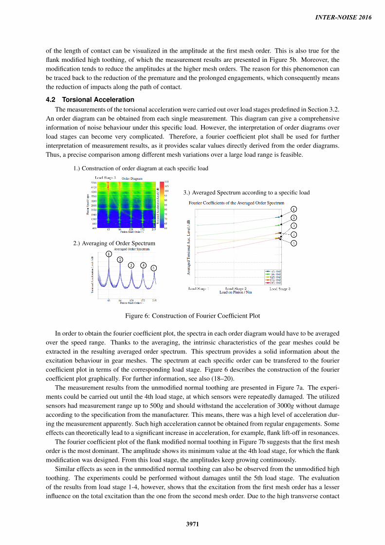
An order diagram can be obtained from each single measurement. This diagram can give a comprehensiveinformation of noise behaviour under this specific load. However, the interpretation of order diagrams overload stages can become very complicated. Therefore, a fourier coefficient plot shall be used for furtherinterpretation of measurement results, as it provides scalar values directly derived from the order diagrams.Thus, a precise comparison among different mesh variations over a large load range is feasible.
1.) Construction of order diagram at each specific load
2.) Averaging of Order Spectrum
3.) Averaged Spectrum according to a specific load
Figure 6: Construction of Fourier Coefficient Plot
In order to obtain the fourier coefficient plot, the spectra in each order diagram would have to be averagedover the speed range. Thanks to the averaging, the intrinsic characteristics of the gear meshes could beextracted in the resulting averaged order spectrum. This spectrum provides a solid information about theexcitation behaviour in gear meshes. The spectrum at each specific order can be transfered to the fouriercoefficient plot in terms of the corresponding load stage. Figure 6 describes the construction of the fouriercoefficient plot graphically. For further information, see also (18–20).
The measurement results from the unmodified normal toothing are presented in Figure 7a. The experi-ments could be carried out until the 4th load stage, at which sensors were repeatedly damaged. The utilizedsensors had measurement range up to 500g and should withstand the acceleration of 3000g without damageaccording to the specification from the manufacturer. This means, there was a high level of acceleration dur-ing the measurement apparently. Such high acceleration cannot be obtained from regular engagements. Someeffects can theoretically lead to a significant increase in acceleration, for example, flank lift-off in resonances.
The fourier coefficient plot of the flank modified normal toothing in Figure 7b suggests that the first meshorder is the most dominant. The amplitude shows its minimum value at the 4th load stage, for which the flankmodification was designed. From this load stage, the amplitudes keep growing continuously.
Similar effects as seen in the unmodified normal toothing can also be observed from the unmodified hightoothing. The experiments could be performed without damages until the 5th load stage. The evaluationof the results from load stage 1-4, however, shows that the excitation from the first mesh order has a lesserinfluence on the total excitation than the one from the second mesh order. Due to the high transverse contact
INTER-NOISE 2016
3971

ratio (ε = 2.0), the characteristic of the stiffness fluctuation in the mesh changes in comparison to the normaltoothing, so that the second mesh order has a major role in the mesh excitation. This phenomenon can alsobe seen in Figure 7c.
With the predefined tip relief, the flank-modified high toothing shows lower acceleration levels than theunmodified variant. As depicted in Figure 7d, the excitation from the first mesh order exhibits a comparablelevel to the one from the second mesh order at lower load stages, and keeps up the same level over the wholeload stages. The amplitude from the second mesh order tends to develop over the increasing load stages.However, the total acceleration levels are lower than those of the unmodified high toothing.
Ave
rage
dTo
rsio
nalA
cc.L
evel
/dB
70
75
80
85
90
95
100
105
110
115
120
400 666 1000Load on Pinion / Nm
215. Ord172. Ord129. Ord86. Ord43. Ord
(a) Unmodified normal toothing
Ave
rage
dTo
rsio
nalA
cc.L
evel
/dB
70
75
80
85
90
95
100
105
110
115
120
400 666 1000 1334 1600 2000Load on Pinion / Nm
215. Ord172. Ord129. Ord86. Ord43. Ord
(b) Flank-modified normal toothing
Ave
rage
dTo
rsio
nalA
cc.L
evel
/dB
70
75
80
85
90
95
100
105
110
115
120
400 666 1000 1334Load on Pinion / Nm
215. Ord172. Ord129. Ord
86. Ord43. Ord
(c) Unmodified high toothing
Ave
rage
dTo
rsio
nalA
cc.L
evel
/dB
70
75
80
85
90
95
100
105
110
115
120
400 666 1000 1334 1600 2000Load on Pinion / Nm
215. Ord172. Ord129. Ord86. Ord43. Ord
(d) Flank-modified high toothing
Figure 7: Fourier Coefficients Plots of the Averaged Order Spectra of different gear meshes
5. SUMMARYIn this paper, the effects of gears micro geometries on noise behaviour were experimentally evaluated. The
experimental results show that, there is a correlation between the loaded transmission error and the torsionalacceleration. Thus, it can be said that, the excitation by means of transmission error under load is a majorcause for the excitation in gear meshes.
The flank modifications can be used generally in order to reduce the excitation in gear meshes. For acommon normal toothing, the optimisation can be done for a specific load range. Overall comparison ofthe four cases shows that the unmodified high toothing provides significantly lower excitation levels thanthe unmodified normal toothing. The modified normal toothing reaches a similar or even lower excitationlevel than the unmodified high toothing for design load only. The modified high toothing provides the lowestexcitation level of the tested meshes over a wide load range.
INTER-NOISE 2016
3972
Adequate care has to be taken in comparing the noise behaviour of normal and high toothing, as differentmesh orders dominate the total excitation. Especially under the subcritical operation, high excitations can beinduced easier by the second mesh order. Under this circumstance, the noise advantage of the high toothingcan therefore be affected by this effect.
REFERENCES1. H. Rettig. Innere dynamische Zusatzkräfte bei Zahnradgetrieben. In Antriebstechnik 16 Nr. 11, S. 655-
663. Frankfurt am Main, 1977.
2. H. Gerber. Innere dynamische Zusatzkräfte bei Stirnradgetrieben. PhD thesis, TU München, 1984.
3. R. Müller. Schwingungs- und Geräuschanregung bei Stirnradgetrieben. PhD thesis, TU München, 1991.
4. K. Sattelberger. Schwingungs- und Geräuschanregung bei ein- und mehrstufigen Stirnradgetrieben. PhDthesis, TU München, 1997.
5. H. Geiser. Grundlagen zur Beurteilung des Schwingungsverhaltens von Stirnrädern. PhD thesis, TUMünchen, 2002.
6. S. Radev. Einfluss von Flankenkorrekturen auf das Anregungsverhalten gerad - und schrägverzahnterStirnradpaarungen. PhD thesis, TU München, 2007.
7. T. Griggel. Einfluss von Korrekturen und Fertigungsabweichungen auf die Schwingungsanregung vonStirnrädern. PhD thesis, TU München, 2010.
8. M. Heider. Schwingungsverhalten von Zahnradgetrieben - Beurteilung und Optimierung desSchwingungsverhaltens von Stirnrad- und Planetengetrieben. PhD thesis, TU München, 2012.
9. J. Baethge. Drehwegfehler, Zahnfederhärte und Geräusch bei Stirnrädern. PhD thesis, TH München,1969.
10. R. Gregory, S. Harris, and R. Munro. Dynamic behaviour of spur gears. In Proc. Inst. Mech. Eng., Vol.178 Pt I No 8, S. 207-226. Inst. Mech. Eng, 1963-64.
11. A. Kubo and S. Kiyono. Vibrational excitation of cylindrical involute gears due to tooth form error. InBulletin of the JSME, Vol. 23, No. 183, September 1980, pp. 1536 - 1543, 1980.
12. P. Davoli, C. Gorla, Rossa, F F, Rossi, and G. Boni. Transmission error and noise excitation of spurgears. In Proceedings of the ASME 2007 10th ASME International Power Transnmisson and GearingConference, Las Vegas - DETC2007-34099, 2007.
13. S. Harris. Dynamic loads on the teeth of spur gears. In Proc. Inst. Mech. Eng., Vol. 172, S. 87-112. Inst.Mech. Eng, 1958.
14. A. Fuentes, I. Gonzalez-Perez, H. Nagamoto, and K. Hayasaka. Gear whine noise spectra caused bytransmission errors. In Proceedings of the ASME 2011 - 11th ASME International Power Transmissionand Gearing Conference, Washington DC - DETC2011-48126, 2011.
15. R. Munro. Effect of geometrical errors on the transmission of motion between gears. In Proc. Conferenceon Gearing in 1970, Cambridge, pp. 79 - 84, 1970.
16. W. Mark. Analysis of the vibratory excitation of gear systems: Basic theory. In J. Acoust. Soc. Am.63(5), May 1978, pp. 1409 - 1430, 1978.
17. W. Mark. Analysis of the vibratory excitation of gear systems. II: Tooth error representations, approxi-mations, and application. In J. Acoust. Soc. Am. 66(6), Dec 1979, pp. 1758 - 1787, 1979.
INTER-NOISE 2016
3973

18. T. Griggel, M. Heider, A. Gacka, T. Röthlingshöfer, and J. Ingeli. FVA-Heft 936: FVA-Forschungsvorhaben 487 II, Kennwerte Anregungsverhalten, Analyse der BerechnungsprogrammeDZP4, RIKOR H und FE-Stirnradkette 3.1. Abschlussbericht, Forschungsvereinigung Antriebstechnike.V. (FVA), Frankfurt/Main, 2010.
19. M. Heider and J. Ingeli. FVA-Heft 983: FVA-Forschungsvorhaben 487 III, Neue Kennwerte zur rech-nerischen Beurteilung des Anregungsverhaltens von Verzahnungen. Abschlussbericht, Forschungsver-einigung Antriebstechnik e.V. (FVA), Frankfurt/Main, 2011.
20. T. Utakapan. FVA-Heft 1101: FVA-Forschungsvorhaben 487 IV, Neue Kennwerte zur rechnerischenBeurteilung des Anregungsverhaltens von Verzahnungen. Abschlussbericht, ForschungsvereinigungAntriebstechnik e.V. (FVA), Frankfurt/Main, 2015.
INTER-NOISE 2016
3974