GEARS & GEAR DRIVES - Gear Product News
52
GEARS & GEAR DRIVES The Things That Really Move Us THE LATEST PRODUCTS Capstan Atlantic’s Gear Quality Why We Shot Peen Gears Aren’t Machines Supposed to Fail? Keeping the Oil Clean Case Study: Process Equipment at Remy Case Study: United Gear & Assembly Switches to Dry Hobbing April 2005 PRODUCT www.gearproductnews.com
Transcript of GEARS & GEAR DRIVES - Gear Product News
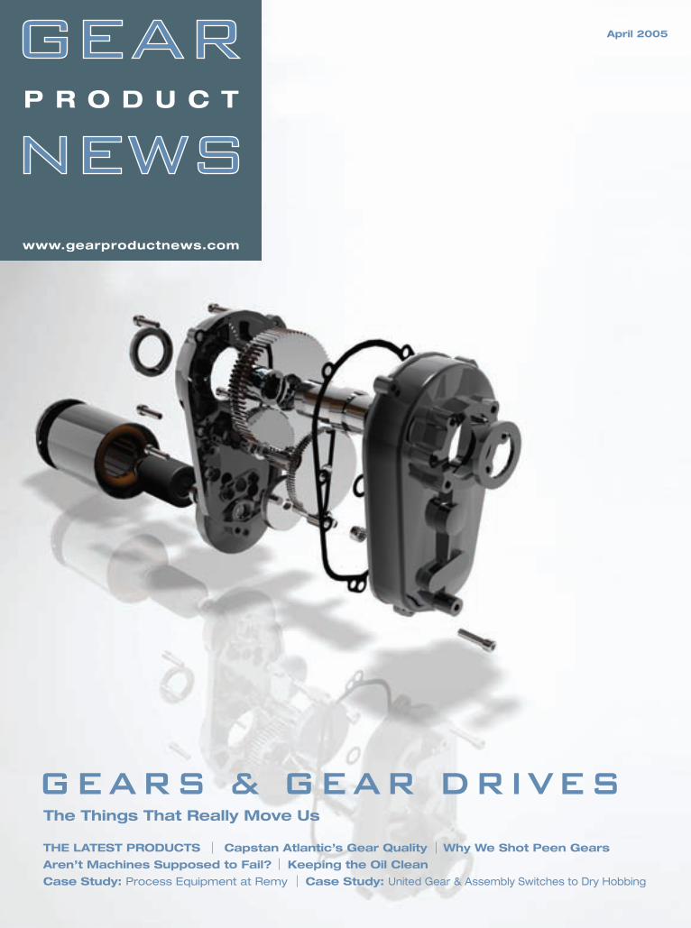
GEARS & GEAR DRIVES The Things That Really Move Us
THE LATEST PRODUCTS Capstan Atlantic’s Gear Quality Why We Shot Peen Gears
Aren’t Machines Supposed to Fail? Keeping the Oil Clean
Case Study: Process Equipment at Remy Case Study: United Gear & Assembly Switches to Dry Hobbing
April 2005
P R O D U C T
www.gearproductnews.com
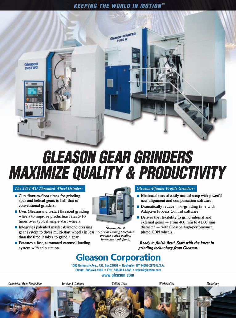
KEEPING THE WORLD IN MOTION ™
Cylindrical Gear Production WorkholdingService & Training MetrologyCutting Tools
1000 University Ave., P.O. Box 22970 • Rochester, NY 14692-2970 U.S.A. Phone: 585/473-1000 • Fax: 585/461-4348 • [email protected]
www.gleason.com
GLEASON GEAR GRINDERSMAXIMIZE QUALITY & PRODUCTIVITY
The 245TWG Threaded Wheel Grinder:
� Cuts floor-to-floor times for grinding spur and helical gears to half that of conventional grinders.
� Uses Gleason multi-start threaded grindingwheels to improve production rates 5-10times over typical single-start wheels.
� Integrates patented master diamond dressinggear system to dress multi-start wheels in lessthan the time it takes to grind a gear.
� Features a fast, automated carousel loading system with spin station.
Gleason-Pfauter Profile Grinders:
� Eliminate hours of costly manual setup with powerfulnew alignment and compensation software.
� Dramatically reduce non-grinding time withAdaptive Process Control software.
� Deliver the flexibility to grind internal and external gears — from 400 mm to 4,000 mmdiameter — with Gleason high-performance plated CBN wheels.
Ready to finish first? Start with the latest in grinding technology from Gleason.
Gleason-Hurth ZH Gear Honing Machines
produce a high quality, low-noise tooth flank.

f e a t u r e s
CAPSTAN ATLANTIC/MODAL SHOP
Sound Waves That Measure Quality
16
INDIANATOOL-
INDIANAGEAR
Why We Shot Peen Gears
20
SHOT PEENINGRESOURCES
References on Gear Shot Peening
22
POWER TRANSMISSIONSign Up for Free Listings in our June
Power Transmission Buyers Guide
24
MACHINERY LUBRICATIONAren’t Machines Supposed to Fail?
30
MAGNOMKeeping the Oil Clean
34Cover photo courtesy of
� � � � � � �
*You can also fill out this form at www.gearproductnews.com.
STEP ONE – Company Information(This is how your information will appear in the buyers guide.)
Company Name:
Street Address:
City: State: ZIP:
Country:
Phone: Fax:
E-mail:
Website: Website:
STEP TWO – Contact Information(This information will NOT appear in the directory. It’s just so we can contact you if there are any questions.)
Name:
Title:
Phone:
Fax:
E-mail:
Signature: � � � � � � � � � � Date: � � �
STEP THREE – OptionsIn conjunction with free listings in our printed directory, we will be offering a number of advertising options, both in the June issue of Gear Product News and on our website, powertransmission.com. There’s no obligation for checking the boxes below, but if you’re interested, we’d like to tell you more about the options!
I am interested in a directory ad (1/8 page in the printed guide, $295). I am interested in other display advertising in Gear Product News. I am interested in extending my listings to powertransmission.com. I am interested in banner advertising on powertransmission.com.
STEP FOUR – Choose Your CategoriesUse the checkboxes on the following four pages to select the categories under which your company should appear in the June 2005 Power Transmission Buyers Guide.
THE GEAR PRODUCT NEWS POWER TRANSMISSION BUYERS GUIDE
RANDALL PUBLISHING, INC. • P.,O. BOX 1426, ELK GROVE VILLAGE, IL 60009 • PH: 847-437-6604
When you’re done,FAX THESE PAGES TO 847-437-6618
THE GEAR PRODUCT NEWS POWER TRANSMISSION BUYERS GUIDE
If y o u s e l lGEARS, BEARINGS, MOTORS, SPEED REDUCERS, CLUTCHES, BRAKES,
COUPLINGS or OTHER POWER TRANSMISSION COMPONENTS, YOU ARE ENTITLED TO
FREE LISTINGS in the 2005 Power Transmission Buyers Guide.*
MORE
���
������ ����������� ��� �������� ��� ����� ����� ����� �������� ������������������������������������������������������������������������� ����������� ��� ��������� ������������������������������������������������������������������������������������������������������������������������������������������������������������������������������������������������������������������������������� ������������ ���� ������������ ��� ��� ���� ������ �������������� ���� ������������ ��� ������� ��� ����� �������� ����� ��������������� ��������������������������������������������������������������������� ���������� ����� ���������������� �������������
�������������������������������������������������������������
���� ����� �������� ���������� �������� ��������� ���� �������������������������������������������������������������������������������������������������������������������������������������������������������������������������������������������������������������������������������������������������������������������� ��������� ����������� ���� ������ ��� ������������� ������������ ��������������� �������������� ���������� ������������ ���
�����������������������������������������To learn more about the shot peening of gears, visit www.shotpeener.com to browse its online library for techni-cal papers like these. More than 100 gear-related shot peening articles are included there, and many of them are downloadable as PDF files.
������ ����������� ��� �������� ��� ����� ����� ����� �������� ������������������������������������������������������������������������� ����������� ��� ��������� ������������������������������������������������������������������������������������������������������������������������������������������������������������������������������������������������������������������������������� ������������ ���� ������������ ��� ��� ���� ������ �������������� ���� ������������ ��� ������� ��� ����� �������� ����� ��������������� ��������������������������������������������������������������������� ���������� ����� ���������������� �������������
������ ��������������� �������������� ���������� ������������ ���
������������www.shotpeener.com
cal papers like these. More than 100 gear-related shot peening articles are included there, and many of them are

Gear Product News April 2005 Gear Product News April 2005 Gear Product News April 2005 2 Gear Product News April 2005 Gear Product News April 2005 Gear Product News April 2005 Gear Product News April 2005
d e p a r t m e n t s
product news Focus on Gears and
Gear Drives
5
Case StudyProcess Equipment Helps
Remy Streamline Inspection
40
Case StudyUnited Gear & AssemblySwitches to Dry Hobbing
42
industry newsThe Latest Gear Newsfrom Around the World
44
subscriptions Fill Out the Form to Continue Receiving
Gear Product News
46
classified Our Product & Service Marketplace
47
advertiser index Contact Information for Gear Industry
Suppliers
48
Editorial
Publisher & Editor-in-ChiefMichael Goldstein
Managing EditorWilliam R. Stott
Associate EditorJoseph L. Hazelton
Assistant EditorRobin Wright
Art
Graphic DesignerKathleen O’Hara
Advertising
Business Development ManagerDaniel Pels
powertransmission.com SalesClark Hopkins
Internet
Web DeveloperDan MacKenzie
Contacts
Randall Publishing, Inc.P.O. Box 1426
1425 Lunt Ave.Elk Grove Village, IL 60007
Phone: (847) 437-6604Fax: (847) 437-6618
E-mail: [email protected]
� � � � � � �
GEAR TECHNOLOGYThe Journal of Gear Manufacturing
Fax
your
form
to (8
47) 4
37-6
618
or v
isit
us a
t ww
w.g
earp
rodu
ctne
ws.
com
or w
ww
.gea
rtec
hnol
ogy.
com
1. What is the principal product manufactured or service performed at THIS LOCATION?_______________________________________________________
2. How is THIS LOCATION involved in the gear industry? (Check all that apply) WE MAKE GEARS AND SELL THEM-Gear Job Shop (20,3) WE MAKE GEARS AND USE THEM IN OUR PRODUCTS-Captive Gear Shop (20,2) WE BUY GEARS (22)
IN ORDER TO QUALIFY FOR (OR RENEW) A FREE SUBSCRIPTION, YOU MUST ANSWER ALL THE QUESTIONS BELOW.
Name:_______________________________________________________ Title:__________________________________________________________
Company Name:_______________________________________________ E-mail:__________________________________________________________
Company Address:_____________________________________________ Parent Co. Name: ________________________________________________
City:_________________________________________________________ State:________________________________ ZIP:______________________
Telephone:______________________________ Fax:__________________ Internet Address:_______________________________________________
____YES, I would like to receive Gear Product News ____ NO Signature_____________________________________ Title_________________________
I would like to receive the ____ print version ____ electronic E-GPN ____ both (need e-mail address)___________________________________
THERE’S ONLY ONE WAY...to learn about the products, companies and people of the gear industry.To learn about our technical field without all the technical depth...Sign uptoday to receive your FREE subscription to Gear Product News magazine.It's the perfect complement to Gear Technology.
GPNGT
� � � � � � �
�����������������������
THERE’S ONLY ONE WAY...to have the most in-depth information available on gear design, manufacturing, processing, buying and use...Sign up today to receive your FREE subscription to Gear Technology magazine. Our flagship publication in print for 20 years.
____YES, I would like to receive Gear Technology Technology Technology ____ NO Signature_____________________________________ Title_________________________
I would like to receive the ____ print version ____ electronic E-GT ____ both (need e-mail address)_____________________________________
�
SEND YOUR COMPLETE SUBSCRIPTION FORM TO
P.O. BOX 1426, ELK GROVE VILLAGE, IL 60007 OR FAX TO (847) 437-6618
Fax
your
form
to (8
47) 4
37-6
618
or v
isit
us a
t
WE BUY GEARS (22)

KAPP ) nilesKAPP Technologies 2870 Wilderness Place Boulder, CO 80301
Ph: 303-447-1130 Fx: 303-447-1131
www.kapp-usa.com [email protected]
The KAPP KX300P is a small-footprint
machine with huge capabilities. It features
two grinding processes, two tool concepts,
on-board balancing, and on-board gear
inspection. It uses both dressable vitrified
tools and CBN tools. The KX300P has a
vertical workpiece orientation to facilitate
easy integration of a KAPP-designed
automation system. The best does it all.
The best is versatile
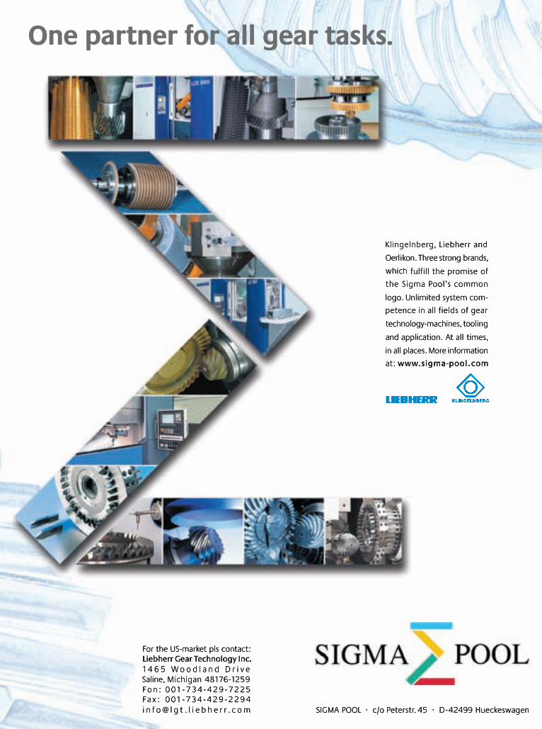
Klingelnberg, Liebherr and
Oerlikon. Three strong brands,
which fulfill the promise of
the Sigma Pool’s common
logo. Unlimited system com-
petence in all fields of gear
technology-machines, tooling
and application. At all times,
in all places. More information
at: www.sigma-pool .com
One partner for all gear tasks.
SIGMA POOL · c/o Peterstr. 45 · D-42499 Hueckeswagen
For the US-market pls contact:Liebherr Gear Technology Inc.1 4 6 5 W o o d l a n d D r i v eSaline, Michigan 48176-1259F o n : 0 01 - 7 3 4 - 4 2 9 - 7 2 2 5Fa x : 0 01 - 7 3 4 - 4 2 9 - 2 2 9 4i n f o @ l g t . l i e b h e r r . c o m
0408_Sigma_Anzeige 11.04.2005 14:22 Uhr Seite 1
April 2005 Gear Product News 055
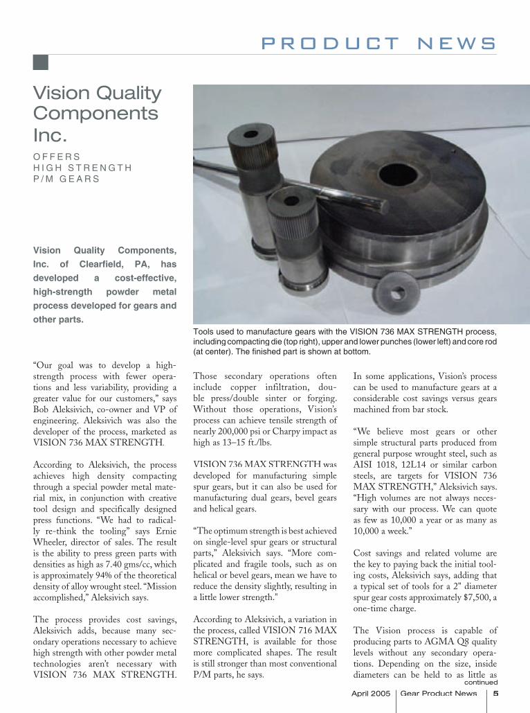
Tools used to manufacture gears with the VISION 736 MAX STRENGTH process,including compacting die (top right), upper and lower punches (lower left) and core rod (at center). The fi nished part is shown at bottom.
product news
“Our goal was to develop a high-strength process with fewer opera-tions and less variability, providing a greater value for our customers,” says Bob Aleksivich, co-owner and VP of engineering. Aleksivich was also the developer of the process, marketed as VISION 736 MAX STRENGTH.
According to Aleksivich, the process achieves high density compacting through a special powder metal mate-rial mix, in conjunction with creative tool design and specifically designed press functions. “We had to radical-ly re-think the tooling” says Ernie Wheeler, director of sales. The result is the ability to press green parts with densities as high as 7.40 gms/cc, which is approximately 94% of the theoretical density of alloy wrought steel. “Mission accomplished,” Aleksivich says.
The process provides cost savings, Aleksivich adds, because many sec-ondary operations necessary to achieve high strength with other powder metal technologies aren’t necessary with VISION 736 MAX STRENGTH.
Those secondary operations often include copper infiltration, dou-ble press/double sinter or forging. Without those operations, Vision’s process can achieve tensile strength of nearly 200,000 psi or Charpy impact as high as 13–15 ft./lbs.
VISION 736 MAX STRENGTH was developed for manufacturing simple spur gears, but it can also be used for manufacturing dual gears, bevel gears and helical gears.
“The optimum strength is best achieved on single-level spur gears or structural parts,” Aleksivich says. “More com-plicated and fragile tools, such as on helical or bevel gears, mean we have to reduce the density slightly, resulting in a little lower strength.”
According to Aleksivich, a variation in the process, called VISION 716 MAX STRENGTH, is available for those more complicated shapes. The result is still stronger than most conventional P/M parts, he says.
In some applications, Vision’s process can be used to manufacture gears at a considerable cost savings versus gears machined from bar stock.
“We believe most gears or other simple structural parts produced from general purpose wrought steel, such as AISI 1018, 12L14 or similar carbon steels, are targets for VISION 736 MAX STRENGTH,” Aleksivich says. “High volumes are not always neces-sary with our process. We can quote as few as 10,000 a year or as many as 10,000 a week.”
Cost savings and related volume are the key to paying back the initial tool-ing costs, Aleksivich says, adding that a typical set of tools for a 2" diameter spur gear costs approximately $7,500, a one-time charge.
The Vision process is capable of producing parts to AGMA Q8 quality levels without any secondary opera-tions. Depending on the size, inside diameters can be held to as little as
Vision Quality Components Inc.O F F E R S H I G H S T R E N G T H P / M G E A R S
Vision Quality Components, Inc. of Clearfi eld, PA, has developed a cost-effective, high-strength powder metal process developed for gears and other parts.
continued
6 Gear Product News April 2005 Gear Product News April 2005 Gear Product News April 2005
0.0015" total tolerance without bur-nishing or honing. Tolerances for overall length are approximately 0.005" total.
Parts manufactured using the process have many heat treatment options, including through-hardening and temper or case carburizing. Other possible post-manufacturing treat-ments include oil impregnation, black oxiding or steam treating.
Depending on the geometry, the proc-cess is capable of making gears with outside diameters up to 2–3" and thickness up to 1", says Wheeler. Also, Wheeler adds, Vision’s engineers can help customers optimize their designs for the powder metal process.
Vision has been making parts with this process for about a year and a half, Wheeler says, for customers in the gearmotor and hardware industries. Parts manufactured have included spur gears, dead bolt locks, hubs/cams, special fasteners and draw bars. A heli-cal gear is currently in a customer’s testing program.
Many other industries are potentials for the process, Wheeler says. Those include speed reducers, industrial trans-missions, power take-offs, gear pumps, and gear-driven motion control.
For more information:Vision Quality Components Inc.250 Technology DriveClearfield, PA 16830Phone: (614) 833-4489Fax: (614) 837-9549E-mail: [email protected]
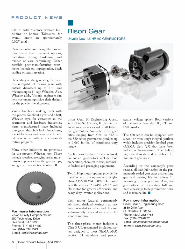
Bison GearUnveils New 1.5 HP AC GEARMOTORS
product news
Bison Gear & Engineering Corp., located in St. Charles, IL, has intro-duced an all-new series of parallel-shaft AC gearmotors. Available in five gear ratios ranging from 5.8:1 to 42.8:1, the 880 series gearmotors produce up to 1,060 in.-lbs. of continuous-duty torque.
Applications for these totally enclosed, fan-cooled gearmotors include food preparation, chemical mixers, automat-ic feeders and packaging equipment.
Two 1.5-hp motor options provide the specifier with the option of a single-phase 115/230 VAC 50/60 Hz motor or a three-phase 230/460 VAC 50/60 Hz motor for greater efficiencies and heavy-duty inverter applications.
Each motor features permanently lubricated, shielded bearings that have been preloaded to reduce end play and a dynamically balanced rotor shaft for smooth running.
The three-phase motor includes a Class F UL-recognized insulation sys-tem designed to meet NEMA MG1 Section 31 standards and protect
against voltage spikes. Both versions of the motor bear the UL, CE and CUL marks.
The 880 series can be equipped with a two- or three-stage integral gearbox, which includes precision hobbed gears (AGMA class Q9) that have been induction heat-treated. The helical high-speed mesh is skive hobbed for minimum gear noise.
According to the company’s press release, oil bath lubrication in the per-manently sealed gear cases assures long gear and bearing life and allows for mounting in any position. Also, the gearmotors use heavy-duty ball and needle bearings to help minimize noise and maximize life.
For more information:Bison Gear & Engineering Corp.3850 Ohio Ave.St. Charles, IL 60174Phone: (800) 282-4766Fax: (630) 377-6777E-mail: [email protected]: www.bisongear.com
April 2005 Gear Product News 7
G E A R S & G E A R D R I V E S
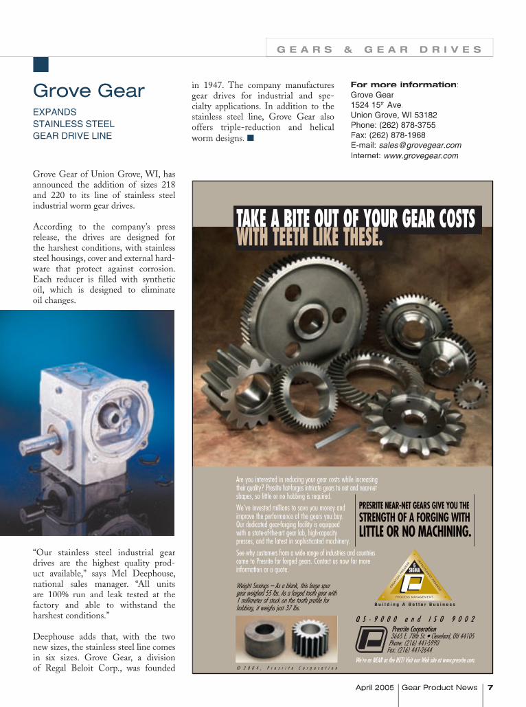
Grove Gear of Union Grove, WI, has announced the addition of sizes 218 and 220 to its line of stainless steel industrial worm gear drives.
According to the company’s press release, the drives are designed for the harshest conditions, with stainless steel housings, cover and external hard-ware that protect against corrosion. Each reducer is filled with synthetic oil, which is designed to eliminate oil changes.
“Our stainless steel industrial gear drives are the highest quality prod-uct available,” says Mel Deephouse, national sales manager. “All units are 100% run and leak tested at the factory and able to withstand the harshest conditions.”
Deephouse adds that, with the two new sizes, the stainless steel line comes in six sizes. Grove Gear, a division of Regal Beloit Corp., was founded
in 1947. The company manufactures gear drives for industrial and spe-cialty applications. In addition to the stainless steel line, Grove Gear also offers triple-reduction and helical worm designs.
Grove GearEXPANDS STAINLESS STEEL GEAR DRIVE LINE
For more information:Grove Gear1524 15th Ave.Union Grove, WI 53182Phone: (262) 878-3755Fax: (262) 878-1968E-mail: [email protected]: www.grovegear.com
8 Gear Product News April 2005 Gear Product News April 2005 Gear Product News April 2005
product news
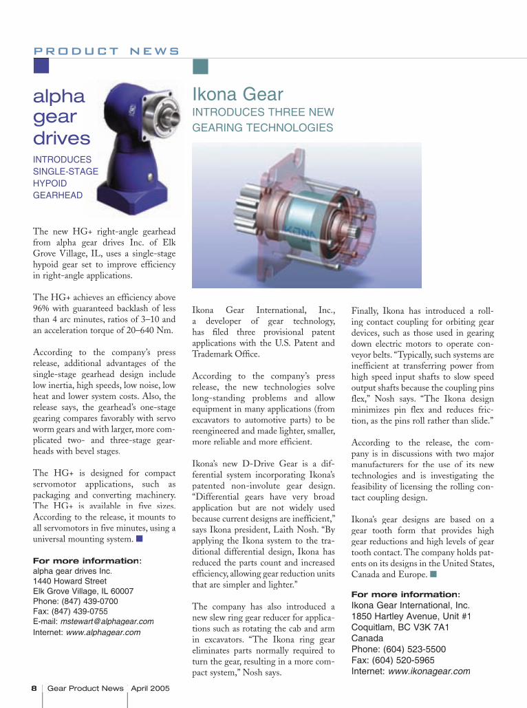
The new HG+ right-angle gearhead from alpha gear drives Inc. of Elk Grove Village, IL, uses a single-stage hypoid gear set to improve efficiency in right-angle applications.
The HG+ achieves an efficiency above 96% with guaranteed backlash of less than 4 arc minutes, ratios of 3–10 and an acceleration torque of 20–640 Nm.
According to the company’s press release, additional advantages of the single-stage gearhead design include low inertia, high speeds, low noise, low heat and lower system costs. Also, the release says, the gearhead’s one-stage gearing compares favorably with servo worm gears and with larger, more com-plicated two- and three-stage gear-heads with bevel stages.
The HG+ is designed for compact servomotor applications, such as packaging and converting machinery. The HG+ is available in five sizes. According to the release, it mounts to all servomotors in five minutes, using a universal mounting system.
For more information:alpha gear drives Inc.1440 Howard StreetElk Grove Village, IL 60007Phone: (847) 439-0700Fax: (847) 439-0755E-mail: [email protected]: www.alphagear.com
alpha geardrivesINTRODUCES SINGLE-STAGE HYPOID GEARHEAD
Ikona Gear International, Inc., a developer of gear technology, has fi led three provisional patent applications with the U.S. Patent and Trademark Offi ce.
According to the company’s press release, the new technologies solve long-standing problems and allow equipment in many applications (from excavators to automotive parts) to be reengineered and made lighter, smaller, more reliable and more efficient.
Ikona’s new D-Drive Gear is a dif-ferential system incorporating Ikona’s patented non-involute gear design. “Differential gears have very broad application but are not widely used because current designs are inefficient,” says Ikona president, Laith Nosh. “By applying the Ikona system to the tra-ditional differential design, Ikona has reduced the parts count and increased efficiency, allowing gear reduction units that are simpler and lighter.”
The company has also introduced a new slew ring gear reducer for applica-tions such as rotating the cab and arm in excavators. “The Ikona ring gear eliminates parts normally required to turn the gear, resulting in a more com-pact system,” Nosh says.
Finally, Ikona has introduced a roll-ing contact coupling for orbiting gear devices, such as those used in gearing down electric motors to operate con-veyor belts. “Typically, such systems are inefficient at transferring power from high speed input shafts to slow speed output shafts because the coupling pins flex,” Nosh says. “The Ikona design minimizes pin flex and reduces fric-tion, as the pins roll rather than slide.”
According to the release, the com-pany is in discussions with two major manufacturers for the use of its new technologies and is investigating the feasibility of licensing the rolling con-tact coupling design.
Ikona’s gear designs are based on a gear tooth form that provides high gear reductions and high levels of gear tooth contact. The company holds pat-ents on its designs in the United States, Canada and Europe.
For more information:Ikona Gear International, Inc.1850 Hartley Avenue, Unit #1Coquitlam, BC V3K 7A1CanadaPhone: (604) 523-5500Fax: (604) 520-5965Internet: www.ikonagear.com
Ikona GearINTRODUCES THREE NEW GEARING TECHNOLOGIES
April 2005 Gear Product News 9
G E A R S & G E A R D R I V E S
A gear manufacturer recently cameto M.A. Ford Mfg. Co. Inc. with a problem. The company needed to increase productivity in one of its machining cells.
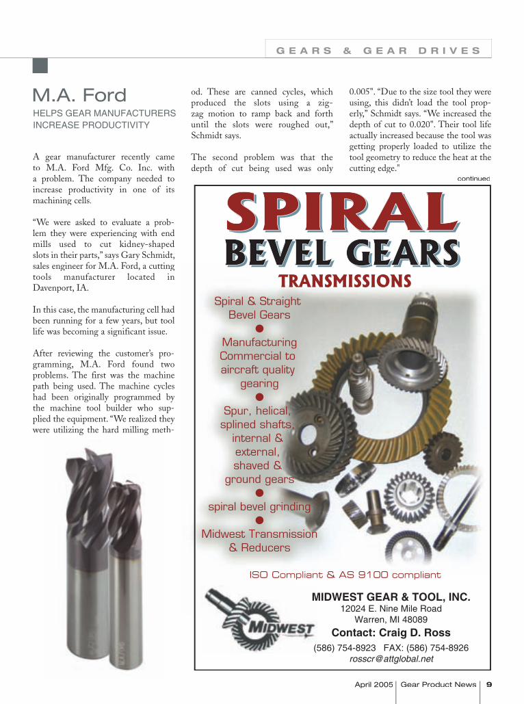
“We were asked to evaluate a prob-lem they were experiencing with end mills used to cut kidney-shaped slots in their parts,” says Gary Schmidt, sales engineer for M.A. Ford, a cuttingtools manufacturer located in Davenport, IA.
In this case, the manufacturing cell had been running for a few years, but tool life was becoming a significant issue.
After reviewing the customer’s pro-gramming, M.A. Ford found two problems. The first was the machine path being used. The machine cycles had been originally programmed by the machine tool builder who sup-plied the equipment. “We realized they were utilizing the hard milling meth-
od. These are canned cycles, which produced the slots using a zig-zag motion to ramp back and forth until the slots were roughed out,” Schmidt says.
The second problem was that the depth of cut being used was only
M.A. FordHELPS GEAR MANUFACTURERS INCREASE PRODUCTIVITY
0.005". “Due to the size tool they were using, this didn’t load the tool prop-erly,” Schmidt says. “We increased the depth of cut to 0.020". Their tool life actually increased because the tool was getting properly loaded to utilize the tool geometry to reduce the heat at the cutting edge.”
continued
Spiral & Straight Bevel Gears
�
ManufacturingCommercial to aircraft quality
gearing�
Spur, helical, splined shafts,
internal & external, shaved &
ground gears�
spiral bevel grinding�
Midwest Transmission& Reducers
TRANSMISSIONS
ISO Compliant & AS 9100 compliant
SPIRALBEVEL GEARSSPIRALBEVEL GEARS
MIDWEST GEAR & TOOL, INC.12024 E. Nine Mile Road
Warren, MI 48089Contact: Craig D. Ross
(586) 754-8923 FAX: (586) [email protected]
10 Gear Product News April 2005 Gear Product News April 2005
product news
MetrologyResourcePresents Solution For Evaluating Shaft Seals
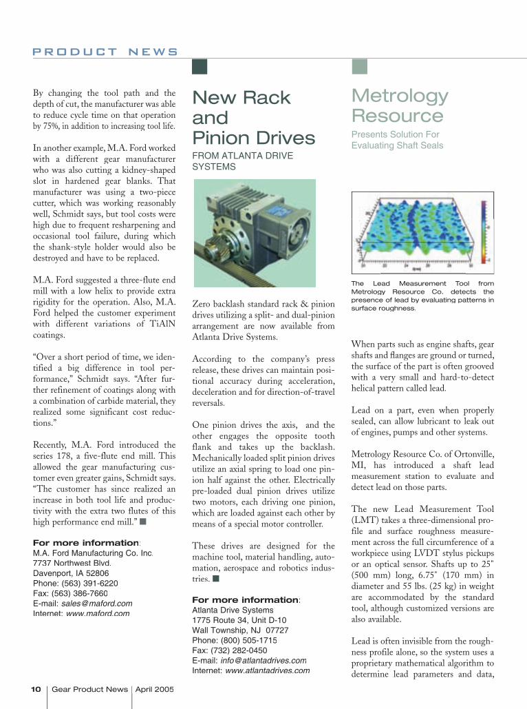
Zero backlash standard rack & pinion drives utilizing a split- and dual-pinion arrangement are now available from Atlanta Drive Systems.
According to the company’s press release, these drives can maintain posi-tional accuracy during acceleration, deceleration and for direction-of-travel reversals.
One pinion drives the axis, and the other engages the opposite tooth flank and takes up the backlash. Mechanically loaded split pinion drives utilize an axial spring to load one pin-ion half against the other. Electrically pre-loaded dual pinion drives utilize two motors, each driving one pinion, which are loaded against each other by means of a special motor controller.
These drives are designed for the machine tool, material handling, auto-mation, aerospace and robotics indus-tries.
For more information:Atlanta Drive Systems1775 Route 34, Unit D-10Wall Township, NJ 07727Phone: (800) 505-1715Fax: (732) 282-0450E-mail: [email protected]: www.atlantadrives.com
New Rack andPinion Drives FROM ATLANTA DRIVE SYSTEMS
By changing the tool path and the depth of cut, the manufacturer was able to reduce cycle time on that operation by 75%, in addition to increasing tool life.
In another example, M.A. Ford worked with a different gear manufacturer who was also cutting a kidney-shaped slot in hardened gear blanks. That manufacturer was using a two-piece cutter, which was working reasonably well, Schmidt says, but tool costs were high due to frequent resharpening and occasional tool failure, during which the shank-style holder would also be destroyed and have to be replaced.
M.A. Ford suggested a three-flute end mill with a low helix to provide extra rigidity for the operation. Also, M.A. Ford helped the customer experiment with different variations of TiAlN coatings.
“Over a short period of time, we iden-tified a big difference in tool per-formance,” Schmidt says. “After fur-ther refinement of coatings along with a combination of carbide material, they realized some significant cost reduc-tions.”
Recently, M.A. Ford introduced the series 178, a five-flute end mill. This allowed the gear manufacturing cus-tomer even greater gains, Schmidt says. “The customer has since realized an increase in both tool life and produc-tivity with the extra two flutes of this high performance end mill.”
For more information:M.A. Ford Manufacturing Co. Inc.7737 Northwest Blvd.Davenport, IA 52806Phone: (563) 391-6220Fax: (563) 386-7660E-mail: [email protected]: www.maford.com
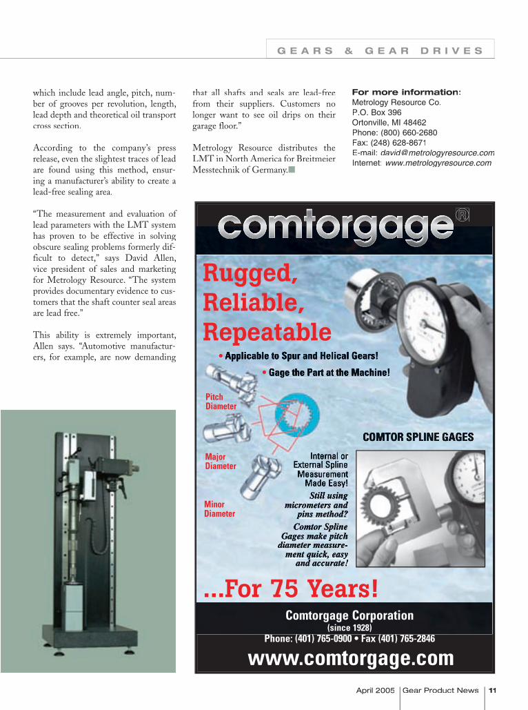
When parts such as engine shafts, gear shafts and fl anges are ground or turned, the surface of the part is often grooved with a very small and hard-to-detect helical pattern called lead.
Lead on a part, even when properly sealed, can allow lubricant to leak out of engines, pumps and other systems.
Metrology Resource Co. of Ortonville, MI, has introduced a shaft lead measurement station to evaluate and detect lead on those parts.
The new Lead Measurement Tool (LMT) takes a three-dimensional pro-file and surface roughness measure-ment across the full circumference of a workpiece using LVDT stylus pickups or an optical sensor. Shafts up to 25"(500 mm) long, 6.75" (170 mm) in diameter and 55 lbs. (25 kg) in weight are accommodated by the standard tool, although customized versions are also available.
Lead is often invisible from the rough-ness profile alone, so the system uses a proprietary mathematical algorithm to determine lead parameters and data,
The Lead Measurement Tool from Metrology Resource Co. detects the presence of lead by evaluating patterns in surface roughness.
April 2005 Gear Product News 11
G E A R S & G E A R D R I V E S
that all shafts and seals are lead-free from their suppliers. Customers no longer want to see oil drips on their garage floor.”
Metrology Resource distributes the LMT in North America for Breitmeier Messtechnik of Germany.
For more information:Metrology Resource Co.P.O. Box 396Ortonville, MI 48462Phone: (800) 660-2680Fax: (248) 628-8671E-mail: [email protected]: www.metrologyresource.com
www.comtorgage.com
®
Rugged,Reliable,Repeatable
...For 75 Years!
Internal orExternal SplineMeasurement
Made Easy!Still using
micrometers andpins method?
Comtor SplineGages make pitch
diameter measure-ment quick, easy
and accurate!
Comtorgage Corporation (since 1928)
Phone: (401) 765-0900 • Fax (401) 765-2846
PitchDiameter
MajorDiameter
MinorDiameter
• Applicable to Spur and Helical Gears!
• Gage the Part at the Machine!
COMTOR SPLINE GAGES
which include lead angle, pitch, num-ber of grooves per revolution, length, lead depth and theoretical oil transport cross section.
According to the company’s press release, even the slightest traces of lead are found using this method, ensur-ing a manufacturer’s ability to create a lead-free sealing area.
“The measurement and evaluation of lead parameters with the LMT system has proven to be effective in solving obscure sealing problems formerly dif-ficult to detect,” says David Allen, vice president of sales and marketing for Metrology Resource. “The system provides documentary evidence to cus-tomers that the shaft counter seal areas are lead free.”
This ability is extremely important, Allen says. “Automotive manufactur-ers, for example, are now demanding
12 Gear Product News April 2005 Gear Product News April 2005
product news
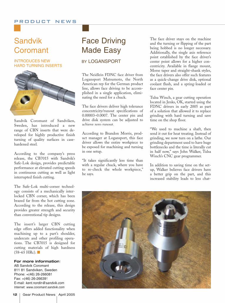
The Neidlein FDNC face driver from Logansport Matsumoto, the North American rep for the German product line, allows face driving to be accom-plished in a single application, elimi-nating the need for a chuck.
The face drivers deliver high tolerance concentricity/runout specifications of 0.00003–0.0007. The center pin and drive disk system can be adjusted to achieve zero runout.
According to Brandon Morris, prod-uct manager at Logansport, this face driver allows the entire workpiece to be exposed for machining and turning in one setup.
“It takes significantly less time than with a regular chuck, where you have to re-check the whole workpiece,” he says.
The face driver stays on the machine and the turning or flipping of the part being hobbed is no longer necessary. Additionally, the single axis reference point established by the face driver’s center point allows for a higher con-centricity. Available in flange mount, Morse taper and straight-shank styles, the face drivers also offer such features as a quick-change drive disk, optional coolant flush, and a spring-loaded or face center pin.
Tulsa Winch, a gear cutting operation located in Jenks, OK, started using the FDNC drivers in early 2005 as part of a solution that allowed it to replace grinding with hard turning and save time on the shop floor.
“We used to machine a shaft, then send it out for heat treating. Instead of grinding, we now turn on a lathe. Our grinding department used to have huge bottlenecks and the time is literally cut in half now,” says John Walker, Tulsa Winch’s CNC gear programmer.
In addition to saving time on the set-up, Walker believes face drivers have a better grip on the part, and this increased stability leads to less chat-
Face Driving Made Easy BY LOGANSPORT
Sandvik Coromant of Sandviken, Sweden, has introduced a new range of CBN inserts that were de-veloped for highly productive finish turning of quality surfaces in case-hardened steel.
According to the company’s press release, the CB7015 with Sandvik’s Safe-Lok design, provides predictable performance at elevated cutting speeds in continuous cutting as well as light interrupted finish cutting.
The Safe-Lok multi-corner technol-ogy consists of a mechanically inter-locked CBN corner, which has been brazed far from the hot cutting zone. According to the release, this design provides greater strength and security than conventional tip designs.
The insert’s larger CBN cutting edge offers added functionality when machining up to a part’s shoulder, undercuts and other profiling opera-tions. The CB7015 is designed for cutting materials of high hardness (58–65 HRc).
For more information:AB Sandvik Coromant811 81 Sandviken, SwedenPhone: +(46) 26-266081Fax: +(46) 26-266391E-mail: [email protected]: www.coromant.sandvik.com
Sandvik CoromantINTRODUCES NEW HARD TURNING INSERTS
April 2005 Gear Product News 13
G E A R S & G E A R D R I V E S
ter. Walker explains, “When you have chatter problems, you have to add a pass on the lathe and all of this makes the production time even longer.”
The use of face drivers has also helped make the shop more flexible, Walker says. Instead of machining the shafts on a gear shaper, the company now also has the option of using a hobbing machine with the face driver. “We can now hob or shape regardless of what machine is tied up at the moment. The set-up time is highly reduced and the cost is very reasonable,” Walker says.
For more information:Logansport Matsumoto Co.P.O. Box 7006Logansport, IN 46947-7006 Telephone: (574) 735-0225Fax: (574) 722-6559E-Mail: [email protected]: www.logan-mmk.com
Italian born company based in Mexico City serving North America since 1969.
1811 Newton Street Austin, Texas 78704
Phone: 512-443-6314 Fax: 512-707-1226Call Jim Stockbauer
In A Rising Cost Environment
Cutting Costs Is Mandatory…
New and repaired gear reducers
from 1 HP to 6000 HP
Helical gears ground to AGMA 13
Spiral bevel right angle drives
(most major cooling tower drives available)
Call or email for competitive quote. Loose gearsets manufactured
to your spec.
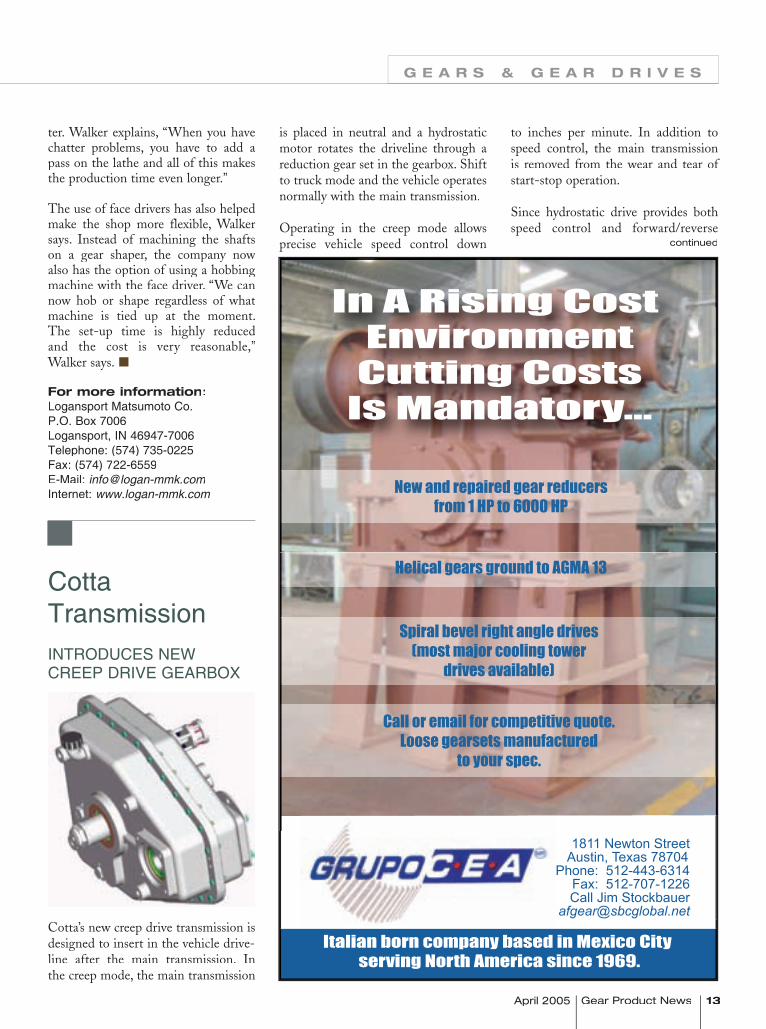
Cotta Transmission
INTRODUCES NEW CREEP DRIVE GEARBOX
Cotta’s new creep drive transmission is designed to insert in the vehicle drive-line after the main transmission. In the creep mode, the main transmission
is placed in neutral and a hydrostatic motor rotates the driveline through a reduction gear set in the gearbox. Shift to truck mode and the vehicle operates normally with the main transmission.
Operating in the creep mode allows precise vehicle speed control down
to inches per minute. In addition to speed control, the main transmission is removed from the wear and tear of start-stop operation.
Since hydrostatic drive provides both speed control and forward/reverse
continued
14 Gear Product News April 2005 Gear Product News April 2005
product news G E A R S & G E A R D R I V E S
capability, the creepdrive system is well-suited for integration into remote control systems.
Applications include refuse trucks, paint stripers, cement trucks, post-hole diggers, de-icer trucks, water blasters and similar applications.
For more information:Cotta Transmission Co.1301 Prince Hall Dr.Beloit, WI 53511-4439Telephone: (608) 368-5600Fax: (608) 368-5605E-Mail: [email protected]: www.cotta.com
HD Systems INTRODUCES NEW GEARHEAD
The new Quantum Series harmon-ic drive size 32 gearhead from HD Systems has 50% more torque, zero backlash, and 1 arc-min. accuracy.
The Quantum Series is the highest torque capacity harmonic drive gear-head ever produced. It delivers 50% more torque than the CSF Series while maintaining zero backlash, 1 arc-min positional accuracy, and +/–positional accuracy, and +/–positional accuracy, and +/ 5 arc-sec. repeatability.
The Quantum Series size 32 gear-head has an outer diameter of 138 mm and is 62 mm in length. It has a rated torque of 1,575 in.-lbs. and a maximum torque of 7,890 in.-lbs. It is available in gear ratios of 50, 80, 100, 120 and 160:1.
For more information:HD Systems Inc.89 Cabot Ct.Hauppauge, NY 11788Telephone: (800) 231-HDSIFax: (631) 231-6803E-Mail: [email protected]
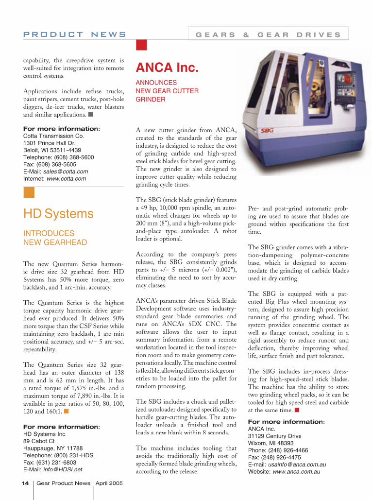
ANCA Inc.ANNOUNCES NEW GEAR CUTTER GRINDER
A new cutter grinder from ANCA, A new cutter grinder from ANCA, created to the standards of the gear created to the standards of the gear industry, is designed to reduce the cost industry, is designed to reduce the cost of grinding carbide and high-speed of grinding carbide and high-speed steel stick blades for bevel gear cutting. steel stick blades for bevel gear cutting. The new grinder is also designed to The new grinder is also designed to improve cutter quality while reducing improve cutter quality while reducing grinding cycle times.
The SBG (stick blade grinder) features a 49 hp, 10,000 rpm spindle, an auto-matic wheel changer for wheels up to 200 mm (8"), and a high-volume pick-and-place type autoloader. A robot loader is optional.
According to the company’s press release, the SBG consistently grinds parts to +/– 5 microns (+/– 0.002"), eliminating the need to sort by accu-racy classes.
ANCA’s parameter-driven Stick Blade Development software uses industry-standard gear blade summaries and runs on ANCA’s 5DX CNC. The software allows the user to input summary information from a remote workstation located in the tool inspec-tion room and to make geometry com-pensations locally. The machine control is flexible, allowing different stick geom-etries to be loaded into the pallet for random processing.
The SBG includes a chuck and pallet-ized autoloader designed specifically to handle gear-cutting blades. The auto-loader unloads a finished tool and loads a new blank within 8 seconds.
The machine includes tooling that avoids the traditionally high cost of specially formed blade grinding wheels, according to the release.
Pre- and post-grind automatic prob-ing are used to assure that blades are ground within specifications the first time.
The SBG grinder comes with a vibra-tion-dampening polymer-concrete base, which is designed to accom-modate the grinding of carbide blades used in dry cutting.
The SBG is equipped with a pat-ented Big Plus wheel mounting sys-tem, designed to assure high precision running of the grinding wheel. The system provides concentric contact as well as flange contact, resulting in a rigid assembly to reduce runout and deflection, thereby improving wheel life, surface finish and part tolerance.
The SBG includes in-process dress-ing for high-speed-steel stick blades. The machine has the ability to store two grinding wheel packs, so it can be tooled for high speed steel and carbide at the same time.
For more information:ANCA Inc.31129 Century DriveWixom, MI 48393Phone: (248) 926-4466Fax: (248) 926-4475E-mail: [email protected]: www.anca.com.au

PRODUCT SHOWCASE GEARS & GEAR DRIVES
April 2005 Gear Product News 15
Presrite Corporation3665 East 78th Street • Cleveland, OH 44105-2048
216.441.5990 FAX: 216.441.2644E-Mail: [email protected] • Web Site: www.presrite.com
PRESRITE FORGING BROCHURE
Presrite Corporation’s eight-page color brochure provides an overview of the company’s forging capabilities, and
information on its equipment and its three forging plants. It also identifies industries
served and customer benefits. Presrite produces minimum-draft, net- and near-
net-shape forgings up to 300 lbs. and 18 inches in diameter.
Ikona Gear InternationalInnovative designs in planetary gears & systems. Breakthrough
inventions in actuators, couplings, & slew drives (patented).
Design Features/Advantages• Size & weight reduction• Can be manufactured in plastic• High single-stage reduction • Zero backlash for extreme precision• Patented, licensable on exclusive basis• Custom design & FEA Custom design & FEA
www.ikonagear.com
www.gearproductnews.com
The complete issue, every issue, always available onlinePlus
● Subscriptions ● Advertising Information ● FREE Buyers Guide Listings
Bookmark Us Today!
YOUR AD IN THE POWER TRANSMISSION
BUYERS GUIDEWon't You Join Us
Next Issue in June?Contact:
Randall Publishing, Inc.1425 Lunt Ave.
Randall Publishing, Inc.1425 Lunt Ave.
Randall Publishing, Inc.
Elk Grove Village, IL 60007 USAPhone: (847) 437-6604
Elk Grove Village, IL 60007 USAPhone: (847) 437-6604
Elk Grove Village, IL 60007 USA
Fax: (847) 437-6618E-mail: [email protected]
16 Gear Product News April 2005 Gear Product News April 2005 Gear Product News April 2005
Capstan AtlanticS O U N D WAV E S T H AT M E A S U R E Q U A L I T Y
For almost a year now, Capstan For almost a year now, Capstan FFor almost a year now, Capstan FAtlantic has been using state-of-the-art technology that utilizes sound to completely and reliably test product quality.
“The RAM NDT unit we’ve employed in our manufacturing process has enabled us to provide one hundred percent product testing,” says vice pres-ident of engineering Rich Slattery. “To put it simply, it provides a peace of mind that lets us sleep at night.”
That high confidence level is the main reason that the test system’s manufac-turer, The Modal Shop of Cincinnati, OH, boasts that sales of the RAM NDT have grown at a rate of 100% annually since its introduction in 2002. According to Scott Sorensen, the company’s marketing manager, the customer list includes prominent gear, transmission and powder metallurgy specialists.
As a manufacturer of multi-level, high performance precision gears for auto-motive powertrain systems, Capstan Atlantic fits well into this niche. They supply parts for the Big Three automo-tive makers in the United States, as well as Japanese transplant facilities.
Pressing Need for Gear Production
Capstan Atlantic’s production facility involves a complex metallurgy process that begins with an iron-based, pow-dered alloy. Additions such as chrome, nickel, molybdenum and graphite are added for strength, ductility and wear resistance. The powder blends are compressed to varying densities, depending on the requirements of the application. The newly formed gears
are then sintered on 65' continuous belt furnaces at a temperature higher than 2,000°F. Although the meth-ods Capstan Atlantic employs are very robust and effectively minimize the chance of defects, the process still requires a 100% test for structural integrity. Therefore, product testing is an essential element in the quality assurance program.
Prior to investing in the RAM NDT unit, the company used a non-destruc-tive, 100% torque test method. But it didn’t deliver the level of per-formance and reliability that put com-pany minds at ease. It was subject to human interpretation, it was very slow and therefore costly, and it didn’t guar-antee 100% conformance.
“We felt that the manual testing approach was too uncertain for us,” says senior development engineer Eric Day. “Because of the demanding, high-ly competitive nature of our industry, we wanted a testing method that quali-fied every single component that left our facility. We found it with the RAM NDT unit. It has made a powerful impact on our company and signifi-cantly added to our peace of mind.”
“Our previous method tested around 40–50 parts an hour,” Slattery says. “But the RAM NDT unit tests 600–700 parts an hour. The improvement in the level of effectiveness and efficien-cy we’ve experienced with the RAM NDT is phenomenal.”
Sound Approach to Product Testing
To understand how the RAM NDT unit works, consider the operation behind a bell or tuning fork. When
you strike either instrument, it vibrates, emitting a sound. An instrument that rings true produces a consistent sound. And this consistency in sound reveals the structural integrity of the instru-ment. Just like a cracked bell will not ring true, components can be tested in the same manner.
That is the basis for RAM NDT tech-nology. When struck by a tiny anvil, components like gears emit a natural frequency as part of their structural response. This unique and measurable signature is then compared and analyzed against both good and bad product. If a gear is cracked, lacks the correct den-
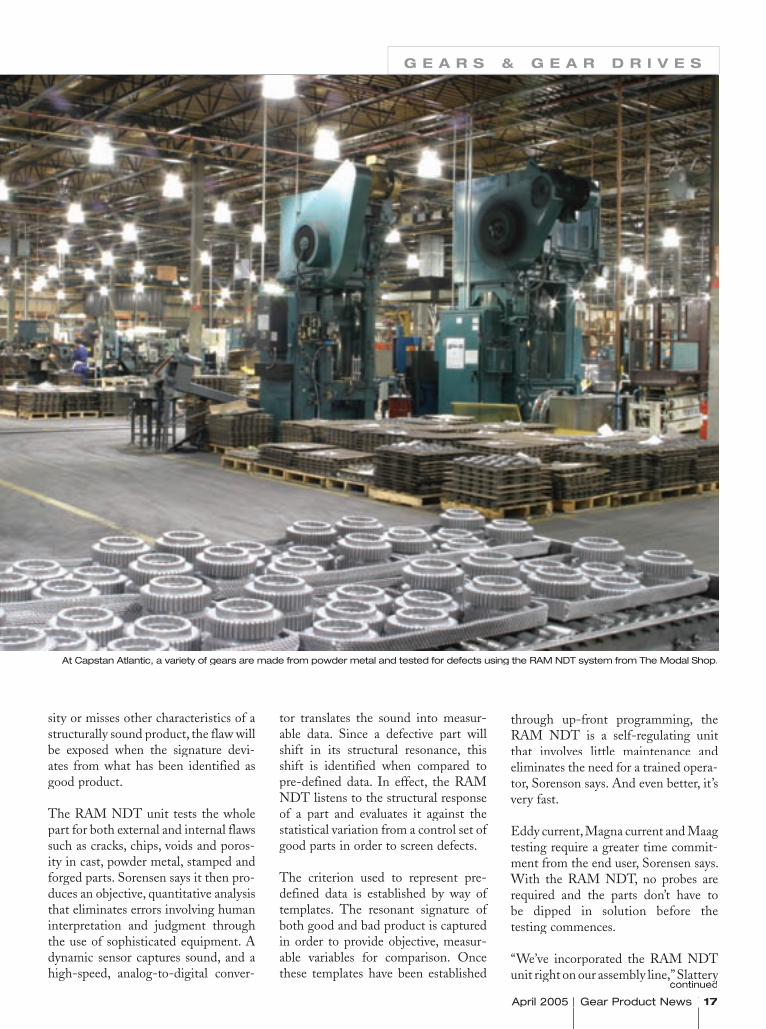
At Capstan Atlantic, a variety of gears are made from powder metal and tested for defects using the RAM NDT system from The Modal Shop.
April 2005 Gear Product News 17 April 2005 Gear Product News April 2005 Gear Product News
sity or misses other characteristics of a structurally sound product, the flaw will be exposed when the signature devi-ates from what has been identified as good product.
The RAM NDT unit tests the whole part for both external and internal flaws such as cracks, chips, voids and poros-ity in cast, powder metal, stamped and forged parts. Sorensen says it then pro-duces an objective, quantitative analysis that eliminates errors involving human interpretation and judgment through the use of sophisticated equipment. A dynamic sensor captures sound, and a high-speed, analog-to-digital conver-
tor translates the sound into measur-able data. Since a defective part will shift in its structural resonance, this shift is identified when compared to pre-defined data. In effect, the RAM NDT listens to the structural response of a part and evaluates it against the statistical variation from a control set of good parts in order to screen defects.
The criterion used to represent pre-defined data is established by way of templates. The resonant signature of both good and bad product is captured in order to provide objective, measur-able variables for comparison. Once these templates have been established
through up-front programming, the RAM NDT is a self-regulating unit that involves little maintenance and eliminates the need for a trained opera-tor, Sorenson says. And even better, it’s very fast.
Eddy current, Magna current and Maag testing require a greater time commit-ment from the end user, Sorensen says. With the RAM NDT, no probes are required and the parts don’t have to be dipped in solution before the testing commences.
“We’ve incorporated the RAM NDT unit right on our assembly line,” Slattery
G E A R S & G E A R D R I V E S
continuedunit right on our assembly line,” Slattery
continuedunit right on our assembly line,” Slattery

18 Gear Product News April 2005 Gear Product News April 2005 Gear Product News April 2005
says. “It doesn’t slow our production one bit. Components pass through it right before packaging. Any product that doesn’t pass inspection is removed from the line automatically. And gears that pass inspection are imme-diately packaged and shipped in a streamlined operation.”
According to Sorensen, manufactur-ers need not worry about durability either. From the rugged microphone and industrial electric impactor to the NEMA smart digital controller, the RAM NDT is designed for industrial environments. Its durable, physical construction is suitable for plant-floor, high-volume test applications.
Benefi ts—Right on PitchFor Capstan Atlantic, the RAM NDT not only contributes to peace of mind; it also contributes to the bottom line. According to Slattery, its RAM NDT
system saves the company “33 cents on each gear produced over the previous method.” And since the company ships around 5,000 gears a day, that amounts to a total savings of $1,660 per day. Furthermore, since the unit eliminates the need for a specially trained opera-tor, it also reduces personnel costs. But
the best part is in knowing the com-pany has achieved the highest level of quality assurance possible.
“When I go home at the end of the day, I don’t spend the night worrying about whether or not a gear slipped through our quality system and was shipped to a customer because I know every single gear produced on our line has been thoroughly and completely tested. It’s hard to put a price tag on that,” Slattery says. “But it is easy to figure the consequences involved in a field failure. That’s every manufactur-er’s worst nightmare.”
For Capstan Atlantic, a defective part in a drivetrain system represents a cus-tomer “walk home.” In other words, the automobile breaks down, leaving the occupants stranded. In this scenar-io, the cost of tear-down and customer reimbursement could easily exceed the
Newly formed gears are sintered on 65' continuous belt furnaces at a temperature over 2,000° F.
April 2005 Gear Product News 19 April 2005 Gear Product News April 2005 Gear Product News
purchase price of the RAM NDT unit. But that’s really only the minimum effect. And it involves proving that the defective part was an isolated event. Because otherwise, it might result in a recall—an ordeal that could easily put a company out of business.
“With our present system in place, I’m confident that everything checks out as it should,” Day says. “The level of quality assurance is far superior to our previous method.”
RAM NDT packages are available with a variety of options, from the $23,000 manual systems package to the mid-range, semi-automated system with-out a conveyor that runs at $34,000, to the totally automated RAM NDT at $55,000.
Although there was a learning curve ini-tially, once Capstan Atlantic employees
mastered the new system, they found it relatively easy to use. And not only did it require less engineering support, but also the data captured by the RAM NDT provided feedback that contrib-uted to other quality improvements.
“We discovered that additionally, the unit has enabled us to recognize things about our process and make improve-ments upstream that have increased our product yield by reducing process variation,” Slattery says.
For more information:The Modal Shop Inc.3149 E. Kemper Dr.Cincinnati, OH 45241Telephone: (513) 351-9919Fax: (513) 458-2172E-mail: [email protected]: www.modalshop.com
Capstan Atlantic 10 Cushing Dr.Wrentham, MA 02093Telephone: (508) 384-3100Fax: (508) 384-3196E-mail: [email protected]: www.capstanatlantic.com
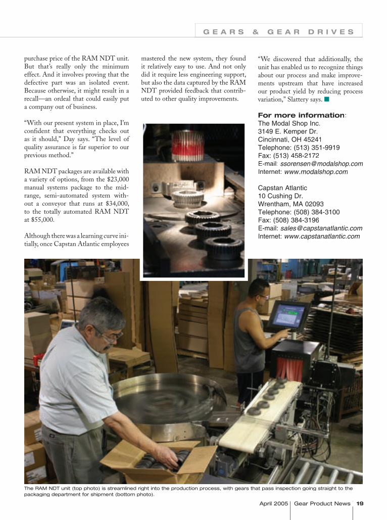
The RAM NDT unit (top photo) is streamlined right into the production process, with gears that pass inspection going straight to the packaging department for shipment (bottom photo).
G E A R S & G E A R D R I V E S
20 Gear Product News April 2005 Gear Product News April 2005 Gear Product News April 2005
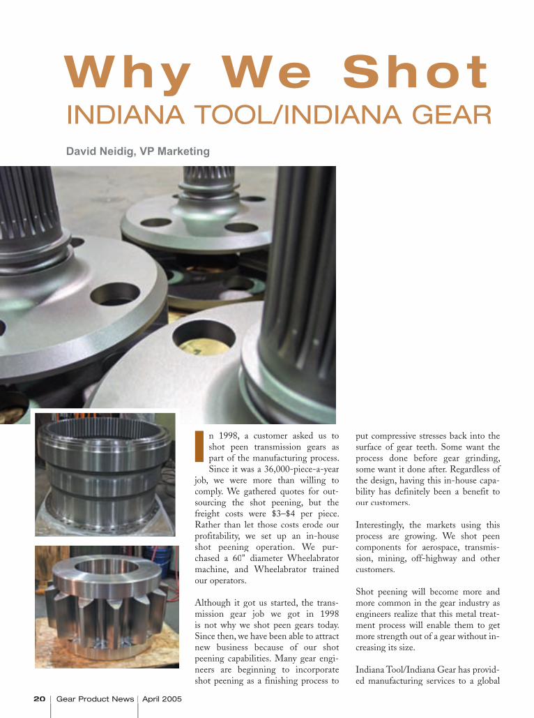
n 1998, a customer asked us to shot peen transmission gears as part of the manufacturing process. Since it was a 36,000-piece-a-year
job, we were more than willing to comply. We gathered quotes for out-sourcing the shot peening, but the freight costs were $3–$4 per piece. Rather than let those costs erode our profitability, we set up an in-house shot peening operation. We pur-chased a 60" diameter Wheelabrator machine, and Wheelabrator trained our operators.
Although it got us started, the trans-mission gear job we got in 1998 is not why we shot peen gears today. Since then, we have been able to attract new business because of our shot peening capabilities. Many gear engi-neers are beginning to incorporate shot peening as a finishing process to
put compressive stresses back into the surface of gear teeth. Some want the process done before gear grinding, some want it done after. Regardless of the design, having this in-house capa-bility has definitely been a benefit to our customers.
Interestingly, the markets using this process are growing. We shot peen components for aerospace, transmis-sion, mining, off-highway and other customers.
Shot peening will become more and more common in the gear industry as engineers realize that this metal treat-ment process will enable them to get more strength out of a gear without in-creasing its size.
Indiana Tool/Indiana Gear has provid-ed manufacturing services to a global
Why We Shot Peen GearsINDIANA TOOL/INDIANA GEARDavid Neidig, VP Marketing
I
April 2005 Gear Product News 21 2005 Gear Product News 2005 Gear Product News
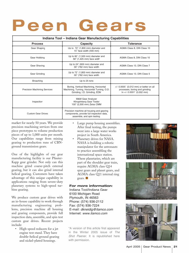
• Large pump housing assemblies. After final testing, the pumps went into a large water works project in South America. • Planetary drives for NASA. NASA is building a robotic manipulator for the astronauts to practice assembling the international space station. These planetaries, which are part of the shoulder gear train, require AGMA class Q14 spur gears and planet gears, and AGMA class Q11 internal ring gears.
For more information:Indiana Tool/Indiana Gear6100 Michigan RoadPlymouth, IN 46563Phone: (574) 936-2112Fax: (574) 936-7224E-mail: [email protected]: www.itamco.com
Why We Shot Peen Gears
market for nearly 50 years. We provide precision machining services from one piece prototypes to volume production pieces of up to 1,000 units per month. Our capabilities range from mining gearing to production runs of CBN-ground transmission gears.
One of the highlights of our gear manufacturing facility is our Pfauter-Kapp gear grinder. Not only can this machine grind coarse-pitch external gearing, but it can also grind internal helical gearing. Customers have taken advantage of this unique capability in applications ranging from severe-duty planetary systems to high-speed tur-bine gearing.
We produce custom gear drives with an in-house capability to work through manufacturing engineering prob-lems, precision machine all housing and gearing components, provide full inspection data, assemble, and spin test custom gear drives. Recent projects include: • High-speed reducers for a jet engine test stand. They have double-helical ground gearing and nickel-plated housings.
*A version of this article first appeared in the Winter 2005 issue of The Shot Peener. It is republished here with permission.
Indiana Tool – Indiana Gear Manufacturing CapabilitiesProcess Capacity Tolerance
Gear Shaping Up to 72" (1,800 mm) diameter and 15" face width (400 mm)
AGMA Class 8, DIN Class 10
Gear Hobbing Up to 60" (1,500 mm) diameter and 56" (1,425 mm) face width AGMA Class 8, DIN Class 10
Gear Shaving Up to 24" (600 mm) diameter and 30" (762 mm) face width AGMA Class 13, DIN Class 7
Gear Grinding Up to 72" (1,800 mm) diameter and 30" (762 mm) face width AGMA Class 13, DIN Class 5
Broaching Up to 25 tons
Precision Machining ServicesBoring, Vertical Machining, Horizontal
Machining, Turning, Horizontal Turning, O.D. Grinding, I.D. Grinding, EDM
+/- 0.0005" (0.012 mm) or better on all processes, boring and grinding
to +/- 0.0001" (0.002 mm)
InspectionM&M Gear Analyzer
Klingelnberg Gear Tester100" (2,500 mm) Zeiss CMM
Custom Gear DrivesPrecision machine all housing and gearing components, provide full inspection data,
assemble, and spin testing.
22 Gear Product News April 2005 Gear Product News April 2005
paper represents an attempt to show that shot peening can be used effectively not only to eliminate fatigue failures, but also in design, to increase load carrying capacity per pound of gears, as well as other machine parts. Naturally, any pair of gears designed for high load-carrying capacity involves good manufacturing practice with respect to gear geometry, mate-rial, manufacture and metallurgy. As in any other machine part, the improvement by virtue of shot peening will start from the level of quality of the gears without the benefit of shot peening. A few years ago, shot peening of a particular machine part may have been looked upon as evidence that the part in question had at some time given trouble in service by reason of fatigue failures. Today, shot peening is being con-sidered more and more as a means of increasing the allowable fatigue strength in the design of machined parts. The fact that a part is being peened in production does not necessarily imply that fatigue failures have been experienced on that part in the field.
Fatigue Strength Analysis of Carburized Transmis-ion GearsBy Y. Okada, M. Yoshida, H. Tahara and T. Matsumoto
Improving the fatigue strength of gears is important for compatibility with rising engine power and for minimizing the weight of transmission units. Generally, carburized heli-cal gears are used for automobile transmissions. Nevertheless, there are many unclear points in the relationship between fatigue strength and material factors. Therefore, this report investigates the effects of material factors, such as inter-granular oxidation, alloying elements, etc., and the effect of shot peening by examining the fatigue strength of carburized helical gears which are manufactured from various low alloy steels and different manufacturing processes, and additionally investigates the behavior of fatigue cracks.
Development of High Strength Transmission GearsBy Y. Okada, T. Matsumoto, A. Kawaguchi, T. Tanaka and K. Nishio
High strength transmission gears have been developed foruse in the final gear set of front-wheel-drive vehicles. The steel used as the gear material has a higher molybdenum content, allowing more austenite to be retained following carburizing than is possible with chromium steel. As a result, the steel can be subjected to higher intensity shot peening by using harder peening particles, which are projected by an air-nozzle peening system. With this procedure, the fatigue strength of the gears can be increased 1.6 times over that of conventional gears.
* This article first appeared in the Winter 2005 issue of The Shot Peener. It is republished here with permission.
Shot Peening as a Factor in the Design of GearsBy J.C. Straub
How shot peening increases bending strength and permits design for greater scoring resistance. When a pair of gears is required to operate at high loads or high speeds or both, par-ticularly where weight and size are at a premium, it becomes important to consider shot peening in the design. The greater the required horsepower per pound of transmission equip-ment, the more vital the design of the gears called upon to do the job. This discussion is concerned primarily with the design of the gear teeth themselves, particularly on spur and helical gears.
Creating an In-House Shot Peening Specifi cation for Gears, Parts I & IIBy M. Lawerenz and I. Ekis
Part I: Whether large or small, companies can take certain steps to ensure reliable shot peening specifi cations for the gears they process. Learn how in this fi rst of a two-part article. Part II: Understanding less conventional shot peening methods helps manufacturers develop an in-house specifi cation for gears. This article also relates specifi cation to the part drawing.
Effect of Shot Peening on the Pitting Fatigue Strength of Carburized GearsBy M. Kobayashi and K. Hasegawa
There are many reports to indicate that shot peening is a valid means to improve the bending strength of gear teeth, but there are only a limited number of reports on its effect on pitting fatigue strength, and its mechanism is yet to be under-stood clearly. The authors investigated the conditions under which pitting of truck and bus transmission gears occurs and conducted a roller pitting fatigue test and a gear pitting fatigue test using spur gears in order to evaluate the effects of shot peening on the pitting fatigue strength of carburized gears. The findings obtained from the tests are listed below: 1) Pitting of carburized gears originates from the intergranu-lar oxidation area on the surface produced by carburizing. 2) Shot peened gears excel in both fatigue limit and fatigue life. 3) Electron microscopy of the sliding surfaces indicated that the residual compressive stress, which develops as a result of shot peening, works to suppress opening (cracking) of the intergranular oxidation layer under Hertzian contact pressure and consequently improves the pitting fatigue strength.
Shot Peening in the Design of GearsBy J.C. Straub
Shot peening is a process which might well be considered inthe design of any machine part required to carry high loads with a minimum size or weight of the overall unit. This
Reference Papers About Shot Peening GearsTo learn more about the shot peening of gears, visit www.shotpeener.com to browse its online library for techni-cal papers like these. More than 100 gear-related shot peening articles are included there, and many of them are downloadable as PDF files.

*You can also fill out this form aYou can also fill out this form at www.gearproductnews.com.
STEP ONE – Company Information(This is how your information will appear in the buyers guide.)
(This is how your information will appear in the buyers guide.)Company Name: Company Name:
Street Address: Street Address:
City: City: State: ZIP:
Country: Country:
Phone: Phone: Fax:
E-mail: E-mail:
Website: Website: Website:
STEP TWO – Contact Information(This information will (This information will NOT appear in the directory. It’s just so we can contact you if there are any questions.)
appear in the directory. It’s just so we can contact you if there are any questions.)
Name: Name:
Title: Title:
Phone: Phone:
Fax: Fax:
E-mail: E-mail:
Signature: Signature: � � � � � � � � � � Date: � � �
STEP THREE – OptionsIn conjunction with free listings in our printed directory, we will be offering a number of advertising options, both
In conjunction with free listings in our printed directory, we will be offering a number of advertising options, both
in the June issue in the June issue in the June issue of Gear Product News and on our website,
Gear Product News and on our website,
Gear Product Newspowertransmission.com. There’s no obligation for
checking the boxes below, but ifchecking the boxes below, but ifchecking the boxes below, but ifchecking the boxes below, but if you’re interested, we’d like to tell you more about the options!
I am interested in a directory ad (1/8 page in the printed guide, $295).
I am interested in other display advertising in
I am interested in other display advertising in Gear Product News. I am interested in expanded listings o
I am interested in expanded listings on powertransmission.com. I am interested in banner advertising on
I am interested in banner advertising on powertransmission.com. STEP FOUR – Choose Your CategoriesSTEP FOUR – Choose Your CategoriesSTEP FOUR – Choose Your CategoriesSTEP FOUR – Choose Your CategoriesSTEP FOUR – Choose Your CategoriesSTEP FOUR – Choose Your CategoriesUse the checkboxes on the following five pages to select the categories under which your company should appear
Use the checkboxes on the following five pages to select the categories under which your company should appear
Use the checkboxes on the following five pages to select the categories under which your company should appear
Use the checkboxes on the following five pages to select the categories under which your company should appear
Use the checkboxes on the following five pages to select the categories under which your company should appear
in the June 2005 in the June 2005 in the June 2005 in the June 2005 in the June 2005 Power Transmission Buyers Guide.
THE GEAR PRODUCT NEWS POWER TRANSMISSION BUYERS GUIDE
RANDALL PUBLISHING, INC. • P.O. BOX 1426, ELK GROVE VILLAGE, IL 60009 • PH: 847-437-6604
RANDALL PUBLISHING, INC. • P.O. BOX 1426, ELK GROVE VILLAGE, IL 60009 • PH: 847-437-6604
RANDALL PUBLISHING, INC. • P.O. BOX 1426, ELK GROVE VILLAGE, IL 60009 • PH: 847-437-6604
RANDALL PUBLISHING, INC. • P.O. BOX 1426, ELK GROVE VILLAGE, IL 60009 • PH: 847-437-6604When you’re done,FAX THESE PAGES TO 847-437-6618
FAX THESE PAGES TO 847-437-6618
THE GEAR PRODUCT NEWS THE GEAR PRODUCT NEWS THE GEAR PRODUCT NEWS
POWER TRANSMISSION BUYERS GUIDE
POWER TRANSMISSION BUYERS GUIDE
POWER TRANSMISSION BUYERS GUIDE
POWER TRANSMISSION BUYERS GUIDEIf y o u s e l lGEARS, BEARINGS, MOTORS, SPEED REDUCERS, CLUTCHES,, BRAKES, BRAKES, BRAKES,
COUPLINGS or OTHER POWER TRANSMISSION COMPONENTS, YOU ARE ENTITLED TO
FREE LISTINGS in the 2005 Power Transmission Buyers Guide.*
in the 2005 Power Transmission Buyers Guide.*
in the 2005 Power Transmission Buyers Guide.*
MOREMORE
For information about advertising in the Power Transmission Buyers Guide Please contact:
Randall Publishing, Inc.1425 Lunt Ave.Ave.A
Elk Grove Village, IL 60007 USAPhone: (847) 437-6604
Fax: (847) 437-6618
You don’twant tomissthe nextsix pages...

*You can also fill out this form at www.gearproductnews.com.
STEP ONE – Company Information(This is how your information will appear in the buyers guide.)
Company Name:
Street Address:
City: State: ZIP:
Country:
Phone: Fax:
E-mail:
Website: Website:
STEP TWO – Contact Information(This information will NOT appear in the directory. It’s just so we can contact you if there are any questions.)
Name:
Title:
Phone:
Fax:
E-mail:
Signature: Date:
STEP THREE – OptionsIn conjunction with free listings in our printed directory, we will be offering a number of advertising options, both in the June issue of Gear Product News and on our website, Gear Product News and on our website, Gear Product News powertransmission.com. There’s no obligation for checking the boxes below, but if you’re interested, we’d like to tell you more about the options!
I am interested in a directory ad (1/8 page in the printed guide, $295). I am interested in other display advertising in Gear Product News. I am interested in expanded listings on powertransmission.com. I am interested in banner advertising on powertransmission.com.
STEP FOUR – Choose Your CategoriesSTEP FOUR – Choose Your CategoriesUse the checkboxes on the following five pages to select the categories under which your company should appear in the June 2005 Power Transmission Buyers Guide.
THE GEAR PRODUCT NEWS POWER TRANSMISSION BUYERS GUIDE
RANDALL PUBLISHING, INC. • P.O. BOX 1426, ELK GROVE VILLAGE, IL 60009 • PH: 847-437-6604
When you’re done,FAX THESE PAGES TO 847-437-6618
THE GEAR PRODUCT NEWS POWER TRANSMISSION BUYERS GUIDE
If y o u s e l lGEARS, BEARINGS, MOTORS, SPEED REDUCERS, CLUTCHES, BRAKES,
COUPLINGS or OTHER POWER TRANSMISSION COMPONENTS, YOU ARE ENTITLED TO
FREE LISTINGS in the 2005 Power Transmission Buyers Guide.*
MORE

Actuators Electric Actuators, LinearElectric Actuators, Rotary Geared Actuators Hydraulic Actuators, Linear Hydraulic Actuators, Rotary Mechanical Actuators, Linear Mechanical Actuators, Rotary Piezoelectric Actuators Pneumetic Actuators, Linear Pneumatic Actuators, Rotary Servo ActuatorsAdjustable/Variable Speed Drives AC Adjustable Speed Drives CVT Drives DC Adjustable Speed Drives Hydraulic Adjustable Speed Drives Mechanical Adjustable Speed Drives Multispeed Gearboxes P.I.V. Drives Positioning DrivesBearings Air Bearings Ball BearingsBall Bearings, Angular Contact Ball Bearings, Ceramic Ball Bearings, Miniature Bush Bearings Hydrodynamic Bearings Journal Bearings Linear Bearings Magnetic Bearings Mounted Ball Bearing Units Mounted Plain Bearing Units Mounted Roller Bearing Units Pillow Blocks Plain Bearings Rod Ends Roller Bearings, Cylindrical Roller Bearings, Needle Roller Bearings, Spherical Roller Bearings, Tapered Sintered Bearings Slewing Rings Spherical Bearings Spindle Bearings Split Flanges Split Pillow Blocks Split Roller Bearings Thrust BearingsBelting & Belt Drives Belt Drives Chain/Belt Tensioners Conveyor Drives
Expandable Pulley Belt Drives Flat Belt Pulleys Flat Belting Metal Belting Polyurethane Belts Round Belt Pulleys Round Belting Sheaves Synchronous Belt Pulleys Synchronous Belting Timing Belts Timing Belts, Polyurethane Timing Pulleys _______________Min. Dia.
_______________Max. Dia._______________Max. Quality
V-Belt Pulleys V-Belting V-Ribbed Pulleys Variable Speed Belting Variable Speed PulleysBrakes Air Cooled Brakes Caliper Brakes Centrifugal Brakes Eddy Current Brakes Electromagnetic Brakes Electromechanical BrakesFriction Brakes Friction Brakes, AC Friction Brakes, Cone Friction Brakes, Disc Friction Brakes, Drum Friction Brakes, Fail-Safe Friction Brakes, Torque Limiting Hydraulic Brakes Hydrodynamic Brakes Hysteresis Brakes Magnetic Particle Brakes Oil Immersed Brakes Spring-Set Brakes Spring-Wrap Brakes Tension Brakes Water Cooled BrakesChain & Chain Drives Chain/Belt Tensioners Chain Drives Conveyor Drives Engineering Class Chain Leaf Chain Metal Chain Sprockets Pintle Chain Plastic Chain Plastic Chain Sprockets
Roller Chain Silent ChainClutches Air Activated PTO (Power Take-Off) Backstop Clutches Centrifugal Clutches Combination Clutch/Brakes Eddy Current Clutches Electrically Actuated Friction Clutches Electromagnetic Clutches Electromechanical Clutches Friction Clutches, Cone Friction Clutches, Disc Friction Clutches, Drum Hydraulically Actuated Friction Clutches Hysteresis Clutches Magnetic Particle Clutches Magnetic Synchronous ClutchesMechanical Lockup Clutches Mechanical PTO (Power Take-Off) Mechanically Actuated Friction Clutches Oil Immersed Clutches Oil Shear Clutches One-Way Clutches Overload Release Clutches Overrunning Clutches Pneumatically Actuated Friction Clutches Self-Actuating Clutches Single Position Jaw Clutch Units Slip Clutches Spring-Set Clutches Spring-Wrap Clutches Tooth Clutches Torque Clutches Water Cooled ClutchesControls AC Inverter Drives AC Motor Controls Analog-Digital Converters Circuit Breakers Clutch & Brake Controls Contactors Control Switches DC Brake Controls Displays Full Voltage Starters/Controls Humidity/Moisture Sensors Limit Switches Load Sensors Motor/Controller Units Personal Computers Phase Converters Power Switches
Company Name:
STEP 4 — STEP 4 — STEP 4 CHOOSE YOUR CATEGORIES
MORETHE GEAR PRODUCT NEWS
POWER TRANSMISSION BUYERS GUIDERANDALL PUBLISHING, INC. • P.O. BOX 1426, ELK GROVE VILLAGE, IL 60009 • PH: 847-437-6604
FAX THESE PAGES TO 847-437-6618

Company Name:STEP 4 — STEP 4 — STEP 4 CHOOSE YOUR CATEGORIES
Gears (See Also Gear Manufacturing Services and Gear Drives) Aerospace Gears Min. Dia. ____________ Max. Dia.____________ DP/Module_________ Quality____________ Automotive Gears Min. Dia. ____________ Max. Dia.____________ DP/Module_________ Quality____________ Cast Tooth Gears Min. Dia. ____________ Max. Dia.____________ DP/Module_________ Quality____________ Coarse-Pitch Gears Min. Dia. ____________ Max. Dia.____________ DP/Module_________ Quality____________ Custom Gear Manufacturing Min. Dia. ____________ Max. Dia.____________ DP/Module_________ Quality____________ Face Gears Min. Dia. ____________ Max. Dia.____________ DP/Module_________ Quality____________ Fine-Pitch Gears Min. Dia. ____________ Max. Dia.____________ DP/Module_________ Quality____________ Forged Gears Min. Dia. ____________ Max. Dia.____________ DP/Module_________ Quality____________ Gear Breakdown/Emergency Service Min. Dia. ____________ Max. Dia.____________ DP/Module_________ Quality____________Min. Dia. ____________ Max. Dia.____________ DP/Module_________ Quality____________Min. Dia. ____________ Max. Dia.____________ DP/Module_________ Quality___________ Geared Shafts Min. Dia.________ Max. Dia.________DP/Module________ Max. Length_______ Quality_______Max. Length_______ Quality_______Max. Length_______ Gerotors Min. Dia. ____________ Max. Dia.____________ DP/Module_________ Quality____________Min. Dia. ____________ Max. Dia.____________ DP/Module_________ Quality____________Min. Dia. ____________ Max. Dia.____________ DP/Module_________ Quality___________ Ground Gears Min. Dia. ____________ Max. Dia.____________ DP/Module_________ Quality____________Min. Dia. ____________ Max. Dia.____________ DP/Module_________ Quality____________Min. Dia. ____________ Max. Dia.____________ DP/Module_________ Quality___________ Helical Gears Min. Dia. ____________ Max. Dia.____________ DP/Module_________ Quality____________Min. Dia. ____________ Max. Dia.____________ DP/Module_________ Quality____________Min. Dia. ____________ Max. Dia.____________ DP/Module_________ Quality___________ Herringbone Gears Min. Dia. ____________ Max. Dia.____________ DP/Module_________ Quality____________Min. Dia. ____________ Max. Dia.____________ DP/Module_________ Quality____________Min. Dia. ____________ Max. Dia.____________ DP/Module_________ Quality___________ Hypoid Gears Min. Dia. ____________ Max. Dia.____________ DP/Module_________ Quality____________Min. Dia. ____________ Max. Dia.____________ DP/Module_________ Quality____________Min. Dia. ____________ Max. Dia.____________ DP/Module_________ Quality___________ Hypoid Gears, High Ratio Min. Dia. ____________ Max. Dia.____________ DP/Module_________ Quality____________Min. Dia. ____________ Max. Dia.____________ DP/Module_________ Quality____________Min. Dia. ____________ Max. Dia.____________ DP/Module_________ Quality___________ Hypoid Gears, Super Ratio Min. Dia. ____________ Max. Dia.____________ DP/Module_________ Quality____________Min. Dia. ____________ Max. Dia.____________ DP/Module_________ Quality____________Min. Dia. ____________ Max. Dia.____________ DP/Module_________ Quality___________ Injection Molded Plastic Gears Min. Dia. ____________ Max. Dia.____________ DP/Module_________ Quality____________Min. Dia. ____________ Max. Dia.____________ DP/Module_________ Quality____________Min. Dia. ____________ Max. Dia.____________ DP/Module_________ Quality___________ Internal Gears Min. Dia._____________ Max. Dia.______Max. Face_____ DP/Module_______ DP/Module_______ DP/Module_______ Quality_______ Internal Splines Min. Dia.________ Max. Dia._________ DP/Module______ Max. Length______ Quality______Max. Length______ Quality______Max. Length______ _ Quality_______ Quality______ Marine Gears Min. Dia._____________ Max. Dia._____Max. Face ______ DP/Module_______ Quality_______ Medium-Pitch Gears Min. Dia._____________ Max. Dia._____Max. Face ______ DP/Module_______ Quality_______ Miniature Gears Min. Dia._____________ Max. Dia._____Max. Face ______ DP/Module_______ Quality_______DP/Module_______ Quality_______DP/Module_______ Quality____ Mining Gears Min. Dia._____________ Max. Dia._____Max. Face ______ DP/Module_______ Quality_______ Miter Gears Min. Dia. ____________ Max. Dia.____________ DP/Module_________ Quality____________Min. Dia. ____________ Max. Dia.____________ DP/Module_________ Quality____________Min. Dia. ____________ Max. Dia.____________ DP/Module_________ Quality___________ Non-circular Gears Min. Dia. ____________ Max. Dia.____________ DP/Module_________ Quality____________Min. Dia. ____________ Max. Dia.____________ DP/Module_________ Quality____________Min. Dia. ____________ Max. Dia.____________ DP/Module_________ Quality___________ Non-lubricated Gears Min. Dia. ____________ Max. Dia.____________ DP/Module_________ Quality____________ Pinion Gears Min. Dia._____________ Max. Dia._____Max. Face ______ DP/Module_______ Quality_______ Pinion Wire Min. Dia._____________ Max. Dia._____Max. Length ______ DP/Module_______ Quality_______ Planetary Gears Min. Dia. ____________ Max. Dia.____________ DP/Module_________ Quality____________Min. Dia. ____________ Max. Dia.____________ DP/Module_________ Quality____________Min. Dia. ____________ Max. Dia.____________ DP/Module_________ Quality___________ Plastic Gears, Cut Min. Dia._____________ Max. Dia._____Max. Face ______ DP/Module_______ Quality_______DP/Module_______ Quality_______DP/Module_______ Quality______ Plastic Gears, Injection Molded Min. Dia. ____________ Max. Dia.____________ DP/Module_________ Quality____________Min. Dia. ____________ Max. Dia.____________ DP/Module_________ Quality____________Min. Dia. ____________ Max. Dia.____________ DP/Module_________ Quality___________ Powder Metal Gears Min. Dia._____________ Max. Dia._____Max. Face ______ DP/Module_______ Quality_______DP/Module_______ Quality_______DP/Module_______ Quality______ Racks Max. Face____________DP/Module_________Max. Length_____________________________________________ Quality______________ Ratchets Ring Gears, Automotive Starter Min. Dia. ____________ Max. Dia.____________ DP/Module_________ Quality___________Min. Dia. ____________ Max. Dia.____________ DP/Module_________ Quality___________Min. Dia. ____________ Max. Dia.____________ DP/Module_________ Quality__________ ____ Ring Gears, Bevel Min. Dia. ____________ Max. Dia.____________ DP/Module_________ Quality____________Min. Dia. ____________ Max. Dia.____________ DP/Module_________ Quality____________Min. Dia. ____________ Max. Dia.____________ DP/Module_________ Quality___________ Ring Gears, Internal Min. Dia. ____________ Max. Dia.____________ DP/Module_________ Quality____________Min. Dia. ____________ Max. Dia.____________ DP/Module_________ Quality____________Min. Dia. ____________ Max. Dia.____________ DP/Module_________ Quality___________
Pressure Switches Programmable Controllers Reduced Voltage Starters & Controls Register Control Systems Relay Controllers Servo Controllers Speed Controls Step Motor Controllers Switch Controllers Tension Controllers Timers Torque Sensors Viscosity Sensors
MORE
Min. Dia. ____________ Max. Dia.____________ DP/Module_________ Quality___________THE GEAR PRODUCT NEWS
POWER TRANSMISSION BUYERS GUIDERANDALL PUBLISHING, INC. • P.O. BOX 1426, ELK GROVE VILLAGE, IL 60009 • PH: 847-437-6604
FAX THESE PAGES TO 847-437-6618FAX THESE PAGES TO 847-437-6618
Couplings & U-Joints Blindmate Couplings Clutch Couplings Composite Disk Couplings Composite Shaft Couplings Curvic Couplings C-V Joints/Driveshafts Diaphragm Couplings Disc Couplings Elastomeric Couplings Flexible Beam Couplings Flexible Metallic Couplings Flexible Nonmetallic Couplings Fluid Couplings
Gear CouplingsGrid CouplingsMagnetic Couplings Metal Beam Couplings Metal Bellows Couplings Rigid Couplings Rubber-In-Shear Couplings Servo Couplings Spider Couplings Taper Bushes Torque Limiting CouplingTorsional Couplings Universal Joints Wrapped Spring Couplings
Gear DrivesAerospace Gearboxes Max. Ratio____________ Min. Ratio____________ Max. hp___________ Min. hp_____________Automatic Transmissions Max. Ratio____________ Min. Ratio____________ Max. hp___________ Min. hp_____________Axles, Automotive Max. Ratio____________ Min. Ratio____________ Max. hp___________ Min. hp_____________Bevel Gear Drives Max. Ratio____________ Min. Ratio____________ Max. hp___________ Min. hp_____________Combination Drives Max. Ratio____________ Min. Ratio____________ Max. hp___________ Min. hp_____________Cycloidal Drives Max. Ratio____________ Min. Ratio____________ Max. hp___________ Min. hp_____________Differential Gear Drives, Misc. Max. Ratio____________ Min. Ratio____________ Max. hp___________ Min. hp_____________Differentials, Cycloidal Max. Ratio____________ Min. Ratio____________ Max. hp___________ Min. hp_____________Differentials, Dual Output Max. Ratio____________ Min. Ratio____________ Max. hp___________ Min. hp_____________Differentials, Epicyclic/Planetary Max. Ratio____________ Min. Ratio____________ Max. hp___________ Min. hp_____________Differentials, Planetary Phase Shifter Max. Ratio____________ Min. Ratio____________ Max. hp___________ Min. hp_____________Differentials, Register Control Max. Ratio____________ Min. Ratio____________ Max. hp___________ Min. hp_____________Differentials, Speed Control Max. Ratio____________ Min. Ratio____________ Max. hp___________ Min. hp_____________Differentials, Tension Control Max. Ratio____________ Min. Ratio____________ Max. hp___________ Min. hp_____________Differentials, Torque Control Max. Ratio____________ Min. Ratio____________ Max. hp___________ Min. hp_____________Epicyclic Gear Drives Max. Ratio____________ Min. Ratio____________ Max. hp___________ Min. hp_____________Gear Drives, Non-lubricated Max. Ratio____________ Min. Ratio____________ Max. hp___________ Min. hp_____________Gear Reducer Repairs Max. Ratio____________ Min. Ratio____________ Max. hp___________ Min. hp_____________Gear-Shift Transmissions Max. Ratio____________ Min. Ratio____________ Max. hp___________ Min. hp_____________Gearbox Housings Gearboxes Max. Ratio____________ Min. Ratio____________ Max. hp___________ Min. hp_____________Gearboxes, Custom-Built Max. Ratio____________ Min. Ratio____________ Max. hp___________ Min. hp_____________Gearboxes, Helical-Bevel Max. Ratio____________ Min. Ratio____________ Max. hp___________ Min. hp_____________Gearboxes, Hollow Shaft Max. Ratio____________ Min. Ratio____________ Max. hp___________ Min. hp_____________Gearboxes, Inline Max. Ratio____________ Min. Ratio____________ Max. hp___________ Min. hp_____________Gearboxes, Right Angle Max. Ratio____________ Min. Ratio____________ Max. hp___________ Min. hp_____________Gearboxes, Robotics Max. Ratio____________ Min. Ratio____________ Max. hp___________ Min. hp_____________Gearboxes, Wind Turbine Max. Ratio____________ Min. Ratio____________ Max. hp___________ Min. hp_____________Geared Actuators Max. Ratio____________ Min. Ratio____________ Max. hp___________ Min. hp_____________Gearheads Max. Ratio____________ Min. Ratio____________ Max. hp___________ Min. hp_____________
Company Name:STEP 4 — STEP 4 — STEP 4 CHOOSE YOUR CATEGORIES
Gear Manufacturing Services Bevel Gear Manufacturing Broaching Services Custom Gear Manufacturing Deburring Services Gear Finishing Services Gear Forging Services Gear Forging Services
Gear Grinding Services Gear Hobbing Services Gear Honing & Burnishing ServicesGear Lapping Services Gear Rack Manufacturing ServicesGear Reducer Repairs
Gear Shaping Services Gear Shaving Services Investment Casting Prototype Manufacturing Spline Rolling Services Stock Gear Manufacturing
Ring Gears, Spur/Helical Min. Dia. ____________ Max. Dia.____________ DP/Module_________ Quality____________ Rotors Min. Dia. ____________ Max. Dia.____________ Quality____________ Segments Min. Dia.________Max. Dia._________ Face__________Face__________Face_______ DP/Module_________ Quality_______ Serrations Min. Dia. ____________ Max. Dia.____________ Quality____________ Skived Gears Min. Dia. ____________ Max. Dia.____________ DP/Module_________ Quality____________ Slewing Rings Min. Dia. ____________ Max. Dia.____________ DP/Module_________ Quality____________ Spiral Bevel Gears Min. Dia. ____________ Max. Dia.____________ DP/Module_________ Quality____________ Splined Shafts Min. Dia.________Max. Dia._________ DP/Module______ Max. Length______ Quality_______DP/Module______ Max. Length______ Quality_______DP/Module______ Sprockets Min. Dia._____________ Max. Dia.____________ CP_______________ Spur Gears Min. Dia. ____________ Max. Dia.____________ Face______________ Quality____________ Starter Ring Gears Min. Dia. ____________ Max. Dia.____________ DP/Module_________ Quality____________ Steering Sectors Stock Gears Min. Dia. ____________ Max. Dia.____________ DP/Module_________ Quality____________ Straight Bevel Gears Min. Dia. ____________ Max. Dia.____________ DP/Module_________ Quality____________ Timing Pulleys Min. Dia.____________ Max. Dia.____________ Quality____________Worm Wheels Min. Dia._______ Max. Dia._________ Min. # Teeth_____ Max. # Teeth______ Quality_______ Worms Min. Dia._______ Max. Dia._________ Max. Length_____DP/Module________Quality_______
MORETHE GEAR PRODUCT NEWS POWER TRANSMISSION BUYERS GUIDEPOWER TRANSMISSION BUYERS GUIDE
RANDALL PUBLISHING, INC. • P.O. BOX 1426, ELK GROVE VILLAGE, IL 60009 • PH: 847-437-6604
FAX THESE PAGES TO 847-437-6618

MotorsMotors AC 1-Phase Motors Min. hp_____________ Max. hp____________ Min. rpm_______________ Max. rpm____________ AC 3-Phase Motors Min. hp_____________ Max. hp____________ Min. rpm_______________ Max. rpm____________ AC Motors Min. hp_____________ Max. hp____________ Min. rpm_______________ Max. rpm____________ AC Motors, Induction-Wound Min. hp_____________ Max. hp____________ Min. rpm_______________ Max. rpm____________ AC Motors, Synchronous Min. hp_____________ Max. hp____________ Min. rpm_______________ Max. rpm____________ AC Motors, Universal Min. hp_____________ Max. hp____________ Min. rpm_______________ Max. rpm____________ Axial Airgap Motors Brushless Linear Motors Min. hp_____________ Max. hp____________ Min. rpm_______________ Max. rpm____________ Brushless Rotary Motors Min. hp_____________ Max. hp____________ Min. rpm_______________ Max. rpm____________ DC Brush-Type Motors Min. hp_____________ Max. hp____________ Min. rpm_______________ Max. rpm____________ DC Brushless Motors Min. hp_____________ Max. hp____________ Min. rpm_______________ Max. rpm____________ DC Motors Min. hp_____________ Max. hp____________ Min. ratio_______________Max. ratio____________
Linear Motion Devices Anti-Backlash Nuts Ball Screws Brushless Linear Motors Electric Linear Motors
Fixed-Pitch Linear Drives Lead Screws Linear Actuators Linear Motion Assemblies Linear Motion Controls
Linear Servo Motors Screw Jacks Slides—Linear Thrusters Variable Pitch Linear Drives
Company Name:STEP 4 — STEP 4 — STEP 4 CHOOSE YOUR CATEGORIES
HHydrydraulic Poweraulic PowerHydraulic AccessoriesHydraulic BrakesHydraulic Motors
Hydraulic Pressure SwitchesHydraulic Pumps, GearHydraulic Pumps, PistonHydraulic Pumps, Vane
Hydraulic ValvesHydrodynamic DrivesHydrostatic DrivesPump Drives
Gearheads, Planetary Max. Ratio____________ Min. Ratio____________ Max. hp___________ Min. hp_____________Gearmotors Max. Ratio_______ Min. Ratio_______ Max. hp_______Min. hp________ Motor Types__________Harmonic Drives Max. Ratio____________ Min. Ratio____________ Max. hp___________ Min. hp_____________Helical Gear Drives Max. Ratio____________ Min. Ratio____________ Max. hp___________ Min. hp_____________ Helicopter Gearboxes Max. Ratio____________ Min. Ratio____________ Max. hp___________ Min. hp____________Herringbone Gear Drives Max. Ratio____________ Min. Ratio____________ Max. hp___________ Min. hp____________Hypoid Gear Drives Max. Ratio____________ Min. Ratio____________ Max. hp___________ Min. hp____________Manual Shift Transmissions Max. Ratio____________ Min. Ratio____________ Max. hp___________ Min. hp____________Marine Gear Drives Max. Ratio____________ Min. Ratio____________ Max. hp___________ Min. hp____________Miter Gear Drives Max. Ratio____________ Min. Ratio____________ Max. hp___________ Min. hp____________Multispeed Gearboxes Max. Ratio____________ Min. Ratio____________ Max. hp___________ Min. hp____________Planetary Gear Drives Max. Ratio____________ Min. Ratio____________ Max. hp___________ Min. hp____________Planetary Gear Heads Max. Ratio____________ Min. Ratio____________ Max. hp___________ Min. hp____________Power Take-Offs Max. Ratio____________ Min. Ratio____________ Max. hp___________ Min. hp____________Right Angle Drives, Clutching Max. Ratio____________ Min. Ratio____________ Max. hp___________ Min. hp____________Right Angle Drives, Reversing Max. Ratio____________ Min. Ratio____________ Max. hp___________ Min. hp____________Servo Gearheads Max. Ratio____________ Min. Ratio____________ Max. hp___________ Min. hp____________Servo Reducers, Cycloidal Max. Ratio____________ Min. Ratio____________ Max. hp___________ Min. hp____________Servo Reducers, Spiral Bevel Max. Ratio____________ Min. Ratio____________ Max. hp___________ Min. hp____________Servo Reducers, Worm Max. Ratio____________ Min. Ratio____________ Max. hp___________ Min. hp____________Shaft Mounted Speed Reducers Max. Ratio____________ Min. Ratio____________ Max. hp___________ Min. hp____________Speed Increasers Max. Ratio____________ Min. Ratio____________ Max. hp___________ Min. hp____________Speed Reducers Max. Ratio____________ Min. Ratio____________ Max. hp___________ Min. hp____________Spiral Bevel Gear Drives Max. Ratio____________ Min. Ratio____________ Max. hp___________ Min. hp____________Spur Gear Drives Max. Ratio____________ Min. Ratio____________ Max. hp___________ Min. hp____________Traction Drives Max. Ratio____________ Min. Ratio____________ Max. hp___________ Min. hp____________Transfer Cases Max. Ratio____________ Min. Ratio____________ Max. hp___________ Min. hp____________Variable Speed Drives Max. Ratio____________ Min. Ratio____________ Max. hp___________ Min. hp____________Winches Max. Ratio____________ Min. Ratio____________ Max. hp___________ Min. hp____________Wind Turbine Gearboxes Max. Ratio____________ Min. Ratio____________ Max. hp___________ Min. hp____________Worm Drives Max. Ratio____________ Min. Ratio____________ Max. hp___________ Min. hp____________
MORETHE GEAR PRODUCT NEWS THE GEAR PRODUCT NEWS POWER TRANSMISSION BUYERS GUIDE
RANDALL PUBLISHING, INC. • P.O. BOX 1426, ELK GROVE VILLAGE, IL 60009 • PH: 847-437-6604
FAX THESE PAGES TO 847-437-6618

Sensors & TransducersSensors & Transducers Acceleration Sensors Encoders Encoders, Linear Encoders, Rotary Flow Sensors Force Transducers Gas Sensors Hazardous Area Sensors Humidity/Moisture Sensors
Liquid Sensors Load Sensors Magnetic Field Sensors Optical Encoders Position Sensors Pressure Sensors Smart Sensors Speed Sensors Temperature Sensors
Tilt Sensors Torque Transducers Vibration Sensors
Other Categories Consultants Maintenance & Production Tools Software Training
Power Transmission AccessoriesAnti-Vibration Mounts Base Plate Fastened Mounts Bumper Bushing & Gromet Mounts Bushings Cable Carriers Cable Isolators Cam Followers Cams Chain/Belt Tensioners Channel Mounts Couplings, Elastomeric Couplings, Flexible Non-Metallic Damping Mountings Drive Tensioners Gear Greases Gear Oils
Gearbox Housings Gel Mounts Guards Indexing DrivesKeyless Locking Devices Labyrinth Seals Leaf Spring Mounts Lubrication Machinery Mounts Motor Bases Oil & Grease Seals Oil Rings Pads & Tape Pulleys Radial Lip Seals Resolvers Robotic Components Rollers
Rotary Tables Rubber Mounting Seal Rings Shaft Collars Shock Absorbers Slip Rings Spring Vibration Mounts Steel Mesh & Cable Mounts Suspension Mounts Synthetic Lubricants Taper Bushes Vibration Dampers Vibration Isolators Vibration Mounts Vibration Pads Wheels, Leveling & Foot Mounts Winches X-Y Tables
Suggested New Categories: GO BACK MAKE SURE YOUHAVEN’T MISSED
ANYTHING
Electric Linear Motors Min. hp_____________ Max. hp____________ Min. ratio_______________Max. ratio___________ Fluid Motors Min. hp_____________ Max. hp____________ Min. ratio_______________Max. ratio___________ Gearmotors Min. hp_____________ Max. hp_______ Min. ratio________ Max. ratio________Motor Type______ Gearmotors, Synchronous Min. hp_____________ Max. hp____________ Min. ratio______________ Max. ratio____________ Linear Motors Min. hp_____________ Max. hp_____________ Min. ratio____________ Max. ratio__________ Motor-Controller Units Min. hp_____________ Max. hp_____________ Min. rpm_____________Max. rpm___________ Motor Enclosures Motor Mountings Motor Protection Motor Rails Overhung Load Adapters Pancake Motors Servo Motors Min. ratio___________ Max. ratio___________ Min. hp______________ Max. hp____________ Servo Motors, AC Servo Min. hp_____________ Max. hp_____________ Min. rpm_____________ Max. rpm___________ Servo Motors, Brushless DC Min. hp_____________ Max. hp_____________ Min. rpm_____________ Max. rpm___________
STEP 4 — STEP 4 — STEP 4 CHOOSE YOUR CATEGORIESCompany Name:
THE GEAR PRODUCT NEWS POWER TRANSMISSION BUYERS GUIDE
RANDALL PUBLISHING, INC. • P.O. BOX 1426, ELK GROVE VILLAGE, IL 60009 • PH: 847-437-6604
FAX THESE PAGES TO 847-437-6618
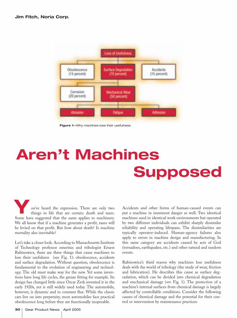
30 Gear Product News April 2005 Gear Product News April 2005 Gear Product News April 2005
ou’ve heard the expression. There are only two things in life that are certain: death and taxes.
Some have suggested that the same applies to machinery. We all know that if a machine generates a profit, taxes will be levied on that profit. But how about death? Is machine mortality also inevitable?
Let’s take a closer look. According to Massachusetts Institute of Technology professor emeritus and tribologist Ernest Rabinowicz, there are three things that cause machines to lose their usefulness (see Fig. 1): obsolescence, accidents and surface degradation. Without question, obsolescence is fundamental to the evolution of engineering and technol-ogy. The old must make way for the new. Yet some inven-tions have long life cycles, the grease fitting for example. Its design has changed little since Oscar Zerk invented it in the early 1920s, yet is still widely used today. The automobile, however, is dynamic and in constant flux. While the classic cars live on into perpetuity, most automobiles face practical obsolescence long before they are functionally inoperable.
Accidents and other forms of human-caused events can put a machine in imminent danger as well. Two identical machines used in identical work environments but operated by two different individuals can exhibit sharply dissimilar reliability and operating lifespans. The dissimilarities are typically operator-induced. Human-agency failures also apply to errors in machine design and manufacturing. In this same category are accidents caused by acts of God (tornadoes, earthquakes, etc.) and other natural and random events.
Rabinowicz’s third reason why machines lose usefulness deals with the world of tribology (the study of wear, friction and lubrication). He describes this cause as surface deg-radation, which can be divided into chemical degradation and mechanical damage (see Fig. 1). The protection of a machine’s internal surfaces from chemical damage is largely affected by controllable conditions. Consider the following causes of chemical damage and the potential for their con-trol or intervention by maintenance practices:
Aren’t Machines Supposed to Wear Out?
Figure 1—Why machines lose their usefulness.Figure 1—Why machines lose their usefulness.Figure 1—
Jim Fitch, Noria Corp.
Y
April 2005 Gear Product News 31 2005 Gear Product News 2005 Gear Product News continued
Jim Fitch is chairman and CEO of Noria Corp. He has a wealth of “in the trenches” experience in lubrication, oil analysis, tribol-ogy and machinery failure investigations. Over the past two decades, he has given hundreds of lectures on these subjects and today is a consultant for dozens of or-ganizations, including Michelin Tire, Timken Bearing, John Deere, Caterpillar, Duke Energy, EPRI, ExxonMobil, International Paper, Cummins Engine, NASA and U.S. Steel.
Fitch is widely published and is editor of Practicing Oil Analysis and Practicing Oil Analysis and Practicing Oil Analysis Machinery Lubrication magazines. He serves as a U.S. Lubrication magazines. He serves as a U.S. Lubricationdelegate to ISO and is convener of the ISO tribology and oil analysis working group. Since 2002, Fitch has been advisory direc-tor and board member of the International Council for Machinery Lubrication (ICML). In 1997, he co-founded Noria Corp.
This article first appeared in the September/October 2002 issue of Machinery LubricationMachinery LubricationMachinery , published by Noria Corp. For more informa-tion, visit www.noria.com
Aren’t Machines Supposed to Wear Out?
• Lubricants with ineffective or distressed barrier-film corrosion inhibitors,• Lubricants prone to rapid oxidation (acid producing),• Crankcase lubricants with impaired alkalinity reserve (acid neutralizing),• Overextended oil change intervals,• Oil contamination by water and/or acids from the work environment,• Uncontrolled growth of biological contamination,• Moist headspace of tanks, sumps and other lubrication compartments,• Exceedingly high operating temperatures,• Improper use of chemically aggressive antiscuff (EP, etc.) additives,• Improper preservation of stored or laid-up equipment or protection from moisture and corrosion agents,• Lubricants that are incompatible with seals, process chemicals, machine metallurgy or surface treatments.
Mechanical surface degradation is subdivided into abra-
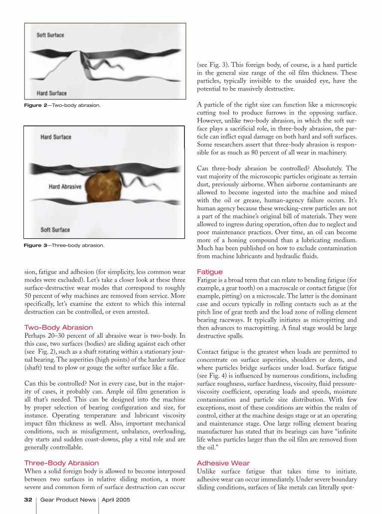
32 Gear Product News April 2005 Gear Product News April 2005 Gear Product News April 2005
Figure 2—Two-body abrasion.
Figure 3—Three-body abrasion.
sion, fatigue and adhesion (for simplicity, less common wear modes were excluded). Let’s take a closer look at these three surface-destructive wear modes that correspond to roughly 50 percent of why machines are removed from service. More specifically, let’s examine the extent to which this internal destruction can be controlled, or even arrested.
Two-Body AbrasionPerhaps 20–30 percent of all abrasive wear is two-body. In this case, two surfaces (bodies) are sliding against each other (see Fig. 2), such as a shaft rotating within a stationary jour-nal bearing. The asperities (high points) of the harder surface (shaft) tend to plow or gouge the softer surface like a file.
Can this be controlled? Not in every case, but in the major-ity of cases, it probably can. Ample oil film generation is all that’s needed. This can be designed into the machine by proper selection of bearing configuration and size, for instance. Operating temperature and lubricant viscosity impact film thickness as well. Also, important mechanical conditions, such as misalignment, unbalance, overloading, dry starts and sudden coast-downs, play a vital role and are generally controllable.
Three-Body AbrasionWhen a solid foreign body is allowed to become interposed between two surfaces in relative sliding motion, a more severe and common form of surface destruction can occur
(see Fig. 3). This foreign body, of course, is a hard particle in the general size range of the oil film thickness. These particles, typically invisible to the unaided eye, have the potential to be massively destructive.
A particle of the right size can function like a microscopic cutting tool to produce furrows in the opposing surface. However, unlike two-body abrasion, in which the soft sur-face plays a sacrificial role, in three-body abrasion, the par-ticle can inflict equal damage on both hard and soft surfaces. Some researchers assert that three-body abrasion is respon-sible for as much as 80 percent of all wear in machinery.
Can three-body abrasion be controlled? Absolutely. The vast majority of the microscopic particles originate as terrain dust, previously airborne. When airborne contaminants are allowed to become ingested into the machine and mixed with the oil or grease, human-agency failure occurs. It’s human agency because these wrecking-crew particles are not a part of the machine’s original bill of materials. They were allowed to ingress during operation, often due to neglect and poor maintenance practices. Over time, an oil can become more of a honing compound than a lubricating medium. Much has been published on how to exclude contamination from machine lubricants and hydraulic fluids.
FatigueFatigue is a broad term that can relate to bending fatigue (for example, a gear tooth) on a macroscale or contact fatigue (for example, pitting) on a microscale. The latter is the dominant case and occurs typically in rolling contacts such as at the pitch line of gear teeth and the load zone of rolling element bearing raceways. It typically initiates as micropitting and then advances to macropitting. A final stage would be large destructive spalls.
Contact fatigue is the greatest when loads are permitted to concentrate on surface asperities, shoulders or dents, and where particles bridge surfaces under load. Surface fatigue (see Fig. 4) is influenced by numerous conditions, including surface roughness, surface hardness, viscosity, fluid pressure-viscosity coefficient, operating loads and speeds, moisture contamination and particle size distribution. With few exceptions, most of these conditions are within the realm of control, either at the machine design stage or at an operating and maintenance stage. One large rolling element bearing manufacturer has stated that its bearings can have “infinite life when particles larger than the oil film are removed from the oil.”
Adhesive WearUnlike surface fatigue that takes time to initiate, adhesive wear can occur immediately. Under severe boundary sliding conditions, surfaces of like metals can literally spot-

April 2005 Gear Product News 33 2005 Gear Product News 2005 Gear Product News
Figure 5—Adhesive wear.
Figure 4—Surface fatigue.
weld together (see Fig. 5). Heavily loaded, slow-moving machines are the most prone to adhesive wear—especially if surfaces slide over a considerable distance, building frictional heat (for example, large meshing gear teeth). Also known as scuffing and galling, adhesive wear may be the least control-lable as compared to contact fatigue and abrasion. More often, it is the extent or rate of wear that is most controllable. When machines are well engineered, well manufactured, properly commissioned and operated within rated loads and speeds, adhesive wear is usually minimal. However, when loads are exceedingly high, there may be a need to deploy surface-active EP/AW additives or solid lubricants (borate, molybdenum disulfide, graphite, etc.).
Machines Don’t Just Die...They’re MurderedFor some machines, trying to stop the progress of wear is like trying to defy gravity. We can’t escape the inevitable. Many machines perhaps are already on life support; they are too far gone. However, this is just for some machines—not all. A high percentage of lubricated machines in normal service can have a seemingly infinite lifespan. They are less prone to wear and failure when well maintained. This is due to the many reasons we’ve just discussed relating to the envi-ronment and operating conditions to which we expose our machine’s surfaces.
You’ve probably heard the word “risk” defined as the prob-ability of failure multiplied by the consequence of failure. When it comes to machine reliability, the consequence of failure may not be within practical control, but the probabil-ity of failure may be.
We’ve talked about the vital impact of human agency on machine reliability. The frequency of human-agency failures tends to run inversely proportional to such factors as training, performance metrics and reliability culture.
Consider this: I recently heard a manager mention that maintenance has two problems:
1. It’s broken because we didn’t work on it.2. It’s broken because we did work on it.
This is the maintenance paradox, no doubt. Anyone in the maintenance field has likely experienced it firsthand. Yet the answer to solving the paradox lies within, by simply restating the two problems as follows:
1. It’s broken because we didn’t know how to prevent it from breaking. Or it’s broken because we didn’t know it was break-ing and therefore didn’t work on it.2. It’s broken because we didn’t know it wasn’t breaking and worked on it anyway. Or it’s broken because we didn’t know how working on it might cause it to break.
“We didn’t know” is the common, operative phrase in the statements above. It, too, is controllable, like wear, but only when initiative is taken to empower maintenance organiza-tions through knowledge. For more on this, refer to my edi-torial on the “Hidden Cost of an Uneducated Workforce” in Practicing Oil Analysis magazine (March-April 2003).Practicing Oil Analysis magazine (March-April 2003).Practicing Oil Analysis
So . . . no, machines aren’t supposed to wear out. Yet they often do, and if you investigate why, you will likely find they were, in fact, murdered. If you follow the root-cause trail, you will likely find a smoking gun in the hands of one or more well-intentioned individuals (operator, craftsman, technician, mechanic, engineer, etc.) who simply didn’t know any better.
Figure 5-1. Figure 5-2.
Figure 5-3. Figure 5-4.

34 Gear Product News April 2005 Gear Product News April 2005 Gear Product News April 2005
This composite image shows how the Magnom fi lter captures debris withoutblocking the flow channels.
ichard Ridgeway faced a serious situation at the Rugeley Power Station in
Staffordshire, England. The station, which runs on coal, depends very heav-ily on 14 gearbox-driven coal pulver-izing mills.
But the gearboxes that power the mills were failing at the rate of four to six times per year, says Ridgeway, tech-nical support engineer for planning at Rugeley.
The gearboxes had been failing because of contaminants in the lubrication sys-tem, which used a filtration system consisting of 2 x 200-micron strainers along with bar magnets. But the sys-tem was not capable of removing fine ferrous contamination.
The pulverizing mills use a high-vis-cosity synthetic oil (BREOX oil—LB460SW) in a recirculating lubri-cation system. Because of the oil’s high viscosity, low-level micron filtration could not be used to remove the contaminants.
One of the options the power station explored was the Magnom™ filtra-tion system. The Magnom is designed to capture submicron-level particles without causing a pressure drop.
Keeping the Oil Clean
R
THE DEVELOPERS OF THE MAGNOM™ MAG-NETIC FILTRATION TECHNOLOGY EXPLAIN HOW THEIR FILTERS ARE HELPING GEARBOX USERS SAVE MONEY.
To Reduce Gearbox Downtime
Keith Day, Magnom

April 2005 Gear Product News 35 2005 Gear Product News 2005 Gear Product News continued
Keeping the Oil Clean
Rugeley installed Magnom technology on a recently refurbished gearbox (see Fig. 1 ), which had been flushed by the rebuilder. All involved expected only very limited contamination, but when Ridgeway removed the core after eight weeks, he was surprised by the amount of debris the Magnom removed from the new fluid (see Fig. 2).
“I was very impressed to see how much debris the Magnom had cap-tured in only a two-month window,” Ridgeway says.
The Magnom engineers were less sur-prised, as this result was very consis-tent with similar power plant applica-tions in the past.
Rugeley Power Station immediately ordered Magnom process units for every coal pulverizing transmission.
Compared with the costs of gear-box failure—roughly $100,000 each to refurbish—not to mention the cost of downtime, the costs of the Magnom system are small. In fact, in cases like the Rugeley power station, the pay-back period can be as little as one to two months.
How it WorksMagnom technology was designed for the Formula 1 and NASCAR racing
To Reduce Gearbox Downtime
Figure 1—Magnom installation at Rugeley Power Station.
Figure 2—The Magnom caputres substantial debris, even after only two months.
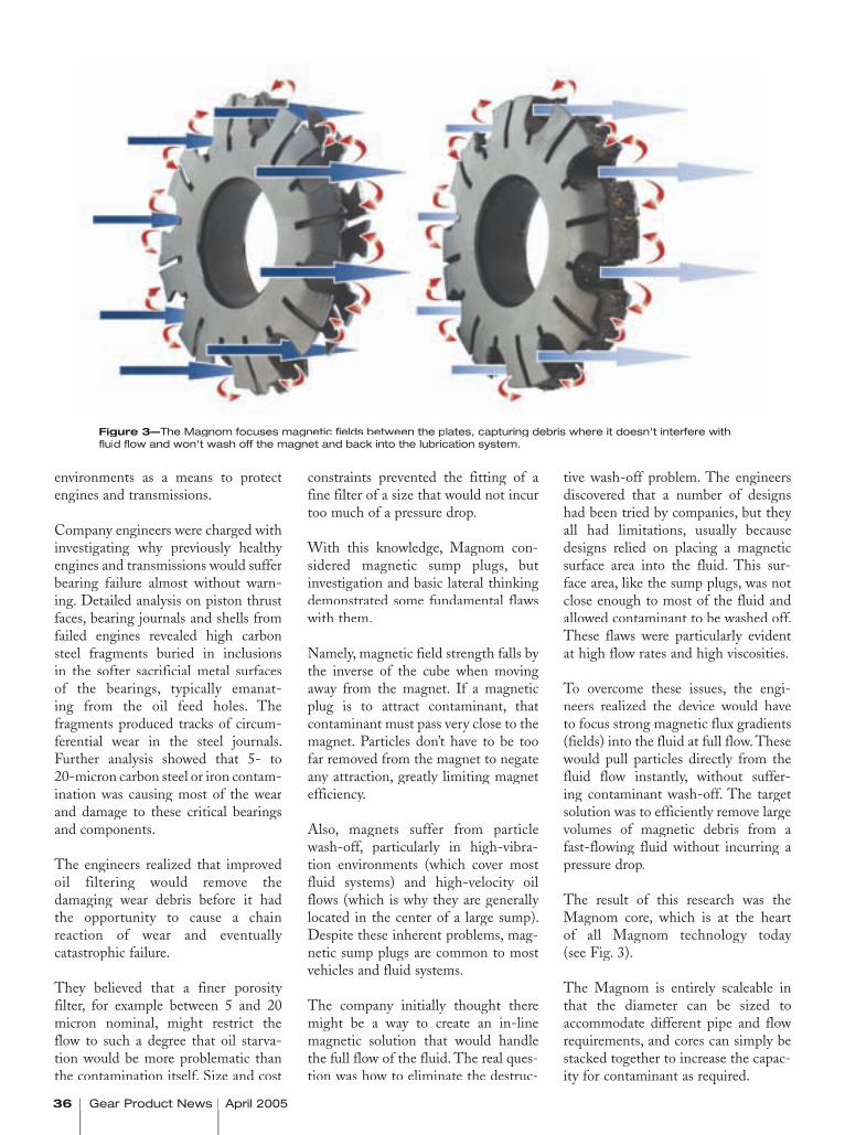
36 Gear Product News April 2005 Gear Product News April 2005 Gear Product News April 2005
tive wash-off problem. The engineers discovered that a number of designs had been tried by companies, but they all had limitations, usually because designs relied on placing a magnetic surface area into the fluid. This sur-face area, like the sump plugs, was not close enough to most of the fluid and allowed contaminant to be washed off. These flaws were particularly evident at high flow rates and high viscosities.
To overcome these issues, the engi-neers realized the device would have to focus strong magnetic flux gradients (fields) into the fluid at full flow. These would pull particles directly from the fluid flow instantly, without suffer-ing contaminant wash-off. The target solution was to efficiently remove large volumes of magnetic debris from a fast-flowing fluid without incurring a pressure drop.
The result of this research was the Magnom core, which is at the heart of all Magnom technology today (see Fig. 3).
The Magnom is entirely scaleable in that the diameter can be sized to accommodate different pipe and flow requirements, and cores can simply be stacked together to increase the capac-ity for contaminant as required.
constraints prevented the fitting of a fine filter of a size that would not incur too much of a pressure drop.
With this knowledge, Magnom con-sidered magnetic sump plugs, but investigation and basic lateral thinking demonstrated some fundamental flaws with them.
Namely, magnetic field strength falls by the inverse of the cube when moving away from the magnet. If a magnetic plug is to attract contaminant, that contaminant must pass very close to the magnet. Particles don’t have to be too far removed from the magnet to negate any attraction, greatly limiting magnet efficiency.
Also, magnets suffer from particle wash-off, particularly in high-vibra-tion environments (which cover most fluid systems) and high-velocity oil flows (which is why they are generally located in the center of a large sump). Despite these inherent problems, mag-netic sump plugs are common to most vehicles and fluid systems.
The company initially thought there might be a way to create an in-line magnetic solution that would handle the full flow of the fluid. The real ques-tion was how to eliminate the destruc-
Figure 3—The Magnom focuses magnetic fi elds between the plates, capturing debris where it doesn't interfere with fl uid fl ow and won't wash off the magnet and back into the lubrication system.
environments as a means to protect engines and transmissions.
Company engineers were charged with investigating why previously healthy engines and transmissions would suffer bearing failure almost without warn-ing. Detailed analysis on piston thrust faces, bearing journals and shells from failed engines revealed high carbon steel fragments buried in inclusions in the softer sacrificial metal surfaces of the bearings, typically emanat-ing from the oil feed holes. The fragments produced tracks of circum-ferential wear in the steel journals. Further analysis showed that 5- to 20-micron carbon steel or iron contam-ination was causing most of the wear and damage to these critical bearings and components.
The engineers realized that improved oil filtering would remove the damaging wear debris before it had the opportunity to cause a chain reaction of wear and eventually catastrophic failure.
They believed that a finer porosity filter, for example between 5 and 20 micron nominal, might restrict the flow to such a degree that oil starva-tion would be more problematic than the contamination itself. Size and cost

April 2005 Gear Product News 37 2005 Gear Product News 2005 Gear Product News
Generally, the Magnom’s flow channels tend to combine to a flow area equal to more than 110 percent of the feed pipe flow area. In this way, the pressure drop across the Magnom starts low and remains low even when it collects large amounts of contamination.
Given this low backpressure design, the Magnom can be fitted on the suction side of a pump without fear of creating cavitations due to a pres-sure drop. In many full-flow systems, the pump is often the most expensive component and is devoid of effective filtration protection.
The Magnom has demonstrated removal of contaminant that is less than one micron in size (0.07 microns to be exact).
The technology has been scaled to a number of different applications, including large scale transmissions.
The Magnom in ActionIn addition to Rugeley, the Magnomhas been used at a number of other power stations in England.
The first Magnom power plant instal-lation was at the Didcot A Power Station in Oxfordshire, England. Conventional filtration could not be
used because it caused too much of a pressure drop, placing a huge strain on the pump.
The Magnom was used by Didcot to clean the open gear lubricant on a coal pulverizing gearbox after it had seen significant gear wear.
The Magnom process unit was used, as it could be installed into a 2" line without increasing the pressure drop. The unit was also appropriate because it is capable of removing up to 4 kg of contaminant before it is cleaned.
As the lubrication system was not recirculatory in nature, the filter was skid-mounted with a small pump, as shown in Figure 4.
The Magnom’s design allows simple inspection. The unit was therefore examined after only two weeks. Large amounts of magnetic and non-mag-netic debris had been captured.
An oil analysis showed that once the process unit was installed, con-tamination levels were reduced to acceptable levels.
Contaminants removed by the filter at Didcot have included iron, soot, alu-minum and copper contaminants. The
advantages of running much cleaner lubricant include increased gearbox life, increased fluid life and improved gearbox efficiency.
The Didcot A Power Station has since retrofitted Magnom process units to each of its 32 coal pulverizing transmissions.
After the initial clean-up of the system with the Magnom, the core has to be cleaned only every four years as part of planned outages. Figure 5 shows a Magnom core only ¼ full. This core was photographed 12 months after the initial lubricant clean-up had been completed.
Since adopting the Magnom technol-ogy across the entire Didcot A plant, gearbox failure rates dropped from an average of four per year down to zero per year, and the payback period has been less than three months.
Another example of the filter’s use in power generation is at the Drax Coal Fired Power Station in North Yorkshire, England. Drax uses recircu-lating lubricant on its coal pulverizing transmissions.
Engineers at Drax quickly found the contamination removal to be successful
continued
Figure 4—Magnom installation at the Didcot A Power Station in England.
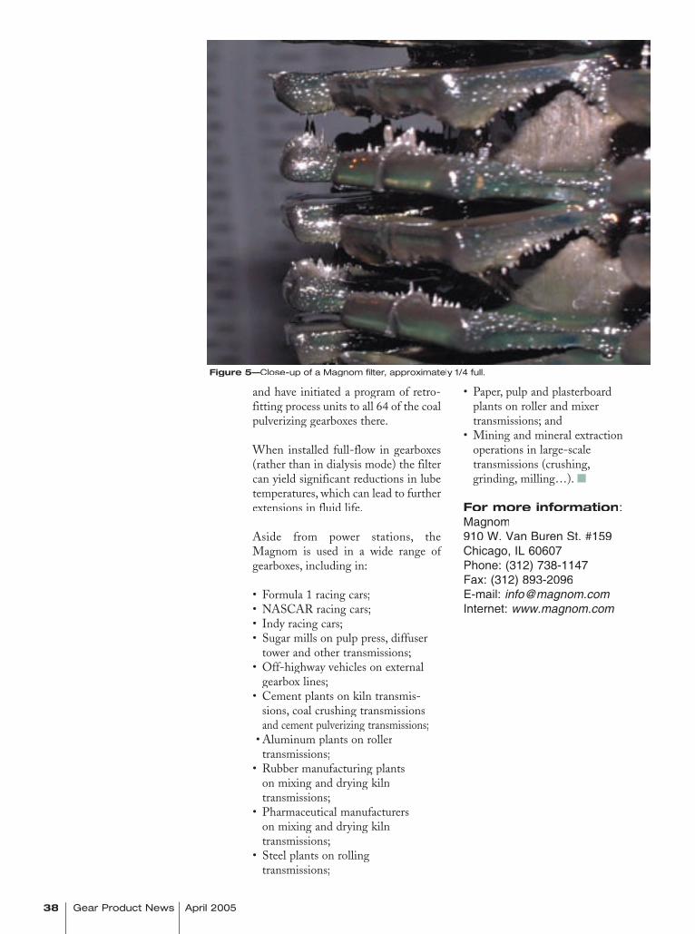
• Paper, pulp and plasterboard plants on roller and mixer transmissions; and • Mining and mineral extraction operations in large-scale transmissions (crushing, grinding, milling…).
For more information:Magnom910 W. Van Buren St. #159Chicago, IL 60607Phone: (312) 738-1147Fax: (312) 893-2096E-mail: [email protected]: www.magnom.com
Figure 5—Close-up of a Magnom fi lter, approximately 1/4 full.
38 Gear Product News April 2005 Gear Product News April 2005 Gear Product News April 2005
and have initiated a program of retro-fitting process units to all 64 of the coal pulverizing gearboxes there.
When installed full-flow in gearboxes (rather than in dialysis mode) the filter can yield significant reductions in lube temperatures, which can lead to further extensions in fluid life.
Aside from power stations, the Magnom is used in a wide range of gearboxes, including in:
• Formula 1 racing cars;• NASCAR racing cars;• Indy racing cars;• Sugar mills on pulp press, diffuser tower and other transmissions; • Off-highway vehicles on external gearbox lines;• Cement plants on kiln transmis- sions, coal crushing transmissions
and cement pulverizing transmissions;• Aluminum plants on roller
transmissions;• Rubber manufacturing plants on mixing and drying kiln transmissions; • Pharmaceutical manufacturers on mixing and drying kiln transmissions; • Steel plants on rolling transmissions;
See our Complete Inventory with Photos at: www.cadillacmachinery.com
WE BUY & SELLGEAR EQUIPMENT
.

40 Gear Product News April 2005 Gear Product News April 2005 Gear Product News April 2005
case study
hen it was time for Remy Inc. of Anderson, IN, to replace older gear inspection equipment, at the top of
the company’s list of requirements was a system that would be easy to set up, easy to use and easy to change over.
Remy manufactures the Delco-Remy brand of alternators and Remy manufactures the Delco-Remy brand of alternators and Remy manufactures the Delco-Remystarters for the worldwide heavy-duty truck, agricultural, con-struction and industrial markets. The Anderson location does research and development work for those components, and therefore, the metallurgical lab sees a lot of variety in parts, says inspection machine lab technician Stephen Fernung.
“Before, it seemed to be a big deal to enter param-eters and perform part changeovers,” Fernung says. The previous gear inspection equipment at Remy was built in the 1980s and didn’t have all the features or updated software of today’s inspection systems.
Remy purchased a new ND430 Next Dimension analytical gear inspection system from Process Equipment Co. of Tipp City, OH. The ND430 is a Windows-based, four-axis generative elemental gear measurement system that utilizes a Renishaw3-D scanning probe for measuring index, helix and involute profile deviations on gears.
“Out of all the systems we evaluated, we found the ND430 Next Dimension Gear Measurement system to be the easiest system to operate,” Fernung says. “If you knew how to operate Windows, this was an easy machine to learn.”
The machine’s ease of use was extremely important because of the variety of parts that the R&D lab sees, Fernung says. “The probe calibration and changeover was a lot easier for us as opposed to the machine we had before.”
Also, Fernung says, the ND430 has a lot of features that were important in the company’s decision-making: “We have used other analytical equipment in the past, but have not found any-thing that has all of the attributes that the Next Dimension has.”
PROCESS EQUIPMENT COMPANY
HELPS REMY STREAMLINE PART INSPECTION
W
Among those important attributes are the ND430’s ability to automatically center a part and its built-in off-axis correction, Fernung says.
Another important feature for Remy—a company with manufacturing locations around the globe—is the ability to analyze parts using DIN, ISO, AGMA or user-defi ned standards and the ability to switch between standards with just a keystroke.
Earlier this year, Remy purchased its second ND430 system. According to Fernung, the technical support provided by Process Equipment was “a major reason” for selecting the vendor a second time.
“The service they gave us was a huge selling point,” Fernung says. “They were really willing to work with us.” Process Equipment modified the software so that the analysis results were easy to understand for Remy’s engineers. “They made the printouts and results look similar to what we had previously.”
According to Process Equipment’s business unit manager, Brian Slone, the company’s approach is always to work with the customer to make sure the system is right for him. “It’s very easy for us to customize the analysis packages,” Slone says.
For more information:Metrology Systems DivisionProcess Equipment Co.4191 U.S. Route 40Tipp City, OH 45371Phone: (937) 667-7105Fax: (937) 667-2591E-mail: [email protected]: www.gearinspection.com
April 2005 Gear Product News 41 April 2005 Gear Product News April 2005 Gear Product News
WE BUY GEAR MACHINES Gear Hobbers, Shapers, Grinders, Sharpeners, Shavers,
Any Gleason Equipment, and Spline Rollers.
WANT TO FREE UP SHELF SPACE? WE WANT TO BUY YOUR GLEASON INDEX PLATES, CONIFLEX AND
HYPOID CUTTER BODIES, CAMS, GEARS, AND SPARE PARTS, SURPLUS TOOLING, EQUIPMENT AND
GEARS FOR ANY GEAR MACHINERY.E-mail or fax us
a list of your surplus, with photos.Ph: 847-437-6600 Fax: 847-437-6618
E-mail: [email protected]
CADILLAC MACHINERY CO., INC. 1401 Lunt Ave., Elk Grove Village, IL 60007 USA

nited Gear & Assembly Inc. (UGA) of Hudson, WI, was running at or near full capacity in a
number of manufacturing cells, but demand for its engine timing and transmission gears was on the rise. The company needed a way to increase manufacturing capacity.
For the past year, UGA has been converting those manu-facturing cells from traditional hobbing with cutting fluid to dry hobbing cells, resulting in substantially decreased cycle times.
“The main reason we do it is to improve our through-put,” says Markus Bieber, director of sales and marketing. “Dry hobbing allows us to cut our cycle time roughly in half, so it basically allows us to double the throughput on each machine.”
UGA uses Mitsubishi GE15A and GE20A hobbing machines. For some of its manufacturing cells, the company purchased new equipment. In other cases, it didn’t have to. “We were able to take some of our Mitsubishi hobbers and convert those from wet hobbing to dry hobbing,” Bieber says.
42 Gear Product News April 2005 Gear Product News April 2005 Gear Product News April 2005
case study
United Gear & Assembly INCREASES CAPACITY THROUGH DRY HOBBING
In the past year, UGA has completed the conversion to dry hobbing on about a dozen manufacturing cells.
Cutting tools for dry hobbing are more expensive than the cutting tools UGA used previously, Bieber says, because of the different coatings required on them. “But it’s not as much as you would think.” The hobs being used in the dry cutting cells are about 15% more expensive than the old hobs, Bieber says. But that additional cost is outweighed by the additional productivity the company is able to achieve.
Some of the costs associated with the tooling are also off-set in other areas. By eliminating cutting fluids, there are reduced costs in areas such as parts washing and facility maintenance.
Changing to dry hobbing has required relatively little change on the part of the company, Bieber says. No retraining of employees was necessary. Moreover, the dry manufacturing cells have been extremely well received by the company’s shop floor employees.
“These are some of the sought-after cells,” Bieber says. “Everybody wants to be moved to those cells.”
The reason the dry cells are so popular is because, without cutting fluids, the operation is much simpler now, Bieber says. “When you’ve got a hobbing operation, the operator generally has to take the part out and blow the oil off the part before he puts it into the next operation. That’s eliminated with dry hobbing.”
Also, with dry hobbing, most of the heat generated by cut-ting the part is carried away with the chips, so the parts can be handled immediately after cutting, Bieber says.
Removing cutting fluids from the operation can have health and safety benefits. “Sometimes employees have reactions to the cutting fluids. You’re taking that out of the equation,” Bieber says.
U
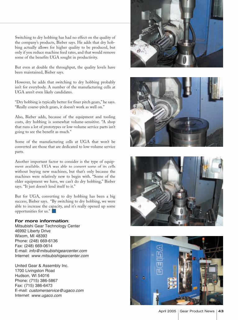
April 2005 Gear Product News 43 April 2005 Gear Product News April 2005 Gear Product News
Switching to dry hobbing has had no effect on the quality of the company’s products, Bieber says. He adds that dry hob-bing actually allows for higher quality to be produced, but only if you reduce machine feed rates, and that would remove some of the benefits UGA sought in productivity.
But even at double the throughput, the quality levels have been maintained, Bieber says.
However, he adds that switching to dry hobbing probably isn’t for everybody. A number of the manufacturing cells at UGA aren’t even likely candidates.
“Dry hobbing is typically better for finer pitch gears,” he says. “Really coarse-pitch gears, it doesn’t work as well on.”
Also, Bieber adds, because of the equipment and tooling costs, dry hobbing is somewhat volume-sensitive. “A shop that runs a lot of prototypes or low-volume service parts isn’t going to see the benefit as much.”
Some of the manufacturing cells at UGA that won’t be converted are those that are dedicated to low-volume service parts.
Another important factor to consider is the type of equip-ment available. UGA was able to convert some of its cells without buying new machines, but that’s only because the machines were relatively new to begin with. “Some of the older equipment we have, we can’t do dry hobbing,” Bieber says. “It just doesn’t lend itself to it.”
But for UGA, converting to dry hobbing has been a big success, Bieber says. “By switching to dry hobbing, we were able to increase the capacity, and it’s really opened up some opportunities for us.”
For more information:Mitsubishi Gear Technology Center46992 Liberty DriveWixom, MI 48393Phone: (248) 669-6136Fax: (248) 669-0614E-mail: [email protected]: www.mitsubishigearcenter.com
United Gear & Assembly Inc.1700 Livingston RoadHudson, WI 54016Phone: (715) 386-5867Fax: (715) 386-6473E-mail: [email protected]: www.ugaco.com
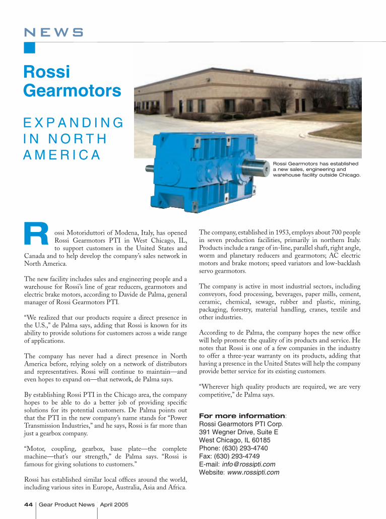
44 Gear Product News April 2005Gear Product News April 2005
news
ossi Motoriduttori of Modena, Italy, has opened Rossi Gearmotors PTI in West Chicago, IL, to support customers in the United States and
Canada and to help develop the company’s sales network in North America.
The new facility includes sales and engineering people and a warehouse for Rossi’s line of gear reducers, gearmotors and electric brake motors, according to Davide de Palma, general manager of Rossi Gearmotors PTI.
“We realized that our products require a direct presence in the U.S.,” de Palma says, adding that Rossi is known for its ability to provide solutions for customers across a wide range of applications.
The company has never had a direct presence in North America before, relying solely on a network of distributors and representatives. Rossi will continue to maintain—and even hopes to expand on—that network, de Palma says.
By establishing Rossi PTI in the Chicago area, the company hopes to be able to do a better job of providing specifi c solutions for its potential customers. De Palma points out that the PTI in the new company’s name stands for “Power Transmission Industries,” and he says, Rossi is far more than just a gearbox company.
“Motor, coupling, gearbox, base plate—the complete machine—that’s our strength,” de Palma says. “Rossi is famous for giving solutions to customers.”
Rossi has established similar local offi ces around the world, including various sites in Europe, Australia, Asia and Africa.
The company, established in 1953, employs about 700 people in seven production facilities, primarily in northern Italy. Products include a range of in-line, parallel shaft, right angle, worm and planetary reducers and gearmotors; AC electric motors and brake motors; speed variators and low-backlash servo gearmotors.
The company is active in most industrial sectors, including conveyors, food processing, beverages, paper mills, cement, ceramic, chemical, sewage, rubber and plastic, mining, packaging, forestry, material handling, cranes, textile and other industries.
According to de Palma, the company hopes the new offi ce will help promote the quality of its products and service. He notes that Rossi is one of a few companies in the industry to offer a three-year warranty on its products, adding that having a presence in the United States will help the company provide better service for its existing customers.
“Wherever high quality products are required, we are very competitive,” de Palma says.
For more information:Rossi Gearmotors PTI Corp.391 Wegner Drive, Suite EWest Chicago, IL 60185Phone: (630) 293-4740Fax: (630) 293-4749E-mail: [email protected]: www.rossipti.com
RossiGearmotors
E X P A N D I N G I N N O R T H A M E R I C A
R
Rossi Gearmotors has established a new sales, engineering and warehouse facility outside Chicago.
April 2005 Gear Product News 45
news
Griffi n Gear A d o p t s E S O PGriffin Gear Inc., located in Spartanburg, SC, has adopt-ed an employee stock ownership plan for the benefit of its employees.
“We thoroughly and conscientiously studied what were the best alternatives for our company to operate in the 21st
century,” says president Joe Griffin Jr. “We determined that for the company, the shareholders and our employees, the ESOP alternative was our best choice and was a ‘win-win’ for all. We are excited and poised to be working as an employee-owned company.”
Griffin Gear manufactures replacement gears for all indus-tries with gears up to 20 feet in diameter.
AGMA I n d u c t s N e w O f f i c e r sAt the AGMA annual meeting held in March, the associa-tion announced new officers for 2005. The new officers are:
• Chairman, Leslie Hennessy of Lovejoy Inc.• Vice-Chairman, Stan Blenke of Schafer Gear
Works Inc.• Treasurer, Rick Fullington of Milwaukee Gear Co.• Chairman, Business Management Executive
Committee, Dennis Gimpert of Koepfer America LLC
• Chairman, Technical Division Executive Committee, Edward Lawson of M&M Precision Systems Corp.
• Chairman Emeritus, Fred Sowinski of Falk Corp.
In addition, the association’s lifetime achievement award was presented to Martin Woodhouse, who is VP of sales for Star Cutter Co.
We have 50,000 square feet with literally hundreds of all types of modern gear equipment. See our website for a complete inventory of our gear machine tools, most with
photos, and an individual inventory of our gear tooling and accessories.
Fax or E-mail your requirements:Ph: 847-437-6600 Fax: 847-437-6618
FLYING INTO CHICAGO?VISIT US NEXT TO O’HARE AIRPORT
Visiting on business? Attending an auction?First or last — visit Cadillac Machinery
CADILLAC MACHINERY CO., INC. 1401 Lunt Ave., Elk Grove Village, IL 60007 USA
GEAR TECHNOLOGYThe Journal of Gear Manufacturing
Rand
all P
ublis
hing
, Inc
., 14
25 L
unt A
venu
e, E
lk G
rove
Vill
age,
IL 6
0007
Fax
you
r for
m to
(847
) 437
-661
8 or
vis
it us
at w
ww
.gea
rpro
duct
new
s.co
m o
r ww
w.g
eart
echn
olog
y.co
m
1. What is the principal product manufactured or service performed at THIS LOCATION?_______________________________________________________
2. How is THIS LOCATION involved in the gear industry? (Check all that apply) WE MAKE GEARS AND SELL THEM-Gear Job Shop (20,3) WE MAKE GEARS AND USE THEM IN OUR PRODUCTS-Captive Gear Shop (20,2) WE BUY GEARS (22) We make gear manufacturing machines (7) We distribute NEW gear manufacturing machines (including agents and sales reps) (8) We make gear tooling & accessories (14) We distribute NEW gear tooling & accessories (including agents and sales reps) (12) We distribute gears or gear products (including agents and sales reps) (26) We design gears (32) We are a used machinery dealer or rebuilder (11) We provide a service to the gear industry (31) (please describe)_______________________________________________ Other (please describe)___________________________________________
3. Which of the following processes does THIS LOCATION use to make gears? (Check all that apply) Gear/Spline Hobbing (40) Gear Finishing & Cleaning (36) Gear Shaving (38) Bevel Gear Generating (43) Gear Broaching (30) Gear Grinding (35) Gear Forging (34)
4. How many employees are at THIS LOCATION? (Check ONE) 1-19 20-49 50-99 100-499 500+
5. What is your primary functional responsibility? (Check ONE) Corporate Management (1) Manufacturing Production (2) Manufacturing Engineering (3) Marketing & Sales (4)
*Please note: Company info above must be included to qualify for a FREE subscription.
IN ORDER TO QUALIFY FOR (OR RENEW) A FREE SUBSCRIPTION, YOU MUST ANSWER ALL THE QUESTIONS BELOW.
Name:_______________________________________________________ Title:__________________________________________________________
Company Name:_______________________________________________ E-mail:__________________________________________________________
Company Address:_____________________________________________ Parent Co. Name: ________________________________________________
City:_________________________________________________________ State:________________________________ ZIP:______________________
Telephone:______________________________ Fax:__________________ Internet Address:_______________________________________________
Product Design/R&D (5) Purchasing (6) Quality Control (7)Other (please describe)_____________________________________
Gear Deburring (33) Gear Shaping (37) Gear Tool Sharpening (48) Gear Tool Coating (49) Other Gear Mfg._________________________________________ NO GEAR MANUFACTURING AT THIS LOCATION
Gear Inspection (31) Plastic Injection Molding of Gears (44) Gear/Spline Rolling (46) Powder Metal Gear Mfg. (45) Gear Chamfering (42) Gear Heat Treating (39) Gear Blank Manufacturing (47)
____YES, I would like to receive Gear Product News ____ NO Signature_____________________________________ Title_________________________
I would like to receive the ____ print version ____ electronic E-GPN ____ both (need e-mail address)___________________________________
THERE’S ONLY ONE WAY...to learn about the products, companies and people of the gear industry.To learn about our technical field without all the technical depth...Sign uptoday to receive your FREE subscription to Gear Product News magazine.It's the perfect complement to Gear Technology.
P R O D U C T
www.gearproductnews.com
THERE’S ONLY ONE WAY...to have the most in-depth information available on gear design, manufacturing, processing, buying and use...Sign up today to receive your FREE subscription to Gear Technology magazine. Our flagship publication in print for 20 years.
____YES, I would like to receive Gear Technology Technology Technology ____ NO Signature_____________________________________ Title_________________________
I would like to receive the ____ print version ____ electronic E-GT ____ both (need e-mail address)_____________________________________
I prefer home delivery/Company requires home delivery. Home address is: *Please note: Company info above must be included to qualify for a FREE subscription.
Address :____________________________________________________________________________________________________________________________________________________
City :______________________________________________________________________State :__________________________Zip :_______________________________
YES, you may send me faxes to the number listed above. YES, you may send me e-mail to the address listed above. NO, I do not wish to be contacted by fax or e-mail.
SEND YOUR COMPLETE SUBSCRIPTION FORM TO
P.O. BOX 1426, ELK GROVE VILLAGE, IL 60007 OR FAX TO (847) 437-6618

classifieds
April 2005 Gear Product News 47
He
lp W
an
ted
He
at
Tre
ati
ng
Se
rvic
e
Bevel GearsBull GearsChain GearsDryer GearsHerringbonesHelical GearsInternal GearsKiln Gears
Miter GearsPinionsRacksRing GearsSprocketsSpur GearsWorm Gears
We also rebuild pumps, shafts, rolls, compressor blowers, stone crushing combs, rolls for grinding, rings, hammers and all other types of machinery.
UNITED MACHINE & GRINDING6210 Long Drive
Houston, TX 77087Phone: (713) 686-1200
WE REPAIR BROKEN OR
WORN OUT GEARSBroken teeth—worn out, chipped orcracked—we rebuild them back up totheir original size and get your gearboxback up and running like new.
GEARBOX REPAIR, ALL MAKES ANDMODELS, HIGH & LOW SPEED:
We’ll work with your cast steel, cast iron,bronze, steel, or brass gears.
UNITED MACHINE & GRINDING
UMG
WE’RE HIRING— Two Positions Available —
Gleason Expert —Mechanical troubleshooting of various Gleason equipment. Experience in electronics. Engineering background. Gear Machine Repairman —Experienced troubleshooter for mechanical and hydraulic repairs. Knowledge of electrical systems desirable. No travel.
Friendly work environment at our convenient northwest suburban Chicago location.Profit sharing, health insurance.
CADILLAC MACHINERY CO. INC.1401 Lunt Avenue, Elk Grove Village, IL 60007
E-mail: [email protected] your resume to 847-437-6618
�
310 Innovation Drive • Blairsville, PA 15717
Quality rebuild services and replacements for all types of gearboxes including:
• Parallel shaft• Right angle • Inline Concentric • Shaft Mount• Worm Drives
For more information, please contact us at:
Gearbox Repair Division
Phone: 724/459-0302 x310Fax: 724/459-0305e-mail: [email protected]
He
at
Tre
ati
ng
Induction Hardening Specialists in Tooth by Tooth Contour
Hardening of InternalSpur, helical and bevel gears
Our gear hardening equipment includes 5NATCO submerged process machines and 5AJAX CNC-controlled gear scanningmachines. Tooth by tooth gear hardeningfrom .5DP-10DP, up to 15 tons, 200" diameter.
American Metal Treating CompanyCleveland, Ohio
Phone: (216) 431-4492 • Fax: (216) 431-1508Web: www.americanmetaltreating.com
E-mail: [email protected]
BreakdownServiceAvailable
P R O D U C T
www.gearproductnews.com
48 Gear Product News April 2005 Gear Product News April 2005 Gear Product News April 2005
advertiser index
RATES:BLACK-AND-WHITE BLACK-AND-WHITE BLACK-AND-WHITE 6X 6X 6X 3X 3X 3X 1XFull Page $1,795 $1,925 $1,985Two-Thirds Page $1,320 $1,365 $1,395Half-Page Island $1,050 $1,115 $1,160Half-Page $995 $1,080 $1,115One-Third Page $680 $725 $760One-Quarter Page $540 $560 $600Classified (1/9 Page) $220 $260 $280
COLOR COLOR COLOR 6X 6X 6X 3X 3X 3X 1XFull Page $2,250 $2,385 $2,485Two-Thirds Page $1,650 $1,725 $1,750Half-Page Island $1,325 $1,395 $1,450Half-Page $1,250 $1,350 $1,395One-Third Page $850 $900 $950One-Quarter Page $675 $700 $750Classified (1/9 Page) $275 $325 $350
Place an ad in Gear Product News to reach executives, purchasing agents,
tooling buyers and other decision-makers in the
North American gear industry.
Join This List of Advertisers
DEADLINES:ISSUE AD MUST MATERIALS
BE PLACED DUEJune 2005 May 2 May 9August 2005 July 1 July 8October 2005 September 1 September 8December 2005 November 1 November 8
CONTACT:Daniel Pels, Business Development ManagerRandall Publishing, Inc.1425 Lunt Ave.Elk Grove Village, IL 60007 USAPhone: (847) 437-6604Fax: (847) 437-6618E-mail: [email protected]
American Metal Treating Co.Page 47(216) 431-4492bruce@americanmetaltreating.comwww.americanmetaltreating.com
A/W Systems Co.Back Cover(248) 544-3852
Cadillac Machinery Co. Inc.Pages 39, 41, 45, 47(847) [email protected]
Clifford-Jacobs Forging Co.Page 41(217) [email protected]
Comtorgage Corp.Page 11(401) [email protected]
Forest City Gear Inside Back Cover, Page 15(815) 623-2168www.fcgear.com
Gleason Corp.Inside Front Cover(585) [email protected]
Grupo CEAPage 13(512) [email protected]@sbcglobal.netafgear@sbcg
Ikona Gear InternationalPage 15(604) 523-5500www.ikonagear.com
Kapp TechnologiesPage 3(303) [email protected]
Midwest Gear & Tool Inc.Page 9(586) [email protected]
Penn Machine Co.Page 47(724) [email protected]
Presrite Corp.Pages 7, 15(216) 441-5990www.presrite.com
Quality Transmission ComponentsPage 45(516) 437-6700www.qtcgears.com
Sigma PoolPage 4(734) [email protected]
United Machine & GrindingPage 47(713) 686-1200
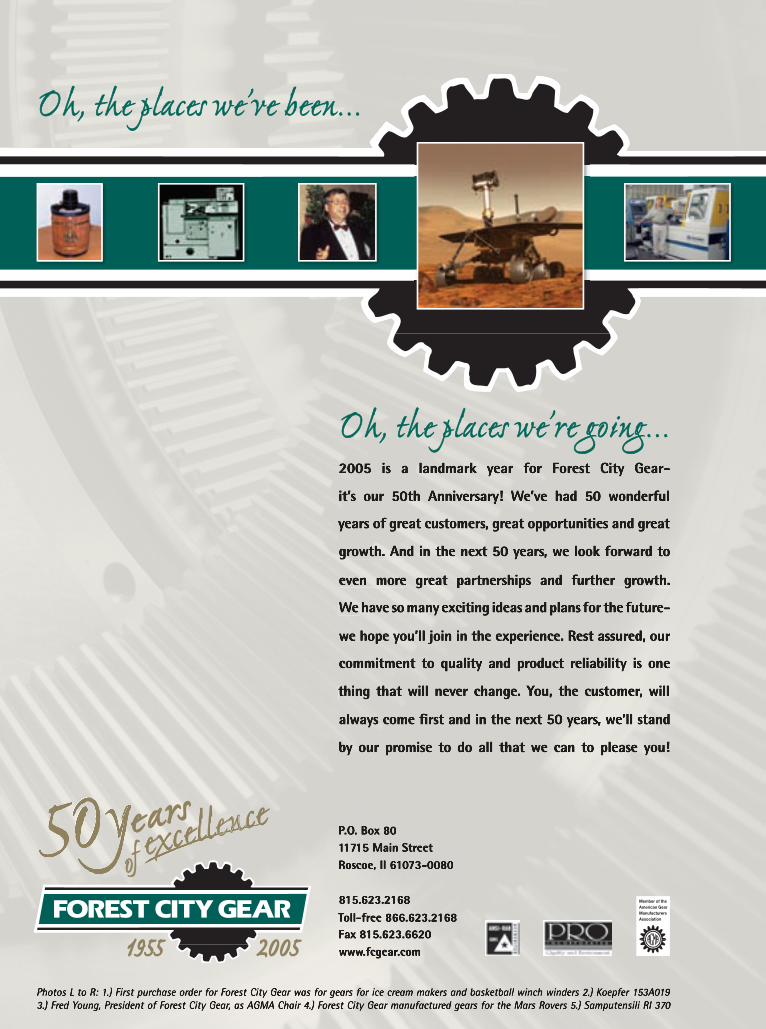
���������������������������������� ��� �� ��������� ����� ���� ������� ����� �����������������������
����� ���� ����� ������������� ������ ���� ��� ����������
��������������������������������������������������������
�����������������������������������������������������
����� ����� ������ ������������� ���� �������� ��������
��������������������������������������������������������
���������������������������������������������������������
����������� ��� �������� ������������ ������������ ��� ����
������ ����������������������������� �������������������
�������������������������������������������������������
��������������� ���������� �������� ���� ���������� ����
�������������������������������������������������������������������������������������������������������������������������������������������������������������������������������������������������������������������������������������������������������������������������������������������������
��������������������������������������������������
�����������������������������������������������������������������
����������������������������
Quality Spiral Bevel Tools
A/W Systems Co. is your quality alternative manufacturing source of spiral gear roughing and finishing cutters and bodies.We can also manufacture new spiral cutter bodies in diameters of 5" through 12" at present.
A/W can also supply roughing and finishing cutters for most 5"–12" diameter bodies.Whether it’s service or manufacturing, consider us as an alternative source for cutters and bodies.
You’ll be in for a pleasant surprise.
Royal Oak, MI 48067 Tel: (248) 544-3852 • Fax: (248) 544-3922
Page 8 12/17/04 4:33 PM Page 8