Magnitude Magnetic Bearing Centrifugal...
64
Operation & Maintenance Manual OMM 1034-4 Group: Chiller Part Number: 331499501 Effective: November 2012 Supersedes: July 2012 Magnitude Magnetic Bearing Centrifugal Chillers Model WME 0500 - 700 Software Version: 4.33.1
Transcript of Magnitude Magnetic Bearing Centrifugal...

Operation & Maintenance Manual OMM 1034-4
Group: Chiller Part Number: 331499501
Effective: November 2012
Supersedes: July 2012
Magnitude Magnetic Bearing Centrifugal Chillers
Model WME 0500 - 700
Software Version: 4.33.1

2 OMM 1034-4
Table of Contents Introduction ................................................3
Features of the Control Panel ...................8
General Description ...................................9
Component Description ...........................10Operator Interface Touch Screen .........................10 Unit Controller .....................................................10 Motor/Compressor Controller .............................. 11 VFD Controller .................................................... 11 VFD Description: ................................................. 11 Key VFD Control Signals ....................................12 Inputs and Outputs ...............................................12
Optional Harmonic Filters ......................15
Field Wiring Data .....................................16
Operator Interface Touch Screen (OITS)19Navigation ............................................................19 SET Screens .........................................................25 Service Screens ....................................................40 Downloading Data ...............................................41 Chiller Alarms ......................................................42 Trend Screens .......................................................46
Operating the Chiller .............................. 47Interface Panel On/Off ........................................ 47 Start/Stop Unit ..................................................... 47 Changing Setpoints ............................................. 47
Sequence of Operation ............................ 47
Troubleshooting ....................................... 49Operation with Failed OITS ................................ 50
Maintenance............................................. 51External Sensors and Valve Locations ................ 51 Routine Maintenance........................................... 54 Annual Shutdown ................................................ 57 Annual Startup .................................................... 57 Repair of System ................................................. 57
Maintenance Schedule ............................ 60
Service Programs ..................................... 61
Operator Training ................................... 61
Warranty Statement ................................ 61
Recognize Safety Symbols, Words, and Labels The following symbols and labels indicate immediate or potential hazards. Read and comply with all safety information and instructions accompanying these symbols. Failure to heed safety information increases the risk of property and/or product damage, serious injury or death. Improper installation, operation and maintenance can void the warranty.
CAUTION
Cautions indicate potentially hazardous situations, which can result in personal injury or equipment damage if not avoided.
WARNING
Warnings indicate potentially hazardous situations, which can result in property damage, personal injury, or death if not avoided.
DANGER Dangers indicate a hazardous situation which will result in death or serious injury if not avoided.
© 2013 Daikin Applied. Illustrations and data cover the Daikin product at the time of publication and we reserve the right to make changes in design and construction at anytime without notice. ™® The following are trademarks or registered trademarks of their respective companies: BACnet from ASHRAE; LONMARK, LonTalk, LONWORKS, and the LONMARK logo are managed, granted and used by LONMARK International under a license granted by Echelon Corporation; Modbus from Schneider Electric; Victaulic from Victaulic Company; Magnitude, Energy Analyze, MicroTech E, Open Choices from Daikin.

OMM 1034-4 3
Introduction This manual provides operating, maintenance and troubleshooting information for the Daikin Magnitude frictionless centrifugal chiller with magnetic bearing compressor, Model WME, with MicroTech® E control.
! WARNINGElectric shock hazard. Can cause personal injury or equipment damage. This equipment must be properly grounded. Connections to
and service of the MicroTech control panel must be performed only by personnel that are knowledgeable in the operation of the equipment being controlled.
! CAUTIONStatic sensitive components. A static discharge while handling electronic circuit boards can damage components. Discharge any static electrical charge by touching the bare metal inside the control panel before performing any service work. Never unplug any cables, circuit board terminal blocks, or power plugs while power is applied to the panel.
! CAUTIONDo not install any software not authorized by Daikin or alter operating systems in any unit microprocessor, including the interface panel. Doing so can cause malfunction of the control system and possible equipment damage.
NOTICE This equipment generates, uses, and can radiate radio frequency energy and, if not installed and used in accordance with this instruction manual, may cause interference to radio communications. Operation of this equipment in a residential area is likely to cause interference in which case the user will be required to correct the interference at their expense. Daikin disclaims any liability resulting from any interference or for the correction thereof.
Equipment Location WME chillers are intended only for installation in an indoor or weather protected area consistent with the NEMA 1 rating on the chiller, controls, and electrical panels. Equipment room temperature for operating and standby conditions is 40°F to 104°F (4.4°C to 40°C).
4 OMM 1034-4
Optimum Water Temperatures and Flow A key to improving energy efficiency for any chiller is minimizing the compressor pressure lift. Reducing the lift reduces the compressor work and its energy consumption per unit of output. The chiller typically consumes more energy than any other component in the chiller system. Therefore, the optimum plant design must take into account all of the interactions between chiller, pumps, and tower.
Higher Leaving Chilled Water Temperatures Warmer leaving chilled water temperatures will raise the compressor's suction pressure and decrease the lift, improving efficiency. Using 45°F (7°C) leaving water instead of 42°F (5.5°C) will significantly reduce chiller energy consumption.
Evaporator Temperature Drop The industry standard has been a 10°F (5.5°C) temperature drop in the evaporator. Increasing the drop to 12°F or 14°F (6.6°C or 7.7°C) can improve chiller efficiency. Chilled water pump energy will also be reduced.
Reduced Evaporator Fluid Flow Several popular chiller plant control practices including Variable Primary Flow systems advocate reducing the evaporator fluid flow rate as the chiller capacity is reduced. This practice can significantly reduce the evaporator pumping power while having little effect on chiller energy consumption. The Magnitude chiller can operate effectively in variable evaporator flow systems as long as the minimum and maximum tube velocities are taken into consideration when selecting the chiller. See section on Variable Fluid Flow Rates on page 7.
Condenser Entering Water Temperature As a general rule, a 1°F (0.5°C) drop in condenser entering water temperature will reduce chiller energy consumption by two percent. Cooler water lowers the condensing pressure and reduces compressor work. One or two degrees can make a noticeable difference. The incremental cost of a larger tower can be small and provide a good return on investment.
Condenser Water Temperature Rise The industry standard of 3 gpm/ton or about a 9.5°F (5.3°C) delta-T works well for most applications.
Reduced Condenser Fluid Flow Several popular chiller plant control practices also advocate reducing the condenser fluid flow rate as the chiller load is reduced. This practice can significantly reduce the condenser pumping power, but it may also have the unintended consequence of significantly increasing compressor power since the leaving condenser water temperature is directly related to compressor lift and power. The higher compressor power will typically be larger than the condenser pumping power reduction and will result in a net increase in chiller plant energy consumption. Therefore, before this strategy is applied for energy saving purposes it should be extensively modeled or used in an adaptive chiller plant control system which will take into account all of the interdependent variables affecting chiller plant energy. If it is decided to use variable condenser fluid flow, the Magnitude chiller can operate effectively as long as the minimum and maximum tube velocities are taken into consideration when selecting the chiller.
Free-Cooling Pressure Inversion Pressure inversion can happen in the chiller when the building system uses free cooling. The chiller had been in the OFF state with no water flowing so the pressure inside was relatively high and corresponds to the water temperatures inside the heat exchangers. When the condenser pumps starts with cold water from the free-cooling system, the sudden drop in condenser temperature creates an inverted pressure situation. The refrigerant inside the heat exchangers flows to equalize the pressure. During this process, there can be enough pressure difference to cause refrigerant flow and impeller rotation for a short time. As long as power to the chiller is on, the WME software recognizes this condition and will levitate the bearings until the pressure equalizes. Once the pressure equalizes, the chiller will operate as normal.

OMM 1034-4 5
Chilled Water Temperature The maximum temperature of water entering the chiller on standby must not exceed 105°F (46.1°C). Maximum temperature entering on start-up must not exceed 90°F (32°C). Minimum chilled water leaving temperature without antifreeze is approximately 38°F (3.3°C).
Piping Piping must be adequately supported to remove weight and strain on the chiller's fittings and connections. Be sure piping is adequately insulated for job conditions. Install a cleanable 20-mesh water strainer upstream of the evaporator and condenser. Install enough shutoff valves to permit draining water from the evaporator or condenser without draining the complete system.
Condenser Water Temperature When the ambient wet bulb temperature is lower than design, the entering condenser water temperature of Magnitude model WME chillers can be lowered to improve chiller performance.
Chillers can start with entering condenser water temperatures as low as 40°F (4.4°C). For short periods of time during startup, the entering condenser water temperature can even be lower than the leaving chilled water temperature.
Magnitude model WME chillers are equipped with electronic expansion valves (EXV) and will run with entering condenser water temperatures as low as shown in Figure 1 or as calculated from the following equation on which the curves are based:
Min. ECWT = 5.25+(LWT)-0.75*DTFL*(PLD/100)+14 *(PLD/100)2 Where:
ECWT = Entering condenser water temperature LWT = Leaving chilled water temperature DTFL = Chilled Water Delta-T at full load PLD = The percent chiller load point to be checked
Figure 1: Model WME Minimum Entering Condenser Water Temperature (EXV) (10°F Range at Full Load)
30
35
40
45
50
55
60
65
0 10 20 30 40 50 60 70 80 90 100Percent Load
ECWT (°F) 46°F LChWT44°F LChWT42°F LChWT
For example; at 44°F LWT, 10°F Delta-T at full load, and 50% full load operation, the entering condenser water temperature could be as low as 49°F. This provides excellent operation with water-side economizer systems.

6 OMM 1034-4
Depending on local climatic conditions, using the lowest possible entering condenser water temperature may be more costly in total system power consumed than the expected savings in chiller power would suggest, due to the excessive fan power required.
In this scenario, cooling tower fans would continue to operate at 100% capacity at low wet bulb temperatures. The trade-off between better chiller efficiency and fan power should be analyzed for best overall system efficiency. Daikin Daikin's Energy Analyzer™ program can optimize the chiller/tower operation for specific buildings in specific locales.
Even with tower fan control, some form of water flow control, such as tower bypass, is recommended.
Figure 2 and Figure 3 illustrate two temperature-actuated tower bypass arrangements. The “Cold Weather” scheme, Figure 3, provides better startup under cold ambient air temperature conditions. The bypass valve and piping are indoors and thus warmer, allowing for warmer water to be immediately available to the condenser. The check valve may be required to prevent air at the pump inlet.
Figure 2: Tower Bypass: Mild Weather Operation
Figure 3: Tower Bypass: Cold Weather Operation (Bypass Indoors)
Condenser water temperature control The standard MicroTech controller is capable of three stages of tower fan control plus an analog control of either a three-way tower-bypass valve or variable speed tower-fan motor. Stages are controlled from condenser-water temperature. The three-way valve can be controlled to a different water temperature or track the current tower stage. This allows optimum chilled water plant performance based upon specific job requirements.
Pumps The condenser water pump(s) must be cycled off when the last chiller of the system cycles off. This will keep cold condenser water from migrating refrigerant to the condenser. Cold liquid refrigerant in the condenser can make start up difficult. In addition, turning off the condenser water pump(s) when the chillers are not operating will conserve energy.

OMM 1034-4 7
Include thermometers and pressure gauges at the chiller inlet and outlet connections and install air vents at the high points of piping. Where noise and vibration are critical and the unit is mounted on spring isolators, flexible piping and conduit connections are necessary.
Variable Fluid Flow Rates and Tube Velocities Many chiller system control and energy optimization strategies require significant changes in evaporator and condenser water flow rates. The Magnitude chiller line is particularly well suited to take full advantage of these energy saving opportunities provided that the maximum and minimum fluid flow rates are taken into consideration for a specific application. The sales engineer has the flexibility to use different combinations of shell size, number of tubes, and pass arrangements to select the optimum chiller for each specific application.
Both excessively high or excessively low fluid flow rates should be avoided. Excessively high fluid flow rates and correspondingly high tube velocities will result in high fluid pressure drops, high pumping power, and potentially tube corrosion and/or tube erosion damage. Excessively low fluid flow rates and correspondingly low velocities should also be avoided as they will result in poor heat transfer, high compressor power, sedimentation and tube fouling. Excessively high and low tube velocities can be particularly problematic and damaging in open loop systems.
Rates of Fluid Flow Change If it is decided to vary the evaporator water flow rate the rate of change should not exceed 50% per minute and should not exceed the minimum or maximum velocity limits as determined by the Daikin chiller software program.
Vibration Mounting The Magnitude chillers are almost vibration-free. Consequently, floor mounted spring isolators are not usually required. Rubber mounting pads are shipped with each unit. It is wise to continue to use piping flexible connectors to reduce sound transmitted into the pipe and to allow for expansion and contraction.
System Water Volume All chilled water systems need adequate time to recognize a load change, respond to that load change and stabilize, without undesirable short cycling of the compressors or loss of control. In air conditioning systems, the potential for short cycling usually exists when the building load falls below the minimum chiller plant capacity or on close-coupled systems with very small water volumes.
Some of the things the designer should consider when looking at water volume are the minimum cooling load, the minimum chiller plant capacity during the low load period and the desired cycle time for the compressors.
Assuming that there are no sudden load changes and that the chiller plant has reasonable turndown, a rule of thumb of “gallons of water volume equal to two to three times the chilled water gpm flow rate” is often used.
A properly designed storage tank should be added if the system components do not provide sufficient water volume.
Multi-chiller Up to eight WME chillers are capable of being interconnected and operating in a multi chiller mode using their internal control network. Please contact Daikin Service for installation of the correct software for multi-chiller operation.
System Analysis Although we recommend analyzing the entire system, it is generally effective to place the chiller in the most efficient mode because it is a large energy consumer.
The Daikin Energy Analyzer program is an excellent tool to investigate the entire system efficiency, quickly and accurately. It is especially good at comparing different system types and operating parameters. Contact your local Daikin sales office for assistance on your particular application.

8 OMM 1034-4
Features of the Control Panel
• Control of leaving chilled water within a ±0.5°F (±0.3°C) tolerance. Systems with a large water volume and relatively slow load changes can achieve higher stability.
• Readout of the following temperature and pressure readings: • Entering and leaving chilled water temperature • Entering and leaving condenser water temperature • Saturated evaporator refrigerant temperature and pressure • Saturated condenser temperature and pressure • Suction line, liquid line and discharge line temperatures - calculated superheat for discharge and suction lines –
calculated sub-cooling for liquid line • Automatic control of primary and standby evaporator and condenser pumps. • Control up to 3 stages of cooling tower fans plus modulating bypass valve and/or tower fan VFD. • The controller will store and display key historic operating data for recall in a graphic format on the screen. Data
can also be exported for archival purposes via a USB port. • Security password protection against unauthorized changing of setpoints and other control parameters. • Warning and fault diagnostics to inform operators of warning and fault conditions in plain language. Al1 warnings,
problems and faults are time and date stamped so there is no guessing of when the fault condition occurred. • Eight latest faults are displayed on the touch screen. Data can be exported for archival purposes via a USB Drive. • Soft loading feature reduces electrical consumption and peak demand charges during the cooling loop pull-down. • Adjustable load pull-down rate reduces over-shoot during initial loop pull-down. • Remote input signals for chilled water reset, demand limiting, unit enable. • Manual (Service) control mode allows the service technician to command the unit to different operating states.
Useful for system checkout. • Optional Building Automation System communication capability via LONMARK, Modbus or BACnet
standard protocols for BAS manufacturers. • Pressure transducers for direct reading of system pressures. Preemptive control of high motor amps, high motor
temperature, low evaporator pressure conditions and high discharge temperature takes corrective action prior to a fault trip.

OMM 1034-4 9
General Description General Description The centrifugal MicroTech-E control system consists of microprocessor-based controllers that provide all monitoring and control functions required for the controlled, efficient operation of the chiller. The system consists of the following components:
• Operator Interface Touch Screen (OITS), one per chiller, provides unit information and is the primary user interface for all system data and setpoint information.
• Unit Controller, one per chiller, controls unit functions and communicates with all other controllers. It is located in a panel adjacent to the OITS.
• Compressor Controller located in the compressor controls compressor functions such as loading and unloading and collects I/O points near the compressor,.
• The operator can monitor all operating conditions by using the unit-mounted OITS. In addition to providing all normal operating controls, the MicroTech-E control system monitors equipment protection devices on the unit and will take corrective action if the chiller is operating outside of its normal design conditions. If a fault condition develops, the controller will shut the compressor or entire unit down and activate an alarm output. Important operating conditions at the time an alarm condition occurs are retained in the controller’s history log to aid in troubleshooting and fault analysis.
• The system is protected by a password scheme that only allows access by authorized personnel. The operator must enter the password into the touch screen before any setpoints can be altered.
Control Architecture Figure 4, Major Control Components
Chiller Controller
Compressor Controller
Variable Frequency
Drive
BAS (BACnet, Modbus,
LONTALK)
Ethernet/RS232/RS485/LON
Ethernet
Chiller #2
Color [Type a quote from the
BAS Card
Fire- wall Local User Interface
Ethernet (Local Network)
Ethernet (Local Network)
VGA RS232 12VDC
Chiller #1

10 OMM 1034-4
Component Description Operator Interface Touch Screen The operator interface touch screen (OITS) is the primary device by which commands and entries into the control system are made (a laptop computer can also be used). It also displays all controller data and information on a series of graphic screens. The control panel contains a USB port that can be used for loading information to and from the control system including download of trend log data and uploading software upgrades. The OITS panel is mounted on a moveable arm to allow placement in a convenient position for the operator. There is a screen-saver programmed into the system. The screen is reactivated by touching it anywhere on the front surface.
Unit Controller There is one unit controller mounted on the chiller which is the primary interface to the user and for field I/O connections.
Unit and compressor on/off switches are mounted in the unit controller panel located adjacent to the OITS panel. They are designated 1 for on and O for off. The compressor on/off switch should only be used when an immediate stop is required since the normal shut down sequence is bypassed.
There is a unit enable switch located on the left outside of the panel that causes a controlled shutdown of the compressor.
The unit controller's primary function is processing data relating to the entire chiller unit operation, as compared to data relating to the compressor operation. The unit controller processes information and sends data to other controllers and devices and relays information to the OITS for graphic display.
The following functions operate in the unit controller:
• User interface • BAS interface • Field I/O; pumps, alarm contact, remote start/stop, tower control • Chiller I/O; water temperatures, EXV control, condenser pressure • Data trending • Chiller alarm handling • Alarm display
Figure 5, Unit Control Panel
CPU Bracket
(1) USB Port on Top of Bracket
External Control Wiring Entry Knockouts (4)
(2) USB Ports Under Bracket
Unit Switch Normal Shutdown
Comp. Switch Immediate Stop
External Normal Shutdown Switch
Ethernet Port
OMM 1034-4 11
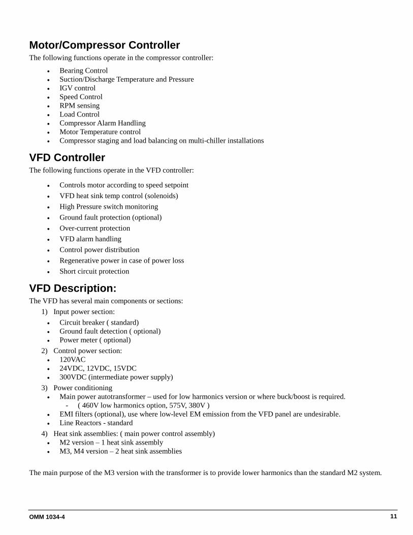
Motor/Compressor Controller The following functions operate in the compressor controller:
• Bearing Control • Suction/Discharge Temperature and Pressure • IGV control • Speed Control • RPM sensing • Load Control • Compressor Alarm Handling • Motor Temperature control • Compressor staging and load balancing on multi-chiller installations
VFD Controller The following functions operate in the VFD controller:
• Controls motor according to speed setpoint • VFD heat sink temp control (solenoids) • High Pressure switch monitoring • Ground fault protection (optional) • Over-current protection • VFD alarm handling • Control power distribution • Regenerative power in case of power loss • Short circuit protection
VFD Description: The VFD has several main components or sections:
1) Input power section: • Circuit breaker ( standard) • Ground fault detection ( optional) • Power meter ( optional)
2) Control power section: • 120VAC • 24VDC, 12VDC, 15VDC • 300VDC (intermediate power supply)
3) Power conditioning • Main power autotransformer – used for low harmonics version or where buck/boost is required.
- ( 460V low harmonics option, 575V, 380V ) • EMI filters (optional), use where low-level EM emission from the VFD panel are undesirable. • Line Reactors - standard
4) Heat sink assemblies: ( main power control assembly) • M2 version – 1 heat sink assembly • M3, M4 version – 2 heat sink assemblies
The main purpose of the M3 version with the transformer is to provide lower harmonics than the standard M2 system.
12 OMM 1034-4
Key VFD Control Signals • VFD enable from Compressor to VFD (relay contact)• Speed reference (command speed) from compressor to VFD (4-20 mA analog)• Compressor RPM sensor output to VFD (digital pulse)• VFD amps to Compressor (Ethernet)
The remaining chiller data, setpoints, and control signals travel between the chiller, compressor, and VFD using an Ethernet network.
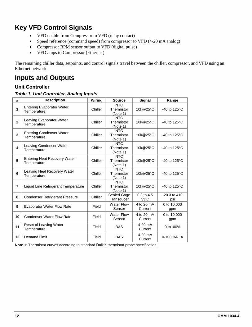
Inputs and Outputs Unit Controller Table 1, Unit Controller, Analog Inputs # Description Wiring Source Signal Range
1 Entering Evaporator Water Temperature Chiller
NTC Thermistor
(Note 1) 10k@25°C -40 to 125°C
2 Leaving Evaporator Water Temperature Chiller
NTC Thermistor
(Note 1) 10k@25°C -40 to 125°C
3 Entering Condenser Water Temperature Chiller
NTC Thermistor
(Note 1) 10k@25°C -40 to 125°C
4 Leaving Condenser Water Temperature Chiller
NTC Thermistor
(Note 1) 10k@25°C -40 to 125°C
5 Entering Heat Recovery Water Temperature Chiller
NTC Thermistor
(Note 1) 10k@25°C -40 to 125°C
6 Leaving Heat Recovery Water Temperature Chiller
NTC Thermistor
(Note 1) 10k@25°C -40 to 125°C
7 Liquid Line Refrigerant Temperature Chiller NTC
Thermistor (Note 1)
10k@25°C -40 to 125°C
8 Condenser Refrigerant Pressure Chiller Sealed Gage Transducer
0.3 to 4.5 VDC
-20.3 to 410 psi
9 Evaporator Water Flow Rate Field Water Flow Sensor
4 to 20 mA Current
0 to 10,000 gpm
10 Condenser Water Flow Rate Field Water Flow Sensor
4 to 20 mA Current
0 to 10,000 gpm
11 Reset of Leaving Water Temperature Field BAS 4-20 mA
Current 0 to100%
12 Demand Limit Field BAS 4-20 mA Current 0-100 %RLA
Note 1: Thermistor curves according to standard Daikin thermistor probe specification.
OMM 1034-4 13
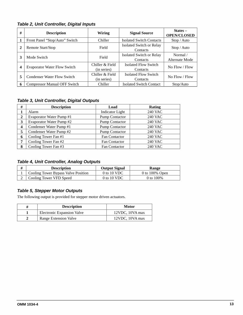
Table 2, Unit Controller, Digital Inputs
# Description Wiring Signal Source States – OPEN/CLOSED
1 Front Panel “Stop/Auto” Switch Chiller Isolated Switch Contacts Stop / Auto
2 Remote Start/Stop Field Isolated Switch or Relay Contacts Stop / Auto
3 Mode Switch Field Isolated Switch or Relay Contacts
Normal / Alternate Mode
4 Evaporator Water Flow Switch Chiller & Field (in series)
Isolated Flow Switch Contacts No Flow / Flow
5 Condenser Water Flow Switch Chiller & Field (in series)
Isolated Flow Switch Contacts No Flow / Flow
6 Compressor Manual OFF Switch Chiller Isolated Switch Contact Stop/Auto
Table 3, Unit Controller, Digital Outputs # Description Load Rating 1 Alarm Indicator Light 240 VAC 2 Evaporator Water Pump #1 Pump Contactor 240 VAC 3 Evaporator Water Pump #2 Pump Contactor 240 VAC 4 Condenser Water Pump #1 Pump Contactor 240 VAC 5 Condenser Water Pump #2 Pump Contactor 240 VAC 6 Cooling Tower Fan #1 Fan Contactor 240 VAC 7 Cooling Tower Fan #2 Fan Contactor 240 VAC 8 Cooling Tower Fan #3 Fan Contactor 240 VAC
Table 4, Unit Controller, Analog Outputs # Description Output Signal Range 1 Cooling Tower Bypass Valve Position 0 to 10 VDC 0 to 100% Open 2 Cooling Tower VFD Speed 0 to 10 VDC 0 to 100%
Table 5, Stepper Motor Outputs The following output is provided for stepper motor driven actuators.
# Description Motor 1 Electronic Expansion Valve 12VDC, 10VA max 2 Range Extension Valve 12VDC, 10VA max

14 OMM 1034-4
Compressor Controller
Table 6, Compressor Controller, Analog Inputs # Description Source Signal Range 1 Compressor Suction Temperature NTC Thermistor 10k@25°C -40 to 125°C 2 Compressor Discharge Temperature NTC Thermistor 10k@25°C -40 to 125°C 3 Suction Refrigerant Pressure Sealed Gage Transducer 0.3 to 4.5 VDC -6.6 to 132 psi 4 Discharge Refrigerant Pressure Sealed Gage Transducer 0.3 to 4.5 VDC -20.3 to 410 psi 5 Rotor Pump Temperature NTC Thermistor 10k@25°C -40 to 125°C 6 Inlet Guide Vane Position Rotary Transducer 0.5 to 4.5 VDC Closed to Open 7 Motor Winding Temperature 1 NTC Thermistor 10k@25°C -40 to 150°C 8 Motor Winding Temperature 2 NTC Thermistor 10k@25°C -40 to 150°C 9 Motor Winding Temperature 3 NTC Thermistor 10k@25°C -40 to 150°C
10 Motor Case Temperature 11 Motor Gap Temperature NTC Thermistor 10k@25°C -40 to 125°C
Table 7, Compressor Controller, Digital Inputs None
Table 8, Compressor Controller, Analog Outputs None
Table 9, Compressor Controller, Digital Outputs # Description Load Output OFF Output ON 1 VFD Enable VFD Compressor OFF Compressor ON 2 Liquid Injection Solenoid (24 VDC, 20 VA max) No Injection Injection 3 Stator Cooling Solenoid (24 VDC, 20 VA max) Cooling OFF Cooling ON
Table 10, Stepper Motor Outputs The following output is provided for stepper motor driven actuators.
# Description Motor 1 Inlet Guide Vane Position 4.2VDC, 30VA max 2 Rotor Cooling 12VDC, 10VA max

OMM 1034-4 15
Optional Harmonic Filters The optional harmonic filter is a device that reduces harmonics. It may be factory-mounted in the chiller power panel or remotely mounted in the field. Operation The harmonic filter is a passive device and there is no operator action required for normal operation. Cleaning Excessive accumulations of dirt on the reactor windings or insulators and capacitor terminals should be removed to permit free circulation of air and to guard against the possibility of insulation breakdown. Particular attention should be given to cleaning the top and bottom ends of the winding assemblies and to cleaning out ventilating ducts. Windings should be lightly cleaned by the use of a vacuum cleaner. If necessary a blower or compressed air may be used but pressure should not exceed 25 psi. Lead supports, tap changers and terminal boards, bushings, and other major insulating surfaces should be brushed or wiped with a dry cloth. The use of liquid cleaners is not recommended due to deteriorating effects on most insulating materials. Periodic Inspection and Maintenance The filter has no moving or active parts and therefore requires only minimal periodic maintenance when installed in a clean and well ventilated environment. Annual maintenance is recommended. This should include: 1. Visual inspection for evidence of loose connections, dirt, moisture, rusting, corrosion, and deterioration of the
insulation, varnish or paint. Observations should be made for signs of overheating and overvoltage creeping. Corrective measures should be taken as necessary.
2. For early detection of any developing hotspots, an infrared scan can be performed while the unit is operating under its heaviest load condition.
3. The unit capacitors are equipped with an internal ‘Tear-Off’ fuse pressure interrupter to prevent explosive failure. At the end of its service life, pressure within a capacitor will build due to the release of gases as its dielectrics breakdown. The covers on the cans are designed to expand or bulge and Tear-Off the internal fuse as this pressure builds. Capacitors should be inspected regularly and replaced when found to have an expanded cover.
CAUTION
Ensure that power to the unit is turned off and safely isolated before replacing failed capacitors or blown fuses. 4. Most units are also equipped with capacitor fuses. Capacitor fuses are intended to provide additional protection
against overloading of the capacitors. A blown fuse can be detected by checking for illumination of the blown fuse indicator when this option has been purchased or by measuring the voltage across the fuse terminals while energized. If voltage is not near zero or the blown fuse indicator is on, the fuse should be replaced.
5. Measuring the current in each of the three phases of the capacitor circuit can be a quick and easy method of determining the condition of the capacitors. The capacitors can be assumed to be in good operating condition when all three phases carry approximately the same amount of load current. Measurements should be taken at the input to the capacitor distribution block and can be done at any loading condition. Phase currents that are imbalanced by more than 10%, indicate a capacitor failure or blown fuse. When the filter capacitor bank has been connected in a wye configuration (ie. Two jumpers create a common point on each set of three capacitors), locating the problem capacitor(s) can be achieved by measuring the voltage between the common neutral point of each set to ground. If the voltage difference is greater than 10 volts, at least one of the capacitors in that set has failed or has a blown fuse. Testing should be conducted annually or whenever the unit seems to be operating in an abnormal manner. The unit is capable of continued operation with some failed capacitors or blown capacitor fuses. Harmonic mitigation performance will be sacrificed however, so it is recommended that all failed capacitors or blown capacitor fuses be replaced as soon as is practically possible after detection.
CAUTION
Service work on this device must be only be performed by technicians trained and experienced on them.

16 OMM 1034-4
Field Wiring Data
Electrical Notes Input power options:
• 3ph 380V 50/60Hz • 3ph 400V 50/60Hz • 3ph 415V 50/60Hz • 3ph 460V 50/60Hz • 3ph 480V 50/60Hz • 3ph 575V 60Hz
Wiring, fuse and wire size must be in accordance with the National Electric Code (NEC).
Important: Voltage unbalance not to exceed 2%.
Power Wiring
Use only copper supply wires with ampacity based on 75°C conductor rating. Connections to terminals must be made with copper lugs and copper wire.
Lug size range is: (3) 3/0 AWG - 500 kc mil.
Short Circuit Current Ratings
WME chillers are available with an optional High Short Circuit Rating HSCCR) or Ultra High Short Circuit
Motor Voltage Standard Panel
Optional High
SCCR
Optional Ultra High
SCCR
3-Ph 380V-480V 35 kA 65 kA 100 kA
575V 25 kA 50 kA N/A
6-Ph 380V-480V 35 kA 65 kA 100 kA
575V N/A N/A N/A
Current Rating (UHSCCR) in lieu of the standard rating (SCCR) as shown in the above table.
3-Phase vs. 6-phase Motors
WME 500 motors are designated as M2 or M3. • "M2 motors are standard 3-phase and the VFD
performs similar to a 6-pulse drive. • "M3 motors are 6-phase (connected to a 3-phase power
supply) and the VFD performs similar to a 12-pulse drive. They provide increased protection against harmonic distortion, but are not required on most applications.
WME 700 motors are 6-phase and designated as M4. The VFD performs similar to a 12-pulse drive.
Notes for field wiring diagram ( page 17) 1 Optional Flow Switches; If field supplied pressure
differential flow switches are used, they must be installed across the vessel and not the pump. They must provide isolated dry contacts at J27. Removing the factory jumpers will correctly put the field switches in series with the factory-mounted switches.
2 CW Reset & Demand Limit; External 4-20mA signals can be wired to J23 for leaving (chilled) water reset and to J26 for demand limit.
3 Tower Bypass Valve & Tower Fan VFD; 0-10VDC analog outputs to these devices.
4 Chiller Remote On/Off Control of unit can be accomplished by connecting a set of isolated dry contacts at J25.
5 Mode Switch; Switch used for ice mode currently not available on WME chillers.
6 Condenser & Evaporator GPM; Connections for 4-20 ma flow signal from field-supplied devices.
7 Alarm Relay; A customer furnished 24 to 240 Vac power for controller alarm relay may be connected at J18. Maximum rating of the alarm relay coil is 25 VA.
8 Evap Water Pump #1 & #2; A digital output for a optional customer supplied 25 VA maximum coil rated, chilled water pump relay. One or two may be wired as shown. This option will cycle the chilled water pump in response to chiller demand.
9 Cond Water Pump #1 & #2; The condenser water pump must cycle with the unit. A customer supplied 25 VA maximum coil rated, condenser water pump relay (one or two) must be wired as shown. Units used in a free-cooling application must have condenser water above 50°F before starting.
10 Tower Fan Staging #1, #2 & #3; Digital outputs for optional customer supplied 25 VA maximum coil rated cooling tower fan relays may be wired as shown. This option will cycle the cooling tower fans as prescribed by the tower control set points.

OMM 1034-4 17
Figure 6, Field Wiring Diagram (see notes on page 16)
NOTE: The “J” terminals blocks are on the top of the back panel under the four knockouts for field wiring.

OM Centrif Micro ΙΙ-2
OMM 1034-4 19
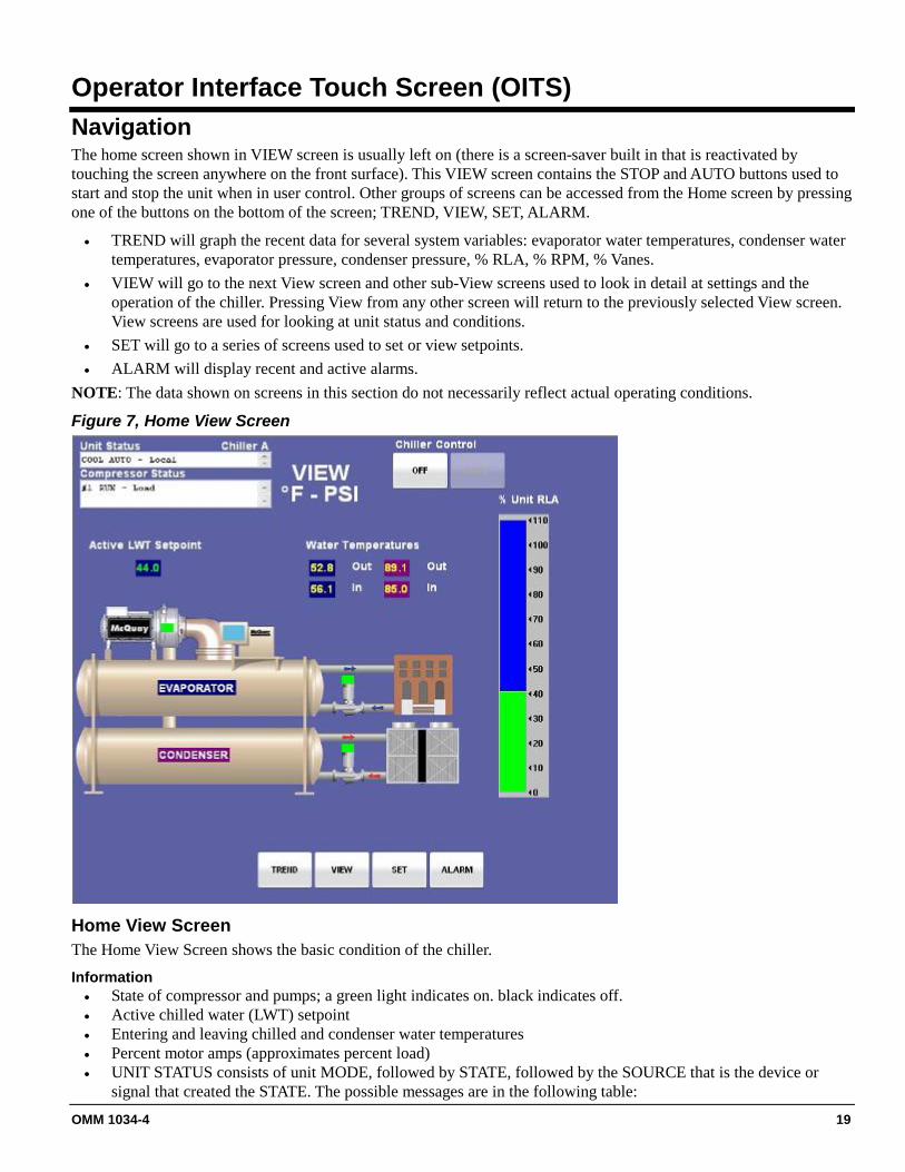
Operator Interface Touch Screen (OITS) Navigation The home screen shown in VIEW screen is usually left on (there is a screen-saver built in that is reactivated by touching the screen anywhere on the front surface). This VIEW screen contains the STOP and AUTO buttons used to start and stop the unit when in user control. Other groups of screens can be accessed from the Home screen by pressing one of the buttons on the bottom of the screen; TREND, VIEW, SET, ALARM.
• TREND will graph the recent data for several system variables: evaporator water temperatures, condenser water temperatures, evaporator pressure, condenser pressure, % RLA, % RPM, % Vanes.
• VIEW will go to the next View screen and other sub-View screens used to look in detail at settings and the operation of the chiller. Pressing View from any other screen will return to the previously selected View screen. View screens are used for looking at unit status and conditions.
• SET will go to a series of screens used to set or view setpoints. • ALARM will display recent and active alarms.
NOTE: The data shown on screens in this section do not necessarily reflect actual operating conditions.
Figure 7, Home View Screen
Home View Screen The Home View Screen shows the basic condition of the chiller.
Information • State of compressor and pumps; a green light indicates on. black indicates off. • Active chilled water (LWT) setpoint • Entering and leaving chilled and condenser water temperatures • Percent motor amps (approximates percent load) • UNIT STATUS consists of unit MODE, followed by STATE, followed by the SOURCE that is the device or
signal that created the STATE. The possible messages are in the following table:

20 OMM 1034-4
Table 11, UNIT STATUS Combinations MODE STATE SOURCE COOL OFF Manual Switch
SHUTDOWN ( See Note) Remote Switch AUTO User BAS Network
Note: Shutdown is the chiller state when in the process of shutting down.
The Home View Screen-Detail gives additional information on the refrigerant pressures and temperatures, compressor speed and other system data. When first booted up, this screen will only show the left side. As soon as one of the details, such as STATE is selected, and from then on, the screen will show information appearing on the right side.
Figure 8, Home View Screen-Detail
Pressing the STATE button will bring up a display of the compressor state superimposed on the View Home Screen-Detail as shown in Figure 8.
Pressing the I/O button will bring up a display of the compressor inputs and output status (I/O) superimposed on the View Home Screen-Detail as shown in Figure 9. These I/Os are to and from the compressor controller.
Range extension position is the percent opening of the range extension valve. The value locks to zero if the feature is not configured.

OMM 1034-4 21
Figure 9, Compressor I/O Screen
Digital Outputs: a green light to the left of a condition indicates it is active. Liquid injection is a user option controlled by a setpoint
Analog Inputs: data from sensors connected to the compressor
Analog Output: compressor speed output
Stepper Outputs: compressor stepper outputs for inlet guide position, rotor cooling, and range extension
Range Extension Position: range extension position is the percent opening of the range extension valve. The value locks to zero if the feature is not configured
22 OMM 1034-4
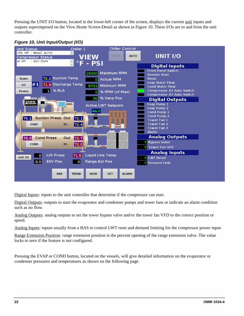
Pressing the UNIT I/O button, located in the lower-left corner of the screen, displays the current unit inputs and outputs superimposed on the View Home Screen-Detail as shown in Figure 10. These I/Os are to and from the unit controller.
Figure 10, Unit Input/Output (I/O)
Digital Inputs: inputs to the unit controller that determine if the compressor can start.
Digital Outputs: outputs to start the evaporator and condenser pumps and tower fans or indicate an alarm condition such as no flow.
Analog Outputs: analog outputs to set the tower bypass valve and/or the tower fan VFD to the correct position or speed.
Analog Inputs: inputs usually from a BAS to control LWT reset and demand limiting for the compressor power input.
Range Extension Position: range extension position is the percent opening of the range extension valve. The value locks to zero if the feature is not configured.
Pressing the EVAP or COND button, located on the vessels, will give detailed information on the evaporator or condenser pressures and temperatures as shown on the following page.

OMM 1034-4 23
Figure 11, Evaporator Screen
Figure 12, Condenser Screen

24 OMM 1034-4
Pressing the Power button, located on the left side of the screen, will access the screen giving power data. Individual line current and voltage values, power factor and kW Hours are only available with the optional Input Power Meter.
Figure 13, Power Screen

OMM 1034-4 25
SET Screens The set screens on the Interface Panel are used to input the many setpoints associated with equipment of this type. MicroTech-E provides an extremely simple method for accomplishing this. Appropriate setpoints are factory set and checked by Daikin Service or a Factory Authorized Service Company during commissioning. However, adjustments and changes are often required to meet job conditions. Certain settings involving pumps and tower operation are always field set.
Pressing the SET button from any other screen accesses the SET screen. Pressing the SET button while on a SET screen will access the SERVICE screen.
The various setpoint groups are in a column on the right side of the screen. Each button contains a number of setpoints grouped together by similar content. For example, The WATER contains various setpoints relating to water temperatures.
NOTE: Some setpoints that do not apply to a particular application may still be listed on the screen. They will be inactive and can be ignored.
The numbered buttons in the second from right column are pressed to select a particular setpoint. The selected setpoint will appear in green on the screen and a description of it (with the range of available settings) will appear in the upper left-hand box.
Figure 14, Typical Setpoint Screen Setpoint Groups
Setpoint Access
Numbers
Current Setpoint Values
Buttons to Access Other Menus Keypad
Current Unit & Compressor Status
Setpoint Description and Range of Values

26 OMM 1034-4
Procedure for Changing a Setpoint A list of setpoints, their default value, their available setting range, and password authority are shown on the page relating to the particular setpoint screen beginning on page 27.
Press the applicable Setpoint Group Button. A complete explanation of setpoint content of each group follows this section.
1) Select the desired setpoint by pressing the numbered button.2) Press the CHANGE button indicating that you wish to change a setpoint value. A keypad dialog box will be
turned on automatically for entering the password.3) O= Operator password : default = 1004) T = Technician level password is reserved for authorized technicians5) Press the appropriate numbers in the keypad box to enter the password. There is a small delay between
pressing the keypad and recording the entry. Be sure that an asterisk appears in the window before pressing thenext number. Press ENTER to return to the SETPOINT screen. The password will remain open for 15 minuteafter initiation and does not need to be re-entered during this period.
6) Press CHANGE again7) The numeric keypad and action buttons in the lower left-hand corner of the screen will be activated. Setpoints
with numeric values can be changed in two ways:• Select the desired value by pressing the numbered buttons. Press ENTER to enter the value or CANCEL to
cancel the transaction.• Press the UP or DOWN button to increase or decrease the value displayed. Press ENTER to enter the value or
CANCEL to cancel the transaction.Some setpoints are text rather than numeric values. For example, LWT Reset Type can be "None" or "4-20 ma". The selection can be made by toggling between choices using the UP or Down button. If dashed lines appear in the setpoint window, it indicates that you have toggled too far and need to reverse direction. Press ENTER to enter the choice or CANCEL to cancel the transaction. Setpoints requiring text entry open an alphanumeric keyboard. Once CHANGE is selected, the CANCEL or ENTER buttons must be pressed before another setpoint can be selected. Additional setpoints can be changed by selecting another setpoint on the screen or by selecting an entirely new group of setpoints.
Range Extension The range extension function is only accessible with the technician password. Consult Daikin Service.
Explanation of Setpoints Each of the setpoint groups of screens are detailed in the following section. The groups are: WATER, UNIT, STAGING, POWER, TOWER, VALVE, ALARMS, BAS In some cases, pressing the button again may display a second page of setpoints in the same group. Pressing SET from any SET screen accesses the SERVICE screen. In other words, it is the second "SET" screen. While containing information and activity buttons for the service technician, it also has valuable information for the operator.
The software version numbers shown in the lower left corner are the controllers' software identification. These numbers may be required by Daikin to answer questions about unit operation or to assist in possible future upgrades of software.

OMM 1034-4 27
Setpoint Screens Figure 15, BAS Setpoint Screen #1
Figure 16, BAS Setpoint Screen #2
Screen details on the following page.

28 OMM 1034-4
Table 12, BAS Screen #1 Setpoints
Description No. Default Range Password Comments
BACnet IP - Foreign Device
Time 15 0 (0) to 65535 Seconds O
The Time-to-Live, in seconds, within which the Chiller (a Foreign Device)
must re-register with the BBMD. BACnet IP -
BBMP IP Address
14 0.0.0.0 = "None
(XXX.XXX.XXX.XXX) where each XXX can be
0 to 255 O
The Internet Protocol (IP) address for the BACnet Broadcast Management Device (BBMD)
to which the chiller is registered.
BACnet IP - Default Gateway 13 None
(XXX.XXX.XXX.XXX) where each XXX can be
0 to 255 O The Internet Protocol (IP) address
of the BACnet IP router.
BACnet IP UDP Port 12
47808 decimal (BAC0
hexadecimal).
0 to 65535 decimal O The User Datagram Protocol (UDP) port number to use on the IP network.
BAC net IP Subnet Mask 11 255.255.2
55.0
(XXX.XXX.XXX.XXX) where each XXX can bo
0 to 255 O Subnet Mask for the
communication module.
BACnet IP - Network Addr 10 172.15.5.8
(XXX.XXX.XXX.XXX) where each XXX can bo
0 to 255 O The four-octet (32-bit) Internet Protocol (IP)
address for the communications module.
BACnet (all) - UTC Offset 9 0 -780 to +780 minutes O
Sets the local time zone by Specifying the zone's offset from Universal Time Coordinated (UTC)
in minutes.Example: US Central Standard Time (CST) is -360.)
BACnet (all) - Daylight Savings
Time 8 None
NO: Do not use Daylight Savings Time.
YES: Use Daylight Savings Time.
O ---
BACnet (all) - APDU Retries 7 3 0 to 10 O
The maximum number of times an Application Protocol Data Unit (APDU) transmission shall be
sent when there is no acknowledgment.
BACnet (all) - APDU Tiimeout 6 3000 milli-
seconds 0 to 60,000 milliseconds O The retry timeout interval (msec) for Application Protocol Data Unit (APDU) transmissions that
require acknowledgment. BACnet (all) - Description 5 None 31characters maximum. O The desired BACnet description
of this particular chiller BACnet (all) - Object Name 4 31 characters maximum. O The unique BACnet Object Name
BACnet (all) - Device Instance 3 3000 0 to 4194302 O The unique BACnet Device
Instance number.
BACnet (all) - English / Metric 2 English
ENGLISH: Use English units. (Deg F, PSI, GPM)
METRIC: Use Metric units. (Deg C, kPa,
liter/sec)
O ---
BAS Network Protocol 1 None
BAS Network Protocol NONE: No BAS network MODBUS: RTU - RS485 LON: LONtalk - FTT-10A BACnet IP: IP - Ethernet
BACnet Ethernet: Ethernet
BACnet MS/TP: RS485
O ---

OMM 1034-4 29
Table 13, BAS Screen #2 Setpoints Description No. Default Range Password Comments
MODBUS - Baud Rate 8 9600 1200, 2400, 4800, 9600,
19200 O Sets the communications baud rate to use on the RS485 network.
MODBUS - Network Address 7 1 1 to 247 O Sets the address to use on the
RS485 network. MODBUS Eng/Metric 6 English English or Metric O ENGLISH: Use English units. (Deg F, PSI, GPM)
METRIC: Use Metric units. (Deg C, kPa, liter/sec) BACnet MS/TP -
Baud Rate 5 38400 9600, 19200, 38400, 76800 O Sets the communications baudrate to use on the
RS485 network.
BACnet MS/TP Max Info Frames 4 5 1 to(5 O
Maximum number of Information Frames that can be sent before the communication module must
pass the token. BACnet MS/TP -
Max Masters 3 127 1 to 127 O Maximum number of master controllers currently on the network.
BACnet MS/TP - MAC Address 2 1 0 to 127 O Unique MAC Address of the communication
module.
BACnet Ethernet - MAC Address 1
XX-XX-XX-XX-XX-XX Each XX can be 00 through
FF hexadecimal O Unique MAC Address of the communication
module.
Figure 17, Alarms Screen

30 OMM 1034-4
Table 14, ALARM Setpoints
Description No. Default Range Pass-word Comments
Condenser Freeze Protect 11 34.0 °F -9.0 to 45.0 °F O
Sets the value of condenser saturated temperature below which the condenser pump is forced ON.
Evaporator Freeze Protect 10 34.0 °F -9.0 to 45.0 °F O
Sets the value of evaporator saturated temperature below which the evaporator pump is forced ON.
Motor Current Threshold 9 5% 3% to 99% T When %RLA is below this SP, motor is considered OFF. When above, motor is considered ON.
Surge Slope Limit 8 20 1 – 99 deg F/min. T
Sets the Surge Temp (ST) slope value above which alarm occurs. Active only if ST > SP7 at start. Deactivated when ST drops below SP7.
Surge Temperature Limit 7 6 2 – 25 deg F T
At start,Surge Temp(ST) is compared to this SP.(ST=Sctn Temp-Evap LWT) if Less:Alarm occurs when ST>2X this SP. if Greater:Slope alarm is active until ST<this SP. Then alarm at 2X this SP.
High Discharge Temp-Stop 6 190 °F 120 to 240 °F T Sets the discharge temperature above which the
compressor is shut down.
High Discharge Temp-Load 5 190 °F 120 to 240 °F T
Sets the discharge temperature above which a forced capacity increase occurs.
High Condenser Pressure 4 140 psi 120 to 240 psi T Sets the condenser pressure above which the compressor is shut down.
Low Evap Pressure, Stop 3 26 psi 10 to 45 psi O Sets the evaporator pressure value below which the compressor is shut down.
Low Evap Pressure-Unload 2 31 psi 20 to 45 psi O Sets the evaporator pressure value below which
a forced capacity decrease occurs.
Low Evap Pressure-Inhibit 1 35 psi 20 to 45 psi O
Sets the evaporator pressure value below which any capacity increase is inhibited.
OMM 1034-4 31
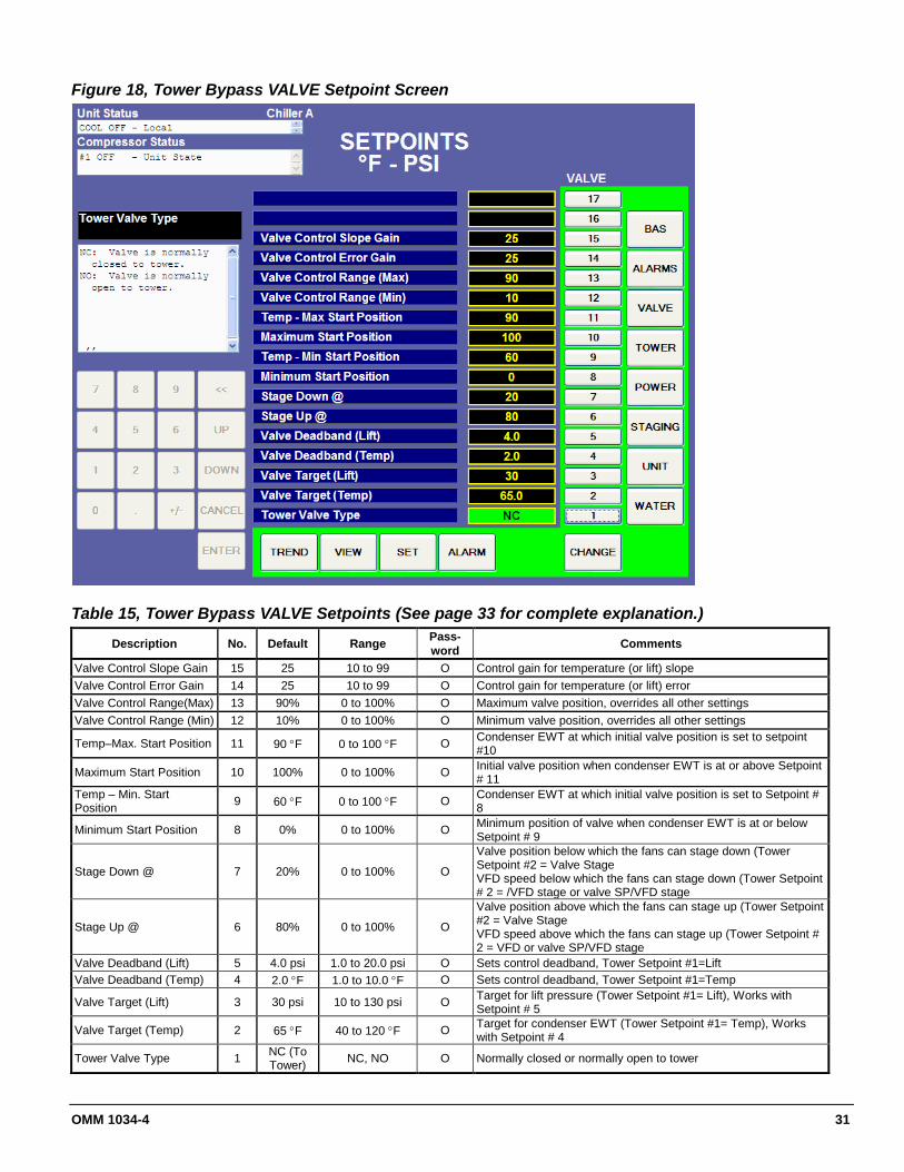
Figure 18, Tower Bypass VALVE Setpoint Screen
Table 15, Tower Bypass VALVE Setpoints (See page 33 for complete explanation.)
Description No. Default Range Pass-word Comments
Valve Control Slope Gain 15 25 10 to 99 O Control gain for temperature (or lift) slope Valve Control Error Gain 14 25 10 to 99 O Control gain for temperature (or lift) error Valve Control Range(Max) 13 90% 0 to 100% O Maximum valve position, overrides all other settings Valve Control Range (Min) 12 10% 0 to 100% O Minimum valve position, overrides all other settings
Temp–Max. Start Position 11 90 °F 0 to 100 °F O Condenser EWT at which initial valve position is set to setpoint #10
Maximum Start Position 10 100% 0 to 100% O Initial valve position when condenser EWT is at or above Setpoint # 11
Temp – Min. Start Position 9 60 °F 0 to 100 °F O Condenser EWT at which initial valve position is set to Setpoint #
8
Minimum Start Position 8 0% 0 to 100% O Minimum position of valve when condenser EWT is at or below Setpoint # 9
Stage Down @ 7 20% 0 to 100% O
Valve position below which the fans can stage down (Tower Setpoint #2 = Valve Stage VFD speed below which the fans can stage down (Tower Setpoint # 2 = /VFD stage or valve SP/VFD stage
Stage Up @ 6 80% 0 to 100% O
Valve position above which the fans can stage up (Tower Setpoint #2 = Valve Stage VFD speed above which the fans can stage up (Tower Setpoint # 2 = VFD or valve SP/VFD stage
Valve Deadband (Lift) 5 4.0 psi 1.0 to 20.0 psi O Sets control deadband, Tower Setpoint #1=Lift Valve Deadband (Temp) 4 2.0 °F 1.0 to 10.0 °F O Sets control deadband, Tower Setpoint #1=Temp
Valve Target (Lift) 3 30 psi 10 to 130 psi O Target for lift pressure (Tower Setpoint #1= Lift), Works with Setpoint # 5
Valve Target (Temp) 2 65 °F 40 to 120 °F O Target for condenser EWT (Tower Setpoint #1= Temp), Works with Setpoint # 4
Tower Valve Type 1 NC (To Tower) NC, NO O Normally closed or normally open to tower

32 OMM 1034-4
Figure 19, Cooling Tower Setpoint Screen (See page 33 for complete explanation.)
Table 16, Tower Fan Settings
Description No. Default Range Pass-word Comments
Stage #3 On (Lift) 13 55 psi 10 to 130 psi O Lift pressure for fan stage #3 on Stage #2 On (Lift) 12 45 psi 10 to 130 psi O Lift pressure for fan stage #2 on Stage #1 On (Lift) 11 35 psi 10 to 130 psi O Lift pressure for fan stage #1 on Stage #3 On (Temp) 10 80 °F 40 to 120 °F O Temperature for fan stage #3 on Stage #2 On (Temp) 9 75 °F 40 to 120 °F O Temperature for fan stage #2 on Stage #1 On (Temp) 8 70 °F 40 to 120 °F O Temperature for fan stage #1 on Stage Differential (Lift) 7 6.0 psi 1.0 to 20.0 psi O Fan staging deadband with Setpoint # 1=Lift Stage Differential (Temp) 6 3.0 °F 1.0 to 10.0 °F O Fan staging deadband with Setpoint #1=Temp
Fan Stage Down Time 5 5 min 1 to 60 min O Time delay between stage up/down event and next stage down
Fan Stage Up Time 4 2 min 1 to 60 min O Time delay between stage up/down event and next stage up
Cooling Tower Stages 3 2 1 to 3 O Number of fan stages used
Twr Valve/Fan VFD Control 2 None
None, Valve Setpoint, Valve Stage, VFD Stage,
Valve SP/VFD Stage
O
None: No tower valve or VFD Valve Setpoint: Valve controls to VALVE SP3(4) & 5(6) Valve Stage: Valve controls between fan stages VFD Stage: 1st fan is VFD controlled, no valve Valve Setpoint/VFD Stage: Both valve and VFD
Tower Control 1 None None,
Temperature, Lift
O None: No tower fan control Temperature: Fan and valve controlled by condenser EWT Lift: Fan and valve controlled by lift pressure
OMM 1034-4 33
Explanation of Tower Control Settings The MicroTech control can control cooling tower fan stages, a tower bypass valve, and/or a tower fan VFD if the chiller has a dedicated cooling tower.
The Tower Bypass Valve position will always control the Tower Fan Staging if Valve Setpoint, Stage Setpoint is selected. Fan staging is determined by Min & Max Tower Valve Position.
There are five possible tower control strategies as noted below and explained in detail later in this section. They are selected from SETPOINT TOWER SP2.
1. NONE, Tower fan staging only. In this mode the tower fan staging (up to 3 stages) is controlled by either the condenser Entering Water Temperature (EWT) or LIFT pressure (difference between the condenser and evaporator pressures). Tower bypass or fan speed are not controlled.
2. VALVE SP, Tower staging with low-limit controlled bypass valve. In this mode the tower fans are controlled as in #1 plus a tower bypass valve is controlled to provide a minimum condenser EWT. There is no interconnection between the fan control and the valve control.
3. VALVE STAGE, Tower staging with stage controlled bypass valve. In this mode the bypass valve controls between fan stages to smooth the control and reduce fan cycling
4. VFD STAGE. In this mode a VFD controls the first fan. Up to 2 more fans are staged on and off and there is no bypass valve.
5. VALVE/VFD, Tower fan control with VFD plus bypass valve control.
Tower Fan Staging Only (NONE) The following settings are used for the Tower Fan Staging Only mode, (SP= setpoint) 1) TOWER SETPOINT Screen
2) See Figure 6, Field Wiring Diagram on page 17 for fan staging field wiring connection points. a) SP1. Select TEMP if control is based on condenser EWT or LIFT if based on compressor lift expressed as a
pressure difference. b) SP2. Select NONE for no bypass valve or fan VFD control. c) SP3. Select one to three fan outputs depending on the number of fan stages to be used. More than one fan can
be used per stage through the use of relays. d) SP4. Select STAGE UP TIME from 1 to 60 minutes. The default value is probably a good starting point. The
value may need to be adjusted later depending on actual system operation. e) SP5. Select STAGE DOWN TIME from 1 to 60 minutes. The default value is probably a good starting point.
The value may need to be adjusted later depending on actual system operation. 3) If TEMP is selected in SP1, use
a) SP6. Select STAGE DIFFERENTIAL in degrees F (degrees C), start with default of 3 degrees F.
b) SP8-11. Set the STAGE ON temperatures consistent with the temperature range over which the condenser EWT is desired to operate. The default values of 70°F, 75°F and 80°F are a good place to start in climates with moderate wet bulb temperatures. The number of STAGE ON setpoints used must be the same as SP3.
4) If LIFT is selected in SP1, use
a) SP7. Select STAGE DIFFERENTIAL in PSI (kPa). Start with default of 6 PSI.
b) SP11-13. Start with default setpoints. The number of STAGE ON setpoints used must be the same as SP3.
34 OMM 1034-4
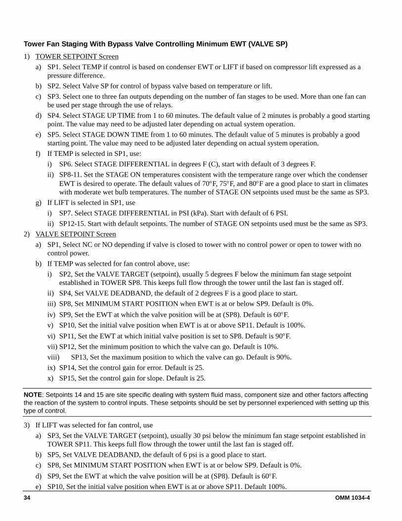
Tower Fan Staging With Bypass Valve Controlling Minimum EWT (VALVE SP) 1) TOWER SETPOINT Screen
a) SP1. Select TEMP if control is based on condenser EWT or LIFT if based on compressor lift expressed as a pressure difference.
b) SP2. Select Valve SP for control of bypass valve based on temperature or lift. c) SP3. Select one to three fan outputs depending on the number of fan stages to be used. More than one fan can
be used per stage through the use of relays. d) SP4. Select STAGE UP TIME from 1 to 60 minutes. The default value of 2 minutes is probably a good starting
point. The value may need to be adjusted later depending on actual system operation. e) SP5. Select STAGE DOWN TIME from 1 to 60 minutes. The default value of 5 minutes is probably a good
starting point. The value may need to be adjusted later depending on actual system operation. f) If TEMP is selected in SP1, use:
i) SP6. Select STAGE DIFFERENTIAL in degrees F (C), start with default of 3 degrees F. ii) SP8-11. Set the STAGE ON temperatures consistent with the temperature range over which the condenser
EWT is desired to operate. The default values of 70°F, 75°F, and 80°F are a good place to start in climates with moderate wet bulb temperatures. The number of STAGE ON setpoints used must be the same as SP3.
g) If LIFT is selected in SP1, use i) SP7. Select STAGE DIFFERENTIAL in PSI (kPa). Start with default of 6 PSI. ii) SP12-15. Start with default setpoints. The number of STAGE ON setpoints used must be the same as SP3.
2) VALVE SETPOINT Screen a) SP1, Select NC or NO depending if valve is closed to tower with no control power or open to tower with no
control power. b) If TEMP was selected for fan control above, use:
i) SP2, Set the VALVE TARGET (setpoint), usually 5 degrees F below the minimum fan stage setpoint established in TOWER SP8. This keeps full flow through the tower until the last fan is staged off.
ii) SP4, Set VALVE DEADBAND, the default of 2 degrees F is a good place to start. iii) SP8, Set MINIMUM START POSITION when EWT is at or below SP9. Default is 0%. iv) SP9, Set the EWT at which the valve position will be at (SP8). Default is 60°F. v) SP10, Set the initial valve position when EWT is at or above SP11. Default is 100%. vi) SP11, Set the EWT at which initial valve position is set to SP8. Default is 90°F. vii) SP12, Set the minimum position to which the valve can go. Default is 10%. viii) SP13, Set the maximum position to which the valve can go. Default is 90%. ix) SP14, Set the control gain for error. Default is 25. x) SP15, Set the control gain for slope. Default is 25.
NOTE: Setpoints 14 and 15 are site specific dealing with system fluid mass, component size and other factors affecting the reaction of the system to control inputs. These setpoints should be set by personnel experienced with setting up this type of control.
3) If LIFT was selected for fan control, use a) SP3, Set the VALVE TARGET (setpoint), usually 30 psi below the minimum fan stage setpoint established in
TOWER SP11. This keeps full flow through the tower until the last fan is staged off. b) SP5, Set VALVE DEADBAND, the default of 6 psi is a good place to start. c) SP8, Set MINIMUM START POSITION when EWT is at or below SP9. Default is 0%. d) SP9, Set the EWT at which the valve position will be at (SP8). Default is 60°F. e) SP10, Set the initial valve position when EWT is at or above SP11. Default 100%.

OMM 1034-4 35
f) SP11, Set the EWT at which initial valve position is set to SP8. Default is 90°F. g) SP12, Set the minimum position to which the valve can go. Default is 10%. h) SP13, Set the maximum position to which the valve can go. Default is 100%. i) SP14, Set the control gain for error. Default is 25. j) SP15, Set the control gain for slope. Default is 25.
NOTE: Setpoints 14 and 15 are site-specific dealing with system fluid mass, component size and other factors affecting the reaction of the system to control inputs. These setpoints should be set by personnel experienced with setting up this type of control.
See Figure 6 on page 17 for fan staging and bypass valve field wiring connection points.
Tower Staging with Bypass Valve Controlled by Fan Stage (VALVE STAGE) This mode is similar to #2 above except that the bypass valve setpoint changes to be set at the same point of whatever fan stage is active rather than just maintaining a single minimum condenser EWT. In this mode the valve controls between fan stages and tries to maintain the fan stage setting in effect. When it is max open or max closed (staging up or down) and the temperature (or lift) moves to the next fan stage, the valve will go the opposite extreme setting. This mode reduces fan cycling. This mode is programmed the same as Mode #2 above except that in SETPOINT, TOWER, SP2, VALVE STAGE is selected instead of VALVE SP.
Fan VFD, No Bypass Valve (VFD STAGE) The fan VFD mode assumes the tower is driven by one large fan. Set-up is as above except in SETPOINT, TOWER, SP2, VALVE/VFD is selected.
Initial Valve Position
Max Start Position Set Point (90%)
Min Start Position Set Point (10%)
Temp-Max Start Position
@ Setpoint (90°F)
Temp-Min Start Position @ Setpoint
(60°F)

36 OMM 1034-4
Figure 20, Power Setpoint Screen
Table 17, Power Setpoints
Description No. Default Range Pass-word Comments
Over Voltage Limit 11 550 342 to 633 Volts Sets the over voltage limit
Nameplate RLA 10 280 Amps 100 to 600 Amps T
Sets the Rated Load Amps (RLA) per compressor phase as given on the Daikin nameplate - Load Side Phase Data.
Overload Factor 9 1.1 1.001 to 1.249 T VFD over-current trip occurs at Nameplate RLA times Overload Factor.
VFD Min Speed offset % 8 0 -5 to +5 Correction to minimum speed calculation
VFD Minimum Speed 7 70% 70 to 100 % T Sets the minimum speed at which the VFD can operate. Has priority over SPs 8 & 9.
Soft Load Ramp Time 6 5 1 to 60 Minutes O Sets the time period over which the %RLA limit is increased from the SP 5 value to 100%. Used with SPs 5 & 6.
Initial Soft Load Limit 5 40% 10 to 100 % O Sets the initial %RLA limit for the soft load ramp. Used with SPs 5 & 7.
Soft Load Enable 4 OFF ON, OFF O ON: Soft loading is ON using SPs 5 & 6. OFF: Soft Loading is disabled.
Maximum Amps 3 100% 10 to 100 % T Inhibits capacity increase above the %RLA Unloading is forced at 5% above this value.
Minimum Amps 2 5% 5 to 80 % T Sets the %RLA below which unloading is inhibited.
Demand Limit Enable 1 Off ON, OFF O
ON: Limits %RLA to a value set by the Demand Limit analog input, where:
4mA = 0 %RLA 20mA = 100 %RLA OFF: The Demand Limit input is ignored.
OMM 1034-4 37
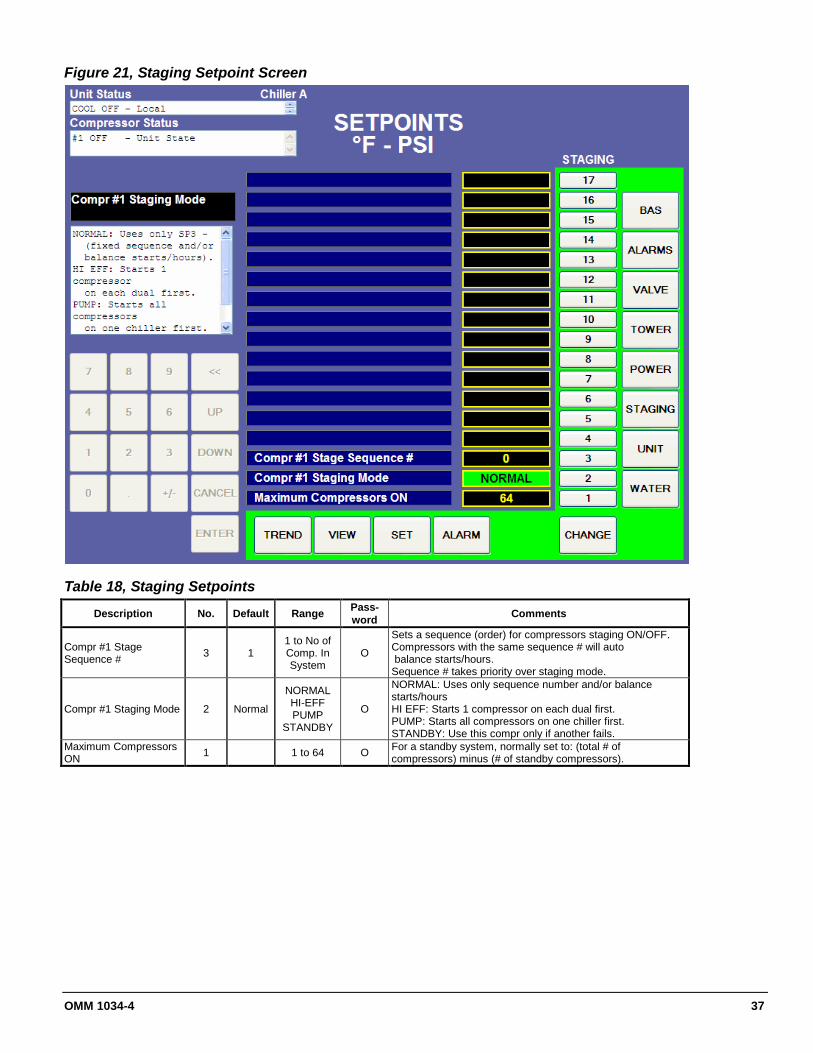
Figure 21, Staging Setpoint Screen
Table 18, Staging Setpoints
Description No. Default Range Pass-word Comments
Compr #1 Stage Sequence # 3 1
1 to No of Comp. In System
O
Sets a sequence (order) for compressors staging ON/OFF. Compressors with the same sequence # will auto balance starts/hours. Sequence # takes priority over staging mode.
Compr #1 Staging Mode 2 Normal
NORMAL HI-EFF PUMP
STANDBY
O
NORMAL: Uses only sequence number and/or balance starts/hours HI EFF: Starts 1 compressor on each dual first. PUMP: Starts all compressors on one chiller first. STANDBY: Use this compr only if another fails.
Maximum Compressors ON 1 1 to 64 O For a standby system, normally set to: (total # of
compressors) minus (# of standby compressors).

38 OMM 1034-4
Figure 22, Unit Setpoint Screen
Table 19, Unit Setpoints
Description No. Default Range Pass-word Comments
Liquid Injection 14 Off Off, Auto T
EXV Total Offset 13 0 0 to 100% O The EXV position is offset by this constant amount.
EXV Balance Offset 12 0 -10 to 10 Deg F O
Adds to difference between Condenser Approach and Suction Superheat. A more positive value raises the evaporator liquid level.
EXV Balance Gain 11 2 0 to 5 O
Gain factor applied to: (Condenser Approach - Suction Superheat + EXV Balance Offset).
An increase makes the balance function more sensitive
Unload Timer 10 30 sec 10 to 240 Seconds O Sets the maximum amount of time a compressor will unload before it turns OFF (goes to postlube).
Stop To Start Timer 9 1 Min 0 to 20 Minutes O Sets the amount of time that must occur after a compressor stops
until it can restart. Start To Start Timer 8 1 Min 0 to 60 Minutes O Sets the amount of time that must occur after a compressor starts
until it can start again. Evap Recirculate Timer
7 0.5 min 0.2 to 5.0 Minutes O Sets the amount of time the evaporator pump must run before a compressor can start.
Nominal Capacity 6 500/700 0-9999 O Sets the nominal capacity of an individual compressor. Used to
decide when to turn OFF a compressor (stage down) Continued next page.

OMM 1034-4 39
Description No. Default Range Pass-word Comments
Condenser Pump
5 #1 Only
#1 ONLY, #2 ONLY AUTO
#1 PRiMARY, #2 PRIMARY
O
#1 ONLY: Use only pump #1 #2 ONLY: Use only pump #2 AUTO: Balance hours between #1 and #2. #1 PRIMARY: Use #1. If it fails, then use #2. #2 PRIMARY: Use #2. If it fails, then use #1
Evaporator Pump 4 #1 Only
#1 ONLY, #2 ONLY AUTO
#1 PRiMARY, #2 PRIMARY
O
#1 ONLY: Use only pump #1 #2 ONLY: Use only pump #2 AUTO: Balance hours between #1 and #2. #1 PRIMARY: Use #1. If it fails, then use #2. #2 PRIMARY: Use #2. If it fails, then use #1.
Control Source 3 USER USER, SWITCH, BAS O
Sets control source for Unit Enable, Mode, & LWT SPs. USER: Control is from touchscreen or remote user
SWITCH: As USER except Mode is controlled by the Mode digital input. BAS: Control is from the BAS network.
Unit Mode 2 COOL Cool, ICE, HEAT O COOL: Maintains evaporator LWT at WATER-SP1.
Unit Enable 1 OFF OFF AUTO O
OFF: Compressors, pumps, & fans are OFF. AUTO: Evap pump is ON, Compressors, condenser pump, & fans will operate as needed to maintain water temperature.
Figure 23, Water Setpoint Screen
Detail table on following page.

40 OMM 1034-4
Table 20, Water Setpoints Description No. Default Range Password Comments
Condenser Flow Full Scale 11 3000 200 to 10,000 GPM O Sets the full scale (20mA) value for the condenser flow rate analog input
Evaporator Flow Full Scale 10 3000 200 to 10,000 GPM O Sets the full scale (20mA) value for the evaporator flow rate analog input
Maximum Reset Delta-T 9 0.0 0.0 to 20.0 Deg F O Reset Type (SP9) = Return: Sets the maximum LWT reset that can occur.
Reset Type (SP9) = 4-20mA: Sets amoumt of reset at 20mA input. Start Reset Delta-T 8 10 0.0 to 20.0 Deg F O Sets evaporator delta-T above which Return reset begins.
LWT Reset Type 7 None Return 4-20mA O
Reset raises LWT setpoint Return (uses SPs 10 & 11) 4-20mA (4mA=None,20mA=Max asset by SP 11)
Maximum LWT Rate 6 5.0 0.1 to 5.0
Deg F/min O If the LWT rate is above this value, capacity increase is inhibited. Minimum LWT Rate 5 0.1 0.1 to 5.0
Deg F/min O Sets the value below which an additional compressor can stage on.
Stage Delta-T 4 1.0 0.5 to 5.0 Deg F O Sets amount leaving water must go above set point for next compressor to start.
Startup Delta-T 3 3 Deg F 0.0 to 10.0 Deg F O Sets amount leaving water must go above for first compressor to start.
Shutdown Delta-T 2 3 Deg F 0.0 to 3.0 Deg F O Sets amount leaving water must drop below setpoint for last compressor to stop.
Leaving Water Temp - COOL 1 44 °F 35 to 80 Deg F O Sets control target for evaporator leaving water temperature
in COOL mode.
Service Screens Figure 24, Service Screen
Screen explanation on following page.

OMM 1034-4 41
A matrix in the middle of the screen shows the chillers and compressors attached to the network. A green box indicates that a given controller is present and communicating. This is an effective means for verifying communication between units and compressors on the same network. SELECT LANGUAGE allows toggling between the available languages. The language can be set separately for display or history, which is used for alarm and trend files. Currently only English is available. The UNAUTHORIZE/AUTHORIZE button is used to access a keypad dialog box to enter a password.
• O= Operator password : default = 100• T = Technician level password is reserved for authorized technicians
Date/Time in the upper-right corner is pressed to set the correct date and time.
Downloading Data Trend data can be downloaded for review and storage as a personal computer file or printed as a hard copy for future reference. This is valuable for troubleshooting potential problems or reviewing the chiller’s general performance.
The last 30 days of history data can be downloaded from the controller, one day at a time.
To download history data from the chiller: 1) Install a USB memory stick into an open USB slot on the chiller controller. These slots are located on the top
and bottom of the metal bracket holding the main chiller controller (see page 10 for panel layout). (NOTE: one of these slots will have a USB cable going to J13. DO NOT UNPLUG THIS CABLE). Do not remove the main memory stick located behind the metal bracket. Thirty MB per day should be available on the USB memory stick for data accumulation. There is no warning of insufficient space.
2) Navigate to the OITS ALARM screen.3) Highlight a day on the calendar.4) Press download button. The controller will display a notification of "download complete" at the end.
To analyze downloaded data: 1. The chiller data is in binary format and must be compiled into spreadsheet format with a separate program.
Download trend"WME Trend Tool" from www.DaikinApplied.com/Magnitude on the Download tab, under Application Software.
Troubleshooting: 1) "Error mounting the USB drive". Action: Remove and reinstall USB memory stick and repeat. If problem
persists, try a different USB memory stick. Name brand memory sticks are recommended. 2) No data appears on the disk after download. Cause: no data available for that day.

42 OMM 1034-4
Chiller Alarms Figure 25: Active Alarm Screen
The Active Alarm screen is accessible when an active alarm exists on the unit by pressing the red alarm signal on any screen. Pressing any ALARM on the screen will open another screen that will show the condition of the chiller at the time of alarm. The last eight alarms are arranged in order of occurrence, with the most recent on top. Once the abnormal condition is corrected, pressing the "CLEAR" key will clear the alarm. Both current active alarms and cleared alarms (there may be more than one of each) are displayed. Alarms with a red bar to the left are current, uncleared alarms. Cleared alarms have a black bar.
• Alarms shown in red are for equipment protection control and cause a compressor shutdown,
• Alarms shown in yellow or blue will inhibit loading, or load or unload the compressor to correct a potential problem or indicate a condition requiring attention but not serious enough to cause a shutdown.
The date/time and cause of the alarm are displayed. Pressing any alarm will open a snapshot screen showing the unit operating parameters at the time of failure. Touching the gray area of this screen will close it. After eliminating the cause of the alarm, clear the alarm by pressing the CLEAR button. This will clear the alarm from the register and allow the unit to restart after going through the start sequence. The alarm button will return to its normal color. However, if the cause of the alarm is not remedied, the alarm is still active and the alarm message will remain active. The unit will not begin its starting sequence. Always remedy the cause of an alarm before attempting to clear it.
See Table 21 for alarm details.

OMM 1034-4 43
Table 21, Alarm Details and Troubleshooting Guide Severity Clear Screen Text Occurs When Troubleshooting
Shutdown Manual Discharge Temperature High Temp > High Discharge Temperature SP Causes: Low or No Condenser Water
Flow
Shutdown Manual Mechanical High Pressure Digital Input on VFD= High Pressure Causes: Loss of condenser water flow (this switch connects directly to the VFD) HPS failure (from MBR 201/15) Condenser water flow low.
Shutdown Manual Motor Stator Temperature High
Analog Motor Temp (any sensor) > Motor Temp SP
Rotor and/or stator cooling circuit fault
Causes: Motor stator cooling solenoid not open, rotor cooling stepper motor not functioning correctly, Motor rotor superheat or gain setpoints incorrect ( contact factory)
Shutdown Manual Motor Gap Temperature High Motor Gap Temperature > 130°F
Rotor and/or stator cooling circuit fault. Causes: Motor stator cooling solenoid not open
Motor rotor cooling stepper motor not opening, Motor rotor superheat or gain setpoints incorrect ( contact factory)
Shutdown Manual Rotor Pump Superheat Low
Rotor Pump Superheat (Rotor Pump Temp – Saturated Suction Temp) < 5°F for 5 minutes with compressor running
Rotor cooling circuit fault. Causes: rotor cooling valve stuck open,
Motor rotor superheat or gain setpoints incorrect ( contact factory)
Shutdown Manual Surge Temperature
FOR Surge Temp (ST) = Sctn Temp – Evap LWT: Compressor Surge detected.
IF (ST < Surge Temp Limit SP at compressor start)
Causes: Compressor Surge/Stall line not set properly. See setpoint section.
THEN (alarm if ST > 2 X Surge Temp Limit SP) Loss of condenser or evaporator GPM ELSE (alarm if ST slope > Surge Slope Limit SP Low Evaporator or condenser GPM
until ST < Surge Temp Limit SP , then Condenser fouling alarm if ST > 2 X Surge Temp Limit SP).
Shutdown Manual Motor Start Failure (Motor speed not = speed command Motor did not start. Causes: VFD control
failure, Check VFD enable signal wiring, Check VFD breaker AND Compressor ON) for > 15 seconds
Shutdown Manual No Compressor Stop %RLA > Motor Current Threshold SP with Compressor OFF for 30 sec
Motor running while it should be off. Causes: VFD enable relay failure
VFD CTs failure VFD loss of communications.
Shutdown Manual VFD Fault VFD Fault AND Compressor State = FLOAT, START, RUN, or UNLOAD
General VFD fault. Normally accompanied by another fault.
Shutdown Manual VFD Reference Fault Failure to calculate speed pulse reference position at 900 rpm
Speed pulse feedback not present:
Causes: Speed sensor fault, Speed sensor wiring fault, VFD controller fault
Shutdown Manual VFD Loss of Motor Sync Loss of VFD phase lock loop synchronization Speed pulse loss while running
Causes: Speed sensor fault, Speed sensor wiring fault, VFD controller fault
Shutdown Manual VFD Motor Stall No speed pulse detected when motor should be running
Speed pulse feedback not present: Causes: Speed sensor fault Speed sensor wiring fault
VFD controller fault
Shutdown Manual VFD Speed Command Fault Commanded speed fault
Motor speed outside of expected range. Causes: Speed sensor fault, Speed sensor wiring fault,
VFD controller fault
Continued next page.

44 OMM 1034-4
Severity Clear Screen Text Occurs When Troubleshooting
Shutdown Manual VFD Cooling Fan Fault Failure of fan monitor circuit Fan is stopped. Causes: Check fan CT wiring, check CT for open circuit, fan
failure
Shutdown Manual VFD Processor Fault VFD processor hardware or software trap fault Causes: Processor fault or overheating. Check fan operation for proper airflow. If
persistent, replace controller.
Shutdown Manual VFD Maintenance Mode Maintenance mode switch activated (B17 – MBR 201/14)
Jumper missing. See VFD schematic. Jumper required for normal chiller
operation
Shutdown Manual Suction Pressure Sensor Fault
Sensor shorted or open Causes: Sensor wiring fault, sensor fault
(Input voltage < 0.2 OR > 4.6 volts)
Shutdown Manual Discharge Pressure Sensor Fault
Sensor shorted or open Causes: Sensor wiring fault, sensor fault
(Input voltage < 0.2 OR > 4.6 volts)
Shutdown Manual Condenser Rfr Ckt #1 Pressure Sensor Fault
Sensor shorted or open Causes: Sensor wiring fault, sensor fault
(Input voltage < 0.2 OR > 4.6 volts)
Shutdown Manual Condenser Rfr Ckt #2 Pressure Sensor Fault
Sensor shorted or open Causes: Sensor wiring fault, sensor fault
(Input voltage < 0.2 OR > 4.6 volts)
Shutdown Manual Suction Temperature Sensor Fault
Sensor shorted or open Causes: Sensor wiring fault, sensor fault
(Input voltage < 0.2 OR > 4.6 volts)
Shutdown Manual Discharge Temperature Sensor Fault
Sensor shorted or open Causes: Sensor wiring fault, sensor fault
(Input voltage < 0.2 OR > 4.6 volts)
Shutdown Manual Motor Gap Temperature Sensor Fault
Sensor shorted or open Causes: Sensor wiring fault, sensor fault
(Input voltage < 0.2 OR > 4.6 volts)
Shutdown Manual Rotor Pump Temperature Sensor Fault
Sensor shorted or open Causes: Sensor wiring fault, sensor fault
(Input voltage < 0.2 OR > 4.6 volts)
Shutdown Manual Compressor Surge/ Bearing Orbit
Mag bearings exceed allowable orbit or sensor fault
Causes: Compressor dynamic load change. Compressor surge. Improperly
set stall/surge line setpoints Bearing controller fault or bearing amplifier fault. Contact factory if
persistent.
Shutdown Manual Communications Fault Loss of communications between compressor and chiller controller
Check wiring and verify correct software versions
Shutdown Manual Evaporator Leaving Water Temperature Sensor Fault
Sensor shorted or open (Input voltage < 0.2 OR > 4.6 volts) AND Unit Mode = COOL or ICE Causes: Sensor wiring fault, sensor fault
Shutdown Manual Condenser Leaving Water Temperature Sensor Fault
Sensor shorted or open (Input voltage < 0.2 OR > 4.6 volts) AND Unit Mode = Heat Causes: Sensor wiring fault, sensor fault
Shutdown Manual Software Fault Controller internal check failure Causes: Compressor controller fault. If persistent, contact factory.
Shutdown Manual Evaporator Water Flow Loss
Evaporator Flow DI = No Flow for > 12 sec with compressor running
Causes: Loss of evaporator flow, evaporator pump off, evap head gasket leaking or missing, sensor wiring fault,
evaporator flow sensor failure
Shutdown Manual Condenser Water Flow Loss
Condenser Flow DI = No Flow for > 20 sec with compressor running OR no flow in START state
at a point (Pre-Start Timer SP + 30 sec) after Pressure Ratio is OK
Causes: Loss of condenser flow, condenser pump off, condenser head
gasket leaking or missing, sensor wiring fault, condenser flow sensor failure
Limit Auto Low Evaporator Pressure – Inhibit Loading Suction Pressure < (Low Evap Press SP)+3psi
Causes: Low evaporator water flow rate, low refrigerant in chiller, setpoints incorrect for operating conditions
Continued next page.

OMM 1034-4 45
Severity Clear Screen Text Occurs When Troubleshooting
Limit Auto Evaporator Pressure Low (Freeze)
Saturated Suction Temp < Evaporator Freeze SP
Causes: Low evaporator water flow rate, low refrigerant in chiller, setpoints incorrect for operating conditions
Limit Auto Condenser pressure Low (Freeze) Saturated Cond Temp < Condenser Freeze SP
Causes: Low evaporator water flow rate, low refrigerant in chiller, setpoints incorrect for operating conditions
Limit Auto Discharge Temperature High
Temperature > High Discharge Temperature-Load SP AND Causes: Low or No Condenser Water
Flow Suction superheat < 15°F
Notice None Software Problem (Compressor) Controller internal check failure Causes: Compressor control fault.
Contact factory if persistent.
Limit Manual Evaporator Pump #1 Fault No flow indicated for (5 sec) with Evaporator
Pump #1 ON AND [the other pump is available (per the Evap Pump SP) AND has not faulted]
Evaporator flow not detected.
Causes: improper pump wiring
Limit Manual Evaporator Pump #2 Fault No flow indicated for (5 sec) with Evaporator
Pump #2 ON AND [the other pump is available (per the Evap Pump SP) AND has not faulted]
Evaporator flow not detected.
Causes: improper pump wiring
Limit Manual Condenser Pump #1 Fault No flow indicated for (5 sec) with Condenser
Pump #1 ON AND [the other pump is available (per the Evap Pump SP) AND has not faulted]
Condenser flow not detected.
Causes: improper pump wiring
Limit Manual Condenser Pump #2 Fault No flow indicated for (5 sec) with Condenser
Pump #2 ON AND [the other pump is available (per the Evap Pump SP) AND has not faulted]
Condenser flow not detected.
Causes: improper pump wiring
Limit Manual Evaporator Entering Water Temperature
Sensor Fault
Sensor fault (Input voltage < 0.2 OR > 4.6 volts) AND the LWT Reset Type SP is set to RETURN Causes: Sensor wiring fault, sensor fault
Notice Auto Evaporator Entering Temperature Sensor Fault
Sensor is open or shorted Causes: Sensor wiring fault, sensor fault
(Input voltage < 0.2 OR > 4.6 volts)
Notice Auto Condenser Entering Temperature Sensor Fault
Sensor is open or shorted Causes: Sensor wiring fault, sensor fault
(Input voltage < 0.2 OR > 4.6 volts)
Notice Auto Condenser Leaving Temperature Sensor Fault
Sensor is open or shorted Causes: Sensor wiring fault, sensor fault
(Input voltage < 0.2 OR > 4.6 volts)
Notice Auto Liquid Line #1 Refrigerant Temperature Sensor Fault
Sensor is open or shorted Causes: Sensor wiring fault, sensor fault
(Input voltage < 0.2 OR > 4.6 volts)
Notice None System Fault Controller internal fault Causes: controller fault. If persistent contact factory.

46 OMM 1034-4
Trend Screens Figure 26, Trend History Screen
This screen plots the parameters shown over various time frames; 8 = eight hours, 2 = two hours, 1/3 = 20 min., < and > move the screen to the right or left. NOW displays current status.
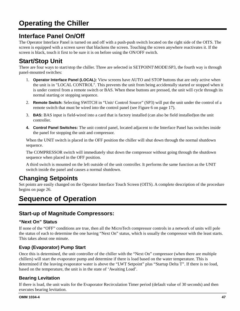
OMM 1034-4 47
Operating the Chiller
Interface Panel On/Off The Operator Interface Panel is turned on and off with a push-push switch located on the right side of the OITS. The screen is equipped with a screen saver that blackens the screen. Touching the screen anywhere reactivates it. If the screen is black, touch it first to be sure it is on before using the ON/OFF switch.
Start/Stop Unit There are four ways to start/stop the chiller. Three are selected in SETPOINT\MODE\SP3, the fourth way is through panel-mounted switches:
1. Operator Interface Panel (LOCAL): View screens have AUTO and STOP buttons that are only active when the unit is in "LOCAL CONTROL". This prevents the unit from being accidentally started or stopped when it is under control from a remote switch or BAS. When these buttons are pressed, the unit will cycle through its normal starting or stopping sequence.
2. Remote Switch: Selecting SWITCH in “Unit/ Control Source” (SP3) will put the unit under the control of a remote switch that must be wired into the control panel (see Figure 6 on page 17).
3. BAS: BAS input is field-wired into a card that is factory installed (can also be field installed)on the unit controller.
4. Control Panel Switches: The unit control panel, located adjacent to the Interface Panel has switches inside the panel for stopping the unit and compressor.
When the UNIT switch is placed in the OFF position the chiller will shut down through the normal shutdown sequence. The COMPRESSOR switch will immediately shut down the compressor without going through the shutdown sequence when placed in the OFF position. A third switch is mounted on the left outside of the unit controller. It performs the same function as the UNIT switch inside the panel and causes a normal shutdown.
Changing Setpoints Set points are easily changed on the Operator Interface Touch Screen (OITS). A complete description of the procedure begins on page 26.
Sequence of Operation
Start-up of Magnitude Compressors: “Next On” Status If none of the “OFF” conditions are true, then all the MicroTech compressor controls in a network of units will pole the status of each to determine the one having “Next On” status, which is usually the compressor with the least starts. This takes about one minute.
Evap (Evaporator) Pump Start Once this is determined, the unit controller of the chiller with the “Next On” compressor (when there are multiple chillers) will start the evaporator pump and determine if there is load based on the water temperature. This is determined if the leaving evaporator water is above the “LWT Setpoint” plus “Startup Delta T”. If there is no load, based on the temperature, the unit is in the state of ‘Awaiting Load’.
Bearing Levitation If there is load, the unit waits for the Evaporator Recirculation Timer period (default value of 30 seconds) and then executes bearing levitation.

48 OMM 1034-4
Cond (Condenser) Pump Start After levitation is confirmed, the controller starts the Condenser Pump and checks for condenser flow before starting the first compressor.
Compressor Start The compressor starts when the following conditions are met:
1) Condenser flow present for 5-seconds (condenser state is RUN) 2) Vanes are at the start position 3) Pre-start timer expired
Starting the compressor is accomplished by closing the VFD enable relay in the compressor controller. The VFD ramps to 900 rpm for WME 500 and 700 rpm for WME 700, waits at this speed until motor synchronization occurs, then ramps up to the VFD minimum speed value.
Compressor Run The compressor that is running will signal all other compressors (including compressor on other chillers when multiple chillers are networked together) when it reaches full load. 1) Percent RLA exceeds the “Maximum Amps” setpoint (typically 100%) or the Active-Amp-Limit from an external-limiting source.
2) Evaporator (suction) Saturation pressure drops below the “Low Evap Pressure Inhibit” setpoint.
3) Actual compressor RPM is at its maximum speed capability and the vanes are within 5% of the “Maximum Vane Position” setpoint. The maximum speed capability is when it exceeds 99% of Max RPM limit for the compressor or the VFD has reached an internal limit preventing further increase in speed.
Capacity Control: During the compressor run state, the chiller will modulate to maintain the evaporator leaving water temperature at the set point. The status window will indicate the operating mode: Speed control, Inlet Guide Vane (IGV) control, or Range Extension System control. The chiller will pick the optimum capacity control mode for best efficiency.
• Speed Control: IGV is 100%, Range Extension is 0% and capacity is adjusted using compressor speed.
• IGV Control: Speed has been reduced to the minimum speed for the operating conditions and capacity is adjusted using inlet guide vanes. Range Extension Valve is set for 0%.
• Range Extension Control: Speed and IGV at their minimum for the operating conditions and the capacity is adjusted using the range extension valve. This mode provides greater unloading capability at high lift conditions.
Note: the options for capacity control mode are in High Lift Mode setpoint in the SERVICE group on the setpoint screen (technician password required). As lift and load conditions vary, the minimum speed and minimum IGV position will vary. In general, the higher the lift, the higher the minimum speed and minimum IGV position.
Staging Compressors Off: The setpoint of ‘Nominal Capacity’ is used for defining the point to stage off a compressor on a multi-chiller system. With each compressor having its ‘Nominal Capacity’ defined, then the network, which is load balanced, continues to unload when below setpoint. Each compressor keeps computing the spare capacity of the network. When the designated ‘Next Off’ sees enough spare capacity, it will turn off. Then similarly, in about 40 seconds, a new compressor will be designated as the ‘Next Off’ and the spare capacity will continue to be calculated between the remaining compressors. Compressors continue to unload and stage off until there is only one compressor running. It will shut off when the water temperature reaches the LWT Setpoint minus the Shutdown Delta T.
Staging Compressors On The Stage Delta-T setpoint is used to define when another compressor must stage on. The compressor with Next On will start when the leaving water temperature exceeds the value of the active LWT plus the Stage Delta-T.

OMM 1034-4 49
Troubleshooting
The primary troubleshooting method is to use the interface panel (OITS) to determine the alarm status, I/O status, unit state, and trend data. If this method is not successful, the next step is to determine if all controllers are present, powered up, fully booted up, and are communicating normally. All controllers have tell-tale LEDs that should be lit to determine powered-up state. Control power starts from the Intermediate Power Supply (IPS) in the VFD panel with a few exceptions. The IPS powers a variety of smaller power supplies for control power, the bearings, and most auxiliary systems. The control power for the cabinet fans, ground fault and VFD cooling solenoids comes from a control power transformer.
Troubleshooting Chart PROBLEM POSSIBLE
CAUSES/CONDITION POSSIBLE CORRECTIVE STEPS
Controls won't boot up Check state of LEDs on chiller controller, compressor controller, and VFD
controller. LEDs should be lit.
If no power Check DC voltage distribution board LEDs.
LEDs are not lit
Check IPS. Check fuses into IPS. Check small fuse on IPS PCB ( 110V). Check control power transformer.
One LED is not lit Check fuses/breakers into power supplies. If persistent, identify corresponding power supply and repair/replace.
VFD will not start
Check OITS alarms. Check control harness to VFD, enable signal, 24VDC power, rpm signal. Check VFD communication cable, Ethernet. Check VFD voltage breakout board that all LED's are lit. Check that all VFD control cables are plugged in and fully seated.
Chiller will not start Check sequence of operation. Check chiller OITS State screen to determine what state the unit is in. Check alarms.
VFD starts but shuts off on alarm Check Alarm codes.
Follow VFD troubleshooting chart. Inlet Guide Vane (IGV) alarm IGV feedback doesn't match setpoint on I/O OITS screen.
Bearing alarm During operation, Out of orbit alarm due to surge/ stall.
OITS data missing
If data is from compressor data
Verify Compressor communication present. Look for lit up green boxes in chiller controller on "SET" screen #2. If not, check Ethernet cable and that compressor controller board LEDs are lit. If yes, reboot chiller.
If data is from VFD Check communication cable. Cycle power to reset VFD controller. Verify LEDs lit on VFD controller. Check power supply.
If data from power meter Verify power meter communication cable wiring. Verify power meter configuration.
OITS data missing If data is from chiller controller Check that sensors are wired properly. Check that LEDs are lit on chiller controller. Check power supply.
Controller unhealthy alarm Verify communications cable is properly connected. Reboot chiller

50 OMM 1034-4
Operation with Failed OITS The touchscreen does not have any control function; it is only a window into the unit’s controller and operation. Chiller operation is not affected by a failed touchscreen. The touchscreen (OITS) is the primary user interface to the chiller. If this screen is not operating as expected, use the following troubleshooting procedure:
Indication; Screen is blank, power indicator is green.
Procedure: Screen is in screen saver mode. Touch screen and image will appear. Indication; Screen is blank, power indicator is unlit.
Problem: Screen has been powered off. Procedure: Press power button on lower outside edge of screen.
Indication; Screen is blank, power indicator is unlit.
Problem: Screen is not receiving power, Procedure: Ensure power cable is plugged into screen and controller.
Indication; Screen is blank, power indicator is unlit.
Problem: Unit controller is not powered. Procedure: Check to see if LEDs are lit/blinking within chiller controller box. If not, contact chiller service.
Indication; Screen is blank, power indicator is unlit
Problem: Touchscreen failure Procedure: Replace touchscreen.
Indication; Screen is working but touch function isn't working.
Problem: Disconnected serial cable. Procedure: Ensure cable is connected, reboot chiller.
Indication; Screen is working but touch function isn't working.
Problem: Touchscreen failure Procedure: Replace touchscreen. As temporary measure, install USB mouse on chiller controller to replace the touch function. Plug USB mouse into spare USB port on chiller controller.
As a temporary replacement for a completely failed touchscreen,
1) Install a VGA monitor using cable from chiller controller box. (Blue plug) 2) Plug USB mouse into spare USB port on chiller controller.

OMM 1034-4 51
Maintenance
External Sensors and Valve Locations
Suction Pressure
Suction Temperature
IGV Stepper Mtr Control & IGV Position Sensor
VFD Control Cable
Compressor Sensor Harness
Ethernet Connection
300VDC Power
High Pressure Switch
Discharge Pressure Sensor
Discharge Temp Sensor

52 OMM 1034-4
Flow Switch
Water Temperature Sensor
Liquid Line Temperature Sensor
Electronic Expansion Valve
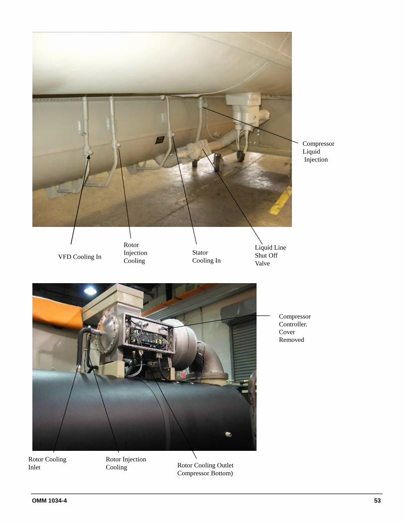
OMM 1034-4 53
VFD Cooling In
Rotor Injection Cooling
Stator Cooling In
Liquid Line Shut Off Valve
Compressor Liquid Injection
Rotor Cooling Inlet
Rotor Injection Cooling Rotor Cooling Outlet
Compressor Bottom)
Compressor Controller. Cover Removed

54 OMM 1034-4
Table 22, HFC-134a Pressure/Temperature Chart HFC-134a Temperature Pressure Chart
°F PSIG °F PSIG °F PSIG °F PSIG
6 9.7 46 41.1 86 97.0 126 187.3
8 10.8 48 43.2 88 100.6 128 192.9
10 12.0 50 45.4 90 104.3 130 198.7
12 13.2 52 47.7 92 108.1 132 204.5
14 14.4 54 50.0 94 112.0 134 210.5
16 15.7 56 52.4 96 115.9 136 216.6
18 17.1 58 54.9 98 120.0 138 222.8
20 18.4 60 57.4 100 124.1 140 229.2
22 19.9 62 60.0 102 128.4 142 235.6
24 21.3 64 62.7 104 132.7 144 242.2
26 22.9 66 65.4 106 137.2 146 249.0
28 24.5 68 68.2 108 141.7 148 255.8
30 26.1 70 71.1 110 146.3 150 262.8
32 27.8 72 74.0 112 151.1 152 270.0
34 29.5 74 77.1 114 155.9 154 277.3
36 31.3 76 80.2 116 160.9 156 284.7
38 33.1 78 83.4 118 166.0 158 292.2
40 35.0 80 86.7 120 171.1 160 299.9
42 37.0 82 90.0 122 176.4 162 307.8
44 39.0 84 93.5 124 181.8 164 315.8
Routine Maintenance Due to the magnetic bearing design, no yearly oil sampling or oil system maintenance is required. See maintenance Schedule on page 60.
Refrigerant Cycle Maintenance of the refrigerant cycle includes maintaining a log of the operating conditions, and checking that the unit has the proper refrigerant charge. At every inspection suction, and discharge pressures should be noted and recorded, as well as condenser and chiller water temperatures. The suction line temperature at the compressor should be taken at least once a month. Subtracting the saturated temperature equivalent of the suction pressure from this will give the suction superheat. Extreme changes in sub-cooling and/or superheat over a period of time indicates a losse of refrigerant or possible deterioration or malfunction of the expansion valves. Proper superheat setting is 1- 3 degrees F at full load. Such a small temperature difference can be difficult to measure accurately. Another method is to measure the compressor discharge superheat, the difference between the actual discharge temperature and the saturated discharge temperature. The discharge superheat should be between 10 and 14 degrees F at full load. The liquid injection must be deactivated (by closing the valve in the feed line) when taking the discharge temperature. The superheat will increase linearly to 55 degrees F (30 degrees C) at 10% load. The MicroTech E interface panel can display all superheat and sub-cooling temperatures.

OMM 1034-4 55
Figure 8, Chiller P & I Diagram
NOTE: All valves indicated with reference numbers should be open for chiller operation.

56 OMM 1034-4
Electrical System 1. Maintenance of the electrical system involves the general requirement of keeping contacts clean and
connections tight and checking on specific items as follows:
2. The compressor current draw should be checked and compared to nameplate RLA value. Normally, the actualcurrent will be lower, since the nameplate rating represents full load operation. Also check all pump and fanmotor amperages, and compare with nameplate ratings.
3. At least once a quarter, all equipment protection controls except compressor overloads should be made tooperate and their operating points checked. A control can shift its operating point as it ages, and this must bedetected so the controls can be adjusted or replaced. Pump interlocks and flow switches should be checked tobe sure they interrupt the control circuit when tripped.
4. Tighten all power terminal connections in the VFD quarterly.5. The compressor motor resistance to ground should be checked and logged semi-annually. This log will track
insulation deterioration. A reading of 50 megohms or less indicates a possible insulation defect or moistureand must be further checked.
! CAUTIONNever Megger a motor while in a vacuum. Severe motor damage can result.
6. The centrifugal compressor must rotate clockwise, as view from the suction side of the compressor. This can be determined by looking in the sight glass mounted on the side of the compressor. In this sight glass, the rotation will result in a downward movement.If the operator has any reason to suspect the very unlikely occurrence of the power system connections between the VFD and motor been altered (phases reversed), the compressor must be jogged to check rotation. For assistance, call your local Daikin Service location.
Cleaning and Preserving A common cause of service calls and equipment malfunction is dirt. This can be prevented with normal maintenance. The system components most subject to dirt are:
1) Remove and clean strainers in chilled water system and condenser water system at every inspection.
2) Inspect the condenser tubes annually for fouling and clean if required. The dished water heads (aka end-bells, water boxes) should be removed with care due to their weight. One method follows:
• After draining water, remove all but four head bolts at roughly 10 and 2 o’clock and 4 and 8 o’clock.• Loosen these remaining four bolts to enable the head to be separated from the tube sheet sufficiently for
a clevis pin or hook to be inserted into an open bolt hole at the top of the head.• Attach a hoist to the pin or hook, lift the head to remove weight from the remaining bolts, remove the
bolts and carefully remove the head.• Do not try to install an eyebolt with machine threads into the head vent fitting, which has pipe threads.• Reverse this procedure to mount the head, using a new gasket.

OMM 1034-4 57
Seasonal Servicing Prior to shutdown periods and before starting up again, the following service procedures must be completed.
Annual Shutdown Where the chiller can be subject to freezing temperatures, the condenser and chiller must be drained of all water. Dry air blown through the condenser will aid in forcing all water out. Removal of condenser heads is also recommended. The condenser and evaporator are not self-draining and tubes must be blown out. Water permitted to remain in the piping and vessels can rupture these parts if subjected to freezing temperature.
Forced circulation of antifreeze through the water circuits is one method of avoiding freeze up.
1) Take measures to prevent the shutoff valve in the water supply line from being accidentally turned on.
2) If a cooling tower is used, and if the water pump will be exposed to freezing temperatures, be sure to removethe pump drain plug and leave it out so any water that can accumulate will drain away.
3) Electrically disconnect the compressor. Set the manual UNIT ON/OFF switch in the Unit Control Panel to theOFF position.
4) Check for corrosion and clean and paint rusted surfaces.
5) Clean and flush water tower for all units operating on a water tower. Make sure tower blowdown or bleed-off is operating. Set up and use a good maintenance program to prevent “liming up” of both tower and condenser. It should be recognized that atmospheric air contains many contaminants that increase the need for proper water treatment. The use of untreated water can result in corrosion, erosion, sliming, scaling or algae formation. It is recommended that the service of a reliable water treatment company be used. Daikin assumes no responsibility for the results of untreated or improperly treated water.
6) Remove condenser heads at least once a year to inspect the condenser tubes and clean if required.
Annual Startup This is a good time to check all the motor winding resistance to ground. Semi-annual checking and recording of this resistance will provide a record of any deterioration (this would be unusual) of the winding insulation. All new units have well over 100 megohms resistance between any motor terminal and ground.
Whenever great discrepancies in readings occur, or uniform readings of less than 50 megohms are obtained, the motor cover must be removed for inspection of the winding prior to starting the unit. Uniform readings of less than 5 megohms indicate motor failure is imminent and the motor should be replaced or repaired. Repair before failure occurs can save a great deal of time and labor spent in the cleanup of a system after a motor burnout.
1) Check and tighten all electrical connections.2) Replace the drain plug in the cooling tower pump if it was removed at shutdown time the previous season.3) Reconnect water lines and turn on supply water. Flush condenser and check for leaks.
Repair of System Pressure Relief Valve Replacement Current condenser designs use two relief valves separated by a three-way shutoff valve (one set). This three-way valve allows either relief valve to be shut off, but at no time can both be shut off. In the event one of the relief valves is leaking in the two valve set, these procedures must be followed: • If the valve closest to the valve stem is leaking, back seat the three-way valve all the way, closing the port to the
leaking pressure relief valve. Remove and replace the faulty relief valve. The three-way shutoff valve must remain either fully back seated or fully forward to normal operation. If the relief valve farthest from the valve stem is leaking, front seat the three-way valve and replace the relief valve as stated above.
• The refrigerant must be pumped down into the condenser before the evaporator relief valve can be removed.
58 OMM 1034-4
Pumping Down If it becomes necessary to pump the system down, extreme care must be used to avoid damage to the evaporator from freezing. Always make sure that full water flow is maintained through the chiller and condenser while pumping down. To pump the system down, close all liquid line valves. With all liquid line valves closed and water flowing, start the compressor. Pump the unit down until the MicroTech E controller cuts out at approximately 20 psig. It is possible that the unit might experience a mild surge condition prior to cutout. If this should occur, immediately shut off the compressor. Use a portable condensing unit to complete the pump down, condense the refrigerant, and pump it into the condenser or pumpout vessel using approved procedures. A pressure regulating valve must always be used on the drum being used to build the system pressure. Also, do not exceed the test pressure given above. When the test pressure is reached disconnect the gas cylinder. Pressure Testing No pressure testing is necessary unless some damage was incurred during shipment. Damage can be determined upon a visual inspection of the exterior piping, checking that no breakage occurred or fittings loosened. Service gauges should show a positive pressure. If no pressure is evident on the gauges, a leak may have occurred, discharging the entire refrigerant charge. In this case, the unit must be leak tested to determine the location of the leak. Leak Testing In the extremely rare case of a loss of the entire refrigerant charge, the unit must be checked for leaks prior to charging the complete system. This can be done by charging enough refrigerant into the system to build the pressure up to approximately 10 psig (69 kPa) and adding sufficient dry nitrogen to bring the pressure up to a maximum of 125 psig (860 kPa). Leak test with an electronic leak detector. Halide leak detectors do not function with HFC-134a. Water flow through the vessels must be maintained anytime refrigerant is added or removed from the system.
! DANGERDo not use oxygen or a mixture of R-22 and air to build up pressure, as an explosion can occur which will cause serious
personal injury or death.
If any leaks are found in welded or brazed joints, or it is necessary to replace a gasket, relieve the test pressure in the system before proceeding. Brazing is required for copper joints. After making any necessary repair, the system must be evacuated as described in the following section.
Evacuation After it has been determined that there are no refrigerant leaks, the system must be evacuated using a vacuum pump with a capacity that will reduce the vacuum to at least 1000 microns of mercury. A mercury manometer, or an electronic or other type of micron gauge, must be connected at the farthest point from the vacuum pump. For readings below 1000 microns, an electronic or other micron gauge must be used. The triple evacuation method is recommended and is particularly helpful if the vacuum pump is unable to obtain the desired 1 millimeter of vacuum. The system is first evacuated to approximately 29 inches of mercury. Dry nitrogen is then added to the system to bring the pressure up to zero pounds. Then the system is once again evacuated to approximately 29 inches of mercury. This is repeated three times. The first pull-down will remove about 90% of the non-condensables, the second about 90% of that remaining from the first pull-down and, after the third only 1/10-1% non-condensables will remain.
Charging the System Model WME water chillers are leak tested at the factory and shipped with the correct charge of refrigerant as indicated on the unit nameplate. In the unusual event that the refrigerant charge is lost for any reason, the system should be charged as follows after first repairing any leaks that are found and evacuating the system.
1) Connect the refrigerant drum to the gauge port on the liquid line shutoff valve and purge the charging linebetween the refrigerant cylinder and the valve. Then open the valve to the mid-position.
2) Turn on the cooling tower water pump and chilled water pump and allow water to circulate through thecondenser and the chiller. (It will be necessary to manually close the condenser pump starter.)

OMM 1034-4 59
3) If the system is under a vacuum, stand the refrigerant drum with the connection up, and open the drum andbreak the vacuum with refrigerant gas to a saturated pressure above freezing.
4) With a system gas pressure higher than the equivalent of a freezing temperature, invert the charging cylinderand elevate the drum above the condenser. With the drum in this position, valves open, water pumps operating,liquid refrigerant will flow into the condenser. Approximately 75% of the total requirement estimated for theunit can be charged in this manner.
5) After 75% of the required charge has entered the condenser, reconnect the refrigerant drum and charging lineto the service valve on the bottom of the evaporator. Again purge the connecting line, stand the drum with theconnection up, and place the service valve in the open position.
IMPORTANT: At this point, the charging procedure should be interrupted and prestart checks made before attempting to complete refrigerant charge. The compressor must not be started at this time. (Preliminary check must first be completed.)
IMPORTANT: It is of utmost importance that all local, national, and international regulations concerning the handling and emission of refrigerants are observed.
Notes on Heat Exchangers: 1) Approach temperature (the difference between the leaving water temperature and the saturated refrigerant
temperature) of either the condenser or evaporator is a good indication of tube fouling, particularly in the condenser, where constant flow usually prevails. Daikin's high efficiency heat exchangers have very low design approach temperatures, in the order of one to one and one-half degrees F.
2) The chiller interface touch screen can display the water and the saturated refrigerant temperatures. Simplesubtraction will give the approach temperature, which is a vital indicator of the evaporator and condenser heattransfer efficiency. It is recommended that benchmark readings (including condenser pressure drop to confirmfuture flow rates) be taken during startup and then periodically afterward. An approach increase of two-degrees ormore would indicate that excessive tube fouling could be present. Higher than normal discharge pressure and motorcurrent are also good indicators
3) Evaporators in closed fluid circuits with treated water or anti-freeze are not normally subject to fouling, however itis prudent to check the approach temperature periodically.
4) Performed when contracted for, not part of standard initial warranty service.

60 OMM 1034-4
Maintenance Schedule
Maintenance Check List Item
Dai
ly
Wee
kly
Mon
thly
Qua
rter
ly
Ann
ually
5-Yr
As
Req
’d
I. Unit· Operational Log O · Analyze Operational Log O · Refrigerant Leak Test Chiller O · Test Relief Valves or Replace X
II. Compressor· Vibration Test Compressor X
A. Motor · Meg. Windings X · Ampere Balance (within 10% at RLA) O · Terminal Check (Infrared temperature measurement) X · Motor Cooling Filter Drier Pressure Drop X
- Motor Winding resistance ( milli-ohm) X - Bearing Coil Winding resistance ( milli-ohm) X
III. Controls A. Operating Controls
· Calibrate Temperature Sensors/Transducers X · Calibrate Pressure Transducers X · Check Vane Control Setting and Operation X · Verify Motor Load Limit Control X · Verify Load Balance Operation (interconnected chillers) X
B. Protective Controls · Test Operation of:
Alarm Relay X Pump Interlocks X High and Low Pressure Cutouts X
IV. Condenser A. Evaluation of Temp Approach (NOTE 1) O B. Test Water Quality V C. Clean Condenser Tubes (NOTE 3) X X D. Eddy current Test - Tube Wall Thickness V E. Seasonal Protection X
V. Evaporator A. Evaluation of Temp Approach (NOTE 1) O B. Test Water Quality V C. Clean Evaporator Tubes (NOTE 3) X D. Eddy current Test - Tube Wall thickness V X E. Seasonal Protection X
VI. Expansion Valves A.Operational Evaluation (Superheat Control) X
VII. Starter(s) A. Examine Contactors (hardware and operation) X B. Verify Overload Setting and Trip X C. Test Electrical Connections (Infrared temp measurement) X
KEY:O = Performed by in-house personnel. X = Performed by Daikin authorized service personnel V = Normally performed by third parties.

OMM 1034-4 61
Service Programs
It is important that any air conditioning system receive adequate maintenance if the full equipment life and full system benefits are to be realized.
Maintenance should be an ongoing program from the time the system is initially started. A full inspection should be made after 3 to 4 weeks of normal operation on a new installation, and on a regular basis thereafter.
Daikin offers a variety of maintenance services through the local Daikin Service office, its worldwide service organization, and can tailor these services to suit the needs of the building owner. Most popular among these services is the Daikin Comprehensive Maintenance Contract.
For further information concerning the many services available, contact your local Daikin Service office.
Operator Training
Training courses for Centrifugal Maintenance and Operation are held through the year at the Daikin Training Center in Staunton, Virginia. The school duration is three and one-half days and includes instruction on basic refrigeration, MicroTech controllers, enhancing chiller efficiency and reliability, MicroTech troubleshooting, system components, and other related subjects. Further information can be found on www.DaikinApplied.com or call Daikin at 540-248-0711 to speak to the Training Department.
Warranty Statement
Limited Warranty All Daikin equipment is sold pursuant to Daikin's Standard Terms and Conditions of Sale and Limited Product Warranty. Consult your local Daikin Representative for warranty details. Refer to form 933-430285Y. To find your local representative, go to www.DaikinApplied.com.


© 2013 Daikin Applied • (800) 432-1342 • www.DaikinApplied.com OMM 1034-4 (11/12)
Daikin Training and Development Now that you have made an investment in modern, efficient Daikin equipment, its care should be a high priority. For training information on all Daikin HVAC products, please visit us at www.DaikinApplied.com and click on training, or call 540-248-9646 to speak to the Training Department.
Warranty All Daikin equipment is sold pursuant to Daikin's Standard Terms and Conditions of Sale and Limited Product Warranty. Consult your local Daikin Representative for warranty details. Refer to form 933-430285Y. To find your local representative, go to www.DaikinApplied.com
This document contains the most current product information as of this printing. For the most up-to-date product information, please go to www.DaikinApplied.com.