MCGM Road Spec Volume -II
176
MUNICIPAL CORPORATION OF GREATER MUMBAI ROAD DEPARTMENT VOLUME-II TECHNICAL SPECIFICATIONS FOR ROAD WORKS 2013
-
Upload
kishan-gohil -
Category
Documents
-
view
231 -
download
0
Transcript of MCGM Road Spec Volume -II

8/19/2019 MCGM Road Spec Volume -II
http://slidepdf.com/reader/full/mcgm-road-spec-volume-ii 1/176
MUNICIPAL CORPORATION OFGREATER MUMBAI
ROAD DEPARTMENT
VOLUME-II
TECHNICAL SPECIFICATIONS FOR
ROAD WORKS
2013
8/19/2019 MCGM Road Spec Volume -II
http://slidepdf.com/reader/full/mcgm-road-spec-volume-ii 2/176
ROADS SCHEDULE 2013
Municipal Corporation of Greater Mumbai
Foreword
Ever since establishment of Bombay Municipal Corporation (now Municipal Corporation of Greater
Mumbai) in 1888 by the erstwhile British rulers in India, in the last 125 years of the history of its
existence MCGM has catered to every aspect of the citizen of Mumbai that can be conceived of.
Look to heritage buildings like Victoria Terminus (Chhatrapati Shivaji Terminus), Office of Municipal
Corporation, Dadabai Naoroji Road, Dr. Babasaheb Ambedkar Road, Marine Drive (Netaji Subhash
Road), Prince of Wales Museum, Gateway of India, Malabar Hill Reservoir, Nair Hospital, Lokmanya
Tilak Hospital, KEM Hospital etc which are the service centers for the citizens. Municipal Services
have also been provided in the suburban and extended suburban areas merged in 1950 & 1957
respectively. The obligatory duties are performed well but still there is need to improve in quantity
and quality of services to be provided to the citizens.
Ethical governance and righteous work culture will certainly bring positive changes in design and
implementation of projects. One may take an example of the first Municipal Head Quarter Building,
that was completed in year 1893, in four years, designed by F W Stevens and the execution part
was dealt by Project Engineer Shri Rao Saheb Sitaram Khanderrao Vaidya, who executed the
project of 77.70m high structure and saved Rs.68,000/- as against estimated cost of Rs. 11.80
Lakhs.
The need is to work with precision and accuracy. There shall be harmony between planning and
execution so as to evolve best economics with focused goals.
MCGM is one of the largest local self governments in the Asian Continent. In observance of historic
traditions of strong civic activism, with the change in time and living conditions to match with the
urbanization, MCGM has focused in providing variety of engineering services viz, storm water drain,
sewerage, water supply, roads, bridges, solid waste management, environmental services. Beside
this, the Corporation is also providing dedicated services in the Health sector by establishing Major
and Peripheral hospitals.
To update and modernize the mechanism being used for working on related projects from the stage
of conceptualization to execution, the need was realized to revise prevailing “Schedule Of Rates”
along with specifications which were in operation with various departments and being prepared
individually as per their need and revised at different span of time, resulting into various anomalies.
To overcome all these, it was essential to revise the schedule of rates, not only with simple
mechanized revision but incorporating major changes to keep up with the pace of urbanization,
civilization, construction techniques / mechanization and voluminous developments by restructuring

8/19/2019 MCGM Road Spec Volume -II
http://slidepdf.com/reader/full/mcgm-road-spec-volume-ii 3/176
ROADS SCHEDULE 2013
Municipal Corporation of Greater Mumbai
items in the schedule to cover all requirements. This exercise would provide comfort with designs
and field necessities and will assist in effective checks on creation of extra items during execution.
A conscious decision has been taken to prepare Unified Schedule of Rates to keep pace with the
changing time; a first step forward in this direction. Since long time, there have been demands made
by the stake holders like Municipal Engineers and Contractors to remove non-uniformity, anomaliesand discrepancies in various schedules of rates for work contracts of various departments of MCGM.
Every department had its own expertise and way of functioning which got reflected in its independent
schedule of rates, which however, had no linkage with the fair market rates and schedules of other
departments, resulting into extra items and fair rates. In place of earlier 9 Schedule Of Rates, the
Unified Schedule of Rates is an effort and seeks to rectify the defects, discrepancies and non
uniformities which will provide ease and accuracy of estimation to the Engineers.
In view of the enormous and voluminous nature of work, keeping time frame in perspective and
above all, to ensure professionalism, the work of preparation of Unified Schedule of Rates (USR)
was awarded to the eminent consultants M/s. TATA Consulting Engineers Ltd. M/s. TATA Consulting
Engineers Ltd were directed to conduct a integrated factual market research for major materials from
stockists/manufacturers/dealers and to study schedules of rates of Govt. bodies like C.P.W.D.,
P.W.D. etc The new Rate Analysis are based on Factual Market research done by M/s.TATA
Consulting Engineers Ltd.
The anomalies in rate are minimized after extensive market research and collection of quotations
from reputed large scale stockists/dealers, and also after comparison with rates of CPWD, PWD etc.
The Unified Scheduled of Rates is linked with its comprehensive specifications of basic importantactivities so as to have clarity in execution. These specifications follow a chronology of general
scope of the item, material required, processing of material, construction operation, finishing and
mode of measurement. Rigid Standard Operating Procedures (SOPs) and complete control on
processes will certainly satisfy quality parameter. The need for checking the quality of construction is
quite apparent and shall be ensured throughout the construction process. To achieve this, the
Unified Scheduled of Rates incorporates quality assurance procedures.
All the rates are also linked to their detailed specifications and wherever required, with drawings.
Though there are about 12500 items, every item is now given a Unique Code No. which will
eliminate the repetition.
It has been our endeavor to include all the necessary modern materials and technologies in Unified
Schedule of Rates, for example, the concept of green building, which will go a long way to have
control on creation of extra items and fair rates. A salient feature of this Unified Schedule of Rates is
’Starring of items’ specified categorically which can be used only at certain works or locations.

8/19/2019 MCGM Road Spec Volume -II
http://slidepdf.com/reader/full/mcgm-road-spec-volume-ii 4/176
ROADS SCHEDULE 2013
Municipal Corporation of Greater Mumbai
Another salient feature is ’Dynamic Rate System’ which will be based on study of data base of
quantities and bidding prices of awarded contracts on the basis of which necessary corrections can
be applied to the Unified Schedule of Rates at specified intervals. The MCGM will be now be in a
position to revise the Unified Scheduled of Rates every year, after incumbency period of M/s.TATA
Consulting Engineers Ltd of one year, to work with and correct the system as and when necessary.
I am sure that this ’Unified Scheduled of Rates’ will be a milestone in civic governance by MCGM.
This publication shall be of great help and guidance to the officers engaged in the project work of
MCGM.
A.M.C. (Project) Municipal Commissioner
8/19/2019 MCGM Road Spec Volume -II
http://slidepdf.com/reader/full/mcgm-road-spec-volume-ii 5/176
STANDARD SPECIFICATIONS FOR ROAD WORKS SP-RW
MUNICIPAL CORPORATION OF GREATER MUMBAI Page 1
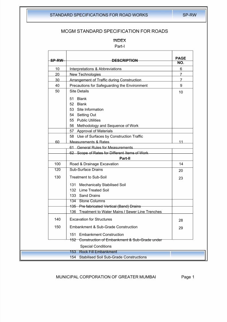
MCGM STANDARD SPECIFICATION FOR ROADS
INDEX
Part-I
SP-RW- DESCRIPTIONPAGENO.
10 Interpretations & Abbreviations 6
20 New Technologies 7
30 Arrangement of Traffic during Construction 7
40 Precautions for Safeguarding the Environment 9
50 Site Details 10
51 Blank
52 Blank
53 Site Information
54 Setting Out
55 Public Utilities
56 Methodology and Sequence of Work
57 Approval of Materials
58 Use of Surfaces by Construction Traffic
60 Measurements & Rates 11
61 General Rules for Measurements
62 Scope of Rates for Different Items of WorkPart-II
100 Road & Drainage Excavation 14
120 Sub-Surface Drains 20
130 Treatment to Sub-Soil 23
131 Mechanically Stabilised Soil
132 Lime Treated Soil
133 Sand Drains
134 Stone Columns
135 Pre fabricated Vertical (Band) Drains
136 Treatment to Water Mains I Sewer Line Trenches
140 Excavation for Structures 28
150 Embankment & Sub-Grade Construction 29
151 Embankment Construction
152 Construction of Embankment & Sub-Grade under
Special Conditions
153 Rock Fill Embankment
154 Stabilised Soil Sub-Grade Constructions
8/19/2019 MCGM Road Spec Volume -II
http://slidepdf.com/reader/full/mcgm-road-spec-volume-ii 6/176
STANDARD SPECIFICATIONS FOR ROAD WORKS SP-RW
MUNICIPAL CORPORATION OF GREATER MUMBAI Page 2
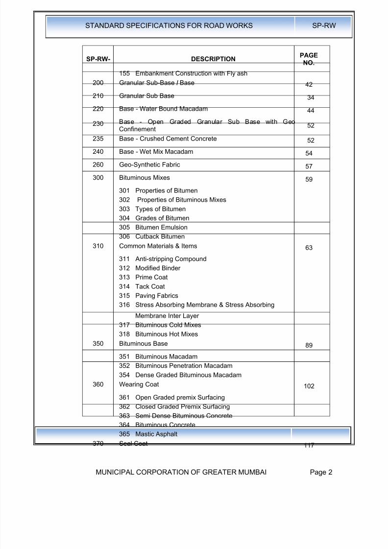
SP-RW- DESCRIPTIONPAGENO.
155 Embankment Construction with Fly ash
200 Granular Sub-Base I Base42
210 Granular Sub Base 34
220 Base - Water Bound Macadam 44
230 Base - Open Graded Granular Sub Base with GeoConfinement
52
235 Base - Crushed Cement Concrete 52
240 Base - Wet Mix Macadam 54
260 Geo-Synthetic Fabric 57
300 Bituminous Mixes 59
301 Properties of Bitumen
302 Properties of Bituminous Mixes
303 Types of Bitumen
304 Grades of Bitumen
305 Bitumen Emulsion
306 Cutback Bitumen
310 Common Materials & Items 63
311 Anti-stripping Compound312 Modified Binder
313 Prime Coat
314 Tack Coat
315 Paving Fabrics
316 Stress Absorbing Membrane & Stress Absorbing
Membrane Inter Layer
317 Bituminous Cold Mixes
318 Bituminous Hot Mixes
350 Bituminous Base89
351 Bituminous Macadam
352 Bituminous Penetration Macadam
354 Dense Graded Bituminous Macadam
360 Wearing Coat 102
361 Open Graded premix Surfacing
362 Closed Graded Premix Surfacing
363 Semi Dense Bituminous Concrete
364 Bituminous Concrete
365 Mastic Asphalt370 Seal Coat 117
8/19/2019 MCGM Road Spec Volume -II
http://slidepdf.com/reader/full/mcgm-road-spec-volume-ii 7/176
STANDARD SPECIFICATIONS FOR ROAD WORKS SP-RW
MUNICIPAL CORPORATION OF GREATER MUMBAI Page 3
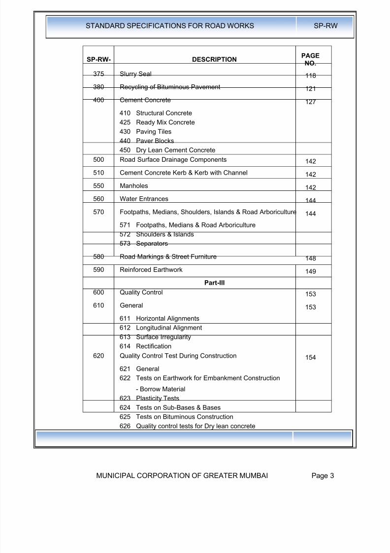
SP-RW- DESCRIPTIONPAGENO.
375 Slurry Seal 118
380 Recycling of Bituminous Pavement 121
400 Cement Concrete 127
410 Structural Concrete
425 Ready Mix Concrete
430 Paving Tiles
440 Paver Blocks
450 Dry Lean Cement Concrete
500 Road Surface Drainage Components 142
510 Cement Concrete Kerb & Kerb with Channel 142550 Manholes 142
560 Water Entrances 144
570 Footpaths, Medians, Shoulders, Islands & Road Arboriculture 144
571 Footpaths, Medians & Road Arboriculture
572 Shoulders & Islands
573 Separators
580 Road Markings & Street Furniture 148
590 Reinforced Earthwork 149
Part-III
600 Quality Control 153
610 General 153
611 Horizontal Alignments
612 Longitudinal Alignment
613 Surface Irregularity
614 Rectification
620 Quality Control Test During Construction 154
621 General
622 Tests on Earthwork for Embankment Construction
- Borrow Material
623 Plasticity Tests
624 Tests on Sub-Bases & Bases
625 Tests on Bituminous Construction
626 Quality control tests for Dry lean concrete
8/19/2019 MCGM Road Spec Volume -II
http://slidepdf.com/reader/full/mcgm-road-spec-volume-ii 8/176
STANDARD SPECIFICATIONS FOR ROAD WORKS SP-RW
MUNICIPAL CORPORATION OF GREATER MUMBAI Page 4
MCGM
Technical Specifications for Roads
10 Interpretations & Abbreviations
Interpretations
Order of Priority
Specifications indicated in BOQ
Technical Specifications outlined in MCGM Standard SpecificationsDrawings
Specifications of MORT & H - Latest Edition till 30 days before the finaldate of submission of the tender
Indian Road Congress Specifications - Latest Edition till 30 days before
the final date of submission of the tender
Bureau of Indian Standard Specifications - Latest Edition till 30 daysbefore the final date of submission of the tender
British Standard Specifications - Latest Edition till 30 days before the finaldate of submission of the tender
The Asphalt Institute, U.S.A. Publication of Specifications - Latest Editiontill 30 days before the final date of submission of the tender
11 Abbreviations
AASHTO : American Association of State Highway and TransportationOfficials
ASTM : American Society for Testing and Materials
BS : British Standard published by the British Standards Institution
BOQ : Bill of Quantities forming part of the contract
CBR: California Bearing Ratio
IRC : Indian Road Congress
IS : Indian Standard published by the Bureau of Indian Standards
WC : Water Cement Ratio
CRRI : Central Road Research Institute
UCS : Unconfined Compressive Strength
WBM : Water Bound Macadam
SAM: Stress Absorbing Membrane
SAMI : Stress Absorbing Membrane Interlayer
MoRTH: Ministry of Road Transport and Highways
8/19/2019 MCGM Road Spec Volume -II
http://slidepdf.com/reader/full/mcgm-road-spec-volume-ii 9/176
STANDARD SPECIFICATIONS FOR ROAD WORKS SP-RW
MUNICIPAL CORPORATION OF GREATER MUMBAI Page 5
20.0 New Technologies I Materials
20.1 New Technologies I Materials are the one that are not incorporated in this orMoRTH Standard Specifications
New technologies can make use of Newly Invented / patented materials,equipment or machinery. It can also make use of conventional materials /equipment with innovative design. In case of New Patented Material a warranteefrom the manufacturer! Contractor for three years and certification from twoInstitute like Central Road Research Institute, Indian Institute of Technology for itsacceptance for field application shall be essential. In case of innovative designs, itis essential for the contractor to indemnify the corporation against loss due tofailure in addition to certification from an Institute like Central Road ResearchInstitute(CRRI).
20.2 The Engineer, on satisfactory completion of above formalities, will allot a suitablestretch of road for mock up purposes. Its performance shall be monitored by the
Engineer and Quality Control Cell for one year. Based on the performance, adecision will be taken regarding qualification of the material design for fieldapplication. The successful performance will qualify Technology Materials to beincorporated as provisional specifications as alternative to these standardspecifications. The product shall be under observation for five years during whichits performance shall be monitored. On successful completion of the period withextensions, if any, the product shall be included in the Standard Specifications.
20.3 Measurements & Payment
The unit of measurements shall be as per mutual agreement between thecontractor and the Engineer.
20.4 Rate
The rate shall be derived from data given by the supplier / contractor.30.0 Arrangement for Traffic During Construction
30.1 General: The Contractor shall at all time carry out work on the roads in a mannercreating least interference to the flow of traffic while consistent with thesatisfactory execution of the same. For all works involving improvements to theexisting roads, the Contractor shall, in accordance with the directives of theEngineer, provide and maintain, during execution of the work, a passage fortraffic either along a part of the existing carriageway under improvement, oralong a temporary diversion constructed close to the roads. The Contractor shalltake prior approval of the Engineer regarding traffic arrangements duringconstruction.
30.2 Passage of Traffic along a part of the Existing Carriageway under Improvement:For widening / strengthening existing carriageway where part width of theexisting carriageway is proposed to be used for passage of traffic, treatedshoulders shall be provided on the side on which work is not in progress. Thetreatment to the shoulder shall consist of providing at least 150mm thick granularbase course covered with bituminous surface dressing in a width of at least 1.5mand the surface shall be maintained throughout the period during which trafficuses the same to the satisfaction of the Engineer.
In case of widening existing two-lane to four-lane, the additional two lanes wouldbe constructed first and the traffic diverted to it and only thereafter the requiredtreatment to the existing carriageway would be carried out. However, in casewhere on the request of the Contractor, work on existing two-lane carriageway isallowed by the Engineer with traffic using part of the existing carriageway,stipulations as in Para above shall apply. After obtaining permission of the

8/19/2019 MCGM Road Spec Volume -II
http://slidepdf.com/reader/full/mcgm-road-spec-volume-ii 10/176
STANDARD SPECIFICATIONS FOR ROAD WORKS SP-RW
MUNICIPAL CORPORATION OF GREATER MUMBAI Page 6
Engineer, the treated shoulder shall be dismantled, the debris disposed of andthe area cleared as per the direction of the Engineer.
30.3 Passage of Traffic along a Temporary Diversion: In stretches where it is notpossible to pass the traffic on apart width of the carriageway, a temporary
diversion shall be constructed with 7m carriageway and 2.5m earthen shoulderson each side (total width of roadway 12m) with the following provision for roadcrust in the 7m width:
i. 200mm (compacted) granular sub base;
ii. 225mm (compacted) granular base course; and
iii. Premix carpet with Seal Coat / Mix Seal Surfacing.
The alignment and longitudinal section of diversion including junctions andtemporary cross drainage provision shall be as approved by the Engineer.
30.4 Traffic Safety and Control: The Contractor shall take all necessary measures forthe safety of traffic during construction and provide, erect and maintain suchbarricades, including signs, markings, flags, lights and flagmen as may be
required by the Engineer for the information and protection of traffic approachingor passing through the section of the highway under improvement. Before takingup any construction, an agreed phased programme for the diversion of traffic onthe highway shall be drawn up in consultation with the Engineer.
The barricades erected on either side of the carriageway / portion of thecarriageway closed to traffic, shall be of strong design to resist violation, andpainted with alternate black and white stripes. Red lanterns or warning lights ofsimilar type shall be mounted on the barricades at night and kept lit throughoutfrom sunset to sunrise. At the points where traffic is to deviate from its normalpart (whether on temporary diversion or part width of the carriageway) thechannel for traffic shall be clearly marked with the aid of pavement markings,painted drums or a similar device to the directions of the Engineer. At night, thepassage shall be delineated with lanterns or other suitable light source. One-waytraffic operation shall be established whenever the traffic is to be passed overpart of the carriageway inadequate for two-lane traffic. This shall be done withthe help of temporary traffic signals or flagmen kept positioned on opposite sidesduring all hours. For regulation of traffic, the flagmen shall be equipped with redand green flags and lanterns / lights.
On both sides, suitably regulatory / warning signs as approved by the Engineershall be installed for the guidance of road users. On each approach, at least twosigns shall be put up, one close to the point where transition of carriagewaybegins and the other 120m away. The signs shall be of approved design and ofreflectory type, if so directed by the Engineer.
30.5 Maintenance of Diversions and Traffic Control Devices: Signs, lights, barriersand other traffic control devices, as well as the riding surface of diversions shallbe maintained in a satisfactory condition till such time they are required asdirected by the Engineer. The temporary travelled way shall be kept free of dustby frequent applications of water, if necessary. Wardens for monitoring traffic asper requirement of traffic police shall be provided by the contractor at his owncost.
30.6 The minimum curing time required during which the traffic is to be kept off thesurface for different types of layers / materials shall be as mentioned below:
a) Cement / Lime Stabilised Surfaces: Seven Days
b) Earthen Embankment: One Day
c) Granular Layer: Three Days
8/19/2019 MCGM Road Spec Volume -II
http://slidepdf.com/reader/full/mcgm-road-spec-volume-ii 11/176
STANDARD SPECIFICATIONS FOR ROAD WORKS SP-RW
MUNICIPAL CORPORATION OF GREATER MUMBAI Page 7
d) Bituminous Cold Mixes / Seal Coat : Twelve Hours for heavy vehicles andEight hours for light vehicles.
e) Bituminous Hot Mixes: Twenty Four Hours for heavy vehicles and eighthours for light vehicles
f) Slurry Seals: Four Hours30.7 Measurements for Payment and Rate: All arrangements for traffic during
construction including provision of temporary cross drainage structures, ifrequired, and treated shoulder as described in clause 30.2 including theirmaintenance, dismantling and clearing debris, where necessary, shall beconsidered as incidental to the works and shall be the Contractor's responsibility.
The construction of temporary diversion including temporary cross drainagestructures as described in clause 30.3 shall be measured in linear metre and theunit contract rate shall be inclusive of full compensation for construction(including supply of material, labour, tools, etc.), maintenance, final dismantling,and disposal.
40.0 Precautions for Safeguarding the Environment:40.1 General: The Contractor shall take all precautions for safeguarding the
environment during the course of the construction of the works. He shall abide byall laws, rules and regulations in force governing pollution and environmentalprotection that are applicable in the area where the works are situated.
40.2 Borrow pits for Embankment Construction: Borrow pits shall not be dug in theright-of-way of the road.
40.3 Quarry Operations: The Contractor shall obtain materials form quarries only afterthe consent of the Forest Department or other concerned authorities is obtained.The quarry operations shall be undertaken within the purview of the rules andregulations in force.
40.4 Control of Soil Erosion, Sedimentation and Water Pollution: The Contractor shallcarry out the works in such a manner that soil erosion is fully controlled, andsedimentation and pollution of natural water courses, ponds, tanks andreservoirs are avoided. The stipulations in Clause 306 of MORT&H.Specifications shall govern.
40.5 Pollution from Hot-Mix Plants and Batching Plants: Bituminous hot-mix plantsand concrete batching plants shall be located sufficiently away from habitation,agricultural operations or industrial establishments. The Contractor shall takeevery precaution to reduce the levels of noise, vibrations, dust and emissionsfrom his plant and shall be fully responsible for any claims for damages causedto the owners of property, fields and residences in the vicinity.
40.6 Substances Hazardous to Health: The Contractor shall not use or generate anymaterials in the works which are hazardous to the health of persons, animals orvegetation. Where it is necessary to use some substances which can causeinjury to the health of workers, the Contractor shall provide protective clothing orappliances to his workers.
40.7 Use of Nuclear Gauges: Nuclear gauges shall be used only where permitted bythe Engineer. The nuclear gauges shall be calibrated as per the conditions laiddown in the contract document. The Contractor· shall provide the Engineer with acopy of the regulations governing the safe use of nuclear gauges he intends toemploy and shall abide by such regulations.
40.8 The Contractor must take all reasonable steps to minimize dust nuisance during
the construction of the works.
8/19/2019 MCGM Road Spec Volume -II
http://slidepdf.com/reader/full/mcgm-road-spec-volume-ii 12/176
STANDARD SPECIFICATIONS FOR ROAD WORKS SP-RW
MUNICIPAL CORPORATION OF GREATER MUMBAI Page 8
40.9 All existing roads used by vehicle of the Contractor or any of his subcontractorsor suppliers of materials or plant, and similarly any new roads which are part ofthe works and which are being used by traffic, shall be kept clean and clear of alldust/mud or other extraneous materials dropped by the said vehicles or theirtyres. Similarly, all dust/mud or other extraneous materials from the worksspreading on these roads shall be immediately cleared by the Contractor.
40.10 Clearance shall be effected immediately by manual sweeping and removal ofdebris, or if so directed by the Engineer, by mechanical sweeping and clearingequipment, and all dust, mud and other debris shall be' removed entirely from theroad surface. Additionally, if so directed by the Engineer, the road surface shallbe hosed or watered using suitable equipment.
40.11 Any structural damage caused to the existing roads by the Contractor'sconstruction equipment shall be made good without any extra cost.
40.12 Compliance with the foregoing will not relieve the Contractor of any responsibilityfor complying with the requirements of any Authority in respect of the roads usedby him.
50.0 Site Details
53.0 Site Information:
53.1 The information about the site of work and site conditions in the TenderDocuments is given in good faith for guidance only but the Contractor shallsatisfy himself regarding all aspects of site conditions.
53.2 The location of the works and the general site particulars are as generally shownon the Site plan I Index plan enclosed with the Tender Documents.
53.3 Whereas the right-of-way to the bridge sites I road works shall be provided to theContractor by the Engineer, the Contractor shall have to make his ownarrangement for the land required by him for site offices, labour camps, stores,
etc.54.0 Setting Out:
54.1 The Contractor shall establish working Bench Marks related with the Town HallReference Bench Mark (THD) in the area soon after taking possession of thesite. The Reference Bench Mark for the area shall be as indicated. The workingBench Marks shall be at the rate of four per km and also at or near all drainagestructures, over-bridges and underpasses. The working Bench Marks I levelsshould be got approved from the Engineer. Checks must be made on theseBench Marks once every month and adjustments, if any, got agreed with theEngineer and recorded. An up-to-date record of all Bench Marks includingapproved adjustments, if any, shall be maintained by the Contractor and also acopy supplied to the Engineer for his record.
54.2 The lines and levels of formation, side slopes, drainage works, carriageways andshoulders shall be carefully set out and frequently checked, care being taken toensure that correct gradients and cross-sections are obtained everywhere.
54.3 In order to facilitate the setting out of the works, the centre line of thecarriageway or road must be accurately established by the Contractor andapproved by the Engineer. it must then be accurately referenced in a mannersatisfactory to the Engineer, every 50m intervals in plain and rolling terrains and20m intervals in hilly terrain and in all curve points as directed by the Engineer,with marker pegs and chainage boards set in or near the fence line, and aschedule of reference dimensions shall be prepared and supplied by theContractor to the Engineer. These markers shall be maintained until the works
reach finished formation level and are accepted by the Engineer.

8/19/2019 MCGM Road Spec Volume -II
http://slidepdf.com/reader/full/mcgm-road-spec-volume-ii 13/176
8/19/2019 MCGM Road Spec Volume -II
http://slidepdf.com/reader/full/mcgm-road-spec-volume-ii 14/176
STANDARD SPECIFICATIONS FOR ROAD WORKS SP-RW
MUNICIPAL CORPORATION OF GREATER MUMBAI Page 10
Contractors programme must take into account the period of notice and durationof diversionary works of each body as given on the Drawings and: the Contractormust also allow for any effect of these services and alterations upon the Worksand for arranging regular meetings with the various bodies at thecommencement of the Contract and throughout the period of the Works in orderto maintain the required co-ordination. During the period of the Works, theContractor shall have no objection if the public utility bodies vary their decisionsin the execution of their proposals in terms of programme and construction,provided that, in the opinion of the Engineer, the Contractor has receivedreasonable notice thereof before the relevant alterations are put in hand.
55.3 No clearance or alterations to the utility shall be carried out unless speciallyordered by the Engineer.
55.4 Any services affected by the Works must be temporarily supported by theContractor who must also take all measures reasonably required by the variousbodies to protect their services and property during the progress of the Works.
55.5 The Contractor may be required to carry out certain works for and on behalf of
the various bodies and he shall also provide, with the prior approval of theEngineer, such assistance to the various bodies as may be authorized by theEngineer.
55.6 The work of temporarily supporting and protecting the public utility servicesduring execution of the Works shall be deemed to be the part of the Contract andno extra payment shall be made for the same.
55.7 The Contractor may be required to carry out the removal or shifting of certainservices I utilities on specified orders from the Engineer for which payment shallbe made to him. Such works shall be taken up by the Contractor only afterobtaining clearance from the Engineer and ensuring adequate safety measures.
56.0 Methodology and Sequence of Work
56.1 Prior to start of the construction activities at site, the Contractor shall, within 15days after the date of the Letter of Acceptance, submit to the Engineer forapproval, the detailed construction methodology including mechanical equipmentproposed to be used, sequence of various activities and schedule from start toend of the project. Programme relating to pavement and shoulder from start toend of the project. Programme relating to pavement and shoulder constructionshall be an integrated activity to be done simultaneously in a co-ordinatedmanner. The methodology and the sequence shall be so planned as to provideproper safety, drainage and free flow of traffic.
57.0 Approval of Materials
57.1 Approval of all sources of material for work shall be obtained in writing from the
Engineer before their use on the project.58.0 Use bf Surfaces by Construction Traffic
Ordinarily, no construction traffic shall be allowed on pavement underconstruction unless authorized by the Engineer. Even in that case the load andintensity of construction traffic should be so regulated that no damage is causedto the sub-grade or pavement layers already constructed. Where necessaryservice roads shall be constructed for this purpose and the same shall beconsidered as incidental to the work.
The wheels or tracks of plant moving over the various pavement courses shall bekept free of deleterious materials.
Bituminous base course shall be kept clean and uncontaminated as long as thesame remains uncovered by a wearing course or surface treatment. The onlytraffic permitted access to the base course shall be that engaged in laying and
8/19/2019 MCGM Road Spec Volume -II
http://slidepdf.com/reader/full/mcgm-road-spec-volume-ii 15/176
STANDARD SPECIFICATIONS FOR ROAD WORKS SP-RW
MUNICIPAL CORPORATION OF GREATER MUMBAI Page 11
compacting the wearing course or that engaged on such surface treatmentwhere the base-course is to be blinded and I or surface dressed. Should thebase course or tack coat on the base course become contaminated, theContractor shall make good by clearing it to the satisfaction of the Engineer, andif this is impracticable, by removing the layer and replacing it to Specificationwithout any extra cost.
60.0 Measurements & Rates
61.0 General Rules for the Measurement of Works for Payment
61.1 General: All measurements shall be made in the metric system. Different items ofwork shall be measured in accordance with the procedures set forth in therelevant sections read in conjunction with the General Conditions of Contract.The same shall not, however, apply in the case of lump sum contracts.
All measurements and computations, unless otherwise indicated, shall be carriednearest to the following limits:
a) length and breadth 10mm
b) height, depth or thickness of earthwork, 5mmsub-grade, sub-bases, bases, surfacing
and structural members
c) areas 0.01 Sq. M.
d) cubic contents 0.01 Cu. M.
In recording dimensions of work, the sequence of length, width and height ordepth or thickness shall be followed.
61.2 Measurement of Lead for Materials: Where lead is specified in the Contract forconstruction materials, the same shall be measured as described hereunder:
Lead shall be measured over the shortest practicable route and not the one
actually taken and the decision of the Engineer in this regard shall be taken asfinal. Distances upto and including 100m shall be measured in units of 50m,exceeding 100m but not exceeding 1 Km. in units of 100m and exceeding 1 Km.in units of 500m, the half and greater than half of the unit shall be reckoned asone and less than half of the unit ignored. In this regard, the source If materialshall be divided into suitable blocks and for each block, the distance from thecentre of the block to the centre of placing pertaining to that block shall be takenas the lead distance.
61.3 Measurement of Pavement Thickness for Payment on Volume Basis: Thefinished thickness of sub-base, base and bituminous courses to be paid onvolume basis shall be computed in the following manner:
Levels shall be taken before and after construction, at grid of points 10m centreto centre longitudinally in straight reaches but 5m at curves. Transverse levelsshall be taken at an interval of 2 / 2.5 M as directed by the Engineer.
Suitable references for the transverse grid lines should be left in the form ofembedded bricks on either ends or by other means so that it is possible to locatethe grid points for level measurements after each successive course is laid. Forpavement courses laid only over widening portions, at least one line of levelsshall be taken on each strip of widening, or more depending on the width ofwidening as decided by the Engineer.
Notwithstanding the above, the measurements may be taken at closer intervalsalso, if so desired by the Engineer, the need for which may arise particularly inthe case of estimation of the volume of the material for profile corrective course(levelling course). The average thickness of the pavement course in any areashall be the arithmetic mean of the difference of levels before and after
8/19/2019 MCGM Road Spec Volume -II
http://slidepdf.com/reader/full/mcgm-road-spec-volume-ii 16/176
STANDARD SPECIFICATIONS FOR ROAD WORKS SP-RW
MUNICIPAL CORPORATION OF GREATER MUMBAI Page 12
construction at all the grid points falling in that area, provided that the thicknessof finished work shall be limited to those shown on the drawings or approved bythe Engineer in writing.
As supplement to level measurements, the Engineer shall have the option to take
cores/make holes to check the depth of construction. The holes made and theportions cut for taking cores shall be made good by the Contractor by layingfresh mix / material including compacting as required at no extra costimmediately after the measurements are recorded.
61 .4 Checking of Pavement Thickness for Payment on Area Basis : Where paymentfor any bituminous course in Section 300 is allowed to be made on area basis,the Engineer may have its thickness checked with the help of a suitablepenetration gauge at regular intervals or other means as he may decide.
61.5 Measurement of Bituminous Courses for Payment on Weight Basis: Plant-mixedbituminous materials for pavement courses where designated to be paid onweight basis shall be weighed on accurate scales approved by the Engineer. Approved scales shall mean scales that area of size, capacity, kind and type
suitable for the weighing to be done, and these shall be properly and adequatelyinstalled and maintained. Prior to the use of the scales and as frequentlythereafter as the Engineer may deem necessary to ensure accuracy, the scalesshall be checked and approved by the Engineer, or the Engineer may direct theContractor to have the scales checked by other competent agency at the cost ofthe Contractor.
Location of the scales shall be as designated by the Engineer. Trucks used forhauling the material to be weighed shall be weighed empty daily at such times asthe Engineer directs, and each truck shall bear a plainly legible identificationmark.
For materials specified to be measured by weight, the Engineer will have the
option to make measurements of the finished work by volume and such volumesshall be converted into weight for payment purposes. The factor for conversionfrom volume measurement to weight measurement shall be computed from therepresentative density of the compacted material at site determined at locationsapproved by the Engineer.
62.0 Scope of Rates for Different Items of Work
For ·item rate contracts, the contract unit rates for different items of work shall bepayment in full for completing the work to the requirements of the Specificationsincluding full compensation for all the operations detailed in the relevant sectionsof these Specifications under "Rates". In the absence of any directions to thecontrary, the rates are to be considered as the full inclusive rate for finished work
covering all labour, materials, wastage, temporary work, plant, equipment,overhead charges and profit as well as the general liabilities, obligations,insurance and risks arising out of General Conditions of Contract.
The item rates quoted by the Contractor shall, unless otherwise specified, alsoinclude compliance with I supply of the following:
a) General works such as setting out, clearance of site before setting out andclearance of works after completion,
b) A detailed programme for the construction and completion of the work(using CPM/PERT techniques) giving, in addition to construction activities,detailed network activities for the submission and approval of materials,procurement of critical materials and equipment, fabrication of special
products I equipment and their installation and testing, and for all activitiesof the Employer that are likely to affect the progress of work, etc. including
8/19/2019 MCGM Road Spec Volume -II
http://slidepdf.com/reader/full/mcgm-road-spec-volume-ii 17/176
STANDARD SPECIFICATIONS FOR ROAD WORKS SP-RW
MUNICIPAL CORPORATION OF GREATER MUMBAI Page 13
updating of all .such activities on the basis of the decisions taken at theperiodic site review meetings or as directed by the Engineer;
c) Samples of various materials proposed to be used on the Work forconducting tests thereon as required as per the provisions of the Contract;
d) Design of mixes as per the relevant Clauses of the Specifications givingproportions of ingredients, sources of aggregates and binder along withaccompanying trial mixes as per the relevant Clauses of theseSpecifications to be submitted to the Engineer for his approval before useon the Works;
e) Detailed design calculations and drawings for all Temporary Works (suchas formwork, staging, centering; specialized constructional handling andlaunching equipment and the like);
f) Detailed drawings for templates, support and end anchorage, details of pre-stressing cable profiles, bar bending and cutting schedules forreinforcement, material lists for fabrication of structural steel, etc;
g) Mill test reports for all mild and high tensile steel and cast steel as per therelevant provisions of the Specifications;
h) Testing of various finished items and materials including bitumen, cement,concrete, bearings as required under these Specifications and furnishingtest reports/certificates;
i) Inspections Reports in respect of formwork, staging, reinforcement andother items of work as per the relevant Specifications;
j) Any other date which may be required as per these Specifications for theConditions of Contract or any other annexures / schedules forming part ofthe contract;
k) Any other item of work which is not specifically provided in the Bill of
Quantities but which is necessary for complying with the provisions of theContract;
I) All temporary works, formwork and false work;
m) Establishing and running a laboratory with facilities for testing for variousitems of works as specified in Section 600 and other relevant Clauses,where there is no separate item in the Bill of Quantities for establishing andrunning a laboratory;
n) Cost of in-built provisions for Quality Assurance;
o) Cost of providing "as-built drawings" in original and two sets of prints andC.D.
Portions of road works beyond the limits and / or any other work may be gotconstructed by the Employer directly through other agencies. Accordingly, otheragencies employed by the Employer may be working in the vicinity of the Worksbeing executed by the Contractor. The Contractor shall liaise with such agenciesand adjust his construction programme for the completion of work accordinglyand no claim or compensation due to any reason whatsoever will be entertainedon this account. The Employer will be indemnified by the Contractor for anyclaims from other agencies on this account.

8/19/2019 MCGM Road Spec Volume -II
http://slidepdf.com/reader/full/mcgm-road-spec-volume-ii 18/176
STANDARD SPECIFICATIONS FOR ROAD WORKS SP-RW
MUNICIPAL CORPORATION OF GREATER MUMBAI Page 14
100.0 Road and Drainage Excavation
101.0 Description :
Roadway and drainage excavation shall consist of excavation removal and satisfactorydisposal of all excavated materials and necessary for the requirements of thosespecifications and in the lines, grades and cross-sections shown on the drawingsof indicated by the by the engineer. This work shall include the hauling andstacking or of hauling to sites of embankment construction of suitable cutmaterials as required, as also the disposal of unsuitable cut materials in specifiedmanner and the trimming and finishing of the road way.
102.0 Classification of excavations: All materials involved in excavation shall beclassified by engineer either under two groups as 102.1 and 102.2 or as per subclasses of these groups as stated in the contract.
102.1 General Classification: This shall comprise of excavation in soils, road metal,made ground, clays, moorum, boulders, sand, masonry or concrete infoundation, plinths and walls and all other material including whatever descriptionnot requiring to be blasted.
102.1.1 Soil
This shall comprise of topsoil, sand, silt, loam, clay, mud, marine clay, loosemoorum, or similar material which yields to the ordinary application of pick,spade and / or shovel. Removal of gravel or any other nodular material havingdimension not exceeding 75 mm occurring in such strata shall be deemed to becovered.
102.1.2 Soft rock
This shall include : Macadam surfaces, soling or hard core of roads, stabilised
soil, compact moorum gravel, cobble stone having maximum dimension between75 & 300 mm, masonry work, concrete , boulders etc which can be removed withJCB.
102.1.3 Marshy Soil
This shall include soils like marine clays, peats below original levels of marshesand swamps requiring continuous pumping or bailing out of water
102.2 Rock Excavation: This shall comprise of rock, big boulders more than 0.25cubic meters (8 c ft). In volume, very hard stone or littoral concrete or anymaterial requiring to be blasted by an explosive or broken into small pieces byiron wedges or chisels. The rock excavation shall have two classes
102.2.1 Rock Excavation by Blasting: This shall comprise boulders, hard rock, RCC,
cement concrete for excavation of which the use of blasting is required.102.2.2 Hard Rock (Blasting Prohibited): Due to restrictions, where excavation in rock
cannot be done by blasting and chiseling, weighing or mechanically chisels,pavement breakers·are required to be used.
102.3 In case of any question arising as the class of excavation, the engineer shalldetermine under which category and that to what extent any particularexcavation shall be classed.
103.0 Construction Operations:
103.1 After the site has been cleared, the limits of excavation shall be set out true lines,curves, slopes grades and sections as shown on the drawings or as directed byengineer. The Contractor shall provide all labour, survey instruments and
materials, such as strings pegs, nails, bamboo, stones, lime, mortar, concrete,etc. required in connection with the setting out of works and establishment of
8/19/2019 MCGM Road Spec Volume -II
http://slidepdf.com/reader/full/mcgm-road-spec-volume-ii 19/176
STANDARD SPECIFICATIONS FOR ROAD WORKS SP-RW
MUNICIPAL CORPORATION OF GREATER MUMBAI Page 15
bench marks. The Contractor shall be responsible for the maintenance of benchmarks and stokes as long as they are required for the work in the opinion of theEngineer.
103.2 Excavation-General: All excavation shall be carried out in conformity with the
directions laid here in under and in a manner approved by the engineer. Thework shall be so planned that the suitable materials available from excavationare satisfactorily utilised as decided upon of the Engineer.
The excavation shall conform to the lines, grades, side slopes and levels shownon the drawings or as directed by Engineer. The contractor shall not excavateoutside the slopes or below the established grades or loosen any materialoutside the limits of excavation. Subject to the permitted tolerances, any excessdepth excavated below the specified levels on the roadway shall be made goodat the cost of the contractor with suitable material of similar characteristics to thatremoved and compacted to the requirements of clause 150.
All debris and loose material on the slopes of cutting shall be removed. No backfilling shall be allowed to obtain required slopes except when boulders or soft
pockets are encountered in cut slopes these shall be excavated to approveddepth on instructions of the Engineer and regulating cavity filled with suitablematerial and thoroughly composted in as approved manner.
103.3 Rock Excavation:
103.3.1 Rock when encountered in roadway excavation, shall be removed upto thesubgrade level or as otherwise indicate on the drawings. Where howeverunstable material is intersected at the subgrade level, these shall be excavatedto the extent of 500mm below the subgrade level or as otherwise specified. In allcases, the excavation operation shall be so carried out that at no point on cutfoundation the rock protrudes above the specified levels, provides however that anegative tolerance of 150 mm shall be permissible.
Where excavation is done to levels lower than this specified, the excessexcavation shall be made good by hand packing with rubble and chips todesignate level and compacting to the satisfaction of the Engineer.
Slopes in rock cuttings shall be finished to uniform lines corresponding to slopelines shown on the drawing or as directed by the Engineer. Notwithstanding theforegoing all loose pieces of rock on excavated slope surface, which move whenprised by a crow bar, shall be removed.
Where blasting is to be resorted to, the same shall be carried out to clause103.3.2 and precautions indicated there in observed.
103.3.2 Blasting:
103.3.2.1 Blasting shall not be done without the previous consent of the Engineer and shallbe restricted to the hours which he may prescribe. If in the opinion of theEngineer, blasting would be dangerous to persons or adjacent structure, or isbeing carried on in a reckless manner, the rock shall be excavated by othermeans.
103.3.2.2 Storage of Explosives: The contractors shall obtain the previous permission ofthe Chief of Fire Services for the site, manner and method of storing explosivesnear the sites of works. All handlings of explosives, including storage andtransporting shall be carried out under the rules approved by the ExplosivesDepartment of the Government.
103.3.2.3 In carrying out rock blasting, the Contractors shall take all necessary precautionby the use of screens weighted down and other means for the protection of life
and property and shall strictly comply with all rules and regulations that may belaid down by the Commissioner of Police, by the Engineer or by other regularly

8/19/2019 MCGM Road Spec Volume -II
http://slidepdf.com/reader/full/mcgm-road-spec-volume-ii 20/176
STANDARD SPECIFICATIONS FOR ROAD WORKS SP-RW
MUNICIPAL CORPORATION OF GREATER MUMBAI Page 16
constituted authority having jurisdictions relative to handling, storing and use ofexplosive.
103.3.2.4 In order to ensure the safety of surrounding property and persons no chargeshall be used which is larger than necessary properly to start the work and rock
excavation contiguous to any structure shall be carried on so as not to causedamage to such structure.
103.4 Marsh Excavation: The excavation of marshes \ swamps \ waterlogged areasshall be carried out to clause as per the programme laid down by the Engineer.The Excavation of such portions shall begin at one end and proceed in onedirection across the entire marsh immediately ahead of back filling. The methodand sequence of excavating and back filling shall be such as to assure , to theextend practicable , the complete removal or displacement of all muck fromwithin the lateral limits called for on the drawings or as directed by the Engineerand to the bottom of the marsh, firm support or Levels indicated
103.5 Excavation of Road shoulders for widening pavement: In works involvingwidening of existing pavements, unless otherwise specified the shoulders shall
be removed to their full width and to levels shown on the Drawing or as directedby the Engineer. While doing so, care shall be taken to see that, no portion of theexisting pavement, designated to retained, is loosened or distributed.
104.0 Dewatering: If water is met in the excavations due to springs, seepage, rain orother causes, it shall be removed by suitable diversions, pumping or baling outand the excavations kept dry whenever so required or directed by Engineer.Care shall be taken to discharge the drained water in such a manner as not to beretained, is loosened or distributed.
The contractors shall provide and work at their own cost all pumps engines andmachinery requisite to keep the trenches for the sewers, drains or foundation andother excavation clear of water, whether subsoil water, storm water or leakages
from tanks, wells, drains sewers of pipes so that there may be no accumulationsof such water and that no setting out may be done, no masonry may be laid, noconcretes deposited, no joints made no measurements taken the water. Thepumping shall be continued so long after execution of any portion of the workand repeated often as the Engineer may consider necessary. The pumps andpower applied must be such as the Engineer may determine to be sufficient atany particular time, or he may himself supply pumps and power at thecontractor's cost or he may stop the work altogether until he is satisfied and alsoimpose a fine upon the contractors. No nuisance shall be caused to the trafficand residents at the place due to the dewatering operations etc.
105.0 Disposal of Excavated Material:
105.1 All the excavated materials shall be the property of the Corporation.The excavated materials shall be utilised without any extra charge in forming thebank of the road as specified in that behalf or filling in trenches, low lying groundor wells or shall be deposited in such places and to such heights and levelled asthe Engineer may direct within a distance of 30 metres (100 Ft.) from any edge ofthe proposed road site in the contract.
If there be any stone in the excavated materials, suitable for rubble packing, roadmetal or for building or any other Municipal purposes, it shall be separated anddeposited as stated above, also without any extra charges.
If any excavation in the road metal or rubble packing be carried out in connectionwith pipes sewers, drains, manholes, etc. the road metal or the rubble packing
shall be first stripped of for the whole width of the trench and for the whole extentof the chamber required and separately deposited to be again utilized as the
8/19/2019 MCGM Road Spec Volume -II
http://slidepdf.com/reader/full/mcgm-road-spec-volume-ii 21/176
STANDARD SPECIFICATIONS FOR ROAD WORKS SP-RW
MUNICIPAL CORPORATION OF GREATER MUMBAI Page 17
Engineer may direct while the other material from the excavation shall bedisposed of a specified herein above or same, as may be necessary to preventthe weight of the materials from causing the sides of trench to slip or fall.
In case where the Engineer decides that the width of the road or lane where work
of excavation is to be carried out is so narrow as to warrant stacking excavatedmaterial away from the site of the work the contractors shall have to remove thesame if so directed within a lead of 300 metres (1000 Ft.). The excavated stuffshall be brought back from any edge of the proposed work site, for refilling thetrenches when required. The surplus material shall be removed as directed. Noclaims for stacking the excavated stuff away from the site of work or bringing itback for refilling trenches shall be entertained.
105.2 Disposal of Surplus Material : The surplus earth, stones, boulders and othermaterials that will be left after using them for embankments in filling in hollows,wells and rubble packing etc. within the limits of the work, shall be removed to aplace with the distance quoted in tenders and as directed by the Engineer. Therate for removal of surplus material to any given place, shall include fencing and
lighting at site, loading and unloading spreading in layers not more than 25cms(10") thick at dumping ground or stacking in depots of suitable sizes whereverrequired, as directed by the Engineer. It must be thoroughly understood that thisshall be paid upon the quantity of space, the material will occupy after excavationand also after deducting the quantity of earth that may have been used on workfor filing in embankment hollows, wells, and other low lying grounds within thelimits of the work. This shall also include the removal of surplus material fromtrenches taken by any Public utility company or by other department of theMunicipal Corporation.
106.0 Preservation of Property:
106.1 The contractor shall take all reasonable precautions for the protection and
preservations of any or all existing road side trees, drains, sewers or othersubsurface drains pipes, conducts and any other structure under or aboveground, which may be affected by constructions, operations and which in theopinion of the Engineer shall be continued in use without any charges.Safeguards taken by the contractors in this respect shall be got approved by himfrom the Engineer. However, if any of these objects is damaged by reason of thecontractor's negligence, it shall be replaced or restored to the original condition athis expense.
106.2 Precaution : If the work which the excavation shall have been made be notcompleted by the 20th day of May next following or the settling on of rain orbefore the day fixed by the Engineer for filling in any excavation on account ofthe Mohorrum, or Diwali or other holiday or of any special occasion or ceremony,
the contractors shall refill any such excavation or the Engineer may refill andcompact at their expenses, notwithstanding the non-completion of the work asaforesaid and in no such case shall the contractor have any claim for suchexcavation, refilling or compaction or for any such incomplete work but on theother hand, the contractors shall bear the cost of road repairs in respect of suchexcavations at such time, together with the cost of such procedure as may beadopted by the Engineer. The contractors may be permitted to continue to workup to 21 st May on sewers passing through open land or unpaved road or roadsnot carrying heavy traffic and wide enough to permit reinstatement being carriedout after setting in of rain without affecting traffic movement.
106.3 Lighting of Excavations : All excavations, trenches, obstructions, materials, etc.
taken, kept or deposited in connection with the work would be sufficiently lightedat night in order to guard against any damage or danger to the traffic and to take
8/19/2019 MCGM Road Spec Volume -II
http://slidepdf.com/reader/full/mcgm-road-spec-volume-ii 22/176
STANDARD SPECIFICATIONS FOR ROAD WORKS SP-RW
MUNICIPAL CORPORATION OF GREATER MUMBAI Page 18
all precautions to keep all the lamps lighted whole night for the guidance of thetraffic in the following manner:
106.4 All lamps must be kept at a height of about 1 m to 1.25m at strategic points.
a) All lamps should be red in colour.
b) All lamps across, the direction of traffic should be spaced at a distance of notmore than 2m apart.
c) The lamps along the line of traffic should be spaced not more than 9m to 15mapart.
d) To take such other measures as may be directed by the Engineer from time totime for the safety of the traffic.
e) The contractor shall make all proper provision for protecting the work byproviding portable traffic barricade with flashers otherwise known as Blinkers.Specification of Blinkers are as follows:
Series 6,100 blinker unit consisting of a solid state oscillator - dryer circuit usingsilicon transistors, tropicalised printed circuit card, driving a 2.4 watt filament
lamp in a screw holder. The unit contains four flashlight cells (type D, 1.5 V) in abattery compartment in the base. Removable bottom to facilitate quick batterychange.
The assembly is housed in a specially shaped handy box, MS fabricated, paintedin attractive traffic yellow with regulation strips on the visible base. Bakelitehandles on top for carrying. The sides fitted with pre-focused mouldedpolystyrene lenses red or amber having prismatic inner surface for efficient lighttransmission. Visibility approximately 150 metres on dark night.
106.5 In the event of the contractors not complying with the provisions of this clauses,the Engineer may without notice to the contractors put up the barricade orimprove upon the same or provide or improve the lighting to adopt such other
measures as he may deem necessary and all the cost of such procedure as maybe adopted by the Engineer shall be borne by the contractors shall be charged apenalty of Rs.100/- per day till compliance of this requirement.
107.0 Finishing Operations:
107.1 Finishing operations shall include the work of properly shaping and dressing allexcavated surfaces.
When completed, to point on the slopes shall vary from the designated slopes bymore than 150mm measured at right angles to the slope except whereexcavation is in rocks (hard or soft) where no point shall vary more than 600mmfrom the designated slope. In no case shall any portion of the slope encroach onthe roadway.
The finished cut formation shall satisfy the surface tolerances described inClause 610 & 620.
When directed, the top soil removed earlier and conserved, shall be spread overout slopes, berms and other disturbed areas. Slopes may be roughened andmoistened slightly, prior to the application of top soil, in order to providesatisfactory bond.
107.2 Laying of Sub-Grade (Preparation of Cut Formation):
The subsoil shall be levelled approximately to proper level and camber by fillingdepressions with excavated material and cutting off protuberances. The subsoilshall be made to have as nearly as practicable a uniform bearing power and allhard spots therefore be properly excavated and refilled.
All soft and spongy parts of the subsoil shall also be excavated and refilled withapproved materials in 15cm (6") layers for the same reason. (The cost of this
8/19/2019 MCGM Road Spec Volume -II
http://slidepdf.com/reader/full/mcgm-road-spec-volume-ii 23/176
STANDARD SPECIFICATIONS FOR ROAD WORKS SP-RW
MUNICIPAL CORPORATION OF GREATER MUMBAI Page 19
excavation will be paid after under the item for excavation). The subsoil shall bewatered adequately as directed before a roller as put on it. Proper accessesshould be prepared for the roller to get to the subsoil and all manholes framesand covers should be removed by plates free of cost whenever they interfacewith the free rolling of the subsoil.
After rolling, the camber super elevation and longitudinal slope etc. of the subsoilshall conform in shape to those of the finished road surface. This should bechecked with the help of level stakes, strings and camber board if necessary.
107.3 In rocky formations, the surface irregularities shall be corrected and the levelsbrought up to the specified elevation with granular base material as directed bythe Engineer, laid and compacted in accordance with the respectiveSpecifications for these materials. The unsuitable material shall be disposed of inaccordance with Clause 105.2. After satisfying the density requirements, the cutformation shall be prepared to receive the sub-base / base course in accordancewith Clauses 107.2 to receive the sub-base/base course.
108.0 Measurements & Rates
108.1 Works involved in the preparation of cut formation shall be measured in unitsindicated below:
i. Loosening and re-compacting the loosened material
at sub-grade. Cu. M.
ii. Loosening and removal of unsuitable material and
replacing with a suitable material and compacting
to required density Cu. M.
iii. Preparing rocky sub-grade Sq. M.
iv. Stripping including storing and reapplication of top soil Cu. M.
v. Disposal of surplus material beyond initial 1000m lead Cu. M.108.2 The rates for excavation shall be held to include and cover without extra charge
all the stipulations contained in every portion of clause with regard to shoring,pumping, shaping the trenches, filling grounds or embanking with the excavatedmaterials, or removing surplus materials, and separating stones suitable forMunicipal Work, maintenance of pipes, drain and other work, fencing, lighting,watching, ramming foundation and all matters and things connected with a orrendered necessary or otherwise involved by the excavation.
The excavation for the road work will be paid on the basis of sectionalmeasurements irrespective of the work.
In case of rock excavation, where cross-sectional measurements are not
possible due to irregular configuration or where the rock is admixed with otherclasses of materials, the volumes shall be computed on the basis of stacks ofexcavated rubble after making 40% deduction due to voids therein.
If in any place, the Engineer may consider that on account of the nature ofsubsoil, additional foundations of concrete, rubble otherwise are necessary, or ifin any place, he may require the excavation, for any purpose whatsoever, notshown on plans or described in the specification, the excavation shall be carriedout as may be ordered by the Engineer and such additional works shall bemeasured and paid for the contractors.
The disposal of surplus material shall be measured and paid extra or shall bepart of the excavation item as per the provisions of the Bill of Quantities.

8/19/2019 MCGM Road Spec Volume -II
http://slidepdf.com/reader/full/mcgm-road-spec-volume-ii 24/176
STANDARD SPECIFICATIONS FOR ROAD WORKS SP-RW
MUNICIPAL CORPORATION OF GREATER MUMBAI Page 20
108.2.1 The Contract unit rates for the items of roadway and drain excavation shall bepayment in full for carrying out the operations required for the individual itemsincluding full compensation for:
i. Setting out,
ii. Transporting the excavated materials and depositing the same on sites ofembankments, spoil banks or stacking as directed within all lifts and leadupto 1000 m or as otherwise specified,
iii. Trimming bottoms and slopes of excavation,
iv. Dewatering,
v. Keeping the work free of water
vi. All labour, materials, tools, equipment, safety measures, testing andincidentals necessary to complete the work to Specifications.
1082.1.1 The Contract unit rate for loosening and re-compacting the loosened materials atsub-grade, if provided separately in the contract, shall include full compensationfor loosening to the specified depth, including breaking clods, spreading in
layers, watering where necessary and compacting to the requirements.
108.2.1.2 Clauses 108.2.1, 153.2 and 153.3 shall apply as regards Contract unit rate foritem of removal of unsuitable material and replacement with suitable materialrespectively.
108.2.1.3 The Contract unit rate, if provided separately, for item of preparing rocky sub-grade as per Clause 107.2 shall be full compensation for providing, laying andcompacting granular base material for correcting surface irregularities includingall materials, labour and incidentals necessary to complete the work and all leadsand lifts.
108.2.1.4 The Contract unit rate, if provided separately, for the items of stripping and
storing topsoil and of reapplication of topsoil shall include full compensation forall the necessary operations including all lifts, but leads as stated in the contract.
108.2.1.5 The Contract unit rate, if separately provided in the contract, for disposal ofsurplus earth from roadway and drain excavation shall be full compensation forall labour, equipment, tools and incidentals necessary on account of theadditional haul or transportation involved beyond the initial lead provided in therespective item of excavation.
120.0 Sub-Surface Drains:
120.1 Scope: Sub-Surface drains shall be of close-jointed perforated pipes, open- jointed unperforated pipes, surrounded by granular material laid in a trench oraggregate drains to drain the pavement courses. Subsurface drains designed
using Geo-synthetics and approved by the Engineer can also be used.120.2 Materials:
120.3 Pipe : Perforated pipes for the drains may be of metal I asbestos cement Icement concrete I PVC, and unperforated pipes of I cement concrete I asbestoscement. The type, size and grade of the pipe to be used shall be as specified inthe Contract. In no case, however, shall the internal diameter of the pipe be lessthan 100mm. Holes for perforated pipes shall be on one half of the circumferenceonly and conform to the spacing indicated on the drawings. Size of the holesshall not ordinarily be greater than half of D85 size of the material surroundingthe pipe, subject to being minimum 3mm and maximum 6mm. D85 stands for thesize of the sieve that allows 85 per cent of the material to pass through it.
120.3.1 Backfill Material: Backfill Material shall consist of sound, tough, hard, durableparticles of free draining sand-gravel material or crushed stone and shall be free
8/19/2019 MCGM Road Spec Volume -II
http://slidepdf.com/reader/full/mcgm-road-spec-volume-ii 25/176
STANDARD SPECIFICATIONS FOR ROAD WORKS SP-RW
MUNICIPAL CORPORATION OF GREATER MUMBAI Page 21
of organic material, clay balls or other deleterious matter. Unless the Contractspecifies any particular grading for the backfill material or requires these to bedesigned on inverted filler criteria for filtration and permeability to the approval ofthe Engineer, the backfill material shall be provided on the following lines:
120.3.2 Where the soil met with in the trench is of fine grained type (e.g. silt, clay or amixture thereof), the backfill material shall conform to Class I grading set out inTable 100.1.
120.3.3 Where the soil met with in the trench is of coarse silt to medium sand or sandytype, the backfill material shall correspond to Class II grading of Table 100.1.
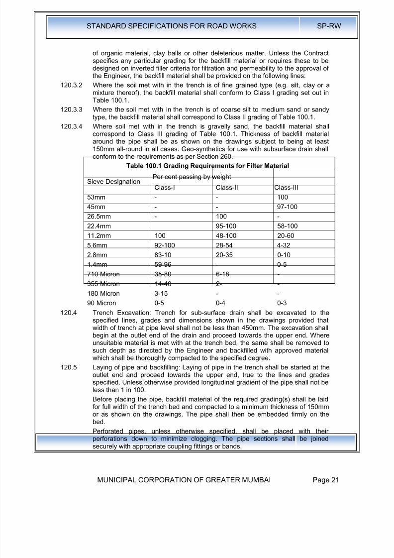
120.3.4 Where soil met with in the trench is gravelly sand, the backfill material shallcorrespond to Class III grading of Table 100.1. Thickness of backfill materialaround the pipe shall be as shown on the drawings subject to being at least150mm all-round in all cases. Geo-synthetics for use with subsurface drain shallconform to the requirements as per Section 260.
Table 100.1 Grading Requirements for Filter Material
Sieve Designation Per cent passing by weightClass-I Class-II Class-III
53mm - - 100
45mm - - 97-100
26.5mm - 100 -
22.4mm 95-100 58-100
11.2mm 100 48-100 20-60
5.6mm 92-100 28-54 4-32
2.8mm 83-10 20-35 0-10
1.4mm 59-96 - 0-5710 Micron 35-80 6-18 -
355 Micron 14-40 2- -
180 Micron 3-15 - -
90 Micron 0-5 0-4 0-3
120.4 Trench Excavation: Trench for sub-surface drain shall be excavated to thespecified lines, grades and dimensions shown in the drawings provided thatwidth of trench at pipe level shall not be less than 450mm. The excavation shallbegin at the outlet end of the drain and proceed towards the upper end. Whereunsuitable material is met with at the trench bed, the same shall be removed tosuch depth as directed by the Engineer and backfilled with approved materialwhich shall be thoroughly compacted to the specified degree.
120.5 Laying of pipe and backfilling: Laying of pipe in the trench shall be started at theoutlet end and proceed towards the upper end, true to the lines and gradesspecified. Unless otherwise provided longitudinal gradient of the pipe shall not beless than 1 in 100.
Before placing the pipe, backfill material of the required grading(s) shall be laidfor full width of the trench bed and compacted to a minimum thickness of 150mmor as shown on the drawings. The pipe shall then be embedded firmly on thebed.
Perforated pipes, unless otherwise specified, shall be placed with theirperforations down to minimize clogging. The pipe sections shall be joinedsecurely with appropriate coupling fittings or bands.

8/19/2019 MCGM Road Spec Volume -II
http://slidepdf.com/reader/full/mcgm-road-spec-volume-ii 26/176
STANDARD SPECIFICATIONS FOR ROAD WORKS SP-RW
MUNICIPAL CORPORATION OF GREATER MUMBAI Page 22
Non-perforated pipes shall be laid with joints as close as possible with the open joints wrapped with suitable pervious material (like double layer of Hessian,suitable Geo-synthetics or some other material of not less than 150mm width) topermit entry of water but prevent fines entering the pipe. In the case of non-perforated pipes with bell end, the bell shall face upgrade. Upgrade end sectionsof the pipe installation shall be tightly closed by means of concrete plugs or plugsfabricated from the same material as the pipe and securely held in place toprevent entry of soil materials.
After the pipe installation has been completed and approved, backfill material ofthe required grading(s) (see Clause 120.2.2) shall be placed over the pipe to therequired level in horizontal layers not exceeding 150mm in thickness andthoroughly compacted. The minimum thickness of material above the top of thepipe shall be 300mm.
Unless otherwise provided, sub-surface drains not located below the roadpavement shall be sealed at the top by means of 150mm thick layer ofcompacted clay so as to prevent percolation of surface water.
120.6 Use of Geo-synthetic in laying of pipe and backfilling: After excavating the trenchfor sub-surface drain, the filter fabric (Geo- Textile as per clause 262) shall beplaced, the pipe installed and the trench backfilled with permeable materialaccording to dimensions and details shown on the plans. Surfaces to receivefilter fabric prior to placing shall be free of loose of extraneous material and sharpobjects that may damage the filter fabric during installation. Adjacent rolls of thefabric shall be overlapped a minimum of 450mm. the preceding roll shall overlapthe following roll in the direction the material is being spread.
Damage to the fabric resulting from Contractor's vehicles, equipment oroperations shall be replaced or repaired by the Contractor at his expense.
120.7 Drain Outlet : The outlet for a sub-drain shall not be under water or plugged with
debris but should be a free outlet discharging into a stream, culvert or open ditch.The bottom of the pipe shall be kept above high water in the ditch and the endprotected with a grate or screen. For a length of 500mm from the outlet end, thetrench for pipe shall not be provided with granular material but backfilled withexcavated soil and thoroughly compacted so as to stop water directly percolatingfrom the backfill material around the pipe. The pipe in this section shall not haveany perforations.
120.8 Aggregate Drains: Aggregate Drains shall be placed within the verge / shouldersafter completion of the pavement. Depth, thickness and spacing of the aggregatedrains shall be as shown on the plan.
Trenches for aggregate drains shall be excavated to a minimum width of 300mm
and to the depth shown on the plans or ordered by the Engineer. The bottom ofthe trench shall be sloped to drain and shall be free from loose particles of soil.The trench shall be excavated so as to expose clearly the granular pavementcourses to be drained.
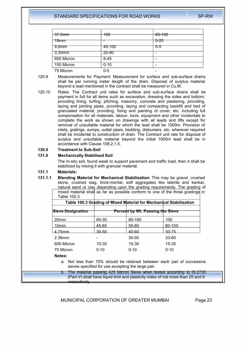
Aggregate for the drains shall be durable gravel, stone or slag and shall be freefrom vegetable matter and other deleterious substances. The gradingrequirements are given at Table 100.2. Type B grading may be used only wherethe drain is designed to intercept surface water flowing to the pipe and is likely toget slowly blocked. Type A grading allows a much wider range.
Table 100.2 Grading Requirements for Aggregate Drains
Sieve Size Per cent passing by weight
Type A Type B63mm - 100
8/19/2019 MCGM Road Spec Volume -II
http://slidepdf.com/reader/full/mcgm-road-spec-volume-ii 27/176
STANDARD SPECIFICATIONS FOR ROAD WORKS SP-RW
MUNICIPAL CORPORATION OF GREATER MUMBAI Page 23
37.5mm 100 85-100
19mm - 0-20
9.5mm 45-100 0-5
3.35mm 25-80 -
600 Micron 8-45 -
150 Micron 0-10 -
75 Micron 0-5 -
120.9 Measurements for Payment: Measurement for surface and sub-surface drainsshall be per running meter length of the drain. Disposal of surplus materialbeyond a lead mentioned in the contract shall be measured in Cu.M.
120.10 Rates: The Contract unit rates for surface and sub-surface drains shall bepayment in full for all items such as excavation, dressing the sides and bottom;providing lining, turfing, pitching, masonry, concrete and plastering, providing,laying and jointing pipes, providing, laying and compacting backfill and bed of
granulated material; providing, fixing and painting of cover, etc. including fullcompensation for all materials, labour, tools, equipment and other incidentals tocomplete the work as shown on drawings with all leads and lifts except forremoval of unsuitable material for which the lead shall be 1000m. Provision ofinlets, gratings, sumps, outlet pipes, bedding, disbursers, etc. wherever requiredshall be incidental to construction of drain. The Contract unit rate for disposal ofsurplus and unsuitable material beyond the initial 1000m lead shall be inaccordance with Clause 108.2.1.5.
130.0 Treatment to Sub-Soil
131.0 Mechanically Stabilised Soil:
The In-situ soil, found weak to support pavement and traffic load, then it shall be
stabilized by mixing it with granular material.131.1 Materials:
131.1.1 Blending Material for Mechanical Stabilisation: This may be gravel, crushedstone, crushed slag, brick-mental, soft aggregates like laterite and kankar,natural sand or clay depending upon the grading requirements. The grading ofmixed material shall as far as possible conform to one of the three gradings inTable 100.3.
Table 100.3 Grading of Mixed Material for Mechanical Stabilisation
Sieve Designation Percent by Wt. Passing the Sieve
20mm 60-30 80-100 10010mm 45-65 55-80 80-100
4.75mm 30-50 40-60 50-75
2.36mm - 30-50 33-60
600 Micron 10-30 15-30 15-35
75 Micron 0-10 0-10 0-10
Notes:
a. Not less than 10% should be retained between each pair of successivesieves specified for use excepting the large pair.
b. The material passing 425 Micron Sieve when tested according to IS:2720
(Part-V) shall have liquid limit and plasticity index of not more than 25 and 6respectively.
8/19/2019 MCGM Road Spec Volume -II
http://slidepdf.com/reader/full/mcgm-road-spec-volume-ii 28/176
STANDARD SPECIFICATIONS FOR ROAD WORKS SP-RW
MUNICIPAL CORPORATION OF GREATER MUMBAI Page 24
c.. The soaked CBR value of the compacted material shall not be less than 10
d; Moisture Content For Compaction - The moisture content at compactionchecked vide IS2720 (part 2) shall neither be less than optimum moisturecontent corresponding to IS2720 (part 8) nor more than 2% above it.
131.1.2 Construction OperationThe mixing shall be carried out by using a mechanical mixer. The mix shall bespread and compacted by using three wheeled power or tandem roller of 80 to100 KN capacities.
(a) Measurements for Payment: Stabilised soil sub-base/base shall bemeasured as finished work in position in cubic metres.
(b) Rates : The contract unit rate for cement treated soil sub-base / basewith pre-treatment with lime if required shall be payment in full forcarrying out the required operations.
132.0 Lime Treated Soil:
132.1 Materials:
132.1.1 Lime: Lime for lime-soil stabilization work shall be commercial dry lime slaked atsite or pre-slaked lime delivered to the site in suitable packing. Unless otherwisepermitted by the Engineer, the lime shall have purity of not less than 70 per centby weight of Quick-lime (CaO) when tested in accordance with IS:1514. Limeshall be properly stored to avoid prolonged exposure to the atmosphere andconsequent carbonation which would reduce its binding properties.
132.1.2 Water : The water to be used for lime stabilization shall be clean and free frominjurious substances. Potable water shall be preferred.
132.2 Quantity of Lime in Stabilised Mix: Quantity of lime to be added as percentageby weight of the dry soil shall be as specified in the Contract. The quantity of limeused shall be related to its calcium oxide content which shall be specified. Where
the lime of different calcium oxide content is to be used, its quantity shall besuitably adjusted to the approval the Engineer so that equivalent calcium oxideas incorporated in the work. The mix design shall be done to arrive at theappropriate quantity of lime to be added, having due regard to the purity of lime,the type of soil, the moisture-density relationship, and the designCBR/Unconfined Compressive Strength (UCS) value specified in the Contract.The laboratory CBR/UCS value shall be at least 1.5 times the minimum fieldvalue of CBR / UCS stipulated in the Contract.
132.3 Construction Procedure: The following procedure for mix in place soil-limestabilization is recommended.
The soil, to be stabilized, shall be laid to a uniform loose thickness of 9" over the
prepared sub-grade. Clods or other gravel over 4.75mm diameter shall be eitherremoved or pulverized to within the above size.
The surface area shall then be divided into convenient panels, preferably of 3M x3M.
Pre-calculated quantity of lime, required for the quantity of soil contained in thepanel, shall be made to thin fine slurry by mixing the same with sufficient quantityof water in a drum.
Furrows shall be made in the soil by means of pickaxes, their edges going to thefull depth of the loose soil layer. These shall be made in the longitudinal,transverse and again longitudinal directions and in that order. One third of thelime slurry shall be added to the furrows, every time.
As far as possible, alternate panel method shall be adhered to, for a better fieldcontrol.
8/19/2019 MCGM Road Spec Volume -II
http://slidepdf.com/reader/full/mcgm-road-spec-volume-ii 29/176
STANDARD SPECIFICATIONS FOR ROAD WORKS SP-RW
MUNICIPAL CORPORATION OF GREATER MUMBAI Page 25
After the excess moisture content in the soil-lime mix gets evaporate, the sameshall be dressed to a uniform layer and rolled.
The layer shall then be cured, i.e., the rolled surface shall be maintained in amoist state by sprinkling water at intervals till the next layer is laid over it.
132.3.1 Moisture Content for Compaction: For mechanical stabilizations, moisturecontent at compaction shall be within the range of 1 % above of 2% below theoptimum moisture content corresponding to IS: 2720 (Part-VIII) whereas forcement / lime stabilization it shall not be Jess than O.M.C. nor more than 2%above it. The moisture content shall be adjusted during the mixing operations(making allowance for evaporation losses) and checked before rolling starts.
132.3.2 Rolling: A power roller shall, as a rule, be not less than 10 tonnes but if at anytime still heavier rollers are required on the works, the contractors shall have tobring them as may be directed by the Engineer. In case of trenches not morethan 8' in width, an earth master or any other similar equipment manually ormachine operated, shall be invariably employed.
Rolling shall progress from edges to the centre of the road in strips parallel to thecentre line of the road.
Rolling shall be done by lapping uniformly each proceeding rear wheel track byat least one half width of the track.
On super elevations, rolling shall be started at inner edge and shall progresstowards outer edge. During and after rolling, the surface shall be checked forgrade and camber. Rolling shall be started worked or stopped without jerks.Rolling shall not normally be done in length less than 100m (300ft).
On completion of day's work, the roller shall be made to stand on the side widthof the road and shall be guarded by a watchman. A red lantern shall be hung onthe roller at night so as to be visible from both sides of the road.
Care shall be taken to see that the compaction of cement stabilized material iscompleted within two hours of its mixing or such
132.3.3 Curing:
132.3.4 The sub-base course, stabilized with lime or cement shall be suitably cured for 7days or less if so desired by the Engineer soon after which subsequentpavement courses shall be laid to prevent the surface from drying out andbecoming friable. No traffic of any kind shall ply over the completed sub-baseunless permitted by the Engineer.
132.4 Quality Control
In the Laboratory: A sample of the soil, to be stabilized, (minimum 30 Kg.)together with a sample of lime, to be used for stabilization shall be submitted to
the Municipal Soil Testing Laboratory, at least one week prior to taking up thestabilization work.
The Laboratory shall furnish:
The percentage of lime required to be added to the soil for achieving thedesigned value of CBR.
The maximum dry density and optimum moisture content for the soil-lime mix.
On the Field:
i) During the rolling operations, field density test shall be taken toascertain that at least 95% of the laboratory density has been attained.
ii) Field CBR tests shall be performed after a period of 7 days
132.5 Measurements for Payment: Stabilised soil sub-base/base shall be measuredas finished work in position in cubic meters.
8/19/2019 MCGM Road Spec Volume -II
http://slidepdf.com/reader/full/mcgm-road-spec-volume-ii 30/176
STANDARD SPECIFICATIONS FOR ROAD WORKS SP-RW
MUNICIPAL CORPORATION OF GREATER MUMBAI Page 26
132.6 Rates: The contract unit rate for cement treated soil sub-base / base with pre-treatment with lime if required shall be payment in full for carrying out therequired operations including full compensation for all components listed below:
i. Making arrangements for traffic to Clause 30 except for initial treatment
to verges, shoulders and construction of diversions,ii. furnishing all materials to be incorporated in the work including allroyalties, fees, rents where necessary and all leads and lifts,
iii. All labour, tools, equipment and incidentals to complete the work to theSpecifications,
iv. Carrying out the work in part widths of road where directed and carryingout the required tests for quality control.
133.0 Sand Drains (100 to 200mm Diameter) :
133.1 Materials: Material shall consist of sound, hard, durable particles of free drainingsand-gravel crushed stone with grading as per Class-I of Table 100.1. Thematerial shall be free from organic materials, clay balls or other deleterious
matter.133.2 Construction: Pre-boring of holes of specified diameter and specified spacing &
depth shall be done either by manual auguring or by mechanical push throughmethod in which detachable shoe at the bottom of the casing is mechanicallypushed through the weak strata. The premixed aggregate shall be poured intothe hole through the tremie pipe and tamped mechanically. The height ofcompacted pour shall not exceed 0.5m. The filling shall be done up to specifiedlevel.
133.3 Measurements: The work of providing sand drains shall be measured finished inrunning meter depth of specified diameter.
133.4 Rate: The contract per running meter rate for provision of sand drains shall be
payment in full for supply of materials, boring of holes and filling of materialsincluding tamping.
134.0 Stone Columns (300 to 500mm Diameter):
134.1 Materials: Material shall consist of sound, hard, durable particles of free drainingsand-gravel / crushed stone with grading as per Class-III of Table 100.1. Thematerial shall be free from organic materials, clay balls or other deleteriousmatter.
134.2 Construction: The stone column may be installed by making the bore into theground by removal of material or by driving a metal casing with a shoe at the tipand displacing the material laterally. The premixed aggregate shall be pouredinto the hole through the tremie pipe and tamped mechanically. The height of
compacted pour shall not exceed 0.5m. The filling shall be done up to specifiedlevel.
134.3 Measurements: The work of providing sand drains shall be measured finished inrunning meter depth of specified diameter.
134.4 Rate: The contract per running meter rate for provision of sand drains shall bepayment in full for supply of materials, boring of holes and filling of materialsincluding tamping.
135.0 Prefabricated Vertical Drains:
135.1 Material: Prefabricated drains of composite construction made of inner coreacting as drainage channel with outer sleeve fabricated out of non-woven Geo-textiles with ISO-9000 certification from reputed manufacturers are to be installed
by mechanical or hydraulic equipment.
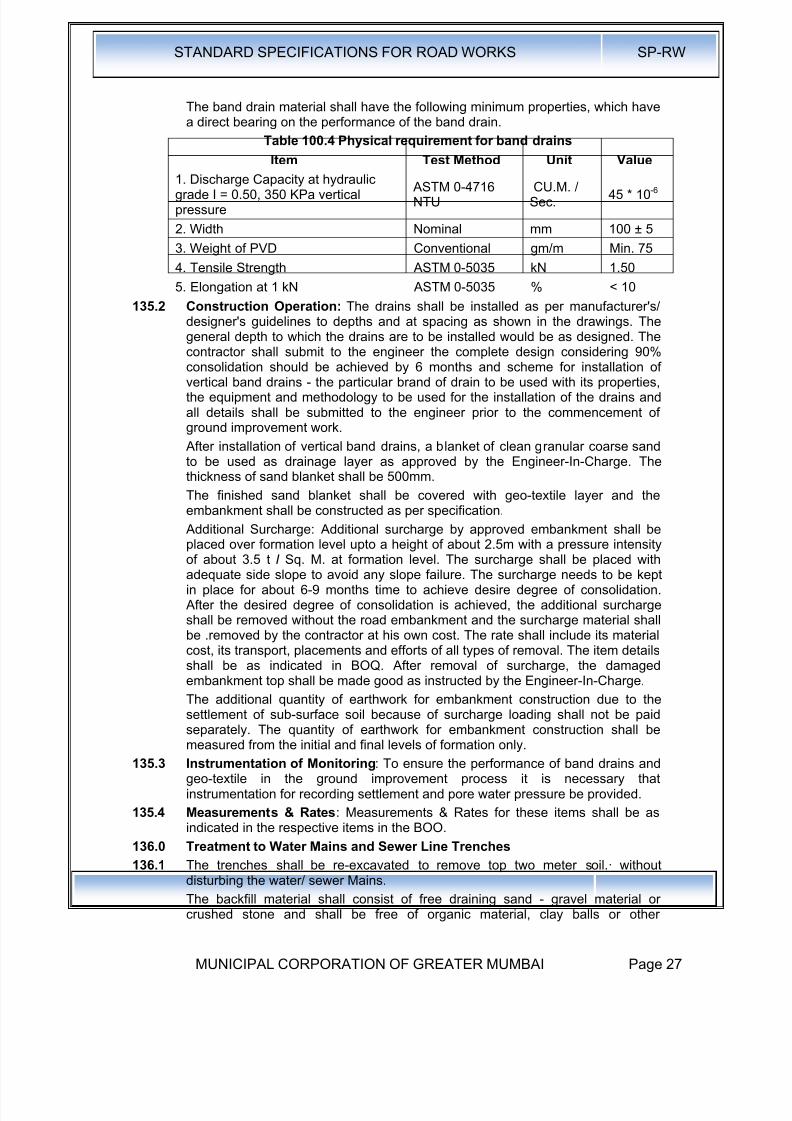
8/19/2019 MCGM Road Spec Volume -II
http://slidepdf.com/reader/full/mcgm-road-spec-volume-ii 31/176

8/19/2019 MCGM Road Spec Volume -II
http://slidepdf.com/reader/full/mcgm-road-spec-volume-ii 32/176
STANDARD SPECIFICATIONS FOR ROAD WORKS SP-RW
MUNICIPAL CORPORATION OF GREATER MUMBAI Page 28
deleterious matter of grading specified in the contract. The trench to be coveredwith Geo-membrane that shall be as per Clause 260.
136.2 Measurements for Payment:
Measurements for re-excavation of trenches and backfilling shall be per running
meter length of trench including disposal of excavated material. Themeasurements for Geo- membrane shall be per square meter of the membraneas laid as per the drawing.
136.3 Rates:
The contract unit rates shall be payment in full for all items such as excavation,dressing the -sides, backfilling the trench with granular material as perspecification including full compensation for all materials, labour tools equipmentand other incidentals to complete the work as shown on the drawing with allleads and lifts. The rate for geo-membrane shall be per square meter as perclause 260.
140.0 Excavation for Structures
141.0 Scope : Excavation for structures shall consist of the removal of material for theconstruction of foundations for bridges, culverts, retaining walls, headwalls, cut-off walls, pipe culverts and other similar structures, in accordance with therequirements of these Specifications and the lines and dimensions shown on thedrawings or as indicated by the Engineer. The work shall include construction ofthe necessary cofferdams and cribs and their subsequent removal; all necessarysheeting, shoring, bracing, draining and pumping; the removal of all logs,stumps, grubs and other deleterious matter and obstructions, necessary forplacing the foundations; trimming bottoms of excavations, backfilling and clearingup the site and the disposal of all surplus material.
141.1 Classification of Excavation : All materials involved in excavation shall beclassified in accordance with Clauses 102 and 103.
141.2 Construction Operations:
141.2.1 Setting Out: After the site has been cleared, the limits of excavation shall be setout true to lines, curves and slopes.
141.2.2 Excavation: Excavation shall be taken to the width of the lowest step of thefooting and the sides shall be left plumb where the nature of soil allows it. Wherethe nature of soil or the depth of the trench and season of the year do not permitvertical sides, the Contractor at his own expense shall put up necessary shoring,strutting and planking or cut slopes to a safer angle or both with due regard tothe safety of personnel and works and to the satisfaction of the Engineer.
The depth to which the excavation is to be carried out shall be as shown on the
drawings, unless the type of material encountered is such as to require changes,in which case the depth shall be as ordered by the Engineer. Propping shall beundertaken when any foundation or stressed zone from an adjoining structure iswithin a line of 1 vertical to 2 horizontal from the bottom of the excavation.
Where blasting is to be resorted to, the same shall be carried out in accordancewith Clause 103.3.2 and all precautions indicated therein observed. Whereblasting is likely to endanger adjoining foundations or other structures, necessaryprecautions such as controlled blasting, providing rubber mat cover to preventflying of debris etc. shall be taken to prevent any damage.
141.2.3 Dewatering and Protection: Normally, open foundations shall be laid dry.Where water is met with in excavation due to stream flow, seepage, springs, rainor other reasons, the Contractor shall take adequate measures such as bailing,pumping, constructing diversion channels, drainage channels, bunds, depressionof water level by well-point system, cofferdams, and other necessary works to

8/19/2019 MCGM Road Spec Volume -II
http://slidepdf.com/reader/full/mcgm-road-spec-volume-ii 33/176
STANDARD SPECIFICATIONS FOR ROAD WORKS SP-RW
MUNICIPAL CORPORATION OF GREATER MUMBAI Page 29
keep the foundation trenches dry when so required and to protect the greenconcrete / masonry against damage by erosion or sudden rising of water level.The methods to be adopted in this regard and other details thereof shall be left tothe choice of the Contractor but subject to approval of the Engineer. Approval ofthe Engineer shall, however, not relieve the Contractor of the responsibility forthe adequacy of dewatering and protection arrangements and for the quality andsafety of the works.
Where cofferdams are required, these shall be carried to adequate depths andheights, be safely designed and constructed and be made as watertight as isnecessary for facilitating construction to be carried out inside them. The interiordimensions of the cofferdams shall be such as to give sufficient clearance for theconstruction and inspection and to permit installation of pumping equipments,etc., inside the enclosed area.
If it is determined beforehand that the foundations cannot be laid dry or thesituation is found that the percolation is too heavy for keeping the foundation dry,the foundation concrete shall be laid under water by tremie pipe only. In case of
flowing water or artesian springs, the flow shall be stopped or reduced as far aspossible at the time of placing the concrete.
Pumping from the interior of any foundation enclosure shall be done in such amanner as to preclude the possibility of the movement of water through any freshconcrete. No pumping shall be permitted during the placing of concrete or for anyperiod of at least 24 hours thereafter, unless it is done from a suitable sumpseparated from the concrete work by a watertight wall or other similar means.
At the discretion of the Contractor, cement grouting or other approved methodsmay be used to prevent or reduce seepage and to protect the excavation area.
The Contractor shall take all precautions in diverting channels and in dischargingthe drained water as not to cause damage to the works, crops or any other
property.141.2.4 Preparation of Foundation: The bottom of the foundation shall be levelled both
longitudinally and transversely or stepped as directed by the Engineer. Beforefooting is laid, the surface shall be slightly watered and rammed. In the event ofexcavation having been made deeper than that shown on the drawings or asotherwise ordered by the Engineer, the extra depth shall be made up withconcrete or masonry of the foundation at the cost the Contractor.. Ordinary fillingshall not be used for the purpose to bring the foundation to level.
When rock or other hard strata is encountered, it shall be freed of all soft andloose material, cleaned and cut to a firm surface either level and stepped asdirected by the Engineer. All seams shall be cleaned our and filled with cement
mortar or grout to the satisfaction of the Engineer. In the case of excavation inrock, annular space around footing shall be filled with lean concrete (1:3:6nominal mix) up to the top level of rock.
If the depth of fill required is more than 1.5m above the top of the footing, fillingup to 1.5m above top of footing shall be done with lean concrete (1:3:6 nominalmix) followed by boulders grouted with cement.
When foundation piles are used, the excavation of each pit shall be substantiallycompleted before beginning pile-driving operations therein. After pile drivingoperations in a given pit are completed, all loose and displaced material thereinshall be removed to the elevation of the bottom of the footings.
141.2.5 Slips and Slip-outs: If there are any slips or slip-outs in the excavation, these
shall be removed by the Contractor at his own cost.

8/19/2019 MCGM Road Spec Volume -II
http://slidepdf.com/reader/full/mcgm-road-spec-volume-ii 34/176
STANDARD SPECIFICATIONS FOR ROAD WORKS SP-RW
MUNICIPAL CORPORATION OF GREATER MUMBAI Page 30
141.2.6 Public Safety: Near towns, villages and all frequented places, trenches andfoundation pits shall be securely fenced, provided with proper caution signs andmarked with red lights at night to avoid accidents. The Contractor shall takeadequate protective measures to see that the excavation operations do not affector damage adjoining structures. For safety precautions, guidance may be takenfrom 18:3764.
141.2.7 Backfilling : Backfilling shall be done with approved material after concrete ormasonry is fully set and carried out in such a way as not to cause undue thruston any part of the structure. All space between foundation masonry or concreteand the sides of excavation shall be refilled to the original surface in layers notexceeding 150 mm compacted thicknesses. The compaction shall be done withthe help of suitable equipment such as mechanical tamper, rammer, platevibrator etc., after necessary watering, so as to achieve a density not less thanthe field density before excavation.
141.2.8 Disposal of Surplus Excavated Materials: Clause 105 shall apply.
141.3 Measurements for Payment: Excavation for structures shall be measured in
cum. for each class of material encountered, limited to the dimensions shown onthe drawings or as directed by the Engineer. Excavation over increase width,cutting of slopes, shoring, shuttering and planking shall be deemed asconvenience for the Contractor in executing the work and shall not be measuredand paid for separately.
Preparation of rock foundation shall be measured in square metres. Foundationsealing, dewatering, including pumping shall be deemed to be incidental to thework unless separate provision is made for in the Contract. In the latter case,payment shall be on lump sum basis as provided in the Bill of Quantities.
141.4 Rates:
141.4.1 The Contract unit rate for the items of excavation for structures shall be payment
in full for carrying out the required operations including full compensation for:
o setting out;o construction of necessary cofferdams, cribs, sheeting, shoring, bracing and
their subsequent removal;o removal of all logs, stumps, grubs and other deleterious matter and
obstructions, for placing the foundations including trimming of bottoms ofexcavations;
o foundation sealing, dewatering including pumping when no separateprovision for it is made in the Contract;
o backfilling, clearing up the site and disposal of all surplus material within alllifts and leads up to 1000 m or as otherwise specified; and
o all labour, materials, tools, equipment, safety measures, diversion of trafficand incidentals necessary to complete the work to Specification.
141.4.2 The Contract unit rate for preparation of rock foundation shall be fullcompensation for cutting, trimming and cleaning the foundation surface and fillingI sealing of all seams with cement grout or mortar including all materials, labourand incidentals required for completing the work.
141.4.3 The Contract unit rate for transporting ·material from the excavation for structuresshall be full compensation for all labour, equipment, tools and incidentalsnecessary on account of the additional haul or transportation involved beyondthe initial lead of 1000m.
8/19/2019 MCGM Road Spec Volume -II
http://slidepdf.com/reader/full/mcgm-road-spec-volume-ii 35/176
STANDARD SPECIFICATIONS FOR ROAD WORKS SP-RW
MUNICIPAL CORPORATION OF GREATER MUMBAI Page 31
150.0 Embankment & Sub-Grade Construction
151.0 Embankment Construction:
151.1 General
151.1.1 Description: These Specifications shall apply to the construction of embankments
including sub-grades, earthen shoulders and miscellaneous backfills withapproved material obtained from roadway and drain excavation, borrow pits orother sources. All embankments, sub-grades, earthen shoulders andmiscellaneous backfills shall be constructed in accordance with the requirementsof these Specifications and in conformity with the lines, grades and crosssectionsshown on the drawings or as directed by the Engineer.
151.2 Materials and General Requirements:
151.2.1 Physical Requirements:
151.2.2 The materials used in embankments, sub-grades, earthen shoulders andmiscellaneous backfills shall be soil, moorum, gravel, a mixture of these or anyother material approved by the Engineer. Such materials shall be free of logs,
stumps, roots, rubbish or any other ingredient likely to deteriorate or affect thestability of the embankment / subgrade.
151.2.2.1 The following types of material shall be considered unsuitable for embankment:
a) Materials from swamps, marshes and bogs;
b) Peat, log, stump and perishable material; any soil that classifies as OL, OI, OHor Pt in accordance with IS:1498;
c) Materials susceptible to spontaneous combustion;
d) Materials in a frozen condition;
e) Clay having liquid limit exceeding 50 and plasticity index exceeding 35;
f) Materials with salts resulting in leaching in the embankment.
151.2.2.2 Expansive clay exhibiting marked swell and shrinkage properties ("free swellingindex" exceeding 50 per cent when tested as per IS: 2720 - Part-40) shall not beused as a fill material. Where expansive clay with acceptable "free swellingindex" value is used as a fill material, subgrade and top 500mm portion of theembankment just below sub-grade shall be non-expansive in nature.
151.2.2.3 Any fill material with a soluble sulphate content exceeding 1.9 grams ofsulphate (expressed as S03) per litre when tested in accordance with BS:1377Test 10, but using a 2:1 water-soil ratio shall not be deposited within 500 mm orother distance described in the Contract, of concrete, cement bound materials orother cementitious materials forming part of the Permanent Works.
Materials with a total sulphate content (expressed as S03) exceeding 0.5 per cent
by mass, when tested in accordance with 8S:1377 Test 9 shall not be depositedwithin 500mm, or other distances described in the Contract, of metallic itemsforming part of the Permanent Works.
151.2.2.4 The size of the coarse material in the mixture of earth shall ordinarily notexceed 75mm when being placed in the embankment and 50mm when placed inthe sub-grade. However, the Engineer may at his discretion permit the use ofmaterial coarser than this also if he is satisfied that the same will not present anydifficulty as regards the placement of fill material and its compaction to therequirements of these Specifications. The maximum particle size shall not bemore than two-thirds of the compacted layer thickness.
151.2.2.5 Ordinarily, only the materials satisfying the density requirements given in Table
100.5 shall be employed for the construction of the embankment and the sub-grade.
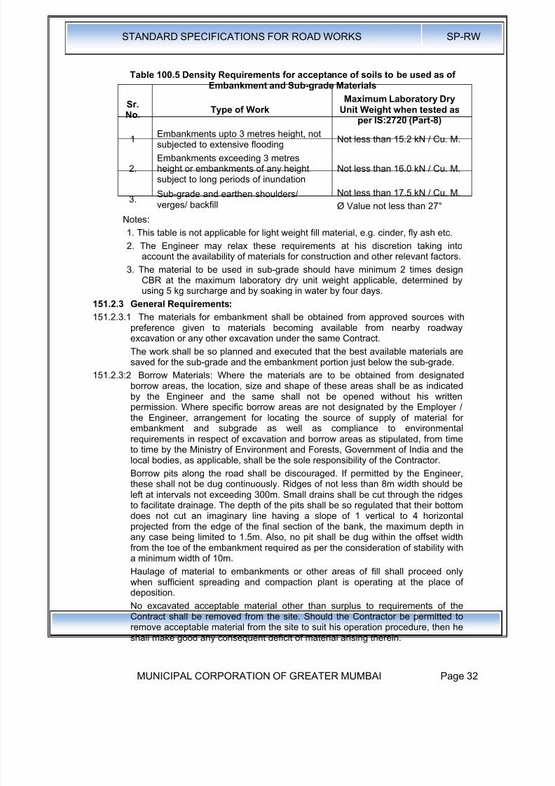
8/19/2019 MCGM Road Spec Volume -II
http://slidepdf.com/reader/full/mcgm-road-spec-volume-ii 36/176
STANDARD SPECIFICATIONS FOR ROAD WORKS SP-RW
MUNICIPAL CORPORATION OF GREATER MUMBAI Page 32
Table 100.5 Density Requirements for acceptance of soils to be used as ofEmbankment and Sub-grade Materials
Sr.No.
Type of WorkMaximum Laboratory Dry
Unit Weight when tested as
per IS:2720 (Part-8)1
Embankments upto 3 metres height, notsubjected to extensive flooding
Not less than 15.2 kN / Cu. M.
2.Embankments exceeding 3 metresheight or embankments of any heightsubject to long periods of inundation
Not less than 16.0 kN / Cu. M.
3.Sub-grade and earthen shoulders/verges/ backfill
Not less than 17.5 kN / Cu. M.
Ø Value not less than 27°
Notes:
1. This table is not applicable for light weight fill material, e.g. cinder, fly ash etc.
2. The Engineer may relax these requirements at his discretion taking intoaccount the availability of materials for construction and other relevant factors.
3. The material to be used in sub-grade should have minimum 2 times designCBR at the maximum laboratory dry unit weight applicable, determined byusing 5 kg surcharge and by soaking in water by four days.
151.2.3 General Requirements:
151.2.3.1 The materials for embankment shall be obtained from approved sources withpreference given to materials becoming available from nearby roadwayexcavation or any other excavation under the same Contract.
The work shall be so planned and executed that the best available materials aresaved for the sub-grade and the embankment portion just below the sub-grade.
151.2.3:2 Borrow Materials: Where the materials are to be obtained from designatedborrow areas, the location, size and shape of these areas shall be as indicatedby the Engineer and the same shall not be opened without his writtenpermission. Where specific borrow areas are not designated by the Employer /the Engineer, arrangement for locating the source of supply of material forembankment and subgrade as well as compliance to environmentalrequirements in respect of excavation and borrow areas as stipulated, from timeto time by the Ministry of Environment and Forests, Government of India and thelocal bodies, as applicable, shall be the sole responsibility of the Contractor.
Borrow pits along the road shall be discouraged. If permitted by the Engineer,these shall not be dug continuously. Ridges of not less than 8m width should be
left at intervals not exceeding 300m. Small drains shall be cut through the ridgesto facilitate drainage. The depth of the pits shall be so regulated that their bottomdoes not cut an imaginary line having a slope of 1 vertical to 4 horizontalprojected from the edge of the final section of the bank, the maximum depth inany case being limited to 1.5m. Also, no pit shall be dug within the offset widthfrom the toe of the embankment required as per the consideration of stability witha minimum width of 10m.
Haulage of material to embankments or other areas of fill shall proceed onlywhen sufficient spreading and compaction plant is operating at the place ofdeposition.
No excavated acceptable material other than surplus to requirements of theContract shall be removed from the site. Should the Contractor be permitted toremove acceptable material from the site to suit his operation procedure, then heshall make good any consequent deficit of material arising therein.
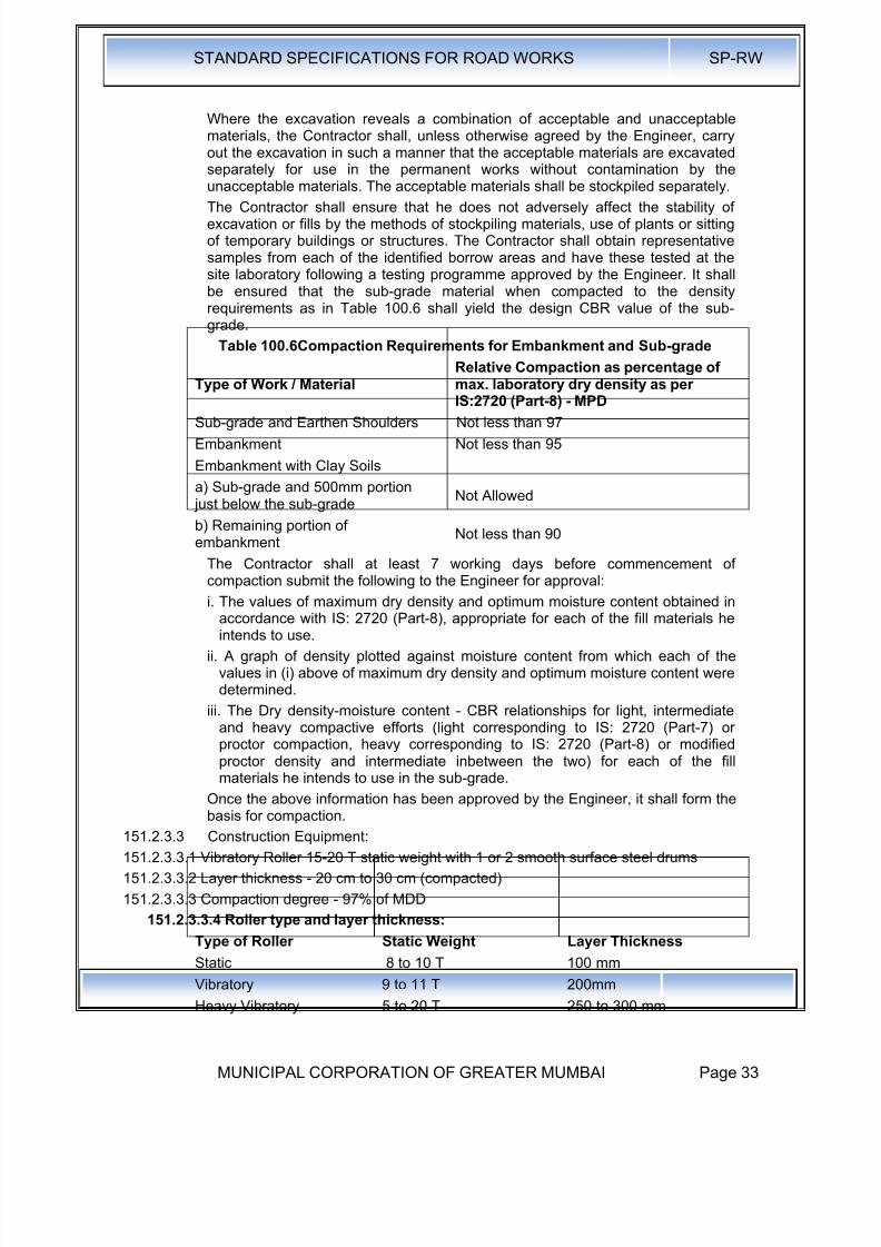
8/19/2019 MCGM Road Spec Volume -II
http://slidepdf.com/reader/full/mcgm-road-spec-volume-ii 37/176
STANDARD SPECIFICATIONS FOR ROAD WORKS SP-RW
MUNICIPAL CORPORATION OF GREATER MUMBAI Page 33
Where the excavation reveals a combination of acceptable and unacceptablematerials, the Contractor shall, unless otherwise agreed by the Engineer, carryout the excavation in such a manner that the acceptable materials are excavatedseparately for use in the permanent works without contamination by theunacceptable materials. The acceptable materials shall be stockpiled separately.
The Contractor shall ensure that he does not adversely affect the stability ofexcavation or fills by the methods of stockpiling materials, use of plants or sittingof temporary buildings or structures. The Contractor shall obtain representativesamples from each of the identified borrow areas and have these tested at thesite laboratory following a testing programme approved by the Engineer. It shallbe ensured that the sub-grade material when compacted to the densityrequirements as in Table 100.6 shall yield the design CBR value of the sub-grade.
Table 100.6Compaction Requirements for Embankment and Sub-grade
Type of Work / MaterialRelative Compaction as percentage ofmax. laboratory dry density as perIS:2720 (Part-8) - MPD
Sub-grade and Earthen Shoulders Not less than 97
Embankment Not less than 95
Embankment with Clay Soils
a) Sub-grade and 500mm portion just below the sub-grade
Not Allowed
b) Remaining portion ofembankment
Not less than 90
The Contractor shall at least 7 working days before commencement ofcompaction submit the following to the Engineer for approval:
i. The values of maximum dry density and optimum moisture content obtained inaccordance with IS: 2720 (Part-8), appropriate for each of the fill materials heintends to use.
ii. A graph of density plotted against moisture content from which each of thevalues in (i) above of maximum dry density and optimum moisture content weredetermined.
iii. The Dry density-moisture content - CBR relationships for light, intermediateand heavy compactive efforts (light corresponding to IS: 2720 (Part-7) orproctor compaction, heavy corresponding to IS: 2720 (Part-8) or modifiedproctor density and intermediate inbetween the two) for each of the fillmaterials he intends to use in the sub-grade.
Once the above information has been approved by the Engineer, it shall form thebasis for compaction.
151.2.3.3 Construction Equipment:
151.2.3.3.1 Vibratory Roller 15-20 T static weight with 1 or 2 smooth surface steel drums
151.2.3.3.2 Layer thickness - 20 cm to 30 cm (compacted)
151.2.3.3.3 Compaction degree - 97% of MDD
151.2.3.3.4 Roller type and layer thickness:
Type of Roller Static Weight Layer Thickness
Static 8 to 10 T 100 mm
Vibratory 9 to 11 T 200mmHeavy Vibratory 5 to 20 T 250 to 300 mm
8/19/2019 MCGM Road Spec Volume -II
http://slidepdf.com/reader/full/mcgm-road-spec-volume-ii 38/176
STANDARD SPECIFICATIONS FOR ROAD WORKS SP-RW
MUNICIPAL CORPORATION OF GREATER MUMBAI Page 34
151.2.4 Construction Operations: These specifications shall "apply to the constructionof embankments, shoulders and miscellaneous backfills with approved materialobtained either from excavation for road construction or brought from outside by
the contractor. All embankments shall be constructed in accordance with therequirements of these specifications and in conformity with the lines, grades andcross sections shown on the drawings or as directed by the Engineer.
151.2.5 After the site has been cleared, the work shall be set out to Clause 54. The limitsof the embankment shall be marked by fixing better pegs on both sides at regularintervals as guides before commencing the earthwork. To ensure their safety, itis desirable to fix the pegs about 0.5 metres back from the actual limits of the filland to paint them in distinctive colour.
In all cases, the original ground shall be compacted by rolling as directed by theEngineer. When the height of the embankment is less than 0.5m and the originalground does not already have a relative compaction of at least 95% then sameshall be loosened to a depth of 0.5m watered and compacted in layers not
exceeding 250mm in loose thickness to the maximum dry density of the material,determined in accordance with IS: 2720 (Part-VII). However, before relaying andcompacting the loosened material, the surface below this level shall be suitablycompacted as directed by the Engineer. When so directed by the Engineer, anysuitable materials occurring in the embankment foundation shall be removed andreplaced by approved material suitably compacted. Embankment work shall notproceed until the foundations for embankment have been inspected by theEngineer, found satisfactory and approved.
151.2.6 Spreading Materials in layers and bringing to appropriate Moisture Content: Theembankment material shall be spread uniformly over the entire width of theembankment in layers not exceeding 250mm in loose thickness. Successive
layers of embankment shall not be placed until the layer under construction hasbeen thoroughly compacted to the requirements set down herein under:
Moisture content of the material shall be checked at the source of supply and iffound less than specified for compaction, the same shall be made good either atthe source or after spreading the soil in loose thickness for compaction. In lattercase, water shall be sprinkled directly from hose line or from a water tankmounted on a truck, flooding shall not be permitted under any circumstances.
If the material delivered to the road bed is too wet, it shall be dried, bycompaction. Should circumstances arise where owing to wet weather, themoisture content cannot be reduced to the required amount by the aboveprocedure, work on compaction shall be suspended.
Moisture content of each layer of soil shall be adjusted (making due allowancefor evaporation loss), so that at the time of compaction, it is in the range of 1 %above 2% below the optimum moisture content.
After adding the required amount of water, soil shall be processed by means ofhammer rotary mixer or as otherwise until the layer is uniformly wet.
Clods or hard lumps of earth shall be broken to have maximum size of 150mm,when being placed in the lower layers of the embankment and maximum size of60mm, when being placed in the top 0.5 meter portion of the embankment belowthe sub-grade.
151.2.7 Compaction: Each layer of the material shall be thoroughly compacted by usinga power roller of not less than 8-10 Tonne or any other approved plant. Rolling
shall be done as specified in Clause 151.2.7. The field dry density of material
8/19/2019 MCGM Road Spec Volume -II
http://slidepdf.com/reader/full/mcgm-road-spec-volume-ii 39/176
STANDARD SPECIFICATIONS FOR ROAD WORKS SP-RW
MUNICIPAL CORPORATION OF GREATER MUMBAI Page 35
after compaction shall be not less than specified % in Table 100.6 of themaximum laboratory dry density as per IS:2720 (Part-VIII).
Subsequent layers shall be placed only after the finished layer has been testedaccording to Clause 622 and accepted by the Engineer.
When density measurements reveal any soft areas in the embankment, furthercompaction shall be carried out as directed by the Engineer. If in spite of that thespecified compaction is not achieved, the material in the soft areas shall beremoved and replaced by approved material, compacted to the densityrequirements and satisfaction of the Engineer.
The surface of the embankment at all time during construction be maintained atsuch cross fall as well shed water and to prevent flooding.
151.2.8 Rolling : A power roller shall, as a rule, be not less than 10 tonnes but if at anytime still heavier rollers are required on the works, the contractors shall have tobring them as may be directed by the Engineer. In case of trenches not morethan 2.5 m in width, an earth master or any other similar equipment manually ormachine operated, shall be invariably employed.
Rolling shall progress from edges to the centre of the road in strips parallel to thecentre line of the road. Rolling shall be done by lapping uniformly eachproceeding rear wheel track by at least one half width of the track. On superelevations, rolling shall be started at inner edge and shall progress towards outeredge. During and after rolling, the surface shall be checked for grade andcamber. Rolling shall be started worked or stopped without jerks. Rolling shallnot be normally done in length less than 100m (300'). On completion of day'swork, the roller shall be made to stand on the side width of the road and shall beguarded by a watchman.
A red lantern shall be hung on the roller at night so as to be visible from . bothsides of the road.
151.2.9 Finishing Operations: These shall include the work of shaping and dressing theshoulders, road bed and side slopes to conform to the alignment, levels, crosssections and dimensions shown on the drawings or as directed by the Engineer,subject to the surface tolerances described in Clause 613. Both the upper andlower ends of the side slopes shall be rounded off to improve appearance andmerge the embankment with the adjacent terrain.
When earthwork operations have been subsequently, compacted the roadwayarea shall be cleared or all debris and ugly scars in the construction areas,responsible for objectionable appearance be eliminated.
152.0 Construction of Embankment and Sub-grade under Special Conditions:
152.1 Embankment and Sub-grade around Structures: To avoid interference withthe construction of abutments, wing walls or of culvert / bridge structures, theContractor shall, at points to be determined by the Engineer suspend work onembankment forming approaches to such structures, until such time as theconstruction of the latter is sufficiently advanced to permit the completion ofapproaches without the risk of damage to the structure.
Unless directed otherwise, the filling around culverts, bridges and otherstructures upto a distance of twice the height of the road from the back of theabutment shall be carried out independent of the work on the main embankment.The fill material shall not be placed against any abutment or wing wall, unlesspermission has been given by the Engineer but in any case not until the concreteor masonry has been in position for 14 days. The embankment and subgrade
shall be brought up simultaneously in equal layers on each side of the structure
8/19/2019 MCGM Road Spec Volume -II
http://slidepdf.com/reader/full/mcgm-road-spec-volume-ii 40/176
STANDARD SPECIFICATIONS FOR ROAD WORKS SP-RW
MUNICIPAL CORPORATION OF GREATER MUMBAI Page 36
to avoid displacement and unequal pressure. The sequence of work in thisregard shall be got approved from the Engineer.
The material used for backfill shall not be an organic soil or highly plastic clayhaving plasticity index and liquid limit more than 20 and 40 respectively when
tested according to IS:2720 (Part-5). Filling behind abutments and wing walls forall structures shall conform to the general guidelines given in Appendix 6 ofIRC:78 (Standard Specifications and Code of Practice for Road Bridges - SectionVII) in respect of the type of material, the extent of backfill, its laying andcompaction etc. The fill material shall be deposited in horizontal layers in loosethickness and compacted thoroughly to the requirements of Table 100.6.
Where the provision of any filter medium is specified behind the abutment, thesame shall be laid in layers simultaneously with the laying of fill material. Thematerial used for filter shall conform to the requirements for filter medium speltout in Clause 120.2.2 unless otherwise specified in the Contract.
Where it may be impracticable to use conventional rollers, the compaction shallbe carried out by appropriate mechanical means such as small vibratory roller,
plate compactor or power rammer. Care shall be taken to see that thecompaction equipment does not hit or come too close to any structural memberso as to cause any damage to them or excessive pressure against the structure.
152.2 Construction of embankment over ground incapable of supportingconstruction equipment: Where embankment is to be constructed acrossground which will not support the weight of repeated heavy loads of constructionequipment, the first layer of the fill may be constructed by placing successiveloads of material in a uniformly distributed layer of a minimum thickness requiredto support the construction equipment so that no pore pressure is built up or nobearing pressure failure of sub-soil takes place to cause movement of sub-soil aspermitted by the Engineer. The Contractor, if so desired by him, may also use
suitable geosynthetic material to increase the bearing capacity of the foundation.This exception to normal procedure will not be permitted where, in the opinion ofthe Engineer, the embankments could be constructed in the approved mannerover such ground by the use of lighter or modified equipment after properditching and drainage have been provided. Where this exception is permitted, theselection of the material and the construction procedure to obtain an acceptablelayer shall be the responsibility of the Contractor. The cost of providing suitabletraffic conditions for construction equipment over any area of the Contract will bethe responsibility of the Contractor and no extra payment will be made to him.The remainder of the embankment shall be constructed as specified in Clause151.2.4.
152.3 Embankment Construction under water : Where filling or backfilling is to be
placed under water, only acceptable granular material or rock shall be usedunless otherwise approved by the Engineer. Acceptable granular material shallconsist of graded, hard durable particles with maximum particle size notexceeding 75mm. The material should be non-plastic having uniformly coefficientof not less than 10. The material placed I open water shall be deposited by endtipping without compaction.
152.4 Earthwork for High Embankment: In the case of high embankments, theContractor shall normally use the material from the specified borrow area. Incase, he desires to use different material for his own convenience, he shall haveto carry out necessary soil investigations and redesign the high embankment athis own cost. The Contractor shall then furnish the soil test data and design of
high embankment for approval of the Engineer, who reserves the right to acceptor reject it.
8/19/2019 MCGM Road Spec Volume -II
http://slidepdf.com/reader/full/mcgm-road-spec-volume-ii 41/176
STANDARD SPECIFICATIONS FOR ROAD WORKS SP-RW
MUNICIPAL CORPORATION OF GREATER MUMBAI Page 37
If necessary, stage construction of fills and any controlled rates of filling shall becarried out in accordance with the Contract including installation of instrumentsand its monitoring.
Where required, the Contractor shall surcharge embankments or other areas of
fill with approved material for the periods specified in the Contract. If settlementof surcharged fill results in any surcharging material, which is unacceptable foruse in the fill being surcharged, lying below formation level, the Contractor shallremove the unacceptable material and dispose it as per direction of theEngineer. He shall then bring the resultant level up to formation level withacceptable material.
152.4.1 Earthwork for widening existing road embankment : When an existingembankment and/or subgrade is to be widened and its slopes are steeper than 1vertical on 4 horizontal, continuous horizontal benches, each at least 300mmwide, shall be cut into the old slope for ensuring adequate bond with the freshembankment / subgrade material to be added. The material obtained from cuttingbenches could be utilized in the widening of the embankment subgrade.
However, when the existing slope against which the fresh material is to beplaced is flatter than 1 vertical on 4 horizontal, the slope surface may only beploughed or scarified instead of resorting to benching.
Where the width of the widened portions is insufficient to permit the use ofconventional rollers, compaction shall be carried out with the help of smallvibratory rollers / plate compactors / power rammers or any other appropriateequipment approved by the Engineer. End dumping of material from trucks forwidening operations shall be avoided except in difficult circumstances when theextra width is too narrow to permit the movement of any other types of haulingequipment.
152.4.2 Earthwork for embankment and subgrade to be placed against sloping
ground Where an embankment / subgrade is to be placed against slopingground, the latter shall be appropriately benched or ploughed / scarified asrequired in Clause 152.1 before placing the embankment / subgrade material.Extra earthwork involved in benching or due to ploughing / scarifying etc. shall beconsidered incidental to the work.
For wet conditions, benches with slightly inward fall and subsoil drains at thelowest point shall be provided as per the drawings, before the fill is placedagainst sloping ground. Where the Contract requires construction of transversesubsurface drain at the cut-fill interface, work on the same shall be carried out toClause 309 in proper sequence with the embankment and subgrade work asapproved by the Engineer.
152.4.3 Earthwork over existing road surface: Where the embankment is to be placedover an existing road surface, the work shall be carried out as indicated below:
a) If the existing road surface is of granular or bituminous type and lies within 1 mof the new sub-grade level, the same shall be scarified to a depth of 150mm ormore is specified, so as to provide ample bond between the old and newmaterial ensuring that at least 500mm portion below the top of new sub-gradelevel is compacted to the desired density.
b) If the existing road surface is of cement concrete type and lies within 1 m ofthe new sub-grade level the same shall be removed completely.
c) If the level difference between the existing surface and the new formation levelis more than 1 m, the existing surface shall be permitted to stay in placewithout any modification.
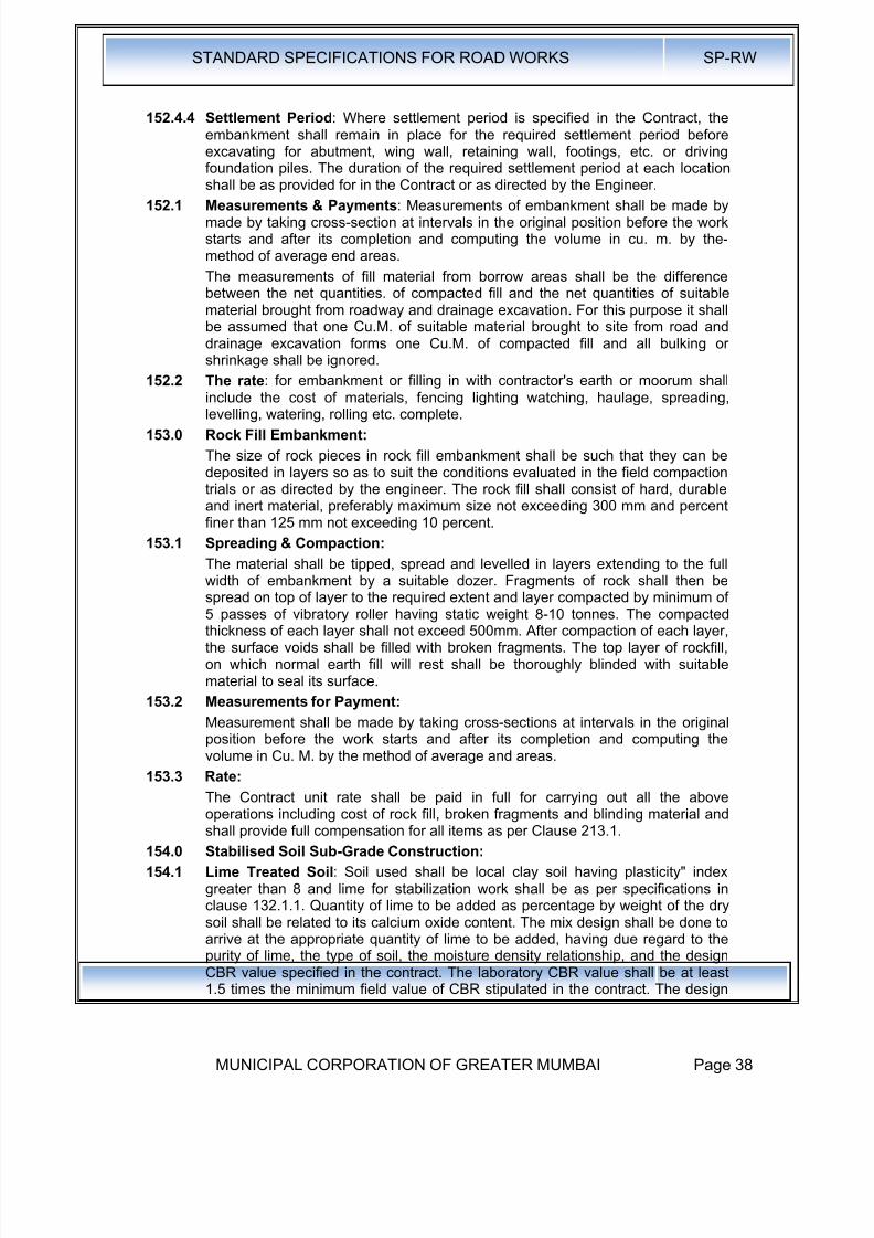
8/19/2019 MCGM Road Spec Volume -II
http://slidepdf.com/reader/full/mcgm-road-spec-volume-ii 42/176
STANDARD SPECIFICATIONS FOR ROAD WORKS SP-RW
MUNICIPAL CORPORATION OF GREATER MUMBAI Page 38
152.4.4 Settlement Period: Where settlement period is specified in the Contract, theembankment shall remain in place for the required settlement period beforeexcavating for abutment, wing wall, retaining wall, footings, etc. or drivingfoundation piles. The duration of the required settlement period at each locationshall be as provided for in the Contract or as directed by the Engineer.
152.1 Measurements & Payments: Measurements of embankment shall be made bymade by taking cross-section at intervals in the original position before the workstarts and after its completion and computing the volume in cu. m. by the-method of average end areas.
The measurements of fill material from borrow areas shall be the differencebetween the net quantities. of compacted fill and the net quantities of suitablematerial brought from roadway and drainage excavation. For this purpose it shallbe assumed that one Cu.M. of suitable material brought to site from road anddrainage excavation forms one Cu.M. of compacted fill and all bulking orshrinkage shall be ignored.
152.2 The rate: for embankment or filling in with contractor's earth or moorum shall
include the cost of materials, fencing lighting watching, haulage, spreading,levelling, watering, rolling etc. complete.
153.0 Rock Fill Embankment:
The size of rock pieces in rock fill embankment shall be such that they can bedeposited in layers so as to suit the conditions evaluated in the field compactiontrials or as directed by the engineer. The rock fill shall consist of hard, durableand inert material, preferably maximum size not exceeding 300 mm and percentfiner than 125 mm not exceeding 10 percent.
153.1 Spreading & Compaction:
The material shall be tipped, spread and levelled in layers extending to the fullwidth of embankment by a suitable dozer. Fragments of rock shall then bespread on top of layer to the required extent and layer compacted by minimum of5 passes of vibratory roller having static weight 8-10 tonnes. The compactedthickness of each layer shall not exceed 500mm. After compaction of each layer,the surface voids shall be filled with broken fragments. The top layer of rockfill,on which normal earth fill will rest shall be thoroughly blinded with suitablematerial to seal its surface.
153.2 Measurements for Payment:
Measurement shall be made by taking cross-sections at intervals in the originalposition before the work starts and after its completion and computing thevolume in Cu. M. by the method of average and areas.
153.3 Rate:
The Contract unit rate shall be paid in full for carrying out all the aboveoperations including cost of rock fill, broken fragments and blinding material andshall provide full compensation for all items as per Clause 213.1.
154.0 Stabilised Soil Sub-Grade Construction:
154.1 Lime Treated Soil: Soil used shall be local clay soil having plasticity" indexgreater than 8 and lime for stabilization work shall be as per specifications inclause 132.1.1. Quantity of lime to be added as percentage by weight of the drysoil shall be related to its calcium oxide content. The mix design shall be done toarrive at the appropriate quantity of lime to be added, having due regard to thepurity of lime, the type of soil, the moisture density relationship, and the designCBR value specified in the contract. The laboratory CBR value shall be at least1.5 times the minimum field value of CBR stipulated in the contract. The design
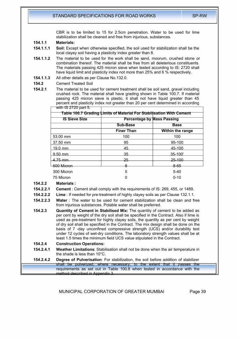
8/19/2019 MCGM Road Spec Volume -II
http://slidepdf.com/reader/full/mcgm-road-spec-volume-ii 43/176
STANDARD SPECIFICATIONS FOR ROAD WORKS SP-RW
MUNICIPAL CORPORATION OF GREATER MUMBAI Page 39
CBR is to be limited to 15 for 2.5cm penetration. Water to be used for limestabilization shall be cleaned and free from injurious, substances.
154.1.1 Materials:
154.1.1.1 Soil: Except when otherwise specified, the soil used for stabilization shall be the
local clayey soil having a plasticity index greater than 8.154.1.1.2 The material to be used for the work shall be sand, moorum, crushed stone or
combination thereof. The material shall be free from all deleterious constituents.The materials passing 425 micron sieve when tested according to IS: 2720 shallhave liquid limit and plasticity index not more than 25% and 6 % respectively.
154.1.1.3 All other details as per Clause No.132.0.
154.2 Cement Treated Soil
154.2.1 The material to be used for cement treatment shall be soil sand, gravel includingcrushed rock. The material shall have grading shown in Table 100.7. If materialpassing 425 micron sieve is plastic, it shall not have liquid greater than 45percent and plasticity index not greater than 20 per cent determined in according
with IS 2720 part 5.Table 100.7 Grading Limits of Material For Stabilisation With Cement
IS Sieve Size Percentage by Mass Passing
Sub-Base Base
Finer Than Within the range
53.00 mm 100 100
37.50 mm 95 95-100
19.0 mm 45 45-100
9.50 mm 35 35-100'
4.75 mm 25 25-100600 Micron 8 8-65
300 Micron 5 5-40
75 Micron 0 0-10
154.2.2 Materials :
154.2.2.1 Cement : Cement shall comply with the requirements of IS: 269, 455, or 1489.
154.2.2.2 Lime : If needed for pre-treatment of highly clayey soils as per Clause 132.1.1.
154.2.2.3 Water : The water to be used for cement stabilization shall be clean and freefrom injurious substances. Potable water shall be preferred.
154.2.3 Quantity of Cement in Stabilised Mix: The quantity of cement to be added as
per cent by weight of the dry soil shall be specified in the Contract. Also if lime isused as pre-treatment for highly clayey soils, the quantity as per cent by weightof dry soil shall be specified in the Contract. The mix design shall be done on thebasis of 7 -day unconfined compressive strength (UCS) and/or durability testunder 12 cycles of wet-dry conditions. The laboratory strength values shall be atleast 1.5 times the minimum field UCS value stipulated in the Contract.
154.2.4 Construction Operations:
154.2.4.1 Weather Limitations: Stabilisation shall not be done when the air temperature inthe shade is less than 10°C.
154.2.4.2 Degree of Pulverisation: For stabilization, the soil before addition of stabilizershall be pulverized, where necessary, to the extent that it passes the
requirements as set out in Table 100.8 when tested in accordance with themethod described in Appendix 3.

8/19/2019 MCGM Road Spec Volume -II
http://slidepdf.com/reader/full/mcgm-road-spec-volume-ii 44/176

8/19/2019 MCGM Road Spec Volume -II
http://slidepdf.com/reader/full/mcgm-road-spec-volume-ii 45/176
STANDARD SPECIFICATIONS FOR ROAD WORKS SP-RW
MUNICIPAL CORPORATION OF GREATER MUMBAI Page 41
No.151.2.6. Moisture control of both pond ash and cover shall be doneas per Clause No.151.2.6.
b). For better compaction of pond ash, it is preferred to have a vibratoryroller with frequency' range (1800-2200 rpm). For compaction of pond
ash static as well as vibratory rollers may be employed. In case ofvibratory roller, the lift thickness shall be restricted to 25cm compactedover the entire width of the embankment. The pond ash should becompacted to 95% of its MDD and in no case its maximum densityshould be less than 1.2 gm/cc. Moisture content of pond ash atcompaction will vary from OMC to OMC +2%.
c) After achieving the designed thickness of first pond ash layer, a coversoil layer of 40cm compacted thickness shall be provided as ClauseNO.151.
d) The same procedure shall be adopted for subsequent pond ash and soillayers, till the required height is achieved.
e) Pond ash shall be used upto 500mm below GSB layer.
f) Width of side cover soil shall be 2000mm measured horizontally. Thecover soil shall comprise soil as per Clause 151.
d. Payment shall be made in accordance with Clause 151.

8/19/2019 MCGM Road Spec Volume -II
http://slidepdf.com/reader/full/mcgm-road-spec-volume-ii 46/176
STANDARD SPECIFICATIONS FOR ROAD WORKS SP-RW
MUNICIPAL CORPORATION OF GREATER MUMBAI Page 42
200.0 Granular Sub-Base I Base
210.0 Granular Sub-Base:
211.0 Materials: The material to be used for the work shall be natural sand, gravel,
crushed stone, or combination thereof depending upon the grading required.Materials like crushed slag, crushed concrete may be allowed only with thespecific approval of the Engineer. The material ~hall be free from organic orother deleterious constituents and conform to one of the grading given in Table200.2 as specified in the contract.
211.1 Physical Requirement : The material shall have a 10 per cent fines value of 50KN or more (for sample in soaked condition) when tested in compliance withIS:812 (Part-III). The water absorption value of the coarse aggregate shall bedetermined as per IS:2386 (Part-III); if this value is greater than 2%, thesoundness test shall be carried out on the material as per IS:383.
211.2 Grading Requirement : The. grading· in Table 200.2 is in respect of coarse
graded granular sub-base materials, one each for maximum particle size of75mm, 53mm and 26.5mm. The coarser grading is intended to make the layer toact as drainage layer. Hence, if directed by the Engineer a separation layer byway of geo-textile as per Clause 260 between sub-grade and sub-base and layerof geo-grid in between sub-base and base be provided. The grading to beadopted for a project shall be as specified in the contract.
Table 200.2 Grading for Coarse Graded Granular Sub-Base Materials(Permeable Layer)
IS Sieve DesignationPer Cent by weight passing the IS Sieve
Grading I Grading II Grading III
75.0 mm 100 - -
53.0 mm 100 -
26.5 mm 55-75 50-80 100
9.50 mm
4.75 mm 10-30 15-35 25-45
2.36 mm
0.425 mm
0.075 mm <5 <5 <5
CBR Value (minimum) with 5 Kg.Surcharge at Maximum Dry
Density as per IS:2720 (Part-8)and after soaking for four days ,
30 25 20
Note:
1.The material passing 425 micron (0.425mm) sieve for all the three gradingswhen tested according to IS:2720 (Part-5) shall have liquid limit and plasticityindex not more than 25 and 6 per cent respectively.
2.The layer of coarse graded sub-base shall be separated from subgrade byproviding suitable geo-textile of strength mentioned in the contract and at topa layer of geo-grid or geo-net specified in contract· be provided.
3.The material passing 19 mm sieve and duly adjusted for fraction retained on19 mm sieve shall be used for finding maximum dry density.
211.3 Strength of Sub-Base : It shall be ensured prior to actual execution that thematerial to be used in the sub-base satisfies requirement of 1.1 times the design

8/19/2019 MCGM Road Spec Volume -II
http://slidepdf.com/reader/full/mcgm-road-spec-volume-ii 47/176
STANDARD SPECIFICATIONS FOR ROAD WORKS SP-RW
MUNICIPAL CORPORATION OF GREATER MUMBAI Page 43
CBR mentioned in Table 200.2 and other physical requirements whencompacted and finished.
When directed by the Engineer, this shall be verified by performing CBR test inthe laboratory as required on specimens re-moulded at maximum dry density
and at OMC using material passing 19 mm sieve.The value of laboratory CBR shall be 1.5 times the design CBR mentioned inTable 200.2.
211.4 Equipment : Roller 80 to 100 KN weight if thickness of layer is less than 100mm. 80 to 100 KN static weight vibratory or pneumatic tyred roller of 200 to 300KN weight having minimum tyre pressure of 0.7 KN /sq. m.
212.0 Preparation of Sub-grade: Immediately prior to ·the laying of subbase, the subgrade already finished to Clause 100 or 150 as applicable shall be prepared byremoving all vegetation and other extraneous matter, lightly sprinkled with waterif necessary and rolled with two passes of 80-100 kN smooth wheeled roller.
212.1 Spreading and Compacting: The sub-base material of grading specified in the
Contract shall be spread on the prepared sub-grade with the help of a motorgrader of adequate capacity, its blade having hydraulic controls suitable for initialadjustment and for maintaining the required slope and grade during the operationor other means as approved by the Engineer. When the sub-base materialconsists of combination of materials mentioned in Clause 211, mixing shall bedone mechanically by the mix-in-place method.
Manual mixing shall be permitted only where the width of laying is not adequatefor mechanical operations, as in small-sized jobs. The equipment used for mix-in-place construction shall be a rotavator or similar approved equipment capable ofmixing the material to the desired degree. If so desired by the Engineer, trail runswith the equipment shall be carried out to establish its suitability for the work.
Moisture content of the loose material shall be checked in accordance withIS:2720 (Part-2) and suitably adjusted by sprinkling additional water from a truckmounted or trailer mounted water and suitable for applying water uniformly andat controlled quantities to variable widths of surface or other means approved bythe Engineer so that, at the time of compaction, it is from 1 per cent above to 2per cent below the optimum moisture content corresponding to IS:2720 (Part-8).While adding water, due allowance shall be made for evaporation losses. Afterwater has been added, the material shall be processed by mechanical or otherapproved means like disc harrows, rotavators until the layer is uniformly wet.
Immediately thereafter, rolling shall start. If the thickness of the compacted layerdoes not exceed 100mm, a smooth wheeled roller of 80 to 100 kN weight may beused. For a compacted single layer upto 225mm, the compaction shall be done
with the help of a vibratory roller of minimum 80 to 100 kN static weight with plaindrum or pad foot-drum or heavy pneumatic tyred roller of minimum 200 to 300 kNweight having a minimum tyre pressure of 0.7 MN/m2 or equivalent capacity rollercapable of achieving the required compaction. Rolling shall commence at thelower edge and proceed towards the upper edge longitudinally for portionshaving unidirectional cross fall and super-elevation and shall commence at theedges and progress towards the centre for portions having cross fall on bothsides.
Each pass of the roller shall uniformly overlap not less than one-third of the trackmade in the preceding pass. During rolling, the grade and cross fall (camber)shall be checked and any high spots or depressions, which become apparent,corrected by removing or adding fresh material. The speed of the roller shall notexceed 5 km per hour.

8/19/2019 MCGM Road Spec Volume -II
http://slidepdf.com/reader/full/mcgm-road-spec-volume-ii 48/176
STANDARD SPECIFICATIONS FOR ROAD WORKS SP-RW
MUNICIPAL CORPORATION OF GREATER MUMBAI Page 44
Rolling shall be continued till the density achieved is at least 98 per cent of themaximum dry density for the material determined as per IS:2720 (Part-8). Thesurface of any layer of material on completion of compaction shall be well closed,free from movement under compaction equipment and from compaction planes,ridges, cracks or loose material. All loose, segregated or otherwise defectiveareas shall be made good to the full thickness of layer and re-compacted.
212.2 Surface Finish and Quality Control of Works: The surface finish ofconstruction shall conform to the requirements of Clause 613. Control on thequality of materials and works shall be exercised by the Engineer in accordancewith Section 620.
212.3 Arrangement for Traffic: During the period of construction, arrangement oftraffic shall be maintained in accordance with Clause 30.
213.0 Measurements for Payment: Granular sub-base shall be measured as finishedwork in position in cubic metres.
The protection of edges of granular sub-base extended over the full formation asshown in the drawing shall be considered incidental to the work of providinggranular sub-base and as such no extra payment shall be made for the same.
213.1 Rates: The contract unit rate for granular sub-base shall be payment in full forcarrying out the required operations including full compensation for:
a) Making arrangements for traffic to Clause 30 except for initial treatment toverges, shoulders and construction of diversions,
b) Furnishing all materials to be incorporated in the work including all royalties,fees, rents where necessary and all leads and lifts,
c) All labour, tools, equipment and incidentals to complete the work to theSpecifications,
d) Carrying out the work in part widths of road where directed and
e) Carrying out the required tests for quality control.220.0 Water Bound Macadam:
221.0 Description : Coarse aggregates shall be crushed or broken stone, crushedslab. The aggregate shall confirm to the physical requirements given in Table200.3(Table:1 of IRC:19-2005.) The type and size of the aggregate shall bespecified in the contract. If the water absorption value of the coarse aggregate isgreater than 2%, the soundness test shall be carried out on the material as perIS : 2386 (Part 5). The crushed or broken stone shall be hard, durable and freefrom excess flat, elongated, soft and disintegrated particles, dirt and otherdeleterious materials. Screening to field wise in the coarse aggregate shallgenerally consist of the same material as the coarse aggregate.
WBM should not be laid directly over a silty or clayey subgrage. It is advisable tolay a suitable intervening granular layer. (As per clause 2.1.3 of IRC:19-2005)
222.0 Materials:
222.1 Coarse Aggregates – General Requirements ( clause 3.1 of IRC:19-2005)
222.1.1 Coarse aggregates shall consists of clean crushed or broken stone, crushedslag, overburnt brick ( Jhama ) metal or naturally occurring aggregates such askankar and laterite of requisite quantity as stated hereinafter. Use of crushabletype aaggregates should generally be restricted to lower layers of the pavement.The aggregate shall conform to the physical requirements set forth inTable:200.3 (clause 3.1.1 of IRC: 19-2005)
222.1.2 Physical Requirements of crushed stone : The crushed or broken stone shall behard, durable and free from excess flat, elongated, soft and disintegrated
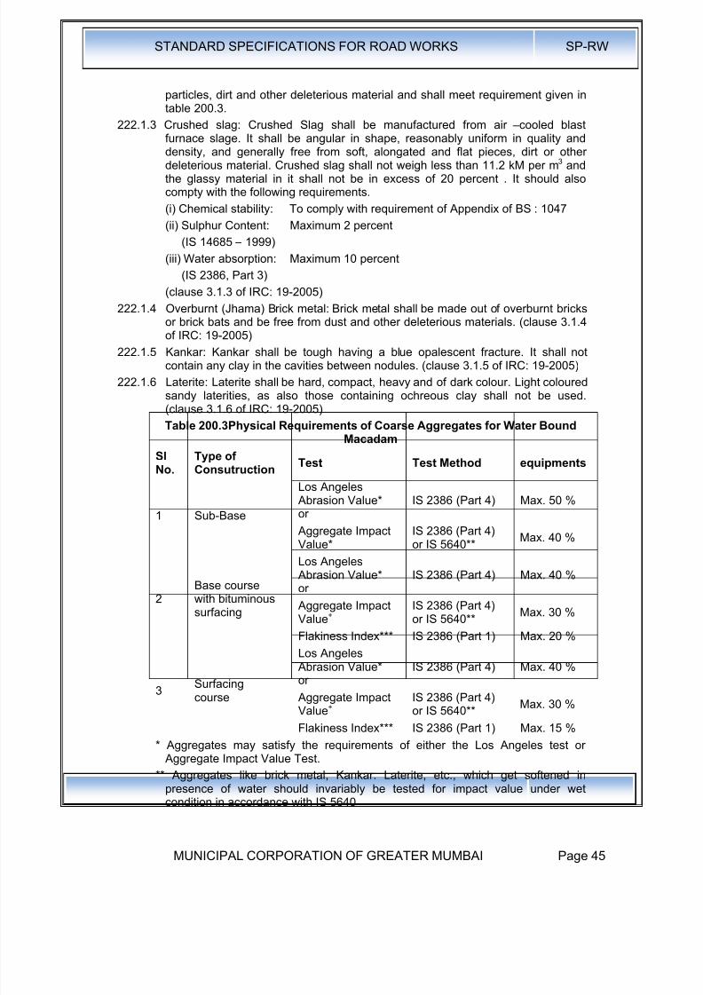
8/19/2019 MCGM Road Spec Volume -II
http://slidepdf.com/reader/full/mcgm-road-spec-volume-ii 49/176
STANDARD SPECIFICATIONS FOR ROAD WORKS SP-RW
MUNICIPAL CORPORATION OF GREATER MUMBAI Page 45
particles, dirt and other deleterious material and shall meet requirement given intable 200.3.
222.1.3 Crushed slag: Crushed Slag shall be manufactured from air –cooled blastfurnace slage. It shall be angular in shape, reasonably uniform in quality and
density, and generally free from soft, alongated and flat pieces, dirt or otherdeleterious material. Crushed slag shall not weigh less than 11.2 kM per m3 andthe glassy material in it shall not be in excess of 20 percent . It should alsocompty with the following requirements.
(i) Chemical stability: To comply with requirement of Appendix of BS : 1047
(ii) Sulphur Content: Maximum 2 percent
(IS 14685 – 1999)
(iii) Water absorption: Maximum 10 percent
(IS 2386, Part 3)
(clause 3.1.3 of IRC: 19-2005)
222.1.4 Overburnt (Jhama) Brick metal: Brick metal shall be made out of overburnt bricksor brick bats and be free from dust and other deleterious materials. (clause 3.1.4of IRC: 19-2005)
222.1.5 Kankar: Kankar shall be tough having a blue opalescent fracture. It shall notcontain any clay in the cavities between nodules. (clause 3.1.5 of IRC: 19-2005)
222.1.6 Laterite: Laterite shall be hard, compact, heavy and of dark colour. Light colouredsandy laterities, as also those containing ochreous clay shall not be used.(clause 3.1.6 of IRC: 19-2005)
Table 200.3Physical Requirements of Coarse Aggregates for Water BoundMacadam
Sl
No.
Type of
Consutruction
Test Test Method equipments
1 Sub-Base
Los Angeles Abrasion Value*or
IS 2386 (Part 4) Max. 50 %
Aggregate ImpactValue*
IS 2386 (Part 4)or IS 5640**
Max. 40 %
2Base coursewith bituminoussurfacing
Los Angeles Abrasion Value*or
IS 2386 (Part 4) Max. 40 %
Aggregate ImpactValue+
IS 2386 (Part 4)or IS 5640**
Max. 30 %
Flakiness Index*** IS 2386 (Part 1) Max. 20 %
3Surfacingcourse
Los Angeles Abrasion Value*or
IS 2386 (Part 4) Max. 40 %
Aggregate ImpactValue+
IS 2386 (Part 4)or IS 5640**
Max. 30 %
Flakiness Index*** IS 2386 (Part 1) Max. 15 %
* Aggregates may satisfy the requirements of either the Los Angeles test or Aggregate Impact Value Test.
** Aggregates like brick metal, Kankar. Laterite, etc., which get softened in
presence of water should invariably be tested for impact value under wetcondition in accordance with IS 5640
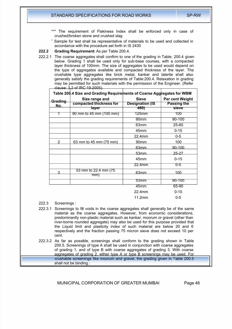
8/19/2019 MCGM Road Spec Volume -II
http://slidepdf.com/reader/full/mcgm-road-spec-volume-ii 50/176
STANDARD SPECIFICATIONS FOR ROAD WORKS SP-RW
MUNICIPAL CORPORATION OF GREATER MUMBAI Page 46
*** The requirement of Flakiness Index shall be enforced only in case ofcrushed/broken stone and crushed slag
+ Sample for test shall be representative of materials to be used and collected inaccordance with the procedure set forth in IS 2430
222.2 Grading Requirement: As per Table 200.4.222.2.1 The coarse aggregates shall confirm to one of the grading in Table: 200.4 given
below. Grading 1 shall be used only for sub-base courses, with a compactedlayer thickness of 100mm. The size of aggregates to be used would depend onthe type of aggregates available and compacted thickness of the layer. Thecrushable type aggregates like brick metal, kankar and laterite shall alsogenerally satisfy the grading requirements of Table:200.4. Relaxation in gradingmay be permitted for such materials with the permission of the Engineer. (Referclause: 3.2 of IRC:19-2005).
Table 200.4 Size and Grading Requirements of Coarse Aggregates for WBM
Grading
No.
Size range and
compacted thickness forlayer
Sieve
Designation (IS460)
Per cent Weight
Passing thesieve
1 90 mm to 45 mm (100 mm) 125mm 100
90mm 90-100
63mm 25-60
45mm 0-15
22.4mm 0-5
2 63 mm to 45 mm (75 mm) 90mm 100
63mm 90-100
53mm 25-27
45mm 0-15
22.4mm 0-5
353 mm to 22.4 mm (75
mm)63mm 100
53mm 90-100
45mm 65-90
22.4mm 0-10
11.2mm 0-5
222.3 Screenings :
222.3.1 Screenings to fill voids in the coarse aggregates shall generally be of the samematerial as the coarse aggregates. However, from economic considerations,predominantly non-plastic material such as kankar, moorum or gravel (other thanriver-borne rounded aggregate) may also be used for this purpose provided thatthe Liquid limit and plasticity index of such material are below 20 and 6respectively and the fraction passing 75 micron sieve does not exceed 10 percent.
222.3.2 As far as possible, screenings shall conform to the grading shown in Table200.5. Screenings of type A shall be used in conjunction with coarse aggregatesof grading 1, and of type B with coarse aggregates of grading 3. With coarseaggregates of grading 2, either type A or type B screenings may be used. Forcrushable screenings like moorum and gravel, the grading given in Table 200.5shall not be binding.:
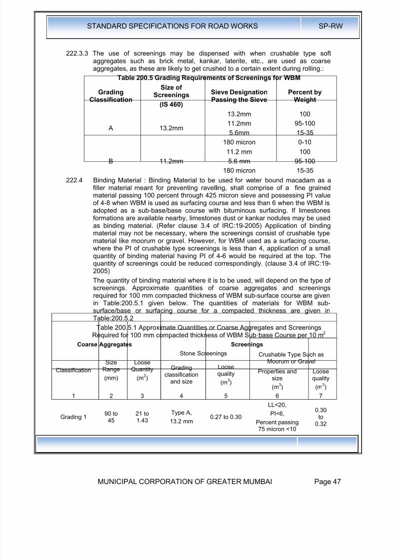
8/19/2019 MCGM Road Spec Volume -II
http://slidepdf.com/reader/full/mcgm-road-spec-volume-ii 51/176
STANDARD SPECIFICATIONS FOR ROAD WORKS SP-RW
MUNICIPAL CORPORATION OF GREATER MUMBAI Page 47
222.3.3 The use of screenings may be dispensed with when crushable type softaggregates such as brick metal, kankar, laterite, etc., are used as coarseaggregates, as these are likely to get crushed to a certain extent during rolling.:
Table 200.5 Grading Requirements of Screenings for WBM
GradingClassification
Size ofScreenings
(IS 460)
Sieve DesignationPassing the Sieve
Percent byWeight
A 13.2mm
13.2mm
11.2mm
5.6mm
180 micron
100
95-100
15-35
0-10
B 11.2mm
11.2 mm
5.6 mm
180 micron
100
95-100
15-35
222.4 Binding Material : Binding Material to be used for water bound macadam as afiller material meant for preventing ravelling, shall comprise of a fine grainedmaterial passing 100 percent through 425 micron sieve and possessing PI valueof 4-8 when WBM is used as surfacing course and less than 6 when the WBM isadopted as a sub-base/base course with bituminous surfacing. If limestonesformations are available nearby, limestones dust or kankar nodules may be usedas binding material. (Refer clause 3.4 of IRC:19-2005) Application of bindingmaterial may not be necessary, where the screenings consist of crushable typematerial like moorum or gravel. However, for WBM used as a surfacing course,where the PI of crushable type screenings is less than 4, application of a smallquantity of binding material having PI of 4-6 would be required at the top. The
quantity of screenings could be reduced correspondingly. (clause 3.4 of IRC:19-2005)
The quantity of binding material where it is to be used, will depend on the type ofscreenings. Approximate quantities of coarse aggregates and screeningsrequired for 100 mm compacted thickness of WBM sub-surface course are givenin Table:200.5.1 given below. The quantities of materials for WBM sub-surface/base or surfacing course for a compacted thickness are given inTable:200.5.2
Table 200.5.1 Approximate Quantities or Coarse Aggregates and ScreeningsRequired for 100 mm compacted thickness of WBM Sub·base Course per 10 m2
Coarse Aggregates Screenings
Classification
SizeRange
(mm)
LooseQuantity
(m2)
Stone Screenings Crushable Type Such asMoorum or Gravel
Gradingclassification
and size
Loosequality
(m3)
Properties andsize
(m3)
Loosequality
(m3)
1 2 3 4 5 6 7
Grading 190 to
4521 to1.43
Type A,
13.2 mm0.27 to 0.30
LL<20,
PI<6,
Percent passing75 micron <10
0.30to
0.32
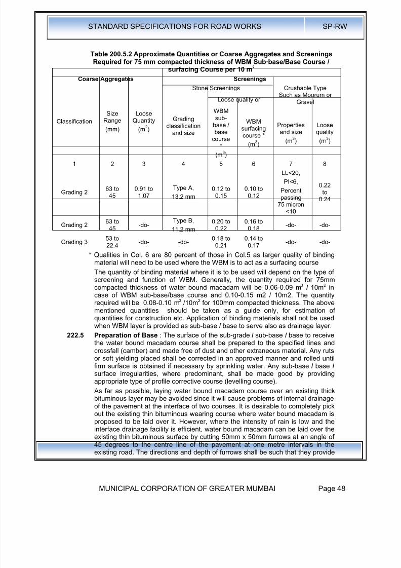
8/19/2019 MCGM Road Spec Volume -II
http://slidepdf.com/reader/full/mcgm-road-spec-volume-ii 52/176
8/19/2019 MCGM Road Spec Volume -II
http://slidepdf.com/reader/full/mcgm-road-spec-volume-ii 53/176
STANDARD SPECIFICATIONS FOR ROAD WORKS SP-RW
MUNICIPAL CORPORATION OF GREATER MUMBAI Page 49
adequate bondage and also serve to drain water to the existing granular basecourse beneath the existing thin bituminous surface.
Inverted Choke: If water bound macadam is to be laid directly over the sub-grade, without any other intervening pavement course, a 25mm course of
screenings (Grading B) or coarse sand shall be spread on the prepared sub-grade before application of the aggregates is taken up. In case of a fine sand orsilty or clayey sub-grade, it is advisable to lay 100mm insulating layer ofscreening or coarse sand on top of fine grained soil, the gradation of which willdepend upon whether it is intended to act as a drainage layer as well. As apreferred alternative to inverted choke, appropriate geosynthetic performingfunctions of separation and drainage may be used over the prepared sub-gradeas directed by the Engineer. Section 260 shall be applicable for use of geo-synthetics.
222.6 Spreading Coarse Aggregates : The coarse aggregates shall be spreaduniformly and evenly upon the prepared sub-grade I sub-base I base to properprofile by using templates placed across the road about 6m apart, in such
quantities that the thickness of each compacted layer is not more than 75mm asspecified in Clause 222.2 Wherever possible, approved mechanical devices suchas aggregate spreader shall be used to spread the aggregates uniformly so as tominimize the need for manual rectification afterwards. Aggregates placed atlocations which are inaccessible to the spreading equipment, may be spread inone or more layers by any approved means so as to achieve the specifiedresults.
The spreading shall be done from stockpiles along the side of the roadway ordirectly from vehicles. No segregation of large or fine aggregates shall beallowed and the coarse aggregate as spread shall be of uniform gradation withno pockets of fine material.
The surface of the aggregates spread shall be carefully checked with templatesand all high or low spots remedied by removing or adding aggregates as may berequired. The surface shall be checked frequently with a straight edge whilespreading and rolling so as to ensure a finished surface as per approveddrawings.
The coarse aggregates shall normally be spread more than 3 days in advance ofthe subsequent construction operations.
222.7 Roller : If the thickness of single layer does not exceed 100mm a smoothwheeled Roller of 80-100 KN weight be used. For a compacted single layer upto200mm, the compaction shall be done with the help of vibratory Roller ofminimum static weight of 80-100 KN.
222.8 Rolling: Immediately following the spreading of the coarse aggregate, rollingshall be started with three wheeled power rollers of 80 to 100 KN capacity ortandem or vibratory rollers of 80 to 100 KN static weight. The type of roller to beused shall be approved by the Engineer based on trial run.
Except on super-elevated portions where the rolling shall proceed from inneredge to the outer, rolling shall begin from the edges gradually progressingtowards the centre. First the edge / edges shall be compacted with roller runningforward and backward. The roller shall then move inward parallel to the centreline of the road, in successive passes uniformly lapping preceding tracks by atleast one half widths. Rolling shall be discontinued when the aggregates arepartially compacted with sufficient void space in them to permit application ofscreenings. Compaction shall be continued until the aggregates are thoroughly
keyed. During rolling, slight sprinkling of water may be done, if necessary. Rollingshall not be done when the sub-grade is soft or yielding or when it causes a
8/19/2019 MCGM Road Spec Volume -II
http://slidepdf.com/reader/full/mcgm-road-spec-volume-ii 54/176
STANDARD SPECIFICATIONS FOR ROAD WORKS SP-RW
MUNICIPAL CORPORATION OF GREATER MUMBAI Page 50
wave-line motion in the sub-grade or sub-base course. If irregularities developduring rolling, which exceed 12 mm when tested with a 3 m straight edge, thesurface shall be loosened and aggregates added or removed as required beforerolling again so as to achieve all uniform surface conforming to the desired crosssection and grade. (Refere clause 4.4.4 of IRC:19- 2005)-
The rolled surface shall be checked transversely and longitudinally, withtemplates and any irregularities corrected by loosening the surface, adding orremoving necessary amount of aggregates and rerolling until the entire surfaceconforms to desired cross fall (camber) and grade. In no case shall the use ofscreenings be permitted to make up depressions.
Material which gets crushed excessively during compaction or becomessegregated shall be removed and replaced with suitable aggregates.
222.9 Application of Screenings : After the coarse aggregate has been rolled toClause 222.9 screenings to completely fill the interstices shall be appliedgradually over the surface. These shall not be damp or wet at the time ofapplication. Dry rolling shall be done while the screenings are being spread so
that vibrations of the roller cause them to settle into the voids of the coarseaggregate. The screenings shall not be dumped in piles but be spread uniformlyin successive thin layers either by the spreading motions of hand shovels or bymechanical spreaders, or directly from tipper with suitable grit spreadingarrangement. Tipper operating for spreading the screenings shall be so driven asnot to disturb the coarse aggregate.
The screenings shall be applied at a slow and uniform rate (in three or moreapplications) so as to ensure filling of all voids. This shall be accompanied by dryrolling and brooming with mechanical brooms, hand-brooms or both. In no caseshall be the screenings be applied so fast and thick as to form cakes or ridges onthe surface in such a manner as would prevent filling of voids or prevent the
direct bearing of the roller on the coarse aggregate. These operations shallcontinue until no more screenings can be forced into the voids of the coarseaggregate.
The spreading, rolling and brooming of screenings shall be carried out in onlysuch lengths of the road which could be completed within one day's operation.
222.10 Sprinkling of Water and Grouting : After the screenings have been applied, thesurface shall be copiously sprinkled with water, swept and rolled. Hand broomsshall be used to sweep the wet screenings into voids and to distribute themevenly. The sprinkling, sweeping and rolling operation shall be continued, withadditional screenings applied as necessary until the coarse aggregate has beenthoroughly keyed, well-bonded and firmly set in its full depth and a grout hasbeen formed of screenings. Care shall be taken to see that the base or sub-grade does not get damaged due to the addition of excessive quantities of waterduring construction. .
In case of lime treated soil sub-base, construction of water bound macadam ontop of it can cause excessive water to flow down to the lime treated sub-basebefore it has picked up enough strength (is still "green") and thus cause damageto the sub-base layer. The laying of water bound macadam layer in such casesshall be done after the subbase attains adequate strength, as directed by theEngineer.
222.11 Application of Binding Material: After the application of screenings inaccordance with Clauses 222.10 the binding material where it is required to beused (Clause 222.4) shall be applied successively in two or more thin layers at a
slow and uniform rate. After each application, the surface shall be copiouslysprinkled with water, the resulting slurry swept in with hand brooms, or
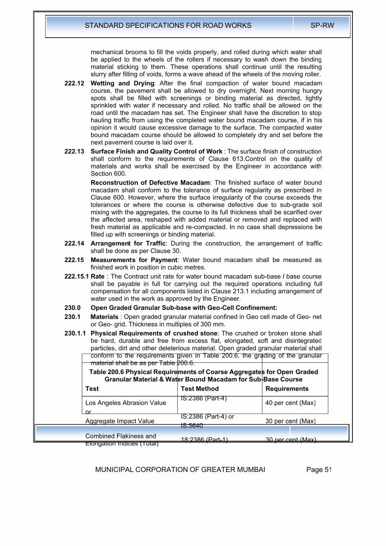
8/19/2019 MCGM Road Spec Volume -II
http://slidepdf.com/reader/full/mcgm-road-spec-volume-ii 55/176
8/19/2019 MCGM Road Spec Volume -II
http://slidepdf.com/reader/full/mcgm-road-spec-volume-ii 56/176
STANDARD SPECIFICATIONS FOR ROAD WORKS SP-RW
MUNICIPAL CORPORATION OF GREATER MUMBAI Page 52
230.1.2 Grading Requirements: As in Table 200.4
230.1.3 Geo-Cell : Geo-net or Geo-Grid of design strength shall provide open gradedaggregate of sub-base with confinement, the thickness of layer shall be as perthe design. The geo-net or geo-grid shall be laid in vertical plain, in zigzag
,pattern and tied at the nodes forming compartment or cells of designeddiameter. The spacing of the geo-net or geo-grid shall be not more than 1.2times the depth of the geo-cell. Geo-net, Geo-grid is as per Clause No. 260.
230.1.4 Geo-Textile : Geo-Textile shall be as per the specifications given in Clause No.260
230.1.5 Laying : Layer of Geo-Textile shall be provided at bottom on the prepared sub-grade. The Geo-cell shall be laid on the geo-membrane. The nodes shall be tiedas per manufacturer's directions. The cells so formed are then filled to the fulldepth as one layer.
230.1.6 Rolling as single layer with 80-100 KN smooth wheeled Roller and 60-80 KNstatic weight vibratory Roller.
230.1.7 Measurements for Payment : The geo-textile and geo-cell shall be measured perSquare Metre of the sub-base as laid. Measurement for the aggregate shall beas per WBM given in Clause No.220.
230.1.8 Rates : Rates shall be per 8quare Metre of the sub-base area for geo-cell andgeo-membrane and as per Clause No.220 for aggregate.
235.0 Crushed Cement Concrete
235.1 Scope : This work shall consist of breaking and crushing the damaged cementconcrete slabs and re-compacting the same as sub-base/base course in one ormore layers. Where specified, it shall also include treating the surface of the toplayer with a penetration cot of bitumen. The work shall be performed on suchwidths and lengths as may be specified, in accordance with the requirements of
these Specifications and in conformity with the lines, grades and cross-sectionsshown on :the drawings or as otherwise directed by the Engineer.
235.2 Materials:
235.2.1 Coarse Aggregate : Coarse Aggregate for this work shall be broken cementconcrete slabs crushed to a size not exceeding 75mm and as far as possible,conforming to one of the gradings given in Table 200.4.
235.2.2 Key Aggregate: Key Aggregate for the penetration coat shall consist of crushedstone, crushed gravel, shingle or other stones. It shall be clean, strong, durable,of fairly cubical shape and free of disintegrated pieces, organic or otherdeleterious matter and adherent coatings. The aggregate shall be hydrophobicand of low porosity.
The aggregate shall be of 11.2mm size defined as 100 per cent passing through13.2mm sieve and retained on 5.6mm sieve and shall satisfy the physicalrequirements set forth in Table 200-5.
235.2.3 Binder : Binder for the penetration coat for the top layer shall be bitumen of asuitable grade, as directed by the Engineer and satisfying the requirements of18:73, 217 or 454, as applicable or any approved cutback or emulsion satisfyingthe requirements of 18:8887.
235.2.4 Construction Operations
235.2.5 General: Crushed cement concrete sub-base/base course may be constructed inone or two layers, depending upon the thickness of the concrete slabsdismantled and crushed. The thickness of each layer shall, however, not exceed
100 mm in case of sub-base and 75mm in case of base course.

8/19/2019 MCGM Road Spec Volume -II
http://slidepdf.com/reader/full/mcgm-road-spec-volume-ii 57/176
STANDARD SPECIFICATIONS FOR ROAD WORKS SP-RW
MUNICIPAL CORPORATION OF GREATER MUMBAI Page 53
The course shall be constructed as water bound macadam to Clause 220, usingcrushed cement concrete as coarse aggregate except that no screenings orbinding material need be applied. Where specified, the top layer shall be treatedwith a penetration coat of binder described in Clause 235.2.6.
235.2.6 Application of penetration coat over the top layer: Before the application of thepenetration coat, the surface shall be cleaned of dust, dirt and other foreignmatter, using mechanical broom or any other equipment specified by theEngineer. Dust removed in the process shall be blown off with the help ofcompressed air.
The binder shall be heated to the temperature appropriate to the grade ofbitumen used and sprayed on the dry surface in a uniform manner at the rate of25 Kg per 10 sq. m area in terms of the residual bitumen with the help of eitherself-propelled or towed bitumen pressure sprayer with self-heating arrangementand spray nozzle capable of spraying bitumen at specified rates andtemperatures so as to provide a uniform, unbroken spread of bitumen. Excessivedeposits of binder caused by stopping or staring of the sprayer or through
leakage or any other reason shall be suitably corrected.Immediately after the applicable of binder, the key aggregates, in a clean and drystate shall be spread uniformly on the surface at the rate of 0.13 Cu. M. per 10sq.m area, preferably by means of a mechanical grader, capable of spreadingaggregate uniformly at specified rates or otherwise manually with the approval ofthe Engineer, so as to cover the surface completely. Immediately after theapplication of the key aggregates, the entire surface shall rolled to Clause352.4.4.
235.2.7 Surface Finish and Quality Control of Works : The surface finish of constructionshall conform to the requirements of Clause 600.Control on the quality ofmaterial and works shall be exercised by the Engineer in accordance with
Section 600.235.2.8 Arrangements for Traffic: During the period of construction, arrangement of traffic
shall be done as per Clause 30.
235.2.9 Measurements for Payment: Breaking the existing cement concrete pavementslabs, crushing and re-compacting the slab material as sub-base/ base courseshall be measured as a single item in terms of the volume of sub-base/base laidin position in cubic metres. Penetration coat shall be measured as finished workin square metres.
235.2.10 Rates:
235.2.10.1 The Contract unit rate for crushed cement concrete sub-base/base courseshall be payment in full for carrying out the required operations including full
compensation for:a) making arrangements for traffic to Clause 30 except for initial treatment to
verges I shoulders and construction of diversions;
b) breaking the cement concrete slabs, crushing, sieving and re-compactingthe slab material as sub-base/base course;
c) all labour, tools, equipment and incidentals to complete the work to theSpecifications; and
d) carrying out the work in part widths of road where directed. 235.2.10.2 TheContract unit rate for penetration coat shall be payment in full for carryingout the required operations including full compensation for all componentslisted in Clause 504.8.
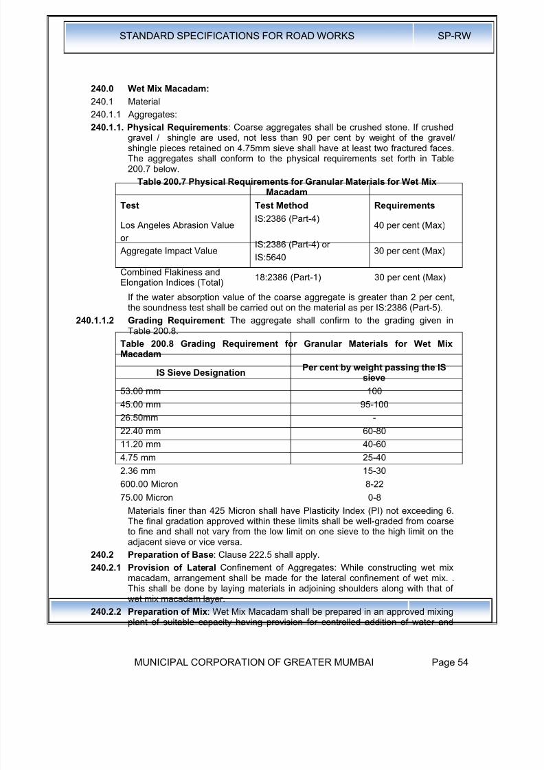
8/19/2019 MCGM Road Spec Volume -II
http://slidepdf.com/reader/full/mcgm-road-spec-volume-ii 58/176
STANDARD SPECIFICATIONS FOR ROAD WORKS SP-RW
MUNICIPAL CORPORATION OF GREATER MUMBAI Page 54
240.0 Wet Mix Macadam:
240.1 Material
240.1.1 Aggregates:
240.1.1. Physical Requirements: Coarse aggregates shall be crushed stone. If crushedgravel / shingle are used, not less than 90 per cent by weight of the gravel/shingle pieces retained on 4.75mm sieve shall have at least two fractured faces.The aggregates shall conform to the physical requirements set forth in Table200.7 below.
Table 200.7 Physical Requirements for Granular Materials for Wet MixMacadam
Test Test Method Requirements
Los Angeles Abrasion Value
or
Aggregate Impact Value
IS:2386 (Part-4)
IS:2386 (Part-4) orIS:5640
40 per cent (Max)
30 per cent (Max)
Combined Flakiness andElongation Indices (Total)
18:2386 (Part-1) 30 per cent (Max)
If the water absorption value of the coarse aggregate is greater than 2 per cent,the soundness test shall be carried out on the material as per IS:2386 (Part-5).
240.1.1.2 Grading Requirement: The aggregate shall confirm to the grading given inTable 200.8.
Table 200.8 Grading Requirement for Granular Materials for Wet MixMacadam
IS Sieve Designation Per cent by weight passing the ISsieve
53.00 mm 100
45.00 mm 95-100
26.50mm -
22.40 mm 60-80
11.20 mm 40-60
4.75 mm 25-40
2.36 mm 15-30
600.00 Micron 8-2275.00 Micron 0-8
Materials finer than 425 Micron shall have Plasticity Index (PI) not exceeding 6.The final gradation approved within these limits shall be well-graded from coarseto fine and shall not vary from the low limit on one sieve to the high limit on theadjacent sieve or vice versa.
240.2 Preparation of Base: Clause 222.5 shall apply.
240.2.1 Provision of Lateral Confinement of Aggregates: While constructing wet mixmacadam, arrangement shall be made for the lateral confinement of wet mix. .This shall be done by laying materials in adjoining shoulders along with that ofwet mix macadam layer.
240.2.2 Preparation of Mix: Wet Mix Macadam shall be prepared in an approved mixingplant of suitable capacity having provision for controlled addition of water and

8/19/2019 MCGM Road Spec Volume -II
http://slidepdf.com/reader/full/mcgm-road-spec-volume-ii 59/176
STANDARD SPECIFICATIONS FOR ROAD WORKS SP-RW
MUNICIPAL CORPORATION OF GREATER MUMBAI Page 55
forced / positive mixing arrangement like pugmill or pan type mixer of concretebatching plant. For small quantity of wet mix work, the Engineer may permit themixing to be done in concrete mixers.
Optimum moisture for mixing shall be determined in accordance with 15:2720
(Part-8) after replacing the aggregate fraction retained on 22.4mm sieve withmaterial of 4.75mm to 22.4mm size. While adding water, due allowance shouldbe made for evaporation losses. However, at the time of compaction, water in thewet mix should not vary from the optimum value by more than agreed limits. Themixed material should be uniformly wet and no segregation should be permitted
240.2.3 Spreading of Mix: Immediately after mixing, the aggregates shall be spreaduniformly and evenly upon the prepared sub-grade/ sub-base I base in requiredquantities. In no case should these be dumped in heaps directly on the areawhere these are to be .Iaid nor shall their hauling over a partly completed stretchbe permitted.
The mix may be spread either by a pave finisher or motor grader. For portionswhere mechanical means cannot be used, manual means as approved, by the
Engineer shall be used. The motor grader shall be capable of spreading thematerial uniformly all over the surface. Its blade shall have hydraulic controlsuitable for initial adjustments and maintaining the same so as to achieve thespecified slope and grade.
The paver finisher shall be self-propelled, having the following features:
a) Loading hoppers and suitable distribution mechanism
b) The screed shall have tamping and vibrating arrangement for initialcompaction to the layer as it is spread without rutting or otherwise marringthe surface profile.
c) The paver shall be equipped with necessary control mechanism so as toensure that the finished surface is free from surface blemishes.
The surface of the aggregate shall be carefully checked with templates and allhigh or low spots remedied by removing or adding aggregate as may berequired. The layer may be tested by depth blocks during construction. Nosegregation of larger and fine particles should be allowed. The aggregates asspread should be of uniform gradation with no pockets of fine materials.
240.2.4 Compaction: After the mix has been laid to the required thickness, grade andcross fall I camber the same shall be uniformly compacted, to the full depth withsuitable roller. If the thickness of single compacted layer does not exceed100mm, a smooth wheel roller of 80 to 100 kN weight may be used. For acompacted single layer upto 200mm, the compaction shall be done with the helpof vibratory roller of minimum static weight of 100 to 200 kN or equivalent
capacity roller. The speed of the roller shall not exceed 5 Km/H.In portions having unidirectional cross fall / super elevation, rolling shallcommence from the lower edge and progress gradually towards the upper edge.Thereafter, roller should progress parallel to the centre line of the road, uniformlyover-lapping each preceding track by at least one third width until the entiresurface has been rolled. Alternate trips of the roller shall be terminated in stopsat least 1 m away from any preceding stop.
In portions in camber, rolling should begin at the edge with the roller runningforward and backward until the edges have been firmly compacted. The rollershall then progress gradually towards the centre parallel to the centre line of theroad uniformly overlapping each of the preceding tracks by at least one-third
width until the entire surface has been rolled.
8/19/2019 MCGM Road Spec Volume -II
http://slidepdf.com/reader/full/mcgm-road-spec-volume-ii 60/176

8/19/2019 MCGM Road Spec Volume -II
http://slidepdf.com/reader/full/mcgm-road-spec-volume-ii 61/176
STANDARD SPECIFICATIONS FOR ROAD WORKS SP-RW
MUNICIPAL CORPORATION OF GREATER MUMBAI Page 57
260.0 Geo-Synthetic Fabric
261.0 Geo-Synthetic: Geo-Synthetic is .a general classification for all syntheticmaterials used in geo-technical engineering application. It includes geo-textiles,
geo-grids, geo-nets, geo-membranes and geo-composites.262.0 Geo-Textiles : Any permeable textile natural or synthetic, used with foundation,
soil, rock, earth, or any other geo-technical engineering related material. In thepresent specifications, it is related to synthetic material only.
Geo-textile shall be made of polyethylene or polypropylene or polyester or similarfibres, either woven or non-woven in variety, through machine made process ofheat bonding or needle punching or weaving' techniques. These fabrics arerequired to pass water through but retain the soil particles, which require specificcross-plant permeability or permittivity and apparent opening size or equivalentopening size of 0.095mm. The above two requirements along with therequirement of strength and durability denote general characteristics of geo-
textiles to be used. The type of geo-textile to be used in a particular applicationshall be decided on the basis of design.
The physical properties include specific gravity, mass per unit area, thickness.The mechanical properties include tensile strength (machine direction, cross Mdirection) strain at failure, modulus, fatigue strength, puncture strength; frictionand creep. Environmental properties include resistance to chemicals,temperature, light & weather, bacteria and design life.
263.0 Geo-Grid : A deformed or non-deformed grid of polymeric material used primarilyfor reinforcement purposes with foundation, soil, rock, earth, or any other geo-technical engineering related material.
Geo-Grid shall be made from integrally jointed, mono or bi-directionally
orientated or stretched meshes made from polyethylene or polypropylene orpolyester or similar polymer, with high secant modulus, in square, rectangular,hexagonal or oval mesh form. Their junction strength shall be high with highcreep resistance, and dimensional stability. Their open structure shall permiteffective interlocking with soil, aggregates, rock, etc., they shall be used as atensile member or reinforcement. Characteristic strength at a maximumelongation of 15 per cent in the direction of the length of the roll. The physicalproperties include mass per unit area, thickness at rib & junction and polymertype. The mechanical properties shall include peak tensile strength, yield pointelongation, tensile strength at 2% strain & 5% strain.
264.0 Geo-Net : These are net made of polymeric material used for drainage offoundation, soil, rock, earth or any other geo-technical engineering related
material.Geo-Net shall be made from a single extruded un-oriented process frompolyethylene or polypropylene 'or similar polymer. It shall have square orrectangular net shape aperture when used for protective works like gabions andmattresses. While in polygonal aperture, it shall be used as a separator. It shallnot be used as soil reinforcement due to its high creep characteristics, neither asa slope reinforcement or soil retaining wall or asphaltic reinforcement. Geo-netsused in protective works for highway structures shall be at least 650 Gm. / sq. min unit weight. It shall be black in colour, available in roll form in suitable width.
265.0 Geo-Membrane : An essentially impermeable membrane of polymeric materialused with foundation, soil, rock, earth or any other geotechnical engineering be
made from PVC or polyethylene sheets of at least 0.8mm thickness, dulyprotected from ultra-violet exposure with 2.5 per cent carbon black, in black
8/19/2019 MCGM Road Spec Volume -II
http://slidepdf.com/reader/full/mcgm-road-spec-volume-ii 62/176
STANDARD SPECIFICATIONS FOR ROAD WORKS SP-RW
MUNICIPAL CORPORATION OF GREATER MUMBAI Page 58
colour, supplied in roll form with 3m or above width. The joints of these sheetsshall be heat bonded or seamed for effective permeation cut off, at site usingstandard equipment as part of the laying process. While fixing on to a slope, theyshall not be punctured or stapled to impair their use. The physical propertiesinclude thickness, specific gravity and mass per unit area. The mechanicalproperties shall include tensile strength at yield, elongation at yield, modulus ofelasticity, tear resistance, impact resistance ,puncture resistance, soil to linerfriction
266.0 Geo-Composite : A manufactured material using geo-textiles, geogrids, geo-nets and / or geo-membrane in laminated or composite form. Geo-Compositesshall be made from combination of geo-nets, geogrids, or geo-membranes ofabove description using heat bonded, seamed, stitched or wrap techniques.Their principal use shall be to regulate drainage in cross,.plane or in-planedirections. Minimum unit weight of such material shall conform to the specialprovisions or as per Contract drawing. .
267.0 The placement of Geo-synthetic shall conform to manufacturer's specifications.
The contractor shall submit to the engineer the complete design & scheme ofinstallation - the particular brand and its properties equipment and methodologyto be used for installation.
268.0 The payment shall be as per area covered. No separate payment shall be madefor laps.
269.0 The rate shall be per square meter of geo-synthetic installed.

8/19/2019 MCGM Road Spec Volume -II
http://slidepdf.com/reader/full/mcgm-road-spec-volume-ii 63/176
STANDARD SPECIFICATIONS FOR ROAD WORKS SP-RW
MUNICIPAL CORPORATION OF GREATER MUMBAI Page 59
300.0 Bituminous Mixes
301.0 Properties of Bitumen
301.1 Density: Density is the unit weight of a given bituminous mix. This gives anindication· of the bitumen content in the designed mix and helps to establish thebasis for controlling/determination of compaction during construction. Densitiesof specimens obtained from pavements determine the effectiveness of rolling.
301.2 Ductility: Ductility is an indication of the extension or stretch ability of bitumenunder standard conditions. A small briquette of bitumen of a given dimension at astandard test condition is pulled in an apparatus at a standard rate of speed untilthe thread of bitumen breaks. The length of the pull measured in centimeters isdesignated as ductility of the bitumen sample under test.
301.3 Flash point : Flash point is the minimum temperature at which bitumen gives aninstantaneous flash in the presence of an external open flame.
301.4 Penetration: Penetration determines the relative hardness or consistency ofbitumen by measuring the distance that a standard needle will penetratevertically into a sample of bitumen at 25°C under a load of 100 grams applied for5 seconds.
301.5 Softening point: Softening point is the temperature at which a standard quantityof bitumen will become fluid. It is usually tested by a ball/ring test method.
301.6 Solubility: The portion of bitumen which fully dissolves in carbon tetrachloriderepresents the actual binder material in the bitumen sample.
301.7 Thin film oven test: This test indicates the amount of hardness that may beexpected to occur in bitumen during plant mixing. The tendency to harden ismeasured as a percentage of penetration after and before the thin film oven test.50 grams of the sample is held in a standard size cup, rotated on a shelf inside awell ventilated oven maintained at 165°C for 5 hours. Penetration is taken beforeand after the test.
301.8 Viscosity: Viscosity of bitumen determines the flow characteristics of bitumen ata given temperature. It is measured by Saybolt Furol or using Brookfield DV-IIapparatus and is stated in the seconds or in Poise.
302.0 Properties of Bituminous Mixes:
302.1 Voids: Determination of voids in a compact specimen of paving mixture is doneby checking the specific gravity of aggregate and the specific gravity of bitumenused.
302.2 Bleeding: The exudation of bituminous material on a roadway surface afterconstruction.
302.3 Blinding: A covering of stone ships, sand or other suitable material applied to aroad surface after an application of asphalt.
302.4 Corrugations- Ripples, waves or uniform undulations which are liable to appearin all types of road surfaces.
302.5 Foam - The condition of hot asphalt cement caused by rain or water getting intothe hot bitumen and causing excessive building up of small steam bubbles.
302.6 Greedy- Applied to an aggregate or surface which will absorb a large quantity ofbituminous binding material.
302.7 Hot laid mixtures - Plant mixes of bitumen and aggregates which must bespread and compacted while in a heated condition. They are prepared withbituminous cements and lose their workability when cooled to atmosphere
temperature. The following thumb rules have been evolved on normal pavingbitumen on hot laid mixtures:
8/19/2019 MCGM Road Spec Volume -II
http://slidepdf.com/reader/full/mcgm-road-spec-volume-ii 64/176
STANDARD SPECIFICATIONS FOR ROAD WORKS SP-RW
MUNICIPAL CORPORATION OF GREATER MUMBAI Page 60
Blue smoke from the mix : OverheatingSteam from the mix : Too much moistureDistribution of bitumen on aggregate not uniform: Mixing temp too lowMix looks stiff and dull rather than black and shiny: Deficiency bitumen
Mix lies slumped on the floor : Excessive bitumen302.8 Lean: Containing a deficiency of bituminous material or conversely containing
excess of aggregate.
302.9 Adhesion of bitumen: Bitumen has excellent adhesive qualities provided theconditions are favorable. However in presence of water the adhesion does createsome problems. Most of the aggregates used in road construction possess aweak negative charge on the surface. The bitumen aggregate bond is because ofa weak dispersion force. Water is highly polar and hence it gets strongly attachedto the aggregate displacing the bituminous coating.
TABLE 301.1 PROPERTIES OF VARIOUS GRADES OF BITUMEN (PAVINGBITUMEN)
SrNo.
Characteristics Grades and Requirements80/100 60/70 30/40
1 Specific gravjty at 27° C, min 0.99 0.99 0.99
2 Water percent by mass, max 0.2 0.2 0.2
3Flash point, Cleveland open cup,oC min.
175 175 175
4 Softening Point oC 35 to 50 40 to 55 50 to 65
5Penetration at 25oC, 100g, 5 sec.,1/10 mm
80 to 100 60 to 70 30 to 40
6 Penetration ratio, min. 35 35 35
7 Ductility at 27°C, in cm, min. 75 75 50
8Paraffin wax content, percent bymass, max
4.5 4.5 4.5
9 Frass break point, °c min -8 -6 -4
10Loss on heating, thin film ovenmax, test, percent by mass
1 1 1
11Retained penetration after thinfilm oven test, 25°C 100 g, 5sec.,1/10 mm, percent of original, min
47 52 55
12
Matter soluble in
Trichloroethylene, percent bymass, min
99 99 99
13 Viscosity at
(a)600, Poises 500±100 1000±200 2500±500
(b )135 oC, cSt, min 110 150 220
303.0 Types of Bitumen: Bitumen or bituminous binders available in India arespecified in IS: 73-1992 and industrial bitumen are specified in IS: 702 - 1988. Itis a viscous liquid or a solid consisting essentially of hydrocarbons and theirderivatives soluble in Trichloroethylene. These are substantially non voltaic andsoften gradually when heated. These are obtained by refinery process fromcrude petroleum.
There are two types of bitumen:-
8/19/2019 MCGM Road Spec Volume -II
http://slidepdf.com/reader/full/mcgm-road-spec-volume-ii 65/176
STANDARD SPECIFICATIONS FOR ROAD WORKS SP-RW
MUNICIPAL CORPORATION OF GREATER MUMBAI Page 61
i. Paving bitumen from non waxy crude referred as Type S
ii. Paving Bitumen from waxy crude referred as Type A
These are generally referred to based on the penetration characteristic as:
(i) S 35, S 45, S 65, S 90, S 200
(ii) A 35, A 55, A 65, A 90
Paving bitumen is further classified as
(a) Conventional paving binder bitumen
(b) Bitumen emulsions
(c). Cutback bitumen
(d) Modified bitumen
304.0 GRADES OF BITUMEN GENERALLY IN USE ON ROADS
The different grades of paving bitumen are described further:
304.1 Bitumen 80/100 (90): The characteristics of this grade conform to that of S-90grade of IS: 73-1992.
304.2 Bitumen 60/70 (65): The characteristics of this grade conform to that of S-65grade of IS: 73-1992. 60170 grade is harder in comparison to 80/100 grade andis used mainly in construction of National Highways & State Highways and in hotclimate areas.
304.3 Bitumen 30/40: The characteristics of this grade conform to that of S- 35 gradeof IS:73 -1992. Bitumen 30/40 is used in specialized applications like airportrunway construction as this grade is harder than 60/70 grade.
305.0 Bitumen Emulsion: Bitumen emulsion is a free flowing liquid at ambienttemperatures. Bitumen emulsion is a stable dispersion of fine globules ofbitumen in continuous water phase. Dispersion is obtained by processingbitumen and water under controlled conditions through a colloidal mill togetherwith selected additives. The use of proper quality and quantity of emulsifiers isessential to ensure that the emulsion has stability over time and also that itbreaks and sets when applied on aggregates/road surface.
305.1 Emulsions: Different Types of Emulsion and their application are given infollowing Table
Table 301.2 Types of Bitumen Emulsions and their Application
Type Application
Rapid SettingThese emulsions are suitable for singlecoat or two coat surface dressing Tackcoat etc
Medium Setting Applicable to premix carpet, patch workand pot hole filling
Slow SettingSuitable for recycling prime coat, slurrysealing, dense and semi-dense coldmixes, mix seal surfacing,
Polymer Modified Bitumen EmulsionSuitable for chip-sealing and microsurfacing
The recommended uses of emulsified bitumen of cationic type suggested are asfollows:
RS-1 Tack coat applications
RS-2 Surfacing dressing work
MS Premix carpet, patch work

8/19/2019 MCGM Road Spec Volume -II
http://slidepdf.com/reader/full/mcgm-road-spec-volume-ii 66/176
STANDARD SPECIFICATIONS FOR ROAD WORKS SP-RW
MUNICIPAL CORPORATION OF GREATER MUMBAI Page 62
SS-1 Fog seal, Crack sealing, Prime coat applications
Physical and chemical requirements of bitumen emulsion (cationic type) is given intable
Table 301.3 Physical and Chemical requirements of Bitumen Emulsion
SINo
CharacteristicsType of Emulsion
RS-1 RS-2 MS SS-1 SS-2
1Residue on 600 micronIS Sieve (Percent bymass, Max)
0.05 0.05 0.05 0.05 0.05
2
Viscosity by Saybolt Furol
Viscometer, second
At 25 oC - - - 20-10030-150
At 50°C 20-100 100-300 50-300 - -
3Coagulation of emulsionat low temperature*
Nil Nil Nil Nil Nil
4Storage stability after 24h
, 2 1 1 2 2
5 Particle charge Positive PositivePositiv
e
WeakPositiv
e
Positive
6
Coating ability and waterResistance
Coating, dry aggregate - - Good - -
Coating, after spraying - - Fair - -
Coating, wet aggregate - - Fair - -
Coating after spraying - - Fair - -
7
Stability to mixing withCement
(Percentage ,.coagulation )Max
- - - 2 2
8 Miscibility with water
No
coagulation
No
coagulation
No
coagulation
No
coagulation
Nocoag
ulation
9
Tests of residue:
a)Residue byevaporation, Percent, Min
60 67 65 50 60
b) Penetration 250C/100g/5 sec
80-150 80-150 60-150 60-35060-120
c) Ductility 270C/cm, Min 50 50 50 50 50
d)Solubility:lntrichloroethylene, Min
98 98 98 98 98
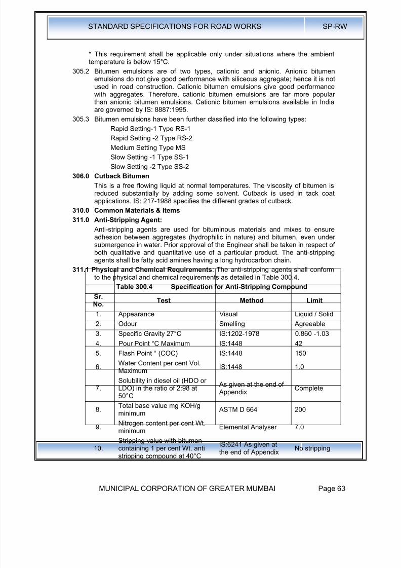
8/19/2019 MCGM Road Spec Volume -II
http://slidepdf.com/reader/full/mcgm-road-spec-volume-ii 67/176
STANDARD SPECIFICATIONS FOR ROAD WORKS SP-RW
MUNICIPAL CORPORATION OF GREATER MUMBAI Page 63
* This requirement shall be applicable only under situations where the ambienttemperature is below 15°C.
305.2 Bitumen emulsions are of two types, cationic and anionic. Anionic bitumenemulsions do not give good performance with siliceous aggregate; hence it is not
used in road construction. Cationic bitumen emulsions give good performancewith aggregates. Therefore, cationic bitumen emulsions are far more popularthan anionic bitumen emulsions. Cationic bitumen emulsions available in Indiaare governed by IS: 8887:1995.
305.3 Bitumen emulsions have been further classified into the following types:
Rapid Setting-1 Type RS-1
Rapid Setting -2 Type RS-2
Medium Setting Type MS
Slow Setting -1 Type SS-1
Slow Setting -2 Type SS-2
306.0 Cutback Bitumen
This is a free flowing liquid at normal temperatures. The viscosity of bitumen isreduced substantially by adding some solvent. Cutback is used in tack coatapplications. IS: 217-1988 specifies the different grades of cutback.
310.0 Common Materials & Items
311.0 Anti-Stripping Agent:
Anti-stripping agents are used for bituminous materials and mixes to ensureadhesion between aggregates (hydrophilic in nature) and bitumen, even undersubmergence in water. Prior approval of the Engineer shall be taken in respect ofboth qualitative and quantitative use of a particular product. The anti-strippingagents shall be fatty acid amines having a long hydrocarbon chain.
311.1 Physical and Chemical Requirements: The anti-stripping agents shall conformto the physical and chemical requirements as detailed in Table 300.4.
Table 300.4 Specification for Anti-Stripping Compound
Sr.No.
Test Method Limit
1. Appearance Visual Liquid / Solid
2. Odour Smelling Agreeable
3. Specific Gravity 27°C IS:1202-1978 0.860 -1.03
4. Pour Point °C Maximum IS:1448 42
5. Flash Point ° (COC) IS:1448 150
6.Water Content per cent Vol.Maximum
IS:1448 1.0
7.Solubility in diesel oil (HDO orLDO) in the ratio of 2:98 at50°C
As given at the end of Appendix
Complete
8.Total base value mg KOH/gminimum
ASTM D 664 200
9.Nitrogen content per cent Wt.minimum
Elemental Analyser 7.0
10.
Stripping value with bitumen
containing 1 per cent Wt. antistripping compound at 40°C
IS:6241 As given at
the end of Appendix No stripping

8/19/2019 MCGM Road Spec Volume -II
http://slidepdf.com/reader/full/mcgm-road-spec-volume-ii 68/176
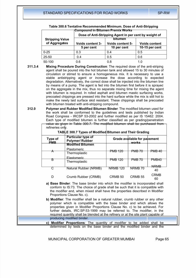
8/19/2019 MCGM Road Spec Volume -II
http://slidepdf.com/reader/full/mcgm-road-spec-volume-ii 69/176
STANDARD SPECIFICATIONS FOR ROAD WORKS SP-RW
MUNICIPAL CORPORATION OF GREATER MUMBAI Page 65
Table 300.6 Tentative Recommended Minimum. Dose of Anti-StrippingCompound in Bitumen Premix Works
Stripping Value
of Aggregates
Dose of Anti-Stripping Agent in per cent by weight ofbitumen
Voids content 3-5 per cent
Voids content 5-10 per cent
Voids content10-15 per cent
0-25 0.3 0.4 0.5
25-50 0.4 0.5 0.6
50-100 0.6 0.8 1.0
311.3.4 Mixing Procedure During Construction: The required dose of the anti-stripingagent shall be poured into the hot bitumen tank and allowed 15 to 30 minutes ofcirculation or stirred to ensure a homogeneous mix. It is necessary to use astable antistripping agent or increase the dose according to expecteddegradation. Alternatively, the correct dose shall be injected into the bitumen lineby means of a pump. The agent is fed into the bitumen first before it is sprayed
on the aggregate in the mix, thus no separate mixing time for mixing the agentwith bitumen is required. In rolled asphalt and bitumen mastic surfacing works,precoated chippings are pressed into the hard surface while the mix is still hot tomake the newly laid surface skid resistant. These chippings shall be precoatedwith bitumen treated with anti-stripping compound.
312.0 Polymer and Rubber Modified Bitumen Binder : The modified bitumen used forthe work shall be conformed to the guidelines and tests published by IndianRoad Congress - IRCSP 53-2002 and further modified as per IS 15462: 2004.Each type of modified bitumen is further classified as per grading/penetrationvalue as given in Table 300.7. The modified bitumen shall be purchased fromrefineries only.
TABLE 300.7 Types of Modified Bitumen and Their Grading
Type ofPMB
Particular type ofPolymer/ RubberModified Bitumen
Grade available for pavementworks
APlastomericThermoplastic
PMB 120 PMB 70 PMB 40
BElastomericThermoplastic
PMB 120 PMB 70 PMB40
C Natural Rubber (NRMB) NRMB 120 NRMB 70NRMB
40
D Crumb Rubber (CRMB) CRMB 50 CRMB 55 CRMB60
a) Base Binder : The base binder into which the modifier is incorporated shallconform to IS:73. The choice of grade shall be such that it is compatible withthe modifier and, when mixed shall have the properties described in ModifierProportions Clause No. c).
b) Modifier : The modifier shall be a natural rubber, crumb rubber or any otherpolymer which is compatible with the base binder and which allows theproperties given in Modifier Proportions Clause No. c) to be achieved. Forfurther details, IRC:SP:53-1999 may be referred to. The modifier, in therequired quantity shall be blended at the refinery or at the site plant capable ofproducing modified binder.
c) Modifier Proportions: The quantity of modifier to be added shall bedetermined by tests on the base binder and the modified binder and the
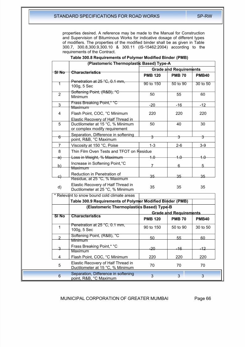
8/19/2019 MCGM Road Spec Volume -II
http://slidepdf.com/reader/full/mcgm-road-spec-volume-ii 70/176
STANDARD SPECIFICATIONS FOR ROAD WORKS SP-RW
MUNICIPAL CORPORATION OF GREATER MUMBAI Page 66
properties desired. A reference may be made to the Manual for Constructionand Supervision of Bituminous Works for indicative dosage of different typesof modifiers. The properties of the modified binder shall be as given in Table300.7, 300.8,300.9,300.10 & 300.11 (IS-15462:2004) according to therequirements of the Contract.
Table 300.8 Requirements of Polymer Modified Binder (PMB)
(Plastomeric Thermoplastic Based) Type-A
Sl No CharacteristicsGrade and Requirements
PMB 120 PMB 70 PMB40
1Penetration at 25 °C, 0.1 mm,100g, 5 Sec
90 to 150 50 to 90 30 to 50
2Softening Point, (R&B), °CMinimum
50 55 60
3Frass Breaking Point,* °CMaximum
-20 -16 -12
4 Flash Point, COC, °C Minimum 220 220 220
5Elastic Recovery of Half Thread inDuctilometer at 15 °C, % Minimumor complex modify requirement
50 40 30
6Separation, Difference in softeningpoint, R&B, °C Maximum
3 3 3
7 Viscosity at 150 °C, Poise 1-3 2-6 3-9
8 Thin Film Oven Tests and TFOT on Residue
a) Loss in Weight, % Maximum 1.0 1.0 1.0
b) Increase in Softening Point,°CMaximum 7 6 5
c)Reduction in Penetration ofResidue, at 25 °C, % Maximum
35 35 35
d)Elastic Recovery of Half Thread inDuctilometer at 25 °C, % Minimum
35 35 35
* Relevant to snow bound cold climate areas
Table 300.9 Requirements of Polymer Modified Binder (PMB)
(Elastomeric Thermoplastics Based) Type-B
Sl No CharacteristicsGrade and Requirements
PMB 120 PMB 70 PMB40
1Penetration at 25 °C, 0.1 mm,100g, 5 Sec
90 to 150 50 to 90 30 to 50
2Softening Point, (R&B), °CMinimum
50 55 60
3Frass Breaking Point,* °CMaximum
-20 -16 -12
4 Flash Point, COC, °C Minimum 220 220 220
5Elastic Recovery of Half Thread inDuctilometer at 15 °C, % Minimum
70 70 70
6 Separation, Difference in softeningpoint, R&B, °C Maximum 3 3 3

8/19/2019 MCGM Road Spec Volume -II
http://slidepdf.com/reader/full/mcgm-road-spec-volume-ii 71/176
STANDARD SPECIFICATIONS FOR ROAD WORKS SP-RW
MUNICIPAL CORPORATION OF GREATER MUMBAI Page 67
Sl No CharacteristicsGrade and Requirements
PMB 120 PMB 70 PMB40
7 Viscosity at 150 °C, Poise 1-3 2-6 3-9
8 Thin Film Oven Tests and TFOT on Residue
a) Loss in Weight, % Maximum 1.0 1.0 1.0
b)Increase in Softening Point,°CMaximum
7 6 5
c)Reduction in Penetration ofResidue, at 25 °C, % Maximum
35 35 35
d)Elastic Recovery of Half Thread inDuctilometer at 25 °C, % Minimum
50 50 50
* Relevant to snow bound cold climate area
Table 300.10 Requirements of Natural Rubber Binder (NRMB)
(Natural Rubber Based) Type-C
Sl No CharacteristicsGrade and Requirements
NRMB 120 NRMB 70 NRMB 40
1Penetration at 25 °C, 0.1 mm,100g, 5 Sec
90 to 150 50 to 90 30 to 50
2Softening Point, (R&B), °CMinimum
45 50 55
3Frass Breaking Point,* °CMaximum
-20 -16 -12
4 Flash Point, COC, °C Minimum 220 220 220
5 Elastic Recovery of Half Thread inDuctilometer at 15 °C, % Minimum 50 40 30
6Separation, Difference in softeningpoint, R&B, °C Maximum
4 4 4
7 Viscosity at 150 °C, Poise 1-3 2-6 3-9
8 Thin Film Oven Tests and TFOT on Residue
a) Loss in Weight, % Maximum 1.0 1.0 1.0
b)Increase in Softening Point,°CMaximum
7 6 5
c)Reduction in Penetration of
Residue, at 25 °C, % Maximum
40 40 40
d)Elastic Recovery of Half Thread inDuctilometer at 25 °C, % Minimum
35 25 20
* Relevant to Snow Bound Cold Climate Areas
Table 300.11 Requirements of Crumb Rubber Modified Binder
(Crumb and Modified Crumb Rubber Based) Type-D
Sl No CharacteristicsGrade and Requirements
CRMB 50 CRMB 55 CRMB 60
1Penetration at 25 °C, 0.1 mm,
100g, 5 Sec<70 <60 <50
2 Softening Point, (R&B), °C 50 55 60
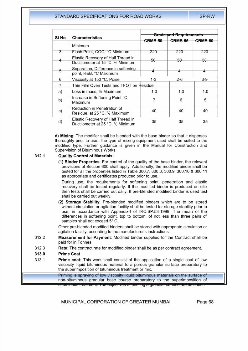
8/19/2019 MCGM Road Spec Volume -II
http://slidepdf.com/reader/full/mcgm-road-spec-volume-ii 72/176
STANDARD SPECIFICATIONS FOR ROAD WORKS SP-RW
MUNICIPAL CORPORATION OF GREATER MUMBAI Page 68
Sl No CharacteristicsGrade and Requirements
CRMB 50 CRMB 55 CRMB 60
Minimum
3 Flash Point, COC, °C Minimum 220 220 220
4Elastic Recovery of Half Thread inDuctilometer at 15 °C, % Minimum
50 50 50
5Separation, Difference in softeningpoint, R&B, °C Maximum
4 4 4
6 Viscosity at 150 °C, Poise 1-3 2-6 3-9
7 Thin Film Oven Tests and TFOT on Residue
a) Loss in mass, % Maximum 1.0 1.0 1.0
b)Increase in Softening Point,°CMaximum
7 6 5
c)Reduction in Penetration ofResidue, at 25 °C, % Maximum 40 40 40
d)Elastic Recovery of Half Thread inDuctilometer at 25 °C, % Minimum
35 35 35
d) Mixing: The modifier shall be blended with the base binder so that it dispersesthoroughly prior to use. The type of mixing equipment used shall be suited to themodified type. Further guidance is given in the Manual for Construction andSupervision of Bituminous Works.
312.1 Quality Control of Materials:
(1) Binder Properties: For control of the quality of the base binder, the relevant
provisions of Section 600 shall apply. Additionally, the modified binder shall betested for all the properties listed in Table 300.7, 300.8, 300.9, 300.10 & 300.11as appropriate and certificates produced prior to use.
During use, the requirements for softening point, penetration and elasticrecovery shall be tested regularly. If the modified binder is produced on sitethen tests shall be carried out daily. If pre-blended modified binder is used testshall be carried out weekly.
(2) Storage Stability: Pre-blended modified binders which are to be storedwithout circulation or agitation facility shall be tested for storage stability prior touse, in accordance with Appendix-I of IRC:SP:53-1999. The mean of thedifferences in softening point, top to bottom, of not less than three pairs of
samples shall not exceed 5° C.Other pre-blended modified binders shall be stored with appropriate circulation oragitation facility, according to the manufacturer's instructions.
312.2 Measurement for Payment: Modified binder supplied for the Contract shall bepaid for in Tonnes.
312.3 Rate: The contract rate for modified binder shall be as per contract agreement.
313.0 Prime Coat
313.1 Prime coat: This work shall consist of the application of a single coat of lowviscosity liquid bituminous material to a porous granular surface preparatory tothe superimposition of bituminous treatment or mix.
Priming is spraying of low viscosity liquid bituminous materials on the surface of
non-bituminous granular base course preparatory to the superimposition ofbituminous treatment. The objectives of priming a granular surface are as under:

8/19/2019 MCGM Road Spec Volume -II
http://slidepdf.com/reader/full/mcgm-road-spec-volume-ii 73/176

8/19/2019 MCGM Road Spec Volume -II
http://slidepdf.com/reader/full/mcgm-road-spec-volume-ii 74/176

8/19/2019 MCGM Road Spec Volume -II
http://slidepdf.com/reader/full/mcgm-road-spec-volume-ii 75/176
STANDARD SPECIFICATIONS FOR ROAD WORKS SP-RW
MUNICIPAL CORPORATION OF GREATER MUMBAI Page 71
After the base to be primed has been prepared as in section 313.2.2, the primershall be uniformly applied using the appropriate equipment at application ratespecified in Table 300.10.1 or 300.10.2 as applicable. The spraying should becarried out using pressure sprayer or distributor. The method of application ofprimer will also depend on the type of equipment to be used, size of nozzles,pressure at spray bar and speed of the forward movement of vehicle. A trialsection shall be laid to check the efficacy of equipment as well as penetrationdepth (10 mm) of the priming material.
313.4: Temperature of Application of Primer :
No heating of SS-1 bitumen emulsion is permitted at site. In case of cutbackbitumen, temperature of application of primer should be high enough to permitthe primer to be sprayed effectively through the jets of the spray bar and to coverthe base course surface effectively. The temperature of product at the time ofapplication should be more than 10°C.
313.5: Air Curing and Opening of Traffic:
The primed surface shall be allowed to cure for at least 24 hours or any otherhigher period, as is found to be necessary to allow all the moisture or volatiles toevaporate before any subsequent bituminous surface treatment or mix is laid.Excessive and unabsorbed primer if any shall be blotted with a light applicationof sand using the minimum quantity possible. A primed surface shall not beopened for traffic other than that necessary construction vehicles to lay the nextbituminous course.
Arrangement for traffic
During the period of construction, appropriate arrangement for traffic diversionshall be made as specified in IRC:SP:55 to prevent any possible damage ofprimed surface.
313.6: Quality Control:
The Quality Control shall be undertaken as under:
Test Frequency or Tests
Quality of Binder One set of test for a tanker or lot of 10tonne as per IS:217 for cutbackbitumen and IS:8887 for bitumenemulsion (Appendix-1 )
Binder Temperature for application Regular Intervals
Rate of spread of binder 1 test per 1000 m2 and not less than twotests per day
(Appendix 2)
313.3 Measurements for Payment: prime coat shall be measured in terms of surfacearea of application in square metres.
313.4 Rate: The contract unit rate for prime coat shall be payment in full for carryingout the required operations including for all components listed in Clause318.11 (i)to (v) and as applicable to the work specified in these Specifications. The rateshall cover the provision of tack coat at 0.2 Kg per Square Metre, with theprovision that the variance in actual quantity of bitumen used will be assessedand the payment adjusted accordingly.
314.0 Tack Coat
This work shall consist of the application of a single coat of low viscosity liquidbituminous material to an existing bituminous, cement concrete or primedgranular road surface to ensure a bond between the surface being paved and theoverlaying course. The track coat material is not expected to penetrate into

8/19/2019 MCGM Road Spec Volume -II
http://slidepdf.com/reader/full/mcgm-road-spec-volume-ii 76/176
STANDARD SPECIFICATIONS FOR ROAD WORKS SP-RW
MUNICIPAL CORPORATION OF GREATER MUMBAI Page 72
pavement and for this reason, the application should be very light to provideadequate bond between two layers. The preparatory to the superimposition of abituminous mix, when specified in the Contract or instructed by the Engineer.
314.1 Binder : The binder used for tack coat shall be bitumen emulsion complying with
IS: 8887:2004 of a type and grade as specified in the Contract or as directed bythe Engineer. The use of cutback bitumen as per IS: 217 shall be restricted onlyfor sites at sub-zero temperatures or for emergency applications as directed bythe Engineer.
The binder used for tack coat shall be either Cationic Bitumen Emulsion (RS- l)confonning to IS: 8887/ASTM D 2397 or suitable low viscosity Paving bitumen ofVG 10 grade conforming to IS:73. The use of cutback bitumen RC-70 (in coldclimate) as per IS:217 shall be restricted only for sites where atmospherictemperature at the time of application reaches below 0oC or for emergencyapplications.
314.2 Weather and Seasonal Limitations: Bituminous material shall not be applied to awet surface or during a dust storm or when the weather is foggy, rainy or windy
or when the temperature in the shade is less than 10oC, where the tack coat'consists of emulsion, the surface shall be slightly damp, but not wet. Where thetack coat is of cutback bitumen, the surface shall be dry.
314.3 Construction :
314.3.1 Equipment: The tack coat distributor shall be a self-propelled or towed bitumenpressure sprayer, equipped for spraying the material uniformly at a specifiedrate. Hand spraying of small areas, inaccessible to the distributor, or in narrowstrips, shall be sprayed with a pressure hand sprayer, or as directed by theEngineer.
314.3.2 Preparation of Base: The surface on which the tack coat is to be applied shallbe clean and free from dust, dirt and any extraneous material, and be otherwise
prepared in accordance with the requirements of Clauses 318.8 and 600 asappropriate. Immediately before the application of tack coat, the surface shall beswept clean with a mechanical broom, and high pressure air jet, or any othermeans as directed by the Engineer.
The method of application of tack coat will also depend on the type of equipmentto be used, size of nozzles, pressure at spray bar and speed of the forwardmovement of vehicle. A spraying trial shall demonstrate that the equipment andmethod to be used is capable of providing a uniform spray, within specifiedtolerance limit. The quantity of tack coat shall be checked periodically using traycoating test as described in Appendix 2. The dilution of RS-I bitumen emulsion isnot permitted
314.3.3 Application of Tack Coat: The application of tack coat shall be at the ratespecified in the Contract, and shall be applied uniformly. If rate of application ofTack Coat is not specified in the contract then it shall be at the rate specified inTable 300.11A. The normal range of spraying temperature for a bituminousemulsion shall be 20°C to 70°C and for a cutback, 50°C to 80°C if RC-70/MC-70is used. Where a geo-synthetic is proposed for use, the provisions of Clause 260shall apply. The method of application of the tack coat will depend on the type ofequipment to be used, size of nozzles, pressure at the spray bar, and speed offorward movement. The Contractor shall demonstrate at a spraying trial, that theequipment and method to be used is capable of producing a uniform spray,within the tolerances specified.

8/19/2019 MCGM Road Spec Volume -II
http://slidepdf.com/reader/full/mcgm-road-spec-volume-ii 77/176
STANDARD SPECIFICATIONS FOR ROAD WORKS SP-RW
MUNICIPAL CORPORATION OF GREATER MUMBAI Page 73
Table 300.11A Rate of Application of Tack Coat
Sl. No Type of Surface
Rate of Sparay(Emulsion)
(Kg / m2)
Rate of Sparay(Bitumen VG -
10)
(Kg / m2
)(i) Bituminous Surfaces 0.20 to 0.30 0.30 to 0.40
(ii)Granular surfaces treated
with primer0.25 to 0.30 0.35 to 0.45
(iii) Cement concrete pavement 0.30 to 0 15 0.40 to 0.50
Where the material to receive an overlay is a freshly laid bituminous layer thathas not been subjected to traffic or contaminated by dust, a tack coat is notmandatory where the overlay is completed within two days.
314.3.4 Curing of Tack Coat: The tack coat shall be left to cure until all the volatileshave evaporated before any subsequent construction is started, which isindicated by change in colour from brown to black. No plant or vehicles shall beallowed on the tack coat other than those essential for the construction.
314.3.5 Temperature of Application of Track Coat:
No heating of RS-1 Bitumen Emulsion is permitted at site. Paving Bitumen ifused shall be heated to its appropriate application temperature in bitumen boilerto achieve desired viscosity of less than 2 poise. The normal range of sprayingtemperature for a bituminous emulsion shall be 20°C to 70°C and for a cutback.500C to 800C if RC- 70/MC·70 is used. In case of cutback bitumen, temperatureof application of primer should be high enough to permit the tack coat to besprz.yed effectively through the jets of the spray bar and to cover the basecourse surface uniformly. In case of the use of paving grade bitumen, viscosity atthe time of application shall be less than 2 poise so that spraying is uniformly.
314.3.6 Quality Control:
Tests to be conducted on bitumen, cutback bitumen and bitumen emulsion aregiven in Appendix- 1. Manufacture shall provide test certificate for each batchindicating date of manufacture, batch number and signature of quality control incharge. The details of tray test for measurement (If quantities are given in Appendix -2.The Quality Control sball be undertaken as under: -
Test Frequency of Tests
Quality of Binder test per batch ofproduct by the manufacturer
One set of test for a tanker or lot of 10tonne as per IS:73 for bitumen andIS:8887 for bitumen emulsion (Appendix-1)
Binder Temperature for application Regular Intervals
Rate of spread of binder 1 test per 1000 m2 and not less than twotests per day (Appendix- 2)
314.4 Quality Control of Work: For control of the quality of materials supplied and theworks carried out, the relevant provisions of Section 600 shall apply.
314.5 Arrangements for Traffic: During the period of construction, arrangements fortraffic shall be made in accordance with the provisions of Clause 30.
314.6 Measurements for Payment: Tack coat shall be measured in terms of surfacearea of application in square metres.
314.7 Rate: The contract unit rate for tack coat shall be payment in full for carrying out
the required operations including for all components listed in Clause 318.11 (i) to(v) and as applicable to the work specified in these Specifications. The rate shall
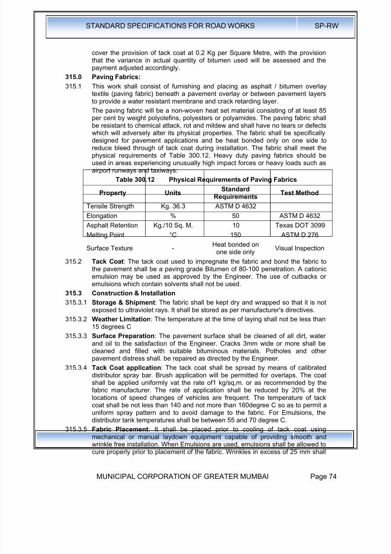
8/19/2019 MCGM Road Spec Volume -II
http://slidepdf.com/reader/full/mcgm-road-spec-volume-ii 78/176
STANDARD SPECIFICATIONS FOR ROAD WORKS SP-RW
MUNICIPAL CORPORATION OF GREATER MUMBAI Page 74
cover the provision of tack coat at 0.2 Kg per Square Metre, with the provisionthat the variance in actual quantity of bitumen used will be assessed and thepayment adjusted accordingly.
315.0 Paving Fabrics:
315.1 This work shall consist of furnishing and placing as asphalt / bitumen overlaytextile (paving fabric) beneath a pavement overlay or between pavement layersto provide a water resistant membrane and crack retarding layer.
The paving fabric will be a non-woven heat set material consisting of at least 85per cent by weight polyolefins, polyesters or polyamides. The paving fabric shallbe resistant to chemical attack, rot and mildew and shall have no tears or defectswhich will adversely alter its physical properties. The fabric shall be specificallydesigned for pavement applications and be heat bonded only on one side toreduce bleed through of tack coat during installation. The fabric shall meet thephysical requirements of Table 300.12. Heavy duty paving fabrics should beused in areas experiencing unusually high impact forces or heavy loads such asairport runways and taxiways:
Table 300.12 Physical Requirements of Paving Fabrics
Property UnitsStandard
RequirementsTest Method
Tensile Strength Kg. 36.3 ASTM D 4632
Elongation % 50 ASTM D 4632
Asphalt Retention Kg./10 Sq. M. 10 Texas DOT 3099
Melting Point °C 150 ASTM D 276
Surface Texture -Heat bonded on
one side onlyVisual Inspection
315.2 Tack Coat: The tack coat used to impregnate the fabric and bond the fabric tothe pavement shall be a paving grade Bitumen of 80-100 penetration. A cationicemulsion may be used as approved by the Engineer. The use of cutbacks oremulsions which contain solvents shall not be used.
315.3 Construction & Installation
315.3.1 Storage & Shipment: The fabric shall be kept dry and wrapped so that it is notexposed to ultraviolet rays. It shall be stored as per manufacturer's directives.
315.3.2 Weather Limitation: The temperature at the time of laying shall not be less than15 degrees C
315.3.3 Surface Preparation: The pavement surface shall be cleaned of all dirt, waterand oil to the satisfaction of the Engineer. Cracks 3mm wide or more shall be
cleaned and filled with suitable bituminous materials. Potholes and otherpavement distress shall. be repaired as directed by the Engineer.
315.3.4 Tack Coat application: The tack coat shall be spread by means of calibrateddistributor spray bar. Brush application will be permitted for overlaps. The coatshall be applied uniformly vat the rate of1 kg/sq,m. or as recommended by thefabric manufacturer. The rate of application shall be reduced by 20% at thelocations of speed changes of vehicles are frequent. The temperature of tackcoat shall be not less than 140 and not more than 160degree C so as to permit auniform spray pattern and to avoid damage to the fabric. For Emulsions, thedistributor tank temperatures shall be between 55 and 70 degree C.
315.3.5 Fabric Placement: It shall be placed prior to cooling of tack coat using
mechanical or manual laydown equipment capable of providing smooth andwrinkle free installation. When Emulsions are used, emulsions shall be allowed tocure properly prior to placement of the fabric. Wrinkles in excess of 25 mm shall
8/19/2019 MCGM Road Spec Volume -II
http://slidepdf.com/reader/full/mcgm-road-spec-volume-ii 79/176
STANDARD SPECIFICATIONS FOR ROAD WORKS SP-RW
MUNICIPAL CORPORATION OF GREATER MUMBAI Page 75
be slit and laid flat. Brooming and / or pneumatic rolling will be required tomaximise paving fabric contact with pavement. Care in movement of paver andother vehicles shall be taken to avoid damage to the fabric. Overlap shall beshingle lapped in the direction of paving.
315.3.6 Overlay placement: Minimum thickness of overlay over the fabric shall be40mm. The overlay shall closely follow fabric placement. Excess tack coat beremoved by broadcasting hot mix or and on the fabric.
315.4 Measurement for Payment: Each application of paving fabric shall be measuredas finished work, for the area specified, in square metres.
316.5 Rate : The contract unit rate for the paving fabric shall be payment in full forcarrying out the required operations including full compensation for allcomponents listed in Clause 318.11, (i) to (xi).
316.0 Stress Absorbing Membrane & Stress Absorbing Membrane inter layer:
316.1 Crack Prevention Courses: This clause covers the provision of Stress Absorbing Membrane (SAM) and Stress Absorbing Membrane Interlayer (SAMI)
as measures to inhibit the propagation of cracks. A SAM is an elastomericbitumen rubber membrane, which is laid over a cracked road surface, togetherwith a covering of aggregate chips, in order to extend the life of the pavementbefore major treatment is carried out. SAM can be laid as a single coat or adouble coat. A SAMI is a layer which is applied to a cracked pavement surfacebut which is followed (within 12 months) by the application of an overlay course. A SAMI may be a material similar to that used for a SAM .. It may alternativelyconsist of a bitumen impregnated geo-textile.
316.2 Materials:
316.2.1 Binder: Binder shall be a modified binder complying with the requirements ofClause 311.4, according to the requirements of the Contract, except that pavinggrade bitumen of 90 penetration complying with the requirements of IS: 73 shallbe used in the case of bitumen impregnated geo-textile.
316.2.2 Aggregate: The requirements of Clause 318.1.1 apply except that the PolishedStone Value requirements do not apply in the case of a SAMI. Where required bythe contract, aggregate shall be pre-coated using either of the techniquespermitted by Clause 510.2.5 of MoRTH.
316.2.3 Rates of spread of binder and aggregate: The rates of spread of binder andaggregate shall be according to one of the size alternatives in Table 300.12, asrequired by the Contract.
Geo-textile: The use of geo-textile as prescribed for SI. No.7 in Table 300.12shall conform to the requirements of Clause 135.0.
316.2.4 Construction Operations:316.2.4.1 Preparation of base: The base on which the SAM, SAMI or bitumen
impregnated geo-textile is to be laid shall be prepared, in accordance withClause 300 and as directed by the Engineer. The surface shall be thoroughlycleaned wither by using a mechanical brush or any other equipment I methodapproved by the Engineer. Dust removed in the process shall be blown off withcompressed air.
316.2.4.2 Application of Binder : The equipment and general procedures shall all be inaccordance with the Manual for Construction and Supervision of BituminousWorks. The application temperature for modified binder shall be 160-170°C.Binder for bitumen impregnated geo-textile shall be applied according to Clause313. The surface on which the binder is to be applied shall be dry.
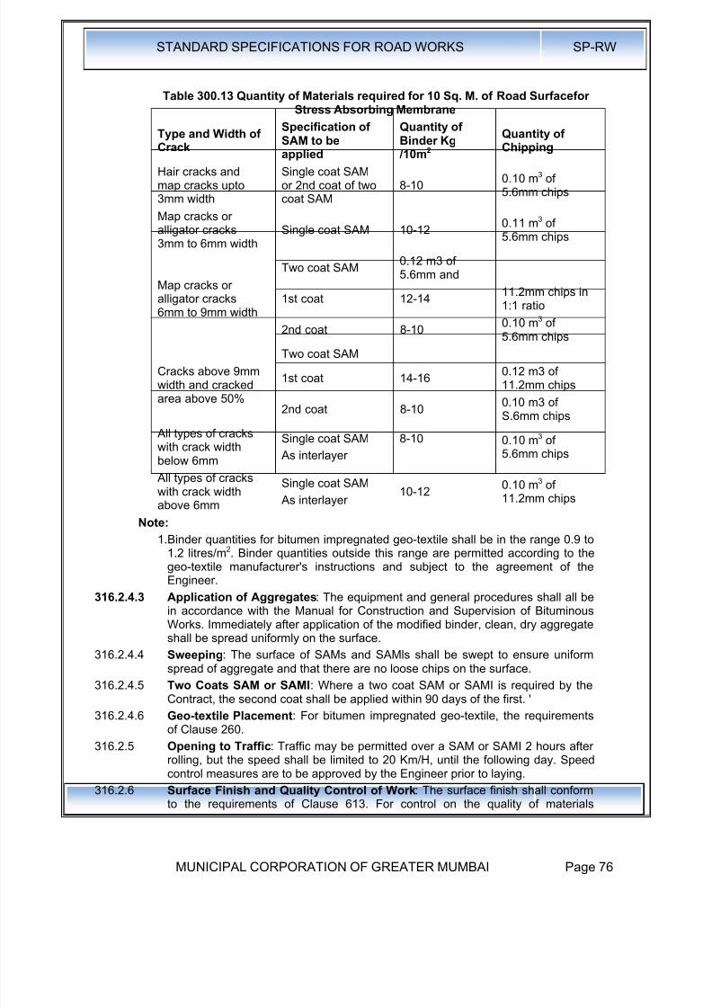
8/19/2019 MCGM Road Spec Volume -II
http://slidepdf.com/reader/full/mcgm-road-spec-volume-ii 80/176
STANDARD SPECIFICATIONS FOR ROAD WORKS SP-RW
MUNICIPAL CORPORATION OF GREATER MUMBAI Page 76
Table 300.13 Quantity of Materials required for 10 Sq. M. of Road SurfaceforStress Absorbing Membrane
Type and Width ofCrack
Specification ofSAM to be
applied
Quantity ofBinder Kg
/10m
2
Quantity ofChipping
Hair cracks andmap cracks upto3mm width
Single coat SAMor 2nd coat of twocoat SAM
8-100.10 m3 of5.6mm chips
Map cracks oralligator cracks3mm to 6mm width
Single coat SAM 10-120.11 m3 of5.6mm chips
Map cracks oralligator cracks6mm to 9mm width
Two coat SAM0.12 m3 of5.6mm and
1st coat 12-1411.2mm chips in1:1 ratio
2nd coat 8-10 0.10 m3 of5.6mm chips
Cracks above 9mmwidth and crackedarea above 50%
Two coat SAM
1st coat 14-160.12 m3 of11.2mm chips
2nd coat 8-100.10 m3 ofS.6mm chips
All types of crackswith crack widthbelow 6mm
Single coat SAM
As interlayer
8-10 0.10 m3 of5.6mm chips
All types of crackswith crack widthabove 6mm
Single coat SAM
As interlayer10-12
0.10 m3 of11.2mm chips
Note:
1.Binder quantities for bitumen impregnated geo-textile shall be in the range 0.9 to1.2 litres/m2. Binder quantities outside this range are permitted according to thegeo-textile manufacturer's instructions and subject to the agreement of theEngineer.
316.2.4.3 Application of Aggregates: The equipment and general procedures shall all bein accordance with the Manual for Construction and Supervision of BituminousWorks. Immediately after application of the modified binder, clean, dry aggregate
shall be spread uniformly on the surface.316.2.4.4 Sweeping: The surface of SAMs and SAMls shall be swept to ensure uniform
spread of aggregate and that there are no loose chips on the surface.
316.2.4.5 Two Coats SAM or SAMI: Where a two coat SAM or SAMI is required by theContract, the second coat shall be applied within 90 days of the first. '
316.2.4.6 Geo-textile Placement: For bitumen impregnated geo-textile, the requirementsof Clause 260.
316.2.5 Opening to Traffic: Traffic may be permitted over a SAM or SAMI 2 hours afterrolling, but the speed shall be limited to 20 Km/H, until the following day. Speedcontrol measures are to be approved by the Engineer prior to laying.
316.2.6 Surface Finish and Quality Control of Work: The surface finish shall conform
to the requirements of Clause 613. For control on the quality of materials

8/19/2019 MCGM Road Spec Volume -II
http://slidepdf.com/reader/full/mcgm-road-spec-volume-ii 81/176
STANDARD SPECIFICATIONS FOR ROAD WORKS SP-RW
MUNICIPAL CORPORATION OF GREATER MUMBAI Page 77
supplied and the works carried out, the relevant provisions of Section 600 shallapply.
316.2.7 Arrangement for Traffic: During the period of construction, arrangements fortraffic shall be made.
316.2.8 Measurement for Payment: Each application of SAM, SAMI or bitumenimpregnated geo-textile shall be measured as finished work, for the areaspecified, in square metres.
316.2.9 Rate: The contract unit rate for SAM, SAMI or bitumen impregnated geo-textileshall be payment in full for carrying out the required operations including fullcompensation for all components listed in Clause 318.11, (i) to (xi).
317.0 Bituminous Cold Mixes
317.1 Binder : The binder shall be a bituminous emulsion as specified in IS- 8887:2004and in clause 305 or 306. Alternatively, a cutback bitumen as specified in ASHTO M 82 (ASTM 02027) OR ASTM 0 2026, namely MC 70, 250, 800 & 3000and SC 250. 800 and 3000 may be used, or, if approved by the Engineer, an
equivalent material which conforms with IS:8887 and IS:217. A general guide for the use of these binders is given in Table 300.14 and in theManual for Construction and Supervision of Bituminous Works. However, thefinal selection shall be made only after laboratory evaluation with the aggregatesto be used. The binder with the highest residual viscosity at ambienttemperatures that can reasonably be handled by the mixing and layingequipment proposed shall be used.
Table 300.14 Uses of Bitumen in Cold Mix
Type ofConstruction
Emulsified Bitumen Cutback Bitumen
Anionic CationicMedium Curing
(MC)
SlowCuring
(SC)
Cold-LaidPlant Mix
Pavement BaseandSurface
M S - 2 , H F M S - 2
M S - 2 h , H F M S - 2 h
H F M S - 2 s
S S - 1
S S - 1 h
C M S - 2
C M S - 2 h
C S S – 1
C S S – 1
h
7 0
2 5 0
8 0 0
3 0 0 0
2 5 0
8 0 0
3 0 0 0
Open-Graded Aggregate
X X X X
Well-Graded Aggregate
X X X X X X X X X X X
Patching,Immediate Use
X X X X X X X
Patching,Stockpile
X X X X
317.2 Aggregates: The aggregates shall comply with the requirements of Clause318.1.1 and 318.1.2. If the aggregates are not properly coated with anionic
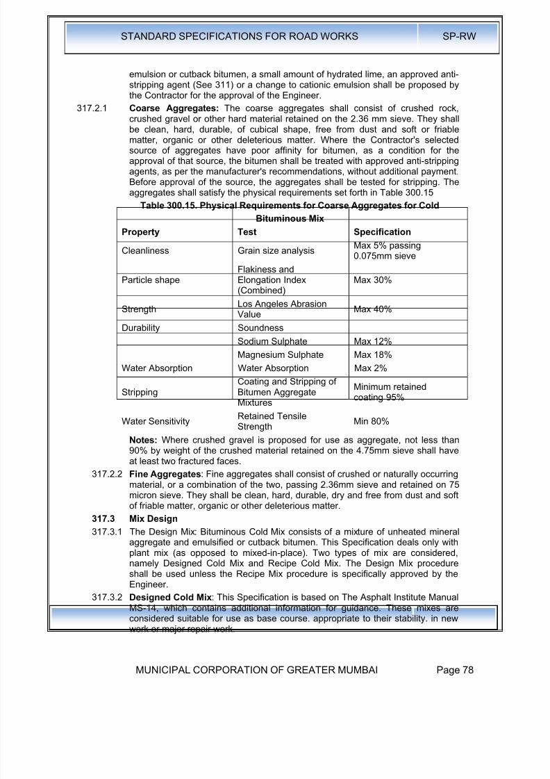
8/19/2019 MCGM Road Spec Volume -II
http://slidepdf.com/reader/full/mcgm-road-spec-volume-ii 82/176
STANDARD SPECIFICATIONS FOR ROAD WORKS SP-RW
MUNICIPAL CORPORATION OF GREATER MUMBAI Page 78
emulsion or cutback bitumen, a small amount of hydrated lime, an approved anti-stripping agent (See 311) or a change to cationic emulsion shall be proposed bythe Contractor for the approval of the Engineer.
317.2.1 Coarse Aggregates: The coarse aggregates shall consist of crushed rock,
crushed gravel or other hard material retained on the 2.36 mm sieve. They shallbe clean, hard, durable, of cubical shape, free from dust and soft or friablematter, organic or other deleterious matter. Where the Contractor's selectedsource of aggregates have poor affinity for bitumen, as a condition for theapproval of that source, the bitumen shall be treated with approved anti-strippingagents, as per the manufacturer's recommendations, without additional payment.Before approval of the source, the aggregates shall be tested for stripping. Theaggregates shall satisfy the physical requirements set forth in Table 300.15
Table 300.15. Physical Requirements for Coarse Aggregates for Cold
Bituminous Mix
Property Test Specification
Cleanliness Grain size analysis Max 5% passing0.075mm sieve
Particle shapeFlakiness andElongation Index(Combined)
Max 30%
StrengthLos Angeles AbrasionValue
Max 40%
Durability Soundness
Sodium Sulphate Max 12%
Magnesium Sulphate Max 18%
Water Absorption Water Absorption Max 2%
StrippingCoating and Stripping ofBitumen AggregateMixtures
Minimum retainedcoating 95%
Water SensitivityRetained TensileStrength
Min 80%
Notes: Where crushed gravel is proposed for use as aggregate, not less than90% by weight of the crushed material retained on the 4.75mm sieve shall haveat least two fractured faces.
317.2.2 Fine Aggregates: Fine aggregates shall consist of crushed or naturally occurringmaterial, or a combination of the two, passing 2.36mm sieve and retained on 75
micron sieve. They shall be clean, hard, durable, dry and free from dust and softof friable matter, organic or other deleterious matter.
317.3 Mix Design
317.3.1 The Design Mix: Bituminous Cold Mix consists of a mixture of unheated mineralaggregate and emulsified or cutback bitumen. This Specification deals only withplant mix (as opposed to mixed-in-place). Two types of mix are considered,namely Designed Cold Mix and Recipe Cold Mix. The Design Mix procedureshall be used unless the Recipe Mix procedure is specifically approved by theEngineer.
317.3.2 Designed Cold Mix: This Specification is based on The Asphalt Institute ManualMS-14, which contains additional information for guidance. These mixes are
considered suitable for use as base course. appropriate to their stability. in newwork or major repair work.
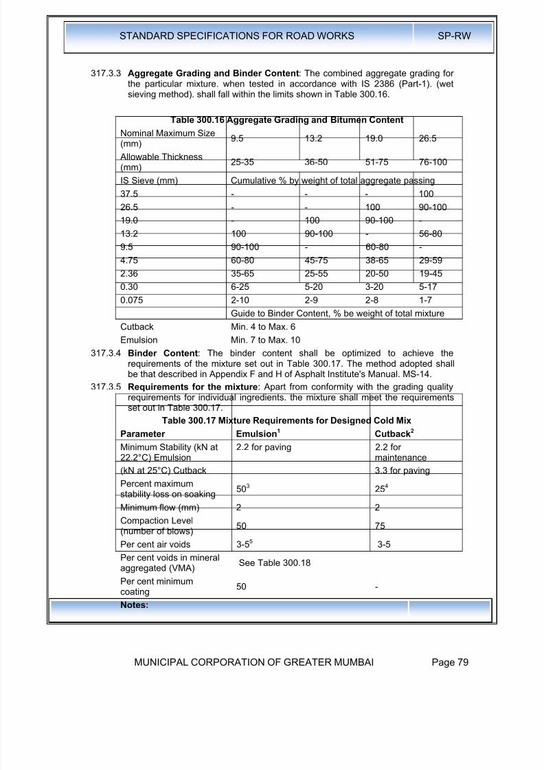
8/19/2019 MCGM Road Spec Volume -II
http://slidepdf.com/reader/full/mcgm-road-spec-volume-ii 83/176
STANDARD SPECIFICATIONS FOR ROAD WORKS SP-RW
MUNICIPAL CORPORATION OF GREATER MUMBAI Page 79
317.3.3 Aggregate Grading and Binder Content: The combined aggregate grading forthe particular mixture. when tested in accordance with IS 2386 (Part-1). (wetsieving method). shall fall within the limits shown in Table 300.16.
Table 300.16 Aggregate Grading and Bitumen ContentNominal Maximum Size(mm)
9.5 13.2 19.0 26.5
Allowable Thickness(mm)
25-35 36-50 51-75 76-100
IS Sieve (mm) Cumulative % by weight of total aggregate passing
37.5 - - - 100
26.5 - - 100 90-100
19.0 - 100 90-100 -
13.2 100 90-100 - 56-80
9.5 90-100 - 60-80 -
4.75 60-80 45-75 38-65 29-59
2.36 35-65 25-55 20-50 19-45
0.30 6-25 5-20 3-20 5-17
0.075 2-10 2-9 2-8 1-7
Guide to Binder Content, % be weight of total mixture
Cutback Min. 4 to Max. 6
Emulsion Min. 7 to Max. 10
317.3.4 Binder Content: The binder content shall be optimized to achieve the
requirements of the mixture set out in Table 300.17. The method adopted shallbe that described in Appendix F and H of Asphalt Institute's Manual. MS-14.
317.3.5 Requirements for the mixture: Apart from conformity with the grading qualityrequirements for individual ingredients. the mixture shall meet the requirementsset out in Table 300.17.
Table 300.17 Mixture Requirements for Designed Cold Mix
Parameter Emulsion1 Cutback2
Minimum Stability (kN at22.2°C) Emulsion
(kN at 25°C) Cutback
2.2 for paving 2.2 formaintenance
3.3 for paving
Percent maximumstability loss on soaking 503 254
Minimum flow (mm) 2 2
Compaction Level(number of blows)
50 75
Per cent air voids 3-55 3-5
Per cent voids in mineralaggregated (VMA)
See Table 300.18
Per cent minimumcoating
50 -
Notes:
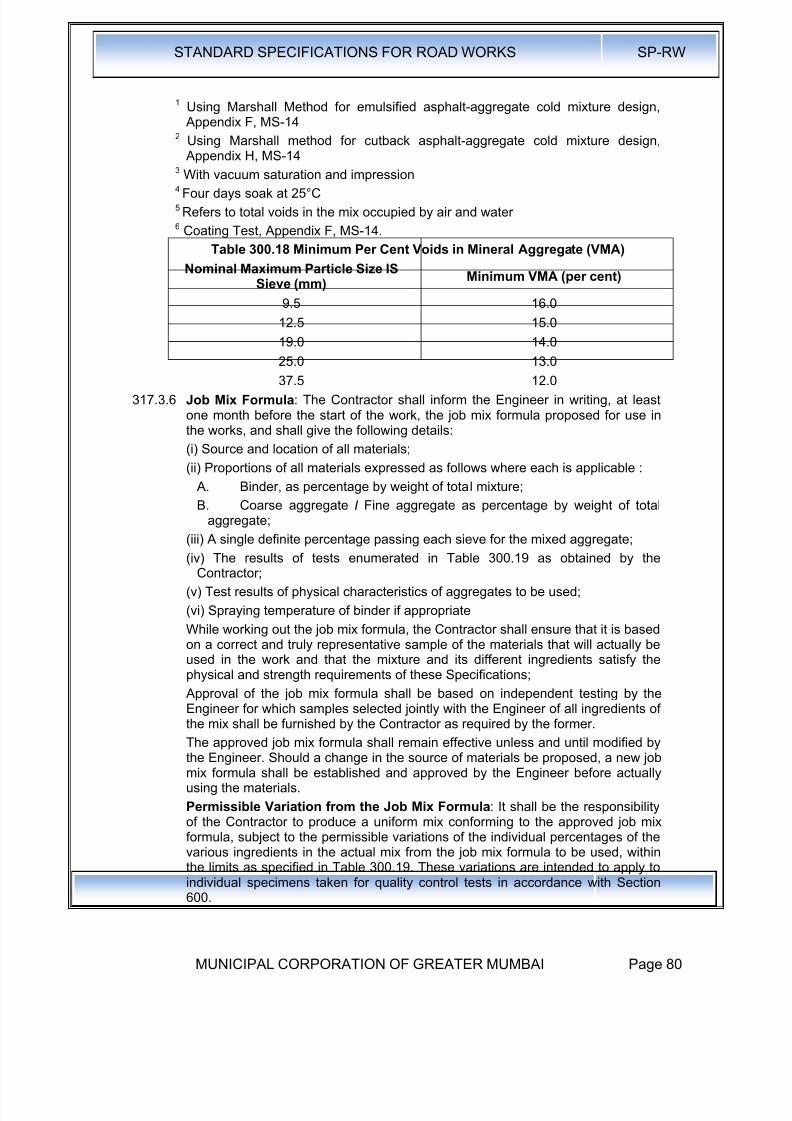
8/19/2019 MCGM Road Spec Volume -II
http://slidepdf.com/reader/full/mcgm-road-spec-volume-ii 84/176
STANDARD SPECIFICATIONS FOR ROAD WORKS SP-RW
MUNICIPAL CORPORATION OF GREATER MUMBAI Page 80
1 Using Marshall Method for emulsified asphalt-aggregate cold mixture design, Appendix F, MS-14
2 Using Marshall method for cutback asphalt-aggregate cold mixture design, Appendix H, MS-14
3
With vacuum saturation and impression4 Four days soak at 25°C5 Refers to total voids in the mix occupied by air and water6 Coating Test, Appendix F, MS-14.
Table 300.18 Minimum Per Cent Voids in Mineral Aggregate (VMA)
Nominal Maximum Particle Size ISSieve (mm)
Minimum VMA (per cent)
9.5 16.0
12.5 15.0
19.0 14.0
25.0 13.0
37.5 12.0
317.3.6 Job Mix Formula: The Contractor shall inform the Engineer in writing, at leastone month before the start of the work, the job mix formula proposed for use inthe works, and shall give the following details:
(i) Source and location of all materials;
(ii) Proportions of all materials expressed as follows where each is applicable :
A. Binder, as percentage by weight of total mixture;
B. Coarse aggregate I Fine aggregate as percentage by weight of totalaggregate;
(iii) A single definite percentage passing each sieve for the mixed aggregate;
(iv) The results of tests enumerated in Table 300.19 as obtained by theContractor;
(v) Test results of physical characteristics of aggregates to be used;
(vi) Spraying temperature of binder if appropriate
While working out the job mix formula, the Contractor shall ensure that it is basedon a correct and truly representative sample of the materials that will actually beused in the work and that the mixture and its different ingredients satisfy thephysical and strength requirements of these Specifications;
Approval of the job mix formula shall be based on independent testing by the
Engineer for which samples selected jointly with the Engineer of all ingredients ofthe mix shall be furnished by the Contractor as required by the former.
The approved job mix formula shall remain effective unless and until modified bythe Engineer. Should a change in the source of materials be proposed, a new jobmix formula shall be established and approved by the Engineer before actuallyusing the materials.
Permissible Variation from the Job Mix Formula: It shall be the responsibilityof the Contractor to produce a uniform mix conforming to the approved job mixformula, subject to the permissible variations of the individual percentages of thevarious ingredients in the actual mix from the job mix formula to be used, withinthe limits as specified in Table 300.19. These variations are intended to apply to
individual specimens taken for quality control tests in accordance with Section600.

8/19/2019 MCGM Road Spec Volume -II
http://slidepdf.com/reader/full/mcgm-road-spec-volume-ii 85/176
STANDARD SPECIFICATIONS FOR ROAD WORKS SP-RW
MUNICIPAL CORPORATION OF GREATER MUMBAI Page 81
317.3.7 Weather and Seasonal Limitations: Construction with cold mix must not beundertaken when ambient temperatures below 10°C are expected, during rain, instanding water, or generally when poor weather is predicted. Bitumen emulsionsand cutbacks depend on the evaporation of water and I or· solvent for thedevelopment of their curing and adhesion characteristics. Cold weather, rain andhigh humidity slow down the rate of curing. Extra manipulation may be requiredto remove volatiles in cool and humid conditions. Wind increases the rate ofevaporation.
Table 300.19/20 Permissible Variations from the Job Mix Formula
Description Permissible Variation
Base / Binder Course Wearing Course
Aggregate passing 19mm sieveor larger
±8% ±7%
Aggregate passing 13.2mm,9.5mm
±7% ±6%
Aggregate passing 4.75mm ±6%±5%
Aggregate passing 2.36mm,1.18mm,0.6mm
±5% ±4%
Aggregate . passing 0.3mm,0.15mm
±4% ±3%
Aggregate passing O.075mm ±2% ± 1.5%
Binder Content ±0.3% ±0.3%
317.3.8 Preparation of the base: The base on which cold mix is to be laid shall beprepared, shaped and levelled to the required profile in accordance with Clauses
318.10 and 600as appropriate, and a prime coat, where specified, shall beapplied in accordance with Clause 313 or as directed by the Engineer.
317.3.9 Tack Coat: A tack coat in accordance with Clause 314 shall be applied over thebase on which the cold mix is to be laid where specified in the Contract.
317.3.10 Preparation and transportation of the mixture : Mixing can be carried outusing one of the following types of mixer, which is provided with equipment forspraying the binder at a controlled rate and, if necessary, for heating the binderto a temperature at which it can be applied uniformly to the aggregate:
a) rotary drum type concrete mixer,
b) single or twin shaft concrete or macadam mixer,
c) batch or continuous type mixer without dryer on screens other than a
scalping screen.
A sufficient number of haul trucks with smooth, clean beds should be available toensure continuous operation of the mixing plant. The type of truck used fortransporting the mixture from the mixer to the road site must be suited to theContractor's nominated laying procedure methodology.
317.3.11 Spreading: Designed cold mix shall be placed only when the specified densitycan be obtained. The mixture shall not be placed on any wet surface or whenweather conditions will otherwise prevent its proper handling or finishing.
If spreading by motor grader, the grader must have a blade that is straight andsharp and long enough to ensure finishing to close, straight, transversetolerances and all joints and linkages must be in good condition. The grader must
be heavy enough to hold the blade firmly and uniformly on the surface whilespreading the mixture.

8/19/2019 MCGM Road Spec Volume -II
http://slidepdf.com/reader/full/mcgm-road-spec-volume-ii 86/176
STANDARD SPECIFICATIONS FOR ROAD WORKS SP-RW
MUNICIPAL CORPORATION OF GREATER MUMBAI Page 82
If climatic conditions and aggregate grading permit evaporation of moisture ofvolatiles without aeration by manipulation, a conventional self-propelled asphaltpaver shall be used to place designed cold mix.
Other methods of spreading may be used as approved by the Engineer.
317.3.12 Compaction: Initial compaction of the laid material shall be carried out using apneumatic-tyred roller of a weight appropriate to the layer thickness to becompacted with single layer thickness being 25-100mm and all compaction beingin accordance with Clause 318.8. Smooth tyres shall be used. Final rolling andsmoothing of the surface should be completed using steel wheel rollers. TheContractor shall demonstrate at laying trials that his: proposed laying andcompaction methods can achieve a satisfactory result.
317.3.13 Opening to Traffic: Traffic shall not be allowed to run on new work until all thewater or volatiles in the mixture have evaporated, as determined by theEngineer. The rate of evaporation will be influenced by the temperature, humidityand wind conditions.
317.3.14 Surface Finish and Quality Control of Work: The surface finish of constructionshall conform to the requirements of Clause 900. For control of the quality ofsupplied materials and the works carried out, the relevant provisions of Section600shall apply.
317.3.15 Arrangements for Traffic: During the period of construction, arrangements fortraffic shall be made in accordance with the provisions of Clause 30.
317.3.16 Measurement for Payment: Designed Cold Mix shall be measured as finishedwork, for the area covered, in cubic metres, by weight in metric tones, or bysquare metres at a specified thickness as specified in the Contract.
317.3.17 Rate: The contract unit rate for Designed Cold Mix shall be payment in full forcarrying out the required operations including full compensation for allcomponents listed in Clause 318.11 (i) to (xi). The rate shall cover the provisionof the specified grade of cutback in the mix at 5 percent of the weight of the totalmix or emulsion at 8 per cent of the weight of the total mix, with the provision thatthe variation of quantity of binder will be assessed on the basis of the amountagreed by the Engineer and the payment adjusted as per the rate for cutback oremulsion .quoted in the Bill of Quantities.
318.0 Bituminous Hot Mixes
318.1 Aggregates:
318.1.1 Coarse Aggregates: Coarse Aggregates shall consists of crushed rock retainedon 2.36mm sieve. They shall be cleaned, hard, durable, of cubical shape, freefrom dust, and soft or friable matter, organic or other deleterious matter. Wherethe selected sources of aggregate have poor affinity for bitumen, the bitumenshall be treated with approved anti-stripping agents as per the manufacturer'srecommendations. The aggregate shall satisfy the physical requirements setforth in the individual relevant clause for the material in question.
318.1.2 Fine Aggregates: Fine aggregates shall consist of crushed or naturally occurringmaterial or a combination of the two passing 4.75mm sieve and retained on 75Micron sieve. They shall be cleaned, hard, durable, dry, and free from dust, andsoft or friable matter, organic or other deleterious matter. The amount ofrounded, natural sand in the total fine aggregate shall be 10 percent if the BM isused within 100 mm from the road surface and to 50 percent if the BM is usedmore than 100 mm below the road surface. (clause 3.3 of IRC: 27-2009)
318.1.3 Source of Materials·: The source of all materials to be used on the: project must
be tested to the satisfaction of and be expressly approved by the Engineer. TheEngineer may from time to time withdraw approval of a specific source, or attach
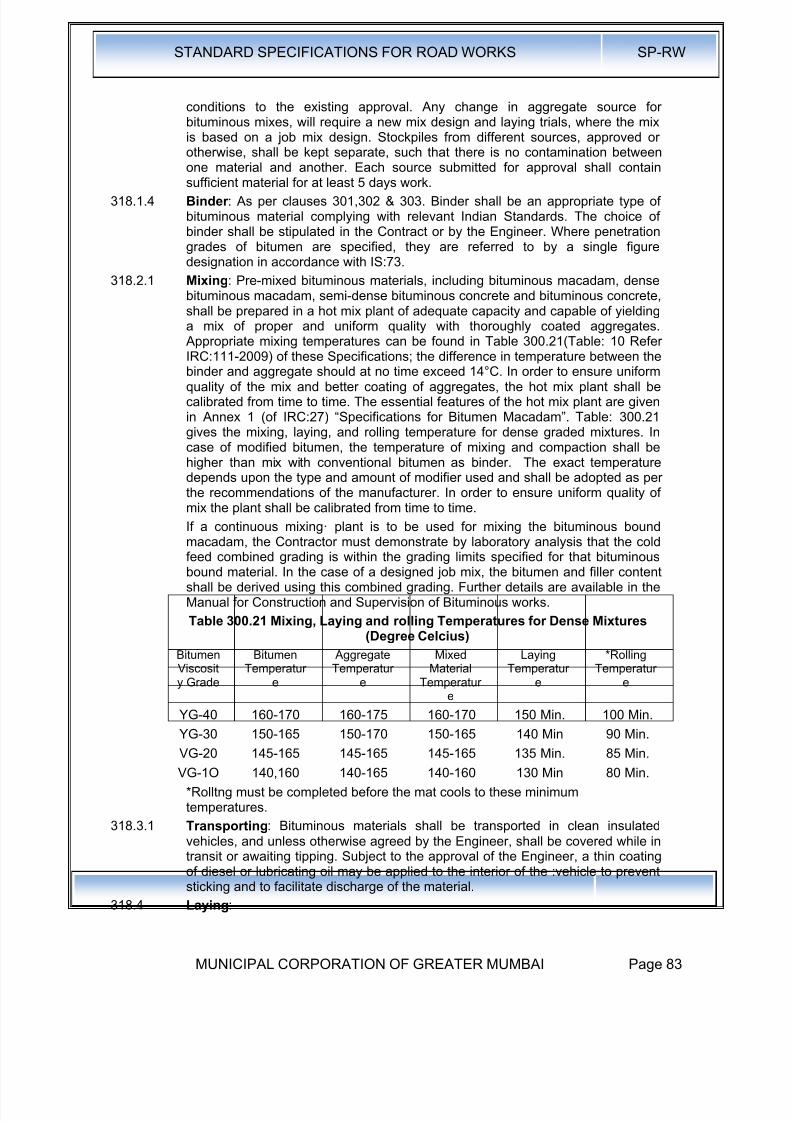
8/19/2019 MCGM Road Spec Volume -II
http://slidepdf.com/reader/full/mcgm-road-spec-volume-ii 87/176

8/19/2019 MCGM Road Spec Volume -II
http://slidepdf.com/reader/full/mcgm-road-spec-volume-ii 88/176
STANDARD SPECIFICATIONS FOR ROAD WORKS SP-RW
MUNICIPAL CORPORATION OF GREATER MUMBAI Page 84
318.4.1 Weather and Seasonal Limitations: Laying shall be suspended while free-standing water is present on the surface to be covered, or during rain, fog anddust storms. After rain, the bituminous surface, prime or tack coat, shall be blownoff with a high pressure air jet to remove excess moisture, or the surface left todry before laying shall start. Laying of bituminous mixtures shall not be carriedout when the air temperature at the surface on which it is to be laid is below 10°Cfor mix with conventional bitumen as binder and is less than 15°C for mix withmodified bitumen as binder or when the wind speed at any temperature exceeds40 Km/H at 2m height unless specifically approved by the Engineer.
318.5 Cleaning of Surface : The surface on which the bituminous work is to be laidshall be cleaned of all loose and extraneous matter by means of a mechanicalbroom or any other approved equipment I method as specified in the contract.The use of a high pressure air jet from a compressor to remove dust or loosematter shall be available full time on the site, unless otherwise specified in theContract.
318.6 Spreading: Except in areas where a mechanical paver cannot access,
bituminous materials shall be spread, levelled and tamped by an approved self-propelled hydrostatic paver finisher preferably with sensor. As soon as possibleafter arrival at site, the materials shall be supplied continuously to the paver andlaid without delay.
The rate of delivery of material to the paver shall be regulated to enable thepaver to operate continuously. The travel rate of the paver, and its method ofoperations, shall be adjusted to ensure an even and uniform flow of bituminousmaterial across the screed, free from dragging, tearing and segregation of thematerial. In areas with restricted space ( such as confined space, footways,irregular shape and varying thickness, approaches to expansion joints, etc)where a mechanical paver cannot be used, the material shall be spread, raked
and levelled with suitable hand tools by experienced staff, and compacted to thesatisfaction of the Engineer.
The minimum thickness of material laid in each paver pass shall be inaccordance with the minimum values given in the relevant part of theseSpecifications. When laying binder course or wearing course approaching anexpansion joint of ,a structure, machine laying shall stop 300mm short of the joint. The remainder of the pavement up to the joint, and the corresponding areabeyond it, shall be laid by hand, and the joint or joint cavity shall be kept clear ofsurfacing material.
Bituminous material, with a temperature greater than 145°C, shall not be laid ordeposited on bridge deck waterproofing systems, unless precautions againstheat damage have been approved by the Engineer.
Hand placing of pre-mixed bituminous materials shall only be permitted in thefollowing circumstances:
i) For laying regulating courses of irregular shape and varying thickness,
ii) In confined spaces where it is impracticable for a paver to operate
iii) For footways
iv) At the approaches to expansion joints at bridges, viaducts or otherstructures
Manual spreading of pre-mixed wearing course material or the addition of suchmaterial by hand-spreading to the paved area, for adjustment of level, shall onlybe permitted in the following circumstances:
i. At the edges of the layers of material and at gullies and manholesii. At the approaches to expansion joints at bridges, viaducts or other structures

8/19/2019 MCGM Road Spec Volume -II
http://slidepdf.com/reader/full/mcgm-road-spec-volume-ii 89/176
STANDARD SPECIFICATIONS FOR ROAD WORKS SP-RW
MUNICIPAL CORPORATION OF GREATER MUMBAI Page 85
iii. As directed by the Engineer
318.7 Cleanliness and Overlaying: Bituminous material shall be kept clean anduncontaminated. The only traffic permitted to run on bituminous material to beoverlaid shall be that engaged in laying and compacting the next course or,
where a binder course is to be sealed or surface dressed, that engaged on suchsurface treatment.
Binder course material shall not remain uncovered by either the wearing courseor· surface treatment, whichever is specified in the Contract, for more than threeconsecutive days after being laid. The Engineer may extend this period, by theminimum amount of time necessary, because of weather conditions or for anyother reason. If the surface of the base is subjected to traffic, or not coveredwithin three days, a tack coat shall be applied, as directed by the Engineer.
318.8 Compaction: Bituminous materials shall be laid and compacted in layers whichenable the specified thickness, surface level, regularity requirements andcompaction to be achieved.
Compaction of bituminous materials shall commence as soon as possible afterlaying. Compaction-shall be substantially completed before the temperature fallsbelow the minimum rolling temperatures stated in the relevant part of theseSpecifications. Rolling of the longitudinal joints shall be done immediately behindthe paving operation. After this, rolling shall commence at the edges andprogress towards the centre longitudinally except that on super elevated andunidirectional cambered portions, it shall progress from the lower to the upperedge parallel to the centre line of the pavement. Rolling shall continue until allroller marks- have been removed from the surface and minimum specified fielddensity is achieved . All deficiencies in the surface after laying shall be madegood by the attendants behind the paver, before initial rolling is commenced. Theinitial or breakdown rolling shall be done with 8-10 tonnes dead weight smooth-
wheeled rollers. The intermediate rolling shall be done with 8- 10 tonnes deadweight or vibratory roller or with a pneumatic tyred roller of 12 to 15 tonnesweight having nine wheels, with a tyre pressure of at least 5.6 Kg / Sq. Cm. Thefinish rolling shall be done with 6 to 8 tonnes smooth wheeled tandemrollers.Where compaction is to be determined by density of cores therequirements to prove the performance of rollers shall apply in order todemonstrate that the specified density can be achieved. In such cases theContractor shall nominate the plant, and the method by which he intends toachieve the specified level of compaction and finish at temperatures above theminimum specified rolling temperature. Laying trials shall then demonstrate theacceptability of the plant and method used.
Bituminous materials shall be rolled in a longitudinal direction, with the roller as
close as possible to the paver. The roller shall first compact material adjacent to joints and then work from the lower to the upper side of the layer, overlapping onsuccessive passes by at least one-third of the width of the rear roll or, in the caseof a pneumatic-tyred roller, at least the nominal width of 300mm.
In portions with super-elevated and unidirectional camber, after the edge hasbeen rolled, the roller shall progress from the lower to the upper edge.
Rollers should move at a speed of not more than 5 km per hour. The roller shallnot be permitted to stand on pavement which has not been fully compacted, andnecessary precautions shall be taken to prevent dropping oil, grease, petrol, orother foreign matter on the pavement either when the rollers are operating orstanding. The wheels of rollers shall be kept moist with water, and the spray
system provided with the machine shall be in good working order, to prevent themixture from adhering to the wheels. Only sufficient moisture to prevent adhesion
8/19/2019 MCGM Road Spec Volume -II
http://slidepdf.com/reader/full/mcgm-road-spec-volume-ii 90/176
STANDARD SPECIFICATIONS FOR ROAD WORKS SP-RW
MUNICIPAL CORPORATION OF GREATER MUMBAI Page 86
between the wheels of rollers and the mixture should be used. Surplus watershall not be allowed to stand on the partially compacted pavement.
The density of the finished paving layer shall be determined by taking 150mmdiameter cores. The density of finished paving layer shall not be less than 92% of
the average (sample size N = 2 ) theoretical maximum specific gravity of theloose mix (Gmm) obtained on that day in accordance with ASTM D2041. See Annex 3 for the outline of ASTM D2041
318.9 Joints : Where longitudinal joints are made in pre-mixed bituminous materials,the materials shall be fully compacted and the joint made flush in one of thefollowing ways; only method (iii) shall be used for . transverse joints:
a) All joints shall be cut vertical to the full thickness of the previously laid mix. All loosened material shall be discarded and the vertical face be coated withany viscosity grade bitumen, or cold applied emulsified bitumen. Whilespreading the material along the joint the material spread shall overlap 25 mm10 50 mill on the previously laid mix beyond the vertical face of the joint. Thethickness of the loose overlap material should be approximately a qum1er
more than the final compacted thickness. The overlapped mix should bedragged back 10 the hot lane so that the roller can press the small excess intothe hot side of the joint to obtain a high joint density.
b) By using two or more pavers in echelon, where this is practicable and insufficient proximity for adjacent width to be fully compacted by continuousrolling.
In multilayer construction the longitudinal joint in one layer shall offset the joint inthe underneath layer by about 150 mm.
For transverse joints method a) above can apply Transverse joints in thesuccessive and adjoining layers should have a minimum offset of 2 m.
i. By heating the joints with an approved joint heater when the adjacent widthis being laid, but without cutting back or coating with binder. The heatershall raise the temperature of the full depth of material, to within thespecified> range of minimum rolling temperature and maximumtemperature at any stage for the material, for a width not less than 75mm.The Contractor shall have equipment available, for use in the event of aheater breakdown, to form joints by method (iii);
ii. By using two or more pavers operating in echelon, where this ispracticable, and in sufficient proximity for adjacent widths to be fullycompacted by continuous rolling;
iii. By cutting back the exposed joint, for a distance equal to the specifiedlayer thickness, to a vertical face, discarding all loosened material and
coating the vertical face completely with 80/100 penetration grade hotbitumen, or cold-applied bitumen, or polymer modified adhesive bitumentape with a minimum thickness of 2mm, before the adjacent width is laid.
All joints shall be offset at least 300mm from parallel joints in the layer beneath oras directed, and in a layout approved by the Engineer. Joints in the wearingcourse shall coincide with either the lane edge or the lane marking, whichever isappropriate. Longitudinal joints shall not be situated in wheel track zones.Transverse joints in the successive and adjoining layers should have a minimumoffset of 2m. (IRC:111-2009 clause 5.7.3)
All joints shall be cut vertical to the full thickness of the previously laid mix. Allloosened material shall be discarded and the vertical face be coated with any
viscosity grade bitumen, or cold applied emulsified bitumen. While spreading thematerial along the joint the material spread shall overlap 25 mm to 50 mm on the
8/19/2019 MCGM Road Spec Volume -II
http://slidepdf.com/reader/full/mcgm-road-spec-volume-ii 91/176
STANDARD SPECIFICATIONS FOR ROAD WORKS SP-RW
MUNICIPAL CORPORATION OF GREATER MUMBAI Page 87
previously laid mix beyond the vertical face of the joint. The thickness of theloose overlap material should be approximately a quarter more than the finalcompacted thickness. The overlapped mix should be dragged back to the hotlane so that the roller can press the small excess into the hot side of the joint toobtain a high joint density. (IRC:111-2009 clause 5.7.3)
318.10 Preparation of Surface:
This work shall consist of preparing an existing granular or blacktopped surfacebituminous course. The work shall be performed on such widths and lengths asshown on the drawings or as instructed by the" Engineer. The existing surfaceshall be firm and clean, and treated with Prime and Tack Coat as shown on thedrawings as otherwise stated in the Contract.
318.10.1 Preparing existing granular surface: Where the existing surface is granular, allloose materials shall be removed, and the surface lightly watered where theprofile corrective course to be provided as a separate layer is also granular.Where the profile corrective course of bituminous material is to be laid over theexisting granular surface, the latter shall, after removal of all loose material, be
primed in accordance with Clause 313.
The surface finish of all granular layers on which bituminous works are to beplaced, shall, unless otherwise specifically instructed by the Engineer, be freefrom dust. All such layers must be capable of being swept, after the removal ofany non-integral loose material, by means of a mechanical broom, withoutshedding significant quantities of material and dust removed by air jet, washing,or other means approved by the Engineer.
After cleaning the surface shall be correct to line and level, within the tolerancesspecified for base course.
318.10.1.1 Scarifying existing bituminous surface: Where specified or shown on thedrawings, the existing bituminous layer in the specified width shall be removed
with care and without causing undue disturbance to the underlying layer, by asuitable method approved by the Engineer. After removal, all loose anddisintegrated material, the underlying layers which might have been disturbedshould be suitably reworked and compacted to line and level. Aftersupplementing the base material as necessary with suitable fresh stone, thecompacted finished surface shall be primed in accordance with Clause 313.Reusable materials shall be stacked as directed by the Engineer within 1000m oftheir origin.
318.11 Rates for Premixed Bituminous Material : The contract unit rate for premixedbituminous material shall be payment in full or carrying out the requiredoperations including full compensation for, but not necessarily limited to:
i. Making arrangements for traffic to Clause 30 except for initial treatment toverge, shoulders and construction of diversions,
ii. Preparation of the surface to receive the material,
iii. Providing all materials to be incorporated in the work includingarrangement for stock yards, all royalties, fees, rents where necessary andall leads and lifts,
iv. Mixing, transporting, laying and compacting the mix, as specified,
v. All labour, tools, equipment, plant including installation of hot mix plant,power supply units and all machinery, incidental to complete the work tothese Specifications,
vi. Carrying out the work in part widths of the road where directed,
vii. Carrying out all tests for control of quality and,

8/19/2019 MCGM Road Spec Volume -II
http://slidepdf.com/reader/full/mcgm-road-spec-volume-ii 92/176

8/19/2019 MCGM Road Spec Volume -II
http://slidepdf.com/reader/full/mcgm-road-spec-volume-ii 93/176
STANDARD SPECIFICATIONS FOR ROAD WORKS SP-RW
MUNICIPAL CORPORATION OF GREATER MUMBAI Page 89
350.0 Bituminous Base
351.0 Bituminous Macadam:
Bituminous Macadam (BM) shall consist of mineral aggregate and appropriate
binder, mixed in a hot mix plant and laid with a mechanical paver. It is an opengraded mixture suitable for base course. It is laid in a single course or in multiplelayers on a previously prepared base. ( caluse 2.2 of IRC:27-2009) This workshall consist of construction in a single course having 50mm to 100mm thicknessor in multiple courses of compacted crushed aggregates premixed with abituminous binder on a previously prepared base to the requirements of theseSpecifications.
Since the bituminous macadam is an open graded mixture, there is a potentialthat it may trap water or moisture vapour within the pavement system. Therefore,adjacent layer should have proper drainage quantity to prevent moisture-induceddamage to the B.M. (caluse 2.3 of IRC:27-2009)
351.1 Coarse Aggregates: As per 318.1.1. The aggregates shall satisfy the physicalrequirements set forth in Table 300.22.(caluse 3.3 Table:3 of IRC:27-2009)
The coarse aggregate shall consist of crushed rock, crushed gravel or other hardmaterial retained on 2.36 mm sieve. It shall be clean, hard, durable and cubicalshape. free from dust and soft organic and other deleterious substances. Theaggregate shall satisfy the physical requirements specified in Table 300.22
Where crushed gravel is proposed for use as aggregate, not less than 90% byweight of the crushed material retained on 4.75 mill sieve shall have at least twofractured faces resulting from crushing operation.
Table 300.22 Physical Requirements for Coarse Aggregates
Property Test Requirement Test method
Cleanliness Grain size analysisMax 5% passing0.075mm
IS:2386 -part I
Particle shapeFlakiness andElongation Index(Combined)
Max 40% IS:2386 -part I
Strength*Los Angeles AbrasionValue
Max 40% IS2386 -part IV
Aggregate Impactvalue
Max .30 % IS:2386 -part IV
Durability
Soundness (Sodium
or Magnesium),Sodium Sulphate
5 cycles
Max 12%IS:2386 -part V
Magnesium Sulphate Max 18% IS:2386 -part V
Water Absorption
Water Absorption Max 2% IS:2386 -part III
StrippingCoating and Strippingof Bitumen Aggregate
MinimumRetained Coating95 %
IS:6241
WaterSensitivity
Retained Tensilestrength**
Min 80% AASHTO 283
Notes• Elongation test to be done on non-flaky particles.

8/19/2019 MCGM Road Spec Volume -II
http://slidepdf.com/reader/full/mcgm-road-spec-volume-ii 94/176
STANDARD SPECIFICATIONS FOR ROAD WORKS SP-RW
MUNICIPAL CORPORATION OF GREATER MUMBAI Page 90
** If the minimum retained coating in the stripping test is less than 95%
Change Bitumen Content for Grade 1 and Grade 2 to 3.3 % and 3.4 %respectively in Table 300. 23
Table 300.23 Composition of Bituminous Macadam
Mix Designation Grading 1 Grading 2 Grading 3Nominal Aggregate Size 40mm 19mm 40mm
Layer Thickness 80-100mm 50-75mm 80-100 mm
lS Sieve (mm) Cumulative % by weight of total aggregatepassing
45 100 100
37.5 90-100 50-75
26.5 75-100 100 --
19 - 90-100 --
13.2 35-61 56-88 30-504.75 13-22 16-36 10-17
2.36 4-19 4-19 3-15
0.3 2-10 2-10 2-5
0.075 0-8 0-8 0-3
Bitumen Content, % byweight of Total Mixture
3.2 (Min) 3.3 (Min) 2.9 (Min)
Bitumen Grade 35 to 90 35 to 90 35-65
* Nominal maximum aggregate size is the largest specified sieve size uponwhich any of the aggregate material is retained.
** Corresponds to specific gravity of the Aggregate being 2.7. In case aggregatehave specific gravity more than 2.7, bitumen content can be reducedproportionately. Further, for regions where highest daily mean air temperatureis 300C or lower and lowest-daily mean air temperature is – 100C: or lower thebitumen content may be increased by as much as 0.5 percent. Tolerance of0.3%; by weight of mix is allowed to individual specimen taken up for qualitycontrol
351.2 Fine Aggregates: As per Clause 318.1.2.
351.3 Bitumen: The bitumen shall be paving bitumen of Penetration Grade complyingwith Indian Standard Specifications for "Paving Bitumen" IS:73 and of thepenetration indicated in Table 300.23.
351.4 Preparation of the base: The base on which bituminous macadam is to be laidshall be prepared, shaped and compacted to the required profile in accordancewith Clauses 318.10 and 600 as appropriate, and a prime coat, shall be appliedin accordance with Clause 313 where specified, or as directed by the Engineer.
351.5 Tack Coat: A tack coat in accordance with Clause 314 shall be applied asrequired by the Contract documents, or as directed by the Engineer.
351.6 Preparation and transportation of the mixture : The provisions of clause318.2.1 and 318.3.1 shall apply.
351.7 Spreading: The provisions of clauses 318.6 shall apply.
351.8 Rolling: Compaction shall be carried out in accordance with the provisions ofClauses 318.8 and 318.9.Rolling shall be continued until the specified density is
achieved, or where no density is specified, until there is no further movementunder the roller. The required frequency of testing is defined in Clause 600.
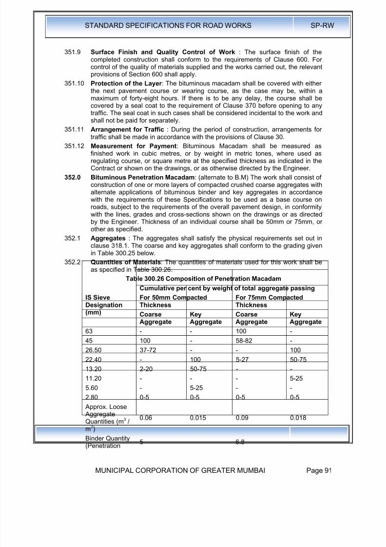
8/19/2019 MCGM Road Spec Volume -II
http://slidepdf.com/reader/full/mcgm-road-spec-volume-ii 95/176
STANDARD SPECIFICATIONS FOR ROAD WORKS SP-RW
MUNICIPAL CORPORATION OF GREATER MUMBAI Page 91
351.9 Surface Finish and Quality Control of Work : The surface finish of thecompleted construction shall conform to the requirements of Clause 600. Forcontrol of the quality of materials supplied and the works carried out, the relevantprovisions of Section 600 shall apply.
351.10 Protection of the Layer : The bituminous macadam shall be covered with eitherthe next pavement course or wearing course, as the case may be, within amaximum of forty-eight hours. If there is to be any delay, the course shall becovered by a seal coat to the requirement of Clause 370 before opening to anytraffic. The seal coat in such cases shall be considered incidental to the work andshall not be paid for separately.
351.11 Arrangement for Traffic : During the period of construction, arrangements fortraffic shall be made in accordance with the provisions of Clause 30.
351.12 Measurement for Payment: Bituminous Macadam shall be measured asfinished work in cubic metres, or by weight in metric tones, where used asregulating course, or square metre at the specified thickness as indicated in theContract or shown on the drawings, or as otherwise directed by the Engineer.
352.0 Bituminous Penetration Macadam: (alternate to B.M) The work shall consist ofconstruction of one or more layers of compacted crushed coarse aggregates withalternate applications of bituminous binder and key aggregates in accordancewith the requirements of these Specifications to be used as a base course onroads, subject to the requirements of the overall pavement design, in conformitywith the lines, grades and cross-sections shown on the drawings or as directedby the Engineer. Thickness of an individual course shall be 50mm or 75mm, orother as specified.
352.1 Aggregates : The aggregates shall satisfy the physical requirements set out inclause 318.1. The coarse and key aggregates shall conform to the grading givenin Table 300.25 below.
352.2 Quantities of Materials: The quantities of materials used for this work shall beas specified in Table 300.26.
Table 300.26 Composition of Penetration Macadam
IS SieveDesignation(mm)
Cumulative per cent by weight of total aggregate passing
For 50mm CompactedThickness
For 75mm CompactedThickness
CoarseAggregate
KeyAggregate
CoarseAggregate
KeyAggregate
63 - - 100 -
45 100 - 58-82 -
26.50 37-72 - - 100
22.40 - 100 5-27 50-75
13.20 2-20 50-75 - -
11.20 - - - 5-25
5.60 - 5-25 - -
2.80 0-5 0-5 0-5 0-5
Approx. Loose AggregateQuantities (m3 /m2)
0.06 0.015 0.09 0.018
Binder Quantity(Penetration
5 6.8

8/19/2019 MCGM Road Spec Volume -II
http://slidepdf.com/reader/full/mcgm-road-spec-volume-ii 96/176
STANDARD SPECIFICATIONS FOR ROAD WORKS SP-RW
MUNICIPAL CORPORATION OF GREATER MUMBAI Page 92
Grade) (Kg/m2)
Note: If cutback bitumen is used, adjust binder quantity such that the residualbitumen is equal to, the values in this table. 352.3
Bitumen : The binder shall be paving bitumen of suitable penetration grade withinthe range of S-35 to S-90 or A-35 to A-90 (35 to 90) as per Indian StandardSpecifications for "Paving Bitumen" IS:73 or approved cutback satisfying therequirements of IS:217 or IS:454. The actual grade of bitumen or cutback to beused shall be as specified or as directed by the Engineer.
352.4 Construction Operations:
352.4.1 Weather and Seasonal Limitations The provisions of Clause 318.4.1 shallapply.
352.4.2 Equipment: A mechanical broom, compressor, self propelled or trailed bitumenheater I distributor, mechanical aggregate spreader and 8 to 10 tonne smoothsteel wheel roller or vibrating roller are required for the preparation of Penetration
Macadam.352.4.3 Preparation of the base : The base on which the Penetration Macadam Course
is to be laid shall be prepared, shaped and compacted to the specified lines,grades and sections to Clauses 610 as appropriate, or as directed by theEngineer. A prime coat, where specified, shall be applied over the base inaccordance with Clause .313 or as directed by the Engineer. A tack coat as perClause 314 shall be applied.
352.4.4 Spreading coarse aggregates : The coarse aggregate shall be dry and cleanand free from dust, and shall be spread uniformly and evenly at the rate specifiedin Table 300.26. It shall be spread by a selfpropelled or tipper tail mountedaggregate spreader capable of spreading aggregate uniformly at the specified
rates over the required widths. The surface of the layer shall be carefullychecked with camber templates to ensure correct line and level and cross fall.The spreading shall be carried out such that the rolling and penetratingoperations can be completed on the same day. Segregated aggregates oraggregates contaminated with foreign material shall be removed and replaced.
352.4.5 Compaction: After the spreading of coarse aggregates, dry rolling shall becarried out with an 8-10 tonne smooth steel wheel roller.
The requirements given in Clause 318.8 shall apply.
After initial dry rolling, the surface shall be checked with a crown template and a3 metre straight-edge. The surface shall not vary more than 10mm from thetemplate or straight-edge. All surface irregularities exceeding the above limitshall be corrected by removing or adding aggregates as required.
The rolling shall continue until the compacted coarse aggregate has a firmsurface true to the cross section shown on the plans and has a texture that willallow free and uniform penetration of the bituminous material.
352.4.6 Application of Bituminous Material : After the coarse aggregate has beenroller and checked, the bituminous binder shall be applied, at the rate given inTable 300.26, in accordance with Clause318, and a temperature directed by theEngineer. At the time of applying the binder, the aggregates shall be surface dryfor the full depth of the layer.
In certain circumstances, depending on the type and size of aggregate used, the,Engineer may direct the' placing of a bed of clean sand or quarry fines, notexceeding 10mm in thickness, on the prepared foundation before placing thecoarse aggregate. The sand or fine material shall be slightly wetted, justsufficient for it to slurry up during the compaction process. Where cut back is

8/19/2019 MCGM Road Spec Volume -II
http://slidepdf.com/reader/full/mcgm-road-spec-volume-ii 97/176
STANDARD SPECIFICATIONS FOR ROAD WORKS SP-RW
MUNICIPAL CORPORATION OF GREATER MUMBAI Page 93
used, if flooding of the binder occurs it should be applied in two operations, or asdirected by the Engineer.
352.4.7 Application of Key Aggregates : Immediately after the first application ofbitumen, the key aggregates, which shall be clean, dry, and free from dust shall
be spread uniformly over the surface by means of an approved mechanicalspreader' or by approved manual methods at the rate specified in Table 300.26.
Where directed by the Engineer, the surface shall be swept and the quantity ofkey aggregate adjusted to ensure uniform application, with all the surface voidsin the coarse aggregate being filled without excess. The entire surface shall thenbe rolled with an 8-10 tonnes smooth steel wheel Toller (or vibrating rolleroperating in non-vibratory mode) in accordance with the procedure specified inClause 352.4.5.
352.4.8 Surface Finish and Quality Control : The surface finish of the completedconstruction shall conform to the requirements of Clauses 610 & 620. For controlof the quality of materials supplied and the works carried out the relevantprovisions of Section 600 shall apply.
352.4.9 Surfacing: The Penetration Macadam shall be provided with a surfacing (binder/ wearing course) within a maximum of forty-eight hours. If there is to be anydelay, the penetration macadam shall be covered by a seal coat to therequirements of Clause 370: before opening to traffic. The seal coat in suchcases shall be considered incidental to the work and shall not be paid forseparately.
352.4.10 Arrangements for Traffic : During the period of construction, arrangements fortraffic shall be made in accordance with the provision of Clause 30.
352.4.11 Measurement for Payment: Penetration Macadam base course shall bemeasured as finished work in square metres.
352.4.12 Rate: The contract unit rate for Penetration Macadam course shall be payment infull for carrying out the required operations including, but not necessarily limitedto, all components listed in Clause 318.11.
353.0
354.0 Dense Graded Bituminous Macadam (DBM) : Dense Graded BituminousMacadam with polymer or rubber modified binder laid over crack preventioncourse as per clause 316.
(Clause 2.2: IRC:111- 2009)
Dense graded bituminous mixes shall consist of mineral aggregate andappropriate bituminous binder. mixed in a hot mix plant and laid with amechanized paver. Dense graded bituminous mixes. such as binder and wearing
courses are usually laid on a previously prepared bituminous layer. Bindercourse is the intermediate layer between bituminous base course and bituminouswearing course, Three different specifications for dense graded bituminousmixes are available for use for highways, Purpose, layer thickness and numberof layers allowed for these specifications are given in Table 300.26.1,Table 300.26.1 Types of Dense Graded Bituminous Mixes, their Use, Number
of Layers and Layer Thickness
Specification PurposeNumber ofLayers
Thickness ofeach Layer
Dense BituminousMacadam (DBM)
Base/ Binder course/Overlay forstrengthening
Single orMultiple
50mm – 100mm
Semi Dense Wearing Course Single 25mm – 40mm
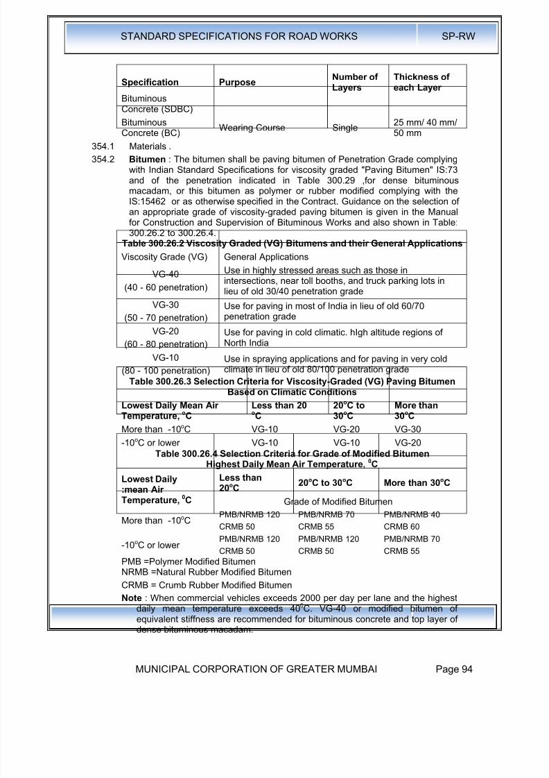
8/19/2019 MCGM Road Spec Volume -II
http://slidepdf.com/reader/full/mcgm-road-spec-volume-ii 98/176
STANDARD SPECIFICATIONS FOR ROAD WORKS SP-RW
MUNICIPAL CORPORATION OF GREATER MUMBAI Page 94
Specification PurposeNumber ofLayers
Thickness ofeach Layer
BituminousConcrete (SDBC)
BituminousConcrete (BC)
Wearing Course Single 25 mm/ 40 mm/50 mm
354.1 Materials .
354.2 Bitumen : The bitumen shall be paving bitumen of Penetration Grade complyingwith Indian Standard Specifications for viscosity graded "Paving Bitumen" IS:73and of the penetration indicated in Table 300.29 ,for dense bituminousmacadam, or this bitumen as polymer or rubber modified complying with theIS:15462 or as otherwise specified in the Contract. Guidance on the selection ofan appropriate grade of viscosity-graded paving bitumen is given in the Manualfor Construction and Supervision of Bituminous Works and also shown in Table:300.26.2 to 300.26.4.
Table 300.26.2 Viscosity Graded (VG) Bitumens and their General ApplicationsViscosity Grade (VG) General Applications
VG-40
(40 - 60 penetration)
Use in highly stressed areas such as those inintersections, near toll booths, and truck parking lots inlieu of old 30/40 penetration grade
VG-30
(50 - 70 penetration)
Use for paving in most of India in lieu of old 60/70penetration grade
VG-20
(60 - 80 penetration)
Use for paving in cold climatic. hIgh altitude regions ofNorth India
VG-10
(80 - 100 penetration)
Use in spraying applications and for paving in very cold
climate in lieu of old 80/100 penetration gradeTable 300.26.3 Selection Criteria for Viscosity-Graded (VG) Paving Bitumen
Based on Climatic Conditions
Lowest Daily Mean AirTemperature, oC
Less than 20oC
20oC to30oC
More than30oC
More than -10oC VG-10 VG-20 VG-30
-10oC or lower VG-10 VG-10 VG-20Table 300.26.4 Selection Criteria for Grade of Modified Bitumen
Highest Daily Mean Air Temperature, 0C
Lowest Daily
:mean AirTemperature, 0C
Less than20oC
20oC to 30oC More than 30oC
Grade of Modified Bitumen
More than -10oCPMB/NRMB 120
CRMB 50
PMB/NRMB 70
CRMB 55
PMB/NRMB 40
CRMB 60
-10oC or lowerPMB/NRMB 120
CRMB 50
PMB/NRMB 120
CRMB 50
PMB/NRMB 70
CRMB 55 PMB =Polymer Modified BitumenNRMB =Natural Rubber Modified Bitumen
CRMB = Crumb Rubber Modified Bitumen
Note : When commercial vehicles exceeds 2000 per day per lane and the highestdaily mean temperature exceeds 400C. VG-40 or modified bitumen of
equivalent stiffness are recommended for bituminous concrete and top layer ofdense bituminous macadam.

8/19/2019 MCGM Road Spec Volume -II
http://slidepdf.com/reader/full/mcgm-road-spec-volume-ii 99/176
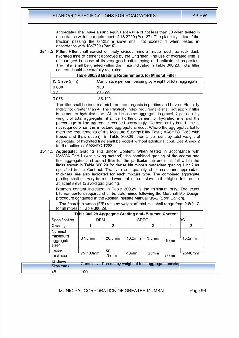
8/19/2019 MCGM Road Spec Volume -II
http://slidepdf.com/reader/full/mcgm-road-spec-volume-ii 100/176
STANDARD SPECIFICATIONS FOR ROAD WORKS SP-RW
MUNICIPAL CORPORATION OF GREATER MUMBAI Page 96
aggregates shall have a sand equivalent value of not less than 50 when tested inaccordance with the requirement of 1S:2720 (Part-37). The plasticity index of thefraction passing the 0.425mm sieve shall not exceed 4 when tested inaccordance with 1S:2720 (Part-5).
354.4.2 Filler : Filler shall consist of finely divided mineral matter such as rock dust,hydrated lime or cement approved by the Engineer. The use of hydrated lime isencouraged because of its very good anti-stripping and antioxidant properties.The Filler shall be graded within the limits indicated in Table 300.28. Total fillercontent should be carefully regulated.
Table 300.28 Grading Requirements for Mineral Filler
IS Sieve (mm) Cumulative per cent passing by weight of total aggregate
0.600 100
0.3 95-100
0.075 85-100
The filler shall be inert material free from organic impurities and have a PlasticityIndex not greater than 4. The Plasticity Index requirement shall not apply if filleris cement or hydrated lime. When the coarse aggregate is gravel, 2 per cent byweight of total aggregate, shall be Portland cement or hydrated lime and thepercentage of fine aggregate reduced accordingly. Cement or hydrated lime isnot required when the limestone aggregate is used. Where the aggregates fail tomeet the requirements of the Moisture Susceptibility Test ( AASHTO T283 withfreeze and thaw option) in Table 300.29, then 2 per cent by total weight ofaggregate, of hydrated lime shall be added without additional cost. See Annex 2for the outline of AASHTO T283.
354.4.3 Aggregate: Grading and Binder Content: When tested in accordance withIS:2386 Part-1 (wet sieving method), the combined grading of the coarse and
fine aggregates and added filler for the particular mixture shall fall within thelimits shown in Table 300.29 for dense bituminous macadam grading 1 or 2 asspecified in the Contract. The type and quantity of bitumen and appropriatethickness are also indicated for each mixture type. The combined aggregategrading shall not vary from the lower limit on one sieve to the higher limit on theadjacent sieve to avoid gap grading.
Bitumen content indicated in Table 300.29 is the minimum only. The exactbitumen content required shall be determined following the Marshall Mix Designprocedure containecl in the Asphalt Institute Manual MS-2 (Sixth Edition).
The fines to bitumen (F/B) ratio by weight of total mix shall range from 0.6(01.2for all mixes in Table 300.29.
Table 300.29 Aggregate Grading and- Bitumen ContentSpecification DBM SDBC BC
Grading I 2 I 2 1 2
Nominalmaximumaggregatesize*
37.5mm 26.5mm 13.2mm 9.5mm19mm
13.2mm
Layerthickness
75·100mm50-75mm
40mm 25mm50mm
25/40mm
IS SieveSize(mm)
Cumulative Percent by weight of total aggregate passing
45 100
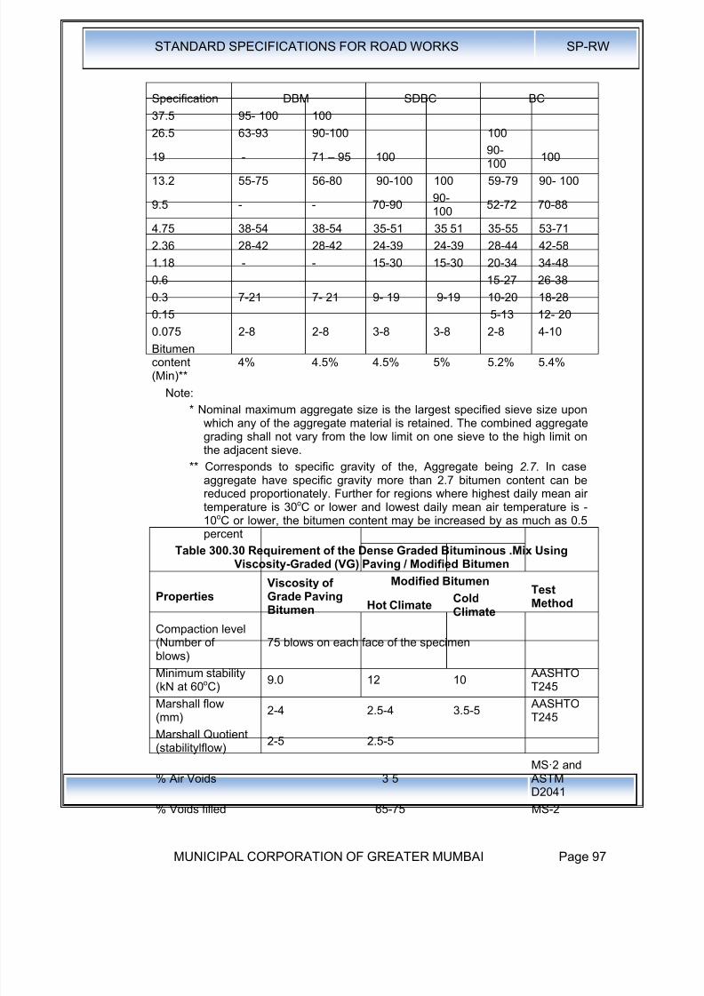
8/19/2019 MCGM Road Spec Volume -II
http://slidepdf.com/reader/full/mcgm-road-spec-volume-ii 101/176
STANDARD SPECIFICATIONS FOR ROAD WORKS SP-RW
MUNICIPAL CORPORATION OF GREATER MUMBAI Page 97
Specification DBM SDBC BC
37.5 95- 100 100
26.5 63-93 90-100 100
19 - 71 – 95 10090-100 100
13.2 55-75 56-80 90-100 100 59-79 90- 100
9.5 - - 70-9090-100
52-72 70-88
4.75 38-54 38-54 35-51 35 51 35-55 53-71
2.36 28-42 28-42 24-39 24-39 28-44 42-58
1.18 - - 15-30 15-30 20-34 34-48
0.6 15-27 26-38
0.3 7-21 7- 21 9- 19 9-19 10-20 18-28
0.15 5-13 12- 200.075 2-8 2-8 3-8 3-8 2-8 4-10
Bitumencontent(Min)**
4% 4.5% 4.5% 5% 5.2% 5.4%
Note:
* Nominal maximum aggregate size is the largest specified sieve size uponwhich any of the aggregate material is retained. The combined aggregategrading shall not vary from the low limit on one sieve to the high limit onthe adjacent sieve.
** Corresponds to specific gravity of the, Aggregate being 2.7. In caseaggregate have specific gravity more than 2.7 bitumen content can bereduced proportionately. Further for regions where highest daily mean airtemperature is 30oC or lower and Iowest daily mean air temperature is -10oC or lower, the bitumen content may be increased by as much as 0.5percent
Table 300.30 Requirement of the Dense Graded Bituminous .Mix UsingViscosity-Graded (VG) Paving / Modified Bitumen
PropertiesViscosity ofGrade PavingBitumen
Modified BitumenTestMethodHot Climate
ColdClimate
Compaction level(Number ofblows)
75 blows on each face of the specimen
Minimum stability(kN at 60oC)
9.0 12 10 AASHTOT245
Marshall flow(mm)
2-4 2.5-4 3.5-5 AASHTOT245
Marshall Quotient(stabilitylflow)
2-5 2.5-5
% Air Voids 3 5MS·2 and ASTM
D2041% Voids filled 65-75 MS-2
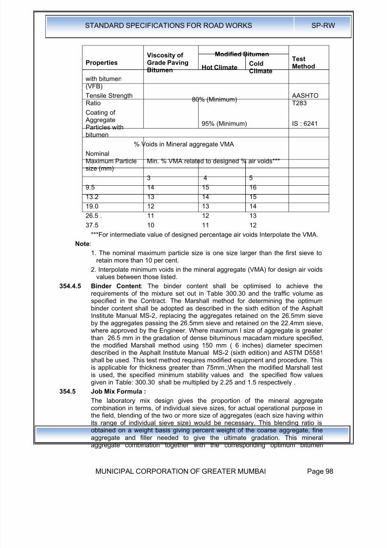
8/19/2019 MCGM Road Spec Volume -II
http://slidepdf.com/reader/full/mcgm-road-spec-volume-ii 102/176
STANDARD SPECIFICATIONS FOR ROAD WORKS SP-RW
MUNICIPAL CORPORATION OF GREATER MUMBAI Page 98
PropertiesViscosity ofGrade PavingBitumen
Modified BitumenTestMethodHot Climate
ColdClimate
with bitumen
(VFB)Tensile StrengthRatio
80% (Minimum) AASHTOT283
Coating of AggregateParticles withbitumen
95% (Minimum) IS : 6241
% Voids in Mineral aggregate VMA
NominalMaximum Particlesize (mm)
Min. % VMA related to designed % air voids***
3 4 5
9.5 14 15 16
13.2 13 14 15
19.0 12 13 14
26.5 . 11 12 13
37.5 10 11 12
***For intermediate value of designed percentage air voids Interpolate the VMA.
Note:
1. The nominal maximum particle size is one size larger than the first sieve to
retain more than 10 per cent.2. Interpolate minimum voids in the mineral aggregate (VMA) for design air voids
values between those listed.
354.4.5 Binder Content: The binder content shall be optimised to achieve therequirements of the mixture set out in Table 300.30 and the traffic volume asspecified in the Contract. The Marshall method for determining the optimumbinder content shall be adopted as described in the sixth edition of the AsphaltInstitute Manual MS-2, replacing the aggregates retained on the 26.5mm sieveby the aggregates passing the 26.5mm sieve and retained on the 22.4mm sieve,where approved by the Engineer. Where maximum l size of aggregate is greaterthan 26.5 mm in the gradation of dense bituminous macadam mixture specified,
the modified Marshall method using 150 mm ( 6 inches) diameter specimendescribed in the Asphalt Institute Manual MS-2 (sixth edition) and ASTM D5581shall be used. This test method requires modified equipment and procedure. Thisis applicable for thickness greater than 75mm.;When the modified Marshall testis used, the specified minimum stability values and the specified flow valuesgiven in Table: 300.30 shall be multiplied by 2.25 and 1.5 respectively .
354.5 Job Mix Formula :
The laboratory mix design gives the proportion of the mineral aggregatecombination in terms, of individual sieve sizes, for actual operational purpose inthe field, blending of the two or more size of aggregates (each size having withinits range of individual sieve size) would be necessary. This blending ratio isobtained on a weight basis giving percent weight of the coarse aggregate, fineaggregate and filler needed to give the ultimate gradation. This mineralaggregate combination together with the corresponding optimum bitumen
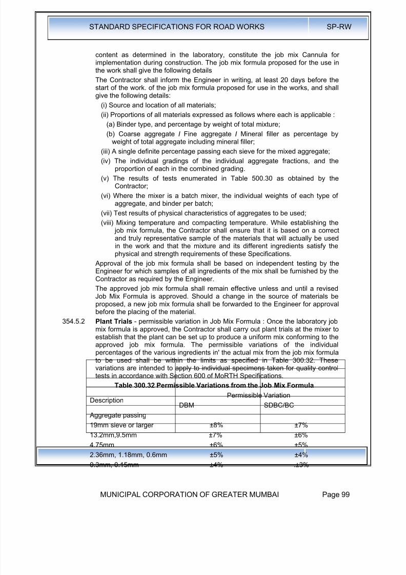
8/19/2019 MCGM Road Spec Volume -II
http://slidepdf.com/reader/full/mcgm-road-spec-volume-ii 103/176
STANDARD SPECIFICATIONS FOR ROAD WORKS SP-RW
MUNICIPAL CORPORATION OF GREATER MUMBAI Page 99
content as determined in the laboratory, constitute the job mix Cannula forimplementation during construction. The job mix formula proposed for the use inthe work shall give the following details
The Contractor shall inform the Engineer in writing, at least 20 days before the
start of the work. of the job mix formula proposed for use in the works, and shallgive the following details:
(i) Source and location of all materials;
(ii) Proportions of all materials expressed as follows where each is applicable :
(a) Binder type, and percentage by weight of total mixture;
(b) Coarse aggregate I Fine aggregate I Mineral filler as percentage byweight of total aggregate including mineral filler;
(iii) A single definite percentage passing each sieve for the mixed aggregate;
(iv) The individual gradings of the individual aggregate fractions, and theproportion of each in the combined grading.
(v) The results of tests enumerated in Table 500.30 as obtained by theContractor;
(vi) Where the mixer is a batch mixer, the individual weights of each type ofaggregate, and binder per batch;
(vii) Test results of physical characteristics of aggregates to be used;
(viii) Mixing temperature and compacting temperature. While establishing the job mix formula, the Contractor shall ensure that it is based on a correctand truly representative sample of the materials that will actually be usedin the work and that the mixture and its different ingredients satisfy thephysical and strength requirements of these Specifications.
Approval of the job mix formula shall be based on independent testing by the
Engineer for which samples of all ingredients of the mix shall be furnished by theContractor as required by the Engineer.
The approved job mix formula shall remain effective unless and until a revisedJob Mix Formula is approved. Should a change in the source of materials beproposed, a new job mix formula shall be forwarded to the Engineer for approvalbefore the placing of the material.
354.5.2 Plant Trials - permissible variation in Job Mix Formula : Once the laboratory jobmix formula is approved, the Contractor shall carry out plant trials at the mixer toestablish that the plant can be set up to produce a uniform mix conforming to theapproved job mix formula. The permissible variations of the individualpercentages of the various ingredients in' the actual mix from the job mix formulato be used shall be within the limits as specified in Table 300.32. Thesevariations are intended to apply to individual specimens taken for quality controltests in accordance with Section 600 of MoRTH Specifications.
Table 300.32 Permissible Variations from the Job Mix Formula
DescriptionPermissible Variation
DBM SDBC/BC
Aggregate passing
19mm sieve or larger ±8% ±7%
13.2mm,9.5mm ±7% ±6%
4.75mm ±6% ±5%
2.36mm, 1.18mm, 0.6mm ±5% ±4%0.3mm, 0.15mm ±4% .±3%

8/19/2019 MCGM Road Spec Volume -II
http://slidepdf.com/reader/full/mcgm-road-spec-volume-ii 104/176
STANDARD SPECIFICATIONS FOR ROAD WORKS SP-RW
MUNICIPAL CORPORATION OF GREATER MUMBAI Page 100
DescriptionPermissible Variation
DBM SDBC/BC
0.075mm ±2% ± 1.5%
Binder Content ±0.3% ±0.3%
Mixing Temperature ± 10° C ± 10° C
Once the plant trials have demonstrated the capability of the plant, and the trialsare approved, the laying operation may commerce. Over the period of the firstmonth of production for laying on the works, the Engineer shall require additionaltesting of the product to establish the reliability and consistency of the plant.
354.6 Scope: This clause specifies the construction of Dense Graded BituminousMacadam (DBM), for use mainly, but not exclusively, in base/binder and profilecorrective courses, DBM is also intended for use as road base material. Thiswork shall consist of construction in a single or multiple layers of DBM on apreviously prepared base or subbase. The thickness of a single layer shall be50mm to 100mm.
354.7 Laying Trials : Once the plant trials have been successfully completed andapproved, the Contractor shall carry out laying trials, to demonstrate that theproposed mix can. be successfully laid, and compacted all in accordance withClause 318. The laying trial shall be carried out on a suitable area which is not toform part of the works, unless specifically approved in writing, by the Engineer.The area. of the laying trials shall be a minimum of 100 sqm of constructionsimilar to that of the project road, and it shall be in all respects, particularlycompaction, the same as the project construction, on which the bituminousmaterial is to be laid.
The trials establish that the proposed laying plan, compaction plan, andmethodology are capable of producing satisfactory results. The density of
finished paving layer should not be less than the 92% of the average density(Sample size N=2) based on theoretical maximum specific gravity of the loosemix (Gmm) obtained on the day of trial following ASTM D2041. See Annex 3 forthe outline of ASTM D2041.
The Contractor shall previously inform the Engineer of the proposed method forlaying and compacting the material. The plant trials shall then establish if theproposed laying plant, compaction plant, and methodology is capable ofproducing satisfactory results. The density of the finished paving layer shall bedetermined by taking cores, no sooner than 24 hours after laying, or by otherapproved method.
Once the laying trials have been approved, the same plant and methodology
shall be applied to the laying of the material on the project, and no variation ofeither shall be acceptable, unless approved in writing by the Engineer, who mayat his discretion require further laying trials.
354.8 Construction Operations :
354.8.1 Weather and Seasonal Limitations: The provisions of Clause 318.4.1 shallapply.
354.8.2 Preparation of Base : The base on which Dense Graded Bituminous Material isto be laid shall: be prepared in accordance with Clauses 318.5and 600asappropriate, or as directed by the Engineer. The surface shall be thoroughlyswept clean by a mechanical broom, and the dust removed by compressed air.In locations where mechanical broom cannot access, other approved methods
shall be used as directed by the Engineer.
8/19/2019 MCGM Road Spec Volume -II
http://slidepdf.com/reader/full/mcgm-road-spec-volume-ii 105/176
STANDARD SPECIFICATIONS FOR ROAD WORKS SP-RW
MUNICIPAL CORPORATION OF GREATER MUMBAI Page 101
354.8.3 Geo-Synthetics : Where Geo-synthetics are specified in the Contract, this shallbe in accordance with the requirements stated in Clause 260.
354.8.4 Stress Absorbing Layer : Where a stress absorbing layer is specified in theContract, this shall be applied in accordance with the requirements of Clause
316.354.8.4.1 Profile correcting coarse:
Profile correcting Course: Depending upon requirement, profile-correcting coursefor correcting the existing pavement profile shall be laid either as a separatelayer or as a composite layer with varying thickness. Where the maximumthickness of the profile corrective course is less than 40 mm, the profilecorrective course shall be laid as an integral part of the overlaying layer. In othercases the profile corrective course shall be constructed as a separate layer.When it is laid as a separate layer, type of material for the use as the profilecorrective course may differ.
354.8.5 Prime Coat : Where the material on which the dense bituminous macadam is tobe laid is other than a bitumen bound layer, a prime coat shall be applied, asspecified, in accordance with the provisions of Clause 313, or as directed by theEngineer.
354.8.6 Tack Coat : Where the material on which the dense bituminous macadam is tobe placed is bitumen bound surface, a tack coat shall be applied as specified, inaccordance with the provisions of Clause 314, or as directed by the Engineer.
354.8.7 Mixing and Transportation of the mixture : The provisions as specified inClauses 318.2.1 and 318.3.1 shall apply.
354.8.8 Spreading: The provisions of Clauses 318.6 shall apply.
354.8.9 Rolling: The general provisions of Clauses 318.8 shall apply, as modified by theapproved by laying trials. The compaction process shall be carried out by the
same plant, and .using the same method, as approved in the laying trials, whichmay be varied only with the express approval of the Engineer in writing.
354.8.10 Opening to Traffic : The newly laid surface shall not be open to traffic for atleast 24 hrs. after laying and completion of compaction, without the expressapproval of the Engineer in writing.
354.8.11 Surface Finish and Quality Control of Work : The surface finish of thecompleted construction shall conform to the requirements of Clause 600. Allmaterials and workmanship shall comply with the provisions set out in Section600.
354.8.12 Arrangements for Traffic : During the period of construction, arrangements fortraffic shall be made in accordance with the provisions of Clause 30.
354.8.13 Measurements for Payment : Dense Graded Bituminous Materials shall bemeasured as finished work wither in cubic metres, tons or by the square metre ata specified thickness as detailed on the Contract drawings, or documents, or asdirected by the Engineer.
354.8.14 Rate: The contract unit rate for Dense Graded Bituminous Macadam shall bepayment in full for carrying out the all required operations as specified, and shallinclude, but not necessarily limited to all components listed in Clause 318.11.The rate shall include the provision of bitumen, at 4.25 per cent by weight of thetotal mixture.The variation in actual percentage of bitumen used will be assessedand the payment adjusted, up or down, accordingly.

8/19/2019 MCGM Road Spec Volume -II
http://slidepdf.com/reader/full/mcgm-road-spec-volume-ii 106/176
STANDARD SPECIFICATIONS FOR ROAD WORKS SP-RW
MUNICIPAL CORPORATION OF GREATER MUMBAI Page 102
360.0 Wearing Coat
361.0 Open Graded Premix Surfacing using Paving Grade Bitumen
361.1.1 Scope: This work shall consist of the preparation, laying and compaction of anopen-graded premix surfacing material of 20mm thickness composed of small-sized aggregate premixed with a bituminous binder on a previously preparedbase, in accordance with the requirements of these Specifications, to serve as awearing course.
361.1.2 Materials:
361.1.2.1 Binder : The binder shall be a paving grade bitumen of a suitable grade asspecified in the Clause No. 318.1.4, or as directed by the Engineer, andsatisfying the requirements of IS:73. The binder for track coat shall be rapidsetting cationic bitumen emulsion conforming to IS:8887. ( As per Clause 3.1.1 ofIRC:14-2004). The quantity of binder for track coat and premix binder is given inTable:300.33.1 and Table:300.33.2 below respectively. ( As per Table: 4 andTable:5 of IRC:14-2004).
Table 300.33.1 Quantity of Binders For tack Coat
Item Quantity per 10m3 area of road surface
On a granular Surface (Primed) 2.5 to 3.5 kg
On an existing black surface* 2.0 to 3.0 kg
* In case of the existing black top surface is extremely rich in binder, or fatty, thetack coat may be eliminated in hot climate regions at the discretion of theEngineer in Charge , if a good bond between the existing surface and thesuperimposed layer can be ensured.
Table 300.33.2 Quantity of Binders For PREMIX CARPET
Item Quantity per 10m3 area of road surface
For 13.5 mm size coarse aggregates 9.5 kg @ 52 kg per m3
For 11.2 mm size coarse aggregates 5.1 kg @ 56 kg per m3
Total 14.6 kg
361.1.2.2 Aggregate: The aggregate shall conform to Clause No.318.1 except that thewater absorption shall be limited to a maximum of 1 per cent. The PolishedStone Value, as measured by the test in IS 812 (Part- 114), shall not be less than55.
361.1.2.2.1 Proportioning of Materials : The materials shall be proportioned inaccordance with Table 300.34.
Table 300.34 Quantities of Materials required for 10m2 of Road Surface for
20mm thick Open Graded Premix Surfacing using Paving Grade Bitumen orEmulsion
Aggregates Quantity
i. Nominal Stone Size 13.2mm (passing 22.4mm sieve and retainedon 11.2mm sieve)
0.18m3
ii. Nominal Stone Size 11.2mm (passing 13.2mm sieve andretained on 5.6mm sieve)
0.09m3
Total 0.27m3
Binder (quantities in terms of straight run bitumen)
a) For 0.18 m3 of 13.2mm nominal size stone at 52 Kg. bitumen per
m3
9.5 Kg.
b) For 0.09 m3 of 11.2mm nominal size stone at 56 Kg. Bitumen per 5.1 Kg.
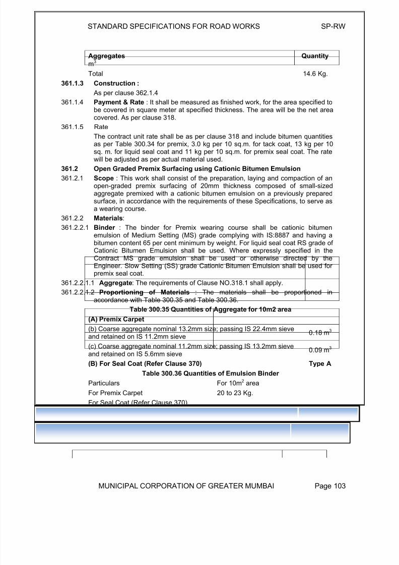
8/19/2019 MCGM Road Spec Volume -II
http://slidepdf.com/reader/full/mcgm-road-spec-volume-ii 107/176
STANDARD SPECIFICATIONS FOR ROAD WORKS SP-RW
MUNICIPAL CORPORATION OF GREATER MUMBAI Page 103
Aggregates Quantity
m3
Total 14.6 Kg.
361.1.3 Construction :
As per clause 362.1.4
361.1.4 Payment & Rate : It shall be measured as finished work, for the area specified tobe covered in square meter at specified thickness. The area will be the net areacovered. As per clause 318.
361.1.5 Rate
The contract unit rate shall be as per clause 318 and include bitumen quantitiesas per Table 300.34 for premix, 3.0 kg per 10 sq.m. for tack coat, 13 kg per 10sq. m. for liquid seal coat and 11 kg per 10 sq.m. for premix seal coat. The ratewill be adjusted as per actual material used.
361.2 Open Graded Premix Surfacing using Cationic Bitumen Emulsion
361.2.1 Scope : This work shall consist of the preparation, laying and compaction of anopen-graded premix surfacing of 20mm thickness composed of small-sizedaggregate premixed with a cationic bitumen emulsion on a previously preparedsurface, in accordance with the requirements of these Specifications, to serve asa wearing course.
361.2.2 Materials:
361.2.2.1 Binder : The binder for Premix wearing course shall be cationic bitumenemulsion of Medium Setting (MS) grade complying with IS:8887 and having abitumen content 65 per cent minimum by weight. For liquid seal coat RS grade ofCationic Bitumen Emulsion shall be used. Where expressly specified in theContract MS grade emulsion shall be used or otherwise directed by the
Engineer. Slow Setting (SS) grade Cationic Bitumen Emulsion shall be used forpremix seal coat.
361.2.2.1.1 Aggregate: The requirements of Clause NO.318.1 shall apply.
361.2.2.1.2 Proportioning of Materials : The materials shall be proportioned inaccordance with Table 300.35 and Table 300.36.
Table 300.35 Quantities of Aggregate for 10m2 area
(A) Premix Carpet
(b) Coarse aggregate nominal 13.2mm size; passing IS 22.4mm sieveand retained on IS 11.2mm sieve
0.18 m3
(c) Coarse aggregate nominal 11.2mm size; passing IS 13.2mm sieveand retained on IS 5.6mm sieve
0.09 m3
(B) For Seal Coat (Refer Clause 370) Type A
Table 300.36 Quantities of Emulsion Binder
Particulars For 10m2 area
For Premix Carpet 20 to 23 Kg.
For Seal Coat (Refer Clause 370)
(a) for liquid seal coat 12 to 14 Kg.
(b) for premix seal coat 10 to 12 Kg.
361.2.3 Construction Operations:
361.2.3.1 Weather and Seasonal Limitations : The provisions of Clause 318.4.1 shall
apply.
8/19/2019 MCGM Road Spec Volume -II
http://slidepdf.com/reader/full/mcgm-road-spec-volume-ii 108/176
STANDARD SPECIFICATIONS FOR ROAD WORKS SP-RW
MUNICIPAL CORPORATION OF GREATER MUMBAI Page 104
361.2.3.2 Preparation of Base: The underlying surface on which the bituminous surfacing isto be laid shall be prepared, shaped and conditioned to the specified lines, gradeand cross-section in accordance with Clause
318.10. A prime coat where needed shall be applied in accordance with Clause 313 as
directed by the Engineer.361.2.3.3 Tack Coat: A tack coat shall be applied over the base preparatory to laying ofthe surfacing in accordance with the requirements of Clause 314.
361.2.3.4 Preparation of Premix : Hot mix plant of appropriate capacity and type shall beused for the preparation of the mix material. The hot mix plant shall haveseparate dryer arrangement for heating aggregate.
The temperature of the binder at the time of mixing shall be in the range of 150°Cto 163°C and that of the aggregate in the range of 155°C to 163°C provided thatthe difference in temperature between the binder and aggregate at no timeexceeds 14°C. Mixing shall be thorough to ensure that a homogeneous mixtureis obtained in which all particles of the aggregates are coated uniformly and thedischarge temperature of mix shall be between 130°C and 160°C.
The mix shall be immediately transported from the mixer to the point of use insuitable vehicles or hand barrows. The vehicles employed for transport shall beclean and the mix being transported covered in transit if so directed by theEngineer.
361.2.3.5 Spreading and Rolling : The pre mixed material shall be spread by suitablemeans to the desired thickness, grades and cross-full (camber) making dueallowance for any extra quantity required to fill up depressions, if any. The cross-fall should be checked by means of camber boards and irregularities levelled out.Excessive use of blades or rakes should be avoided. As soon as sufficient lengthof bituminous material has been laid, rolling shall commence with 8-10 tonnerollers, smooth wheel tandem type, or other approved equipment. Rolling shall
begin at the edge and progress toward the centre longitudinally, except that onsuper elevated and unidirectional cambered portions, it shall progress from thelower to upper edge parallel to the centre line of the pavement.
When the roller has passed over the whole area once, any high spots ordepressions, . which become apparent, shall be corrected by removing or addingpremixed materials. Rolling shall then be continued until the entire surface hasbeen rolled and all the roller marks eliminated. In each pass of the roller, thepreceding track shall be overlapped uniformly by at least 1/3 width. The rollerwheels shall be kept damp to prevent the premix from adhering to the wheels. Inno case shall fuel/lubricating oil be used for this purpose. Excess use of water forthis purpose shall also be avoided.
Rollers shall not stand on newly laid material. Rolling operations shall becompleted in every respect before the temperature of the mix falls below 100°C. joints along and transverse to the surfacing laid and compacted earlier shall becut vertically to their full depth so as to expose fresh surface which shall bepainted with a thin coat of appropriate binder before the new mix is placedagainst it.
361.2.3.6 Seal Coat: A seal coat conforming to Clause 370 of the type specified in theContract shall be applied to the surface immediately after laying the surfacing.
361.2.3.7 Opening to Traffic: No traffic shall be allowed on the road until the seal coat hasbeen laid. After the seal coat is laid, the road may be opened to traffic accordingto Clause 30.
361.2.3.8 Surface Finish and Quality Control of Work: The surface finish of theconstruction shall conform to the requirements of Clause 600. For control on the

8/19/2019 MCGM Road Spec Volume -II
http://slidepdf.com/reader/full/mcgm-road-spec-volume-ii 109/176
STANDARD SPECIFICATIONS FOR ROAD WORKS SP-RW
MUNICIPAL CORPORATION OF GREATER MUMBAI Page 105
quality of materials supplied and the works carried out, the relevant provisions ofSection 600shall apply.
361.2.3.9 Arrangements for Traffic : During the period of construction, arrangements fortraffic shall be made in accordance with the provisions of Clause 30.
361.2.3.10 Measurements for Payment : Open Graded Premix Surfacing shall bemeasured as finished work, for the area instructed to be covered, in squaremetres. The area will be the net area covered and all allowances for wastageand cutting of joints shall be deemed to be included in the rate.
361.2.3.11 Rate: The contract unit rate for Open Graded Premix Surfacing shall be paymentin full for carrying out the required operations including full compensation for allcomponents listed in Clause 318.11 ..
362.0 Close Graded Premix Surfacing or MSS
362.1 This work shall consist of the preparation, laying and compaction of a close-graded premix surfacing material of 20mm thickness composed 'of gradedaggregates premixed with a bituminous binder on a previously prepared surface,
in accordance with the requirements of these Specifications, to serve as awearing course.
Close graded premix shall be of Type A or Type B as specified in the contractdocuments.
362.1.1 Binder : The provisions of Clause NO.361.2.2.1 shall apply.
362.1.2 Coarse Aggregates : The aggregate shall conform to Clause No.318.1.1 exceptthat the water absorption shall be limited to maximum of 1 per cent. The polishedstone value, as measured by the test in IS:812 (Part-114) shall not be less than55.
362.1.3 Fine Aggregates : The fine aggregates shall consist of crushed rock quarrysands, natural gravel/sand or a mixture of both. These shall be clean, hard,
durable, un-coated, mineral particles, dry and free from injurious, soft or flakyparticles and organic or deleterious substances as per Clause 318.1.2.
362.1.3.1 Aggregate Gradation: The coarse and fine aggregates shall be so graded orcombined as to conform to one or the other gradings shown in Table 300-37, asspecified in the contract.
Table 300.37
IS Sieve Designation (mm) Cumulative Per Cent by weight of totalaggregate passing
Type A Type B
13.2mm - 100
11.2mm 100 88-1005.6mm 52-88 31-52
2.8mm 14-38 5-25
0.090mm 0-5 0-5
362.1.3.2 Proportioning of Materials: The total quantity of aggregates used for Type A or Bclose-graded premix surfacing shall be 0.27 cube metre per 10 square metrearea. The quantity of binder used for premixing in terms of straight-run bitumenshall be 22.0 Kg and 19.0 Kg per 10 Square Metre area for Type A and Type Bsurfacing respectively.
362.1.4 Construction Operations:
362.1.4.1 Weather and Seasonal Limitations: The provisions of Clause 318.4.1 shallapply.

8/19/2019 MCGM Road Spec Volume -II
http://slidepdf.com/reader/full/mcgm-road-spec-volume-ii 110/176

8/19/2019 MCGM Road Spec Volume -II
http://slidepdf.com/reader/full/mcgm-road-spec-volume-ii 111/176

8/19/2019 MCGM Road Spec Volume -II
http://slidepdf.com/reader/full/mcgm-road-spec-volume-ii 112/176
STANDARD SPECIFICATIONS FOR ROAD WORKS SP-RW
MUNICIPAL CORPORATION OF GREATER MUMBAI Page 108
Table 300.39 Physical Requirements for Coarse Aggregates for Semi·-DenseBituminous Concrete Pavement Layers
Property Test Specification
Cleanliness (Dust) Grain size analysisMax 5% passing
0.075mm sieve
Particle shapeFlakiness andElongation Index(Combined)
Max 30%
Strength
Los Angeles AbrasionValue
Max 35%
Aggregate Impact Value Max 27%
Polishing Polished Stone Value Min 55
Water Absorption Water Absorption Max 2%
Stripping
Coating and Stripping of
Bitumen AggregateMixtures
Minimum retained
coating 95%
Water SensitivityRetained TensileStrength
Min 80%
The requirements for minimum per cent voids in mineral aggregate (VMA) are setout in Table 300.31 .
363.3.2 Binder Content: The binder content shall be optimized to achieve therequirements of the mixture set out in Table 300.39 and the traffic volume asspecified in the Contract. The Marshall method for determining the optimumbinder content shall be adopted as described in the Asphalt Institute Manual MS-2, replacing the aggregates retained on the 26.5mm sieve and retained on the
22.4mm sieve, where approved by the Engineer.Table 300.40 Composition of Semi-Dense Bituminous Concrete Pavement
Layers
Grading 1 2
Nominal Aggregate Size 13mm 10mm
Layer Thickness 35-40mm 25-30mm
IS Sieve (mm) Cumulative % by weight of total aggregate passing
45
37.5
26.5
19 100
13.2 90-100 100
9.5 70-90 90-100
4.75 35-51 35-51
2.36 24-39 24-39
1.18 15-30 15-30
0.6 - -
0.3 9-19 9-19
0.15 - -
0.075 3-8 3-8
Bitumen Content % by Min. 4.5 Min. 5.0
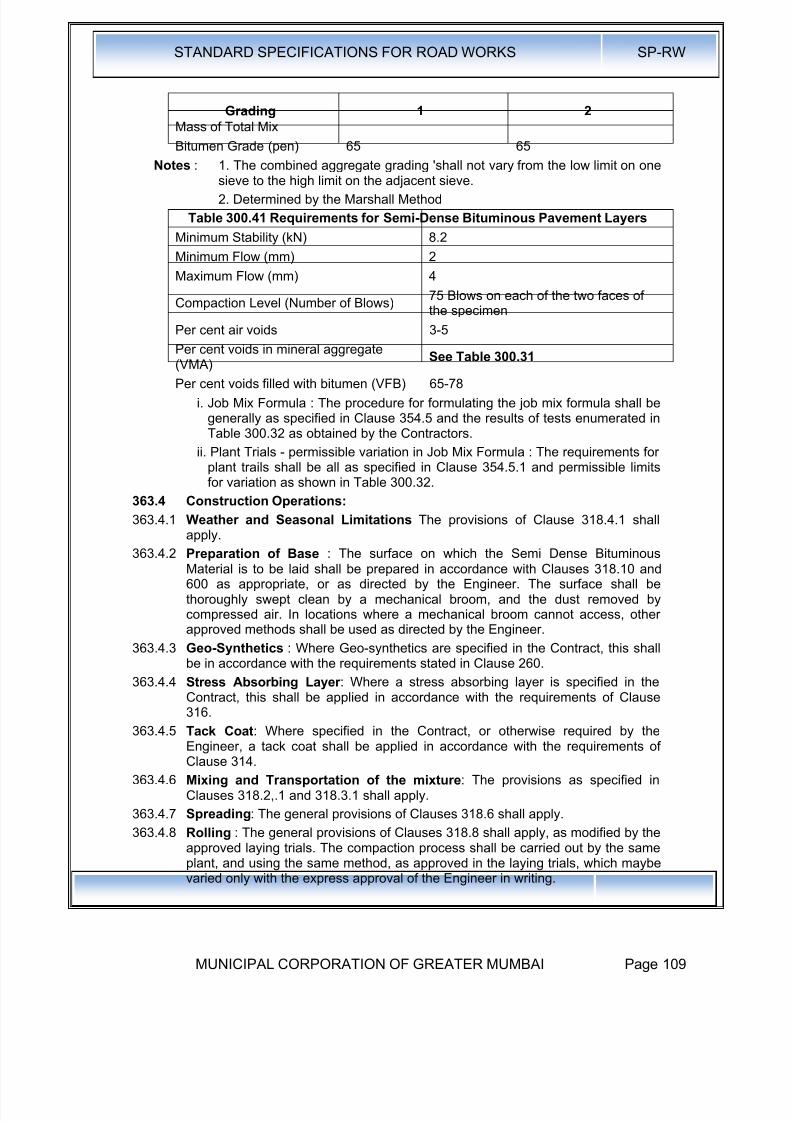
8/19/2019 MCGM Road Spec Volume -II
http://slidepdf.com/reader/full/mcgm-road-spec-volume-ii 113/176

8/19/2019 MCGM Road Spec Volume -II
http://slidepdf.com/reader/full/mcgm-road-spec-volume-ii 114/176
STANDARD SPECIFICATIONS FOR ROAD WORKS SP-RW
MUNICIPAL CORPORATION OF GREATER MUMBAI Page 110
363.4.9 Opening to Traffic: The newly laid surface shall not be open to traffic for at least24 hrs. after laying and the completion of compaction, without the expressapproval of the Engineer in writing.
363.4.10 Surface Finish and Quality Control of Work : The surface finish of the
completed construction shall conform to the requirements of Clause 600. Allmaterials and workmanship shall comply with the provisions set out in Section600.
363.4.11 Arrangements for Traffic : During the period of construction, arrangements fortraffic shall be made in accordance with the provisions of Clause 30.
363.4.12 Measurements for Payment : Dense Graded Bituminous Materials shall bemeasured as finished work wither in cubic metres, tons or by the square metre ata specified thickness as detailed on the Contract drawings, or documents, or asdirected by the Engineer.
363.4.13 Rate : The contract unit rate shall be payment as specified in Clause 354.10.14,except that the rate shall include the provision of bitumen at 4.75 per cent, byweight of total mixture. The variance in actual percentage of bitumen used will beassessed and the payment adjusted up or down, accordingly.
364.0 Bituminous Concrete:
364.1 Scope: This clause specifies the construction of Bituminous Concrete, for use inwearing and profile corrective courses. This work shall consist of construction ina single or multiple layers of bituminous concrete on a previously preparedbituminous bound surface.
364.2 Bitumen : The bitumen shall be paving bitumen of Penetration grade complyingwith Indian Standard Specification for Paving Bitumen, IS:73 and of thepenetration indicated in Table 300.43, for bituminous concrete, or this bitumen asmodified by one of the methods specified in Clause 311, or as otherwisespecified in the Contract. Guidance on the selection of an appropriate grade ofbitumen is given in the manual for Construction and Supervision of BituminousWorks.
364.2.1 Coarse Aggregates : The coarse aggregates shall be generally as specified inClause 354.1, except that the aggregates shall satisfy the physical requirementsof Table 300.44.
364.2.2 Fine Aggregates : The fine aggregates shall be all as specified in Clause 354.2.
364.2.3 Filler : Filler shall be generally as specified in Clause 354.3. Where theaggregates fail to meet the requirements of the water sensitivity test in Table300.44 then 2 per cent by total weight of aggregate, of hydrated lime shall beadded without additional cost.
364.2.4 Aggregate Grading and Binder Content: When tested in accordance withIS:2386 (Part-1) (Wet Grading Method), the combined grading of the coarse andfine aggregates and added filler shall fall within the limits shown in Table 300.43for gradings 1 or 2 as specified in the Contract.
Table 300.42 Requirements for Dense Bituminous Pavement Layers
Minimum Stability (kN) 9.0
Minimum Flow (mm) 2
Maximum Flow (mm) 4
Compaction Level (Number of Blows)75 Blows on each of the two faces ofthe specimen
Per cent air voids 3-6Per cent voids in mineral aggregate See Table 300.31

8/19/2019 MCGM Road Spec Volume -II
http://slidepdf.com/reader/full/mcgm-road-spec-volume-ii 115/176
STANDARD SPECIFICATIONS FOR ROAD WORKS SP-RW
MUNICIPAL CORPORATION OF GREATER MUMBAI Page 111
(VMA)
Per cent voids filled with bitumen (VFB) 65-75
Loss of Stability on immersion in waterat 60°C (ASTM D 1075)
Min. 75 per cent retained strength
Table 300.43 Composition of Bituminous Concrete Pavement Layers
Grading 1 2
Nominal Aggregate Size 19mm 13mm
Layer Thickness 50mm 40mm
IS· Sieve (mm) Cumulative % by weight of total aggregate passing
45
37.50
26.50 100
19 79-100 100
13.20 59-79 79-1009.5 52-72 70-88
4.75 35-55 53-71
2.36 28-44 42-58
1.18 20-34 34-48
0.6 15-27 26-38
0.3 10-20 18-28
0.15 5-13 12-20 :
0.0752-8 (Lime powder orOPC/PPC cement, fillershall be 2%)
4-10 (Lime powder orOPC/PPC cement, fillershall be 2%)
Bitumen Content, % byweight of total mixture
5.0 - 6.0 Min 6
Bitumen Grade (pen) 65 65
Notes: 1. The combined aggregate grading shall not vary from the low limit on onesieve to the high limit on the adjacent sieve.
2. Determined by the Marshall Method
364.3 Mixture Design:
364.3.1 Requirements for the mixture : Apart from conformity with the grading andquality requirements for individual ingredients, the mixture shall meet the
requirements set out in Table 300.42. The requirements for minimum per centvoids in mineral aggregate (VMA) are set out in Table 300.31
364.3.2 Binder Content: The binder content shall be optimized to achieve therequirements of the mixture set out in Table 300.44 and the traffic volume asspecified in the Contract. The Marshall method for determining the optimumbinder content shall be adopted as described in the Asphalt Institute Manual MS-2, replacing the aggregates retained on the 26.5mm sieve and retained on the22.4mm sieve, where approved by the Engineer.
364.3.3 Job Mix Formula: The procedure for formulating the job mix formula shall begenerally as specified in Clause 354.5 and the results of tests enumerated inTable 300.44 as obtained by the Contractors.

8/19/2019 MCGM Road Spec Volume -II
http://slidepdf.com/reader/full/mcgm-road-spec-volume-ii 116/176
STANDARD SPECIFICATIONS FOR ROAD WORKS SP-RW
MUNICIPAL CORPORATION OF GREATER MUMBAI Page 112
Table 300.44 Physical Requirements for Coarse Aggregates forBituminousConcrete Pavement Layers
Property Test Specification
Cleanliness (Dust)1 Grain size analysisMax 5% passing
0.075mm sieve
Particle shapeFlakiness andElongation2 Index(Combined)
Max 30% (Combined)
Strength * IS:2386 Part-4*
Los Angeles AbrasionValue 3
Max 40%
Aggregate Impact Value Max 24%
Polishing Polished Stone Value Min 55
DurabilitySoundness
Sodium Sulphate Max 12%
Magnesium Sulphate Max 18%Water Absorption Water Absorption Max 2%
StrippingCoating and Stripping ofBitumen AggregateMixtures
Minimum retainedcoating 95%
Water SensitivityRetained TensileStrength
Min 80%
Notes: IS:2386 Part-11
IS:2386 Part-12
(The elongation test to be done only on non-flaky aggregates in the sample.)
IS:2386 Part-4*3 IS:2386 Part-4*
BS:812 Part-114
IS:2386 Part-5
18:2386 Part-3
AASHTO T283**
IS:6241
* Aggregate may satisfy requirements of either of these two tests.
** The water sensitivity test is only required if the minimum retained coating in thestripping test is less than 95%.
364.3.3.1 Plant Trials - Permissible Variation in Job Mix Formula : The requirements forplant trials shall be all as specified in Clause 354.5.1, and permissible limits forvariation as shown in Table 300.32.
364.4 Construction Operations:
364.4.1 Weather and Seasonal Limitations : The provisions of Clause 318.4.1 shallapply.
364.4.2 Preparation of Base: The surface on which the Bituminous Concrete is to belaid shall be prepared in accordance with Clauses 318.10 and 600 asappropriate, or as directed by the Engineer. The surface shall be thoroughlyswept clean by a mechanical broom, and the dust removed by compressed air.In locations where a mechanical broom cannot access, other approved methodsshall be used as directed by the Engineer.

8/19/2019 MCGM Road Spec Volume -II
http://slidepdf.com/reader/full/mcgm-road-spec-volume-ii 117/176
STANDARD SPECIFICATIONS FOR ROAD WORKS SP-RW
MUNICIPAL CORPORATION OF GREATER MUMBAI Page 113
364.4.3 Geo-Synthetics: Where Geo-synthetics are specified in the Contract, this shallbe in accordance with the requirements stated in Clause 260.
364.4.4 Stress Absorbing layer : Where a stress absorbing layer is specified in theContract, this shall be applied in accordance with the requirements of Clause
316.364.4.5 Tack Coat: Where specified in the Contract, or otherwise required by theEngineer, a tack coat shall be applied in accordance with the requirements ofClause 314.
364.4.6 Mixing and Transportation of the mixture : The provisions as specified inClauses 318.2.1 and 318.3.1 shall apply.
364.4.7 Spreading: The general provisions of Clauses 318.6 shall apply.
364.4.8 Rolling : The general provisions of Clauses 318.8 shall apply, as modified by theapproved laying trials.
364.4.9 Opening to Traffic: The newly laid surface shall not be open to traffic for at least24 hrs. after laying and the completion of compaction, without the express
approval of the Engineer in writing.364.4.10 Surface Finish and Quality Control of Work : The surface finish of the
completed construction shall conform to the requirements of Clause 600. All'materials and workmanship shall comply with the provisions set out in Section600.
364.4.11 Arrangements for Traffic: During the period of construction, arrangements fortraffic shall be made in accordance with the provisions of Clause 30.
364.4.12 Measurements for Payment: The measurement shall be as specified in Clause354.8.13
364.4.13 Rate: The contract unit rate shall be payment as specified in Clause 354.8.14,except that the rate shall include the provision of bitumen per cent indicated in
Table 300.43 or as indicated in the contract, by weight of total mixture. Thevariance in actual percentage of bitumen used will be assessed and the paymentadjusted up or down, accordingly.
365.0 Mastic Asphalt (IS 5317:2002)
365.1 This work shall consist of constructing a single layer of mastic asphalt wearingcourse for road pavements and bridge works. Mastic asphalt is an intimatehomogeneous mixture of selected well-graded aggregates, filler and bitumen insuch proportions as to yield a plastic and void less mass, which when applied hotcan be trowelled and floated to form a very dense impermeable surfacing.
365.2 Materials
365.2.1 Binder : The binder shall be a paving bitumen of Grade 35 conforming to IS:73industrial bitumen of grade 85/25 conforming to 13:702 etc. meeting therequirements given in Table 300.45.
365.2.2 Coarse Aggregate : The coarse aggregate shall consist of crushed stone,crushed gravel/shingle or other stones. They shall be clean, hard, durable, offairly cubical shape, uncoated and free from soft, organic or other deleterioussubstances. They shall satisfy the physical requirements given in Table300.44.The percentage and grading of the coarse aggregate to be incorporatedin the mastic asphalt depending upon the thickness of the finished course shallbe as specified in Table 300.45.
Table 300.45 Requirements for Physical Properties of Binder
Property Test Method Requirement
Penetration at 25°C (1/100 IS 1203 10 to 40
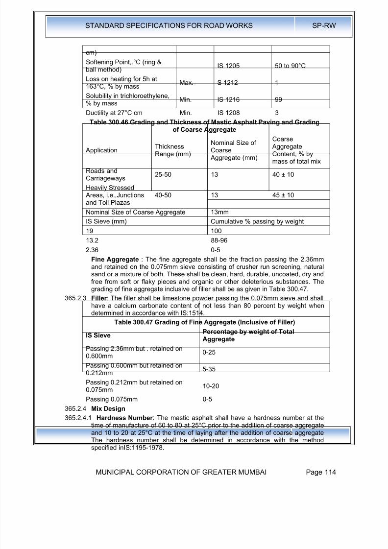
8/19/2019 MCGM Road Spec Volume -II
http://slidepdf.com/reader/full/mcgm-road-spec-volume-ii 118/176
STANDARD SPECIFICATIONS FOR ROAD WORKS SP-RW
MUNICIPAL CORPORATION OF GREATER MUMBAI Page 114
cm)
Softening Point,.°C (ring &ball method)
IS 1205 50 to 90°C
Loss on heating for 5h at
163°C, % by massMax. S 1212 1
Solubility in trichloroethylene,% by mass
Min. IS 1216 99
Ductility at 27°C cm Min. IS 1208 3
Table 300.46 Grading and Thickness of Mastic Asphalt Paving and Gradingof Coarse Aggregate
ApplicationThicknessRange (mm)
Nominal Size ofCoarse Aggregate (mm)
Coarse AggregateContent, % bymass of total mix
Roads andCarriageways 25-50 13 40 ± 10
Heavily Stressed Areas, i.e.,Junctionsand Toll Plazas
40-50 13 45 ± 10
Nominal Size of Coarse Aggregate
IS Sieve (mm)
13mm
Cumulative % passing by weight
19 100
13.2 88-96
2.36 0-5
Fine Aggregate : The fine aggregate shall be the fraction passing the 2.36mmand retained on the 0.075mm sieve consisting of crusher run screening, naturalsand or a mixture of both. These shall be clean, hard, durable, uncoated, dry andfree from soft or flaky pieces and organic or other deleterious substances. Thegrading of fine aggregate inclusive of filler shall be as given in Table 300.47.
365.2.3 Filler : The filler shall be limestone powder passing the 0.075mm sieve and shallhave a calcium carbonate content of not less than 80 percent by weight whendetermined in accordance with IS:1514.
Table 300.47 Grading of Fine Aggregate (Inclusive of Filler)
IS SievePercentage by weight of TotalAggregate
Passing 2.36mm but . retained on0.600mm
0-25
Passing 0.600mm but retained on0.212mm
5-35
Passing 0.212mm but retained on0.075mm
10-20
Passing 0.075mm 0-5
365.2.4 Mix Design
365.2.4.1 Hardness Number : The mastic asphalt shall have a hardness number at thetime of manufacture of 60 to 80 at 25°C prior to the addition of coarse aggregate
and 10 to 20 at 25°C at the time of laying after the addition of coarse aggregateThe hardness number shall be determined in accordance with the methodspecified inIS:1195-1978.

8/19/2019 MCGM Road Spec Volume -II
http://slidepdf.com/reader/full/mcgm-road-spec-volume-ii 119/176
STANDARD SPECIFICATIONS FOR ROAD WORKS SP-RW
MUNICIPAL CORPORATION OF GREATER MUMBAI Page 115
365.2.5 Binder Content : The binder content shall be so fixed as to achieve therequirements of the mixture specified in Clause 365.2.5.1 and shall be in therange of 14 to 17 per cent by weight of total mixture as indicated in Table 300.47.
365.2.6 Job Mix Formula: The Contractor shall inform the Engineer in writing at least 1
month before the start of the work of the job mix formula proposed to be used byhim for the work, indicating the source and location of all materials, proportions ofall materials such as binder and aggregates, single definite percentage passingeach sieve for the mixed aggregate and results of the tests recommended in thevarious Tables and Clauses of this Specification.
365.3 Construction Operations
365.3.1 Weather and Seasonal Limitations: The provisions of Clause 318 shall apply,except that laying shall not be carried out when the air temperature at the surfaceon which the Mastic Asphalt is to be laid is below 10°C.
365.3.2 Preparation of the base : The base on which mastic asphalt is to be laid shallbe prepared, shaped and conditioned to the profile required, in accordance withClause 318 or 600 as 'appropriate or as directed by the Engineer. In the case ofa cement concrete base, the surface shall be thoroughly power brushed cleanand free of dust and other deleterious matter. Under no circumstances shallmastic asphalt be spread on a base containing a binder which might soften underhigh application temperatures. If such material exists, the same shall be cut outand repaired before the mastic asphalt is laid.
365.3.3 Tack Coat: A tack coat in accordance with Clause 314 shall be applied on thebase or as directed by the Engineer.
365.3.4 Preparation of Mastic Asphalt : Penetration of mastic asphalt consists of twostages. The first stage shall be mixing of filler and fine aggregates and thenheating the mixture· to a temperature of 170°C to 210°C. Required quantity ofbitumen shall be heated to 170°C to 180°C and added to the heated aggregated.
They shall be mixed and cooked in an approved type of mechanically agitatedmastic cooker for some tim'e till the materials are thoroughly mixed. Initially thefiller along is to be heated in the cooker for an hour and then half the quantity ofbinder is added. After heating and mixing for some time, the fine aggregates andthe balance of binder are to be added and further cooked for about one hour.The second stage is incorporation of coarse aggregates and cooling the mixturefor a total period of 3 hours. During cooking and mixing, care shall be taken toensure that the contents in the cooker are at no time heated to a temperatureexceeding 210°C.
Where the material is not required for immediate use it shall be cast . into blocksconsisting of filler, fine aggregates and binder, but without the addition of coarse
aggregate, weighing about 25 Kgs each. Before . use, these blocks shall bereheated to a temperature of not less than 175°C and not more than 210°C,thoroughly incorporated with the requisite quantity of coarse aggregates andmixed continuously. Mixing shall be continued until laying operations are,completed so as to maintain the coarse aggregates in suspension. At no stageduring the process of mixing shall be the temperature exceeds 210°C.
The mastic asphalt blocks (without coarse aggregate) shall show on analysis acomposition within the limits as given in Table 300.47.
The mixture shall be transported to the laying site in a towed mixer transporterhaving arrangement for stirring and keeping the mixture hot duringtransportation.
365.3.5 Spreading: The mastic asphalt shall be laid, normally in one coat, at atemperature between 175°C and 210°C and spread uniformly by hand using
8/19/2019 MCGM Road Spec Volume -II
http://slidepdf.com/reader/full/mcgm-road-spec-volume-ii 120/176
STANDARD SPECIFICATIONS FOR ROAD WORKS SP-RW
MUNICIPAL CORPORATION OF GREATER MUMBAI Page 116
wooden floats or by machine on the prepared and regulated surface. Thethickness of the mastic asphalt and the percentage of added coarse aggregateshall be in accordance with Table 300. 46 or as specified by the Engineer. Wherenecessary, battens of the requisite dimensions should be employed. Any blowholes that appear in the surface shall be punctured while the material is hot, andthe surface made good by further floating.
365.3.6 Joints: All construction joints shall be properly and truly made. These joints shallbe made by warming existing mastic asphalt by the application of an excessquantity of the hot mastic asphalt mixture which afterwards shall be trimmed toleave it flush with the surfaces on either side.
365.3.7 Surface Finish: The mastic asphalt surface can have poor skid resistance toskidding, the mastic asphalt after spreading, while still hot and in a plasticcondition shall be covered with a layer of stone aggregate. This aggregate shallbe 13.2mm size (passing the 19.0mm sieve and retained on the 9.5mm sieve) or9.5mm size (passing the 13.2mm sieve and retained on the 6.7mm sieve)subject to the approval of the Engineer. Hard stone chips, complying with the
quality requirements of Table 300.44 ,shall be pre-coated with bitumen at therate of 2 ± 0.4% of S-65 penetration grade. The addition of 2% of filler complyingwith Table 300.47 may be required to enable this quantity of binder to be heldwithout draining. The chips shall then be applied at the rate of 0.005 Cu. M. per10 Sq. M. and rolled or otherwise pressed into the surface of the mastic layerwhen the temperature of the mastic asphalt Is not less than 100°C.
365.3.8 Opening to Traffic: Traffic may be allowed after completion of the work whenthe mastic asphalt temperature at the mid-depth of the completed layer hascooled to the daytime maximum ambient temperature.
365.3.9 Surface Finish and Quality Control of Work: The surface finish of thecompleted construction shall conform to the requirements of Clause 620.
365.3.10 For control of the quality of materials supplied and the works carried out, therelevant provisions of Section 600shall apply.
The surface of the mastic asphalt,' tested with a straight edge 3.0m long, placedparallel to the centre line of the carriageway, shall have no depression greaterthan 7mm. the same limit shall also apply to the transverse profile when testedwith a camber template.
365.3.11 Arrangements for Traffic : During the period of construction, arrangements fortraffic shall be made in accordance with the provisions of Clause 30.
365.3.12 Measurement for Payment: Mastic asphalt shall be measured as finished· workin square metres at a specified thickness, or by weight in tones as stated in theContract.
365.3.13 Rate : The contract unit rate for mastic asphalt shall be payment in full forcarrying out the required operations including full compensation for allcomponents listed under Clause 318.11 (i) to (ix).

8/19/2019 MCGM Road Spec Volume -II
http://slidepdf.com/reader/full/mcgm-road-spec-volume-ii 121/176
STANDARD SPECIFICATIONS FOR ROAD WORKS SP-RW
MUNICIPAL CORPORATION OF GREATER MUMBAI Page 117
370.0 Seal Coat
370.1 Scope : This work shall consist of the application of a seal coat for sealing thevoids in a bituminous surface laid to the specified levels, grade and cross fall
(camber).Seal coat shall be of either of the two types specified below:
Liquid seal coat comprising of an application of a layer of bituminous binderfollowed by a cover of stone chips.
370.2 Binder : The requirements of Clauses 361.2.2.1 shall apply.
The quantity of bitumen per 10 square metres, shall be 9.8 Kg. for Type A sealcoat. Where bituminous' emulsion is used as a binder the quantities for Type Aseal coats shall be 15 Kg per 10 square meters rapid setting (clause 4.2.2 ofIRC:14-2004). .
370.2.1 Stone Chips for Type A Seal Coat: The stone chips shall consist of angularfragments of clean, hard, tough and durable rock of uniform quality throughout.They should be free of soft or disintegrated stone, organic or other deleteriousmatter. Stone chips shall be of 6.7mm size defined as 100 per cent passingthrough 11.2mm sieve and retained on 2.36mm sieve the quantity used forspreading shall be 0.09 cubic metre per 10 square metre area. The chips shallsatisfy the quality requirements in Table300.22 except that the upper limit forwater absorption value shall be 1 per cent.
370.3 Construction Operations:
370.3.1 Weather and Seasonal Limitations : The requirements of Clause 318.6.1 shallapply.
370.3.2 Preparation of Surface : The seal coat shall be applied immediately after layingthe bituminous course which is required to be sealed. Before application of sealcoat materials, the surface shall be cleaned free of any dust or other extraneousmatter.
370.3.3 Construction of Type A Seal Coat : Bitumen shall be heated to 150°C-163°Cand sprayed at the rate specified on the dry surface in a uniform manner with aself-propelled mechanical sprayer as described in the Manual for Constructionand Supervision of Bituminous Works.
Immediately after the application of binder, stone chips, which shall be clean anddry, shall be spread uniformly at the rate specified on the surface preferably bymeans of a self-propelled or towed mechanical grit spreader so as to cover thesurface completely. If necessary, the surface shall be brushed to ensure uniformspread of chips.
Immediately after the application of the cover material, the entire surface shall berolled with a 8-10 tonne smooth wheeled steel roller, 8-10 tonne static weightvibratory roller, or other equipment approved by the Engineer after laying trials ifrequired. Rolling shall commence at the edge~ and progress towards the centreexcept in super elevated and unidirectional cambered portions where it shallproceed from the lower edge to the higher edge. Each pass of the roller shalluniformly overlap not less than one-third of the track made in the preceding pass.While rolling is in progress, additional chips shall be spread by hand in necessaryquantities required to make up irregularities. Rolling shall continue until allaggregate particles are firmly embedded in the binder and present a uniformclosed surface.
370.3.4 Opening to Traffic : In the case of Type A Seal Coat, traffic shall not bepermitted to run on any newly sealed area until the following day. In special
8/19/2019 MCGM Road Spec Volume -II
http://slidepdf.com/reader/full/mcgm-road-spec-volume-ii 122/176
STANDARD SPECIFICATIONS FOR ROAD WORKS SP-RW
MUNICIPAL CORPORATION OF GREATER MUMBAI Page 118
circumstances, however, the Engineer may open the road to traffic immediatelyafter rolling, but in such cases, traffic speed shall be rigorously limited to 16 Km.per hour until the following day.
370.3.5 Surface Finish and Quality Control of Work : The surface finish of construction
shall conform to the requirements of Clause 610For -control on the quality of materials supplied and the works carried out, therelevant provisions of Section 600 shall apply.
370.3.6 Arrangement for Traffic: During the period of construction, arrangements fortraffic shall be made in accordance with the provisions of Clause 30.
370.3.7 Measurement for Payment: Seal Coat shall be measured as finished work, overthe area specified to be covered, in square metre at the thickness specified in theContract.
370.3.8 Rate: The contract unit rate for seal coat shall be payment in full for carrying outthe' required operations including full compensation for all components listed inClause 318.11.
375.0 Slurry Seal375.1 Scope : Slurry seals are mixtures of fine aggregate, Portland cement filler,
bitumen emulsion and additional water. When freshly mixed, they have a thickconsistency and can be spread to a thickness of 1.5 - 5 mm. They may be usedto seal cracks, arrest fretting and fill voids and minor depressions, to provide amore even riding surface or a base for further treatment; they may also be usedon top of a single coat surface dressing.
375.2 Materials : The materials for slurry seal immediately prior to mixing shall conformto the following requirements :
375.2.1 Emulsified Bitumen : The emulsified bitumen shall be a cationic rapid settingtype as approved by the Engineer, conforming to the requirements of IS:8887 ..
Where special mobile mixing machines are available, Class .A4* rapid setting .orClass K3* road emulsions to BS~ 434: Part I should be used, to obtain very earlyresistance to traffic and rain. Generally, emulsion for slurry seal should becapable of producing a slurry that will develop early resistance to traffic and rainand is sufficiently stable to permit mixing with the specified aggregate, withoutbreaking during the mixing and laying processes. If approved by the Engineer, aslow setting emulsion may be used. Guidance on selection of an appropriategrade of emulsion is given in the Manual for Construction and Supervision ofBituminous Works.
375.2.2 Water : Water shall be of such quality that the bitumen will not separate from theemulsion before the slurry seal is in place.
The pH of the water must lie in the range 4 to 7, and if the total dissolved solidsin the water amount to more than 500ppm, the Engineer may reject it, or orderthe Contractor to conduct a trial emulsion mix to demonstrate that it does notcause early separation.
375.2.3 Aggregate : The aggregate shall be crushed rock, or slag and may be blended,if required, with clean, sharp, naturally occurring sand free from soft pieces andorganic and other deleterious substances to produce a grading as given in Table300.47 A. The aggregates shall meet the requirements of the film stripping test(IS:6241). and a suitable amount and type of anti-stripping agent added, as maybe needed (details given in Appendix 5).
375.2.4 Additives: It is usual to use ordinary Portland cement, hydrated lime or otheradditives to control consistency, mix segregation and setting rate. The proportionof the additive should not normally exceed 2 per cent by weight of dryaggregates.

8/19/2019 MCGM Road Spec Volume -II
http://slidepdf.com/reader/full/mcgm-road-spec-volume-ii 123/176
STANDARD SPECIFICATIONS FOR ROAD WORKS SP-RW
MUNICIPAL CORPORATION OF GREATER MUMBAI Page 119
375.3 Mixture Design : A range of residual binder contents for each aggregate gradingis given in Table 300.47 A. The optimum mixture design for the aggregateadditive, water and bitumen emulsion mixture should be determined inaccordance with ASTM D 3910.
375.4 Construction Operations:375.4.1 Weather and Seasonal Limitations: Clause 318.4.1 shall apply.
Table 300.47 Aggregate Grading, Binder Content and Approximate CoverageRate
Sieve Size (mm)
Percentage by Mass PassingFinished Thickness of Sealing
5mm 3mm 1.5mm
9.5 100 - -
4.75 90-100 100 -
3.35 - 80-100 100
2.36 65-90 75-100 95-1001.18 45-70 55-90 70-95
0.600 30-50 35-70 55-75
0.300 18-30 20-45 30-50
0.150 10-21 10-25 10-30
0.075 5-15 5-15 5-15
Quantity of residual binder, percentage bymass of aggregate
7.5-13.5 10-16 12-20
Approximate coverage rate (Kg./m2) 8-15 4-6 2-4
375.4.2 Surface Preparation : Any necessary remedial work to the road surface andstructure shall be completed either prior to or as part of the Contract and agreedas acceptable by the Engineer, according to the provisions of Clause 318.
Before slurry seal is applied, street furniture and, where directed by the Engineer,road markings, shall be masked using self-adhesive masking material or othermaterial firmly secured against the passage of the spreader box or the tools usedfor hand laying. Any packed mud or other deposits on the surface shall beremoved, all organic growth shall be removed by suitable means, and thesurface shall be swept free of all loose material.
375.4.3 Tack Coat : If required by the Engineer, a tack coat may be applied prior to theslurry seal, with or without grit or chips, in order to seal the existing substrata and
enhance the bond to the existing road surface. Unless otherwise agreed by theEngineer, the rate of spread of tack coat shall be 0.15 to 0.30 Iitres I m2 forbituminous surfa.ces and .04 to 0.6 litres I m2 for concrete surfaces.
375.4.4 Mixing and Transportation of Mixture : Mixing (and laying) techniques varyaccording to the type of emulsion used. For class A4 rapid setting and K3emulsions, only special mobile mixing machines should be used. These carrysupplies of aggregate, emulsion, water and filler (e.g. ordinary Portland cementor hydrated lime) and are fitted with metering devices to feed the ingredients intheir correct proportions to a mixer fitted to the rear of the machine. From themixer the slurry is fed into the screed box towed by the machine.
For all other emulsions, mixing may be by hand, concrete mixer or other mixer
which effectively coats the aggregate uniformly and produces a slurry seal ofsuitable consistency for satisfactory laying. For large areas, a bulk transitconcrete mixer may be used into which the ingredients (including water) are
8/19/2019 MCGM Road Spec Volume -II
http://slidepdf.com/reader/full/mcgm-road-spec-volume-ii 124/176

8/19/2019 MCGM Road Spec Volume -II
http://slidepdf.com/reader/full/mcgm-road-spec-volume-ii 125/176
STANDARD SPECIFICATIONS FOR ROAD WORKS SP-RW
MUNICIPAL CORPORATION OF GREATER MUMBAI Page 121
Further operations to remove subsequently loosened aggregate shall be carriedout over the next 48 hours. The areas treated and adjacent side roads, footwaysand paved areas shall be kept substantially free of loose aggregate for a periodof 30 days after completion of the work. 375.6 Surface Finish and Quality Controlof Work : Generally, the surface finish of the completed construction shallconform to the requirements supplied and the works carried out, the relevantprovisions of Section 600 shall apply.
In addition, the finished slurry shall have a uniform surface texture throughout thework, without variations of texture within the lane width, or from lane to lane, dueto segregation of aggregates, or due to variations in the emulsion / water contentof the mixture.
The finished surface shall be free from blow holes and surface irregularities inexcess of 3mm beneath a 1 metre straight edge due to scraping, scabbing,dragging, droppings, excess overlapping or badly aligned longitudinal ortransverse joints, damage by rain or frost, or other defects which remain 24hours after laying. 375.7 Arrangements for Traffic : During the period of
construction, arrangements for traffic shall be made in accordance with theprovisions of Clause 30.
375.8 Measurements for Payment : Slurry seal shall be measured as finished work asspecified, in square metres.
375.9 Rates: The contract unit rate for slurry seal shall be payment in full for carryingout the required operations including full compensation for all components listedin Clause 318.11 (i) to (xi).
380.0 Recycling of Bituminous Pavement
380.2 Scope : This Clause of the Specifications covers the recycling of existingbituminous pavement materials to upgrade an existing bituminous pavementwhich has served its first-intended purpose. The work shall be performed on
such widths and lengths as may be directed by the Engineer and may consist ofpavement removal, stockpiling of materials from the old pavement, addition ofnew bitumen and untreated aggregate in the requisite proportions, mixing,spreading and compaction of the blended materials.
Recycling processes can be categorised into in-situ recycling (where processingtakes placed on site), and central plant recycling (where reclaimed material isprocessed off site). The processes can be further sub-divided into hot and coldprocesses. This Specification covers the hot process only. However, reclaimedaggregated from cold in-situ recycling can be used in the Bituminous Cold Mixprocess specified in Clause 317, subject to the resultant mixes achieving thespecified standards.
380.3 Reclaimed Bituminous Materials for Central Plant Recycling:380.3.4 Proportion of reclaimed materials less than 10 per cent : If not more than 10% of
reclaimed bituminous material is to be used in the production of bituminousmacadam or dense graded bituminous base or binder course material, thenClauses 380.2.2 to 380,2.9 do not apply. However:
i) all reclaimed bituminous material shall be pre-treated before use such thatthe material is homogeneously mixed and the maximum particle size ofreclaimed materials does not exceed 40mm.
ii) the mixed material shall comply with the requirements of Clauses 351 or 354as appropriate.
380.2.2 Proportions of reclaimed materials greater than 10 per cent : Reclaimed
bituminous material of an amount greater than 10 per cent, may be used in theproduction of bituminous macadam and dense graded bituminous base and

8/19/2019 MCGM Road Spec Volume -II
http://slidepdf.com/reader/full/mcgm-road-spec-volume-ii 126/176
STANDARD SPECIFICATIONS FOR ROAD WORKS SP-RW
MUNICIPAL CORPORATION OF GREATER MUMBAI Page 122
binder course material, subject to the requirements of Clauses 380.2.3 to 380.2.9and subject to the satisfactory completion of full trial investigations in respect ofall related materials, layer thickness, machine operations and finished works on acase-by-case basis entirely at the contractors cost and subject to the approval ofthe Engineer. For estimating purposes, a maximum amount not greater than 30per cent reclaimed bituminous material should be assumed.
380.2.3 Materials for Recycled Pavement: The recycled materials shall be a blend ofreclaimed and new materials proportioned to achieve a paving mixture with thespecified engineering properties. The reclaimed materials shall be tested andevaluated to find the optimum blend meeting the mixture requirements. Suchtesting and evaluation shall be carried out on representative samples, eithercores sampled from the carriageway or samples taken from stockpiles inaccordance with current practice. The sampling frequency should be sufficient todetermine how consistent the reclaimed material is and to provide representativesamples for composition analysis and measurement of properties of recoveredbinder. As an absolute minimum, one sample to represent 500n:t0f lane
carriageway shall be taken.380.2.4 Bitumen Extraction: The procedure described in ASTM 0-2172 shall be used to
quantitatively separate aggregate and bitumen from any representative sampleof reclaimed bituminous pavement.
380.2.5 Aggregate Evaluation: Mechanical sieve analysis (lS: 2386, Part-I, wet . sievingmethod) shall be performed on the aggregate portion of the reclaimed bituminouspavement sample to determine the grading. It is essential that the reclaimedmaterials to be recycled are consistent, as variable materials will cause problemswith the control of quality and impede the efficiency of the recycling operation.Suitable sources of consistent material of sufficient quantity for the scheme beingconsidered need to be identified either in existing pavements, from stockpiled
planings of known origin or from another suitable source, before a decision canbe made on the optimum percentage of reclaimed material.
After selecting the proportion of reclaimed materials to be recycled, the gradingof the mixture may need adjustment, to meet Specification requirements, by theaddition of selected aggregate sizes. Evaluation of bitumen : When the amountof reclaimed bituminous material to be used in the mixture exceeds 10%, thepenetration value of the recovered binder from the reclaimed bituminousmaterial, before mixing, shall exceed 15 pen, after recovery of binder inaccordance with the requirements of IS 2000 : Part-397, when tested inaccordance with IS:1203. Provided the above requirement is met, hardening ofthe old binder, during the original mixing process or through ageing, can becompensated for by adding a softer bitumen, to obtain the appropriate final grade
of binder.The determination of the type and amount of binder required to be added in thefinal mix is essentially a trial and error procedure.
After mixing with recycled materials, the binder recovered from the mixture shallhave a recovered penetration value not less than the value specified in Table300.48.
Table 300.48 Minimum Recovered Binder Penetration of Recycled Mixture
Specified Grade of Binder(Penetration)
Minimum Recovered PenetrationValue of Binder after Mixing
45 27
65 3990 54

8/19/2019 MCGM Road Spec Volume -II
http://slidepdf.com/reader/full/mcgm-road-spec-volume-ii 127/176
STANDARD SPECIFICATIONS FOR ROAD WORKS SP-RW
MUNICIPAL CORPORATION OF GREATER MUMBAI Page 123
380.2.7 Rejuvenators : The use of rejuvenators, and a test to measure theireffectiveness, is described in Clause 380.6.3.
380.2.8 Untreated Aggregate: If necessary, fresh untreated aggregate shall be added tothe reclaimed bituminous pavement to produce a mix with the desired grading.
The aggregate shall be checked for quality requirements in accordance withTable 300.22 as appropriate. Reclaimed aggregate, if any, or any aggregatenormally used for the desired bituminous mixture, or both, may be used for thispurpose.
380.2.9 Combined Aggregate Grading : The blend of reclaimed and new aggregateshall meet the grading criteria specified in the relevant parts of Clause 351 or354, as appropriate and as approved by the Engineer. The blend of aggregatesshall be checked for resistance to stripping as specified in Tables 300.22 asappropriate.
380.3 Mixture Design : The combined aggregate grading and binder content shallcomply with the relevant tables in Clauses 351 or 354. For dense gradedbituminous mixtures, the mixture design shall also comply with the requirements
of Table 300.30.
380.4 Reclaiming Old Pavement Materials : The removal of pavement materials tothe required depth shall be accomplished either at ambient temperature (coldprocess) or at an elevated temperature (hot process). as approved by theEngineer.
380.4.1 Cold Removal Process: In the cold process, the ripping and crushingoperations shall be carried out using scarifiers, grid rollers, or rippers or by anyother means as directed by the Engineer. The removed materials shall be loadedand hauled for crushing to the' required size as directed by the Engineer. Alternatively, cold miling or planing machines can be used to reclaim bituminouspavement to controlled depths. After the bituminous layers are removed, any
remaining aggregate materials that are to be incorporated in the recycled hotmixture shall be scarified and removed. When the pavement material removal iscompleted, any drainage deficiencies shall be corrected. After that, the base Isub-base as the case may be shall be cut, graded and compacted to the requiredprofile and density.
380.4.2 Hot Removal Process : In this process, the road surface shall be heated, by anysuitable means approved by the Engineer, before scarification. A self-propelledplant shall be used, and a milling drum that follows the planer removes theheated soft bituminous layer. The depth, width and speed of travel shall beadjusted to suit specified requirements as directed by the Engineer. During theheating process, the surface temperature of the road shall not exceed 200°C formore than 5 minutes.
380.4.3 Stockpiling : In the cold process, the reclaimed bituminous pavement materialshall be stockpiled with the height of stockpiles not exceeding 3m. The reclaimeduntreated aggregate base I sub-base material shall be stockpiled in the samemanner as new aggregate. The number and location of stockpiles shall becarefully planned for efficient operation of the hot-mix plant.
380.5 Mixing and Laying: Generally, the requirements of Clauses 351 or 354, asappropriate, shall apply.
380.6 In Situ Recycling - The Remix and Repave Processes : These processes aresuitable for the production of· bituminous concrete wearing course in accordancewith the provisions of Clause 364.
380.6.1 Scope : In the process of repaving, the existing surface is preheated andscarified but the scarified material is not removed. A layer of fresh bituminous

8/19/2019 MCGM Road Spec Volume -II
http://slidepdf.com/reader/full/mcgm-road-spec-volume-ii 128/176

8/19/2019 MCGM Road Spec Volume -II
http://slidepdf.com/reader/full/mcgm-road-spec-volume-ii 129/176

8/19/2019 MCGM Road Spec Volume -II
http://slidepdf.com/reader/full/mcgm-road-spec-volume-ii 130/176
STANDARD SPECIFICATIONS FOR ROAD WORKS SP-RW
MUNICIPAL CORPORATION OF GREATER MUMBAI Page 126
380.10 Measurement for Payment : The recycled pavement work shall be payment infull for carrying out the required operations including full compensation for allitems as Clause 318.11 (i) to (xi).
8/19/2019 MCGM Road Spec Volume -II
http://slidepdf.com/reader/full/mcgm-road-spec-volume-ii 131/176
STANDARD SPECIFICATIONS FOR ROAD WORKS SP-RW
MUNICIPAL CORPORATION OF GREATER MUMBAI Page 127
400.0 Cement Concrete
410.0 Structural Concrete :
Structural Concrete shall be as per IS:456-2000 : Clause-6.
410.1 Concrete Making Materials 410.1.1 Cement: Ordinary Portland Cement conforming to IS:269, IS:8112, IS:12269;
Portland Slag Cement conforming to IS:455, Portland Pozzolana Cement as perIS:1489 (Part-1)
410.1.2 Mineral Admixtures: Fly Ash conforming to Grade-I of IS:3812
410.1.3 Aggregates: Aggregates shall comply with requirements of IS:383
The size of Aggregate : The nominal maximum size of coarse aggregate shouldbe 20mm.
410.1.4 Water: Water as per Clause 5.4 of IS:456 2000.
410.1.5 Admixtures: Admixtures shall comply with IS:9103
410.1.6 Reinforcement: Reinforcement shall be mild steel and medium tensile steel barsconforming to IS:432 (Part-1), high strength deformed steel bars conforming to15:1786
410.2 Storage of Materials : Storage of Materials shall be as per IS:4082
410.3 Production of Concrete as per Clause 10 of IS:456.
425.0 Ready Mix Concrete
The contractor shall procure RMC from the RMC plant approved by MCGM only.The RMC prepared and transported will be as per relevant IS:4926. Thefollowing information on the performance of Ready Mix Concrete supplied by theplant shall be obtained.
425.1 Following past data regarding raw materials and equipment deployed shall be
obtained from RMC manufacturer .Proforma Table 400.1
Cement Grade Source Type IS
Strength (N/mm2) 3 days 7 days 28 days 6 months 1 Year
Average
Standard
Deviation
Initial SettingTime
Final SettingTime
425.2 Coarse Aggregate
Size Source Grading Zone
Proforma Table 400.2
Characteristic Property Average ValueStandardDeviation
Remarks
Fineness Modules
Specific GravityBulk Density

8/19/2019 MCGM Road Spec Volume -II
http://slidepdf.com/reader/full/mcgm-road-spec-volume-ii 132/176
STANDARD SPECIFICATIONS FOR ROAD WORKS SP-RW
MUNICIPAL CORPORATION OF GREATER MUMBAI Page 128
Crushing Value
Impact Value
Abrasion Value
Soundness (averageloss after 5 cycles)
Water absorption
Deleterious Materials
Surface Water
425.3 Fine Aggregate
Source Grading Zone
Proforma Table 400.3
Characteristic Property Average ValueStandard
Deviation
Remarks
Fineness Modules
Specific Gravity
Bulk Density
Crushing Value
Impact Value·
Abrasion Value
Soundness (average lossafter 5 cycles)
Water absorption
Deleterious Materials
Surface Water
425.4 Water
Source
Proforma Table 400.4
Property Average Standard Deviation
p. H Value
% of strength of cubes
prepared with boiled
watersolids in water -
Organic
Inorganic
Sulphates (S03)
Suspended Matters
425.5 Mineral Admixtures
Source
Proforma Table 400.5
Property Average Standard DeviationFineness Modulus
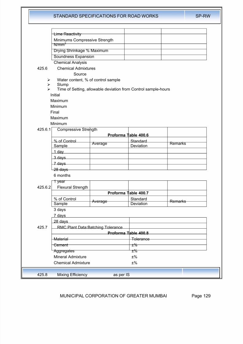
8/19/2019 MCGM Road Spec Volume -II
http://slidepdf.com/reader/full/mcgm-road-spec-volume-ii 133/176
STANDARD SPECIFICATIONS FOR ROAD WORKS SP-RW
MUNICIPAL CORPORATION OF GREATER MUMBAI Page 129
Lime Reactivity
Minimums Compressive StrengthN/mm2
Drying Shrinkage % Maximum
Soundness Expansion
Chemical Analysis
425.6 Chemical Admixtures
Source
Water content, % of control sample Slump Time of Setting, allowable deviation from Control sample-hours
Initial
Maximum
Minimum
Final
Maximum
Minimum
425.6.1 Compressive Strength
Proforma Table 400.6
% of ControlSample
AverageStandardDeviation
Remarks
1 day
3 days
7 days28 days
6 months
1 year
425.6.2 Flexural Strength
Proforma Table 400.7
% of ControlSample
AverageStandardDeviation
Remarks
3 days
7 days
28 days
425.7 RMC Plant Data:Batching Tolerance
Proforma Table 400.8
Material Tolerance
Cement ±%
Aggregates ±%
Mineral Admixture ±%
Chemical Admixture ±%
425.8 Mixing Efficiency as per IS
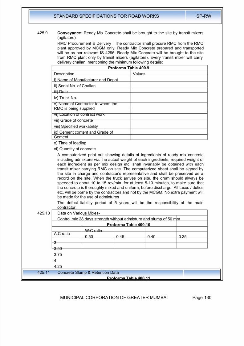
8/19/2019 MCGM Road Spec Volume -II
http://slidepdf.com/reader/full/mcgm-road-spec-volume-ii 134/176
STANDARD SPECIFICATIONS FOR ROAD WORKS SP-RW
MUNICIPAL CORPORATION OF GREATER MUMBAI Page 130
425.9 Conveyance: Ready Mix Concrete shall be brought to the site by transit mixers(agitators).
RMC Procurement & Delivery : The contractor shall procure RMC from the RMCplant approved by MCGM only. Ready Mix Concrete prepared and transported
will be as per relevant IS 4296. Ready Mix Concrete will be brought to the sitefrom RMC plant only by transit mixers (agitators). Every transit mixer will carrydelivery challan, mentioning the minimum following details:
Proforma Table 400.9
Description Values
i) Name of Manufacturer and Depot
ii) Serial No. of Challan
iii) Date
iv) Truck No.
v) Name of Contractor to whom the
RMC is being suppliedvi) Location of contract work
vii) Grade of concrete
viii) Specified workability
ix) Cement content and Grade ofCement
x) Time of loading
xi) Quantity of concrete
A computerized print out showing details of ingredients of ready mix concreteincluding admixture viz. the actual weight of each ingredients, required weight of
each ingredient as per mix design etc. shall invariably be obtained with eachtransit mixer carrying RMC on site. The computerized sheet shall be signed bythe site in charge and contractor's representative and shall be preserved as arecord on the site. When the truck arrives on site, the drum should always bespeeded to about 10 to 15 rev/min. for at least 5-10 minutes, to make sure thatthe concrete is thoroughly mixed and uniform, before discharge. All taxes / dutiesetc. will be borne by the contractors and not by the MCGM. No extra payment willbe made for the use of admixtures
The defect liability period of 5 years will be the responsibility of the maincontractor.
425.10 Data on Various Mixes-
Control mix 28 days strength without admixture and slump of 50 mmProforma Table 400.10
A:C ratioW:C ratio
0.50 0.45 0.40 0.35
3
3.50
3.75
4
4.25
425.11 Concrete Slump & Retention DataProforma Table 400.11
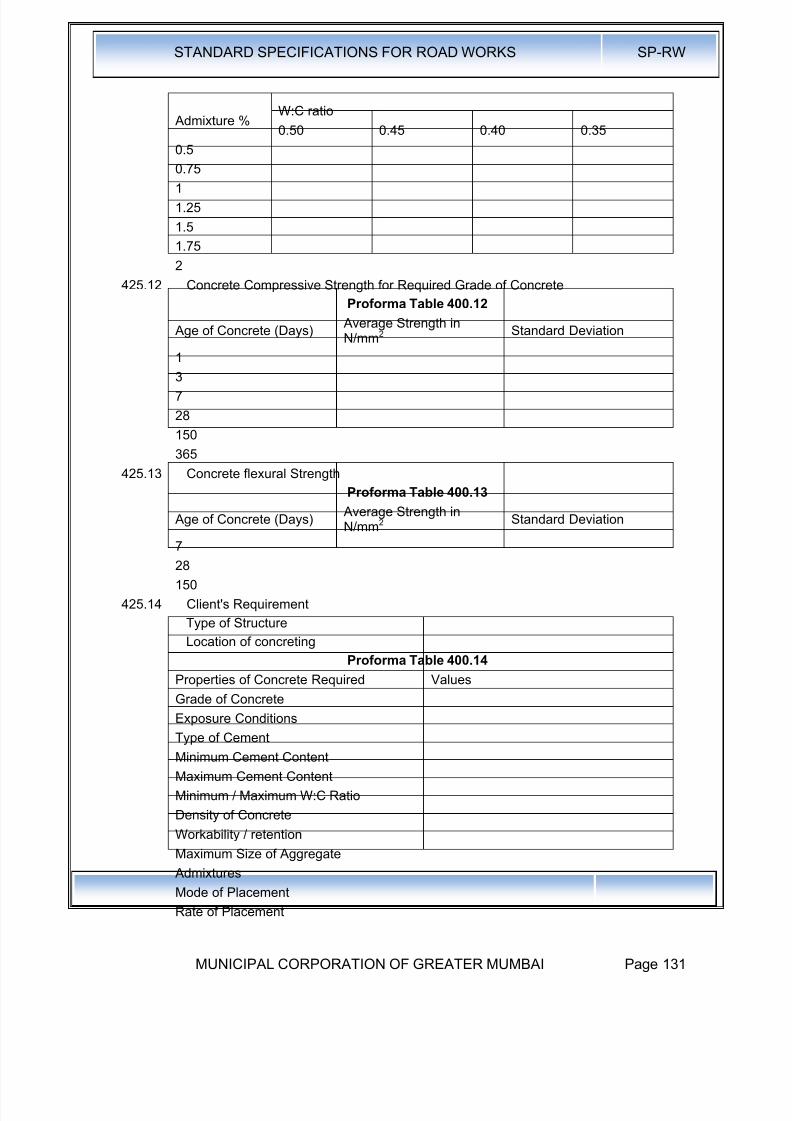
8/19/2019 MCGM Road Spec Volume -II
http://slidepdf.com/reader/full/mcgm-road-spec-volume-ii 135/176
STANDARD SPECIFICATIONS FOR ROAD WORKS SP-RW
MUNICIPAL CORPORATION OF GREATER MUMBAI Page 131
Admixture %W:C ratio
0.50 0.45 0.40 0.35
0.5
0.75
1
1.25
1.5
1.75
2
425.12 Concrete Compressive Strength for Required Grade of Concrete
Proforma Table 400.12
Age of Concrete (Days) Average Strength inN/mm2
Standard Deviation
13
7
28
150
365
425.13 Concrete flexural Strength
Proforma Table 400.13
Age of Concrete (Days) Average Strength in
N/mm
2
Standard Deviation
7
28
150
425.14 Client's Requirement
Type of Structure
Location of concreting
Proforma Table 400.14
Properties of Concrete Required Values
Grade of Concrete
Exposure Conditions
Type of Cement
Minimum Cement Content
Maximum Cement Content
Minimum / Maximum W:C Ratio
Density of Concrete
Workability / retention
Maximum Size of Aggregate
Admixtures
Mode of PlacementRate of Placement
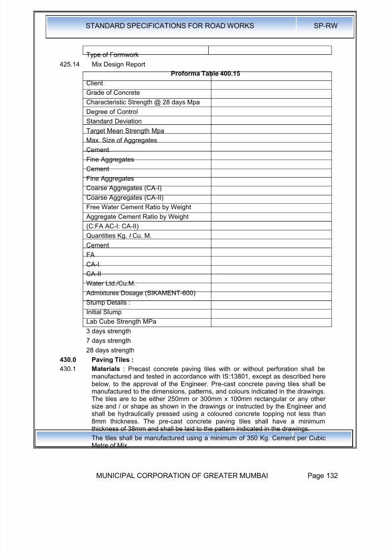
8/19/2019 MCGM Road Spec Volume -II
http://slidepdf.com/reader/full/mcgm-road-spec-volume-ii 136/176
STANDARD SPECIFICATIONS FOR ROAD WORKS SP-RW
MUNICIPAL CORPORATION OF GREATER MUMBAI Page 132
Type of Formwork
425.14 Mix Design Report
Proforma Table 400.15
Client
Grade of Concrete
Characteristic Strength @ 28 days Mpa
Degree of Control
Standard Deviation
Target Mean Strength Mpa
Max. Size of Aggregates
Cement
Fine Aggregates
Cement
Fine Aggregates
Coarse Aggregates (CA-I)
Coarse Aggregates (CA-II)
Free Water Cement Ratio by Weight
Aggregate Cement Ratio by Weight
(C:FA AC-I: CA-II)
Quantities Kg. I Cu. M.
Cement
FA
CA-ICA-II
Water Ltd./Cu.M.
Admixtures Dosage (SIKAMENT-600)
Stump Details :
Initial Slump
Lab Cube Strength MPa
3 days strength
7 days strength
28 days strength430.0 Paving Tiles :
430.1 Materials : Precast concrete paving tiles with or without perforation shall bemanufactured and tested in accordance with IS:13801, except as described herebelow, to the approval of the Engineer. Pre-cast concrete paving tiles shall bemanufactured to the dimensions, patterns, and colours indicated in the drawings.The tiles are to be either 250mm or 300mm x 100mm rectangular or any othersize and / or shape as shown in the drawings or instructed by the Engineer andshall be hydraulically pressed using a coloured concrete topping not less than8mm thickness. The pre-cast concrete paving tiles shall have a minimumthickness of 38mm and shall be laid to the pattern indicated in the drawings.
The tiles shall be manufactured using a minimum of 350 Kg. Cement per CubicMetre of Mix.

8/19/2019 MCGM Road Spec Volume -II
http://slidepdf.com/reader/full/mcgm-road-spec-volume-ii 137/176
STANDARD SPECIFICATIONS FOR ROAD WORKS SP-RW
MUNICIPAL CORPORATION OF GREATER MUMBAI Page 133
All tiles shall be free from segregation, (honey-combing, broken or damagedcorners and imperfect plane surface). Correction of any defects by a method ofpolishing or grouting will not be allowed.
431.0 Paver Block for Pedestrian Ways & Footpaths : The interlocking paver block
of 60 mm thickness to be used for pedestrian ways and footpaths. The averagetensile splitting strength shall not be less than 2.8 MPa with a provision that noindividual block shall have a strength less than 2.6 MPa.
The laying procedure and the sampling and testing procedure for the paverblocks shall be as given in Clause No.440.
431.1 Measurements for Payment: The unit of measurement for the paver blocksurfacing shall be Sq. M. of area covered by the paver block including sandbedding for the specified thickness shown on the drawing.
431.2 Rate: The contract unit rate payable for paver block pavement shall be paymentin full for carrying out the required operations including full compensation for alllabour, materials (paver blocks, sand and concrete for confinement) andequipment, transport, placing, compacting, finishing, curing, testing andincidentals to complete the work as per specifications, all royalties, fees, storageand drains where necessary and all leads and lifts.
440.0 Paver Blocks / Interlocking Concrete Block Pavement:
440.1 The concrete pavers should have perpendiculars after release from the mouldand the same should be retained until the laying. The surface should be of anti-skid and anti-glare type. The pave should have uniform chamfers to facilitateeasy drainage of surface run off. The pavers should have uniform interlockingspace of 2mm to 3mm to ensure compacted sand filling after vibration on thepaver surface.
440.2 The concrete mix design should be followed for each batch of materialsseparately and automatic batching plant is to be used to achieve uniformity instrength and quality.
440.3 The pavers shall be manufactured in single layer only.
440.3.1 Skilled labour should be employed for laying blocks to ensure line and level forlaying, desired shape of the surface and adequate compaction of the sand in the joints.
440.3.2 The pavers are to be skirted all round with kerbing using solid concrete blocks ofsize 100mm x 200mm x 400mm or as directed by the Engineer. The kerbingshould. be embedded for 100mm depth. The concrete used for kerbing shall becured properly for 7 days minimum.
440.3.3 Bedding Sand Course : The bedding sand shall consist of a clean well graded
sand passing through 4.75mm sieve and suitable for concrete. The bedding .should be from either a single source or blended to achieve the followinggrading.
Table 400.1 Bedding Sand Requirement
In Sieve Size % Passed
9.52mm 100
4.75mm 95-100
2.36mm 80-100
1.18mm 60-100
600 Microns 25-60
300 Microns 10-30150 Microns 5-15

8/19/2019 MCGM Road Spec Volume -II
http://slidepdf.com/reader/full/mcgm-road-spec-volume-ii 138/176
STANDARD SPECIFICATIONS FOR ROAD WORKS SP-RW
MUNICIPAL CORPORATION OF GREATER MUMBAI Page 134
75 Microns 0-10
Contractor shall be responsible to ensure that single-sized, gap-graded sands orsands containing an excessive amount of fines or plastic fines are not used. Thesand particles should preferably be sharp not rounded as sharp sand possess
higher strength and resist the migration of sand from under the block to lessfrequently areas even though sharp sands are relatively more difficult to compactthan rounded sands, the use of sharp sands is preferred for the more heavilytrafficked driveways. The sand use for bedding shall be free of any deleterioussoluble salts or other contaminants likely to cause . efflorescence.
The sand shall be of uniform moisture content and within 4% - 8% when spreadand shall be protected against rain when stock piled prior to spreading. Saturatedsand shall not be used. The bedding sand shall be spread loose in a uniformlayer as per drawing. The compacted uniform thickness shall be of 45mm andwithin +/- 5mm thickness variation shall not be used to correct irregularities in thebase course surface. ..
The spread sand shall be carefully maintained in a loose dry condition andprotected against pre-compaction both prior to and following screeding. Any pre-compacted sand or screeded sand left overnight shall be loosened before furtherlaying of paving blocks take place.
Sand shall be slightly screeded in a loose condition to the predetermined depthonly slightly ahead of the laying of paving unit.
Any depressions in the screeded sand exceeding 5mm shall be loosened, rakedand rescreeded before laying of paving blocks. Sampling and TestingProcedures for Paver Blocks:
440.4 Sample Size: Following are the sample sizes:
a) Internal: Average of minimum 3 samples per 5000 blocks - for paver block
manufacturersb) External: Minimum 9 Blocks per 5000 Blocks. Average of minimum 9 Blocks
per site: for captioned contractors.
440.4.1 Sampling for Testing: Sampling for testing of paver blocks shall be done inaccordance with clause No. 440.5, 440.6 and 440.7
440.4.2 Compressive Strength : Testing for compressive strength shall be undertakenin accordance with clause 440.7. The average compressive strength of the80mm thick paver blocks tested shall be 45 N/Sq. mm. and average compressivestrength of the 60mm to 50 mm:thick paver blocks shall be 35 N/Sq. mm.
440.4.3 Water Absorption: Testing for water absorption shall be in accordance withIS:2185 : 1979 : Part I (Specifications for Concrete Masonry Blocks) Appendix C.
440.4.4 In case of failure of test sample : In case of failure of test sample for abovetest, the contractor should replace the entire lot of paver blocks representingsamples are taken. The samples of replaced lots shall be tested. However, 25%of the payment of the measurement of the lot will be recovered as penalty.
440.4.5 Tensile Splitting Test: (for blocks subject to vehicular traffic) -The mean tensilestrength of 8 blocks shall be not less than 3.9 MPa and no individual block shallhave tensile strength less than 3.6 MP when tested as per Annex E of BS6717:2001
440.4.6 Abrasion Resistance ( blocks subject to vehicular traffic) : Set of 3 blocs testedas per Annex F of BS 6717 :2001 shall be more than 23mm.
440.5 Method for the determination of Water Absorption :
440.5.1 The test specimens shall be completely immersed in water at room temperaturefor 24 hours.
8/19/2019 MCGM Road Spec Volume -II
http://slidepdf.com/reader/full/mcgm-road-spec-volume-ii 139/176
STANDARD SPECIFICATIONS FOR ROAD WORKS SP-RW
MUNICIPAL CORPORATION OF GREATER MUMBAI Page 135
440.5.2 The specimens shall then be weighed, while suspended by a metal wire andcompletely submerged in water.
440.5.3 They shall be removed from the water and allowed to drain for one minute '
440.5.4 Visible surfaces water being removed with a damp cloth, and immediately
weighed.440.5.5 Subsequent to saturation, all specimens shall be dried in a ventilated oven at 100
to 115°C for not less than 24 hours and until two successive weightings atintervals of 2 hours show an increment of loss not greater, than 0.2 percent ofthe last previously determined mass of the specimen.
440.5.6 Calculate the absorption as follows:
Absorption, Kg/m3 Absorption, Kg/m3 = A-B
Absorption, Percent
Where A = wet mass of unit in Kg.
B = dry mass of unit in Kg. and
C = suspended immersed mass of unit in Kg.
440.6 Sampling of Paver Blocks:
440.6.1 Method of Sampling : Before laying paver blocks, each designated sectioncomprising not more than 50000 blocks, shall be divided into ten approximatelyequal groups. Nine blocks shall be drawn from each group.
440.6.2 Marking and Identification : All samples shall be clearly marked at the time ofsampling in such a way that the designated section part thereof and the
consignment represented by the sample, are clearly defined. The sampled shallbe dispatched to the approve test laboratory taking precaution to avoid damageto the paving in transit. Protect the paving from damage and contamination untilthey have been tested. The samples shall be stored in water at 20°C + 5°C for 24hours prior to testing.
440.7 Procedure for Testing of Compressive Strength for Paver Blocks:
440.7.1 Testing Machine: The testing machines shall be of suitable capacity for the testand capable of applying the load at the rate specified. It shall comply, as regardsrepeatability and accuracy with the requirements of relevant IS specification. ,
440.7.2 Procedure : The sample specimens shall be tested in wet condition after beingstored for at least 24· hours, in water maintained at a temperature of 20°C + 5°C,
before the specimens are submerged in water, the necessary area shall bedetermined.
The plates of the testing machine shall be wiped clean and any loose grit or othermaterial removed from the contact faces of the specimen. Plywood nominally4mm thick, shall be used as packing between the upper and lower faces of thespecimen and the machine plates, and these boards shall be larger than thespecimen by a margin of at least 5mm at all points. Fresh packing shall be usedfor each specimen tested. The specimen shall be placed in the machine with thewearing surface in a horizontal plane and in such a way that the axes of thespecimen are aligned with those of the machine plates. The load shall be appliedwithout shock and increased continuously at the rate of Approximately 15 N/Sq.mm per minute until no greater load can be sustained. The maximum loadapplied to the specimen shall be recorded.
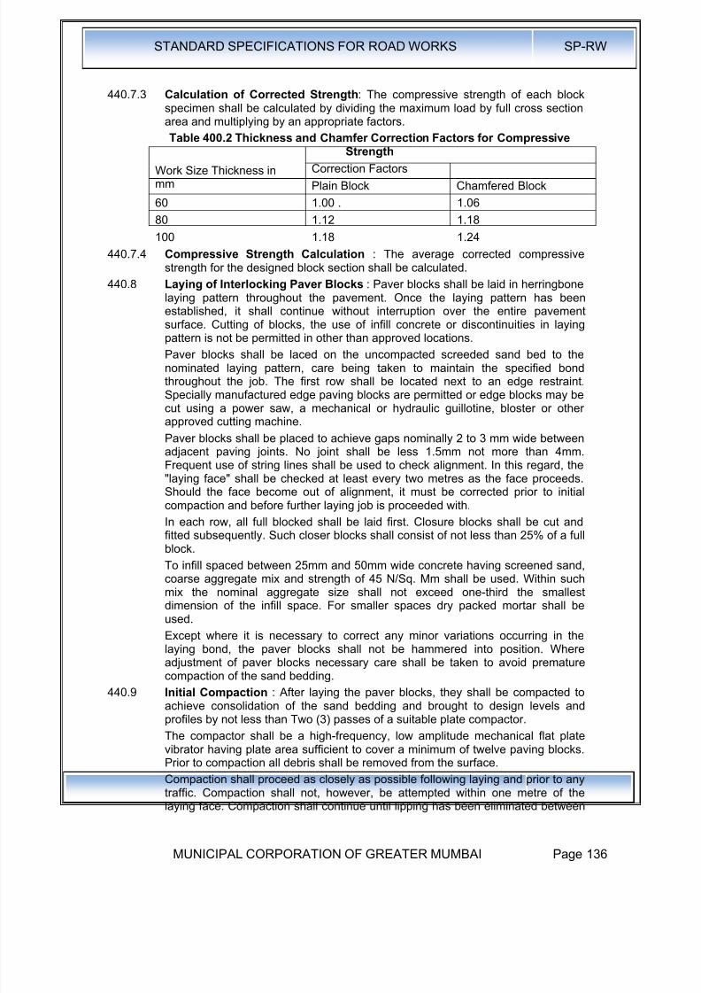
8/19/2019 MCGM Road Spec Volume -II
http://slidepdf.com/reader/full/mcgm-road-spec-volume-ii 140/176
STANDARD SPECIFICATIONS FOR ROAD WORKS SP-RW
MUNICIPAL CORPORATION OF GREATER MUMBAI Page 136
440.7.3 Calculation of Corrected Strength: The compressive strength of each blockspecimen shall be calculated by dividing the maximum load by full cross sectionarea and multiplying by an appropriate factors.
Table 400.2 Thickness and Chamfer Correction Factors for Compressive
StrengthWork Size Thickness inmm
Correction Factors
Plain Block Chamfered Block
60 1.00 . 1.06
80 1.12 1.18
100 1.18 1.24
440.7.4 Compressive Strength Calculation : The average corrected compressivestrength for the designed block section shall be calculated.
440.8 Laying of Interlocking Paver Blocks : Paver blocks shall be laid in herringbonelaying pattern throughout the pavement. Once the laying pattern has been
established, it shall continue without interruption over the entire pavementsurface. Cutting of blocks, the use of infill concrete or discontinuities in layingpattern is not be permitted in other than approved locations.
Paver blocks shall be laced on the uncompacted screeded sand bed to thenominated laying pattern, care being taken to maintain the specified bondthroughout the job. The first row shall be located next to an edge restraint.Specially manufactured edge paving blocks are permitted or edge blocks may becut using a power saw, a mechanical or hydraulic guillotine, bloster or otherapproved cutting machine.
Paver blocks shall be placed to achieve gaps nominally 2 to 3 mm wide betweenadjacent paving joints. No joint shall be less 1.5mm not more than 4mm.Frequent use of string lines shall be used to check alignment. In this regard, the"laying face" shall be checked at least every two metres as the face proceeds.Should the face become out of alignment, it must be corrected prior to initialcompaction and before further laying job is proceeded with.
In each row, all full blocked shall be laid first. Closure blocks shall be cut andfitted subsequently. Such closer blocks shall consist of not less than 25% of a fullblock.
To infill spaced between 25mm and 50mm wide concrete having screened sand,coarse aggregate mix and strength of 45 N/Sq. Mm shall be used. Within suchmix the nominal aggregate size shall not exceed one-third the smallestdimension of the infill space. For smaller spaces dry packed mortar shall beused.
Except where it is necessary to correct any minor variations occurring in thelaying bond, the paver blocks shall not be hammered into position. Whereadjustment of paver blocks necessary care shall be taken to avoid prematurecompaction of the sand bedding.
440.9 Initial Compaction : After laying the paver blocks, they shall be compacted toachieve consolidation of the sand bedding and brought to design levels andprofiles by not less than Two (3) passes of a suitable plate compactor.
The compactor shall be a high-frequency, low amplitude mechanical flat platevibrator having plate area sufficient to cover a minimum of twelve paving blocks.Prior to compaction all debris shall be removed from the surface.
Compaction shall proceed as closely as possible following laying and prior to anytraffic. Compaction shall not, however, be attempted within one metre of thelaying face. Compaction shall continue until lipping has been eliminated between
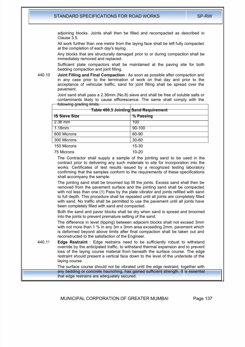
8/19/2019 MCGM Road Spec Volume -II
http://slidepdf.com/reader/full/mcgm-road-spec-volume-ii 141/176
STANDARD SPECIFICATIONS FOR ROAD WORKS SP-RW
MUNICIPAL CORPORATION OF GREATER MUMBAI Page 137
adjoining blocks. Joints shall then be filled and recompacted as described inClause 3.5.
All work further than one metre from the laying face shall be left fully compactedat the completion of each day's laying.
Any blocks that are structurally damaged prior to or during compaction shall beimmediately removed and replaced.
Sufficient plate compactors shall be maintained at the paving site for bothbedding compaction and joint filling.
440.10 Joint Filling and Final Compaction : As soon as possible after compaction andin any case prior to the termination of work on that day and prior to theacceptance of vehicular traffic, sand for joint filling shall be spread over thepavement.
Joint sand shall pass a 2.36mm (No.8) sieve and shall be free of soluble salts orcontaminants likely to cause efflorescence. The same shall comply with thefollowing grading limits.
Table 400.3 Jointing Sand RequirementIS Sieve Size % Passing
2.36 mm 100
1.18mm 90-100
600 Microns 60-90
300 Microns 30-60
150 Microns 15-30
75 Microns 10-20
The Contractor shall supply a sample of the jointing sand to be used in thecontract prior to delivering any such materials to site for incorporation into theworks. Certificates of test results issued by a recognized testing laboratoryconfirming that the samples conform to the requirements of these specificationsshall accompany the sample.
The jointing sand shall be broomed top fill the joints. Excess sand shall then beremoved from the pavement surface and the jointing sand shall be compactedwith not less than one (1) Pass by the plate vibrator and joints refilled with sandto full depth. This procedure shall be repeated until all joints are completely filledwith sand. No traffic shall be permitted to use the pavement until all joints havebeen completely filled with sand and compacted.
Both the sand and paver blocks shall be dry when sand is spread and broomedinto the joints to prevent premature setting of the sand.
The difference in level (lipping) between adjacent blocks shall not exceed 3mmwith not more than 1 % in any 3m x 3mm area exceeding 2mm. pavement whichis deformed beyond above limits after final compaction shall be taken out andreconstructed to the satisfaction of the Engineer.
440.11 Edge Restraint : Edge restrains need to be sufficiently robust to withstandoverride by the anticipated traffic, to withstand thermal expansion and to preventloss of the laying course material from beneath the surface course. The edgerestraint should present a vertical face down to the level of the underside of thelaying course.
The surface course should not be vibrated until the edge restraint, together withany bedding or concrete haunching, has gained sufficient strength. It is essential
that edge restrains are adequately secured.
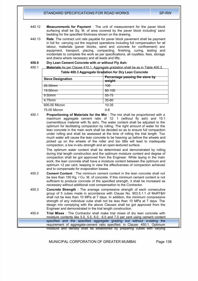
8/19/2019 MCGM Road Spec Volume -II
http://slidepdf.com/reader/full/mcgm-road-spec-volume-ii 142/176

8/19/2019 MCGM Road Spec Volume -II
http://slidepdf.com/reader/full/mcgm-road-spec-volume-ii 143/176
STANDARD SPECIFICATIONS FOR ROAD WORKS SP-RW
MUNICIPAL CORPORATION OF GREATER MUMBAI Page 139
moisture contents. Compaction of the mix shall be done in three layer withvibratory hammer fitted with a square or rectangular foot as described in Clause903.5.1.1 of M.O.R.T. & H. After establishing the optimum moisture, a set of sixcubes shall be cast at that moisture for the determination of compressivestrength on the 3rd and the 7th day. Trial mixes shall be repeated if the strengthis not satisfactory either by increasing cement content or using higher grade ofcement. After the mix design is approved, the Contractor shall construct a trialsection in accordance with Clause 601.7 of MoRT&H.
450.5 If during the construction of the trial length, the optimum moisture contentdetermined· as above is found to be unsatisfactory, the Contractor may makesuitable changes in the moisture content to achieve a satisfactory mix. The cubespecimens prepared with the changed moisture content should satisfy thestrength requirement. Before· production of the mix, natural moisture content ofthe aggregate should be determined on a day-to-day basis so that the moisturecontent could be adjusted. The mix finally designed should neither stick to therollers nor become too dry resulting in ravelling of surface.
450.6 Construction 450.6.1 General : The pace and programme of the lean concrete sub-base construction
shall be matching suitably with the programme of construction of the cementconcrete pavement over it. The sub-base shall be overlaid with cement concretepavement only after 7 days after sub-base construction.
450.6.2 Batching and Mixing : The batching plant shall be capable of proportioning thematerials by weight, each type of material being weighed separately inaccordance with Clause 602.9.3.2 of M.O.R.T.&H Specifications. The cementfrom the bulk stock shall be weighed separately from the aggregates. Thecapacity of batching and mixing plant shall be at least 25 per cent higher than theproposed capacity for the laying arrangements. The batching and mixing shall be
carried out preferably in a forced action central batching and mixing plant havingnecessary automatic controls to ensure accurate proportioning and mixing. Othertypes of mixers shall be permitted subject to demonstration of their satisfactoryperformance during the trial length. The type and capacity of the plant shall begot approved by the Engineer before commencement of the trial length. Theweighing balances shall be calibrated by weighing the aggregates, cement, waterand admixtures physically either by weighing with large weighing machine or in aweigh bridge. The accuracy of weighing scales of the batching plant shall bewithin ±2 per cent in the case of aggregates and ±1 per cent in the case ofcement and water.
The design features of Batching Plant should be such that the shifting operationsof the plant will not take very long tie when they are to be shifted from place to
place with the progress of the work.
450.6.3 Transporting : Plant mix lean concrete shall be discharge immediately from themixer, transported directly to the point where it is to be laid and protected fromthe weather by covering the tippers I dumpers with tarpaulin during transit. Theconcrete shall be transported by tipping trucks, sufficient in number to ensure acontinuous supply of material to feed the laying equipment to work at a uniformspeed and in an uninterrupted manner. The lead of the batching plant to pavingsite shall be such that the travel time available from mixing to paving as specifiedin Clause 450.5.5 will be adhered to.
450.6.4 Placing: Lean concrete shall be laid I placed by a paver with electronic sensor.The equipment shall be capable of laying the material in one layer in an even
manner without segregation, so that after compaction the total thickness is as
8/19/2019 MCGM Road Spec Volume -II
http://slidepdf.com/reader/full/mcgm-road-spec-volume-ii 144/176
STANDARD SPECIFICATIONS FOR ROAD WORKS SP-RW
MUNICIPAL CORPORATION OF GREATER MUMBAI Page 140
specified. The paving machine shall have high amplitude tamping bars to givegood initial compaction to the sub-base.
The laying of the two-lane road sub-base may be done either in full width or laneby lane. Preferably the lean concrete shall be placed and compacted across the
full width of the road, by constructing it in one go or in two lanes running forwardsimultaneously. Transverse and longitudinal construction joints shall bestaggered by 500-1000mm:and 200-400mm respectively from the corresponding joints in the overlaying concrete slabs.
450.6.5 Compaction :
450.6.5.1 The compaction shall be carried out immediately after the material is laid andlevelled. In order to ensure thorough compaction which is essential, rolling shallbe continued on the full width till there is no further visible movement under theroller and the surface is closed. The minimum dry density obtained shall be 97per cent of that achieved during the trial length construction vide Clause 601.7 ofMoRT&H Specifications. The densities achieved at the edges i.e. 0.5m from theedge shall not less than 95 per cent of that achieved during the trial construction
vide Clause 601.7 of MoRT&H Specifications.
450.6.5.2 The spreading, compacting and finishing of the lean concrete shall be carried outas rapidly as possible and the operation shall be so arranged as to ensure thatthe time between the mixing of the first batch of concrete in any transversesection of the layer and the final finishing of the same shall not exceed 90minutes when the concrete temperature is above 25 and below 30 degreeCelsius and 120 minutes if less than 25 degree Celsius. This period may bereviewed by the Engineer in the light of the results of the trial run but in no caseshall it exceed 2 hours. Work shall not proceed when the temperature of theconcrete exceeds 30 degree Celsius. If necessary, chilled water or addition of icemay resorted to for bringing down the temperature. It is desirable to stop
concreting when the ambient temperature is above 35°C. After compaction hasbeen completed, roller shall not stand on the compacted surface for the durationof the curing period except during commencement of next day's work near thelocation where work was terminated the previous day.
450.6.5.3 Double drum smooth-wheeled vibratory rollers of minimum 80 to 100 kN staticweight are considered to be suitable for rolling dry lean concrete. In case anyother roller is proposed, the same shall be got approved from the Engineer, afterdemonstrating its performance. The number of passes required to obtainmaximum compaction depends on the thickness of the lean concrete, thecompatibility of the mix, and the weight and type of the roller etc., and the sameas well as the total requirement of rollers for the job shall be determined duringtrial run by measuring the in-situ density and the scale of the work to be
undertaken.
450.6.5.4 In addition to the number of passes required for compaction there shall be apreliminary pass without vibration to bed the lean concrete down and again afinal pass without vibration to remove roller marks and to smoothen the surface.
Special care and attention shall be exercised during compaction near joints,kerbs, channels, side forms and around gullies and manholes. In case adequatecompaction is not achieved by the roller at these points, use of plat vibrator shallbe made, if so directed by the Engineer.
450.6.5.5 The final lean concrete surface on completion of compaction and immediatelybefore overlaying, shall be well closed, free from movement under roller and freefrom ridges, low spots, cracks, loose material, pot holes, ruts or other defects.
The final surface shall be inspected immediately on completion and all loose,segregated or defective areas shall be corrected by using fresh lean concrete
8/19/2019 MCGM Road Spec Volume -II
http://slidepdf.com/reader/full/mcgm-road-spec-volume-ii 145/176
STANDARD SPECIFICATIONS FOR ROAD WORKS SP-RW
MUNICIPAL CORPORATION OF GREATER MUMBAI Page 141
material laid and compacted as per Specification. For repairing honeycombedsurface, concrete with aggregates of size 10mm and below shall be spread andcompacted. It is necessary to check the level of the roller surface for compliance. Any level/thickness deficiency should be corrected after applying concrete withaggregates of size 10mm and below after roughening the surface. Similarly, thesurface regularity also should be checked with 3m straight edge. The deficiencyshould be made up with concrete with aggregates of size 10mm and below.450.6.5.6 Segregation of concrete in the dumpers shall be controlled bypremixing each fraction of the aggregates before loading in the bin of thebatching plant, by moving the dumper back and forth while discharging the mixon it and other means. Even paving operation shall be such that the mix does notsegregate.
450.6.6 Joints: Contraction and longitudinal joints shall be provided as per the drawing. .
At longitudinal or transverse construction joints, unless vertical forms are used,the edge of compacted material shall be cut back to a vertical face where thecorrect thickness of the properly compacted material has been obtained.
450.6.7 Curing : As soon as the lean concrete surface is compacted, curing shallcommence. One of the following two methods shall be adopted:
i) The initial curing shall be done by spraying with liquid curing compound. Thecuring compound shall be white pigmented or transparent type with waterretention index of 90 per cent when tested in accordance with 8S:7542.Curing compound shall be sprayed immediately after rolling is complete. Assoon as the curing compound has lost its tackiness, the surface shall becovered with wet Hessian for three days.
ii) Curing shall be done by covering the surface buy gunny bags/Hessian,which shall be kept continuously moist for 7 days by sprinkling water.
Tolerances for Surface Regularity, Level, Thickness, Density and Strength : The
tolerances for surface· regularity, level, thickness, density "and strength shallconform to the requirements given in Clause 903.5 of MoRT&H Specifications.Control of quality of materials and works shall be exercised by the Engineer inaccordance with Section 900 of MoRT&H. Specifications.
450.6.8 Traffic : No heavy commercial vehicles like trucks and buses shall be permittedon the lean concrete sub-base after its construction. Light vehicles if unavoidablemay, however, be allowed after 7 days of its construction with prior approval ofthe Engineer.
450.6.9 Measurements for Payment : The unit of measurement for dry lean concretepavement shall be the cubic metre of concrete placed, based on the net planareas for the specified thickness shown on the drawings or as directed by the
Engineer.450.6.10 Rate : The Contract unit rate payable for dry lean concrete, sub-base shall be
payment in full for carrying out the required operations including fullcompensation for all labour, materials and equipment, mixing, transport, placing,compacting, finishing, curing, testing and incidentals to complete the work as perSpecifications, all royalties, fees, storage and rents where necessary and allleads and lifts.

8/19/2019 MCGM Road Spec Volume -II
http://slidepdf.com/reader/full/mcgm-road-spec-volume-ii 146/176
STANDARD SPECIFICATIONS FOR ROAD WORKS SP-RW
MUNICIPAL CORPORATION OF GREATER MUMBAI Page 142
500.0 Road Surface Drainage Components
510.0 Cement Concrete Kerb and Kerb with Channel
510.1 Scope : This work shall consist of constructing cement concrete kerbs and kerbs
with channel in the central median and I or along the footpaths or separators inconformity with the lines, levels, and dimensions as specified in the drawings.
510.2 Materials: Kerbs and kerb with channel shall be provided in cement concrete ofGrade M-35 in accordance with Section 120 of these Specifications.
510.3 Type of Construction : These shall be cast-in-situ construction with suitablekerb casting machine in all situations except at locations where continuouscasting with equipment is not practicable. In those situations, precast concreteblocks shall be used.
510.4 Equipment: A continuous kerb casting equipment of adequate capacity andcontrols, capable of laying the kerbs in required cross-sections and producing awell-compacted mass of concrete free of voids and honeycombs, shall be used.
510.5 Construction Operations:
Kerb shall be laid on firm foundation of minimum 150mm thickness of cementconcrete of M-10 grade cast-in-situ or on extended width of pavement. Thefoundation shall have a projection of 50mm beyond the kerbstone. Before layingthe foundation of lean concrete, the base shall be levelled and slightly watered tomake it damp.
In the median portions in the straight reaches, the kerb shall be :cast incontinuous lengths. In the portions where footpath is provided and / or the slopeof the carriageway is towards median (as in case of super elevated portions),there shall be sufficient gap/recess left in the kerb to facilitate drainage openings.
After laying the kerbs and just prior to hardening of the concrete, saw cutgrooves shall be provided at 5m intervals or as specified by the Engineer.
Kerbs on the drainage ends such as along the footpath or the median in superelevated portions, shall be cast with monolithic concrete channels as indicated indrawings. The slope of the channel towards drainage pipes shall be ensured forefficient drainage of the road surface.
Vertical and horizontal tolerance with respect to true line and level shall be ±6mm.
510.6 Measurements for Payment : Cement concrete kerb I kerb with channel shallbe measured in linear metre for the complete item of work.
Foundation of kerb, where separately provided shall be measured in linear metre
for complete item of work.510.7 Rates: The Contract unit rates for cement concrete kerb I kerb with channel and
foundation for kerb shall be payment in full compensation for furnishing allmaterials, labour, tools, equipment for construction and other incidental costnecessary to complete the work.
550.0 Manholes:
The following sizes of manholes should be adopted for various inverts of the S.W.Drains.
Table 500.1
Sr.N
o.
Size of ManholesMinimumDepth upto
Invert
MaximumDepth upto
Invert
Remarks
1. 1.22m Dia at bottom 1.52m 2.29m
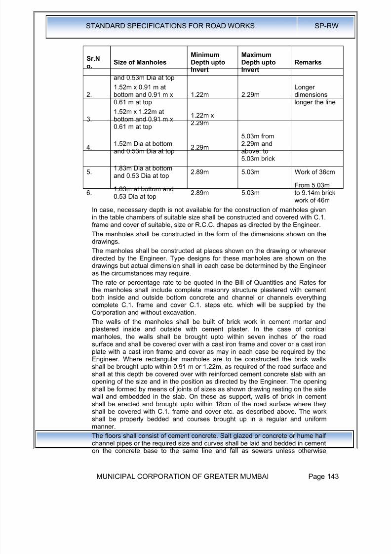
8/19/2019 MCGM Road Spec Volume -II
http://slidepdf.com/reader/full/mcgm-road-spec-volume-ii 147/176
STANDARD SPECIFICATIONS FOR ROAD WORKS SP-RW
MUNICIPAL CORPORATION OF GREATER MUMBAI Page 143
Sr.No.
Size of ManholesMinimumDepth uptoInvert
MaximumDepth uptoInvert
Remarks
and 0.53m Dia at top
2.1.52m x 0.91 m atbottom and 0.91 m x0.61 m at top
1.22m 2.29mLongerdimensionslonger the line
3.1.52m x 1.22m atbottom and 0.91 m x0.61 m at top
1.22m x2.29m
4.1.52m Dia at bottomand 0.53m Dia at top
2.29m
5.03m from2.29m andabove: to5.03m brick
5.1.83m Dia at bottom
and 0.53 Dia at top2.89m 5.03m Work of 36cm
6.1.83m at bottom and0.53 Dia at top
2.89m 5.03mFrom 5.03mto 9.14m brickwork of 46m
In case, necessary depth is not available for the construction of manholes givenin the table chambers of suitable size shall be constructed and covered with C.1.frame and cover of suitable, size or R.C.C. dhapas as directed by the Engineer.
The manholes shall be constructed in the form of the dimensions shown on thedrawings.
The manholes shall be constructed at places shown on the drawing or whereverdirected by the Engineer. Type designs for these manholes are shown on the
drawings but actual dimension shall in each case be determined by the Engineeras the circumstances may require.
The rate or percentage rate to be quoted in the Bill of Quantities and Rates forthe manholes shall include complete masonry structure plastered with cementboth inside and outside bottom concrete and channel or channels everythingcomplete C.1. frame and cover C.1. steps etc. which will be supplied by theCorporation and without excavation.
The walls of the manholes shall be built of brick work in cement mortar andplastered inside and outside with cement plaster. In the case of conicalmanholes, the walls shall be brought upto within seven inches of the roadsurface and shall be covered over with a cast iron frame and cover or a cast iron
plate with a cast iron frame and cover as may in each case be required by theEngineer. Where rectangular manholes are to be constructed the brick wallsshall be brought upto within 0.91 m or 1.22m, as required of the road surface andshall at this depth be covered over with reinforced cement concrete slab with anopening of the size and in the position as directed by the Engineer. The openingshall be formed by means of joints of sizes as shown drawing resting on the sidewall and embedded in the slab. On these as support, walls of brick in cementshall be erected and brought upto within 18cm of the road surface where theyshall be covered with C.1. frame and cover etc. as described above. The workshall be properly bedded and courses brought up in a regular and uniformmanner.
The floors shall consist of cement concrete. Salt glazed or concrete or hume halfchannel pipes or the required size and curves shall be laid and bedded in cementon the concrete base to the same line and fall as sewers unless otherwise

8/19/2019 MCGM Road Spec Volume -II
http://slidepdf.com/reader/full/mcgm-road-spec-volume-ii 148/176
STANDARD SPECIFICATIONS FOR ROAD WORKS SP-RW
MUNICIPAL CORPORATION OF GREATER MUMBAI Page 144
directed. Both sides of the channel pipes shall be benched up in concrete andrendered in cement 20mm thick and formed to a slope of not less than 1 in 12 tothe channel.
Whenever a pipe enters or leaves manholes bricks on edge must be cut to a
proper form and laid around the upper half of the pipe so as to form an arch. Allaround the pipe, there shall be a joint of cement mortar 12mm thick between itand the bricks. The ends of all pipes shall be properly built in and neatly finishedwith cement mortar.
Where the depth of the invert exceeds 1 m below the surface of the galvanizedwrought iron or cast iron steps of approved pattern shall be built in the brick workground every four courses with such additional hand irons as may be necessaryfor safety.
560.0 Water Entrances:
The chamber for water entrances shall be constructed of bricks work in 1:5cement mortar plastered with cement plastering 12mm thick. The bed of thechamber shall consist of 23cm layer of 1 :4:8 cement concrete. The invert shallbe formed of cement concrete as shown in the drawing and shall be plasteredwith cement plastering 12mm thick. The parda of diaphragm shall be of cast iron25mm thick and shall be so fixed as to carry the dhapas and to dip into the waterseal to a depth of 20cm. The part of the chamber which is shown on drawing asbelow the surface of the road, shall be covered with blue stone dhapas as shownon the drawing. The other part of the chamber shall be covered with twomosquito proof close C.1. gratings; fair weather plates in the case of full sizedwater gullies and one for single water gullies the grating or gratings beingsupported on C.1. frame as shown on the drawing.
Whenever any hole or other communication has to be cut into the wall or madewith a drain or sewer or a manhole or into or with other masonry, the hole or
communication shall be cut or made neatly to the requisite value size and pipetail piece, elbow or other article or work for which it is required shall be neatlyand soundly stopped around with, or built in cement and sand (1 to 1). The ratefor cutting the hole or that for the work or which the communication is requiredshall include the cost of such stopping. that of any making good that may berequired and also that of any arrangements which the contractors may have tomake in order to stop the access of sewage or water during the execution of theirwork. No payment will be allowed to the contractors for cutting out any portion ofthe new work for the purpose of other work under contract or in such for stoppingand making good as above described. If the sewer or the drain into which hole orcommunication is to be cut is in a working condition and if there is a likelihood ofthe workmen being exposed to the danger arising from the sewage gases, such
work and also that of removing such or plug shall be done by the municipal stafftrained for such work and under the supervision of responsible officers as maybe directed .by the Engineer and the cost of such work shall be borne by theContractor.
Payment for the items of making connection shall be made only if the connectionis made by making a hole in the masonry of the existing manhole or sump etc.,and making it good from inside and outside. No payment shall be made if theconnection is made to existing pipe.
All cement work pointing, plastering and concrete work shall be shaded from thesun and the surface kept moist until, in the opinion of the Engineer, it isthoroughly set.
Whenever a new work meets the old, certain portions of the old work as may beordered by the Engineer, shall be cut away in order that the new work may be
8/19/2019 MCGM Road Spec Volume -II
http://slidepdf.com/reader/full/mcgm-road-spec-volume-ii 149/176
STANDARD SPECIFICATIONS FOR ROAD WORKS SP-RW
MUNICIPAL CORPORATION OF GREATER MUMBAI Page 145
properly bonded into the old. No payment will be allowed to the Contractorscutting away any portion of the work done under this contract or the purpose ofother similar work or in such case for bonding and making good the same asabove described.
570.0 Footpaths, Medians, Shoulders, Islands & Road Arboriculture571.0 Footpaths, Medians & Road Arboriculture
571.1 Description : The work shall consist of constructing finishing to footpaths,medians and/or separators and landscaped areas at locations specified in thedrawings in conformity with the lines and levels and dimensions ·as specified Inthe drawings or as directed by the Engineer. The scope of the work shall includeprovision of all drainage arrangements within the footpaths as shown on thedrawings or as directed.
571.2 Construction Operation: General: All utility diversions within the footpath and /or median and / or other paved areas shall be completed to the satisfaction of theEngineer prior to commending footpath and other pavement finishing.
All drainage works crossing the footpath and / or median shall be laid to therequired slope and connected to the drains / sumps / storm water drain /drainage chutes gullies etc., as indicated in Drawings and Specification prior tocommencing footpath and other pavement finishing.
Installation of all street lighting installations, traffic sign and traffic signal posts,and other utility appurtenances and road side barriers shall be completed prior tocommencing the footpath and other pavement finishing.
All permanent obstacles within the footpath area, such as manhole covers, shallbe adjusted to the correct finished levels prior to commencing footpath and otherpavement finishing.
If footpath and / or median finishing is undertaken prior to completion of the
adjacent carriageway construction, the contractor shall protect the footpath and /or median finishing from damage from road works operations, and shall takewhatever measures are deemed necessary by the Engineer to protect thefinished works.
The contractor shall provide and maintain a temporary surface of completedgranular sub-base material for pedestrians until such time as. the permanentfinishes are constructed.
572.0 Shoulders & Islands:
572.1 Scope: The work shall consist of constructing shoulder (hard / paved / earthenwith brick or stone block edging) on either side of the pavement, median in theroad dividing the carriageway into separate lanes and islands for channelising
the traffic at junctions in accordance with the requirements of theseSpecifications and in conformity with the lines, grades and cross-section shownon the drawings or as directed by the Engineer.
572.2 Materials : Shoulder on either side of the road may be of selected earth Igranular material I paved conforming to the requirements of Clause 150 or 200and the median may be of selected earth.
Median I Traffic islands shall be raised and kerbed at the perimeter and theenclosed area filled with earth and suitably covered with grass turf I shrubs and Ior paved as per Clause 571.
Paved shoulders shall consist of sub-base, base and surfacing courses, . asshown in the drawings and materials for the same shall conform to relevant
Specifications of the corresponding items. Where paved or hard shoulders are

8/19/2019 MCGM Road Spec Volume -II
http://slidepdf.com/reader/full/mcgm-road-spec-volume-ii 150/176
STANDARD SPECIFICATIONS FOR ROAD WORKS SP-RW
MUNICIPAL CORPORATION OF GREATER MUMBAI Page 146
not provided, the pavement shall be provided with brick I stone block edging asshown in the drawings.
Size of Shoulders I Median I Islands : Shoulder (earthen I hard I paved) Imedian I traffic island dimensions shall be as shown on the drawings or as
directed by the Engineer.572.3 Construction Operations :
572.3.1 Shoulder : The sequence of operations shall be such that the construction ofpaved shoulder is done in layers each matching the thickness of adjoiningpavement layer. Only after a layer of pavement and corresponding layers inpaved and earth shoulder portion have been laid and compacted, theconstruction of next layer of pavement and shoulder shall be taken up.
Where the materials in adjacent layers are different, these shall be laid togetherand the pavement layer shall be compacted first. The corresponding layer inpaved shoulder portion shall be compacted thereafter, which shall be followed bycompaction of earth shoulder layer. The adjacent layers having same materialshall be laid and compacted together.
In all case where paved shoulders have to be provided along side of existingcarriageway, the existing shoulders shall be excavated in full width and to therequired depth as per Clause 103.5.
Compaction requirement of earthen shoulder shall be as per Table 100.5. In thecase of bituminous courses, work on shoulder (earthen I hard I paved), shall startonly after .the pavement course has been laid compacted.
During all stages of shoulder (earthen I hard I paved) construction, the requiredcross-fall shall be maintained to drain off surface water. Regardless of themethod of laying, all shoulder construction material shall be placed directly onthe shoulder. Any spilled material dragged on to the pavement surface shall beimmediately removed, without damage to the pavement, and the area so affectedthoroughly cleaned.
572.3.2 Median and Islands : Median and Islands shall be constructed in a mannersimilar to shoulder up to the road level. Thereafter the median and islands, ifraised, shall be raised at least 300mm by using kerb stones of approved materialand dimensions and suitably finished and painted as directed by the Engineer. Ifnot raised, the median and islands shall be differentiated from the shoulder Ipavement as the case may be, as directed by the Engineer. The confined area ofthe median and islands shall be filled with local earth or granular material or anyother approved material and compacted by plate compactor I power rammer.The confined area after filling with earth shall be turfed with grass or planted withshrubs and In case of granular fill it can be finished with tiles I slabs as directed
by the Engineer.572.3.2.1 Brick I Stone Block Edging : The bricks I stone blocks shall be laid on the
edge, with the length parallel to the transverse direction of the road. They shallbe laid on a bed of 25mm sand, set carefully, rolled into position by a light rollerand made flush with the finished level of the pavement. .
572.3.2.2 Surface Finish and Quality Control of Works : The surface finish ofconstruction shall conform to the requirements of Clause600.cntrol on the qualityof materials and works shall be exercised by the Engineer in accordance withSection 600.
572.3.2.3 Measurement for Payment: Shoulder (earthen I hard I paved), island andmedian construction shall be measured as finished work in position as below:
a) For excavation in Cu. M.b) For earthwork I granular fill in C~. M.
8/19/2019 MCGM Road Spec Volume -II
http://slidepdf.com/reader/full/mcgm-road-spec-volume-ii 151/176
STANDARD SPECIFICATIONS FOR ROAD WORKS SP-RW
MUNICIPAL CORPORATION OF GREATER MUMBAI Page 147
c) For sub-base, base, surfacing courses in units as for respective items
d) For kerb in running metres
e) For turfing and tile I slab in Sq. M.
f) For brick I stone block edging in Sq. M.
572.3.2.4 Rate : The Contract unit rate for shoulder (hard I paved I earthen with brick orstone block edging), island and median construction shall be payment in full forcarrying out the required operations including full compensation for allcomponents listed in Clause 401.8 "(i) to (v) as applicable. The rate for brick Istone block edging shall include the cost of sand cushion.
573.0 Footpaths and Separators:
573.1 Scope : The work shall consist of constructing footpaths and I or separators atlocations as specified in the drawings or as directed by the Engineer. The lines,levels and dimensions shall be as per the drawings. The scope of the work shallinclude provision of all drainage arrangements as shown in the drawings or asdirected.
573;2 Materials: The footpaths and separators shall be constructed with any of thefollowing types:
a) Cast-in-situ cement concrete for Grade M-35 as per Section 400 of theSpecifications,
b) Precast cement concrete blocks I tiles of M-35 Grade as per Section 400 ofthe Specifications.
c) Natural stone slab cut and dressed from stone of good and sound quality,uniform in texture, free from defects, and at least equal to a sample submittedby the Contractor and approved by the Engineer. The minimum thickness ofthe natural stone slab shall be 25mm and minimum size shall be 300mm x300mm.
d) Precast un-reinforced concrete paving blocks of 40 to 50mm thickness: Asper Clause 440.
573.3 Construction Operations: Drainage pipes below the footpath originating fromthe kerbs shall be first laid in the required slope and connected to the drains Isumps I storm water drain I drainage chutes as per provisions of the drawings, oras specified.
Portion on back side of kerbs shall be filled and compacted with granular sub-base material as per Clause 401 of the Specifications in the specified thickness.
The base shall be prepared and finished to the required lines, levels, anddimensions as indicated in the drawings with the following:
a) Minimum 150mm thick, compacted granular sub-base material as perClause 401 of the Specifications,
b) Minimum 25mm thick cement concrete of Grade M-15.
Over the prepared base, precast concrete blocks I tiles I natural stone slabs andI or cast-in-situ slab shall be set I laid
573.3.1 Precast cement concrete blocks I tiles / natural stone slab: The blocks I tiles/ slabs shall be set on a layer of average 12mm thick cement sand mortar (1 :3)laid on prepared base in such a way that there is no rocking. The gaps betweenthe blocks I tiles I slabs shall not be more than 12mm and shall be filled withcement-sand mortar (1:3).
573.3.2 Cast-In-Situ Cement Concrete : The minimum thickness of the cement concrete
shall be 25mm and it shall be cast on the prepared base in panels of specified
8/19/2019 MCGM Road Spec Volume -II
http://slidepdf.com/reader/full/mcgm-road-spec-volume-ii 152/176
STANDARD SPECIFICATIONS FOR ROAD WORKS SP-RW
MUNICIPAL CORPORATION OF GREATER MUMBAI Page 148
size in a staggered manner. Construction joints shall be provided as per Section400 of the Specifications.
573.3.3 Measurements for Payment : Footpaths and separators shall be measured inSq. M. between inside of kerbs.
573.3.4 Rates : Contract unit rates shall be inclusive of full compensation of all labour,materials, tools, equipment and incidentals to construction of footpaths. Cost ofproviding pipes and arrangement for their discharge into appropriate drainagechannels shall be incidental to the construction of footpaths.
580.0 Road Markings & Street Furniture:
580.1 Specifications of Traffic Signs and Road Markings:
580.1.1 Traffic Signs : Temporary traffic and construction signs are to be providedduring construction and maintenance operations for traffic diversion andpedestrian safety.
580.1.2 Road Marking:
580.1.2.1 Road markings shall be of hot applied thermoplastic materials with glass
reflectorising beads as per relevant clauses of Section 803 of MoRTHSpecifications.
580.1.2.2 Road markings shall be as per IRC : 35-1997. These markings shall be appliedto road centre lines, edge lines, continuity line, stop lines, give-way lines,diagonal/chevron markings, zebra crossing and at parking areas by means of anapproved self-propelled machine which has a satisfactory cut-off valves capableof applying broken lines automatically.
580.1.2.3 Synthetic enamel paints shall be used to display details of structure number,span arrangement etc. on all culverts and bridges with required description asper M.O.S.T. guidelines.
580.2 Specifications of Thermo-Plastic Road Marking:
580.2.1 All markings should be strictly in accordance with code of practice for roadmarking, paintslRC-35 and as specified by the Engineer-InCharge.
580.2.2 The Thermoplastic material shall be homogeneous / composed of aggregate,pigment, resins and glass reflector zing beads and shall conform to 8.S.3262Part-I / ASTMD36.
580.2.3 Requirements:
580.2.3.1 Composition: The material shall be free from all skins, dirt and foreign objects.
Sr.No.
Component White Yellow
1. Binder · 18.0 Min. 18.0 Min.
2. Glass Beads 20.0 Min. 20.0 Min.
3. Titanium Dioxide 10.0 Min. -
580.2.4 Properties : The properties of thermoplastic material, when tested in accordancewith A.S.T.M.D. 361 BS-3262 (Part-I) shall be as below:
i) Luminance:
White Day Light - Luminance at 45° - 65% min, as per AASHTO M 249 -
Yellow Day Light - Luminance at 45° - 45% as per AASHTO M249
ii) Drying Time : When applied at a temperature specified by the manufacturerand to the required thickness, the material shall set to beat traffic in not morethan 15 min.
iii) Skid Resistance - not less than 45 as per BS-6044.
8/19/2019 MCGM Road Spec Volume -II
http://slidepdf.com/reader/full/mcgm-road-spec-volume-ii 153/176
STANDARD SPECIFICATIONS FOR ROAD WORKS SP-RW
MUNICIPAL CORPORATION OF GREATER MUMBAI Page 149
iv) Cracking Resistance at Low Temperature: The material $hall show nocracks on application to concrete blocks.
v) Softening Point: 102.5 as per 9.5c as per ASTMD 36.
vi) Flow Resistance: Not more than 25% per ASSHTO M249.
vii) Yellowness Index (for white thermoplastic paint) not more than 0.12 as per AASHTO M249.
580.2.4.1 Reflectorisation shall be achieved by incorporation of beads. The grading andother properties of the beads shall be as under:
580.2.4.2 The glass beads shall be transparent, colourless and free from milkiness, darkparticles and excessive air inclusions. The thermoplastic material shall readilyget screeded 1 extruded at temperature specified by the manufacturers forrespective method of application to produce a line of specified thickness whichshall be continuous and uniform in shape having clear and sharp edges.
580.2.4.3 The subject material upto heating to application temperature, shall not exudefumes which are toxic, obnoxious or injurious to persons or property.
580.2.4.4 Properties of finished road marking shall be as under:i) The strip shall not be slippery when wet.
ii) After application and proper drying the strip shall not show appreciabledeformation or discolouration under traffic.
iii) The marking shall· not deteriorate by contact with sodium chloride or oildrippings from traffic.
iv) The strip of marking shall maintain its original dimensions in position. Coldductility of the material shall be such as to permit normal movement with theroad surface without chopping or cracking.
v) The colour of yellow marking shall conform to LS. Code No. 356 as given in
IS 164.vi) Durability: The road markings shall be highly durable in all weather and
traffic conditions. It shall last for a period of five years. The markings whentested shall show no sign of cracking, flaking, peeling off or disintegration.
580.2.4.5 The marking shall be done by machine.
580.2.4.6 The thermoplastic material shall be applied hot either by screeding of extrusionmachine at a temperature within the range specified by the manufacturer.
580.2.4.7 The surface shall be thoroughly cleaned of all dust, dirt, grease, oil and all otherforeign matter before application of the paint.
580.2.4.8 The paint shall be applied in intermittent or continuous lines as directed andspecified and of uniform thickness of at least 2.5mm, unless specified otherwise.
580.2.4.9 Where arrows or letters are to be provided, the paint may be hand applied.
580.2.4.10 The tenderer shall furnish a copy of certified test reports from the manufacturerof glass beads obtained from a reputed laboratory showing results of all the testsspecified and shall certify that the material meets all the requirements ofspecifications.
580.2.4.11 The thermoplastic material used should be complying to specifications ofB.S.3262 (Part-I) / ASTMD-36.
590.0 Reinforced Earthwork
590.1 Scope : The work covers the construction of reinforced earth structures, togetherwith the construction of earthwork in layers, assembly and erection of reinforcing
elements and placement of facing panels and all associated components.
8/19/2019 MCGM Road Spec Volume -II
http://slidepdf.com/reader/full/mcgm-road-spec-volume-ii 154/176
STANDARD SPECIFICATIONS FOR ROAD WORKS SP-RW
MUNICIPAL CORPORATION OF GREATER MUMBAI Page 150
590.2 Reinforcing Element:
590.2.1 The reinforcing element shall be Geotextile, aluminium alloy strip, copper strip,copper strip, carbon steel strip, mats of metal or synthetic grids, or any otherproprietary material which may be approved by the Engineer and indicated on
the drawings.590.2.2 Geotextile : The material shall conform to Clause 260.
590.2.3 Aluminium alloy strip shall comply with BS:1470 quality 5454 in the H 24condition.
590.2.4 Copper strip shall comply with BS:2870 quality C 101 or C 102 in the 1/2 Hcondition and shall have 0.2 per cent proof stress of not less than 180 N/mm2
590.2.5 Carbon steel strip which shall be galvanized shall comply with BS:1449 (Part 1),either quality KHR 34/20 P or quality 50/35 P, each having a silicon content ofnot less than 0.25 per cent and not more than 0.40 per cent. The fabricatedelement shall be galvanized in accordance with BS:729, and the average zinccoating weight for any individual test area shall not be less than 1000 Gm 1 Sq.
M.590.2.6 Stainless steel strip shall comply with BS:1449 (Part 2) quality 316 S 31· or 3/6 S
33 except that the material shall be cold: rolled to provide a 0.2 per cent proofstress of not less than 400 N 1 Sq. Mm. and the tensile strength shall not be lessthan 540 N 1 Sq. M.
590.2.7 All metallic components buried in soil shall be of electrolytically compatiblematerials.
590.2.8 Geogrids : The supply of geo-grids shall carry a certification of BIS or ISO 9002for all works. While the reinforcing element for wall or slope portion shall be withmono oriented Geo-grid, the reinforcement for the foundation of a reinforcedearth wall or slope shall be with bidirectionally oriented Geo-grid. For mono
oriented Geo-grid, the characteristic design tensile strength at a strain notexceeding 10 per cent in 100 years shall be at least 40 KN 1 m when measuredas per GRI:GG3. The strength for bi-directionally oriented Geo-grid in thelongitudinal direction shall be at least 40 KN 1 m at a maximum elongation of 15per cent. The Geo-grid shall be inert to all naturally occurring chemicals, mineralsand salts found in soil.
590.3 Earth Fill : The fill material fat reinforced earth structures shall have an angle ofinterface friction between the compacted fill and the reinforcing element of notless than 25°C, measured in accordance with 18:1326 (Part 1). The soil shouldbe predominantly coarse grained; not more than 10 per cent of the particles shallpass 75 micron sieve. The soil should have properties such that the salts in thesoil should not react chemically. or electrically with the reinforcing elements in an
adverse manner.590.4 Facia Material:
590.4.1 The facing shall comprise of one of following:
i) Reinforced concrete (Cast in situ or precast) slabs
ii) Plain cement concrete form fill hollow block (Precast)
iii) Masonry construction, Rubble Facia
iv) Other proprietary and patented proven system
The facing shall be sufficiently flexible to withstand any deformation of the fill.
590.4.2 Facia unit joint filler should be durable resistant to the effect of air pollution andwater / saline water.
590.4.3 Bedding material shall consist of either cement mortar or a durable gasketseating such as resin bonded cork strip.
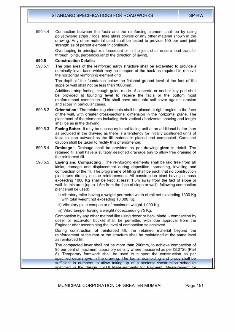
8/19/2019 MCGM Road Spec Volume -II
http://slidepdf.com/reader/full/mcgm-road-spec-volume-ii 155/176
STANDARD SPECIFICATIONS FOR ROAD WORKS SP-RW
MUNICIPAL CORPORATION OF GREATER MUMBAI Page 151
590.4.4 Connection between the facia and the reinforcing element shall be by usingpolyethylene strips I rods, fibre glass dowels or any other material shown in thedrawing. Any other material used shall be tested to provide 100 per cent jointstrength as of parent element !n continuity.
Overlapping in principal reinforcement or in the joint shall ensure load transferthrough joints, perpendicular to the direction of laying.
590.5 Construction Details:
590.5.1 The plan area of the reinforced earth structure shall be excavated to provide anominally level base which may be stepped at the back as required to receivethe horizontal reinforcing element grid.
The depth of the foundation below the finished ground level at the foot of theslope or wall shall not be less than 1000mm.
Additional strip footing, trough guide made of concrete or anchor key pad shallbe provided at founding level to receive the facia or the bottom mostreinforcement connection. This shall have adequate soil cover against erosion
and scour in particular cases.590.5.2 Orientation : The reinforcing elements shall be placed at right angles to the face
of the wall, with greater cross-sectional dimension in the horizontal plane. Theplacement of the elements including their vertical I horizontal spacing and lengthshall be as in the drawing.
590.5.3 Facing Batter: It may be necessary to set facing unit at an additional batter thanas provided in the drawing as there is a tendency for initially positioned units offacia to lean outward as the fill material is placed and compacted. Care andcaution shall be taken to rectify this phenomenon.
590.5.4 Drainage : Drainage shall be provided as per drawing given in detail. Theretained fill shall have a suitably designed drainage bay to allow free draining of
the reinforced fill.590.5.5 Laying and Compacting : The reinforcing elements shall be laid free from all
kinks, damage and displacement during deposition, spreading, levelling andcompaction of the fill. The programme of filling shall be such that no constructionplant runs directly on the reinforcement. All construction plant having a massexceeding 1000 Kg shall be kept at least 1.5m away from the fact of slope orwall. In this area (up to 1.5m from the face of slope or wall), following compactionplant shall be used:
i) Vibratory roller having a weight per metre width of roll not exceeding 1300 Kgwith total weight not exceeding 10,000 Kg.
ii) Vibratory plate compactor of maximum weight 1,000 Kg.
iii) Vibro tamper having a weight not exceeding 75 Kg.Compaction by any other method like using dozer or back blade ,- compaction bydozer or excavator bucket shall be permitted with due approval from theEngineer after ascertaining the level of compaction so achieved.
During construction of reinforced fill, the retained material beyond thereinforcement at the rear or the structure shall be maintained at the same levelas reinforced fill.
The compacted layer shall not be more than 200mm, to achieve compaction of95 per cent of maximum laboratory density where measured as per IS:2720 (Part8). Temporary formwork shall be used to support the construction as perspecified details give in the drawing. The forms, scaffolding and props shall be
sufficient in numbers to allow taking up of a sectoral construction schedulespecified in the design. 590.6 Measurements for Payment: Measurement for

8/19/2019 MCGM Road Spec Volume -II
http://slidepdf.com/reader/full/mcgm-road-spec-volume-ii 156/176
STANDARD SPECIFICATIONS FOR ROAD WORKS SP-RW
MUNICIPAL CORPORATION OF GREATER MUMBAI Page 152
reinforcing elements shall be in linear metre for anchor strips or in Sq. M. for geo-grid I geotextile etc.
The measurement for facia shall be in Square Metres. The measurement forfoundation for facia and capping beam shall be in linear metres. Measurement
for compacted earthfill shall be in Cubic Metres for compacted soil.590.7 Rates : Rate shall include cost of labour, plant hire, material storage andhandling expenses, for completing the works.
Rate for providing reinforcing elements shall include material cost, alltransportation costs and storage of the same as per special provisions. The rateshall also include cost of laying of the reinforcing elements including all overlaps, jointing or stitching, heat bonding or extension.
Rate for facia fixing shall include cost of joints, all necessary temporaryformwork, scaffolding and all lifts and leads, if any, as shown in the drawing,unless otherwise specified to the treated separately along with foundation orslope / wall kerb at the top of slope or wall. Rate for bed block and capping beamshall include all items of excavation, concrete, reinforcing steel, formwork, labourand equipment.
Rate for soil fill shall include compaction as desired in requisite layers throughmechanical means, cost of hire or labour for plant operations, dressing andlevelling slopes, including special measures for edge reinforcement as shown inthe drawing.
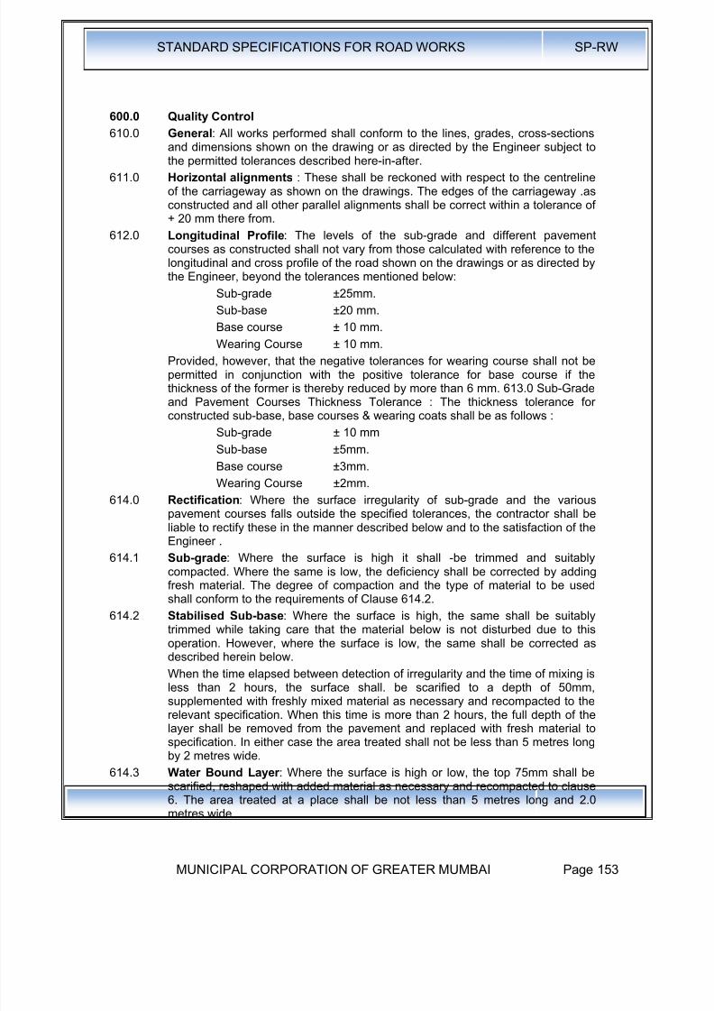
8/19/2019 MCGM Road Spec Volume -II
http://slidepdf.com/reader/full/mcgm-road-spec-volume-ii 157/176
STANDARD SPECIFICATIONS FOR ROAD WORKS SP-RW
MUNICIPAL CORPORATION OF GREATER MUMBAI Page 153
600.0 Quality Control
610.0 General: All works performed shall conform to the lines, grades, cross-sectionsand dimensions shown on the drawing or as directed by the Engineer subject to
the permitted tolerances described here-in-after.611.0 Horizontal alignments : These shall be reckoned with respect to the centreline
of the carriageway as shown on the drawings. The edges of the carriageway .asconstructed and all other parallel alignments shall be correct within a tolerance of+ 20 mm there from.
612.0 Longitudinal Profile: The levels of the sub-grade and different pavementcourses as constructed shall not vary from those calculated with reference to thelongitudinal and cross profile of the road shown on the drawings or as directed bythe Engineer, beyond the tolerances mentioned below:
Sub-grade ±25mm.
Sub-base ±20 mm.
Base course ± 10 mm.
Wearing Course ± 10 mm.
Provided, however, that the negative tolerances for wearing course shall not bepermitted in conjunction with the positive tolerance for base course if thethickness of the former is thereby reduced by more than 6 mm. 613.0 Sub-Gradeand Pavement Courses Thickness Tolerance : The thickness tolerance forconstructed sub-base, base courses & wearing coats shall be as follows :
Sub-grade ± 10 mm
Sub-base ±5mm.
Base course ±3mm.
Wearing Course ±2mm.614.0 Rectification: Where the surface irregularity of sub-grade and the various
pavement courses falls outside the specified tolerances, the contractor shall beliable to rectify these in the manner described below and to the satisfaction of theEngineer .
614.1 Sub-grade: Where the surface is high it shall -be trimmed and suitablycompacted. Where the same is low, the deficiency shall be corrected by addingfresh material. The degree of compaction and the type of material to be usedshall conform to the requirements of Clause 614.2.
614.2 Stabilised Sub-base: Where the surface is high, the same shall be suitablytrimmed while taking care that the material below is not disturbed due to this
operation. However, where the surface is low, the same shall be corrected asdescribed herein below.
When the time elapsed between detection of irregularity and the time of mixing isless than 2 hours, the surface shall. be scarified to a depth of 50mm,supplemented with freshly mixed material as necessary and recompacted to therelevant specification. When this time is more than 2 hours, the full depth of thelayer shall be removed from the pavement and replaced with fresh material tospecification. In either case the area treated shall not be less than 5 metres longby 2 metres wide.
614.3 Water Bound Layer : Where the surface is high or low, the top 75mm shall bescarified, reshaped with added material as necessary and recompacted to clause
6. The area treated at a place shall be not less than 5 metres long and 2.0metres wide.
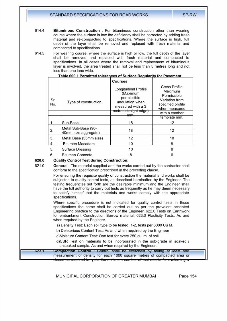
8/19/2019 MCGM Road Spec Volume -II
http://slidepdf.com/reader/full/mcgm-road-spec-volume-ii 158/176
STANDARD SPECIFICATIONS FOR ROAD WORKS SP-RW
MUNICIPAL CORPORATION OF GREATER MUMBAI Page 154
614.4 Bituminous Construction : For bituminous construction other than wearingcourse where the surface is low the deficiency shall be corrected by adding freshmaterial and re-compacting to specifications. Where the surface is high, fulldepth of the layer shall be removed and replaced with fresh material andcompacted to specifications.
614.5 For wearing course, where the surface is high or low, the full depth of the layershall be removed and replaced with fresh material and compacted tospecifications. In all cases where the removal and replacement of bituminouslayer is involved, the area treated shall not be less than 5 metres long and notless than one lane wide.
Table 600.1 Permitted tolerances of Surface Regularity for Pavement
Courses
Sr.No. Type of construction
Longitudinal Profile(Maximumpermissible
undulation whenmeasured with a 3
metres straight edge)mm.
Cross ProfileMaximum
Permissible
Variation fromspecified profilewhen measuredwith a cambertemplate mm.
1. Sub-Base 18 12
2.Metal Sub-Base (90-40mm size aggregate)
18 12
3. Metal Base (55mm size) 12 10
4. Bitumen Macadam 10 8
5. Surface Dressing 10 8
6. Bitumen Concrete 8 6
620.0 Quality Control Test during Construction:
621.0 General : The material supplied and the works carried out by the contractor shallconform to the specification prescribed in the preceding clause.
For ensuring the requisite quality of construction the material and works shall besubjected to quality control tests, as described hereinafter, by the Engineer. Thetesting frequencies set forth are the desirable minimum and the Engineer shallhave the full authority to carry out tests as frequently as he may deem necessaryto satisfy himself that the materials and works comply with the appropriatespecifications.
Where specific procedure is not indicated for quality control tests in thosespecifications the same shall be carried out as per the prevalent acceptedEngineering practice to the directions of the Engineer. 622.0 Tests on Earthworkfor embankment Construction Borrow material: 623.0 Plasticity Tests: As andwhen required by the Engineer.
a) Density Test: Each soil type to be tested, 1-2, tests per 8000 Cu M.
b) Deleterious Content Test: As and when required by the Engineer
c)Moisture Content Test: One test for every 250 cu. m. of soil.
d)CBR Test on materials to be incorporated in the sub-grade in soaked Iunsoaked sample. As and when required by the Engineer.
623.1 Compaction Control : Control shall be exercised by taking at least one
measurement of density for each 1000 square metres of compacted area orclosed as required to: yield the minimum number of test results for evaluating a
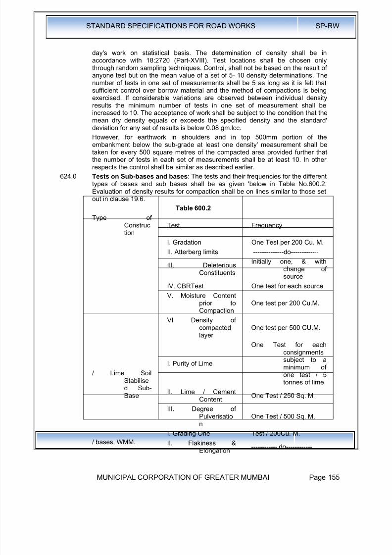
8/19/2019 MCGM Road Spec Volume -II
http://slidepdf.com/reader/full/mcgm-road-spec-volume-ii 159/176
STANDARD SPECIFICATIONS FOR ROAD WORKS SP-RW
MUNICIPAL CORPORATION OF GREATER MUMBAI Page 155
day's work on statistical basis. The determination of density shall be inaccordance with 18:2720 (Part-XVIII). Test locations shall be chosen onlythrough random sampling techniques. Control, shall not be based on the result ofanyone test but on the mean value of a set of 5- 10 density determinations. Thenumber of tests in one set of measurements shall be 5 as long as it is felt thatsufficient control over borrow material and the method of compactions is beingexercised. If considerable variations are observed between individual densityresults the minimum number of tests in one set of measurement shall beincreased to 10. The acceptance of work shall be subject to the condition that themean dry density equals or exceeds the specified density and the standard'deviation for any set of results is below 0.08 gm.lcc.
However, for earthwork in shoulders and in top 500mm portion of theembankment below the sub-grade at least one density' measurement shall betaken for every 500 square metres of the compacted area provided further thatthe number of tests in each set of measurements shall be at least 10. In otherrespects the control shall be similar as described earlier.
624.0 Tests on Sub-bases and bases: The tests and their frequencies for the differenttypes of bases and sub bases shall be as given 'below in Table No.600.2.Evaluation of density results for compaction shall be on lines similar to those setout in clause 19.6.
Table 600.2
Type ofConstruction
Test Frequency
I. Gradation One Test per 200 Cu. M.
II. Atterberg limits --------------do-------------
III. DeleteriousConstituents
Initially one, & withchange ofsource
IV. CBRTest One test for each source
V. Moisture Contentprior toCompaction
One test per 200 Cu.M.
VI Density ofcompactedlayer
One test per 500 CU.M.
/ Lime SoilStabilised Sub-Base
I. Purity of Lime
One Test for each
consignmentssubject to aminimum ofone test / 5tonnes of lime
II. Lime / CementContent
One Test / 250 Sq. M.
III. Degree ofPulverisation
One Test / 500 Sq. M.
/ bases, WMM.
I. Grading One Test / 200Cu. M.
II. Flakiness &Elongation
------------ do------------
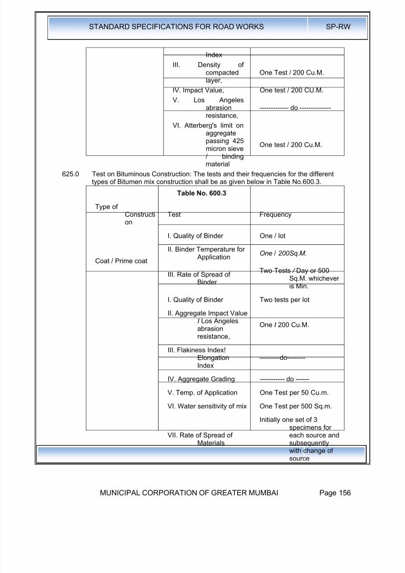
8/19/2019 MCGM Road Spec Volume -II
http://slidepdf.com/reader/full/mcgm-road-spec-volume-ii 160/176
STANDARD SPECIFICATIONS FOR ROAD WORKS SP-RW
MUNICIPAL CORPORATION OF GREATER MUMBAI Page 156
Index
III. Density ofcompactedlayer,
One Test / 200 Cu.M.
IV. Impact Value, One test / 200 CU.M.V. Los Angeles
abrasionresistance,
------------- do --------------
VI. Atterberg's limit onaggregatepassing 425micron sieve/ bindingmaterial
One test / 200 Cu.M.
625.0 Test on Bituminous Construction: The tests and their frequencies for the different
types of Bitumen mix construction shall be as given below in Table No.600.3.Table No. 600.3
Type ofConstruction
Test Frequency
Coat / Prime coat
I. Quality of Binder One / lot
II. Binder Temperature for Application
One / 200Sq.M.
III. Rate of Spread ofBinder
Two Tests / Day or 500Sq.M. whicheveris Min.
I. Quality of Binder Two tests per lot
II. Aggregate Impact ValueI Los Angelesabrasionresistance,
One I 200 Cu.M.
III. Flakiness Index!Elongation
Index
---------do--------
IV. Aggregate Grading ----------- do ------
V. Temp. of Application One Test per 50 Cu.m.
VI. Water sensitivity of mix One Test per 500 Sq.m.
VII. Rate of Spread ofMaterials
Initially one set of 3specimens foreach source andsubsequentlywith change ofsource

8/19/2019 MCGM Road Spec Volume -II
http://slidepdf.com/reader/full/mcgm-road-spec-volume-ii 161/176
STANDARD SPECIFICATIONS FOR ROAD WORKS SP-RW
MUNICIPAL CORPORATION OF GREATER MUMBAI Page 157
VIII. Soundness
Initially one determinationby each methodfor each source ,then as
warranted bychange: ofquality ofaggregate
ix. Polished stone value One for each rock type
x. Percentage of fracturedfaces
One test per day if gravelis used
xi. Stripping value ofaggregates (
immersion traytest)
Initially one set of 3specimens foreach source and
subsequentlywith change ofsource
xii. Water absorption ofaggregate
--------- do------
i. I to xii As for seal coat
xiii. Binder content andaggregategrading
One test per 500 Cu.M. ormin. two testsper day
xiv. Density of compactedlayer
One test per 250 Sq. M.
I. i to iv and vi to xiv As for B.M.
xv. sand equivalent As directed by Engineer
xvi. Plasticity index As directed by Engineer
xvii. Stability of Mix
For each 400 tonnes of mixproduced, a setof 3 Marshal
specimenstested forstability, flowvalue, densityand void contentsubject to aminimum of twosets being testedper plant per day
xviii. Swell test on mixFor B.C., as directed by
Engineer
i. i to xii As for seal coat

8/19/2019 MCGM Road Spec Volume -II
http://slidepdf.com/reader/full/mcgm-road-spec-volume-ii 162/176
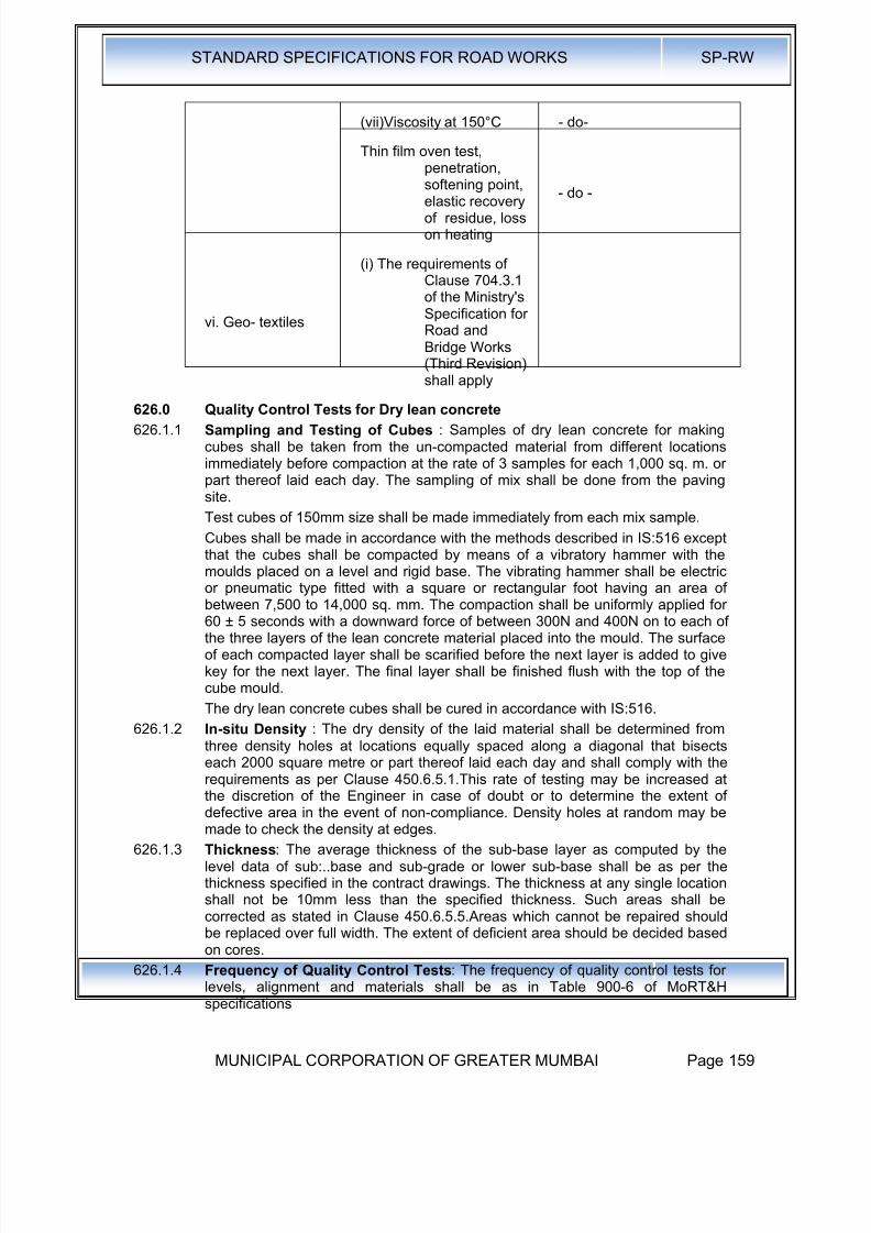
8/19/2019 MCGM Road Spec Volume -II
http://slidepdf.com/reader/full/mcgm-road-spec-volume-ii 163/176
STANDARD SPECIFICATIONS FOR ROAD WORKS SP-RW
MUNICIPAL CORPORATION OF GREATER MUMBAI Page 159
(vii)Viscosity at 150°C - do-
Thin film oven test,penetration,softening point,elastic recoveryof residue, losson heating
- do -
vi. Geo- textiles
(i) The requirements ofClause 704.3.1of the Ministry'sSpecification forRoad andBridge Works(Third Revision)shall apply
626.0 Quality Control Tests for Dry lean concrete
626.1.1 Sampling and Testing of Cubes : Samples of dry lean concrete for makingcubes shall be taken from the un-compacted material from different locationsimmediately before compaction at the rate of 3 samples for each 1,000 sq. m. orpart thereof laid each day. The sampling of mix shall be done from the pavingsite.
Test cubes of 150mm size shall be made immediately from each mix sample.
Cubes shall be made in accordance with the methods described in IS:516 exceptthat the cubes shall be compacted by means of a vibratory hammer with themoulds placed on a level and rigid base. The vibrating hammer shall be electric
or pneumatic type fitted with a square or rectangular foot having an area ofbetween 7,500 to 14,000 sq. mm. The compaction shall be uniformly applied for60 ± 5 seconds with a downward force of between 300N and 400N on to each ofthe three layers of the lean concrete material placed into the mould. The surfaceof each compacted layer shall be scarified before the next layer is added to givekey for the next layer. The final layer shall be finished flush with the top of thecube mould.
The dry lean concrete cubes shall be cured in accordance with IS:516.
626.1.2 In-situ Density : The dry density of the laid material shall be determined fromthree density holes at locations equally spaced along a diagonal that bisectseach 2000 square metre or part thereof laid each day and shall comply with the
requirements as per Clause 450.6.5.1.This rate of testing may be increased atthe discretion of the Engineer in case of doubt or to determine the extent ofdefective area in the event of non-compliance. Density holes at random may bemade to check the density at edges.
626.1.3 Thickness: The average thickness of the sub-base layer as computed by thelevel data of sub:..base and sub-grade or lower sub-base shall be as per thethickness specified in the contract drawings. The thickness at any single locationshall not be 10mm less than the specified thickness. Such areas shall becorrected as stated in Clause 450.6.5.5.Areas which cannot be repaired shouldbe replaced over full width. The extent of deficient area should be decided basedon cores.
626.1.4 Frequency of Quality Control Tests: The frequency of quality control tests forlevels, alignment and materials shall be as in Table 900-6 of MoRT&Hspecifications
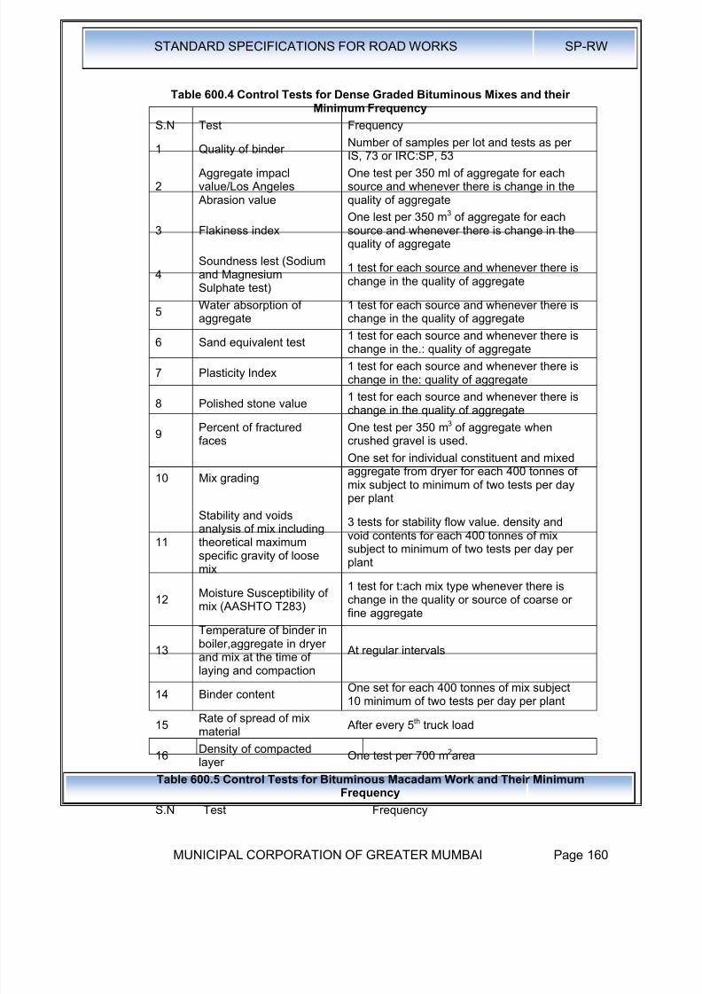
8/19/2019 MCGM Road Spec Volume -II
http://slidepdf.com/reader/full/mcgm-road-spec-volume-ii 164/176
STANDARD SPECIFICATIONS FOR ROAD WORKS SP-RW
MUNICIPAL CORPORATION OF GREATER MUMBAI Page 160
Table 600.4 Control Tests for Dense Graded Bituminous Mixes and theirMinimum Frequency
S.N Test Frequency
1 Quality of binderNumber of samples per lot and tests as per
IS, 73 or IRC:SP, 53
2 Aggregate impaclvalue/Los Angeles Abrasion value
One test per 350 ml of aggregate for eachsource and whenever there is change in thequality of aggregate
3 Flakiness indexOne lest per 350 m3 of aggregate for eachsource and whenever there is change in thequality of aggregate
4Soundness lest (Sodiumand MagnesiumSulphate test)
1 test for each source and whenever there ischange in the quality of aggregate
5
Water absorption of
aggregate
1 test for each source and whenever there is
change in the quality of aggregate
6 Sand equivalent test1 test for each source and whenever there ischange in the.: quality of aggregate
7 Plasticity Index1 test for each source and whenever there ischange in the: quality of aggregate
8 Polished stone value1 test for each source and whenever there ischange in the quality of aggregate
9Percent of fracturedfaces
One test per 350 m3 of aggregate whencrushed gravel is used.
10 Mix grading
One set for individual constituent and mixed
aggregate from dryer for each 400 tonnes ofmix subject to minimum of two tests per dayper plant
11
Stability and voidsanalysis of mix includingtheoretical maximumspecific gravity of loosemix
3 tests for stability flow value. density andvoid contents for each 400 tonnes of mixsubject to minimum of two tests per day perplant
12Moisture Susceptibility ofmix (AASHTO T283)
1 test for t:ach mix type whenever there ischange in the quality or source of coarse orfine aggregate
13Temperature of binder inboiler,aggregate in dryerand mix at the time oflaying and compaction
At regular intervals
14 Binder contentOne set for each 400 tonnes of mix subject10 minimum of two tests per day per plant
15Rate of spread of mixmaterial
After every 5th truck load
16Density of compactedlayer
One test per 700 m2area
Table 600.5 Control Tests for Bituminous Macadam Work and Their Minimum
Frequency
S.N Test Frequency
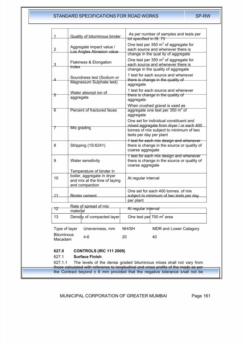
8/19/2019 MCGM Road Spec Volume -II
http://slidepdf.com/reader/full/mcgm-road-spec-volume-ii 165/176
STANDARD SPECIFICATIONS FOR ROAD WORKS SP-RW
MUNICIPAL CORPORATION OF GREATER MUMBAI Page 161
1 Quality of bituminous binder As per number of samples and tests perlot specified in IS: 73
2 Aggregate impact value /Los Angles Abrasion value
One test per 350 m3 of aggregate foreach source and whenever there is
change in the qual ity of aggregate
3Flakiness & ElongationIndex
One test per 350 m3 of aggregate foreach source and whenever there ischange in the quality of aggregate
4Soundness tesl (Sodium orMagnesium Sulphate test)
1 test for each source and wheneverthere is change in the quality ofaggregate
5Water absorpt ion ofaggregate
1 test for each source and wheneverthere is change in the quality ofaggregate
6 Percent of fractured faces
When crushed gravel is used as
aggregate one test per 350 m3 ofaggregate
7 Mix grading
One set for individual constituent andmixed aggregate from dryer / or each 400tonnes of mix subject to minimum of twotests per day per plant
8 Stripping (1S:6241)1 test for each mix design and wheneverthere is change in the source or quality ofcoarse aggregate
9 Water sensitivity1 test for each mix design and wheneverthere is change in the source or quality ofcoarse aggregate
10
Temperature of binder inboiler, aggregate in dryerand mix at the lime of layingand compaction
At regular interval
11 Binder cementOne set for each 400 tonnes. of mixsubject to minimum of two tests per dayper plant
12Rate of spread of mixmaterial
At regular interval
13 Density of compacted layer One test per 700 m
3
area
Type of layer Unevenness, mm NH/SH MDR and Lower Catagory
BituminousMacadam
4-6 20 40
627.0 CONTROLS (IRC 111 2009)
627.1 Surface Finish
627.1.1 The levels of the dense graded bituminous mixes shall not vary fromthose calculated with reference to longitudinal and cross profile of the roads as per
the Contract beyond ± 6 mm provided that the negative tolerance shall not be

8/19/2019 MCGM Road Spec Volume -II
http://slidepdf.com/reader/full/mcgm-road-spec-volume-ii 166/176
STANDARD SPECIFICATIONS FOR ROAD WORKS SP-RW
MUNICIPAL CORPORATION OF GREATER MUMBAI Page 162
permitted in conjunction with the positive tolerance for the base course if thethickness of the former is thereby reduced by more than 6 mm.
627.1.2 For checking the compliance with the above requirementmeasurements of the surface level shall be taken on a grid of points spaced 6.25
m along the length and 0.5 m from the edges and at the centre of the pavement.The compliance shall be deemed to be met for the final road surface only if thetolerance given above is satisfied for any point on the surface.
627.1.3 In case where surface levels fall outside the specified tolerance, theContractor shall be liable to rectify these by replacing the full depth of layer. In allcases of replacement the area treated shall not be less than 5 m in length and notless than 3.5 m in width.
627.2 Surface Evenness
627.2.1 The measurement and checking of surface unevenness shall be doneby a 3 m straight edge in accordance with the procedures in IRC:SP: 16.
627.2.2 The maximum permissible surface unevenness in longitudinal profile
shall be 6 mm for SDBC and 5 mm for BC. The maximum permissible unevennessin transverse profile shall be 4 mm for both SDBC and BC
627.2.3 The maximum permissible frequency of surface unevenness in 300 mlength in longitudinal profile shall be as per Table 600.3.3
627.2.4 Where the surface unevenness falls outside the tolerance, in eithercase i.e. the surface is low or high, the full depth of the layer shall be removed andreplaced with fresh material and compacted to the specification.
627.2.5 In all cases of removal and replacement the area treated shall not beless than 5 m in length and 3.5 m in width.
627.3 Surface Roughness
627.3.1 Surface roughness shall be checked in accordance with procedures in
lRC:SP: 16.627.3.2 The maximum permissible values of surface roughness measured witha bump integrator are given in Table 600.3.4. Newly constructed surface areexpected 10 give roughness values corresponding to Good category. While the Average and Poor categories indicate level of service and the intervention criteriadeviation.
627.4 Acceptance Criteria
627.4.1 The acceptance criteria for test on density (N = 3 minimum) andMarshall stability (N = 2 minimum) shall be subjected to the condition that themean value of N samples is not less than the specified value plus [1.65 - 1.65/(No.of samples)O.5] x standard
Table 600.6 Maximum Permissible Frequency of Unevenness MaximumNumber of Surface Unevenness
Type of Surfaceuneveness,
mmNH/SH
MDR andLower
Category
Semi-Dense BituminousConcrete
4-6 20 40
Bituminous Concrete 3-5 15 30
Table 600.7 Maximum Permissible Values of Roughness (mm/km) for Surfacewith Dense Graded Bituminous Mixes
S.N. Type of Surface Condition of Road Surface (mm I km)Good Average Poor

8/19/2019 MCGM Road Spec Volume -II
http://slidepdf.com/reader/full/mcgm-road-spec-volume-ii 167/176
STANDARD SPECIFICATIONS FOR ROAD WORKS SP-RW
MUNICIPAL CORPORATION OF GREATER MUMBAI Page 163
1 SDBC < 2500 2500-3500 > 3500
2 BC < 2000 2000-3000 >3000

8/19/2019 MCGM Road Spec Volume -II
http://slidepdf.com/reader/full/mcgm-road-spec-volume-ii 168/176
STANDARD SPECIFICATIONS FOR ROAD WORKS SP-RW
MUNICIPAL CORPORATION OF GREATER MUMBAI Page 164
APPENDIX-1
Quality Tests for Tack Coat and Prime Coat
In case of bitumen emulsion residue on 600 micron sieve, viscosity test andstorage stability tests shall be conducted at site. In case of cutback bitumen,viscosity test, flash point test and residue test shall be conducted at site. In case ofpaving grade bitumen, viscosity at 60°C and 160°C shall be determined.
APPENDIX - 2
Method of Test for Measurement of Spread of Binder for Prime Coat andTack Coat
Aluminum or other light metal tray of 200 mm x 200 mm size and 20 mm depth areto be used. A set of three plates is essential for one test. All the plates are to beweighed and numbered. These are placed at intervals of 10 m along the road in
path between wheels of bitumen distributor. After the distributor crosses a length of50 m, trays are to be removed and wrapped in weighed polyethylene bags so thatthese can be handled, stocked safely for further weighing in laboratory. The traysshall be weighed to first place of decimal. Similarly, transverse distribution of liquidbituminous material can be checked by placing three numbers of plates at intervalof 50 cm in the path of binder spraying equipment.

8/19/2019 MCGM Road Spec Volume -II
http://slidepdf.com/reader/full/mcgm-road-spec-volume-ii 169/176
STANDARD SPECIFICATIONS FOR ROAD WORKS SP-RW
MUNICIPAL CORPORATION OF GREATER MUMBAI Page 165
ANNEXURE 1Features of Hot Mix Plants & Pavers for Bituminous Construction:Hot mix plant shall be of suitable capacity preferably of batch mix type. Total system
for crushing of stone aggregates arid feeding of aggregate fractions in requiredproportions to achieve the desired mix, must be capable of meeting the overallspecification requirements under stringent quality control.The plant shall have the following essential features:
A Generala) The plant shall have a coordinated set of essential units capable of producinguniform mix as per the job mix formula.b) Cold aggregate feed system with minimum 4 bins having bell conveyorarrangement for initial proportioning of aggregates from each bin in the requiredquantities. In order to have free flow of fines from the bin, bin should be titled withvibrator to intermittently shake it.c) Belt conveyers below each bin should have variable speed drive motors. Thereshould be electronic load sensor on the main conveyer for measuring the flow ofaggregates.d) Dryer unit with burner capable of heating the aggregate to the requiredtemperature without any visible unburnt fuel or carbon residue on the aggregate andreducing the moisture con lent of the aggregate to the specified minimum.e) The plant shall be fitted with suitable type of thermometric instruments atappropriate places so as to indicate or record/register the temperature of healedaggregate, bitumen and mix.f) Bitumen supply unit capable of heating, measuring/metering and spraying ofbitumen at specific temperature with automatic synchronization of bitumen and
aggregate feed in the required proportion.g) A filler system suitable to receive bagged or bulk supply of filler material and itsincorporation to the mix in the correct quantity wherever required.h) A suitable built-in dust control system for the dryer to contain/recycle permissiblefines into the mix. It should be capable of preventing the exhaust of fine dust intoatmosphere for environmental control wherever so specified by the Engineer.i) The plant- should have centralized control panel cabin capable of presetting,controlling / synchronizing all operations stating from feeding of cold aggregates tothe discharge of the hot mix to ensure proper quality of mix. It should haveindicators for any malfunClionit1g in the operation. j) Every hot mix plant should be equipped with siren or horn so that the operatormay use the same before starting the plant every time in the interest of safety of
staff.
B For Batch Type Planti) Gradation control unit having minimum four decks vibratory screens for accuratesizing of hot aggregate and storing them in separate bins. This unit should be fullycovered to reduce the maintenance cost and for better environmental condition.ii) Proper arrangement for accurate weighing of each size of hot aggregate from thecontrol panel before mixing.iii) Paddle mixer unit shall be capable of producing a homogeneous mix with uniformcoating of all particles or the mineral aggregate-with binder
C For Continuous Type Plant

8/19/2019 MCGM Road Spec Volume -II
http://slidepdf.com/reader/full/mcgm-road-spec-volume-ii 170/176
STANDARD SPECIFICATIONS FOR ROAD WORKS SP-RW
MUNICIPAL CORPORATION OF GREATER MUMBAI Page 166
i) Gradation control unit having vibratory screens for accurate sizing of hotaggregate and storing them in separate bins. This unit should be fully covered toreduce the maintenance cost and for better environmental condition.ii) There should be appropriate arrangement for regulating and volumetric conditionof the flow of hot aggregate from each bin to achieve the required proportioning.iii) Paddle mixer unit shall be capable of producing a homogeneous mix with uniformcoating of all particles of the mineral aggregate with binder.
D For Drum Mix Planti) It is a prerequisite that only properly screened and graded materials are fed to thebins. If required, a vibratory screening unit shall be installed at the plant site toensure the same. A primary 4-deck vibratory screening unit shall be installed beforethe multiple bin cold feed system for screening the aggregates and grading thesame.ii) Belt conveyers below each bin should have variable speed drive motors. Thereshould be electronic' load sensor on the main conveyer for measuring the flow of
aggregate.iii) There should be arrangement to measure moisture content of the aggregate(s)so that moisture correction may be applied for working out requirements of binderand filler.
E . Paver FinisherThe paver finisher shall have the following essential features:a) Loading hoppers and suitable distributing mechanism.b) All drives having hydrostatic drive/control.c) The machine shall have a hydraulically extendable screed for appropriate withrequirement.d) The screed shall have tamping and vibrating arrangement for initial compaction to
the layer as it is spread without rutting or otherwise marring the surface. It shall haveadjustable amplitude and variable frequency.e) The paver shall be equipped with necessary control mechanism so as to ensurethat the finished surface is free from surface blemishes.f) The paver shall be fitted with an electronic sensing device for automatic levellingand profile control within the specified tolerances.g) The screed shall have an internal heating arrangement.h) The paver shall be capable of laying either 2.5 to 4.0 m width or 4.0 to 7.0 mwidth as stipulated in the Contract.
i) The paver shall be so designed as to eliminate skidding/slippage of the tyresduring operations.

8/19/2019 MCGM Road Spec Volume -II
http://slidepdf.com/reader/full/mcgm-road-spec-volume-ii 171/176
STANDARD SPECIFICATIONS FOR ROAD WORKS SP-RW
MUNICIPAL CORPORATION OF GREATER MUMBAI Page 167
ANNEXURE 2
Outline of AASHTO T283, "Resistance of Compacted Asphalt Mixtures toMoisture-Induced Damage"
A. Scope and Summary of Test Method
This method covers preparation of compacted bituminous mixtures and themeasurement of the change of diametral tensile strength resulting from the effectsof water saturation and laboratory accelerated stripping phenomenon with afreeze-thaw cycle. The result may be used to predict long-term strippingsusceptibility of bituminous mixtures and evaluate liquid anti-stripping additives thatare added to bitumen or pulverized mineral materials such as hydrated lime, whichare added to the mineral aggregate.
Each Set of 6 compacted specimens is divided into two equal subsets. One subsetis tested in dry condition for indirect tensile strength. The other subset is subjectedto vacuum saturation and a freeze-thaw cycle (thawing in a hot water bath) beforetesting for indirect tensile strength. Numerical indices of retained indirect tensilestrength properties are calculated from the test data obtained by testing the twosubsets :dry and conditioned.
B. Testing Equipment
I. Vacuum container, vacuum pump, manometer, and other accessories asspecified in ASTM D2041, "Theoretical Maximum Specific Gravity and Density ofBituminous Paving Mixtures".
2. Balance or scale accurate to 0.1 percent of the test load
3. Two water baths capable of maintaining temperatures of 60°C ± 1°C and 25°C ±0.5°C
4. Freezer maintained at - 18°C ± 3°C5. 10-ml graduate cylinder
6. Loading jack ,and ring dynamometer (Marshall stability testing machine can beused) to provide a vertical rate of deformation of 50 mm (2 inches) per minute andcapable of reading the maximum failure load
7. Steel loading Strips with a concave surface having a radius equal to the normalradius of the test specimen. The loading strips shall be 12.7 mm (0.5 inch) wide forspecimens 100 mm (4 inches) in diameter. The loading strips for 150 mm (6inches) diameter specimens shall be 19.05 mm (0.75 inch) wide. The length of theloading strips shall exceed the thickness of the specimens. Steel strip are providedat the top and bottom of specimens during indirect tensile testing.
C. Test Procedure1. Make at least 6 compacted specimens for each mixture. 3 to be tested dry and 3to be tested after partial saturation and moisture conditioning with a freeze-thawcycle. Some extra specimens will need to be made 10 establish compactionprocedures in order to obtain specified air void contents in the test specimens bytrial and error.
2. Compact the 6 specimens with a Marshall compactor so that the compactedspecimens have air voids of 7.0 ± 0.5 percent. This level of high air voids can beobtained by adjusting the number of Marshall blows applied on each side of thespecimen by trial and error (start at about 10 blows as a starting point). Air voidcontent must be calculated from the bulk specific gravity of the compacted
specimen (determined by saturated surface dry method as per procedure given in

8/19/2019 MCGM Road Spec Volume -II
http://slidepdf.com/reader/full/mcgm-road-spec-volume-ii 172/176
STANDARD SPECIFICATIONS FOR ROAD WORKS SP-RW
MUNICIPAL CORPORATION OF GREATER MUMBAI Page 168
the Asphalt Institute MS-2) and the maximum theoretical specific gravity of theloose bituminous mixture obtained by ASTM D2041.
3. Separate the 6 specimens into 2 subsets so that the average air voids of the twosubsets are approximately equal.
4. One set will be tested dry. Keep it at room temperature and then place in a 250
C± 0.50C water bath for 2 hours prior to determining their indirect tensile strength.
5. The other subset will be conditioned as follows:
a) Place and submerge the 3 specimens in the vacuum container filled with waterat room temperature. Apply a vacuum of 13-67 kPa absolute pressure (10-26inches Hg partial pressure) for 30 minutes. Remove the vacuum and leave thespecimens submerged in water for 5 to 10 minutes. [Note: The water saturationprocedure noted above deviates from AASHTO T283, which obtains a specifieddegree of saturation. The above procedure keeps the time of saturation constant:
b) Wrap a plastic film around each saturated specimen and place the wrappedspecimen in a plastic bag containing 10 ml of water and seal the plastic bag. Place
the plastic bag in a freezer at temperature of - 180
C± 30C for a minimum of 16hours. Remove the specimens from the freezer.
c) Place the specimens in a water bath maintained at 60 0C ± 10C for 24 hours.Remove the plastic bag and the plastic film from each specimen after placing thespecimens under water.
d) . Remove the specimens from hot water bath and place in a water bathmaintained at 250C ± 0.50C for 2 hours
e) Remove the conditioned specimens and test for indirect tensile strength.
6. Determine the indirect tensile strength of the 3 dry and 3 conditioned specimensat 250C ± 0.50C after removing from water bath. First, measure their meanthicknesses (t). Then place the two steel loading strips on the bottom and top of
the specimens across diameter and place in the Marshall testing machine or acompression testing machine. Apply load to the specimens diametrally at a verticalrate of 50 mm (2 inches) per minute.
7. Record the maximum compressive strength noted on the testing machine andcontinue loading until a vertical crack appears in the specimen. Remove thecracked specimen from the machine and visually estimate the approximate degreeof moisture damage (extent of stripped or bare aggregate) on the fractured faces ofthe specimen on a scale of 0 to 5 (5 being the most stripping).
8. Calculate the tensile strength of each specimen as follows in SI units:
St = 2000 P/¶td
Where,
st= tensile strength. kPa
P = maximum loads, N
t = specimen-thickness, mm
d = specimen diameter. mm
9. Express the numerical index of resistance of bituminous mixture to thedetrimental effects of water as the ratio of the original strength that is retained afteraccelerated moisture and freeze-thaw conditioning.
Calculate the tensile strength ratio (TSR) as follows:
Tensile strength ratio (TSR) =S2/S1
Where.
S1 = average tensile strength of the dry subset. kPa

8/19/2019 MCGM Road Spec Volume -II
http://slidepdf.com/reader/full/mcgm-road-spec-volume-ii 173/176
STANDARD SPECIFICATIONS FOR ROAD WORKS SP-RW
MUNICIPAL CORPORATION OF GREATER MUMBAI Page 169
S2 = average tensile strength of the conditioned subset, kPa

8/19/2019 MCGM Road Spec Volume -II
http://slidepdf.com/reader/full/mcgm-road-spec-volume-ii 174/176
STANDARD SPECIFICATIONS FOR ROAD WORKS SP-RW
MUNICIPAL CORPORATION OF GREATER MUMBAI Page 170
ANNEXURE 3
Outline of ASTM D2041, "Theoretical Maximum Specific Gravity and Densityof Bituminous Paving Mixtures"
A. Scope and Summary of the Test Method
This test method covers the determination of the theoretical maximum specificgravity and density of uncompacted bituminous paving mixtures at 25 °C. Thetheoretical maximum specific gravity (Gmm) is used: (a) 10 calculate air voids incompacted bituminous mixtures. (b) to calculate the amount of bitumen absorbedby the aggregate, and (e) to provide target value for the compaction of pavingmixtures in the field.
A sample of loose paving mixture is placed in a tared vacuum vessel. Water at25°C is added to complete ly submerge the sample. A specified amount of vacuumis gradually applied to remove the air bubbles entrapped between asphalt mixparticles. After the vacuum is released, the volume of the sample of the void lesspaving mixture is obtained by either immersing the vacuum container with the
sample in a water bath and weighing or by filling the calibrated vacuum containerlevel full of water and weighing in air.
B. Testing Equipment
1. Container (either a or b below)
a) Vacuum bowls - Either a metal or plastic bowl with a diameter ranging from 18010260 mm and a bowl height of at least 160 mm. The bowl shall be equippedwith a stiff, transparent cover fitted with a rubber gasket and a connection forthe vacuum line. The hose connection shall be covered with a small piece offine wire mesh to minimize loss of any fine material from the mix.
b) Vacuum flask for weighing in air only - A thick-walled volumetric glass flaskwith a capacity of approx. 4000 ml, fitted with a rubber stopper with a connection for the vacuum line. The hose connection shall be covered with a smallpiece of fine wire mesh to minimize loss of any fine material from the mix .
2.Balance capable of being read to the nearest 0.1 gram. If weighing is to be doneunder water. a suitable suspension arrangement shall be provided for weighingthe sample while suspended from the center of the balance.
3. Vacuum pump, capable of excavating air from the vacuum container to aresidual pressure of 4.0 kPa (30 mm of Hg) or less. Provide a suitable trapbetween the pump and container to minimize water vapour entering thevacuum pump
4. Residual pressure manometer or calibrated absolute pressure gauge with ableed valve to adjust the vacuum level.
5. Water bath capable of maintaining a constant temperature of 25 ± 1°C andsuitable for immersion of the suspended container.
C. Calibration of Containers
1. Bowls - Determine the mass (B) of the container immersed in water at 25 ± 1 0C.If the bowl is used for weighing in air place the volumetric lid on the bowl whileunder water. Remove the water-filled bowl with the lid in place and dry prior todetermining the combined mass of the bowl, lid and water. Repeat 3 times andaverage the 3 masses. Designate the average mass as D.
2. Flasks - Calibrate the volumetric flask by accurately determining the mass of theflask filled with water at 25 ± 1°Co Use a glass cover plate to ensure the flask is
completely full.D. Test Procedure
8/19/2019 MCGM Road Spec Volume -II
http://slidepdf.com/reader/full/mcgm-road-spec-volume-ii 175/176
STANDARD SPECIFICATIONS FOR ROAD WORKS SP-RW
MUNICIPAL CORPORATION OF GREATER MUMBAI Page 171
I. Separate the particles of the loose paving mixture (while it is warm) by hand sothat the particles are not larger than about 6 mm. Don't fracture the aggregate.Place the mix sample directly into the tared bowl or flask. Weigh the containerwith the sample and designate the net mass of the sample only as A.[Note: Theminimum sample size shall be 1500g for mixes with nominal maximumaggregate sizes of 12.5 mm or smaller; and shall be 2500g for mixes withnominal maximum aggregate sizes from 19 to 25 mm]
2. Add sufficient water at 25°C to cover the sample completely. Place the cover(bowls) or stopper (flasks) on the containers.
3. Place the container with the sample and water on a mechanical agitation deviceor agitate manually at frequent intervals (2 to 3 minutes). Begin removingentrapped air by gradually applying vacuum and increasing the vacuumpressure until the residual manometer reads 3.7 ± 0.3 kPa (27.5 ± 2.5 mm ofHg). After achieving this level within 2 minutes, continue the vacuum andagitation for 15 ± 2 minutes. Gradually release the vacuum with the bleed valve.
4. Weighing in water - Suspend the bowl (without lid) and contents in water for 10 ±
1 minutes and then determine mass. Designate the mass under water of thebowl and sample as °C
5. Weighing in air
a) Bowl- Submerge the bowl and sample slowly in the 25 ± 1°C water bath. Keep itthere for 10 ± 1 minutes. Immerse the lid in water and slide it onto the bowlwithout removing
water from the bowl so that no ai r is trapped inside the bowl.Remove the bowl with the lid in place from the water bath. Dry the bowl and lidwith a dry cloth. Determine the mass of the bowl, sample, and lid and designateit as E.
b) Flask - Fill the flask slowly with water ensuring not to introduce any air into thesample. Place the flask in water bath for 10 ± 1 minutes to stabilize the
temperature aI 25°C without submerging the top of the flask. Completely fill theflask with water using a cover plate without entrapping air beneath the coverplate. Wipe the exterior of the fl ask and cover plate. Determine the mass of theflask, plate and its contents completely filled with water. Designate this mass asE.
6. Calculations
Calculate the maximum specific gravity of the sample of loose paving mixure asfollows:
a) Bowls Used Under Water Determination:
Gmm.=A / [A-(C-B)]
Where,Gmm = maximum specific gravity of the mixture
A = mass of the dry sample in air. g
B = mass of bowl under water, g
C = mass of bowl and sample under water, g
b) Bowls in Air Determination:
Gmm.=A / (A+D-E)
Where,
Gmm = maximum specific gravity of the mixture
A = mass of the dry sample in air. g
D = mass of lid and bowl with water at 25°C, g
8/19/2019 MCGM Road Spec Volume -II
http://slidepdf.com/reader/full/mcgm-road-spec-volume-ii 176/176
STANDARD SPECIFICATIONS FOR ROAD WORKS SP-RW
E = mass of lid, bowl, sample and water at 25°C, ,g
c) Flask Determination
Gmm.=A / (A+D-E)
Where,
Gmm = maximum specific gravity of the mixture
A = mass of the dry sample in air. g
D = mass of cover plate and flask filled with water at 25°C. g
E = mass of flask, cover plate, sample. and water at 25°C, ,g