Material compuesto en base Bioglass Polivinil fiber
9
Available online at www.sciencedirect.com ScienceDirect Journal of the European Ceramic Society 34 (2014) 3379–3387 Preparation and characterization of Bioglass ® -based scaffolds reinforced by poly-vinyl alcohol/microfibrillated cellulose composite coating L. Bertolla a,∗ , I. Dlouh´ y a , A.R. Boccaccini b a Institute of Physics of Materials ASCR, CEITEC IPM, ˇ Ziˇ zkova 22, 61662 Brno, Czech Republic b Institute of Biomaterials, Department of Materials Science and Engineering, University of Erlangen-Nuremberg, 91058 Erlangen, Germany Available online 1 May 2014 Abstract The present work deals with the preparation and mechanical characterization of Bioglass ® -based porous scaffolds reinforced by a composite coating constituted by polyvinyl alcohol (PVA) and microfibrillated cellulose (MFC). Samples were produced by foam replication process, using a novel ethanol-based Bioglass ® slurry. The addition of PVA/MFC coating led to a 10 fold increase of compressive strength and a 20 fold increase of tensile strength in comparison with non-coated scaffolds. SEM observations of broken struts surfaces proved the reinforcing and toughening effect of the composite coating which were ascribed to crack bridging and fracture of cellulose fibrils. The mechanical properties of the coatings were investigated by tensile testing of PVA/MFC composite stripes. The stirring time of the PVA/MFC solution came out as a crucial parameter in order to achieve a more homogeneous dispersion of the fibers and therefore enhanced strength and stiffness. © 2014 Elsevier Ltd. All rights reserved. Keywords: Bioceramics; Bioglass ® scaffolds; Porous materials; Polymer coating; Composite coating 1. Introduction For more than 30 years, bioactive glasses have been com- mercially available, being used in form of particles or granules as bone substituting material in orthopedic applications 1 and in dentistry surgeries. 2 The main drawback still impairing the use of bioactive glasses in load-bearing applications is their intrin- sic brittleness. This aspect becomes even more critical when these materials are used in form of highly porous scaffolds, 3 e.g. for bone tissue engineering applications, making very dif- ficult their handling during surgical procedures and facing a high probability of failure after surgery. The deposition of a thin polymeric coating on bioactive ceramic/glass scaffolds in order to increase their fracture strength and crack resistance is an effective method which has been already reported by several researchers. 4,5 As cracks nucleate and propagate across the struts under the influence of a local component of applied external load, the coating film undergoes progressive deformation forming thin ∗ Corresponding author. Tel.: +420 608238919. E-mail addresses: [email protected], [email protected] (L. Bertolla). fibrils which are capable to bridge the cracks edges, opposing the crack opening process and preventing the catastrophic fracture of the whole structure. 5,6 Deformation and tearing of coating fib- rils are responsible for energy dissipation, causing an increase of the overall fracture energy. This phenomenon corresponds to the plateau region which is usually observable on the load displace- ment curves from tensile and compressive strength tests. 6 So far, different polymers, either natural or synthetic have been used for this purpose. Among the natural ones, collagen, 7 alginate, 8 silk, 9 gelatin 10 and chitosan 11 can be mentioned. Concerning the synthetic ones, poly(lactic acid), 12 poly(hydroxybutyrate), 13 PHBV, 14 poly(-caprolactone) 15 were reported as well. Besides sufficient mechanical capability, coatings for bone replacement scaffolds must also fulfill other requirements such as biocompatibility, biodegradability and tunable degra- dation rate. The possibility of functionalization of scaffolds for controlled drug release is also a desirable goal. 8,11,14 Unfor- tunately, polymers usually exhibit low elastic modulus (below a few GPa), therefore it is desirable to develop improved biodegradable coatings having higher elastic modulus, tensile strength, and toughness. Polyvinyl alcohol (PVA) is a water- soluble biodegradable and non-toxic polymer which is gaining http://dx.doi.org/10.1016/j.jeurceramsoc.2014.04.003 0955-2219/© 2014 Elsevier Ltd. All rights reserved.
description
Biomaterials
Transcript of Material compuesto en base Bioglass Polivinil fiber
A
Tcaoewi©
K
1
madostefihtoarut
h0
Available online at www.sciencedirect.com
ScienceDirect
Journal of the European Ceramic Society 34 (2014) 3379–3387
Preparation and characterization of Bioglass®-based scaffolds reinforced bypoly-vinyl alcohol/microfibrillated cellulose composite coating
L. Bertolla a,∗, I. Dlouhy a, A.R. Boccaccini b
a Institute of Physics of Materials ASCR, CEITEC IPM, Zizkova 22, 61662 Brno, Czech Republicb Institute of Biomaterials, Department of Materials Science and Engineering, University of Erlangen-Nuremberg, 91058 Erlangen, Germany
Available online 1 May 2014
bstract
he present work deals with the preparation and mechanical characterization of Bioglass®-based porous scaffolds reinforced by a compositeoating constituted by polyvinyl alcohol (PVA) and microfibrillated cellulose (MFC). Samples were produced by foam replication process, using
novel ethanol-based Bioglass® slurry. The addition of PVA/MFC coating led to a 10 fold increase of compressive strength and a 20 fold increasef tensile strength in comparison with non-coated scaffolds. SEM observations of broken struts surfaces proved the reinforcing and tougheningffect of the composite coating which were ascribed to crack bridging and fracture of cellulose fibrils. The mechanical properties of the coatingsere investigated by tensile testing of PVA/MFC composite stripes. The stirring time of the PVA/MFC solution came out as a crucial parameter
n order to achieve a more homogeneous dispersion of the fibers and therefore enhanced strength and stiffness. 2014 Elsevier Ltd. All rights reserved.
eywords: Bioceramics; Bioglass® scaffolds; Porous materials; Polymer coating; Composite coating
ficortpmdfstP
rs
. Introduction
For more than 30 years, bioactive glasses have been com-ercially available, being used in form of particles or granules
s bone substituting material in orthopedic applications1 and inentistry surgeries.2 The main drawback still impairing the usef bioactive glasses in load-bearing applications is their intrin-ic brittleness. This aspect becomes even more critical whenhese materials are used in form of highly porous scaffolds,3
.g. for bone tissue engineering applications, making very dif-cult their handling during surgical procedures and facing aigh probability of failure after surgery. The deposition of ahin polymeric coating on bioactive ceramic/glass scaffolds inrder to increase their fracture strength and crack resistance isn effective method which has been already reported by several
4,5
esearchers. As cracks nucleate and propagate across the strutsnder the influence of a local component of applied external load,he coating film undergoes progressive deformation forming thin∗ Corresponding author. Tel.: +420 608238919.E-mail addresses: [email protected], [email protected] (L. Bertolla).
dctabss
ttp://dx.doi.org/10.1016/j.jeurceramsoc.2014.04.003955-2219/© 2014 Elsevier Ltd. All rights reserved.
brils which are capable to bridge the cracks edges, opposing therack opening process and preventing the catastrophic fracturef the whole structure.5,6 Deformation and tearing of coating fib-ils are responsible for energy dissipation, causing an increase ofhe overall fracture energy. This phenomenon corresponds to thelateau region which is usually observable on the load displace-ent curves from tensile and compressive strength tests.6 So far,
ifferent polymers, either natural or synthetic have been usedor this purpose. Among the natural ones, collagen,7 alginate,8
ilk,9 gelatin10 and chitosan11 can be mentioned. Concerninghe synthetic ones, poly(lactic acid),12 poly(hydroxybutyrate),13
HBV,14 poly(�-caprolactone)15 were reported as well.Besides sufficient mechanical capability, coatings for bone
eplacement scaffolds must also fulfill other requirementsuch as biocompatibility, biodegradability and tunable degra-ation rate. The possibility of functionalization of scaffolds forontrolled drug release is also a desirable goal.8,11,14 Unfor-unately, polymers usually exhibit low elastic modulus (below
few GPa), therefore it is desirable to develop improved
iodegradable coatings having higher elastic modulus, tensiletrength, and toughness. Polyvinyl alcohol (PVA) is a water-oluble biodegradable and non-toxic polymer which is gaining
3 ean C
gtsdhdas
ctfinaahbhfibespfacpAade
2
B2i≤sscMGtBorpffdaiswb
cdottdMrortboa2ttfmes
b
P
w2(c
P
w
ρ
wac
ρ
wMa
nsmsaia
380 L. Bertolla et al. / Journal of the Europ
rowing interest for biomedical applications both as a struc-ural component, e.g. for artificial cartilage or tissue engineeringcaffolds16 or as a functional component, e.g. for controlled drugelivery systems.17 Cellulose is a linear, high-molecular-weightydrophilic polysaccharide consisting of repeating poly-�(1,4)--glucopranose units. It naturally occurs in plant cell walls as
load-bearing component as well as in tunicate sea animals orynthesized by bacteria.18
Microfibrillated cellulose (MFC) consists of high aspect ratioellulose nanofibrils obtained either by mechanical disintegra-ion or by acid hydrolysis19 of the wood cell wall. MFC wasrst prepared by Herrick et al. in 1983.20 Properties such ason-toxicity, biodegradability, large surface area and remark-bly high elastic modulus (∼146 GPa21) render this material
suitable reinforcing agent for biocoatings. In spite of itsydrophilicity, different surface modification processes haveeen explored, enabling the combination of MFC also withydrophobic polymers.22 The remarkable improvement of PVAlms mechanical properties by addition of cellulose fibers haseen extensively reported in several investigations.23,24 How-ver, MFC has only recently started to be considered as auitable coating for bioactive glass scaffolds.25 Starting fromrevious studies,26,27 a reinforcing coating for Bioglass® scaf-olds based on the PVA/MFC system was produced by a simplend straightforward process, without the need of additionalhemical modifications. The desired MFC content in the com-osite was obtained by tailoring the PVA solution concentration.s PVA/MFC system has been never considered before as
reinforcing coating for bioactive glass scaffolds, the oneseveloped in the present study are new candidates for bonengineering applications.
. Experimental
Commercially available bioactive glass powder (45S5ioglass® composition: 45 wt.% SiO2, 24.5 wt.% CaO,4.5 wt.% Na2O%, 6 wt.% P2O5, Schott AG, Germany) hav-ng average particle size of 4 �m (d50: (4.0 ± 1.0) �m d95:20 �m) was used in this investigation. A novel ethanol-based
lurry was prepared, in contrast to the Bioglass® water-basedlurries commonly reported in literature.3 Poly(vinyl butyral-o-vinyl alcohol-co-vinyl acetate) (PVHB), having average
w = 170.000–250.000, supplied by Sigma Aldrich ChemiembH (Germany) was used as binder. 0.7 g of PVB were added
o 50 ml of ethanol and stirred at 50 ◦C and 500 rpm for 1 h.ioglass® powder was then added to the solution in order tobtain a slurry having solid mass fraction of 30 wt.%. A fullyeticulated polyurethane foam (Eurofoam, Germany) having 45ores per linear inch (PPI) was used as sacrificial templateor the foam replication method. The foam was supplied inorm of 16 mm thick panels and then cut into cubes havingimension of 13 mm × 13 mm × 13 mm for compressive testsnd 5 mm × 10 mm × 20 mm for tensile tests. The pieces were
mmersed in the slurry for 10 s and then retrieved. The excesslurry was manually squeezed out and resulting green bodiesere dried in ventilated oven at 60 ◦C for 1 h. The ethanol-ased slurry allowed a much quicker drying of specimens inbemi
eramic Society 34 (2014) 3379–3387
omparison with those fabricated by water-based slurry. Theipping and drying procedure was repeated once again inrder to ensure a homogenous covering of the polyurethaneemplate. Samples were then sintered at 1050 ◦C for 1 h. Forhe preparation of composite coatings, fully hydrolyzed PVA,
= 1.269 g/cm3 (Sigma Aldrich Chemie GmbH, Germany) andFC gel, with 2% fibers content were used. The process was car-
ied out in two steps. First, 1 g of PVA was dissolved into 50 mlf water at 90 ◦C by vigorous stirring for 1 h. The MFC gel (cor-esponding to the desired amount of dry fibers) was then added tohe PVA water-solution. Following this procedure, two differentatches were produced, containing respectively 5 and 10 wt.%f MFC. The derived coating will be referred as PVA/5%MFCnd PVA/10%MFC. All the mixtures PVA/MFC were stirred for
h, ultrasonicated for 30 min and stirred again for 3 h at roomemperature. Scaffolds were soaked into the mixture for 5 min,hen manually retrieved and dried in a ventilated oven at 50 ◦Cor 24 h. Pure PVA-coated scaffolds were also produced for aatter of comparison. Soaking was repeated twice in order to
nsure the formation of a continuous coating film all along thetruts surface.
The porosity of each scaffolds before coating was calculatedy means of geometrical weight–volume measurements as:
=(
1 − ρs
ρb
)× 100
here ρb is the density of the bulk Bioglass® (assumed.7 g/cm3 3) and ρs is the apparent density of the scaffoldweight/volume ratio). The porosity of coated samples was cal-ulated by the modified relationship:
=(
1 − ρs
ρb
− ρcm
ρct
)× 100
here ρcm is the coating density calculated for each sample as:
cm = wf − wi
V
i and wf are respectively the weight of the scaffold before andfter coating and V is the scaffold’s volume. ρct is the theoreticaloating density calculated by the mixture rule as:
ct = XMFCρMFC + XPVAρPVA
here XMFC and XPVA are respectively the mass fractions ofFC and PVA and ρMFC and ρPVA are their densities. ρMFC is
ssumed equal to 1.14 g/cm3 from Ref. 28.A quantitative assessment of pores size and struts thick-
ess distribution was carried out by image analysis (ImageJoftware) on low magnification pictures obtained by opticalicroscopy (Stereomicroscope Olympus Z61). The cells and
truts of interest were manually selected and their mean diameternd thickness were measured. This procedure was accomplishedn order to exclude all the eventual errors which might arise from
two-dimensional projection of a three-dimensional structure,
y taking into account just the foreground and suitably orientedlements. In order to perform a reliable statistical sampling,ore than 250 cells and struts were analyzed, from differentmages.

ean Ceramic Society 34 (2014) 3379–3387 3381
ctatCumucetose5
pwmtlufictnfiM
mutsbtpa(G
3
3
saashswoFr
Table 1Average porosity values of non-coated and coated scaffolds.
No coating PVA-coating PVA/5%MFC PVA/10%MFC
9
vsbstum5efscpt
bsmapimadtpid
3
ccstaplddineirc
L. Bertolla et al. / Journal of the Europ
The mechanical performance of the Bioglass® scaffold withomposite coating was evaluated either by compressive andensile tests. Compressive tests were carried out by usingn Instron8862 (Instron®, U.S.) uniaxial machine with elec-romechanical actuator and integrated with BlueHill® software.ross-head speed of 0.5 mm/min and 100 kN load cell weresed. Concerning tensile tests, Z050 uniaxial screw-driven loadachine (Zwick GmbH, Germany) with 1 kN load cell was
sed applying a cross-head speed of 0.5 mm/min. Digital imageorrelation technique (Dantec, Germany) for sample surfacelongation measurements was used. The samples designed forensile test were glued to custom-made aluminum caps by meansf a low-shrinkage adhesive resin. Further details for tensile testamples preparation and the testing methodology can be foundlsewhere.29 All samples were conditioned in a drying oven at0 ◦C for 24 h before testing.
By following the same processing route used for coatingsreparation, pure PVA, PVA/5%MFC and PVA/10%MFC filmsere obtained by casting the mixture in a custom-made Teflon®
old. After drying for 24 h in ventilated oven at 50 ◦C, a con-inuous translucent film was formed and stripes having 50 mmength and 35 mm width were manually cut to be tested underniaxial tension. In the particular case of the PVA/10%MFClm, samples were also produced from mixtures having the sameomposition but stirred for different time (24 and 48 h), in ordero assess whether the mixing time may influence the homoge-eous dispersion of the MFC fibers in the resulting compositelms. Thickness and width of the stripes were measured by aitutoyo IP56 digital micrometer (0.01 mm resolution).For the tensile test of film stripes, a microforce testing
achine TytronTM250 (MTS®, U.S.) with 200 N load cell wassed. Pneumatic grips having rubber surface were used in ordero ensure the necessary clamping strength during deformation ofamples without damaging their surface. The strain was definedy the clamp displacement relatively to the initial distance, andhe Young modulus was obtained as the slope in the initial linearart of the stress–strain curve. The fracture surfaces of scaffoldsnd films were both analyzed by scanning electron microscopeLyra3, Tescan, Czech Republic; FEG-SEM Zeiss Ultra Plus,ermany).
. Results and discussion
.1. Scaffolds structure
The structures of scaffolds obtained by an ethanol-basedlurry and water-based slurry are respectively shown in Fig. 1and b. In both case, the template PPI, the number of dipping,nd the slurry solid fraction were the same. Nevertheless, thecaffolds produced by the ethanol-based slurry exhibited muchigher degree of interconnection and open porosity. The lowerurface tension of ethanol likely results in a slurry with better
ettability toward the PU surface and the unwanted formationf liquid membranes between the template struts is prevented.urthermore, another interesting phenomenon was observed: theeversible swelling of PU template caused by ethanol, inducesdtfc
2.51 ± 0.50 90.22 ± 0.56 90.38 ± 1.49 91.39 ± 1.59
olumetric expansion of the cells, easing the infiltration of thelurry into the inner cells of the template. Even if the ethanol-ased slurry process may have not been optimized in the presenttudy, it is important to note that these favorable aspects enablehe production of foams having constant cell geometry andniform strut thickness. Mean cells size and struts thicknesseasured by Image analysis resulted respectively as 500 �m and
0 �m. (Fig. 1c and d). Recent modeling works based on finitelement analysis refer to these two characteristics as beneficialor the strength of reticulated ceramics.30 More specifically, thetress analysis showed that compression stresses tend to con-entrate on the thinner struts. Therefore, the optimization of therocessing route in order to minimize the distribution of strutshickness is a desired goal.
As reported in several works dealing with scaffolds forone replacement,3,5 the achievement of a highly open poroustructure is one of the crucial requirements in order to ensureigration of cells and exchange of ions between the scaffold
nd the surrounding biological environment, and therefore toromote the bioactivity.3 A sufficient degree of open porositys also beneficial for a more effective penetration of the poly-er coating along the struts surface.5 The increase of weight
fter coating was slightly higher for PVA-coated samples andecreased for PVA/MFC coated samples. In Table 1 are reportedhe average porosity values calculated for all the samples. It isossible to observe that the decrease of porosity after the coat-ng procedure is almost negligible, indicating a homogenousistribution of coating along the struts surface.
.2. Scaffolds response to compressive load
Four characteristic compressive stress–strain curves for non-oated, PVA-coated, PVA/5%MFC-coated and PVA/10%MFC-oated scaffolds, respectively, are shown in Fig. 1a. Non-coatedamples turn out to be extremely brittle and weak. First frac-ure events (most probably struts fracture) are recorded as thepplied stress reaches approximately 0.05 MPa. Beyond thisoint, the deformation proceeds without further increase ofoad and progressive crushing of all the struts occurs up to theensification stage. The reduced struts thickness and surfaceefects, which are inherently associated with the manufactur-ng procedure, explain the poor mechanical capability of theon-coated scaffolds reported in this work. The coated samplesxhibit demonstrably different mechanical behavior in compar-son to non-coated ones: the first fracture events take place at aemarkably higher load (at least of one order of magnitude) inomparison with non-coated samples and they are followed by arastic drop of load. The explanation for this behavior could be
hat PVA infiltrates and fills surface defects and cracks derivedrom the sintering process, suppressing them to act as stress con-entrators and crack initiators. Beyond this point, a plateau stage
3382 L. Bertolla et al. / Journal of the European Ceramic Society 34 (2014) 3379–3387
F baseds
ce
e
t
Fc
ig. 1. Comparison between scaffold microstructures obtained from an ethanol-truts size distributions resulting from image analysis (c and d) are shown.
an be observed, corresponding to the toughening mechanisms
nabled by deformation of the coating (Fig. 2).Internal Von Mises stress distribution calculated by finitelement analysis30 elucidates how cells nodes are subjected
ccc
ig. 2. Characteristic stress–strain curves from compressive test for non-coated, PVA-ompressive strength values of each set of samples with related scatters are summariz
(a) and a water-based slurry having the same solid mass fraction (b) pores and
o tensile stresses along to the load direction as reticulated
eramics undergo a compression load. In these regions, con-entrated tensile stress can trigger a crack propagation, asonfirmed by observations of the foams fracture surface.31coated, PVA/5%MFC-coated and PVA/10%MFC coated scaffolds (a). Averageed (b).

L. Bertolla et al. / Journal of the European Ceramic Society 34 (2014) 3379–3387 3383
Fig. 3. Characteristic stress vs. strain curves from tensile test for non-coated, PVA-coated, PVA/5%MFC-coated and PVA/10%MFC-coated samples (a). Averagetensile strength values of each set of sample with related scatters are summarized (b).
Fwoptjimeidbsdcak0afisMoaeiti1cfi
3
Pspsbtcsaato
tsasfsaecacl
rom this standpoint, the presence of coating on struts surfaceould be therefore beneficial also for compressive propertiesf reticulated ceramics. The magnitude and appearance of thelateau depends on the mechanical response of the coatingo the applied stress. PVA/5%MFC-coated samples exhibit aagged plateau characterized by sharp and wide peaks, differ-ng from PVA-coated samples, whose plateau area appears as
uch smoother. Such peaks likely correspond to the fracturevents of MFC fibrils embedded in the PVA matrix. Concern-ng PVA/10%MFC-coated scaffolds, the mechanical propertiesrastically decrease and the resulting strain-stress curves resem-le those obtained from PVA-coated sample. Compressivetrength values of each sample (Fig. 1b) were determined byividing the maximum force in the loading diagram by theross-section area of the specimen measured before the testnd average values were calculated on eight samples of eachind. The compressive strength for uncoated scaffolds was.053 ± 0.010 MPa whereas PVA-coated samples reach an aver-ge value of 0.26 ± 0.04 MPa. The addition of 5 wt.% of MFCbers to the coating lead to a further increase of the compres-ive strength up to 0.69 ± 0.10 MPa. As the concentration ofFC fibers was doubled to 10 wt.%, the compressive strength
f scaffolds decreased to 0.37 ± 0.07 MPa. Therefore, furtherddition of fibers above 5 wt.% seems to have a detrimentalffect on the strengthening action of the coating. This behav-or could be ascribed to a less homogenous distribution ofhe MFC fibers, as their concentration increase. Also the fill-ng of internal and surface struts defects could be worse for
0 wt.% MFC fibrils in PVA matrix comparing to 5 wt.% con-entration because the viscosity increase due to the presence ofbers.c
i
.3. Tensile performance of the coated Bioglass scaffolds
Characteristic tensile stress–strain curves for non-coated,VA-coated, PVA/5%MFC-coated and PVA/10%MFC-coatedcaffolds are shown in Fig. 3a. In the case of non-coated sam-les, the increase of load causes fracture of first suitably orientedtruts.29 This phenomenon corresponds to pop-in peaks markedy circles in Fig. 3a. However at this stage the load might be fur-her increased until critical damage accumulation, i.e. when theritical loss of the bearing resistance of the struts is reached. Thistage corresponds to simultaneous fracture of several struts/cellsnd sudden unstable drop of load. At this point, some few undam-ged struts still exist and the load can be again increased untilhe onset of generalized fracture of the remaining cross-sectionccurs.
Similarly to what has been observed during compressive test,he coated samples do not exhibit any pop-in peaks at the initialtage of load increase and the first fracture events take place onlyt remarkably higher load in comparison with the non-coatedamples. Also in this case, the coating infiltrates filling sur-ace defects and cracks derived from sintering and it hinders thetress concentration effect. Beyond the maximum stress point,
plateau stage can be observed, corresponding to the tough-ning mechanisms enabled by deformation of the coating andrack bridging by polymer fibrils. PVA-coated samples exhibit
plateau region up to 15% of strain. In the case of PVA/MFC-oated scaffolds, the magnitude of the plateau region decreases,ikely indicating a lower elongation capability of PVA/MFC
omposites, in comparison with neat PVA.Tensile strength values were determined by dividing the max-mum force in the loading diagram by the cross-sectional area
3384 L. Bertolla et al. / Journal of the European Ceramic Society 34 (2014) 3379–3387
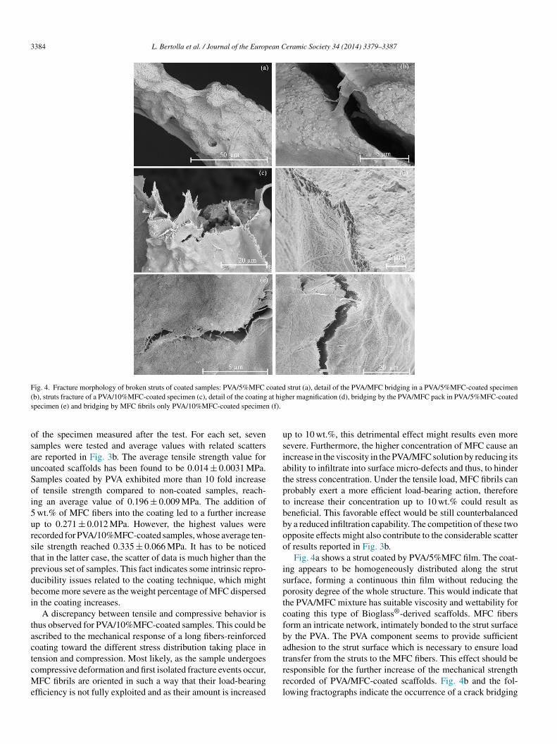
Fig. 4. Fracture morphology of broken struts of coated samples: PVA/5%MFC coated strut (a), detail of the PVA/MFC bridging in a PVA/5%MFC-coated specimen( at higs (f).
osauSoi5urstpdbi
tactcMe
usiatptbboo
isptcfbat
b), struts fracture of a PVA/10%MFC-coated specimen (c), detail of the coatingpecimen (e) and bridging by MFC fibrils only PVA/10%MFC-coated specimen
f the specimen measured after the test. For each set, sevenamples were tested and average values with related scattersre reported in Fig. 3b. The average tensile strength value forncoated scaffolds has been found to be 0.014 ± 0.0031 MPa.amples coated by PVA exhibited more than 10 fold increasef tensile strength compared to non-coated samples, reach-ng an average value of 0.196 ± 0.009 MPa. The addition of
wt.% of MFC fibers into the coating led to a further increasep to 0.271 ± 0.012 MPa. However, the highest values wereecorded for PVA/10%MFC-coated samples, whose average ten-ile strength reached 0.335 ± 0.066 MPa. It has to be noticedhat in the latter case, the scatter of data is much higher than therevious set of samples. This fact indicates some intrinsic repro-ucibility issues related to the coating technique, which mightecome more severe as the weight percentage of MFC dispersedn the coating increases.
A discrepancy between tensile and compressive behavior ishus observed for PVA/10%MFC-coated samples. This could bescribed to the mechanical response of a long fibers-reinforcedoating toward the different stress distribution taking place inension and compression. Most likely, as the sample undergoes
ompressive deformation and first isolated fracture events occur,FC fibrils are oriented in such a way that their load-bearingfficiency is not fully exploited and as their amount is increased
rrl
her magnification (d), bridging by the PVA/MFC pack in PVA/5%MFC-coated
p to 10 wt.%, this detrimental effect might results even moreevere. Furthermore, the higher concentration of MFC cause anncrease in the viscosity in the PVA/MFC solution by reducing itsbility to infiltrate into surface micro-defects and thus, to hinderhe stress concentration. Under the tensile load, MFC fibrils canrobably exert a more efficient load-bearing action, thereforeo increase their concentration up to 10 wt.% could result aseneficial. This favorable effect would be still counterbalancedy a reduced infiltration capability. The competition of these twopposite effects might also contribute to the considerable scatterf results reported in Fig. 3b.
Fig. 4a shows a strut coated by PVA/5%MFC film. The coat-ng appears to be homogeneously distributed along the struturface, forming a continuous thin film without reducing theorosity degree of the whole structure. This would indicate thathe PVA/MFC mixture has suitable viscosity and wettability foroating this type of Bioglass®-derived scaffolds. MFC fibersorm an intricate network, intimately bonded to the strut surfacey the PVA. The PVA component seems to provide sufficientdhesion to the strut surface which is necessary to ensure loadransfer from the struts to the MFC fibers. This effect should be
esponsible for the further increase of the mechanical strengthecorded of PVA/MFC-coated scaffolds. Fig. 4b and the fol-owing fractographs indicate the occurrence of a crack bridging
L. Bertolla et al. / Journal of the European Ceramic Society 34 (2014) 3379–3387 3385
F ) of PVf
mtta(bdhosc
istporFdsofcafMo
3t
p
cacmifCmaMatfinfa6vipcdmtmrpimtt
ig. 5. Average Young’s modulus, tensile strength (a) and strain to elongation (bor 48 h) films, with related scatters are summarized.
echanism in a PVA/5%MFC-coated scaffold. In Fig. 4c a frac-ured strut of a tensile specimen is shown. In the proximity ofhe fracture surface, the coating appears as it has been strainednd broken MFC fibers can be observed at higher magnificationFig. 4d). These images indicate that fibers are effective as load-earing elements. It is worth to point out that both Fig. 4c and
refer to specimens which have been deformed beyond theirighest stress peak, in order to observe toughening mechanismsccurring in the plateau region. The evaluation of coating adhe-ion strength will be required to ascertain if the debonding of theoating might contribute to the overall toughening of a scaffold.
The occurrence of the crack bridging mechanism is evidentn Fig. 4e and f, involving both the MFC and PVA. The fibrilspatial distribution along the crack front appears as optimal forhe reinforcement purpose either considering the energy dissi-ation, arising from the fracture of single fibrils and the crackpening limitation effect. There is a larger pack of MFC fib-ils in the PVA matrix bridging the crack in the strut shown inig. 4e which can be taken as an evidence of non-homogeneouslyistributed MFC fibrils in the coating. Despite that, fibrils cantill supply effective reinforcing effect mainly in the final stagef specimen elongation. An analogous behavior was reportedor PVA/20%MFC-coated scaffolds in Ref. 27. Fig. 4f shows arack bridging carried out by MFC fibrils only, without extensivessistance of the PVA matrix. SEM observations of fracture sur-aces of tensile samples therefore confirm the beneficial effect of
FC addition for the improvement of the mechanical propertiesf porous brittle scaffolds.
.4. Mechanical performance of coating materials under
ensile loadingThe results obtained from tensile tests on PVA/MFC stripesrovide a better understanding of the mechanical behavior of
ts
A, PVA/5%MFC, PVA/10%MFC (stirred for 24 h) and PVA/10%MFC (stirred
oated scaffolds. For each kind, five samples were tested andverage values of tensile strength and elastic modulus were cal-ulated. Tensile strength values were determined dividing theaximum load recorded by the cross-sectional area of the spec-
men measured before the test and the elastic modulus wasound by interpolating the linear part of the stress–strain curves.ross-head speed was set as 1 mm/min. The tensile strength andodulus of pure PVA stripes are respectively 66.26 ± 5.91 MPa
nd 4.15 ± 0.33 GPa. The addition of 5 wt.% and 10 wt.% ofFC fibers cause depletion of elastic modulus and strength
s the precursor mixtures are stirred for 24 h. By increasinghe mixing time of PVA/MFC mixture up to 48 h, the MFCbers seems to become effective as a reinforcing element andoticeable enhancement of strength and modulus is achieved. Inact for PVA/10%MFC specimens stirred for 48 h, the strengthnd elastic modulus reach respectively 109.27 ± 8.11 MPa and.42 ± 0.27 GPa. Results are summarized in Fig. 5a. As pre-iously reported,21 the achievement of a homogeneous andntimate dispersion of MFC fibers in polymeric matrix is a keyarameter for the mechanical strengthening of MFC-reinforcedomposites. A comprehensive study about the influence ofifferent processing parameters on the PVA/MFC compositeicrostructure has been provided by Bulota et al.32 Contrary
o the author’s results, they recorded a depletion of the overallechanical properties of the PVA/MFC composites as the stir-
ing time increase, yet a satisfactory explanation has not beenrovided. In fact the viscosity and pH measurements reportedn Ref. 32, excluded the occurrence of PVA degradation duringixing. Furthermore, polarized light microscopy also excluded
he presence of contaminating nuclei, hence their thesis is ques-ionable.
For all the composite stripes, the strain to fracture turned outo be remarkably lower than the neat PVA stripes and progres-ively decrease as concentration of MFC increase (Fig. 5b). This

3386 L. Bertolla et al. / Journal of the European Ceramic Society 34 (2014) 3379–3387
FC f
tdtb
mtbcceettr
fifinbudimb
ctfillopf
mAbfrtrtwfiFpsmm
4
tept
fmss5sb
Fig. 6. MFC fibrils observation (a), fracture surfaces of a PVA/10M
rend is consistent with the extension of plateau regions recordeduring tensile tests of coated scaffolds and it is in agreement withhe percolation theory of MFC-reinforced composites reportedy Zimmermann et al.21
On the contrary, there is no consistence between strength andodulus values measured for coated Bioglass® scaffolds and
he coating films. In the first case reinforcing effect seemed toe tightly connected to the amount of fibers dispersed in theoating, whereas in the case of coating films, the stirring timeame out as the crucial parameter for the achievement of anffective reinforcement. There are various aspects which mayxplain this behavior. First, the loading modality occurring inhe two cases surely differs. Beside this, the differences relatedo the substrate on which the coating deposed may also play aole, i.e. shape, surface chemistry, roughness etc.
SEM observations carried out on the surface of pure MFClms provided insights about sizes and aspect ratio of the MFCbrils used in this work (Fig. 6a). In spite of hornification phe-omenon (i.e. the formation of a large number of hydrogen bondsetween the hydroxyl groups of adjacent nanofibrils occurringpon drying of aqueous MFC suspensions,33) it is possible toistinguish the single fibrils and estimate their diameter approx-mately as 50 nm. A precise determination of their length is a
ore difficult task because of the deeply entangled configurationut it can be roughly estimated in the range of 2–10 �m.
Fracture surfaces of the broken films are shown. Fig. 6b and reflect the mechanisms of deformation and fracture respec-ively for PVA/10%MFC stirred for 24 h and for PVA/10%MFCoil stirred for 48 h. In Fig. 6b it is possible to observe somenhomogeneity in the structure caused by sedimentation of MFConger fibrils at the side of the Teflon® plate. This phenomenonikely indicates a poor dispersion of MFC and the precipitation
f bundles of fibers, similarly to the precipitation of flocculatedarticles occurring in a colloidal suspension. The fracture sur-ace of the PVA/10%MFC film stirred for 48 h (Fig. 6b) appearssc
t
oil stirred for 24 h (b) and a PVA/10MFC film stirred for 48 h (c).
uch rougher and exhibits two level of the MFC influence. microlevel represented by very fine fracture features causedy separate MFC fibrils and a macrolevel associated with theracture of packs formed by the MFC fibrils bundle and sur-ounding PVA matrix. Both this fracture mechanisms contributeo the overall increase of the fracture energy. Hence, the optimaleinforcing effect of the composite coating is expected whenhe coating exhibits the highest rigidity and toughness. It is alsoorth noticing that the fracture surface shown in Fig. 6c exhibitsbrous character, similarly to the coating fracture reported inig. 4d. In both cases, the amount of fibers is the same but therocessing conditions differ (24 h vs. 48 h stirring). This is a clueuggesting that the substrate on which the coating is deposed (i.e.aterial and morphology) can effectively influence the final filmorphology.
. Conclusions
An ethanol-based slurry has been adopted for the first time forhe production of 45S5 Bioglass® scaffolds. Resulting scaffoldsxhibited 3D interconnected structure with high degree of openorosity (45 PPI). PVA/MFC composite coatings were appliedo the scaffold in order to improve their mechanical response.
The effectiveness of a PVA/MFC composite coating as rein-orcement for bioactive glass based scaffolds has been proven byechanical and microstructural characterization. PVA-coated
amples exhibited approximately 5 fold increase of compres-ive strength compared to uncoated ones and the addition of
wt.% of MFC fibers led to a 10 fold increase of compressivetrength. Also tensile strength has been found to be improvedy the PVA/MFC composite coating; the PVA/10%MFC-coated
amples exhibited more than 20 fold increase of tensile strengthompared to non-coated samples.SEM observations showed how PVA is able to infiltrate withinhe struts surface defects by hindering the stress concentration
ean C
aIdt
ttfipsbm
A
tNtIefi1
R
1
1
1
1
1
1
1
1
1
1
2
2
2
2
2
2
2
2
2
2
3
3
3
L. Bertolla et al. / Journal of the Europ
nd providing stress transfer from the scaffold to the MFC fibers.n addition, fracture of MFC fibers contributed to the energyissipation process which led to the increase of the toughness ofhe scaffolds.
As future development, the rheology of the polymeric solu-ion (i.e. optimal MFC/PVA ratio) must be investigated in ordero achieve a more homogeneous distribution of the compositelm on the struts surface and possibly to enable an effectiveenetration and filling of the central hole in the struts. Adhesiontrength measurements are required to assess the quality of theonding between the coating and the strut surfaces which has aarked effect on the extent of toughening by the coating.
cknowledgements
Financial support from GlaCERCo – ITN EU project, Con-ract No. 264526 within Marie-Curie Action “Initial Trainingetworks” is acknowledged. Support to this research through
he infrastructure project ED1.1.00/02.0068 – Central Europeannstitute of Technology, CEITEC – is also gratefully acknowl-dged. A part of the research has been carried out thanks tonancial support of Czech Science Foundation, project Nr. 14-12345.
eferences
1. Hench LL. The story of Bioglass®. J Mater Sci – Mater Med 2006;17:967–78.
2. Hench LL. Bioactive materials for gene control. In: Hench LL, JonesJR, Fenn MB, editors. New materials and technologies for healthcare.Singapore: World Scientific; 2011. p. 25–48.
3. Chen QZ, Thompson ID, Boccaccini AR. 45S5 Bioglass®-derivedglass-ceramic scaffolds for bone tissue engineering. Biomaterials2006;27:2414–25.
4. Yang G, Yang X, Zhang L, Lin M, Sun X, Chen X, et al. Counterionicbiopolymers-reinforced bioactive glass scaffolds with improved mechanicalproperties in wet state. Mater Lett 2012;75:80–3.
5. Yunos DM, Bretcanu O, Boccaccini AR. Polymer-bioceramic compositesfor tissue engineering scaffolds. J Mater Sci 2008;43(13):4433–42.
6. Peroglio M, Gremillard L, Chevalier J, Chazeau L, Gauthier, Hamaide T.Toughening of bio-ceramic scaffolds by polymer coating. J Eur Ceram Soc2007;27(7):2679–85.
7. Xu C, Su P, Chen X, Meng Y, Yu W, Xiang AP, et al. Biocompatibility andosteogenesis of biomimetic Bioglass-Collagen-Phosphatidylserine compos-ite scaffolds for bone tissue engineering. Biomaterials 2011;32(4):1051–8.
8. Mourino V, Newby P, Boccaccini AR. Preparation and characterization ofgallium releasing 3-D alginate coated 45S5 Bioglass® based scaffolds forbone tissue engineering. Adv Eng Mater 2010;12(7):B283–91.
9. Wu C, Xiao Y. Mesoporous bioglass/silk composite scaffolds for bone tissueengineering. In: Rosario P, editor. Biomaterial (Book 2). INTECH OpenAccess Publisher; 2011. p. 269–86.
0. Metze AL, Grimm A, Nooeaid P, Roether JA, Hum J, Newby PJ, et al. Gelatincoated 45S5 Bioglass®-derived scaffolds for bone tissue engineering. KeyEng Mater 2013;531:31–9.
1. Yao Q, Nooeaid P, Roether JA, Dong Y, Zhang Q, Boccaccini AR.Bioglass®-based scaffolds incorporating polycaprolactone and chitosancoatings for controlled vancomycin delivery. Ceram Int 2013;39(7):7517–22.
3
eramic Society 34 (2014) 3379–3387 3387
2. Yunos DM, Ahmad Z, Salih V, Boccaccini AR. Stratified scaffolds for osteo-chondral tissue engineering applications: electrospun PDLLA nanofibrecoated Bioglass®-derived foams. J Biomater Appl 2013;27(5):537–51.
3. Bretcanu O, Misra S, Roy I, Renghini C, Fiori F, Boccaccini AR, et al.In vitro biocompatibility of 45S5 Bioglass®-derived glass-ceramic scaffoldscoated with poly(3-hydroxybutyrate). J Tissue Eng Regen Med 2009;3(2):139–48.
4. Li W, Nooeaid P, Roether JA, Schubert DW, Boccaccini AR. Preparation andcharacterization of vancomycin releasing PHBV coated 45S5 Bioglass®-based glass-ceramic scaffolds for bone tissue engineering. J Eur Ceram Soc2014;34:505–14.
5. Roohani-Esfahani SI, Nouri-Khorasani S, Lu Z, Appleyard R, Zreiqat H.The influence hydroxyapatite nanoparticle shape and size on the propertiesof biphasic calcium phosphate scaffolds coated with hydroxyapatite-PCLcomposites. Biomaterials 2010;31(21):5498–509.
6. Paradossi G, Cavalieri F, Chiessi E, Spagnoli C, Cowman MK. Poly(vinylalcohol) as versatile biomaterial for potential biomedical applications. JMater Sci Mater Med 2003;14(8):687–91.
7. Kim CJ, Lee PI. Composite poly(vinyl alcohol) beads for controlled drugdelivery. Pharm Res 1992;9(1):10–6.
8. Robert J, Moon RJ, Martini A, Nairn J, Simonsen J, Youngblood J. Cellulosenanomaterials review: structure, properties and nanocomposites. Chem SocRev 2011;40:3941–94.
9. Siró I, Plackett D. Microfibrillated cellulose and new composite materials:a review. Cellulose 2010;17:459–94.
0. Herrick FW, Casebier RL, Hamilton JK, Sandberg KR. Microfibril-lated cellulose: morphology and accessibility. Appl Polym Symp 1983;37:797–813.
1. Zimmermann T, Pöhler E, Geiger T. Cellulose fibrils for polymer reinforce-ment. Adv Eng Mater 2004;2:754–61.
2. Bruce DM, Hobson RN, Farrent JW, Hepworth DG. High performancecomposites from low-cost plant primary cell walls. Appl Sci Manufact2005;36:1486–93.
3. Lu J, Wang T. Preparation and properties of microfibrillated cellulosepolyvinyl alcohol composite materials. Compos Part A Appl Sci Manufact2008;39(5):738–46.
4. Qiu K, Netravali AN. Fabrication and characterization of biodegradablecomposites based on microfibrillated cellulose and polyvinyl alcohol. Com-pos Sci Technol 2012;72(13):1588–94.
5. Li W, Garmendia N, Perez de Larraya U, Ding Y, Detsch R, Grünewald A,et al. 45S5 Bioglass®-based scaffolds coated with cellulose nanowhiskersfor bone tissue engineering. Appl Surf Sci 2014 [submitted for publication].
6. Rehorek L, Chlup Z, Meng D, Yunos DM, Boccaccini AR, DlouhyI. Response of 45S5 Bioglass® foams to tensile loading. Ceram Int2013;39(7):8015–20.
7. Bertolla L, Dlouhy I, Philippart A, Boccaccini AR. Mechani-cal reinforcement of Bioglass®-based scaffolds by novel polyvinyl-alcohol/microfibrillated cellulose composite coating. Mater Lett 2014;118:204–7.
8. Svagan AJ, My AS, Samir A, Berglund LA. Biomimetic polysaccharidenanocomposites of high cellulose content and high toughness. Biomacro-molecules 2007;8:2556–63.
9. Rehorek L, Dlouhy I, Chlup Z. Tensile behaviour of open cell ceramic foams.Ceramics-Silikáty 2009;53(4):237–41.
0. D’Angelo C, Ortona A, Colombo P. Finite element analysis of reticulatedceramics under compression. Acta Mater 2012;60(19):6692–702.
1. Brezny R, Green DJ, Dam CQ. Evaluation of strut strength in open-cellceramics. J Am Ceram Soc 1989;72:885–9.
2. Bulota M, Jääskeläinen AS, Paltakari J. Properties of biocomposites: influ-
ence of preparation method, testing environment and a comparison withtheoretical models. J Mater Sci 2011;46:3387–98.3. Fernandes Diniz JM, Gil MH, Castro JA. Hornification: its origin and inter-pretation in wood pulp. Wood Sci Technol 2004;37:489–94.