Marine turtle Marine iguana Saltwater crocodile Marine Reptiles Sea snake.

452 East Hill Road Fax: 707.459.6617Willits, CA 95490 USA E-mail: [email protected]: 707.459.5563 www.microphor.com 24533.WPDToll Free: 1.800.358.8280 www.wabtec.com 10/19/01
Model LF-210 Model LF-219
Model LF-310 Model LF-320
Microflush Half Gallon Toilets
Marine HeadsAir Operated
Installation/Service Manual P/N 24533

Marine Head Manual P/N 24533 2 June 25, 2002
THANK YOU FOR PURCHASING AMICROPHOR® PRODUCT!Your Microflush® Marine Head is designed toprovide you with years of reliable service whileusing only two quarts of salt or fresh water perflush. Please read this Owner's Manual completelyprior to installation of your Microflush MarineHead. This will familiarize you with all of theproper installation and operation requirements.
CUSTOMER SERVICE - Please contact yourlocal Microphor dealer for parts and service. For alist of dealers, please contact Microphor at theaddresses listed on the cover of this manual.
AIR SYSTEMFilter-regulators areavailable in a variety ofsizes and types. Theirpurpose is to removewater, oil and otherforeign matter from the airline and to maintain aconstant pressure at thetoilet of 60-65 PSI. The following steps must beobserved to assure moisture will be removed fromthe airline:1. Drain air compressor receiver regularly. Most
water tends to accumulate at this point.2. Install drip legs with condensate drains at all low
points in air piping.3. Whenever possible, grade all airlines back to the
air receiver or drip leg assembly and drainregularly.
4. The air supply to your Microflush Marine Headmust be taken from the top of the main or branchair line.
AIR COMPRESSOR
Be certain compressor crankcase has proper oillevels. Locate the compressor in a clean, dry, wellventilated location. Size compressor according toseparate Air Compressor Specifications Sheet.
ITEM LF-210 LF-219LF-310LF-320
Air Line Connection Compression 1/4" 45o
Flare Fitting
Water LineConnection
1/2"MIPSSlip JointNut
3/4" IDHoseBarb
1/2" FNPTFitting
DrainConnection
Down
12"(305mm)on center-line
2.25"(57mm);3.6" (91mm)offcenter-line
NotAvailable
Rear1-1/2" outlet, 3/4"(19 mm) offcenterline
Centerline
Remote ValveAssembly
Must be mounted so vacuumbreaker is located 6" above rim oftoilet bowl.
1 PRE-INSTALLATION Following procedures apply
to all Microflush modelsunless otherwise noted.
Remove your Marine Headfrom box carefully.Integral Models - Install toilet seat and flushhandle before mounting Microflush to floor. Seat is not included with LF-210 and LF-219models. Bolt caps and closet screws areprovided with LF-210 and LF-219 models.

Marine Head Manual P/N 24533 3 June 25, 2002
2 AIR LINES All piping
supplied bycustomer is toconform toU.S.C.G.requirementsrelating towater tightdecks andbulkhead (46CFR56.69)
Be sure airline from compressor is of sufficientsize, based on length of pipe run to head. Wesuggest 3/8" air line up to 40', 1/2" air line up to75', and 3/4" air line for over 75'.
Install a filter-regulator assembly in incomingairline. Place the filter-regulator as close aspossible to the first Microflush Marine Head andin an accessible location.
Set filter-regulator so that 60-65 psi constant isavailable at the head. Install an in-line air dryer,Microphor P/N 30054 or combinationfilter/regulator/dryer, P/N 94036.
Assemble the Air Connecting Kit provided andconnect to incoming air line with shut-off valvebetween bulkhead and toilet. For LF-210Models, use Air Connecting Kit P/N 93086, andfor LF-219 Integral Models use Air ConnectingKit P/N 95172. The plastic airline provided goesfrom the air supply to the Flush Activator. Onintegral models, the plastic air line enters theMicroflush through the back wall or up throughthe floor under the unit. Make sure air is OFF atair compressor.DO NOT CONNECT TO FLUSHACTIVATOR YET!
3 WATER LINESUse a 1/2" water line and install a water shut-offvalve (angle stop) between bulkhead and toilet. Water at the head must be regulated at an evenpressure between 20 to 50 PSI for Microflush tooperate properly. Optimum pressure is 35 PSI. DO NOT CONNECT WATER LINE TOMICROFLUSH YET.
INSTALLATION PROCEDURES
4 DRAIN CONNECTION - See Rough-inDimensions
For direct overboard discharge, contactMicrophor or your dealer.
When using a 1-1/2" (38.1 mm) discharge line,each toilet must go individually to the MSD orholding tank. Do not connect more than onetoilet to a 1-1/2" (38.1 mm) discharge line.
If a vertical rise is required, the vertical rise mustbe at the toilet. The maximum vertical rise is36". The maximum horizontal run is 30 feet(9.14 meters) and must slope a minimum of 1/8"per foot (1 in 100) towards the MSD or holdingtank. For 1-1/2" lines, reduce horizontal pipe run2 feet (.68 meters) per 90o elbow. Use longsweep elbows, do not use 45o elbows. Do notuse the inverted P-Trap with a vertical rise.
When multiple heads are installed, a vented 3"gravity collection line is to be used with not morethan 4 heads per 3" line. Manifold the 1-1/2"lines into the 3"collection line and provide agrade of at least 1/4" per foot towards the MSDor holding tank. Vent 3" line at the manifoldpoint.
Holding tank or MSD must be vertically ventedto atmosphere via 3" vent, terminating at highestpoint possible. Limit the number of 45o or 90o
fittings. Do not install loops on end of vent.
For holding tank installations, consider installinga power fan sized so that a volume of air equal tothe empty tank volume is exchanged every 30 to60 seconds. The negative pressure shall notexceed -1.3 psi. This will allow for good airflow out the vent.
Your Microflush Marine Head discharge linemust have a rise (trap) in order to provide backpressure during the flush cycle - see Rough-inDimensions on pages 14-15.Caution: Do not apply stress to alignMicroflush rear or downward dischargeoutlet to waste line. This will result in eventualdamage to seal between Hopper and Toilet Bowl,causing leaking. Do not use the P-Trap with avertical rising waste line.
LF-210 Downward Discharge Model: Rest Microflush on it's back on a padded surface (e.g.

Marine Head Manual P/N 24533 4 June 25, 2002
shipping box). Center wax ring over HopperFlange. Turn Microflush Marine Head over, liftup, and center it with the horn of the wax ring intostandard floor flange located on centerline 12"from wall. Compress the wax ring by applyingweight to your Microflush Marine Head. A secondstandard wax ring may be added if floor is uneven. If Hopper Flange hits floor flange, grind it downfor added clearance, as any contact will break sealbetween Hopper and Toilet Bowl, causing leaking.
All Rear Discharge Models: Install invertedP-Trap supplied with Microflush Marine Head. Donot glue or connect fittings until fitting alignmenthas been checked. Caution: Outlet of LF-210 and LF-219 Models is3/4" off centerline. Make sure head discharge andwaste line are in line, not off set.
When using a 1-1/2" discharge line, a vertical liftof 36 inches can be achieved in single headapplications. The vertical rise must be at the toilet. This vertical application is not advised forcommercial, high use applications. Do not use theP-Trap with a vertical rising waste line. Pleasecontact the factory for further information.
LF-219 Model: For downward discharge, usemolded P-Trap hose supplied. For rear dischargeuse inverted P-Trap. See page 9 for part numbers.
Remote Models: Position and mount the RemoteValve Assembly making sure the Vacuum Breakeris at least 6" above the rim of the MicroflushMarine Head bowl. Measure air and water lines tomake sure Remote Valve is mounted withinconnection distance to Microflush Marine Head. Run water and the three air lines from the RemoteValve Assembly to Microflush. Caution: For Remote Flush Activators, make sureinside wall thickness does not exceed 1/2" or largemounting nut will restrict movement of flushhandle.
Mount toilet bowl to floor. LF-210 and LF-219models mount to floor with 1/4" closet boltsprovided. Screw on bolt caps to mounting screws.Model LF-310 and LF-320 models are bolted tofloor, bolts not provided.
LF-320 Models: 1 Remove side panels to facilitate mounting toilet.2 Connect 7' water line to Spud fitting at the back of
the toilet bowl.3 Run water and the three air lines from the
Microflush through wall access (maximum 7feet).
4 Position toilet and connect hopper dischargeoutlet to waste line.
5 Bolt toilet to floor and attach back plate to wall. Do not reposition toilet after it is connected tothe waste line as this may break the seal betweenbowl and Hopper and cause a water leak. Re-install side panels on toilet.
6 Connect the three air supply lines to theAir/Water Sequence Valve, color coded lines tomatching color coded fittings.
7 Mount Remote Valve Assembly at least 6" abovethe rim of the bowl, and mount the FlushActivator assemblies at desired location on wall.
5 WATER CONNECTIONNever install a check valve on the inlet side ofthe Microflush head.
Integral Models - Connect incoming water fromangle stop to water connector. Make sureWATER IS OFF at angle stop.LF-210 Models -water supply connector is madeof nylon-plastic. Be careful not to cross threads.
LF-219 Models - if integral model is connectedto a potable water source, the unit requiresinstaller to provide a Back Flow/CrossContamination Prevention device. Please checkapplicable jurisdiction for requirements beforeinstallation.
LF-310 Models - use back-up wrench on waterinlet. DO NOT allow inlet fitting to turn and beforced into Air/Water Sequence Valve.
Remote Models - Connect incoming water fromangle stop to Microflush Hose Barb on theRemote Valve Assembly. Connect the waterline from Remote Valve Assembly to the FlushRim Spud Assembly. Make sure WATER ISOFF at angle stop.

Marine Head Manual P/N 24533 5 June 25, 2002
START UP1 Turn air ON air supply at
compressor. 2 Turn air ON at air
shut-off cock (near butnot connected to FlushActivator) to blow outairlines for a few seconds. This procedure shouldremove any debris or contaminants from theairline. Turn air OFF at shut-off valve.
3 Connect airline to Flush Activator. Make sure airshut-off valve is installed next to Flush Activator. Do not over-tighten fittings.
4 Turn ON air shut-off cock. Check total installationfor air leaks using soapy water.
5 Turn ON water. Check for water leaks.6 Flush you Microflush Marine Head four times,
waiting twenty seconds between flushes to getwater through system and operating regularly. Toflush properly, hold down Flush Activator Handleor Button until flapper opens.
DOUBLE CHECK1 Air pressure at Microflush Head is at 60-65 psi.2 Water Pressure at Microflush Head is between
20-50 psi, 35 psi optimal.3 Water level in bowl should be at top edge of
flapper opening.If your Microflush does not operate correctly, referto troubleshooting sections.
FLUSH CYCLE ACTIVATORSThere are two types of Flush Activators:
Standard - hold handle or button down for 1second.
Positive - barely push handle or button toactivate.
CLEANING BLEED-OFF PLUGASSEMBLYStandard Flush:Remove plug and clean with solvent; air blow dry.
Positive Flush:Remove plug and clean with solvent; air blow dry;remove and clean plug on Detent Valve.
Note: Use 5/32"or 4mm Allen wrench to removeplugs.
Note: Bleed-Off Plugs on Air & Water Sequence Valvesand Detent Valves are different sizes that are notinterchangeable.
MAINTENANCE/CLEANING/CLEARING/WINTERIZING
ROUTINE MAINTENANCE

Marine Head Manual P/N 24533 6 June 25, 2002
USAGE LUBRICATELight Every 5 yearsMedium Every 2-3 yearsHeavy Every year
WARNINGSDo not use any petroleum based lubricants
(Vaseline) on any rubber parts or o-ringsas damage will occur. Use only siliconebased lubricants.
Do not use any ‘Locktite’ brand adhesives on anyplastic or Delrin components as fumes willcause damage.
Do not use Teflon tape on any air fittings asclogging may occur.
Your Microflush MarineHead has an air-operatedAir/Water SequenceValve which requiresperiodic lubrication witha silicone basedlubricant. Check yourapplication at right todetermine how often tolubricate your Air/Water Sequence Valve. The AirCylinder should be serviced if you have to take upyour Microflush Marine Head for any reason. The airsystem must be free of moisture. Drain airreceiver regularly to remove moisture.
CLEANING Use Micro-Clean Organic Spray Cleaner, P/N 24542.Sanitizers like Lysol, Pine-Sol, Hexol, ammoniabase products, caustic drain openers ornon-biodegradable cleaners should never be used ifthe plumbing system is connected to a MicrophorMSD.1 While depressing the Flush Activator, turn OFF the
water. Allow the bowl cleaner to flow into thelower chamber. Keep the Flushing Activatordepressed.
2 Insert bowl brush into lower chamber and agitatemixture carefully. Remove the bowl brush andrelease the flush activator.
3 Turn the water ON and flush twice to rinsethoroughly.
NOTE: LF-310 or LF-320 Stainless Heads may besubject to surface rusting, especially if salt water isused for flushing and if bleach or a corrosive productor cleaner is left standing in or on the bowl. The saltwater will enhance the oxidation qualities of thebleach (or product containing bleach). If it sits on thestainless and the surface remains damp, the chromeand nickel will etch out of the stainless, leaving ferriteiron, which will rust. If bleach or any cleaner is used,it must be well rinsed, not left standing (soaking) inthe bowl or on the toilet, especially in toilets using saltwater.
CLEARING YOUR MICROFLUSH HEADIf your Microflush Marine Head becomes plugged,shut off the water supply, press the flush handle andhold. The flapper will remain open until flushhandle is released. Check to see if the restrictioncan be removed from lower portion of MicroflushMarine Head with a hooked wire, being careful notto damage the rubber seal on the flapper or themating surface on the hopper. If obstruction cannotbe picked out with a hook or tongs, use plunger bypushing in slowly and pulling out quickly to pullobject back into the hopper. If necessary, turn airoff and use a snake inserted through a short plasticpipe placed in hopper. Pipe will protect flapperseal. If valve will not operate with water off, holdflush lever down and turn water on and off quicklyto free valve action. When the passage becomesclear, turn on water and press flush handle to startflush cycle.
WINTERIZING (out-of-service winter storage)Shut OFF water to Microflush Marine Head. FlushMicroflush Marine Head three times or until waterno longer flows into the bowl. Unhook water supplyat angle stop. Empty water in line into receptacle. Shut OFF air supply to your Microflush MarineHead. The unit is now prepared for freezingtemperatures. OPEN petcocks on drip legs and airreceiver drain after shutting down air compressorand isolating airlines. Use of Anti-freeze is notrecommended.
PATENTSMicroflush® Toilets are covered by one or more ofthe following U.S. patents: 5245710; 4918764;1280554; 169471 and related foreign patents.
DESIGN CHANGESContinuing a policy of research and development,Microphor reserves the right of price, product or designchange without notice or obligation.

Marine Head Manual P/N 24533 7 June 25, 2002
TROUBLESHOOTING Your Microflush® toilet is designed to give you years of trouble-free operation. Please check the followingbefore beginning any service or repair:
Water supply: 1 Is the water turned on?2 Is the water pressure between 20 and 50 psi at the toilet for pressure water system?3 Is there 6 feet minimum of head for gravity systems?Fluctuating or high water pressure can cause intermittent problems with the toilet operation. Check the water pressure at different times of the day (i.e., early morning, noon, evening) todetermine if you have fluctuating or high water pressure. A pressure-reducing valve installed onthe incoming water line will assure you have even pressure. Make sure no check valve isinstalled before the Air/Water Sequence Valve.
Air system: 1 Is the air turned on?2 Is the air pressure set at a constant 60-65 psi at the toilet?3 Do you have any air leaks or kinks in the air system?4 Do you have water in the air system? This usually causes irregular timing.Drain the compressor tank and check the filter regulator and drip leg(s) for water. To check forwater in Air/Water Seq. Valve, remove Bleed-Off Plug, put finger over screw opening and flush. If water is present, it will squirt out. If water is detected, then the air cylinder and airlines mustalso be drained.
Cycle time: 1 Is the flapper cycle time set correctly at 4-8 seconds?2 Is the bleed off assembly plug blocked? Remove, clean and reinstall (see page 5).
Trouble Possible Causes CorrectionFlapper does not open.Water does not flow.Nothing happens.
1 No Air Supply to Microflush.2 Water has accumulated in
Air/Water Sequence Valve
1 Supply compressed air at 60-65psi at the toilet
2 See 'Check Air System" above.Flapper opens and closes 4-8seconds after handle is released,but no water enters bowl.
1 No water supply to Microflush.2 Water turned off.
1 Supply water at 20-50 psi.2 Open angle stop (shut-off
valve).Flapper opens when flushed, andcloses immediately when activatoris released.
1 Excessively high waterpressure.
2 Debris in check valve at base ofAir/Water Sequence Valve.
1 Install water pressureregulating valve, set at 20-50psi.
2 Clean Air/Water Seq. Valve.Flapper opens and will not close. Bleed Off plug blocked. Remove, clean or replace,
reinstall.Water continues to run whenMicroflush is not in use.
Foreign object is under watervalve in Air/Water SequenceValve.
Clean Air/Water Sequence Valve. Reference Service Kit P/N 95057.
Water splashes when flushed. Water is too high in bowl. Reduce incoming water via anglestop.
Flush cycle is too long. Bleed-Off Plug blocked. Remove, clean or replace,reinstall.
Flush cycle is too short. Air line leakage. Check for air leakage at allconnections.
If other problems are encountered, please contact the factory: Toll Free: 1-800-358-8280
Marine Head Manual P/N 24533 8 June 25, 2002
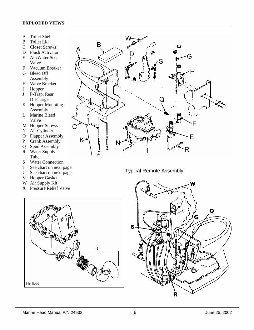
Typical Remote Assembly
EXPLODED VIEWS
A Toilet ShellB Toilet LidC Closet ScrewsD Flush ActivatorE Air/Water Seq.
ValveF Vacuum BreakerG Bleed Off
AssemblyH Valve BracketI HopperJ P-Trap, Rear
DischargeK Hopper Mounting
AssemblyL Marine Bleed
ValveM Hopper ScrewsN Air CylinderO Flapper AssemblyP Crank AssemblyQ Spud AssemblyR Water Supply
TubeS Water ConnectionT See chart on next pageU See chart on next pageV Hopper GasketW Air Supply KitX Pressure Relief Valve

Marine Head Manual P/N 24533 9 June 25, 2002

Marine Head Manual P/N 24533 10 June 25, 2002
PARTS CHART
MODELPART
LF-210 ChinaRound
LF-210 ChinaElongated
LF-219 China RoundIntegral & Remote
LF-310 SSRound
LF-320 SSRound
A Toilet Shell 44032 - whitecolors - see
chart
44010 - whitecolors - see
chart
44151 - integral, white44133 - remote, whitecolors - see chart
93082 - shell93084 - top shroud93085 - bottomshroudcolors - see chart
93008 - shellcolors - see
chart
B Toilet Lid 99064 - white99073 - bolt down, whitecolors - see chart
Not applicable
C Closet Screws& Bolt Caps
93972 - whitecolors - see chart
Not applicable
D Flush Activator 95002 - standard95054 - positive
40046-5/40049-5 int, wht40046-9/40049-9 int, blk40046-7/40049-7 int, bone95151 - remote
95561 - standard 95031 - standard
E Air/WaterSequence Valve
39501 - no fittings
F VacuumBreaker
33559 - integral33039 - remote
33421 - check valve33039 - remote
96539 - integral 33039 - remote
G Bleed-Off PlugAssembly
94598 30382-3 94598
H Valve Bracket 91897 - integral20003 - remote
91866 - integral20003 - remote
Not applicable 20003 - remote
I Hopper 90016-3 - rear 90008 - downward conversion kit
90016-3 - rear 95157 - downward hose
90039 - 3 rear40050-3 Tank isolation valve
40050-3 tank isolation valve27282 - Hopper Adaptor O-ring
J P-Trap, RearDischarge
96029
K HopperMounting Assy
90899-5 00006 (4 each) and 00106 (4 each)
L Hopper BleedValve
37548
M Hopper Screws 00064 (14 each) 00064 (10 each)
N Air Cylinder 94540
O Flapper Assy 90048
P Crank Assy 90042
Q Spud Assy 96347 95155 96579
R Water SupplyTube
96012 - integral35053 - remote
35484 - integral35484 - remote
96002 96008
S WaterConnection
96387 N/A - integral33352 - remote
96515 33352
T Air Fittings 30385 - 90E Elbow, 30365 - Straight
U Air Tubing/ft green - 35381, blue - 35382, red - 35383, yellow - 35384, white - 35385, black - 35419
V Hopper Gasket 27272 27270
W Air Supply Kit 93086 N/A
X Pressure ReliefValve
37518

Marine Head Manual P/N 24533 11 June 25, 2002
COLOR CHART - AIR LINE CONNECTIONS - SERVICE KITS
VITREOUS CHINA COLOR CHART
Color Code
LF-210 LF-219
RoundShell & Lid
ElongatedShell & Lid
LidOnly
RemoteShell
IntegralShell
White -- 44032 44010 99064 44133 44151Pastel Ivory SC1 44327 44328 99064-23 44133-3 44150Bone/Natural S4 44039 44012 99064-3 44134 44152 Harvest Beige SC4 44333 44334 99064-15 NA N/APink SR2 44331 44332 99064-21 NA N/AGrey 651 44329 44330 99064-5 44135 44153 Black N-5 44337 44338 99064-7 44130 44154
AIR LINE CONNECTIONSFrom Air/WaterSequence Valve ToRed, P/N 35383 Air Cylinder, bottom fitting White, P/N 35385 Air Cylinder, top fittingBlack, P/N 35419 Bleed Off PlugGreen, P/N 35381 Flush Activator, front fittingBlue, P/N 35382 Flush Activator, back fittingYellow, P/N 35384 Hopper
SERVICE KITS# P/N Description1 93100 Master Service Kit (2-5 below)2 95057 Air/Water Sequence Valve3 94502 Air Cylinder4 95020 Flush Activator Pilot Valve (standard) 5 95037 Vacuum Breaker6 95122 Positive Flush (Detent) Valve7 90066 Flapper Replacement Kit8 90070 Hopper Conversion Kit - Rear9 90071 Hopper Conversion Kit - Bottom

Marine Head Manual P/N 24533 12 June 25, 2002
HOPPER REPLACEMENT
Model LF-210 and LF-219 Models Only
CAUTION: Read this entire procedurebefore beginning work!
1. Remove toilet from floor. Place toiletupside down on a sheet of cardboard orother padded material.
2. Remove nuts from J-bolts on either sideof hopper, lift hopper from bowl.
3. Remove o-ring between hopper and sealadaptor. Check that o-ring is notdamaged, replace if necessary.
4. Re-assemble in reverse order. MAKE SURE J-BOLTS ARE TIGHT!Proper torque specification is 4-6inch/lbs.
Note: The air cylinder on the hopper sub-assembly should be cleaned, lubricated and checked for adjustmentwhenever the toilet assembly is removed for servicing.
TANK ISOLATION VALVE INSTALLATION (Not supplied with toilet.)
Note: Check valve halves for tightness beforeinstalling.
Rear Discharge with LF-219 Downward HoseInstall Tank Isolation Valve Assembly in lineat the end of the discharge hose using a 1-1/2"long pipe nipple.
Rear DischargeGlue tank isolation valve assembly to hopper atpoint indicated.
Bottom Discharge, No FlangeGlue Tank Isolation Valve Assembly directlyto hopper discharge as indicated.
Bottom Discharge with Flange (1-1/2" pipe)Glue 1/2" long pipe nipple to hopper dischargeport as indicated, and glue Tank IsolationValve assembly to pipe nipple.
NOTE: Isolation Valve is in two pieces;tighten valve before installation andagain before making drain connection!

Marine Head Manual P/N 24533 13 June 25, 2002
AIR CYLINDER ADJUSTMENT1 Remove Hopper (see Hopper Replacement).2 Remove the clevis pin retaining ring. Remove the clevis pin.3 Inspect the crank arm, clevis and clevis pin for wear. Replace if required.4 Hold the crank arm in the UP position (flapper closed).5 Fully extend the air cylinder and note the position of the holes in the crank arm and the clevis. The clevis
hole should extend half its diameter past the crank arm hole.6 Adjust as necessary by loosening the locknut and extend or retract the clevis as required.7 Re-install Hopper.
TO CHANGE FLAPPER GASKET: 1. Turn water and air off.2. Reach behind flapper to grasp gasket tails.3. Pull tails out of slots to remove old gasket.4. Installation is the reverse of removal.5. Tails must be pulled all the way through to insure smooth surface.
AIR/WATER SEQUENCE VALVECOMPONENTS
Components shown in italics are part of Kit, P/N 95057.
Spacers and Spool available as a set, P/N95530.
Water Body, Main Body and Bottom Capavailable as a set, P/N 39386.
Marine Head Manual P/N 24533 14 June 25, 2002
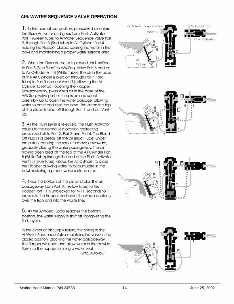
AIR/WATER SEQUENCE VALVE OPERATION

Marine Head Manual P/N 24533 15 June 25, 2002
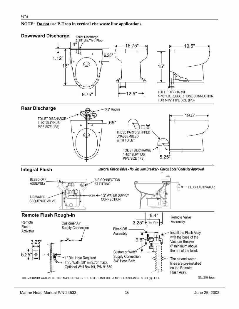
ROUGH-IN DIMENSIONS: LF-210, LF-310 and LF-320 Models. NOTE: All dimensions may vary ½"±
Reference Remote Flush Rough-In, next page.ROUGH-IN DIMENSIONS: LF-219 Models NOTE: All dimensions may vary
Marine Head Manual P/N 24533 16 June 25, 2002
½"±
NOTE: Do not use P-Trap in vertical rise waste line applications.

Marine Head Manual P/N 24533 17 June 25, 2002
Terms & Conditions here