Manufacturing Context & Technology Physics · ANSI Standard Limits and Fits (ANSI B4.1-1967,R1974)....
54
© Copyright 2019 HP Development Company, L.P. The information contained herein is subject to change without notice. Manufacturing Context & Technology Physics Ed Davis Strategy Director Office of the CTO Dustin Kloempken Applications Engineer © Copyright 2019 HP Development Company, L.P. The information contained herein is subject to change without notice.
Transcript of Manufacturing Context & Technology Physics · ANSI Standard Limits and Fits (ANSI B4.1-1967,R1974)....

© Copyright 2019 HP Development Company, L.P. The information contained herein is subject to change without notice.
Manufacturing Context & Technology PhysicsEd DavisStrategy DirectorOffice of the CTO
Dustin Kloempken Applications Engineer
© Copyright 2019 HP Development Company, L.P. The information contained herein is subject to change without notice.

© Copyright 2019 HP Development Company, L.P. The information contained herein is subject to change without notice.
OVERVIEW
1. Why it is paramount to know and understand manufacturing terminology? Why should you care?
2. How do part manufacturers talk about standards?• Dimensioning• Tolerancing• CpK• IT Scale
3. How do you differentiate between various manufacturing methods?• How do various additive technologies fit in?• How do various additive technologies compare to one another?• Where are the spots of confusion?
4. Where does HP Multi Jet Fusion (HP MJF) technology fit in?• Where is the technology today?• Where is it going?• How can existing manufacturing standards work with HP MJF technology?

© Copyright 2019 HP Development Company, L.P. The information contained herein is subject to change without notice.
POLL
1. What is your job function?
a) I run or support a internal/external service bureau
b) Product Marketing
c) Customer Service
d) Sales

© Copyright 2019 HP Development Company, L.P. The information contained herein is subject to change without notice.
POLL
2. Roughly how many parts a week is your organization printing?
a) None right now
b) 1-100
c) 100-250
d) 250-500
e) 500+

© Copyright 2019 HP Development Company, L.P. The information contained herein is subject to change without notice.
3D Prototypers transitioning to Production
Changing materials and re-calibrating machines frequently
Constantly troubleshooting machine, model, or file related issues
Possibly printing multiple times before you get a “good” model
Processing small batches of parts
Non-consistent maintenance schedules
Problems you might be faced with today:
Do you have time to always change materials and recalibrate when you are printing 100s of parts a day?
How are you able to maintain a production schedule if problems keep occurring?
A part processing line must be established to get repeatable, consistent, and high quality outputs.
If your part yield is low, it becomes very challenging to remain profitable.
Unplanned downtime is a production and costing timeline killer.
These problems prevent your business from scaling

© Copyright 2019 HP Development Company, L.P. The information contained herein is subject to change without notice.
3D Prototypers transitioning to ProductionTerminology repackaging
“How quickly can I get a prototype in my hands”
“What is the service number to troubleshoot this issue?”
“ Too much stepping or shrink? Print it again in a different orientation so that we can get a better looking part”
“ Oh we ran out of post processing supplies again, go get another one from the store”
“ Well, since our machine went down again we might as well do the PMs since they are due soon”
“What will it take to get 5000 parts in the next month under $5/part?”
“What is our backup plan to maintain production schedules if a failed build were to occur?
“What does our production ramp up schedule look like to verify that we are getting the yield of parts that we desire?”
“How many pounds of supplies and what tools will we need to adequately process 1000 parts a week for 6 weeks?”
“At what interval and how much time will we be down for preventative maintenance? Do we have all of the necessary tools and supplies ready?”
Current thought process Change in mindset
Throughput
Timelines
Quality
Preparation
Maintenance

© Copyright 2019 HP Development Company, L.P. The information contained herein is subject to change without notice.
3D Prototypers transitioning to Production
Whatever can get you a result fastest
Small number of parts within spec.
Measurement process to validate part dimensions
100% inspection rate
Process tuned to part design
Choosing the process that gets you part(s) the fastest
Selecting a process which meets your standard/ process capability
Many parts within spec.
Statistical process to validate dimensional success rates
SPC & Audit dimensions
Part design tuned to manufacturing process & process tuned to the part
Choosing the process that is the least expensive, meets your design requirements, and timetables.
MOVE FROM REACTIVE TO PROACTIVE
© Copyright 2019 HP Development Company, L.P. The information contained herein is subject to change without notice.
DEVELOPMENT ASSEMBLY & SUPPORT
Demand Side Supply Side
PRODUCT PARTS PROCESS PARTS PRODUCT
PART PRODUCTIONDESIGN
PRODUCT DEVELOPMENT LIFECYCLE
© Copyright 2019 HP Development Company, L.P. The information contained herein is subject to change without notice.
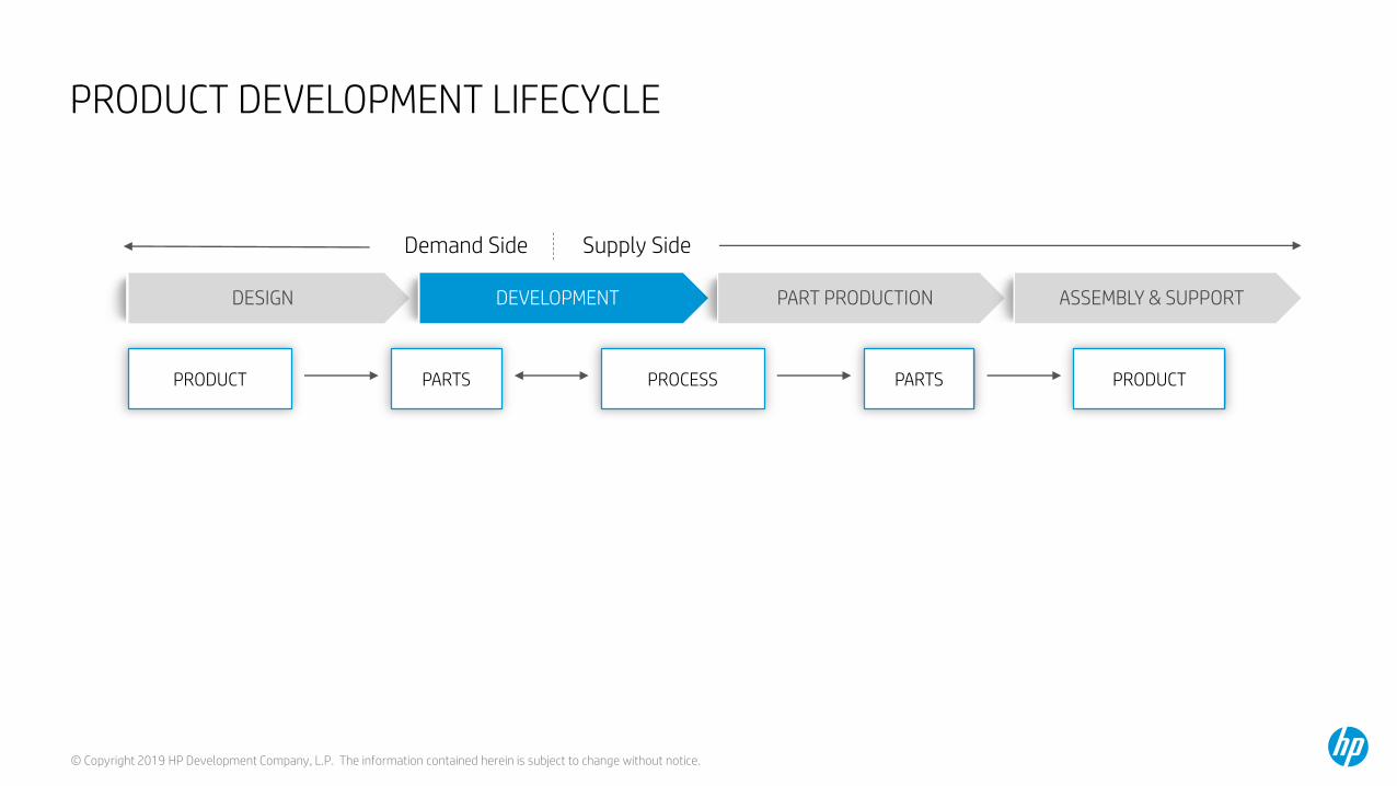
PRODUCT DEVELOPMENT LIFECYCLE: WHAT YOU WILL HEAR TODAY
DEVELOPMENT ASSEMBLY & SUPPORT
Demand Side Supply Side
PRODUCT PARTS PROCESS PARTS PRODUCT
PART PRODUCTIONDESIGN
HP MJF HANDBOOKHP 3D PROCESS
CONTROL SW
HP JET FUSION5200 SERIES 3D PRINTING
SOLUTION
HP 3D CENTRE SW

© Copyright 2019 HP Development Company, L.P. The information contained herein is subject to change without notice.
DEVELOPMENT ASSEMBLY & SUPPORT
Demand Side Supply Side
PRODUCT
PARTS Req
Assembly PROCESS & Tools
PARTS
PRODUCT
PART PRODUCTION
DESIGN
PRODUCT DEVELOPMENT LIFECYCLE
Part PROCESS & Tools
LAURASupply chain
Engineer/Manager
PETERProcess Engineer
PATRICKProduction manager
LISAMechanical
Engineer
Assembly Reqs
CHRISProgram/Product Manager
JorgeManufacturing
Engineer
JeffPart Quality
Engineer
AlexManufacturing
Quality EngineerMaria
Manufacturing Manager
RICHARDTechnical Sales
JAMESBusiness Owner

© Copyright 2019 HP Development Company, L.P. The information contained herein is subject to change without notice.
END PART PROCESS AND MATERIAL SELECTION PROCESSYou need to meet cost and quality requirements to get on Laura’s list of possible processes
LAURASUPPLY CHAIN ENGINEER / MANAGER
For a given production volume
Pick the least expensive combination of process and material
That meets your design requirements:
Dimensional tolerance consistency
Material properties consistencyLISA
MECHANICAL ENGINEER

© Copyright 2019 HP Development Company, L.P. The information contained herein is subject to change without notice.
Dimensional Requirement: which tolerances necessary for mechanisms to fit, or function. This is very dependent on the application and specific mechanism
3 ELEMENTS OF PART DIMENSIONSAll are necessary
LISAMECHANICAL ENGINEER
A. Fit requirements: there are standards for press fits, and clearance fits, and other “hole and shaft” fitting. ANSI Standard Limits and Fits (ANSI B4.1-1967,R1974). Whether a press or clearance fit is needed is dependent on the functional calculations for a specific mechanism.
B. Functional requirements: But generally, there are more functional tolerances than fit tolerances on a part. Developing the relationship between part tolerances and subsystem function is a large part of the mechanical engineers work in the development phase. This is very application dependent.
1
Geometric Dimensioning & Tolerancing or drawing standards: or how to communicate your dimensional requirements on a drawing. This is called Geometric Dimensioning and Tolerancing or GD&T. If mechanical engineers didn’t follow the same drawing rules, then nobody could understand anybody else’s drawing. ASME Y14.5 or ISO/TC213
2
Dimensional Tolerance standard: this is the standard that allows a comparison between process capabilities. ISO 286/ANSI B4.2-1978 International Tolerance Grade3

© Copyright 2019 HP Development Company, L.P. The information contained herein is subject to change without notice.
LISAMechanical Engineer
Example of standards for hole to shaft types of fits (ANSI B4.1-1967,R1974)
1. Dimensional Part Requirements for General Fit

© Copyright 2019 HP Development Company, L.P. The information contained herein is subject to change without notice.
LISAMechanical Engineer
Most dimensional requirements are about subassembly functioning. Tolerance stacking or worst case analysis for functionality is a large part of the mechanical engineer’s work in the Development Phase
1. Dimensional Part Requirements

© Copyright 2019 HP Development Company, L.P. The information contained herein is subject to change without notice.
LISAMechanical Engineer
Examples of how to communicate your requirements in a drawing
2. Geometric Dimensioning and Tolerancing
Dimension Types
1. Functionally critical dimensions: these are explicitly given a tolerance range of +N/-N2 on the dimension itself
2. Process control dimensions: these are generally dimensions which are easy to measure and which indicate whether a process is drifting or not. They may also imply that the functional dimensions are beginning to vary
3. General dimensions: the tolerance range is not explicitly stated but referred to the signature box on the drawing
Signature Box in accordance with ASME Y14.5 or ISO/TC213
Some ASME Y14.5 or ISO/TC213 symbols

© Copyright 2019 HP Development Company, L.P. The information contained herein is subject to change without notice.
LISAMECHANICAL ENGINEER
3. REMEMBER: A RELEVANT DIMENSIONAL TOLERANCE STANDARD
SINGLE TOLERANCE RANGE, E.G. ± 0.2mm
A PERCENTAGE, E.G. 2%
TOLERANCE RANGE VS. DIMENSION LENGTH

© Copyright 2019 HP Development Company, L.P. The information contained herein is subject to change without notice.
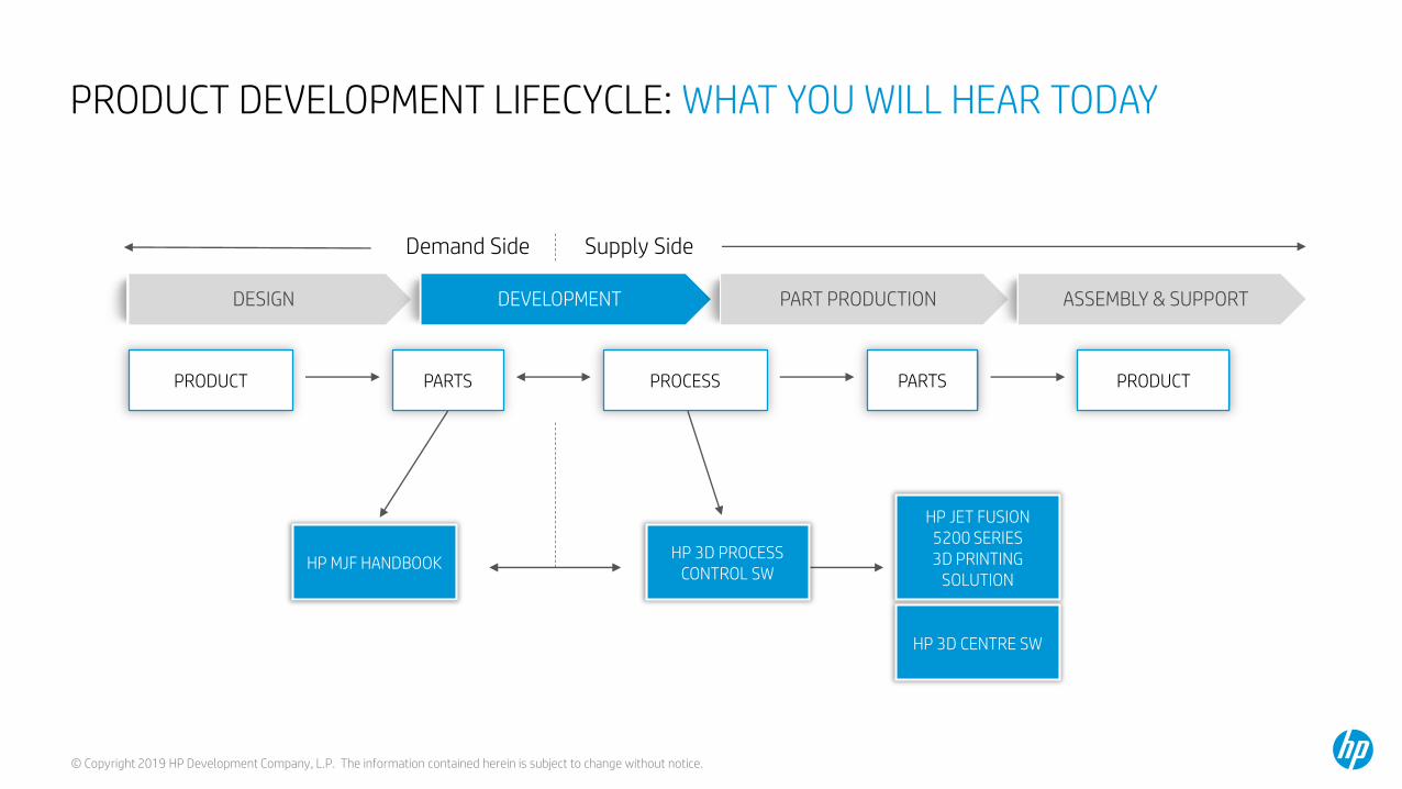
MANUFACTURING PREDICTABILITY 3. Dimensional tolerance standard
Measuring Tools
IT Grade 01 0 1 2 3 4 5 6 7 8 9 10 11 12 13 14 15 16
Material
International Tolerance Grades defined in ISO 286/ANSI B4.2-1978 , which provide a standardized reference for typical manufacturing process capability in terms of dimensional tolerance for a given dimension
Fits Large Manufacturing Tolerances
Better

© Copyright 2019 HP Development Company, L.P. The information contained herein is subject to change without notice.
The larger the specified dimension, the larger the tolerance range for accuracy
MANUFACTURING PREDICTABILITY 3. Dimensional tolerance standard
Measuring Tools
IT Grade 01 0 1 2 3 4 5 6 7 8 9 10 11 12 13 14 15 16
Material
Fits Large Manufacturing TolerancesBetter
Tolerances mmµm
Dimension (mm) Standard tolerance gradesIT12) IT22) ) IT32) ) IT42) IT52) IT6 IT7 IT8 IT9 IT10 IT11 IT12 IT13 IT143) IT153)
-
3
6
10
18
30
50
80
120
180
250
315
400
500
3
6
10
18
30
50
80
120
180
250
315
400
500
6302)
Above Up to and including
0,8
1
1
1,2
1,5
2
2,5
3,5
4,5
6
7
8
9
1,5
1,2
1,5
1,5
2
2,5
3
4
5
7
8
9
10
11
2,5
2
2,5
2,5
3
4
4
6
8
10
12
13
15
16
4
3
4
4
5
6
8
10
12
14
16
18
20
22
7
4
5
6
8
9
13
15
18
22
23
25
27
32
11
6
8
9
11
13
19
22
25
29
32
36
40
44
16
10
12
15
18
21
30
35
40
46
52
57
63
70
25
14
18
22
27
33
46
54
63
72
81
89
97
100
39
25
30
36
43
52
74
87
100
115
130
140
155
175
62
0,1
0,12
0,15
0,18
0,21
0,3
0,35
0,4
0,46
0,52
0,57
0,63
0,7
0,25
60
75
90
110
130
190
220
250
290
320
360
400
440
160
40
48
58
70
84
120
140
160
185
210
230
250
280
100
0,14
0,18
0,22
0,27
0,33
0,46
0,54
0,63
0,72
0,81
0,57
0,97
1,1
0,39
0,25
0,3
0,36
0,43
0,52
0,74
0,87
1
1,15
1,3
1,4
1,55
1,75
0,62
0,4
0,48
0,58
0,7
0,84
1,2
1,4
1,6
1,85
2,1
2,3
2,5
2,8
1
© Copyright 2019 HP Development Company, L.P. The information contained herein is subject to change without notice.
MANUFACTURING PREDICTABILITY3. Dimensional tolerance standard
Tolerance Range vs. Dimension Length
2.5
2
1.5
1
0.5
0
50 100 150 200 250 300 350 400
Tole
ran
ceR
ang
e[m
m]
IT15
IT14
IT13
IT12
IT11
Nominal dimension [mm]
The larger the specified dimension, the larger the tolerance range for that dimension

© Copyright 2019 HP Development Company, L.P. The information contained herein is subject to change without notice.
TO COMPARE BETWEEN PROCESSESBoth a process agnostic tolerance specification and the processes capability need to be specified
How well your process can meet that standard or process capability
Tolerance range vs. dimensional length
Plus

© Copyright 2019 HP Development Company, L.P. The information contained herein is subject to change without notice.P Confidential for HP internal and HP Channel under NDA use ONLY. Not for customer-facing use
1 CpK = Precision + Accuracy(Cp) + (low bias)
2Process Capability ≠Results from one machine
3Single Dimension SuccesRate ≠ Part Yield
REMEMBER: !

© Copyright 2019 HP Development Company, L.P. The information contained herein is subject to change without notice.
PROCESS CAPABILITY OR CPK is the statistical probability of a process meeting a specFor a process to be capable, it needs to be both repeatable (precise) and centered
• ACCURACY = how close a measurement value is to the specified nominal (also called bias)
• PRECISION = how close multiple measurements are to each other (statistically measured as Cp)
• CAPABILITY = the statistical probability of a dimension being within its tolerance range
• CAPABILITY = Cpk = Cp *(1-(bias/0.5)) = has a statistical equivalent “sigma”
LOW BIAS AND GOOD CP SO CPK IS GOOD
BOTH, accurate and precise
GOOD BIAS (LOW)BUT HIGH VARIABILITY
ACCURATE, but not precise
GOOD CP (LOW VARIABILITY) BUT HIGH BIAS
PRECISE, but not accurate

© Copyright 2019 HP Development Company, L.P. The information contained herein is subject to change without notice.
MANUFACTURING PREDICTABILITYSigma or Cpk is a dimensional success rate. Part yield is different
NOTES:
• Cpk and sigma are metrics for a
specific dimension being good
• For a part to be good, all the specified
dimensions need to be good
• Yield is a part metric and could be
calculated as the statistical sum of
probable dimensional tolerance
failures + some estimation for
cosmetic failures or other.
~Part Yield fora part with
10 dimensions
Dimensions permillion outside
of spec
Dimensions persuccess rate
(%)Sigma Cpk
68.27000
95.45000
98.00000
99.73000
99.99370
99.99966
99.99997
317,300
45500
20000
2700
63
3.4
0.6
0.33
0.67
0.79
1.00
1.33
1.50
1.67
2.20%
62.77%
81.71%
97.33%
99.94%
100.00%
1
2
3
4
5
6
Sigma or Cpk is equivalent to statistical probability of a percentage of population of one specific dimension being good
© Copyright 2019 HP Development Company, L.P. The information contained herein is subject to change without notice.
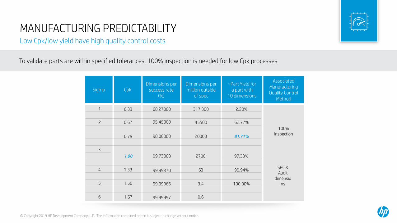
MANUFACTURING PREDICTABILITY Low Cpk/low yield have high quality control costs
To validate parts are within specified tolerances, 100% inspection is needed for low Cpk processes
~Part Yield fora part with
10 dimensions
Dimensions permillion outside
of spec
Dimensions persuccess rate
(%)Sigma Cpk
68.27000
95.45000
98.00000
99.73000
99.99370
99.99966
99.99997
317,300
45500
20000
2700
63
3.4
0.6
0.33
0.67
0.79
1.00
1.33
1.50
1.67
2.20%
62.77%
81.71%
97.33%
99.94%
100.00%
1
2
3
4
5
6
AssociatedManufacturingQuality Control
Method
100% Inspection
SPC & Audit
dimensions

© Copyright 2019 HP Development Company, L.P. The information contained herein is subject to change without notice.
GENERAL DIMENSION PROCESS CAPABILITY COMPARISON at Cpk=1.33
Measuring Tools
IT Grade 01 0 1 2 3 4 5 6 7 8 9 10 11 12 13 14 15 16
Material
Fits Large Manufacturing Tolerances
17 18
Typical 3D Processes
Programmedmachining
Precision molding andcritical dimensions
Hard Steel
General PlasticMolding
Soft Steel
Prototype moldingTypically
Aluminum
© Copyright 2019 HP Development Company, L.P. The information contained herein is subject to change without notice.
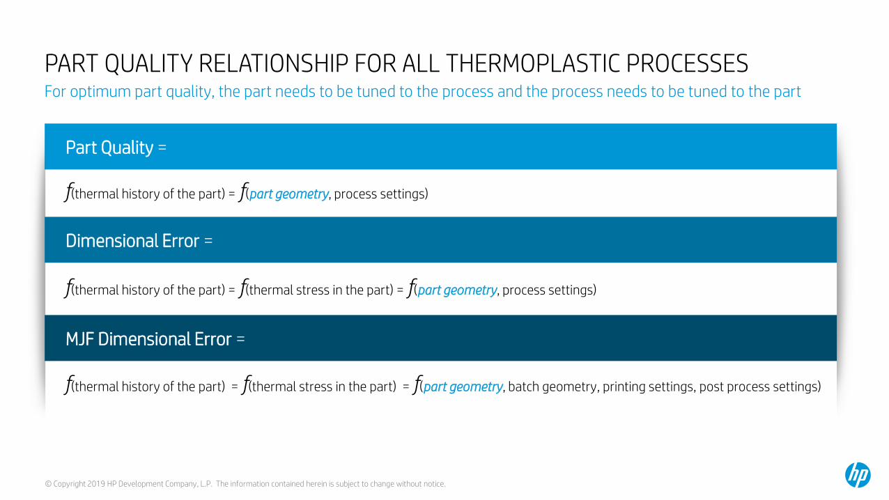
Part Quality =
PART QUALITY RELATIONSHIP FOR ALL THERMOPLASTIC PROCESSESFor optimum part quality, the part needs to be tuned to the process and the process needs to be tuned to the part
f(thermal history of the part) = f(part geometry, process settings)
Dimensional Error =
f(thermal history of the part) = f(thermal stress in the part) = f(part geometry, process settings)
MJF Dimensional Error =
f(thermal history of the part) = f(thermal stress in the part) = f(part geometry, batch geometry, printing settings, post process settings)

© Copyright 2019 HP Development Company, L.P. The information contained herein is subject to change without notice.
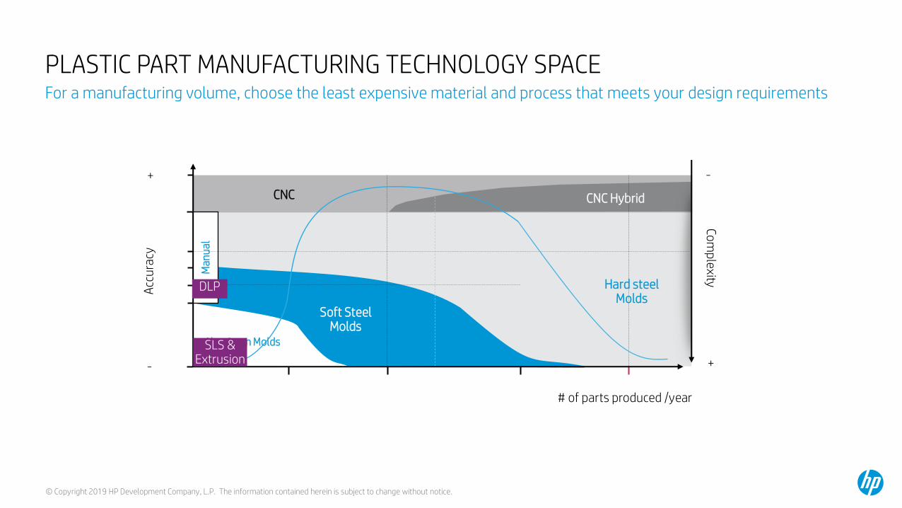
PLASTIC PART MANUFACTURING TECHNOLOGY SPACEFor a manufacturing volume, choose the least expensive material and process that meets your design requirements
# of parts produced /year
CNCCo
mp
lexity+
-
Aluminum Molds
Man
ual
CNC Hybrid
Soft Steel Molds
Hard steel Molds
Acc
ura
cy
-
+

© Copyright 2019 HP Development Company, L.P. The information contained herein is subject to change without notice.
PLASTIC PART MANUFACTURING TECHNOLOGY SPACEFor a manufacturing volume, choose the least expensive material and process that meets your design requirements
# of parts produced /year
CNCCo
mp
lexity+
-
Aluminum Molds
Man
ual
CNC Hybrid
Soft Steel Molds
Hard steel Molds
Acc
ura
cy
-
+
Mold begins to wear and quality drops
Low Thermal Mass = inconsistent temperatures and thermal stress

© Copyright 2019 HP Development Company, L.P. The information contained herein is subject to change without notice.
PLASTIC PART MANUFACTURING TECHNOLOGY SPACEFor a manufacturing volume, choose the least expensive material and process that meets your design requirements
# of parts produced /year
CNCCo
mp
lexity+
-
Aluminum Molds
Man
ual
CNC Hybrid
Soft Steel Molds
Hard steel Molds
Acc
ura
cy
-
+
Features wear and steel hardening causes non-uniformity & thermal stress
Time consuming & expensive qualification
Fine features wear

© Copyright 2019 HP Development Company, L.P. The information contained herein is subject to change without notice.
Total Time = 2-4 weeks• Remove the mold• Machine in changes from
serious deviations of critical dimensions
• Assemble Mold• Install mold into molding
machine• Run while tuning time and
pressure until you get reasonable variability
• Run quantity of parts• Measure• Ship • Sometimes very critical
dimensions are reworked/machined
Iteration 3a,b,c: Dimension by dimension machining of bias, Window study
PLASTIC INJECTION MOLDING DEVELOPMENT PHASE WORKFLOW: TUNING THE PROCESSAssume soft steel molds tuned to IT13 or better with ~10 critical dimensions
Total Time = ~8 weeks• Design Mold• Fabricate Mold• Assemble Mold• Install mold into molding
machine• Run• Measure all dimensions once
and all critical dimension statistically
Total Time = ~ 4 weeks• Remove the mold• Machine in changes to design &
critical dimension bias• Assemble Mold• Install mold into molding machine• Run• Measure• Sometimes, iterate for very fine
dimensions• Complete window study to
determine best pressures, time and temperature
• Run quantity of parts• Measure• Ship
R&D: Test, re-design, release
Manufacturing:Assemble Product
Iteration 2: Reduce Variability/parameter tuning
Iteration 1: First Article: General diimensions
FirstRelease

© Copyright 2019 HP Development Company, L.P. The information contained herein is subject to change without notice.
Iteration 3: Dimension by dimension machining of bias, Window study
GENERAL CAPABILITY: INJECTION MOLDING WORKFLOW WITH SOFT STEEL MOLDTime consuming and costly iterations
Total Time = ~8 weeks
Iteration 2: Reduce Variability / parameter tuning
Total Time = ~4 weeks
Iteration 1First Article: General diimensions
Molding machine installation calibrations
PartRelease
Molding machine factory calibrations
Total Time = 2-4 weeks
Cpk = ~0.3 to 0.6IT13
Cpk = ~1IT13
Or IT 13-14 with Cpk 1.33
Cpk = ~1.33IT13

© Copyright 2019 HP Development Company, L.P. The information contained herein is subject to change without notice.
PLASTIC PART MANUFACTURING TECHNOLOGY SPACEFor a manufacturing volume, choose the least expensive material and process that meets your design requirements
# of parts produced /year
CNCCo
mp
lexity+
-
Aluminum Molds
Man
ual
CNC Hybrid
Soft Steel Molds
Hard steel Molds
Acc
ura
cy
-
+
Features wear and steel hardening causes non-uniformity & thermal stress
Time consuming & expensive qualification
Fine features wear

© Copyright 2019 HP Development Company, L.P. The information contained herein is subject to change without notice.
PLASTIC PART MANUFACTURING TECHNOLOGY SPACEFor a manufacturing volume, choose the least expensive material and process that meets your design requirements
# of parts produced /year
CNCCo
mp
lexity+
-
Aluminum Molds
Man
ual
CNC Hybrid
Soft Steel Molds
Hard steel Molds
Acc
ura
cy
-
+
Limited geometries to parts which allow the mold to open
Time consuming & expensive qualification

© Copyright 2019 HP Development Company, L.P. The information contained herein is subject to change without notice.
PLASTIC PART MANUFACTURING TECHNOLOGY SPACEFor a manufacturing volume, choose the least expensive material and process that meets your design requirements
# of parts produced /year
CNCCo
mp
lexity+
-
Aluminum Molds
Man
ual
CNC Hybrid
Soft Steel Molds
Hard steel Molds
Acc
ura
cy
-
+
Human error
Labor intensive

© Copyright 2019 HP Development Company, L.P. The information contained herein is subject to change without notice.
PLASTIC PART MANUFACTURING TECHNOLOGY SPACEFor a manufacturing volume, choose the least expensive material and process that meets your design requirements
# of parts produced /year
CNCCo
mp
lexity+
-
Aluminum Molds
Man
ual
CNC Hybrid
Soft Steel Molds
Hard steel Molds
Acc
ura
cy
-
+
Limited productivity for complex geometries forces hybrid model

© Copyright 2019 HP Development Company, L.P. The information contained herein is subject to change without notice.
PLASTIC PART MANUFACTURING TECHNOLOGY SPACEFor a manufacturing volume, choose the least expensive material and process that meets your design requirements
# of parts produced /year
CNCCo
mp
lexity+
-
Aluminum Molds
Man
ual
CNC Hybrid
Soft Steel Molds
Hard steel Molds
Acc
ura
cy
-
+
SLS &Extrusion
DLP

© Copyright 2019 HP Development Company, L.P. The information contained herein is subject to change without notice.
PLASTIC PART MANUFACTURING TECHNOLOGY SPACEFor a manufacturing volume, choose the least expensive material and process that meets your design requirements
# of parts produced /year
CNCCo
mp
lexity+
-
Aluminum Molds
Man
ual
CNC Hybrid
Soft Steel Molds
Hard steel Molds
Acc
ura
cy
-
+
DLP
Shrinkage during curing
Single part productivity
Limited geometry & materials do not emulate other processes
© Copyright 2019 HP Development Company, L.P. The information contained herein is subject to change without notice.
PLASTIC PART MANUFACTURING TECHNOLOGY SPACEFor a manufacturing volume, choose the least expensive material and process that meets your design requirements
# of parts produced /year
CNCCo
mp
lexity+
-
Aluminum Molds
Man
ual
CNC Hybrid
Soft Steel Molds
Hard steel Molds
Acc
ura
cy
-
+
SLS &Extrusion
DLP

© Copyright 2019 HP Development Company, L.P. The information contained herein is subject to change without notice.
PLASTIC PART MANUFACTURING TECHNOLOGY SPACEFor a manufacturing volume, choose the least expensive material and process that meets your design requirements
# of parts produced /year
CNCCo
mp
lexity+
-
Aluminum Molds
Man
ual
CNC Hybrid
Soft Steel Molds
Hard steel Molds
Acc
ura
cy
-
+
SLS &Extrusion
DLPExtruder Resolution vs. time to part & z-property tradeoff
Point process & Poor ratio of Productivity / Acquisition Cost

© Copyright 2019 HP Development Company, L.P. The information contained herein is subject to change without notice.
PLASTIC PART MANUFACTURING TECHNOLOGY SPACEFor a manufacturing volume, choose the least expensive material and process that meets your design requirements
# of parts produced /year
CNCCo
mp
lexity+
-
Aluminum Molds
Man
ual
CNC Hybrid
Soft Steel Molds
Hard steel Molds
Acc
ura
cy
-
+
SLS &Extrusion
DLP“On-Off Energy” means accuracy vs. z-property tradeoff
Point process & Poor ratio of Productivity / Acquisition Cost

© Copyright 2019 HP Development Company, L.P. The information contained herein is subject to change without notice.
PLASTIC PART MANUFACTURING TECHNOLOGY SPACEFor a manufacturing volume, choose the least expensive material and process that meets your design requirements
# of parts produced /year
CNCCo
mp
lexity+
-
Aluminum Molds
Man
ual
CNC Hybrid
Soft Steel Molds
Hard steel Molds
Acc
ura
cy
-
+
HP MJF
SLS &Extrusion
DLP
CNC +HP MJF

© Copyright 2019 HP Development Company, L.P. The information contained herein is subject to change without notice.
PLASTIC PART MANUFACTURING TECHNOLOGY SPACEFor a manufacturing volume, choose the least expensive material and process that meets your design requirements
# of parts produced /year
CNCCo
mp
lexity+
-
Aluminum Molds
Man
ual
CNC Hybrid
Soft Steel Molds
Hard steel Molds
Acc
ura
cy
-
+
HP MJF + HP MJF Complexity Parts
SLS &Extrusion
DLP
CNC +HP MJF

© Copyright 2019 HP Development Company, L.P. The information contained herein is subject to change without notice.
HP 3D Process Control SoftwareEnabling better part tolerancing

© Copyright 2019 HP Development Company, L.P. The information contained herein is subject to change without notice.
PLASTIC PART MANUFACTURING TECHNOLOGY SPACEFor a manufacturing volume, choose the least expensive material and process that meets your design requirements
# of parts produced /year
CNCCo
mp
lexity+
-
Aluminum Molds
Man
ual
CNC Hybrid
Soft Steel Molds
Hard steel Molds
Acc
ura
cy
-
+
HP MJF + HP MJF Complexity Parts
SLS &Extrusion
DLP
CNC +HP MJF
Difficult or impossible to mold

© Copyright 2019 HP Development Company, L.P. The information contained herein is subject to change without notice.
1 part
Traditional Design & Mfg 3D printed integrated design
Fan ventilator lower side
3D printed part
EPDM adhesive seal right
EPDM adhesive seal left
Screw 13x Sealing O-ringFan ventilator upper side
EPDM adhesive seal left
COMBINED PARTS IN FLUID MANAGEMENT: COST COMPETITIVE
6 parts + 13 screws + Assy & testingPart combination results in lower cost and Better
quality/performance

© Copyright 2019 HP Development Company, L.P. The information contained herein is subject to change without notice.
PART QUALITY & COST: HP MJF HANDBOOKFor optimum part quality, the part needs to be tuned to the process and the process needs to be tuned to the part
www.hp.com/go/MJFHandbook
Want to talk to someone about your design specifically?https://enable.hp.com/us-en-3d-prints-plastics-cwu
1-877-468-8369

Summary
3D Printing is entering an era where it can compete up to reasonable production volumes against injection molding and this requires the printing device to have a good ratio of Productivity/Acquisition Cost
A development phase cannot be skipped with any process, but digital process development can be much shorter and much less expensive
The chosen part fabrication process must meet the design requirements for accuracy, and the design will always need to be optimized to the chosen part fabrication process
3D Printing can disrupt product development cycles and the Return on Investment of new products•Designing for and fabricating with 3D Printing, with its shorter development cycles, can open more flexible product development processes, that include such concepts as bridge manufacturing. •Additional functionality or product differentiation can also be considered.
© Copyright 2019 HP Development Company, L.P. The information contained herein is subject to change without notice.

HP Confidential for HP internal and HP Channel under NDA use ONLY. Not for customer-facing use