ANSI B4.1-1967 Preferred Limits and Fits for Cylindrical Parts
25
~ m 2575532 0081582 234 m ANSI 84.1-1967 4 January 1972 ACCEPTANCE NOTICE The above Industry Standardization Document was adopted on 4 January 1972 and i s approved for use by the DOO. The indicated industry groups have furnished the clearances required by exist- ing regulations. Copies of the document are stocked by DoD Single Stock Point, U.S. Naval Publi- cations and Forms Center, Philadelphia, Pennsylvania 19120, for issue to DoD activities only. Title of Document: Preferred Limits and Fits for Cylindrical Parts Date of Specific Issue Adopted: 18 September 1967 - Plus Errata Releasing Industry Group: The American Society of Mechanical Engineers Custodians: Army - MU Navy - SH Air Force - 70 Military Coordinating Activity: Air Force - 70 Project No. MISC-0596 P No part of this document may be reproduced in any form, in an electronic retrieval system or otherwise. without the prior writtun permission of the publisher. THE AMERICAN SOCIETY OF MECHASICAL ENGINEERS Copyrrghr, Q. 1967, by Printed in U.S.A. COPYRIGHT 2003; American Society of Mechanical Engineers Document provided by IHS Licensee=Cummins Engine/1232502100, User=, 10/17/2003 04:52:58 MDT Questions or comments about this message: please call the Document Policy Group at 1-800-451-1584. --``,````,````,``,`````,,````,,-`-`,,`,,`,`,,`---
Transcript of ANSI B4.1-1967 Preferred Limits and Fits for Cylindrical Parts
~
m 2575532 0081582 234 m
ANSI 84.1-1967 4 January 1972
ACCEPTANCE NOTICE
The above Industry Standardization Document was adopted on 4 January 1972 and i s approved for use by the DOO. The indicated industry groups have furnished the clearances required by exist- ing regulations. Copies of the document are stocked by DoD Single Stock Point, U.S. Naval Publi- cations and Forms Center, Philadelphia, Pennsylvania 19120, for issue to DoD activities only.
T i t le of Document: Preferred Limits and Fi ts for Cylindrical Parts
Date of Specific Issue Adopted: 18 September 1967 - Plus Errata
Releasing Industry Group: The American Society of Mechanical Engineers
Custodians: Army - MU Navy - SH Air Force - 70
Military Coordinating Activity: Air Force - 70
Project No. MISC-0596
P
No part of this document may be reproduced in any form, in an electronic retrieval system or otherwise. without the prior
writtun permission of the publisher.
THE AMERICAN SOCIETY OF MECHASICAL ENGINEERS Copyrrghr, Q. 1967, by
Printed in U.S.A.
COPYRIGHT 2003; American Society of Mechanical Engineers
Document provided by IHS Licensee=Cummins Engine/1232502100, User=, 10/17/200304:52:58 MDT Questions or comments about this message: please call the DocumentPolicy Group at 1-800-451-1584.
--``,````,````,``,`````,,````,,-`-`,,`,,`,`,,`---

U S A S T A N D A R D
Preferred Limits and Fits for Cylindrical Parts
USAS 84.1-1967 (R1974)
Note For soft conversion of nominal dimensions and limits given
in this standard, 1 inch = 25.4 mm. National Standard 2210.1-1 972, Metric Practice Guide.
For explanation of conversion techniques see American
REAFFIRMED 1994
FOR CURRENT COMMITIEE PERSONNEL PLEASE SEE M M E MANUAL AS-1 1
SpOndoP
The American Society of Mechonicol Engineers
T H E A M E R I C A N S O C I E T Y O F M E C H A N I C A L E N G I N E E R S
United Engineering Center 345 East 47th Street N e w Y o r k , N. Y. 10017
COPYRIGHT 2003; American Society of Mechanical Engineers
Document provided by IHS Licensee=Cummins Engine/1232502100, User=, 10/17/200304:52:58 MDT Questions or comments about this message: please call the DocumentPolicy Group at 1-800-451-1584.
--``,````,````,``,`````,,````,,-`-`,,`,,`,`,,`---
标准分享网 www.bzfxw.com 免费下载
www.bzfxw.com
toreword
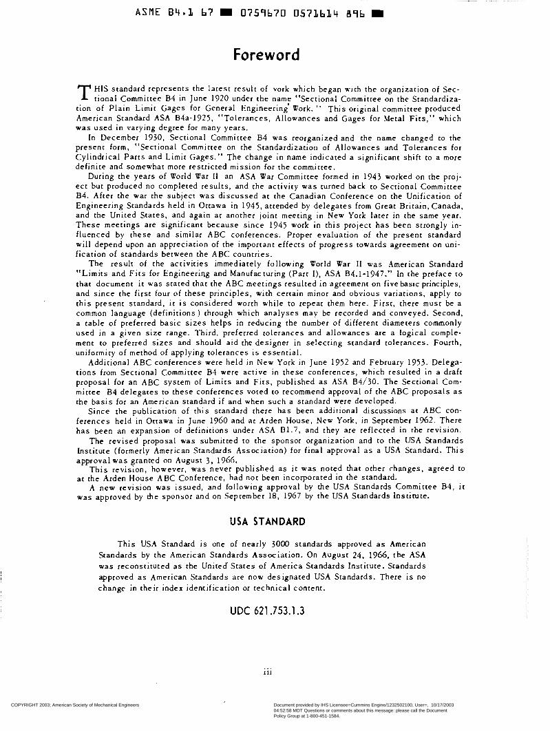
T HIS standard represents the latest result of vork which began w i t h the organization of Sec- tional Committee B4 in June 1920 under the namf “Sectional Committee on the Standardiza-
tion of Plain Limit Gages for General Engineering Work. ” This original committee produced American Standard ASA B4a-1925, “Tolerances, Allowances and Gages for Metal Fi ts ,” which was used i n varying degree for many years.
In December 1930, Sectional Committee B4 was reorganized and the name changed to the present form, “Sectional Committee on the Standardization of Allowances and Tolerances for Cylindrical Parts and Limit Gages.” The change in name indicated a significant shift to a more definite and somewhat more restricted mission for the committee.
During the years of World War II an ASA War Committee formed i n 1943 worked on the proj- ec t but produced no completed results, and t h e activity was turned back to Sectional Committee B4. After the war the subject was discussed at the Canadian Conference on the Unification of Engineering Standards held i n Ottawa in 1945, attended by de lega tes from Great Britain, Canada, and the United States, and again at another joint meeting in New York later in the same year. These meetings are significant because since 1945 work i n this project has been strongly in- f luenced by these and similar ABC conferences. Proper evaluation of the present standard will depend upon an appreciation of the important effects of progress towards agreement on uni- fication of standards between the ABC countries.
The resul t of the activities immediately following World War II was American Standard “Limi ts and F i t s for Engineeriw and Manufacturing (Part I ) , ASA B4.1-1947.” In the preface to that document i t was stated that the ABC meetings resulted in agreement on five baslc principles, and since the first four of these pr inciples , w i th certain minor and obvious variations, apply to th i s p resent s tandard , i t is considered worth wh i l e to repeat them here. First , there m u s t be a common language (definitions) through which analyses may be recorded and conveyed. Second, a table of preferred basic sizes helps i n reducing the number of different diameters commonly used in a given size range. Third, preferred tolerances and allowances are a logical comple- ment to preferred sizes and should aid the designer i n se!ecting standard tolerances. Fourth, uniformity of method of applying tolerances is essent ia l .
Additional ABC conferences were held i n N e w York i n June 1952 and February 1953. Delega- t ions from Sectional committee B4 were active in these conferences, which resulted in a draft proposal for an ABC system of Limits and Fi ts , publ ished as ASA B4/30. The Sectional Com- mittee B4 de lega tes to these conferences voted to recommend approval of the ABC proposals as t h e bas i s for an American standard i f and when such a standard were developed.
Since the publication of this standard there h a s been additional discussions at ABC con- ferences held in Ottawa in June 1960 and at Arden House, New York, in September 1962. There has been a n expansion of definit ions under ASA 81 .7 , and they are reflected in the revision.
The revised proposal was submitted to the sponsor organization and to the USA Standards Institute (formerly American Standards Association) for final approval as a USA Standard. This approval was granted on August 3. 1966.
This revis ion, however , was never publ ished as i t was noted that o ther rhanges, agreed CO a t the Arden House ABC Conference, had not been incorporated i n the standard.
A new revision was issued, and following approval by the USA Standards Committee B4, i t was approved by the sponsor and on September 18, 1967 by the USA Standards Insti tute.
USA STANDARD
T h i s USA Standard is one of nearly 3000 standards approved as American s tandards by the American Standards Asscciation. On August 24, 1966, t h e ASA was reconsti tuted as the United States of America standards Insti tute. Standards approved as American Standards are now designated USA Standards. There is no change in their . index identification or technical content.
UDC 621.753.1.3
111 ...
COPYRIGHT 2003; American Society of Mechanical Engineers
Document provided by IHS Licensee=Cummins Engine/1232502100, User=, 10/17/200304:52:58 MDT Questions or comments about this message: please call the DocumentPolicy Group at 1-800-451-1584.
--``,````,````,``,`````,,````,,-`-`,,`,,`,`,,`---

www.bzfxw.com
ASME B'4.3 67 m 0759670 0573635 722 m
USA Standards Committee B4, Standardization of Allowances and Tolerances for Cylindrical Parts and Limit Gages
OFFICERS
G. H. Stimson, Chairman
COMMITTEE MEMBERS
AMERICAN SOCIETY FOR QUALITY CONTROL R. J . Morris, International Harvester Co., Chicago, I11
AMERICAN SOCIETY OF MECHANICAL ENGINEERS, THE Z. R. Bliss, Brown University, Providence, R. I. R: T. Woythal, Kearney & Trecker Corp., Milwaukee, Wisconsin
AMERICAN SOCIETY OF TOOL AND MANUFACTURING ENGINEERS G. H. Stimson, Greenfield Tap and Die, Division of United-Greenfield Corp., Greenfield, Mass.
ANTI-FRICTION BEARING MANUFACTURERS ASSOCIATION, INC. H. L. Potter, The Fafnir Bearing Co., N e w Britain, Com.
BUSINESS EQUIPMENT MANUFACTURERS ASSOCIATION A. E. Mall, Interhational Business Machines Corp., Endicott, N. Y.
METAL CUTTING TOOL INSTITUTE A. F. Miller, Jr . , Wells Tool Co., Greenfield, Mass.
NATIONAL ELECTRICAL MANUFACTURERS ASSOCIATION F. V. Kupchak, Westinghouse Electric Corp., Pittsburgh, Pa. L. D. Price, Alternate, National Electrical Mfgrs. Association, New York, N. Y.
NATIONAL MACHINE TOOL BUILDERS' ASSOCIATION F. S. Blackall, III, The Taft-Peirce Mfg. Co., Woonsocket, R. I.
SOCIETY OF AUTOMOTIVE ENGINEERS, INC. R. F. Holmes, General Motors Technical Center, Warren, Michigan
SPORTING ARMS 8z AMMUNITIONS MANUFACTURERS ASSOCIATION J . F. Walsh, Olin Mathieson Chemical Co., New Haven, Conn.
U. S. DEPT. OF THE ARMY C. B. Keane, Frankford Arsenal, Philadelphia, Pa.
U. S. DEPT. OF COMMERCE I. H. Fullmer, National Bureau of Standards, Washington, D. C.
U. S. DEPT. OF THE NAVY Code 609.3C, Bureau of Ships, Navy Dept., Washington, D. C. J , C. Reid, Alternate, Bureau of Ships, Navy Dept., Washington, D. C.
U. S. MACHINE, CAP, WOOD AND TAPPING SCREW BUREAUS H. G. hluenchinger, Holo-Krome Screw Corp., Hartford, Com.
INDIVIDUALMEMBERS W. S. Brown, Roanoke, Virginia H. W. Fahrlander, Sr., St. Pet.ersburg, Fla. W. H. Gourlie, West Hartford, Conn. R. E. W. Harrison, Harrison Engineering Services, Inc., Washington, D. c. Ronald Jones, Westinghouse Electric Corp., Philadelphia, Pa. A. O. Schmidt, The Pennsylvania State University, University Park, Pa. L. F. Spector, Hitchcock Publishing Co., Wheaton, Ill. H. D. Stover, Timken Roller Bearing Co., Canton, Ohio
iv
COPYRIGHT 2003; American Society of Mechanical Engineers
Document provided by IHS Licensee=Cummins Engine/1232502100, User=, 10/17/200304:52:58 MDT Questions or comments about this message: please call the DocumentPolicy Group at 1-800-451-1584.
--``,````,````,``,`````,,````,,-`-`,,`,,`,`,,`---
标准分享网 www.bzfxw.com 免费下载
www.bzfxw.com
ASME B4.L 67 D 0757b70 057LbLb 669 D
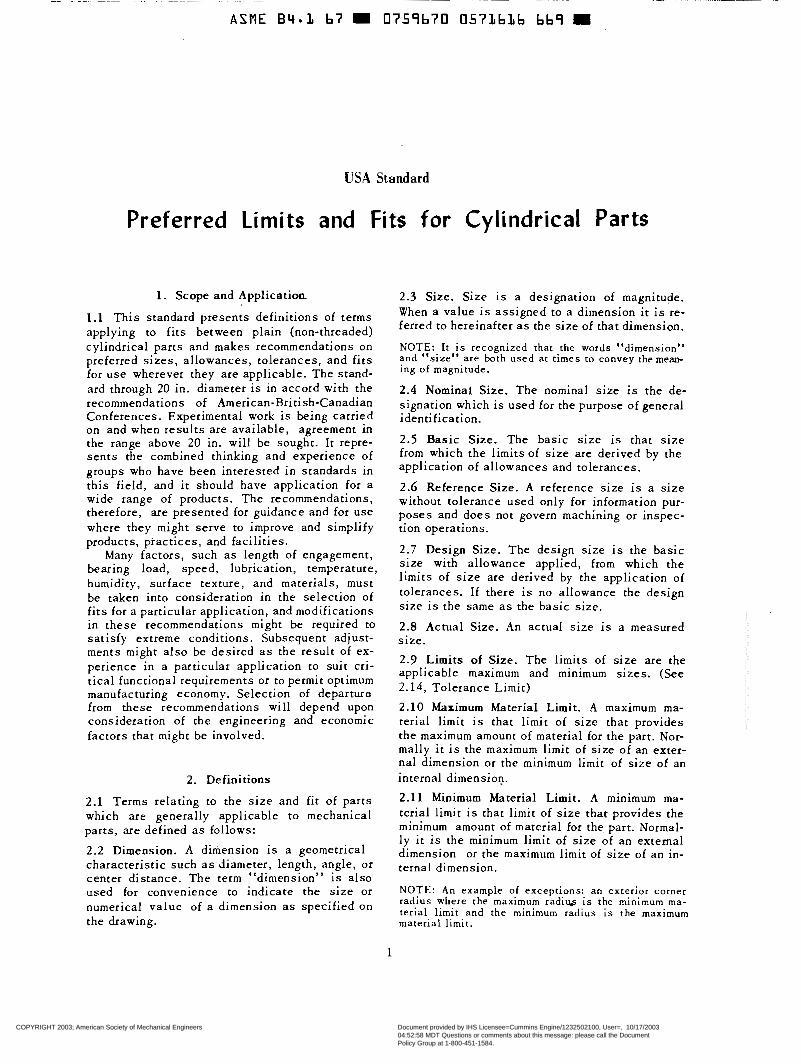
USA Standard
Preferred Limits and Fits for Cylindrical Parts
1. Scope and Application.
1.1 This s tandard p resents def in i t ions of terms applying to fits between plain (non-threaded) cylindrical parts and makes recommendations on preferred s izes , a l lowances, to lerances, and fits for u s e wherever they are applicable. The stand- ard through 20 in. diameter i s in accord with the recommendations of American-British-Canadian Conferences. Experimental work i s being carried on and when resul ts are avai lable , agreement in the range above 20 in. will be sought. It repre- sents the combined thinking and experience of groups who have been interested in standards in this f ie ld , and i t should have application for a wide range of products. The recommendations, therefore, are presented for guidance and for use where they might serve to improve and simplify products , pract ices , and faci l i t ies .
Many factors , such as length of engagement, bearing load, speed, lubrication, temperature, humidity, surface texture, and materials, must be taken into consideration in the selection of fits for a particular application, and modifications in these recommendations might be required to sat isfy extreme condi t ions. Subsequent adjust- ments might a lso be desired as the resul t of ex- per ience in a par t icular appl icat ion to suit cri- t ical functional requirements or to permit optimum manufacturing economy. Selection of departure from these recommendations will depend upon considerat ion of the engineering and economic factors that might be involved.
2. Definitions
2.1 Terms relating to t he s i ze and f i t of par t s which are generally applicable to mechanical parts, are defined as follows:
2.2 Dimension. A dimension i s a geometrical charac te r i s t ic such a s diameter, length, angle, or center dis tance. The term “dimension” is a lso used for convenience to ind ica t e t he s i ze or numerical value of a dimension as specif ied o n the drawing.
2.3 Size. Size i s a designation of magnitude, When a value is a s s i g n e d to a dimension it is re- ferred to hereinafter as the s i ze of that dimension.
NOTE: It is r e c o g n i z e d that the words “dimension” a n d “ s i z e ” a r e b o t h u s e d a t t i m e s to convey the mean- i n g of magnitude.
2.4 Nominal Size. The nominal s ize is the de- s ignat ion which is used for the purpose of general identification.
2 .5 Basic Size. The bas i c s i ze i s t ha t s i ze from which the l imits of s ize a re der ived by the appl icat ion of a l lowances and tolerances.
2.6 Reference Size. A r e fe rence s i ze i s a size without tolerance used only for information pur- poses and does not govern machining or inspec- tion operations.
2.7 Design Size. T h e d e s i g n s i z e i s t h e b a s i c size with allowance applied, from which the l imits of size are derived by the application of tolerances. If there i s no a l lowance the des ign s i z e i s t h e s a m e a s the bas i c s i ze .
2.8 Actual Size. An a c t u a l s i z e i s a measured s ize .
2.9 Limits of Size. The l imi t s of s i ze a r e t he appl icable maximum and minimum sizes. (See 2.14, Tolerance Limit)
2.10 Maximum Material Limit. A maximum ma- terial l imit is that l imit of s ize that provides t h e maximum amount of material for the part. Nor- mally i t i s t h e maximum limit of s i z e of an exter- nal dimension or the minimum limit of s i z e of an internal dimension.
2.11 Minimum Material Limit. A minimum ma- terial l imit is that limit of size that provides the minimum amount of material for the part. Normal- l y i t is the minimum limit of s i z e of an external dimension or the maximum limit of size of an in- ternal dimension.
NOTE: An example of except ions: an exter ior corner radius where the m a x i m u m r a d i w i s the minimum ma- terial l imit and the minimum radius is the maximum material l imit .
1
COPYRIGHT 2003; American Society of Mechanical Engineers
Document provided by IHS Licensee=Cummins Engine/1232502100, User=, 10/17/200304:52:58 MDT Questions or comments about this message: please call the DocumentPolicy Group at 1-800-451-1584.
--``,````,````,``,`````,,````,,-`-`,,`,,`,`,,`---

www.bzfxw.com
USA STANDARD
2.12 Allowance, An allowance is a prescribed difference between the maximum-material-limits of mating parts. It is the minimum clearance (pos- itive allowance) or maximum interference (nega- tive allowance) between such parts. (See 2.17 Fit.) 2.13 Tolerance. A tolerance i s the total permis- sible variation of a size. The tolerance i s the difference between the limits of size. NOTE: The plural term "tolerances" i s sometimes used to denote the permissible variations from the
pressed bilaterally. In this sense the term i s identi- specified or design size, when the tolerance i s ex-
cal to "Tolçrance limit."
2.14 Tolerance Limit. A tolerance limit is the variation, positive or negative, by which a size i s permitted to depart from the design size. (See 2.9, Limits of Size) 2.15 Unilateral Tolerance. A unilateral toler- ance i s a tolerance in which variation is per- mitted only in one direction from the design size. 2.16 Bilateral Tolerance. A bilateral tolerance is a tolerance in which variation i s permitted in both directions from the design size. 2.17 Fit. Fit i s the general term used to signify the range of tightness or looseness which may result from the application of a specific combina- tion of allowances and tolerances in the design of mating parts. 2.18 Actual Fit. The actual fit between two mating parts i s the relation existing between them with respect to the amount of clearance or interference that i s present when they are as- sembled. NOTE: Fits are of three general types: clearance, transition, and interference.
2.19 Clearance Fit. A clearance fit i s one having limits of size so prescribed that a clear- ance always results when mating parts are as- sembled. 2.20 Interference Fit. An interference fit i s one having .limits of size so prescribed that an inter- ference always results when mating parts are assembled. 2.21 Transition Fit. A transition fit i s one having limits of size so prescribed that either a clearance or an interference may result when mating parts ace assembled. 2.22 Unilateral Tolerance System. A design plan which uses only unilateral tolerances i s known as a unilateral tolerance system.
2.23 Bilateral Tolerance System. A design plan which uses only bilateral tolerances i s known as a bilateral tolerance system.
2.24 Basic Hole System. A basic hole system is a system of fits in which the design size of the hole i s rhe basic size and the allowance, if any, is applied to the shaft.
2.25 Basic Shaft System. A basic shaft system i s a system of fits in which the design size of the shaft i s the basic size and the allowance, if any, i s applied to the hole.
3. Preferred Basic Sizes '
In specifying fits, the basic size of mating parts shall be chosen from the following tables (one for fractional and one for decimal sizes) whenever possible. All dimensions are given in inches.
1/64 1/32 1/16 3/32 1/8 5/3 2 3/16 1/4 5/16 3/8 7/16 1/2 9/16 5/8 11/16 3/4 7/8
1 :/4 1 1/2 1 3/4 2 2 1/4 2 1/2 2 3/4 3 3 1/4 3 1/2 3 3/4
1
4 4 1/4 4 1/2 4 3/4
TABLE 1
Preferred Basic Sizes Fractional
0.015625 0.03125 0.0625 0.09375 0.1250 O. 15625 0.1875 0.2500 0.3125 0.3750 0.4375 0.5000 0.5625 0.6250 0.6875 0.7500 0.8750 1.0000 1.2500 1.5000 1.7500 2.0000 2.2500 2.5000 2.7500 3.0000 3.2500 3.5000 3.7500 4.0000 4.2500 4.5000 4.7500
5 5 1/4 5 1/2 5 3/(4 6 6 1/2 7 7 1/2 8 8 1/2 4 9.112
10 10 1/2 11 11 1/2 12 12 1/2 13 13 1/2 14 14 1/2 15 15 1/2 16 16 1/2 17 17 1/2 18 18 1/2 19 17 1/2 20
5.0000 5.2500 5.5000 5.7500 6.0000 6.5000 7.0000 7.5000 8.0000 8.5000 9.0000 9.5000
10.0000 10.5000 11.0000 11.5000 12.0000 12.5000 13.0000 13.5000 14.0000 14.5000 15.0000 15.5000 16.0000 16.5000 17.0000 17.5000 18.0000 18.5000 19.0000 17.5000 20.0000
2
COPYRIGHT 2003; American Society of Mechanical Engineers
Document provided by IHS Licensee=Cummins Engine/1232502100, User=, 10/17/200304:52:58 MDT Questions or comments about this message: please call the DocumentPolicy Group at 1-800-451-1584.
--``,````,````,``,`````,,````,,-`-`,,`,,`,`,,`---
标准分享网 www.bzfxw.com 免费下载

www.bzfxw.com
P R E F E R R E D LIMITS AND.FITS
T A B L E 2 Preferred Basic Sizes
0.010
0.0 16 0.012
0.020 0.025 0.032 0.040 0.05 0.06 0.08 0.10 0.12 0.16 0.20 0.24 0.30 0.40 0.50 0.60 0.80 1 .o0 1.20 1.40 1.60 1.80
Decimal 2.00 2.20 2.40 2.60 2.80 3.00 3.20 3.40 3.60 3.80 4.00 4.20 4.40 4.60 4.80 5.00 5.20 5.40 5.60 5.80 6.00 6.50 7.00 7.50 8.00
8.50 9.00 9.50
10.00 10.50 11 .o0 11.50 12.00 12.50 13 .o0 13.50 14.00 14.50 15.00 15.50 16.00 16.50 17.00 17.50 18.00 18.50 19.00 19.50 20.00
4. Preferred Ser ies for Tolerances and Allowances.
All fundamental tolerances and allowances of a l l shaf t s and ho les have been taken from the ser ies given in the fol lowing table . Al l d imensions are given in thousandths of an inch.
TABLE 3
o. 1
0.15 ... ...
0.2
0.25
0.3
0.4
0.6 0.5
0.7 0.8 0.9
...
...
...
...
.. .
1 10 100 1.2 12 125
1.6 16 160 1.4 14 ... 1.8 18 ... 2 20 200 2.2 22 ... 2.5 25 250 2.8 28 ... 3 30 ._.
4 3.5 35 ...
40 ... 4.5 45 ... 5 6
50 ... 60 ...
7 8
70 ... 80 ...
9 ... ...
5 . Acceptance of Par ts
5 .1 Acceptability. A part shal l be dimensional ly acceptab le if i t s a c t u a l size does no t exceed the limits of s ize specif ied in numerical values on the drawing or in writing. It does not meet dimen- s ional specif icat ion if its a c t u a l s i z e e x c e e d s those l imits.
5 .2 Reference Temperature. Limits of s i z e a s derived from the tolerances shown herein are the extreme values, within which the actual size of the dimension shal l l ie , a t the s tandard tempera- ture of 20C or 68F.
For Length deviations per inch (or per centi- meter) for temperatures other than 68F, and for various coefficients of thermal expansion, ref- erence should be made to the tables in Appen- dix II .
5.3 Limits and tolerances are considered to be absolu te regard less of the number of decimal p laces . L imi ts and to le rances a re to be used as if they were continued with zeros beyond the last significant f igure.
NOTE: Th i s means t ha t al l inaccurac ies of s i ze , due to errors, wear, or change in tools, gages, machines , p r o c e s s e s o r measurement , shall be included wichin these l imi t s .
5 . 4 E f f e c t of Surface Texture. Parts of necess i ty are measured over the crests of surface irregu- lari t ies, yet for moving parts such irregularit ies SoOn wear off and clearances are increased. For th i s r ea son su r f ace f i n i sh is qui te cr i t ical , espe- cially for the finer grades, and should be spe- c i f ied when considered necessary. For further de ta i l on th i s subjec t re fe r to USA Standard Surface Texture, USAS B46.1.
6. Standard Tolerances
T h e s e r i e s of s tandard tolerances shown in T a b l e 4 a r e so arranged that for any one grade they represent approximately similar production considerations throughout the range of s i z e s . The tab le p rovides a suitable range from which appropriate tolerances for holes and shafts can be se lec ted . This enables the use of s tandard gages. These tolerances have been used in ar- ranging the f i t s g iven in Tables 5 to 9 .
3
COPYRIGHT 2003; American Society of Mechanical Engineers
Document provided by IHS Licensee=Cummins Engine/1232502100, User=, 10/17/200304:52:58 MDT Questions or comments about this message: please call the DocumentPolicy Group at 1-800-451-1584.
--``,````,````,``,`````,,````,,-`-`,,`,,`,`,,`---

www.bzfxw.com
USA STANDARD
TABLE 4 Tolerance values are in thousandths of an inch. Data in bold face are in accordance with ABC agreements.
Nominal Size Range
Inches Over To
o - 0.12 0.12 - 0.24 0.24 - 0.40 0.40 - 0.71 0.71 - 1.19 1.19 - 1.97 1.97 - 3.15 3.15 - 4.73 4.73 - 7.09 7.09 - 9.85 9.85 - 12.41
12.41 - 15.75 15.75 - 19.69 19.69 - 30.09 30.09 - 41.49 41.49 - 56.19 56.19 - 76.39 76.39 -100.9 100.9 -13 1.9 131.9 -171.9 171.9 -200
7
Grade 4
0.12 0.1s 0.15 0.2 0.25 0.3 0.3 O. 4 0.5 0.6 0.6 0.7 0.8 0.9 1 “O 1.2 1 .6 2 .o 2.5 3 4
Grade 5
0.15 0.20 0.2s 0.3 0.4 0.4 0.s 0.6 0.7 0.8 0.9 1 .o 1.0 1.2 1.6 2.0 2.5 3 4 5 6
Grade 6
0.25 0.3 0.4 0.4 0.5 0.6 0.7 0.9 1 .o 1.2 1.2 1.4 1.6 2.0 2.5 3 4 5 6 8
10
Grade 7
0.4 0.5 0.6 0.7 0.8 1 .o 1.2 1.4 1.6 1 .S 2.0 2.2 2.5 3 4 5 6 8
10 12 16
7. Select ion of F i t s
In se lec t ing l imi t s of s i z e for any application, the type of fit is determined first, based on the use or service required from the equipment being designed; then the l imits of s i z e of the mating par t s a re es tab l i shed , to assure tha t the des i red fit will be produced.
Theoretically an infinite number of f i ts could be chosen, but the small number of s tandard f i ts shown herein should cover most applications.
8. Standard Fits
8.1 T a b l e s S to 9 have been developed to give a se r i e s of standard types and c lasses of fi t on a unilateral hole basis, such that the f i t produced by mating parts i n any one class will produce approximately similar conditions throughout the range of s izes . These t ab les p rescr ibe the fit for any given size, or type of fit; they also prescribe the standard limits for the mating parts which will produce the fit.
In developing Tables 5 to 9 i t has been recog- nized that any f i t will usually be required to per- form one of . three functions, as indicated by the three general types of fi ts: running f i ts , locational f i ts , and force f i ts .
The fits l i s ted in Tables S to 9 contain a l l those in the approved ABC proposal but have
Grade 8
0.6 0.7 0.9 1 .o 1.2 1.6 1.8 2.2 2.5 2.8 3.0 3.5 4 5 6 8
10 12 16 20 25
Grade 9
1.0 1.2 1.4 1.6 2.0 2.5 3.0 3.5 4.0 4.5 5.0 6 6 8
10 12 16 20 25 30 40
Grade 10
1.6 1.8 2.2 2.8 3.5 4.0 4.5 S 6 7 8 9
10 12 16 20 25 30 40 50 60
Grade 1 1
2.5 3.0 3.4 4 .O 5.0 6 7 9
10 12 12 14 16 20 25 30 40 50 60 80
1 O0
Grade 12
4 5 6 7 8
10 12 14 16 18 20 22 2s 30 40 50 60 80
100 125 160
Grade 13
6 7 9
10 12 16 18 22 2s 28 30 35 40 50 60 80
100 125 160 200 250
been extended to include a wider range of s i zes . Standard fits are represented graphically by Figures 1 to S. 8.2 Designation of Standard Fits. Standard fits are designated by means of the symbols given below to facil i tate reference to classes of fit for educational purposes. These symbols are not intended to be shown on manufacturing drawings; ins tead , s izes should be spec i f ied on drawings.
The letter symbols used are as follows: RC Running or Sliding Clearance Fit LC Loca t iona l Clearance Fit LT Trans i t i on C lea rance or Interference Fit LN Locational Interference Fit FN Force or Shrink Fit These let ter ‘symbols are used in conjunction
with numbers representing the class of fit; thus “FN 4” represents a c lass 4, force fit.
Each of these symbols ( two letters and a num- ber) represents a complete fit, for which the mini- mum and maximum clearance or interference, and the limits of s i z e for the mating parts, are given directly in the tables .
8.3 Description of Fits.
8.3.1 Running and SIiding Fits. Running and s l iding fits, for which limits of clearance are given in Table 5 , are intended to provide a s i m -
4
COPYRIGHT 2003; American Society of Mechanical Engineers
Document provided by IHS Licensee=Cummins Engine/1232502100, User=, 10/17/200304:52:58 MDT Questions or comments about this message: please call the DocumentPolicy Group at 1-800-451-1584.
--``,````,````,``,`````,,````,,-`-`,,`,,`,`,,`---
标准分享网 www.bzfxw.com 免费下载

www.bzfxw.com
P R E F E R R E D LIMITS AND FITS
ilar running performance, with suitable lubrica- tion allowance, throughout the range of s i z e s . The c learances for the f i r s t two c lasses , used chiefly as s l ide f i ts , increase more s lowly with diameter than the other classes, so that accurate locat ion is maintained even a t the expense of free relative motion.
T h e s e f i t s may be described briefly as follows:
.-
8 6
4
2
O -2
g - 4
R C 1 C h s e sliding fits are intended for the ac- i 1; 5 -
curate location of parts which must assem- m
ble without perceptible play. -12 - H O L E S SHAFTS
-14.
-16.
- 18 -20 - 22
- 6 4
2
"_ -~
- -
! o -
- 2
~ ~ ~- ~~
3 -4 FIG. 2 GRAPHICAL REPRESENTATION OF STANDARD -6
-8
-10
LOCATIONAL CLEARANCE FITS (SHOWN IN TABLE 6)
F'G. ' GRRUAN~~EA~RR5E~~:NSCENCfAETAIROANNOCFE 8.3.2 Locational Fits. Locat iona l f i t s a re f i t s IN TABLE 5) intended to determine only the location of the
mating parts; they may provide r igid or accura te location, as with interference fits, or provide
tion but with greater maximum clearance some freedom of location, as with clearance f i ts . than ,-lass RC 1. parts made this f i t Accordingly they are divided into three groups:
and turn easily but are not intended Clearance fits, transition fits, and interference to run freely, and in the larger sizes may fits- seize with small temperature changes. These a r e more fully described a s follows:
R C 2 Sliding fits are intended for accurate loca-
R C 3 Precision running fits are about the c loses t f i t s which can be expec ted to run freely, and are htended for precis ion work at s low speeds and l ight journal pressures , but are not suitable where appreciable temperature differences are l ikely CO be encountered
R C 4 Close running fits are intended chiefly for running fits on accurate machinery with moderate surface speeds and journal pres- sures, where accurate location and minimum play i s des i red .
R C 5 Medium running f i ts are intended for higher running speeds, or heavy jaurnal pressures,
R C 6 or both. t
L C Locational clearance fits are intended for parts which are normally stationary, but which can be freely assembled or d isassem- bled. They run from snug f i ts for par ts re- quiring accuracy of location, through the medium clearance fits for p a r t s s u c h as ball , race and housing, to the looser fas- tener fits where freedom of a s s e m b l y i s of prime importance.
LT Locational transition fits are a compromise between clearance and interference f i ts , for application where accuracy of location is important, but either a small amount of c learance or interference is permissible.
R C 7 Free running / i ts are intended for use where accu racy i s no t e s sen t i a l , or where large temperature variations are likely to be en- countered, or under both of these conditions.
2
: !
Y O a - 1
- 2 "_ .
RC8)Loose running fits are intended for use SCLLE FOR A i THOUSANDTHS DIAMETER OF OF ONE AN INCH W H
(where wide commercial tolerances may be
R C necessary, together with an allowance, on FIG. 3 GRAPHICAL REPRESENTATION OF STANDARD
the external member. TABLE 7 ) LOCATIONAL TRANSITION FITS (SHOWN IN
5 Continued on page 12
COPYRIGHT 2003; American Society of Mechanical Engineers
Document provided by IHS Licensee=Cummins Engine/1232502100, User=, 10/17/200304:52:58 MDT Questions or comments about this message: please call the DocumentPolicy Group at 1-800-451-1584.
--``,````,````,``,`````,,````,,-`-`,,`,,`,`,,`---

www.bzfxw.com
ASME B4.L 67 W 0759b70 057162L T2b m
USA STANDARD
TABLE 5 RUNNING AND SLIDING FITS Limits are in thousandths of an inch.
Limits for hole and shaft are applied algebraically to the basic size to obtain the limits of size for the parts. Data in bold face are in accordance with ABC agreements.
Symbols H5, g5, etc., are Hole and Shaft designations used in ABC System (Appendix 1).
Nominal Size Range
Inches
Over To
o -0.12 a 12 - 0.24 0.24 - 0.40 0.40 - 0.71 0.71 - 1.19 1.19 - 1.97
1.97 - 3.15 3.15 - 4.73
4.73 - 7.09
7.09 - 9.85 9.85 -12.41
12.41 -15.75
15.75 ' -19.69
19.69 -30.09
30.09 -41.49
41.49 -56.19
56.19 -76.39
76.39 -100.9
100.9 -13 1.9
131.9 -171.9
171.9 -200
2.5 + 2.0 - 2.5 2.5 + 3.0 - 2.5 5.7 o - 3.7 7.5 o - 4.5 7.1 O - 4.6 9.5 O - 5.5 3.0 + 2.5 - 3.0 3.0 + 4.0 - 3.0 4.0 + 3.0 - 4.0 4.0 + 5.0 - 4.0 9.0 O - 6.0 12.0 O - 7.0 11.5 O - 7.5 15.0 O - 9.0 5.0 t 4.0 - 5.0 5.0 + 6.0 - 5.0
14.0 O - 9.0 19.0 O -11.0 6.0 + 5.0 - 6.0 6.0 + 8.0 - 6.0
18.0 O -12.0 22.0 O -12.0 8.0 + 6.0 - 8.0 8.0 +10.0 - 8.0
3.0 + 2.2 - 3.0 2.5 + 3.5 ~- 2.5 ~~
6 - 6 O - 4.4 8.2 O - 4.7 4.0 C 2.5 - 4.0 2.8 + 4.0 - 2.8
!6.0 O -11.0 21.01 O -13.0 8.0 + 5.0 - 8.0 8.0 +-6.O - 8.0 0.0 + 6.0 -10.0 10.0 I +10.0 -10.0
O -26.0
Continued on page 7
6
COPYRIGHT 2003; American Society of Mechanical Engineers
Document provided by IHS Licensee=Cummins Engine/1232502100, User=, 10/17/200304:52:58 MDT Questions or comments about this message: please call the DocumentPolicy Group at 1-800-451-1584.
--``,````,````,``,`````,,````,,-`-`,,`,,`,`,,`---
标准分享网 www.bzfxw.com 免费下载
www.bzfxw.com
PREFERRED LIMITS AND FITS
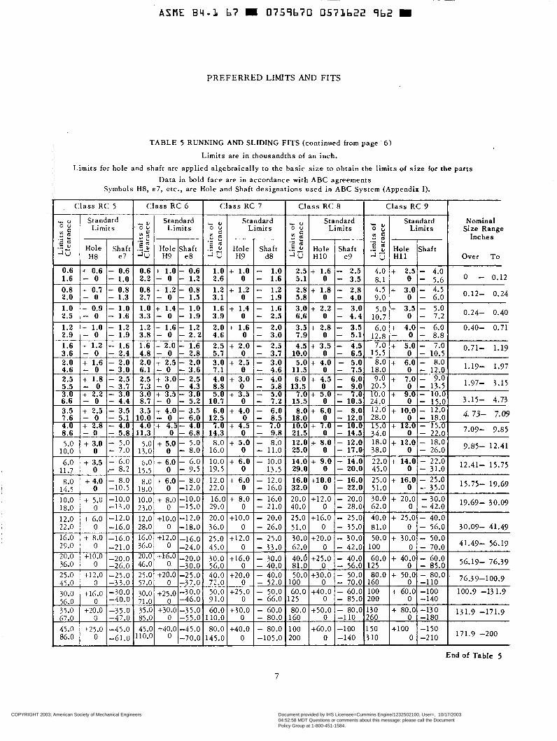
T A B L E 5 RUNNING AND SLIDING FITS (cont inued from page 6)
Limits are in thousandths of an inch. <
Limi ts for hole and shaf t are appl ied a lgebraical ly to the basic s ize to obta in the l imi t s of s i z e for t he pa r t s Data in bold face are in accordance with ABC agreements
Symbols Hg, e7, etc . , are Hole and Shaft designat ions used in ABC System (Appendix I).
C l a s s R C 9 C l a s s RC 5 C l a s s R C 6 C l a s s R C 7 C l a s s R C 8
'm Size Range Nominal
Inches
i ! 1 Hole H 1 1 IShaft Over To J- I I
4.0 I+ 2.51- 4.0 o - 0.12
0.12- 0.24
0.24- 0.40
0.40- 0.71
7.0 5.0 + 3.5 - 5.0
16.7 1- 1 /I l..: 12.8 8.8 6.0 + 4.0 -
I I I I I I I 1 I
- 1.2 1.2 + 1 . 6 - 1.2 2.0 + 1.6 - 2.0 3 . 5 + 2.8 - 3.5 - 1.9 3.8 - O - 2 . 2 4.6 O - 3.0 7.9 O - 5.1
7.0 + 5.0 - 7.0 0.71- 1-19
1::: + 6io 1 l!)i 1.19- 1.97
20.5 O - 13.5 1.97- 3.15 10.0 + 24.0 'O0 - 15.: 3.15- 4.73
- 10.
28.0 o - 18.0 12.0 + 10.0 - 12.0 4. 73- 7-09 15. + - 15*0
~~ -
15.5 O - 10.5
9.0 + 7.0 - 9.0
34.: l2O0 - 22.0 7.09- 9.85 18.0 + 12.0 - 18.0 38.0 O - 26.0 9.85- 12.41
- 1.6 1.6 + 2.0 - 1.6 2.5 + 2.0 - 2.5 4.5 + 3.5 - 4.3 - 2.4 4.8 - O - 2.8 5.7 O - 3.7 10.0 O - 6.3 - 2.0 2.0 + 2.5 - 2.0 3 .0 + 2.5 - 3.0 5.0 + 4.0 - 5.0 t - 3 .0 6.1 - O - 3.6 7.1 O - 4.6 11.5 O - 7.5 - 2.5 2.5 + 3 . 0 - 2 . 5 4.0 + 3.0 - 4.0 6 .0 + 4.5 - 6.a
- 3.0 3.0 + 3.5 - 3.0 5.0 + 3.5 - 5.0 7 .0 + 5.0 - 7.d - 4.4 8.7 - O - 5.2 10.7 O - 7.2 15.5 O - 10.5
- 3 . 7 7.3 - 0 - 4.3 8 .8 O - 5.8 13.5 O - 9.a t t t - 3.5 3.5 + 4 .0 - 3.5 6.0 + 4.0 - 6.0 8 . 0 + 6 .0 - 8.0
- 4. 4. + 4.5- 4 . . + 4.5 - - 5.; 11.; O - 6.; l i . ! O - 79.: 21.5 O - t::! 10.0 + 7.0 - - 5.1 10.0 - o - 6.0 12.5 o - 8.5 18.0 o - 12.0
- 5.0 5.0 + 5.0 - 5.0 8.0 + 5.0 - 8.0 12.0 + 8.0 - 12.0 - 7.0 13.n n - 8.0 16.0 O - 11.0 25.0 O - 17.E
t I
1;:: 1 + 3do 6.0 + 3.5
1 I 1 I l l
- 6.0 6.0 + 6.0 - 6.0 10.0 + 6 .0 - 10.0 14.0 + 9.0 - 14.C - 8.2 17.5 0 - 7.5 19.5 O 13.5 29.0 O - 20.C
-,.- -
- 8.0 -10.5 -10.0 -13 .O
-12.0 -16.0 -16.0 -21.0 -20.0 -26.0 "25.0 -33.0 -30.0 -40.0 -35.0
-
-
__
~
-
"47.0
16.0 +10.0 - 16.C 32.0 O - 22.C 20.0 +12.0 - 20.c 40.0 O - 28.C 25.0 t16.0 - 25.C 51.0 O - 35.C 30.0 +20.0 - 30.C 62.0 O - 42.C
81.0 O - 56.C 40.6 +25.0 - 40.C
100 O - 70.C 50.0 +30.0 - 50.C
60.0 +40.0 - 60.C 125 O - 85.c
~ 80.0 +50.0 - 8O.c 1160 o -110
30.0 + 20.0 - 30.0 19.69- 30.07 62.0 O - 42.0 40.0 + 25.0 - 40.0 81.0 O - 56.0 30.09- 41.49 - 26.0 22.0 I t :15.:1 1 - 33.0
30.0 +16.0 - 30.0 - 40.0 40.0 +20.0 - 40.0 72.0 - 52.0
25.0 +12.0 - 25.0 50.0 + 30.0 - 50.0 L O0 O - 70.0 4 1.49- 56.19
91.01 d 1 - 66.0 50.0 +25 O - -50.0
!O0 I O 1-140 I O0 + 60.0 -100 100.9 -131.9
60.0 +30.0 - 60.0 131.9 -171.9 67.0
-45.0 45.0 +40.0 -45.0 80.0 +40.0 - 80.0 100 +60.0 -100 -61.0 11O.O o -70.0 145.0 O -105.0 200 I I o 1-140
45.0 1-25.0 86.0 1 O
End of Table 5
7
COPYRIGHT 2003; American Society of Mechanical Engineers
Document provided by IHS Licensee=Cummins Engine/1232502100, User=, 10/17/200304:52:58 MDT Questions or comments about this message: please call the DocumentPolicy Group at 1-800-451-1584.
--``,````,````,``,`````,,````,,-`-`,,`,,`,`,,`---

www.bzfxw.com
USA STANDARD
TABLE 6 LOCATIONAL CLEARANCE FITS Limits are in thousandths of an inch.
Limits for hole and shaft are applied algebraically to the basic size to obtain the limits of size for the parts. Data in bold face are in accordance with ABC agreements.
Symbols H6, h5, etc., are Hole and Shaft designations used in ABC System (Appendix I).
~~
Class LC 5 Class LC 4 Class LC 1 Class LC 2 Class LC 3 Nominal
Size Range Inches
Over To
R 2 I Standard % $ Standard Limits
2.61- 6 I O + 1 6 + 0 0.K + 0.4 - 0.1 1
0.751 - O I- 0.35 O + 0.25 + O O + 0.4 + O
O +0.3 + o O +0.5 + O 0.5 - O -0.2 0.8 - O - 0.3 O +0.4 + O O +0.6 + O 0.65 - O -0.25 1.0 - O - 0.4 O +0.4 + O O +O.? + 0 0.7 - O -0.3 1.1 - O - 0.4
0 - 0.12 0.45 - O -0.2 0.65 - O "0.25 1 - 0 O + 0.6 O + 0.7 1.2 - o o + 0.9 1.5 - O o + 1.0 1.7 - O o + 1.2
2 - 0 O + 1.6 2.6 - O 3 - 0 O + 1.8
o + 2.2 3.6 - O O + 2.5
O + 2.8
O + 3.0
4.1 - 'O
4.6 - O 5 - 0
+ o - 0.5 t o - 0.6
- - 0.15 - 0.45 - 0.2 - 0.6
t o - 0.7 t o - 0.8 -
- 0.25 - 0.65 - 0.3 - 0.8
I O + 0 . 5 + O O +0.8 + O 0.9 - 0 -0.4 1.3 - O - 0.5 'm7'-
t o - 1 t o - 1.2 __
- 0.4 - 1.0 - 0.4 - 1.1
t o - 1.4 + o - 1.6 -
- 0.5 - 1.4 - 0.6 - 1.6
3*15- 4'73 1.5 - O -0.6 2.3 - O - 0.9 o +0.9 + O O +1.4 + O
1.7 - O -0.7 2.6 - O - 1.0 O +1.0 + O O +1.6 + O 4.73- 7*09 I I I I I I
O +1.2 + O O +1.8 + O 7.09- 9*85 2.0 - O -0.8 3.0 - O - 1.2
t o - 1.8
- 0.6 - 1.8 - 0.7 - 1.9 - 0.7 - 2.1
o +1.2 + o o + 2 . 0 + o 9*85" 12'41 I 2.1 I - O 1-0.9 I 3.2 I - O I - 1.2
+ o - 2.0 + O - 2.2
- 7- o + 3.5 5.7 - o 12-41-. 15-75 2.4 - 0 -1.0 3.6 - 0 - 1.4
O +1.4 + O O + 2 . 2 + O
2.6 - O -1.0 4.1 - O - 1.6 O +1.6 + O O + 2 . 5 + O 15-75- 19-69 + o - 2.5 o + 4 6.5 - O o + S 8 - 0 O + 6
10 - o O + E
13 - O o +10
16 - O o +12
20 - o O +16
26 - O o +20
32 - O O +25
41 - O
- 0.8 - 2.4 - 0.9 - 2.9
I I - 1 I I
+ O O +12.0 + O 0.9 + 3.0 - 3 20 - 0 "8 5 . 9 - 0
- 1.0 - 3.5 - 1.2 - 4.2 4 1.49- 56.19
- 1.2 - 5.2 - 1.4 - 6.4 - 1.6. - 7.6 - 1.8 - 9.8
O + 8.0 + O O +12 + O
16.0 - O -6.0 3 6 - O -10 O +10.0 + O O +16 + O
l3l .9 - 171.9 13 .O - 0 -5.0 20 - 0 - 8
- *Oo - 1.8 -11.8
Continued on page 9 8
COPYRIGHT 2003; American Society of Mechanical Engineers
Document provided by IHS Licensee=Cummins Engine/1232502100, User=, 10/17/200304:52:58 MDT Questions or comments about this message: please call the DocumentPolicy Group at 1-800-451-1584.
--``,````,````,``,`````,,````,,-`-`,,`,,`,`,,`---
标准分享网 www.bzfxw.com 免费下载
www.bzfxw.com
~~~~~
ASME B4.L 67 m 0759670 O573624 735 m
PREFERRED LIMITS AND FITS
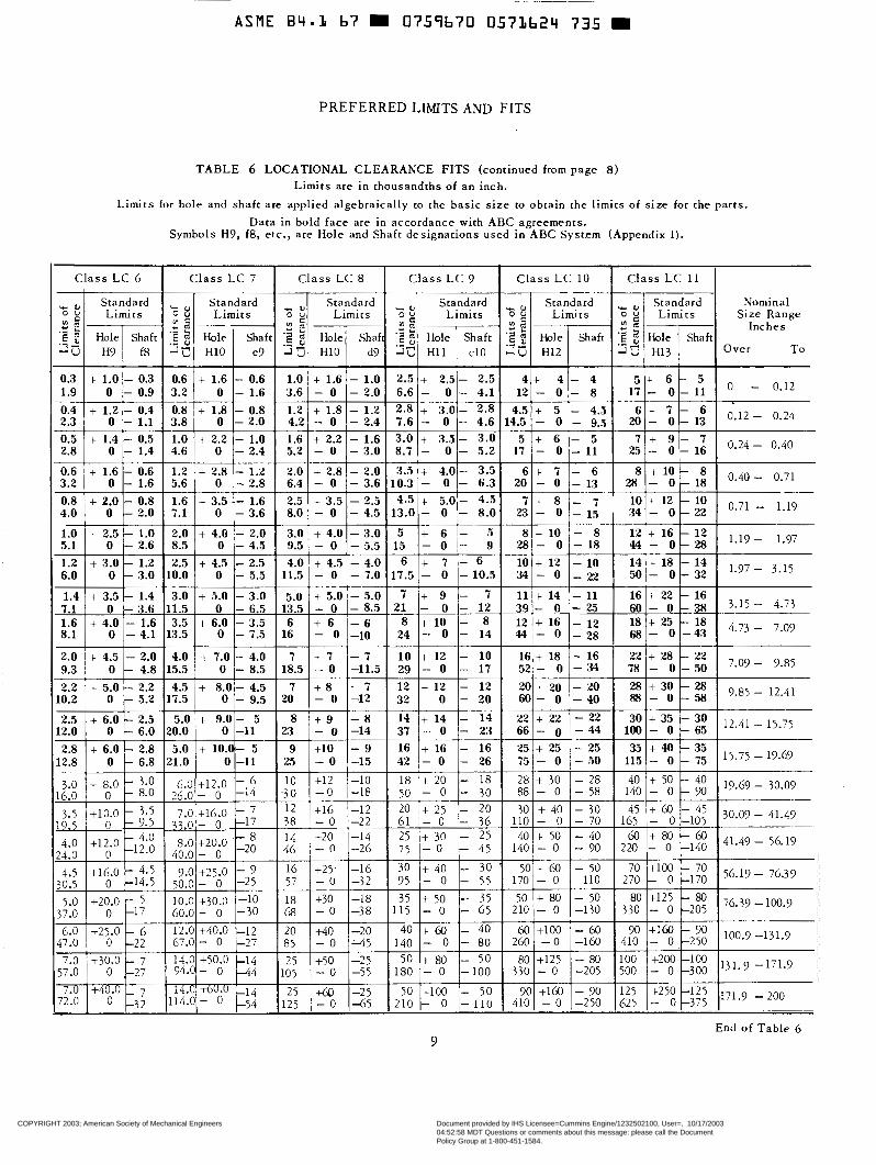
T A B L E 6 LOCATIONAL CLEARANCE FITS (cont inued from page 8 ) Limits are in thousandths of an inch.
L imi t s for hole and shaf t are appl ied a lgebraical ly to t h e b a s i c s i z e to obtain the l imits of s ize for the par ts . Da ta i n bold face are in accordance with ABC agreements .
Symbols H9, f8, etc., a re Hole and Shaf t des igna t ions used in ABC Systrm (Appendix I) .
C l a s s L C 6 Class L C 11 C l a s s LC 10 C l a s s L C 9 C l a s s L C 8 C l a s s L C 7
c e,
.- 2
m = Size Range Limits O 2 Limlts 2 Limits ; z Limits O U Limi t s 5 E Limits 0 U
Standard Standard Nominal Standard LI Stand.ard y. Standard c ~
Standard c
.g 9 2 : S 9 Hole Shaft Hole .e $ Shaft Hole 'B 2 Shaft Hole '2 5 Shaft Hole 'B 5 Shaft Hole :E 2 Shaft
- 2 Inches 2 s
H7 O v e r To H13 2s H12 ZÜ c10 H11 26 d9 H10 -IZ e7 H10 a z f8 .-
0.3
0.71 - 1.19 x i! ' l2 lo - O 34 - 1 5 - O 23 - 8.0 O 1 3 . 0 - - 4 . 5 - 0 8.0 - 3 . 6 O 7.1 - 2 . 0 O 4.0
- O"' - 18 - O 28 - 13 - O 20 - 6.3 - O 10.3 - 3.6 - O 6.4 - 2.8 O 5.6 - 1.6 O 3.2
7 7 + 9 - - 16 - O 25 - 11 - O 17 - 5.2 - O 8.7 - 3.0 - O 5.2 - 2.4 O 4.6 - 1.4 O 2.8
- 5 + 6 5 3.0 + 3.5- 3.0 - 1.6 t- 2.2 1.6 - 1.0 + 2.2 1.0 1 . 4 - 0 . 5 + 0.5
- I 13 - O 20 - 9.5 - O 14.5 - 4.6 - O 7.6 - 2.4 - O 4.2 - 2.0 O 3.8 - 1.1 O 2.3 6 + 7 6 - 4.5 + 5 4.5 2.8 + 3 . 0 - 2.8 - 1.2 + 1.8 1.2 - 0.8 + 1.8 0.8 - 0.4 + 1.2 0.4
+ 4 I- 4 4 2.5 + 2.5- 2.5 - 1.0 + 1.6 1.0 - 0.6 + 1.6 0.6 0.3 + 1.0'- 1.9 0 - 1 1 1 7 - - 0 , - 8 12 4.1 - O - 6 . 6 - 2 . 0 - 0 3.6 - 1 . 6 O 3.2 - 0 . 9 O
5 + 0 - 0.12 6 -
0.6 8 + l o - 8 - 6 + 7 6 3.5 + 4.0- 3.5 - 2 . 0 + 2 . 8 2.0 - 1 . 2 + 2.8 1.2 1 . 6 - 0 . 6 +
0.8 - 7 + 8 7 4 .5 + 5.0- 4.5 - 2.5 + 3.5 2.5 .- 1.6 + 3.5 1.6 - 0.8 + 2.0
5.1 - 14 + 18 14 - IO + 12 10 - 6 + 7 6 - 4.0 + 4.5 4.0 - 2.5 + 4.5 2.5 - 1.2 + 3.0 1.2
- - 28 - O 44 - 18 - O 28 - 9 - O 15 - 5.5 - O 9.5 - 4.5 O 8.5 - 2.6 O
1.0 1 2 + 1 6 - 1 2 - 8 8 t 1 0 - 5 + 6 5 + 4 . 0 - 3 . 0 3.0 + 4 . 0 - 2 . 0 2.0 + 2 . 5 - 1 . 0
6.0
3-15 - 4.73 - 38 - O 60 - O - 25 39 - 12 - O 21 - 8.5 - O 13.5 - 6.5 O 11.5 - 3.6 O 7.1
l.'" 3'15 - 32 - O 50 - 22 - O 34 - 10.5 - O 17.5 - 7.0 - O 11.5 - 5.5 O 10.0 - 3.0 O I
1.4 - 16 + 22 16 - 11 + 14 11 - 7 + 9 7 - 5.0 + 5.0 5.0 - 3.0 + 5.0 3.0 - 1.4 + 3.5
1.6
- 22 + 28 22 - 16 + 18 16 - 10 + 12 10 - 7 + 7 7 - 4.0 i~ 7.0 4.0 - 2.0 + 4.5 2.0
- 4 3 - O 68 - 28 - O 44 - 14 - O 24 -10 - O 16 - 7.5 O 13.5 - 4.1 O 8.1 4.73 - 7-03 - 18 + 25 18 - 12 + 16 12 - 8 + 10 8 - 6 + 6 6 - 3.5 + 6.0 3.5 - 1.6 + 4.0
9.3 "O7 - 9.85 - 50 - O 78 - 34 - O 52 - 17 - O 29 -11.5 - O 18.5 - 8.5 O 15.5 - 4.8 O
2.2 - 28 + 30 28 - 20 + 20 20 - 12 + 12 12 - 7 + 8 7 4.5 + 8.0- 4.5 - 2.2 + 5.0 10.2 - 40 - O 60 - 20 - O 32 "12 - O 20 - 9.5 O 17.5 - 5.2 O 88 3.85 - 12.41 58 - 0
2.5 12.41 - 15.75 - "," ~ 3 : lg - 22 + 22 22 - 14 + 14 14 - 8 + 9 8 5 + 9.0- 5.0 - 2.5 + 6.0
15.75 - 19.69 I ;! + * 35 12.0
- 25 + 25 25 - 16 + 16 16 - 9 +10 9 5 + 10.0- 5.0 - 2.8 + 6.0 2.8
- 44 - 0 66 - 23 - O 37 -14 - O 23 -11 O 20.0 - 6.0 O -
12.8 - O 115 - 50 - O 75 - 26 - O 42 -15 - O 25 -11 O 21.0 - 6.8 O
3.0 13.69- 30.09 - $ + 50 40 - 28 + 30 28 - 18 + 20 18 -10 +12 10 - 6 +12.0 6.0 - 3.0 + 8.0 16.0 - 58 - O 88 - 30 - O 50 -18 - O -30 -14 - 0 26.0 - 8.0 0 140 - - 0
3.5 +16.0 7.0 - 3.5 +10.0 - 7 - 45 + @I 45 - 30 + 40 30 - 20 + 2 5 20 -12 +16 12 30.09- 41-47
9 End of T a b l e 6
COPYRIGHT 2003; American Society of Mechanical Engineers
Document provided by IHS Licensee=Cummins Engine/1232502100, User=, 10/17/200304:52:58 MDT Questions or comments about this message: please call the DocumentPolicy Group at 1-800-451-1584.
--``,````,````,``,`````,,````,,-`-`,,`,,`,`,,`---

www.bzfxw.com
TABL
E 7
LOCA
TIO
NAL
TRAN
SITI
ON
FITS
Limits
ate
in
thous
andth
s of
an
inc
h.
Limits
fo
r ho
le an
d sh
aft
ate
applie
d alg
ebra
ically
to
the
basic
siz
e to
ob
tain
the
limits
of
siz
e fo
r the
m
ating
pa
rts.
Data
in bo
ld fac
e are
in
acco
rdanc
e wi
th
ABC
agre
emen
ts.
“Fit
,) re
pres
ents
the
max
imum
int
erfer
ence
(m
inus
value
s) an
d the
m
axim
um
cleara
nce
(plus
va
lues).
Sym
bols
H7,
js6,
etc.,
ate
Ho
le an
d Sh
aft
desig
natio
ns
used
in
ABC
Syste
m
(App
endix
I).
Nom
inal
Size
Rang
e Inc
hes
over
TC
0 -
0.12
0.12
- 0.2
4
0.24
- 0.4
0
0.40
- 0.7
1
0.71
- 1.1
9
1.19
- 1.9
7
1.97
- 3.1
5
3.15
- 4.7
3
4.73
- 7.0
9
7.09
- 9.8
5
9.85
- 12
.41
12.41
-
15.75
15.75
-
19.69
Clas
s LT
1
I Cl
ass
LT
2
I 3:
: +l
e2
-0
+0.3
-0
.3 +2
.4
-0.6
+1.8
-
0 +0
.6
-0.6
I I
I I
I -0
.4 1+
1.4
1 +0
.4
l-0.7
1+2.2
1
+0.7
I I
I I
I
a.6
1 +2
.0
1 +0
.6
I-l.0
1 +
3.0
1 +l
.O
- , , -
Clas
s LT
3
Stan
dard
Limits
Fi
t
fble
Shaft
H7
k6
-0.5
+0.6
+0
.5
to.5
-0
+O
.l
AI.5
+0
.7
+ 0.5
to
.6
-0
+O.l
-0.6
+0.8
+0
.6
to.7
-0
+O
.l
-0.7
+l.O
+0
.7
+0.9
-0
+O
.l
-0.8
+1
.2
+0.8
tl.1
-0
+O
.l
-1.0
+1
.4
+l.O
t1
.3
-0
+.O
.l
-1.1
+1.6
t1
.1
t1.5
-0
+O
.l
-1.4
+1
.8
+1.4
t1
.6
-0
+0.2
-1.4
+2.0
t1
.4
t1.8
-0
fO
.2
-1.6
+2.2
+
1.6
t2.0
-0
+0
.2
z.8
t2.5
+
1.8
t2.3
-0
+o
.z
Clas
s LT
4
Clas
s LT
5
-2.7
.+4.
0 t2
.7
-3,4
+2.5
+3
.4
-3.8
-0
to.2
f0
.7
-0
+1.8
Clas
s LT
6
-1.7
f1.0
+1
.7
w +0.3
-0
+0
.7
-2.0
t1.2
+2
.0
to.4
-
0 +
0.8
I
-2.4
+1.4
1+2/
i-
+0.4
:-i
-1 +
I.0
-
-2.8
~1
61
+2.8
to
.4
- -i-
I +I
.2
Y ,
-2
3
1'
QI +
3.2
Xii
Gi”L
6”1+
1.4
;‘,::
End
of
Table
7
CO
PY
RIG
HT
200
3; A
mer
ican
Soc
iety
of M
echa
nica
l Eng
inee
rs
D
ocum
ent p
rovi
ded
by IH
S L
icen
see=
Cum
min
s E
ngin
e/12
3250
2100
, Use
r=,
10/1
7/20
0304
:52:
58 M
DT
Que
stio
ns o
r co
mm
ents
abo
ut th
is m
essa
ge: p
leas
e ca
ll th
e D
ocum
ent
Pol
icy
Gro
up a
t 1-8
00-4
51-1
584.
--``,````,````,``,`````,,````,,-`-`,,`,,`,`,,`---
标准分享网 www.bzfxw.com 免费下载

www.bzfxw.com
ASME B4.L b7 m 0759b70 0573626 508
PREFERRED LIMITS AND FITS
TABLE 8 LOCATIONAL INTERFERENCE FITS Limits are in thousandths of an inch.
Limits for hole and shaft are applied algebraically to the basic size to obtain the limits of s ize for the parts.
Data in bold face are in accordance with ABC agreements,
used in ARC System (Appendix I). Symbols H7, p6, etc., are Hole and Shaft designations
0.24 - 0.40
100.9 -13 1.9 + 6.0
+30 - O 38 +16 - O 24 - 0 +38 +12 18 +24 +12 4 + 8.0 +25 - O 3 1 +12 - O 18 - 0 +31 +10 1 5 +18 +10 2
4 +16 +30 24 +16 +50 - 0 +40 - O 50 +ZO - O 30
131.9 -171.9
171.9 -200 +10.0
11 End of Table 8
COPYRIGHT 2003; American Society of Mechanical Engineers
Document provided by IHS Licensee=Cummins Engine/1232502100, User=, 10/17/200304:52:58 MDT Questions or comments about this message: please call the DocumentPolicy Group at 1-800-451-1584.
--``,````,````,``,`````,,````,,-`-`,,`,,`,`,,`---

www.bzfxw.com
USA STANDARD
Continued from page 5
f L N Z L N J
2 0 m - 3 HOL ES =WAFTS-
-2 SCALE: THMISANOTHS OF AN INCH - FOR A DIAMETER OF ONE INCH
FIG. 4 GRAPHICAL REPRESENTATION OF STANDARD LOCATIONAL INTERFERENCE FITS (SHOWN IN T A B L E 8)
LN Locational interference fits are used where accuracy of location is of prime importance and for parts requiring rigidity and align- ment with no special requirements for bore pressure. Such fits are not intended for parts designed to transmit fr ictional loads from one part to another by virtue of the t igh tness of fit, a,s these condi t ions are covered by force fits.
8.3.3 Force Fits. Force or shrink fits con- s t i tute a special type of interference fit, normal- ly characterized by maintenance of constant bore pressures throughout the range of s i z e s . T h e interference therefore varies almost directly with diameter, and the difference between its minimum and maximum value is small to maintain the re- sul t ing pressures within reasonable ‘ l imits .
T h e s e f i t s may be described briefly a s follows: FN 1 Light drive fits are those requir ing l ight
assembly pressures and produce more or less permanent assemblies. They are suit- able for thin sections or long fits, or in cast-iron external members.
FN 2 Medium drive fits are suitable for ordinary s t e e l p a r t s or for shrink fits on light sec- tions. They are about the t ightest fits that can be used with high-grade cast-iron ex- ternal members.
FN 3 Heavy drive fits are sui table for heavier steel pa r t s or for shrink fits in medium sec t ions . Force f i t s are suitable for parts which can
pressing forces required are be highly stressed or for shrink fits where
FNS 3
FN2 FN3 FN4 I
W 2”-FNI T I $ 0
FIG. 5 GRAPHICAL REPRESENTATION OF STANDARD FORCE OR SHRINK FITS (SHOWN IN TABLE 9 )
9. Modified Standard Fits
9.1 Bilateral hole or basic shaft system fi ts having the same amounts of c learance or inter- ference remain the same as those shown in Tables 5 to 9 , but the l imits of s ize a re ca lcu la ted for ho les or shaf ts and differ from those shown in the t ab le s . Th i s may be accomplished by one of the following:
(a) Bi la teral holes (Symbol B)-This will re-
(b) A basic shaft system (Symbol S)-This will s u l t in nonstandard holes and shaf ts .
result in nonstandard holes and shafts.
9.2 Bilateral Hole Fits (Symbol B). The com- mon c a s e is where holes are produced with fixed tools , such as drills or reamers; to provide a longer wear life for such tools a bilateral toler- ance is desired.
The symbols used for these f i ts are ident ical with standard f i ts except that they are followed by the le t ter “B.” Thus “LC4B”is a locat ional c learance f i t , c lass 4 , except tha t i s i s p roduced with a bilateral hole.
The l imits of c learance or interference are iden- t ical wi th those shown in Tables 5 to 3 for the corresponding fits.
The hole tolerance is changed so that the plus limit is that for one grade f iner than the value shown in the tables, the minus limit equals the amount by which the plus limit was lowered, and the shaft limits are both lowered by the same amount as the lower l imit of s i z e of the hole. The finer grade of tolerance can be found in Table 4.
9.3 Basic Shaft Fi ts (Symbol S). For these f i t s the maximum s i z e of the shaf t i s basic and the a l lowance i s appl ied to the ho le . The l imiv o f c learance or interference are identical with”@se shown in Tables. 5 to 3 for the corresponding fits. The symbols used for these f i ts are identi- cal with those used for standard fits except that they are followed by the letrer “S.” Thus “LC 4s” is a locat ional c learance f i t , c lass 4, ex- cept that it is produced on a basic shaf t basis .
The limits for hole and shaf t as given in Tables 5 to 9 are increased for clearance f i ts , or de- c reased for transit ion or interference f i ts , by the value of the upper shaft l imit; that is , by the amount required to change the maximum shaft to the basic s ize .
12
COPYRIGHT 2003; American Society of Mechanical Engineers
Document provided by IHS Licensee=Cummins Engine/1232502100, User=, 10/17/200304:52:58 MDT Questions or comments about this message: please call the DocumentPolicy Group at 1-800-451-1584.
--``,````,````,``,`````,,````,,-`-`,,`,,`,`,,`---
标准分享网 www.bzfxw.com 免费下载

www.bzfxw.com
~~ ~~
ASME 84.1 67 0759670 0573628 380
P R E F E R R E D LIMITS AND FITS
9.4 If s tandard s tock s izes or special condi t ions requi re th? use o f o ther ho le s izes and shaf t sizes, reference should be made for the required fi t to tables in Appendix I which are taken froh the ABC proposal.
10. Machining Processes .
To indicate the machining processes which may normally be expected to produce work within the tolerances indicated by the grades given in this Standard, Fig. 6 has been provided. This in- formation is intended merely as a guide in select- ing su i tab le p rocesses for a particular grade.
LAPPING a HONING
CYLINDRICAL GRlNOlN
SURFACE GRINDING
DIAMOND TURNING
DIAMOND BORING
BROACHING
REAMING
TURNING
BORING
MILLING
PLANING B SHAPINC
DRILLING
FIG . 6 D MACHINING PROCESSES
13
COPYRIGHT 2003; American Society of Mechanical Engineers
Document provided by IHS Licensee=Cummins Engine/1232502100, User=, 10/17/200304:52:58 MDT Questions or comments about this message: please call the DocumentPolicy Group at 1-800-451-1584.
--``,````,````,``,`````,,````,,-`-`,,`,,`,`,,`---
www.bzfxw.com
USA STANDARD
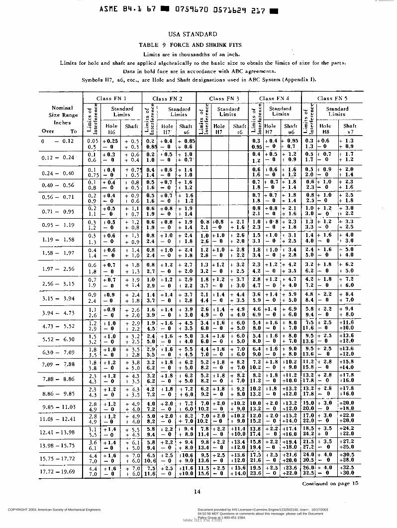
TABLE 9 FORCE AND SHRINK FITS
Limits are in thousandths of an inch.
Limi ts for ho le and shaf t a re appl ied a lgebra ica l ly to the bas ic s ize to obtain the l imits of s i z e for the parts. Data in bo ld face a re in accordance wi th ABC agreements.
Symbols H 7 , s6, etc . , are l lole and Shaft designat ions used in ABC System (Appendix I).
I C l a s s FN 1 C l a s s FN 4 I C l a s s FN 5 C l a s s FN 2 I C l a s s FN 3
Inches
Over To
O - 0.12 I 0.05
0.12 - 0.24.
0.1
1.97 - 2.56 I 2.56 - 3.15 I
3.94 - 4.73 2.6 1.1
2.9 1.2
3.2 1.5
3:5 1 8
4.73 - 5.52
5.52 - 6.30
6.30 - 7.09
7.09 - 7.88 3.8 2.3
2.3
7.88 - 8.86 4.3
8.86 - 9.85 4.3
15.75 - 17.72 7.0 4.4
Continued on page 15
14
COPYRIGHT 2003; American Society of Mechanical Engineers
Document provided by IHS Licensee=Cummins Engine/1232502100, User=, 10/17/200304:52:58 MDT Questions or comments about this message: please call the DocumentPolicy Group at 1-800-451-1584.
--``,````,````,``,`````,,````,,-`-`,,`,,`,`,,`---
标准分享网 www.bzfxw.com 免费下载
www.bzfxw.com
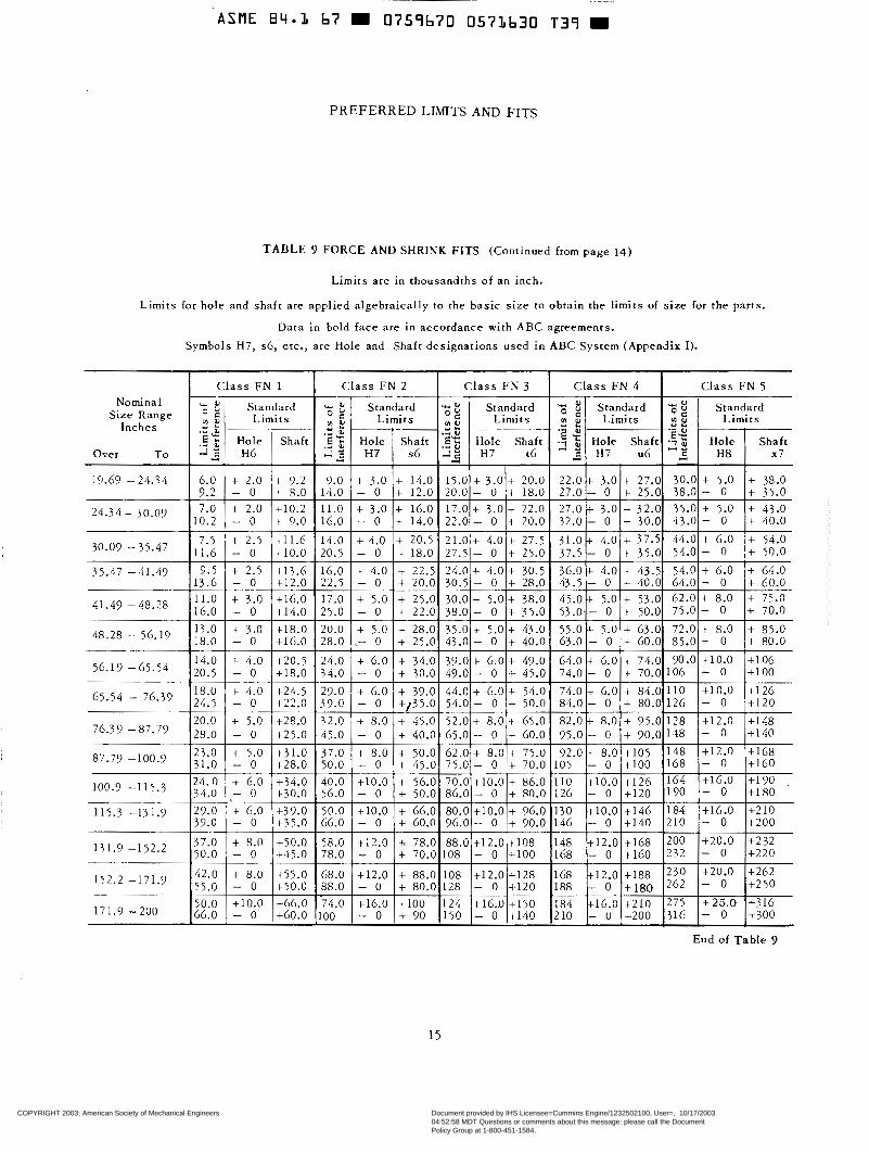
PREFERRED LIMITS AND FITS
T A B L E 9 FORCE AND SHRINK FITS (Continued from page 14)
Limi ts a re in thousandths of an inch.
Limits for ho le and shaf t a re appl ied a lgebra ica l ly to the bas i c s i ze t o ob ta in t he l imi t s of size for the parts.
Data in bold face are in accordance with ABC agreements .
Symbols H7, s 6 , etc. , are Hole and Shaft designations used in ABC System (Appendix 1).
Nominal S ize Range
Inches
Over To
19.69 - 24.34
24.34 - 30.09
30.09 - 35.47
35.47 -41.49,
41.49 -48.28
48.28 - 56.19
56.19 -65.54
65.54 - 76.39
76.3 9 - 87.79
87.79 -100.9
100.9 -1 15 .3
1 1 5 . 3 -13 1.9
131.9 - 1 5 2 . 2
152.2 -171.9
171.3 -200
C l a s s F N 1 C l a s s FN 2 C l a s s FN 3 C l a s s F N 4 Class FN 5 Standard al Standard - u Standard Standard 'i; Standard c r u
o g $ Limi t s z : Limits g Limits 2 2 Limi t s
2 3 H6 2 2 H7 s6 H7 c6 H 7 u 6 9 H 8 x7
6.0 + 2.0 + 9.2 9.0 + 3.0 + 14.0 15.0 + 3.0 + 20.0 22.0 + 3.0 + 27.0 30.0 + 5.0 + 38.0
7.0 t 2.0 +10.2 11.0 + 3.0 + 16.0 17.0 + 3.0 + 22.0 27.0 + 3.0 + 32.0 35.0 + 5.0 + 43.0 10.2 - O + 9.0 16.0 - O + 14.0 22.0 - O + 20.0 32.0 - O + 30.0 43.0 - O + 40.0
7.5 + 2.5 t l l . 6 14.0 + 4.0 + 20.5 21.0 + 4.0 t 27.5 31.0 + 4.0 + 37.5 44.0 + 6.0 + 54.0 11.6 - O +10.0 20.5 - O + 18.0 27.5 - O + 25.0 37.5 - O + 35.0 54.0 - O + 50.0
9.5 + 2.5 +13.6 16.0 + 4.0 + 22.5 24.0 t 4.0 + 30.5 36.0 + 4.0 + 43.5 54.0 + 6.0 + 64.0
11.0 + 3.0 + l G . O 17.0 + 5.0 + 25.0 30.0 + 5.0+ 38.0 45.0- t 5.0 + 53.0 62.0 + 8.0 + 75.0 16.0 - O +14.0 25.0 - O + 22.0 38.0 - O + 35.0 53.08.- O + 50.0 75.0 - O + 70.0 13.0 + 3.0 +18.0 20.0 + 5.0 + 28.0 35.0 + 5.0 + 43.0 55.0 + 5.0 + 63.0 72.0 + 8.0 + 85.0
14.0 t 4.0 +20.5 24.0 + 6.0 + 34.0 39.0 t 6.0 t 49.0 64.0 + 6.0 t 74.0 90.0 +10.0 + l o 6
18.0 + 4.0 +2/r.5 29.0 t 6.0 + 39.0 44.0 + 6.0 + 54.0 74 .0+ 6.0 + 84.0 110 +10.0 +126
20.0 + 5.0 +28.0 32.0 + 8.0 + 45.0 52.0 + 8.0 + 65.0 82.0 + 8.0 + 95.0 128 +12.0 +148
:E! Limits 2 2 O '
Ëa ._ 9 Hole Shaft E 2 Hole ' Shaft :$$ Hole Shaft Hole Shaft :$ Hole ' Shaft ds
' .* al Y & __
9.2 - O + 8.0 14.0 - O + 12.0 20.0 - O + 18.0 27.0 - O + 25.0 38.0 - O + 35.0
13.6 - O +12.0 22.5 - O + 20.0 30.5 - O + 28.0 43.5 - O + 40.0 64.0 - O + 60.0
18.0 - O +16.0 28.0 I- O + 25.0 43.0 - O + 40.0 63.0 - O + 60.0 85.0 - O + 80.0
20.5 - O +18.0 34.0 - O + 30.0 49.0 - O -t 45.0 74.0 - O t 70.0 106 - O + l o 0
24.5 - O +22.0 39.0 - O +/35.0 54.0 - O + 50.0 84.0 - O + 80.0 126 - O +120
End of T a b l e 9
15
COPYRIGHT 2003; American Society of Mechanical Engineers
Document provided by IHS Licensee=Cummins Engine/1232502100, User=, 10/17/200304:52:58 MDT Questions or comments about this message: please call the DocumentPolicy Group at 1-800-451-1584.
--``,````,````,``,`````,,````,,-`-`,,`,,`,`,,`---

www.bzfxw.com
ASME 84.1 b7 0759670 057Lb31 975
A P P E N D I X I
COPYRIGHT 2003; American Society of Mechanical Engineers
Document provided by IHS Licensee=Cummins Engine/1232502100, User=, 10/17/200304:52:58 MDT Questions or comments about this message: please call the DocumentPolicy Group at 1-800-451-1584.
--``,````,````,``,`````,,````,,-`-`,,`,,`,`,,`---
标准分享网 www.bzfxw.com 免费下载

www.bzfxw.com
ASME 84.3 67 m 0759670 0573632 BO3 W
APPENDIX I
N
- P
-
R
U
-
V
Limits for Holes C to X (Continued from page 16)
Tolerance Unit 0.001 in.
U-Upper Limit L-Lower Limit
6
7
8
6
7
8
9-1 1
9 10 1 1
Y .- . M E
L- u+ - L- U- L- U-
~
L-
L- U- L-
u-
~
L- L-
- N
d -4
I
O
- o. 1 - 0.3 0.0 0.4 0.0 0.6 0.2 0.4 o. 1 0.5 o. 1 0.7
-
-
- 0.0 1.0 - 1.6 2.5 -
6
7 -
6
7
6
7
6
"I- L- 0.8 U- 0.5
i L- 0.E u- ... L- ... u- ... L- ... + U- 0.c L- O.$ + u- O.( L- 1.c
L- ... 7 L U- - ... *
L- 1.1
- 0.5 1.; -
COPYRIGHT 2003; American Society of Mechanical Engineers
Document provided by IHS Licensee=Cummins Engine/1232502100, User=, 10/17/200304:52:58 MDT Questions or comments about this message: please call the DocumentPolicy Group at 1-800-451-1584.
--``,````,````,``,`````,,````,,-`-`,,`,,`,`,,`---

www.bzfxw.com
Y W ld c m -
C
-
d
e
APPENDIX I
LIMITS FOR SHAFTS c to x Tolerance Unit 0.001 in.
U-Upper Limit L-Lower Limit
;:: I 7.0 I 8.0 I 9. O
10.0 11.5 13.0 11.5 12.0 14.0 15.0 14.0 15.0 17.0 19.0 19.0 119.0 I 22.0 I 25.0
4.4
4.8 I 1 6.0 1 1:; 0.6 0.7 0.7 0.8 1.2 1.4 1.4 1.6 1.7 1.8
3.5 I 4.0 I 4.5 I 5.0 6.0 I 6.0 I 7.0 I 8.0 6.0 I 6.0 [ 7.0 I 8.0
Continued on page 19
18
COPYRIGHT 2003; American Society of Mechanical Engineers
Document provided by IHS Licensee=Cummins Engine/1232502100, User=, 10/17/200304:52:58 MDT Questions or comments about this message: please call the DocumentPolicy Group at 1-800-451-1584.
--``,````,````,``,`````,,````,,-`-`,,`,,`,`,,`---
标准分享网 www.bzfxw.com 免费下载

www.bzfxw.com
APPENDIX I
LIMITS FOR SHAFTS c to x (cont inued from p a g e 181
Tolerance Unit 0.001 in.
U-Upper Limit L-Lower Limit
I I I Diameters Over: To (Inches)
End of Table 19
COPYRIGHT 2003; American Society of Mechanical Engineers
Document provided by IHS Licensee=Cummins Engine/1232502100, User=, 10/17/200304:52:58 MDT Questions or comments about this message: please call the DocumentPolicy Group at 1-800-451-1584.
--``,````,````,``,`````,,````,,-`-`,,`,,`,`,,`---

www.bzfxw.com
APPEND1 X I I LENGTH DIFFERENCES PER lNCH FROM STANDARD FOR TEMPERATURES 38 TO 98 F
Temper- t Coefficient of thermal expansion of material per degree F, X 10 ature
Deg F
6
1 2 3 4 5 10 15 20 25 30 Total change in length from standard, microinches per inch of length*
38 -30 39 -29 40 -28 41 -27 42 -26
43 -25 44 -2 4 45 -23 46 -22 47 -2 1
48 -20 49 -19 50 -18 51 52
-17 -16
53 -1 5
55 54
-13 -14
56 -12 57 -11 58 -10 59 60 - 8
- 9
61 - 7 62 - 6
63 - 5 64 65
- 4 - 3
66 - 2 67 - 1 68 O 69 1 70 2 71 3 72 4 73 5 74 6 75 7 76 8 77 9 78 10
79 11 80 12 81 13 82 14 83 15
84 16 85 '17 86 18 87 19 88 20 89 21
94 26 95 27 96 28 97 29 98 30
-60 -58 -56 -54 -52
-50 -48 -46 -44 -42
-40 -38 -36 -3 4 -3 2
-3 O -28 -26 -24 -22 -20 -18 -16 -14 -12
-10 - 8 - 6 - 4 - 2
O
2 4 6
10 8
12 14 16
20 18
22 24 26 28 30
32
36 34
38 40 42 44 46 48 50 52 54 56
60 58
-90 -8 7 -84 -8 1 -78
-75 -7 2 -69 -66 -63 -60 -57 -54 -5 1 -48
-45 -42 -3 9 -3 6 -33 -30 -27 -2 4 -2 1 -18
-15 -12 - 9 - 6 - 3
O 3 6 9
12 15
21 18
24 27 30
33 36 39 42 45
48 51 54
60 57
63 66 69 72 75 78 81 84
90 87
-120 -116 -1 12 -108 -104
-100 - 96 - 92 - 88 - 84
- 80 - 76 - 72 - 68 - 64
- 60 - 56 - 52 - 48 - 44 - 40 - 36 - 32 - 28 - 24
- 16 - 20
- 1 2 - 8 - 4
O 4 8
12 16 20
28 24
32 36 40 44 48 52 56 60
64 68 72 76 80 84 88 92
1 O0 96
104 1 O8 112 116 120
-1 50
-140 -145
-135 -130
-125 -120 -1 15 -1 10 -105
-100 - 95 - 90 - 85 - 80
- 75 - 70 - 65 - 60 - 55 - 50 - 45 - 40 - 35 - 30
- 25 - 20 - 15 - 10 - 5
O
5 10 15 20 25 30 35 40 45 50
60 55
65 70 75
80 85 90 95
100 105 110 115 120 125 130 135 1 40 145 150
-300 -290 -280 -270 -260
-250 -240 -230 -220 -210
-200 -190 -180 -1 70 -160
-150
-130 -140
- I l 0 -120
-100 - 90 - 80 - 70 - 60
-' 40 - 50
- 30 - 20 - 10 O
10 20 30 40 50 60
80 70
90 1 O0
110 120 13 O 140 150
160 170 180 190 200 210 220 230 240 2 50 260 270 280 290 300
-450 -43 5 -420 -405 -3 90
-360 -375
-345 -3 30 -315 -300 -285 -270 -255 -240
-225 -2 10 -195 -180 -165 -1 50 -135 -120 -105 - 90
- 75 - 60 - 45 - 30 - 15
O 15 30 45 60 75
105 90
120 135 150 165 180 195 210 225
240 255 270 285 300 3 15 33 O 345 3 60 375 3 90 405 420 43 5 450
-600 -580 -560 -540 -520
-500 -480 -460 -440 -420
-400 -3 80 -3 60 -3 40 -320
-300
-260 -280
-2 40 -2 20
-200 -180 -160 -140 -1 20
-100 - 80 - 60 - 40 - 20
O
40 20
60 80
100
140 120
180 160
200 2 20 240 260 280 3 O0
3 40 3 20
3 60 3 80 400 420
460 440
480 500 520 540 5 60 5 80 600
-750 -725
-675 -700
-650
-625 -600 -575 -550 -525
-500 -475 -450 -425 -400
-375 -350 -325 -300 -275 -250 -225 -200 -175 -1 50
-125 -100 - 70 - 50 - 25
O
25 50 75
1 O0 125 150 175 200 225 2 50
300 275
325 350 375
400 425 450 475 500 525 550
600 575
625 650 675 700 725 750
-900 -870 -840 -810 -780
-750 -720 -690 -660 -630
-600 -570 -540 -510 -480
-450 -420 -3 90 -360 -3 30 -300 -270 -240 -210 -180
-150 -120 - 90 - 60 - 30
0
30 60 90
120 150 180 210 240 270 300
3 60 330
3 90 420 450
480 510 540
600 570
63 O 660 690 720 750 780 810 840 8 70 900
For intermediate coefficients add appropriate listed values. For example, a length change for a coefficient of 7 i s the sum of values in the 5 and 2 columns. Fractional interpolation may be similarly calculated. *Or hundredths of micron (microns/100) per centimeter.
20
COPYRIGHT 2003; American Society of Mechanical Engineers
Document provided by IHS Licensee=Cummins Engine/1232502100, User=, 10/17/200304:52:58 MDT Questions or comments about this message: please call the DocumentPolicy Group at 1-800-451-1584.
--``,````,````,``,`````,,````,,-`-`,,`,,`,`,,`---
标准分享网 www.bzfxw.com 免费下载

www.bzfxw.com
APPENDIX II
LENGTH DIFFERENCES PER CENTIMETER FROM STANDARD TEMPERATURE O TO 40 CELSIUS
Temper- Coefficient of thermal expansion of material per degree C, x 10
Deg c Total change in length from standard, hundredths of microns (microns/lOO)per centimeter of length.
ature 1 2 3 4 5 10 15 20 25 30
O 1 2 3 4
5 6 7 8 9
10 11 12 13 14
15 16 17 18 19 20 21 22 23 24
26 25
27 28 29
30 31 3 2 33 34
36 35
37 38 39 40
-20 -40 -19 .-38 -18 -36 -17 -34 -16 -32 -15 -30 -14 -28 -13 -12 -24
-26
-11 -22
-10 -20 - 9 -18 - 8 -16 - 7 -14 - 6 -12
- 5 -10 - 4 - 8 - 3 - 6 - 2 - 4 - 1 - 2
O O 1 2
2 4
3 6 4 8
5 10 6 12 7 14 8 16 9 18
10 20 11 22 12 24
l3 28 26
14
l 5 32 30
16 17 34 18 36
20 l9 40 38
-60 -80 -57 -76 -54 -72 -5 1 -68 -48 -64
-45 -60 -42 -56 -39 -52 -36 -48 -33 -44
-30 -40 -27 -36 -24 -32 -21 -28 -18 -24
-15 -20 -12 -16 - 9 -12 - 6 - 8 - 3 - 4
O O 3 6
4 8
9 12
12 16
20 18 l 5 2 4 21 28 2 4 3 2 27 36
30 33
40 44
36 48 39 52 42 56
45 64 60
48 51 68 54 72 57 60
76 80
-100 - 95 - 90 - 85 - 80
- 75 - 70 - 65 - 60 - 55
- 50 - 45 - 40 - 3 5 - 30
- 25 - 20 - 15 - 10 - 5
O 5
10
20 15
30 25
40 35
45
50
60 55
65 70
75 80 85 90 95
1 O0
-200 -190 -180 -170 -160
-150 -140 -13 O -120 -1 10
-100 - 90 - 80 - 70 - 60
- 50 - 40 - 30 - 20 - 10
O 10 20 30 40
50 60 70 80 90
100 110 120 130 140
150 160 170 180
200 190
-3 O0 -285 -270 -255 -240 -22 5 -2 10 -195 -180 -165
-1 50 -13 5 -120 -105 - 90
- 75 - 60 - 45 - 30 - 15
15 O
30
60 45
75 90
105 120 13 5
150 165 180
210 195
225 240 255 2 70 285 300
-400 -3 80 -360 -3 40 -3 20 -3 O0 - 280 -2 60 -240 -220
-200 -180 -160 -140 -1 20
-1 O0 - 80 - 60 - 40 - 20
20 O
40 60 80
1 O0 120
160 140
180
200 220 2 40 2 60 280
300
3 40 320
3 60 380 400
-500 -475 -4 50 -425 -400
-3 75 -3 50 -325 -3 O0 -275
-250 -22 5 -200 -175 -150
-125 -100 - 75 - 50 - 25
O 25 50
100 75
125 150
200 175
225
250
3 O0 275
325 3 50
3 75 400 425 4 50 475 500
-600 -570 -540 -510 -480
-450 -420 -390 -360 -330
-3 O0 -270 -240 -2 10 -180
-1 50 -120 - 90 - 60 - 30
0 30 60 90
120
150 180 210 240 270
3 O0 330 3 60 3 90 420
450 480 510 5 40
600 570
For intermediate coefficients add appropriate listed values. For example, a length change for a coefficient of 11 is the sum of the values in the 10 and 1 columns. Fractional interpolations may be similarly calculated. *Or microinches per inch.
1C = 1.8 F
21
COPYRIGHT 2003; American Society of Mechanical Engineers
Document provided by IHS Licensee=Cummins Engine/1232502100, User=, 10/17/200304:52:58 MDT Questions or comments about this message: please call the DocumentPolicy Group at 1-800-451-1584.
--``,````,````,``,`````,,````,,-`-`,,`,,`,`,,`---