Manual Vsc
15
DOC. NO. : VP-MM-010A/0 MANUAL FOR VSC PUMP Instructions on Installations, Operation and Maintenance of Horizontal Two Stage Split Casing Centrifugal Pump Manufactured By : Varat Pump & Machinery Pvt. Ltd. 20, Netaji Subhas Road, Kolkata – 700001 West Bengal, INDIA Ph. No.: 033-2230 1903, 2243 4500 FAX No.: 033-2230 1535/6274 E-Mail : [email protected]
-
Upload
kaushik-chakraborty -
Category
Documents
-
view
244 -
download
1
Transcript of Manual Vsc

7/31/2019 Manual Vsc
http://slidepdf.com/reader/full/manual-vsc 1/15
DOC. NO. : VP-MM-010A/0
MANUAL FOR VSC PUMP
Instructions on Installations,
Operation and Maintenance of Horizontal Two Stage Split
Casing Centrifugal Pump
Manufactured By :
Varat Pump & Machinery Pvt. Ltd.20, Netaji Subhas Road, Kolkata – 700001
West Bengal, INDIA
Ph. No.: 033-2230 1903, 2243 4500
FAX No.: 033-2230 1535/6274
E-Mail : [email protected]

7/31/2019 Manual Vsc
http://slidepdf.com/reader/full/manual-vsc 2/15
Page 1 of 14
1.0 GENERAL
1.1 This book let covers instructions for following Models of VARAT Horizontal Centrifugal Axial Split
Casing Pump Model:
80VSC-76
100VSC-76
100VSC 16
1.2 When the pumps are received sometime before the use of the pump it should be located in dry place.
The coupling should be rotated once in a month to prevent pilling of bearing surfaces.
1.3 When the pumps kept idle for a period after one use, it should be cleaned properly and overhauling
should be made before long storage.
2.0 INSTALLATION
2.1 LOCATION
The pump should be located as near the liquid source as possible. This will minimize the suction lift
and pump will give better performance.
Ample space should be provided on all the sides so that the pump can be inspected while in operation
and can be serviced conveniently whenever required.
2.2 FOUNDATION
The foundation should be sufficiently substantial to absorb any vibration and to form a permanent
rigid support for the base plate. This is important in maintaining the alignment of a direct connected
unit. A concrete foundation on a solid base is advisable. Foundation bolts of the proper size should
be embedded in the concrete located by a drawing or template. A pipe sleeve about two and one-half
diameter larger than the bolt should be used to allow movement for the final position of thefoundation bolts.
2.3 ALIGNMENT
Pumps and drivers that are supplied by the manufacturers, mounted on a common base frame are
accurately aligned before despatch. All base frames are flexible to some extent and alignments are
likely to be disturbed during transit to some extent and therefore must not be relied upon to maintain
the factory alignment. Re-alignment is necessary after the complete unit has been leveled on the
foundation and again after the grout has set and foundation bolts have been tightened. The alignment
must be checked after the unit is piped up and re-checked periodically.
2.4 LEVELLING
When the unit is received with the pump and driver mounted on the base plate, it should be placed on
the foundation and the coupling halves disconnected. The coupling should not be reconnected until
all alignment operations have been completed. The base plate must be supported evenly and placed
closed to the foundation bolt. In each case, the supports should directly under the part base plate
carrying the greatest weight and spaced closely enough to give uniform support. A gap of about 25 to
50 mm should be allowed between the base plate and foundation of grouting. Supporting will be
such that it will not be distorted or sprung by the uneven distribution of the weight. Adjust the
wedges until the shafts of the pump and driver are in level. Check the coupling faces, suction and
discharge flanges for the horizontal or vertical position by means of spirit level.
7/31/2019 Manual Vsc
http://slidepdf.com/reader/full/manual-vsc 3/15
Page 2 of 14
2.5 FLEXIBLE COUPLING
A flexible coupling will not compensate for misalignment of the pump and driver shafts. The
purpose of the flexible coupling is to compensate for temperature changes and to permit the
movement of the shafts without interference with each other while transmitting power from the
driver to the pump.
2.6 MISALIGNMENT
There are two types of misalignment between the Pump shaft and the driver shaft:
(a) Angular misalignment: Shafts with axis concentric but not parallel.
(b) Parallel misalignment: Shafts with axis Parallel but not concentric.
The unit can then be grouted by soft concrete under the edges.
DIAL GAUGE ALIGNMENT
An approved method for putting the coupling halves in final accurate alignment is by the use of a
dial indicator. Check the alignment by straight edge and fillers as accurately as possible as described below. Fasten the indicator to the pump half of the coupling with the indicator button resting on the
other half of the coupling periphery (FIG 3). Set the dial to the 0 and chalk mark the coupling half
beside where the bottom rests. For any check, top or bottom or sides, rotate both shafts by the same
amount i.e. all readings on the dial must be made with bottom beside the chalk mark. The dials
reading will indicate whether the driver has to be raised or lowered or moved to either side.
Accurate alignment of shaft center can be obtained with this method.
7/31/2019 Manual Vsc
http://slidepdf.com/reader/full/manual-vsc 4/15
Page 3 of 14
2.7 GROUTING
When the alignment is correct, the foundation bolts should be tightened evenly but not too firmly.
Working soft concrete under the edges can then grout the unit. Foundation bolts should not be fully
tightened until the grout is hardened, usually 48 hours after pouring.
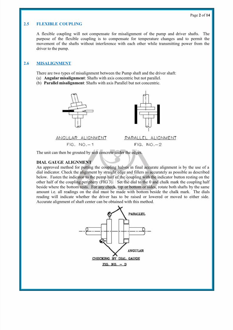
2.8 PIPING
Both suction and delivery pipes and accessories should be independently supported near the pump so
that when the flange bolts are tightened no strain will be transmitted to the pump casing. It is usually
advisable to increase the size of both suction and delivery pipes at the pump nozzles in order to
decrease the loss of head from friction and for the same reason piping should be arranged with as
minimum bends as possible, as these should be made with a long radius wherever possible. The pipe
lines should be free from scales, welding residuals etc., and have to be mounted in such way that
they can be connected to suction and delivery flanges without any stress on the pump. Adequate
supports should be given to pipe lines so that the weight of the pipelines does not fall on the pump.
The use of minimum number of the bends and other fittings will minimize the friction losses.
2.9 SUCTION PIPE
The suction pipe should be as short as possible. This can be achieved by placing the pump close to
the liquid to be pumped. The suction pipe must be kept free from air leaks. This is particularly
important when the suction lift is high. A horizontal suction line must have a gradual rise towards.
To the pump. Any high point in the pipe will be filled with air and thus prevent proper operative of the pump. A concentric taper piece should not be used in a horizontal suction line as it forms an air
pocket in the top of the reducer and the pipe. Use an eccentric per piece (FIG. NO.- 4).
The end of the suction pipe must be well submerged to avoid whirlpools and ingress of air but must
be kept clear of any deposits of mud, silt grit etc. The pipe must be clear from any side of wall by at
least 450mm. The end of the suction pipe should be provided with a strainer of sufficient open area.

7/31/2019 Manual Vsc
http://slidepdf.com/reader/full/manual-vsc 5/15
Page 4 of 14
2.10 DELIVERY PIPE
A check (non-return) valve and a gate or sluice valve-regulating valve) should be installed in the
discharge line. The check valve placed between the pump and the gate valve is to protect the pump
from excessive pressure and to prevent water running back through the pump in case of failure of the
driving machine i.e.-excessive backpressure.
Discharge piping should be provided with a sluice valve to control the discharge, if required. The
valve is used in primary, starting and when shutting down the pumps. If increases are used on thedischarge side to increase the size of discharge piping they should be placed between the check valve
and pump.
2.11 VACCUM EQUALIZING LINE (AND LIQUID LINE)
If the pump draws from system under vacuum a equalizing pipe must be carried from the highest
point of the suction line, however, as close to the suction flange of the pump as
Possible, to the top of the feed tank to keep gas bubbles that might have been entrapped in the flow
from entering the pump. The line should be fitted with an isolating valve, which should be closed
only for maintenance work on the pump set.
Apply sealing liquid (external sealing) to the shaft seal cage to prevent entry of air in the case of
pumps with packed stuffing box. It is convenient to tap the sealing liquid from the delivery line
above the non-return valve. Arrangement explained in FIG. NO.-5.
2.12 FOOT VALVE
It is advisable to install a foot valve to facilitate priming of pump. Foot valve should have sufficient
clear passage for water. Care must be taken to prevent foreign matter from being drawn into the
pump or choking the foot valve and for this purpose an efficient strainer should be provided.
2.13 STUFFING BOXES AND PACKING
Stuffing boxes should be carefully cleaned and the packing placed in them. Be sure that sufficient
packing is placed at the back of the water seal cage. If the water to be pumped is dirty or gritty,
sealing water should be piped to the stuffing boxes from clean outside source of supply in order to

7/31/2019 Manual Vsc
http://slidepdf.com/reader/full/manual-vsc 6/15
Page 5 of 14
prevent damage to the packing and shaft. In placing the packing, each packing ring should be cut to
the proper length so that ends come together but do not overlap. The succeeding rings of packing
should be placed in the Stuffing Box so that the joints of the several rings of packing are staggered
and cutting the shaft. If the stuffing box is not properly packed, friction in stuffing box prevents
turning the rotor by hand. On starting the pump, Stuffing Box Packing should be left slightly loose
without causing an air leak, and if it seems to leak instead of putting too much pressure on the gland,
put some heavy oil in the stuffing box until the pump works properly and then gradually tighten up
the gland. The packing should be occasionally changed.
MECHANICAL SEAL (APPLICABLE FOR BALANCE SEAL)
Since mechanical seals are made in a wide variety of designs, the instruction for the specific seal
must be carefully studied and followed exactly. A Mechanical Seal is a precision device and must be
treated accordingly. If any leakage is found, observe carefully whether it is found :-
1) Between shaft & sleeve or
2) Between stuffing box flange and sleeve or
3) Between stuffing box and seal cover
For clause no.1 ‘O’ ring between shaft and sleeve are to be replaced.
For clause no.2 if adequate leakage from the sleeve surface is found then after inspection of the seal
face damage, compression of the seal is to be increased. Unscrewing 4 nos. align screws for holding
rotary part on the sleeve, you have to slide the seal rotary part towards the stationary part and
tightening the 4 nos. align screw can do this. You have to keep the compression of the seal about 3 to
4 mm. If the leakage is little then it is normally through the `O’ Ring provided inside the rotary seal.
The ring may be required to be replaced. For clause no.3 tighten the 4 nos. gland nut (No. 29), if any
further leakage found then seal cover ‘O’ ring/gasket (No.21) is to be replaced.
2.14 LUBRICATION
Pump is usually provided with grease cap. Initially fill up grease at grease cap provided at bearing
bracket.
2.15 BALL BEARING
Correct maintenance of ball bearings is essential. The bearing manufacturers give the following as
guide to relubrication periods under normal conditions.
Quarterly when on continuous duty.
Half yearly when on eight-hour per day duty.
The bearings and housings should be completely cleaned and recharged with fresh oil after 2500
hours or the nearest pump overhaul time.
2.16 PRIMING
No pumping action occurs unless the pump casing is filled with liquid. Pump casing and suction pipe
must therefore be completely filled with the liquid and thus all air removed before the pump is
started. Several different priming methods can be used depending on the kind of installation and
service involved.
(1) Liquid level above pump level.
Pump is set below liquid level of source of supply so that liquid always flows to pump under
positive head.
(2) Priming with Foot Valve.

7/31/2019 Manual Vsc
http://slidepdf.com/reader/full/manual-vsc 7/15
Page 6 of 14
(a) When pump is installed on suction lift with foot valve at the end of suction line, fill
pump with water from some outside source till all air is expelled and water flows
through air vent.
(b) When there is liquid under some pressure in the discharge pipe, priming can be
effected by bypassing the pressure liquid around the check and gate valve. Of course,
the initial priming must be effected from some outside source.
NOTE: In this case, the foot valve must be capable of withstanding pump pressure and
possible surge.
(3) Priming by ejector: An ejector operated by steam, compressed air or water under pressure and
connected to air vent on top of casing can be used to remove air from and prime the pump on
suction lift installations.
(4) Priming by dry vacuum pump: A hand or power pump sucks in all the air from the casing and
the suction pipe, and thus primes the system
3.0 PREPARATION OF PUMP STARTING:
After the pump and the drive are mounted, the plant should be prepared for starting. The
following rules should be observed before starting the pump:
3.1 The pins are pad should be inserted into the coupling not before making sure of the correct
rotation of drive motor. In case of the drive rotating in the wrong direction, the connection of
two cable conductors supplying the current to the motor should be interchange in case of
DOL starting.
3.2 Check presence of oil in bearings and correct location of water deflector on shafts that ensure
flashing, quenching, lubrication in case of mechanical seal as well as if required as per
design.
3.3 Gland packing should be tightly stuffed, but not over tightened. The sealing packing should
be tightened to such an amount as to allow the pumping liquid to seek to the outside. Over
tightening of sealing packing causes quick wear out of shaft sleeves, increases its friction and
lowers the efficiency factor of the whole plant.
3.4 Check the free rotation of pump rotor, turning it by hand to verify any major obstruction or
friction with wearing parts.
3.5 Check the proper order of suction and pressure pipelines, tightening of flanges, fittings of
inlet valve and presence of drain plug, air cock for vent etc.
3.6 Check the correct direction of rotation of pump and drive. The pump rotor should rotateaccording to direction of rotation marked on pump.
3.7 Getting reasonably sure of the proper order of the whole plan and its readiness for operation,
the suction pipe should be primed with water / liquid. Arrangement for priming funnel and
three ways connection of pressure gauge with air-cock after delivery flange but before
delivery sluice valve is required.
3.8 The pump is being filled up (Primed) until the air-cock produces water jet without air
bubbles. Then the primary funnel, air-cock and sluice valve is required to be closed. After all
these operation and checking, the pump is ready for starting.

7/31/2019 Manual Vsc
http://slidepdf.com/reader/full/manual-vsc 8/15
Page 7 of 14
4.0 STARTING AND STOPPING OF THE PUMP:
4.1 The pump should be loaded gradually, when the drive is engaged. When the prime movers
attain full speed, the regulating sluice valve should be smoothly opened. This will avoid
overloading of the drive.
4.2 On the other hand it should be kept in mind that a lengthy operation with completely close
sliding valve is likewise to be avoided, since this causes unnecessary heating of the liquid inthe pump.
4.3 By controlling the sliding valve the required flow and head may be obtained. After setting of
pressure gauge at required point, check ampere consumption. If found value exceeds required
value, pump should be stopped
5.0 BEARINGS:
The pump is supplied with anti-friction ball bearings at DE and angular contact ball back to
back at NDE (2 nos. Bearing to be provided as per drawing, keeping open side of two bearings outward) and Lock by bearing nut with lock washer as applicable. One thrust collar
ring inserted between bearing and shaft edge.
Generally SKF/NBC/RHP equivalent bearings are used.
6.0 LUBRICANT:
Bearings are normally grease lubricated. Bearing temperature is permissible to rise 40 degree
Centigrade above ambient temperature. Lithium based wheel bearing grease must be used of
reputed brand.
7.0 STUFFING BOX:
Stuffing Boxes are extra deep and suitable for balance mechanical seal. Mechanical seal must
be over oiled before starting the pump after long time storage.
8.0 GASKET
Compressed asbestos packing gasket for joining of volute casing is used. However, packing
gasket suitable to handle corrosive liquid and high temperature fluid is supplied against
specific requirements.
9.0 COUPLING
Normally pin bush type flexible coupling is used. Other type of coupling may be supplied
against specific requirements.
10.0 GUIDE RING / WEARING RING
Replaceable throat bush as guide ring and ring to protect the both side of impeller provided at
casing in VSC type pumps.

7/31/2019 Manual Vsc
http://slidepdf.com/reader/full/manual-vsc 9/15
Page 8 of 14
11.0 SHAFT SLEEVES
Replaceable sleeve for protecting the shaft for gland packed pump and for balance seal, step
down sleeve is being provided.
12.0 SPARE PARTSOne set Anti-friction bearing, Wearing Ring, Shaft Sleeve, Gland Packing, Casing Gasket
must always be kept with the actual users of the pump to ensure uninterrupted service from
the pump.

7/31/2019 Manual Vsc
http://slidepdf.com/reader/full/manual-vsc 10/15
Page 9 of 14
13.0 TROUBLE SHOOTING
SL.
NO.DEFECTS CAUSES REMEDY
1. Pump does
not deliver
liquid.
(1)Insufficient quantity of
water/water not filled in
pump casing
(1) Fill up pump casing
with clear water or liquid
to be pumped.
(2) Incorrect direction of
rotation.
(2) Change the direction of
rotation of prime mover.
(3) Pump is clogged. (3) Check up Impeller may
clog. Clean Suction pipe
and Strainer.
(4) Pump speed too low. (4) Check up speed of
prime mover and adjust.
(5) Suc. Lift too high. (5) Reduce Suc. Lift.
(6) Leakage in Suc. Pipe. (6) Prevent leakage in suc.
Pipe.
(7) Incorrect layout of Suc.Line.
(7) Correctly install theSuc. Line.
(8)Valve in Suc. Line not
open properly.
(8) Check up the opening
of line valve.
(9) Shaft Sleeve & Gland
packing worn and air leaks.
(9) Replace Shaft-Sleeve
& Gland Packings.
(10) Delivery liquid too
viscous.
(10) Liquid viscosity to be
checked & corrected.
(11) Incorrect selection of
pump for operating
condition.
(11) Replace the pump
with a suitable designed
capacity.
2. Flow not
adequate.
(1) Speed too low. (1) Check up speed of
prime mover and adjust.
(2) Leakage in Suction side
fitting and piping
(2) Prevent leakage in
suction pipe and fittings.
(3) Discharge Head too high. (3) Check up vertical head
and frictional losses.
(4) Pump Casing empty. (4) Fill up the pump
casing.
(5) Rubber Flap Valve
clogged.
(5) Check up rubber Flap
assembly & leakage from
pump casing.(6) Shaft Sleeve/Gland
packing worn and air leaks.
(6) Replace the shaft
Sleeve/Gland Packing.
(7) More clearance between
Impeller and Wearing Plate.
(7) Measure the clearance
between Impeller and
Wearing Plate and adjust
by using proper Packing.
(8) Suction lift too high or
suction pipe too long.
(8) Avoid High Suction
lift and Suction piping.
7/31/2019 Manual Vsc
http://slidepdf.com/reader/full/manual-vsc 11/15
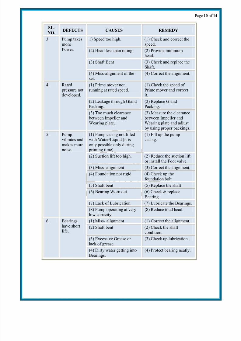
Page 10 of 14
SL.
NO.DEFECTS CAUSES REMEDY
3. Pump takes
more
Power.
1) Speed too high. (1) Check and correct the
speed.
(2) Head less than rating. (2) Provide minimum
head.
(3) Shaft Bent (3) Check and replace the
Shaft.
(4) Miss-alignment of the
set.
(4) Correct the alignment.
4. Rated
pressure not
developed.
(1) Prime mover not
running at rated speed.
(1) Check the speed of
Prime mover and correct
it.
(2) Leakage through Gland
Packing.
(2) Replace Gland
Packing.
(3) Too much clearance
between Impeller andWearing plate.
(3) Measure the clearance
between Impeller andWearing plate and adjust
by using proper packings.
5. Pump
vibrates and
makes more
noise.
(1) Pump casing not filled
with Water/Liquid (it is
only possible only during
priming time).
(1) Fill up the pump
casing.
(2) Suction lift too high. (2) Reduce the suction lift
or install the Foot valve.
(3) Miss- alignment (3) Correct the alignment.
(4) Foundation not rigid (4) Check up the
foundation bolt.(5) Shaft bent (5) Replace the shaft
(6) Bearing Worn out (6) Check & replace
Bearing.
(7) Lack of Lubrication (7) Lubricate the Bearings.
(8) Pump operating at very
low capacity.
(8) Reduce total head.
6. Bearings
have short
life.
(1) Miss- alignment (1) Correct the alignment.
(2) Shaft bent (2) Check the shaft
condition.
(3) Excessive Grease or lack of grease.
(3) Check up lubrication.
(4) Dirty water getting into
Bearings.
(4) Protect bearing neatly.

7/31/2019 Manual Vsc
http://slidepdf.com/reader/full/manual-vsc 12/15
Page 11 of 14
14.0 MAINTENANCE
Preventative maintenance schedule are the periodical checks and precautions by which possibilities
of failures and breakdowns are made very remote.
14.1 Daily Checks
1.1 Pressure gauge reading1.2 Bearing temperature
1.3 Leakage through stuffing box
1.4 Noise and vibration
1.5 Voltage and current
1.6 Constant flow of cooling water.
14.2 Periodical Maintenance
1.1 Replace the grease for bearing lubrication
1.2 Change the stuffing box packing.
1.3 Check the alignment of the pump set
1.4 Calibrate the measuring instruments
1.5 Check the sealing and cooling connections etc.
15.0 OVERHAULING
Normally the pump will be due for overhauling after about 3000 working hours. Pump dismantling
and assembling should be done by skilled personal. Special attention should be given to continuous
running pumps & advice is to keep stand by pump for emergency services.
15.1 DISMANTLING OF PUMP:
1. Remove pressure gauge, grease pot, seal flash/gland cooling pipe, and other fittings.
2. The Design advantage of this VSC pumps is dismantling the pump for over oiling without
removing the suction & delivery flange connection can be done. If pin bush type coupling is
provided than remove pin-bush bolt by unscrewing it and remove pr. Gauge ,auxiliary fittings if
fitted with the pump
3. Remove bolt (no 27) and dowel pin provided to fixed up of bearing bracket of both side and pull
out the gland flange(no 28) after unscrewing the gland nut from both side so that it released
from the gland stud (no 29).
4. now remove dowel pin and bolts used to fixed up upper and lower casing. After removal of the
bolt use forcing thread bolt provided on upper casing. Start to tightening 4 nos. forcing boltgradually when upper half casing will be retouched from the lower half casing. Lift the upper
half straight vertically with the help of chain pulley.
5. After removal of upper half the total dynamic assembly is visible to you. Remove all the gland
packing and split lantern ring. Now lift out the shaft assembly fitted with impellers, wearing
rings, gland flange (if not split) and bearing housing . In case of mechanical seal pump special
are should be taken to protect face of seal during handling.

7/31/2019 Manual Vsc
http://slidepdf.com/reader/full/manual-vsc 13/15
Page 12 of 14
7/31/2019 Manual Vsc
http://slidepdf.com/reader/full/manual-vsc 14/15
Page 13 of 14
6. Now to dismantle the dynamic components, you have to pull out the bearing housing along with
bearing from driving end, remove the cod screw provided at coupling and take out pump
coupling half.
7. Detach both sides bearing cover of the housing by unscrewing bolt. Take out bearing from
housing by hammering gently with a socket on the centre rotary ring of the bearing. Take out
water deflector, gland flange, lantern ring, mechanical seal (if applicable unscrew 4 nos. codscrew provided to hold in directly on shaft. In case of balance seal will be provided on a sleeve
which you find screwed up with the shaft) and wearing ring.
8. To remove component from the non driving end you have to follow the same method but after
removal of bearing end cover you will find a bearing lock nut and washer. Unlock the clip of the
lock washer and than unscrew the lock nut.
9. After removal of components rest of parts are 2 nos impeller with sleeve and sleeve double (for
balance seal impeller lock nut and washer). For gland packing (for balance seal unfold the
tongue of both side lock washer) remove impeller / sleeve lock nuts by unscrewing it from both
side.
10. Pull out the pump impeller from either side and take out impeller distance piece. Remove
bearing lock nut before removal of the bearing from the shaft. Pull out bearings from the shaft
from both ends. If self align Bearing at NDE is
11. After removal of all above pump parts it is necessary to check up properly for any wear and tear
and if any parts are found to be worn out, the same should be replaced or rectified. Wearing
rings (Item no. 05) & guide bush (Item no.20) if required to be replaced.
15.2 REASSEMBLING OF PUMP :
Before reassembling all parts are to be cleared and it is advised to paint all the parts which are
without machined faces. Paints should be dry before reassembling. Bearings are to be cleaned
with petrol. All machined faces should be rubbed with Mobil-oil.
1. Assembly of pump starts with Fitting of dynamic assembly which includes fitment of impeller,
sleeve, bearing and bearing housing with shaft. First fixed up the impeller key and insert impeller
from both side of shaft keeping impeller distance piece in the center between the two impellers.
Don’t forget to take care about direction of rotation of impeller. After fixed of impeller Insert
sleeve from both side and than sleeve nuts. Some of pumps are designs with threaded sleeve.
(for balance Mech. Seal, insert impeller lock nut with washer ) than tighten the nuts from both side(not full tight ,final adjustment may be done latter on after fixed up bearing housing. Next provide
throat bush for stuffing box, lantern ring, (mechanical seal with sleeve for balance seal), gland
flange (don’t forget to place gasket of gland flange for mech. Seal) , and water thrower one by one.
Like wise same items are also to be inserted from driving end. For mechanical seal pump, seal
cover is to be fitted with stationary part of the seal by hand press fit providing ‘O’ ring for it.
2. Now press fit 2 nos. angular contacts bearing back to back with the NDE bearing housing fixed up
inside bearing cover (2 nos. Bearing to be provided as per drawing, keeping open side of two
bearings outward) .similarly insert one no. ball bearing inside D.E. bearing housing and provide
inside bearing cover.

7/31/2019 Manual Vsc
http://slidepdf.com/reader/full/manual-vsc 15/15
Page 14 of 14
3. Now insert NDE bearing housing fitted with bearing through shaft after providing thrust collar
ring and tighten by bearing nut with lock washer and lock it. Other DE bearing housing as fitted
with bearing to with a approximation of its position, keeping it little bit away from its position on
the shaft.
4. Now after lifting the total assembly, you have to put it on the lower half of pump casing, keeping
bushes and wearing ring right in position, care should be taken about right position of lock pin
/lock collar of wearing ring and guide bushes. First tighten the NDE bearing housing after providing both side bearing housing align with dowel pin between housing and lower casing.
After full tightening of NDE bearing housing, provide the bearing end cover with 3 nos. bolt
provided for it. Next tighten the DE bearing housing and fixed up front bearing cover with bolt.
5. If pump is with mechanical seal, keep gland flange fitted with stationary face pressed by hand
with casing face and bring the rotary seal face with sleeve so that it touches with the stationary
face, remove gland flange and allow rotary seal assembly (fitted with sleeve for balance seal) to
move towards flange 3 to 4 mm (or as recommended by seal manufacturer) and tighten the screw
provided at rotary part of seal ( for balance seal screw of the sleeve fitted with rotary part). Now
your lower part assembly is ready to fixed up with your upper casing.
6. Check the clean surface of the both half casing before placement of upper half on lower half
casing. Replace casing gasket and care should be taken regarding edges of gasket especially for
mechanical seal where gland flange face touched with casing. Now check up the about dynamic
assembly by rotate with hand weather it touches with casing or not. If your centerline of impeller
does not coincides with casing centre line than you can axially move both of impeller together by
fighting and loosing both side impeller lock nut or double sleeve lock nut as applicable. After
aligning of rotor assembly lift the upper half of casing and fixed up on lower casing keeping line
with dowel pin and tighten 4 nos. pillar bolt and than all the casing bolt cross wise one by one. Put
coupling key at shaft, fit pump half coupling and tighten the coupling grub screw.
7. Provide two nos. packing than place lantern ring and again three nos. packing for gland pack
pump. Now provide split gland flange. For mechanical seal pump, before fixed up of seal cover
along with the stationary seal, place gasket /’O’ ring carefully. Tighten gland nut cross wise but
not too hard. Similarly fixed up other side stuffing box component.
8. Now the assembly is ready to fit with volute casing providing one recommended ring gasket.
Fit all grease pot, seal / gland flash pipe, pressure gauge and other fittings. This completes the re-
assembling.