Manual TC3 Building Automationftp.beckhoff.com/.../TF8040_TC3_Building_Automation_EN.pdfIntegration...
188
Manual TC3 Building Automation TwinCAT 3 1.0 2018-11-15 TF8040 Version: Date: Order No.:
Transcript of Manual TC3 Building Automationftp.beckhoff.com/.../TF8040_TC3_Building_Automation_EN.pdfIntegration...
Manual
TC3 Building Automation
TwinCAT 3
1.02018-11-15TF8040
Version:Date:Order No.:

Table of contents
TC3 Building Automation 3Version: 1.0
Table of contents1 Foreword .................................................................................................................................................... 5
1.1 Notes on the documentation.............................................................................................................. 51.2 Safety instructions ............................................................................................................................. 6
2 Introduction................................................................................................................................................ 72.1 Target groups .................................................................................................................................... 72.2 Requirement profile ........................................................................................................................... 72.3 Hardware requirements ..................................................................................................................... 7
3 General Information................................................................................................................................... 8
4 Integration in TwinCAT ............................................................................................................................. 94.1 System requirements......................................................................................................................... 94.2 Installation ......................................................................................................................................... 94.3 Licensing ......................................................................................................................................... 12
5 Programming ........................................................................................................................................... 185.1 POUs ............................................................................................................................................... 18
5.1.1 Air conditioning equipment .............................................................................................. 185.1.2 Provision of hot water ...................................................................................................... 275.1.3 Room automation ............................................................................................................ 315.1.4 System........................................................................................................................... 1105.1.5 Universal........................................................................................................................ 119
5.2 DUTs.............................................................................................................................................. 1795.2.1 Enums............................................................................................................................ 1795.2.2 Structures ...................................................................................................................... 180
5.3 GVLs.............................................................................................................................................. 1865.3.1 Constants....................................................................................................................... 1865.3.2 Parameter ...................................................................................................................... 187
6 Appendix ................................................................................................................................................ 1886.1 Support and Service ...................................................................................................................... 188

Table of contents
TC3 Building Automation4 Version: 1.0
Foreword
TC3 Building Automation 5Version: 1.0
1 Foreword
1.1 Notes on the documentationThis description is only intended for the use of trained specialists in control and automation engineering whoare familiar with the applicable national standards.It is essential that the documentation and the following notes and explanations are followed when installingand commissioning the components. It is the duty of the technical personnel to use the documentation published at the respective time of eachinstallation and commissioning.
The responsible staff must ensure that the application or use of the products described satisfy all therequirements for safety, including all the relevant laws, regulations, guidelines and standards.
Disclaimer
The documentation has been prepared with care. The products described are, however, constantly underdevelopment.We reserve the right to revise and change the documentation at any time and without prior announcement.No claims for the modification of products that have already been supplied may be made on the basis of thedata, diagrams and descriptions in this documentation.
Trademarks
Beckhoff®, TwinCAT®, EtherCAT®, Safety over EtherCAT®, TwinSAFE®, XFC® and XTS® are registeredtrademarks of and licensed by Beckhoff Automation GmbH.Other designations used in this publication may be trademarks whose use by third parties for their ownpurposes could violate the rights of the owners.
Patent Pending
The EtherCAT Technology is covered, including but not limited to the following patent applications andpatents:EP1590927, EP1789857, DE102004044764, DE102007017835with corresponding applications or registrations in various other countries.
The TwinCAT Technology is covered, including but not limited to the following patent applications andpatents:EP0851348, US6167425 with corresponding applications or registrations in various other countries.
EtherCAT® is registered trademark and patented technology, licensed by Beckhoff Automation GmbH,Germany
Copyright
© Beckhoff Automation GmbH & Co. KG, Germany.The reproduction, distribution and utilization of this document as well as the communication of its contents toothers without express authorization are prohibited.Offenders will be held liable for the payment of damages. All rights reserved in the event of the grant of apatent, utility model or design.

Foreword
TC3 Building Automation6 Version: 1.0
1.2 Safety instructions
Safety regulations
Please note the following safety instructions and explanations!Product-specific safety instructions can be found on following pages or in the areas mounting, wiring,commissioning etc.
Exclusion of liability
All the components are supplied in particular hardware and software configurations appropriate for theapplication. Modifications to hardware or software configurations other than those described in thedocumentation are not permitted, and nullify the liability of Beckhoff Automation GmbH & Co. KG.
Personnel qualification
This description is only intended for trained specialists in control, automation and drive engineering who arefamiliar with the applicable national standards.
Description of symbols
In this documentation the following symbols are used with an accompanying safety instruction or note. Thesafety instructions must be read carefully and followed without fail!
DANGERSerious risk of injury!Failure to follow the safety instructions associated with this symbol directly endangers the life and health ofpersons.
WARNINGRisk of injury!Failure to follow the safety instructions associated with this symbol endangers the life and health of per-sons.
CAUTIONPersonal injuries!Failure to follow the safety instructions associated with this symbol can lead to injuries to persons.
NOTEDamage to the environment or devicesFailure to follow the instructions associated with this symbol can lead to damage to the environment orequipment.
Tip or pointerThis symbol indicates information that contributes to better understanding.
Introduction
TC3 Building Automation 7Version: 1.0
2 IntroductionBy using the function TC3 BA (TwinCAT3 Building Automation), all PLC programs, including the centralheating plant, the air conditioning plant and the room automation functions can be programmed withTwinCAT PLC Control and are then available as function blocks within the building automation libraries.
The PID controllers, the sequence controllers and the sequence linkers required for the TwinCAT 3 BuildingAutomation library can be found in the pre-installed library TC3_BA_Common.
2.1 Target groupsThis software is intended for building automation system partners of Beckhoff Automation GmbH & Co. KG.The system partners operate in the field of building automation and are concerned with the installation,commissioning, expansion, maintenance and service of measurement, control and regulating systems for thetechnical equipment of buildings.
2.2 Requirement profileThe user requires basic knowledge of the following.
• TwinCAT 3• PC and network knowledge• Structure and properties of the Beckhoff Embedded PC and its Bus Terminal system• Knowledge of heating, ventilation, air conditioning and sanitary systems as well as room automation• Relevant safety regulations for building technical equipment
2.3 Hardware requirementsThe software is usable on all PC-based hardware platforms. The ideal target platforms for heating,ventilation, air conditioning and sanitary applications are the Embedded PCs from the CX series.
General Information
TC3 Building Automation8 Version: 1.0
3 General InformationFurther libraries required
For PC systems and Embedded PCs (CXxxxx):
• Tc2_IoFunctions• Tc2_Math• Tc2_Standard• Tc2_System• Tc2_Utilities• Tc3_BACommon
Integration in TwinCAT
TC3 Building Automation 9Version: 1.0
4 Integration in TwinCAT
4.1 System requirementsTechnical data RequirementOperating system Windows 7/10, Windows Embedded Standard 7,
Windows CE7Target platform PC architecture (x86, x64 or ARM)TwinCAT version TwinCAT 3.1 build 4022.16 or higherRequired TwinCAT setup level TwinCAT 3 XAE, XARRequired TwinCAT license TF8040 TC3 Building Automation
4.2 InstallationThe following section describes how to install the TwinCAT 3 Function for Windows-based operatingsystems.
ü The TwinCAT 3 Function setup file was downloaded from the Beckhoff website.1. Run the setup file as administrator. To do this, select the command Run as administrator in the context
menu of the file.ð The installation dialog opens.
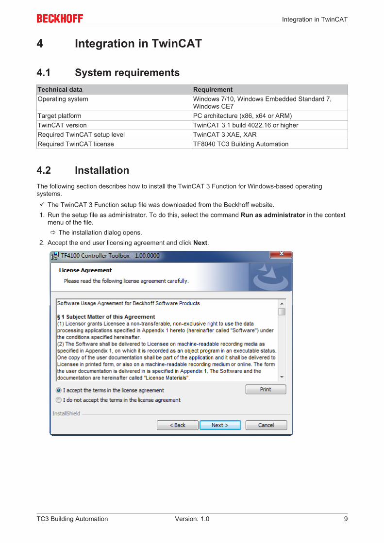
2. Accept the end user licensing agreement and click Next.
Integration in TwinCAT
TC3 Building Automation10 Version: 1.0
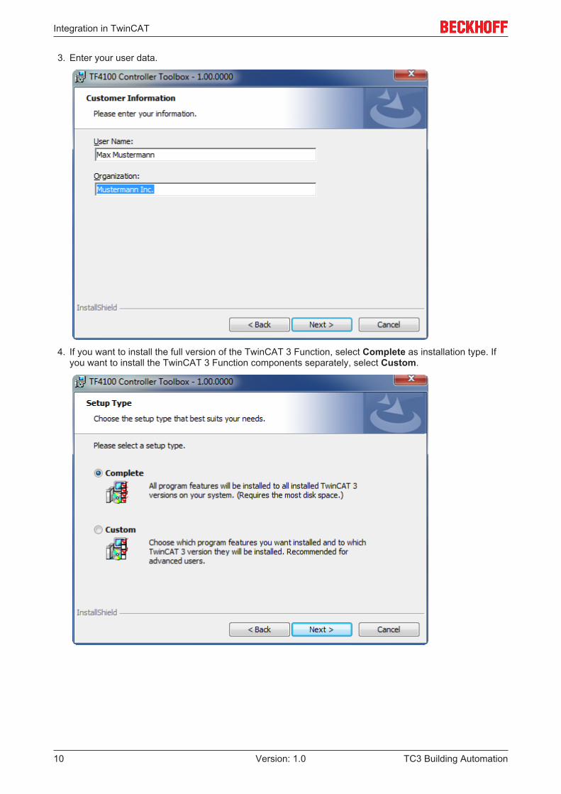
3. Enter your user data.
4. If you want to install the full version of the TwinCAT 3 Function, select Complete as installation type. Ifyou want to install the TwinCAT 3 Function components separately, select Custom.
Integration in TwinCAT
TC3 Building Automation 11Version: 1.0
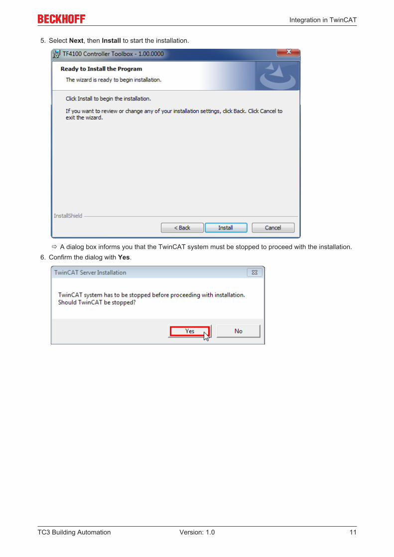
5. Select Next, then Install to start the installation.
ð A dialog box informs you that the TwinCAT system must be stopped to proceed with the installation.6. Confirm the dialog with Yes.
Integration in TwinCAT
TC3 Building Automation12 Version: 1.0
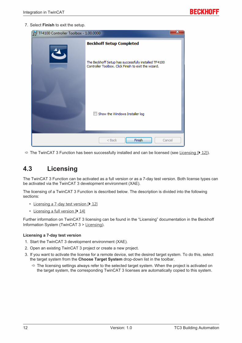
7. Select Finish to exit the setup.
ð The TwinCAT 3 Function has been successfully installed and can be licensed (see Licensing [} 12]).
4.3 LicensingThe TwinCAT 3 Function can be activated as a full version or as a 7-day test version. Both license types canbe activated via the TwinCAT 3 development environment (XAE).
The licensing of a TwinCAT 3 Function is described below. The description is divided into the followingsections:
• Licensing a 7-day test version [} 12]
• Licensing a full version [} 14]
Further information on TwinCAT 3 licensing can be found in the “Licensing” documentation in the BeckhoffInformation System (TwinCAT 3 > Licensing).
Licensing a 7-day test version1. Start the TwinCAT 3 development environment (XAE).2. Open an existing TwinCAT 3 project or create a new project.3. If you want to activate the license for a remote device, set the desired target system. To do this, select
the target system from the Choose Target System drop-down list in the toolbar.ð The licensing settings always refer to the selected target system. When the project is activated on
the target system, the corresponding TwinCAT 3 licenses are automatically copied to this system.
Integration in TwinCAT
TC3 Building Automation 13Version: 1.0
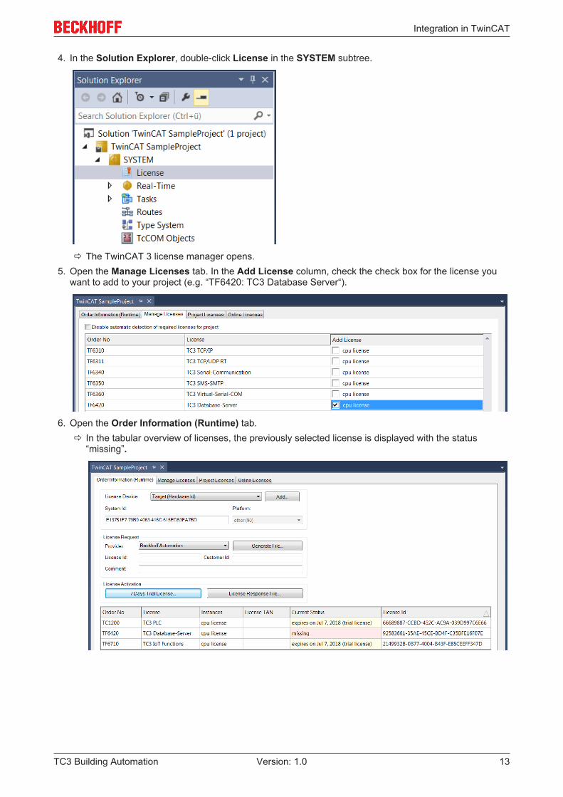
4. In the Solution Explorer, double-click License in the SYSTEM subtree.
ð The TwinCAT 3 license manager opens.5. Open the Manage Licenses tab. In the Add License column, check the check box for the license you
want to add to your project (e.g. “TF6420: TC3 Database Server“).
6. Open the Order Information (Runtime) tab.ð In the tabular overview of licenses, the previously selected license is displayed with the status
“missing”.
Integration in TwinCAT
TC3 Building Automation14 Version: 1.0
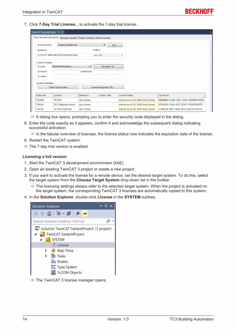
7. Click 7-Day Trial License... to activate the 7-day trial license.
ð A dialog box opens, prompting you to enter the security code displayed in the dialog.8. Enter the code exactly as it appears, confirm it and acknowledge the subsequent dialog indicating
successful activation.ð In the tabular overview of licenses, the license status now indicates the expiration date of the license.
9. Restart the TwinCAT system.ð The 7-day trial version is enabled.
Licensing a full version1. Start the TwinCAT 3 development environment (XAE).2. Open an existing TwinCAT 3 project or create a new project.3. If you want to activate the license for a remote device, set the desired target system. To do this, select
the target system from the Choose Target System drop-down list in the toolbar.ð The licensing settings always refer to the selected target system. When the project is activated on
the target system, the corresponding TwinCAT 3 licenses are automatically copied to this system.4. In the Solution Explorer, double-click License in the SYSTEM subtree.
ð The TwinCAT 3 license manager opens.
Integration in TwinCAT
TC3 Building Automation 15Version: 1.0
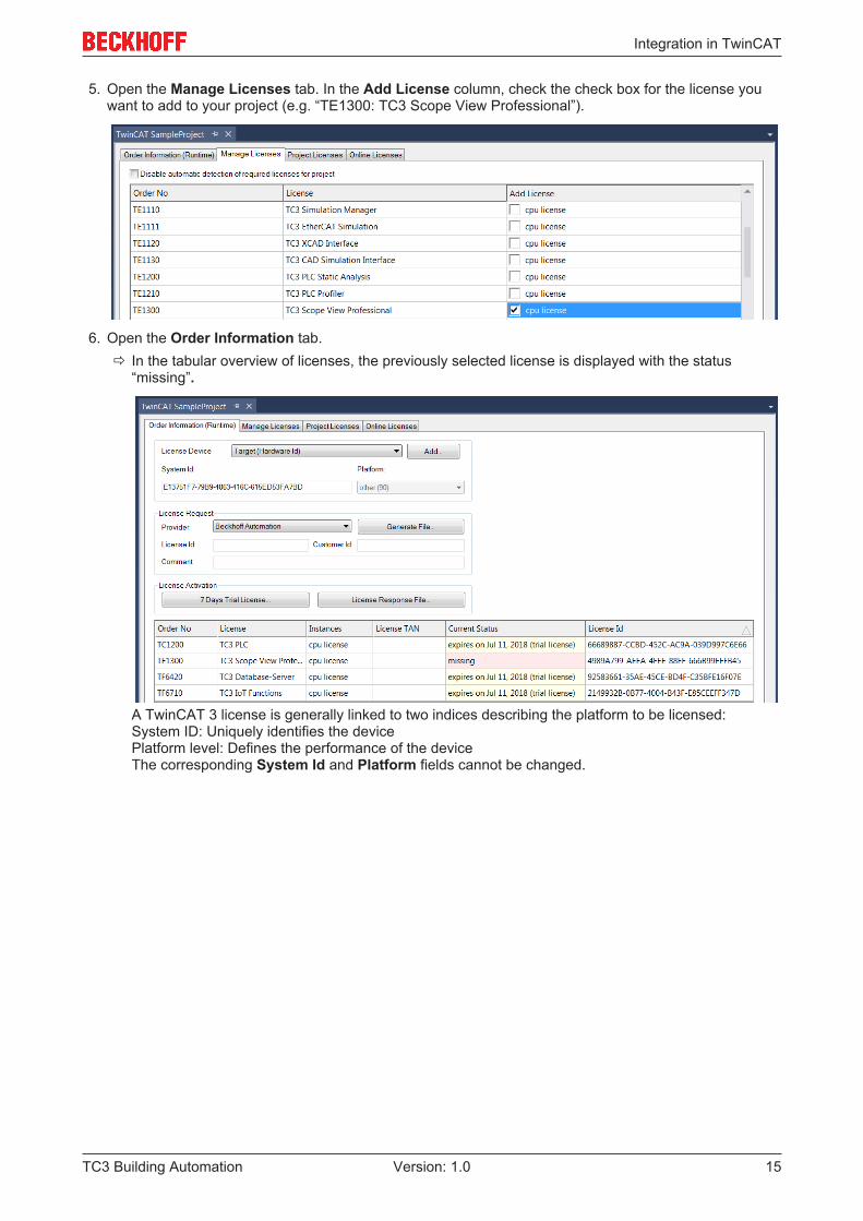
5. Open the Manage Licenses tab. In the Add License column, check the check box for the license youwant to add to your project (e.g. “TE1300: TC3 Scope View Professional”).
6. Open the Order Information tab.ð In the tabular overview of licenses, the previously selected license is displayed with the status
“missing”.
A TwinCAT 3 license is generally linked to two indices describing the platform to be licensed:System ID: Uniquely identifies the devicePlatform level: Defines the performance of the deviceThe corresponding System Id and Platform fields cannot be changed.
Integration in TwinCAT
TC3 Building Automation16 Version: 1.0
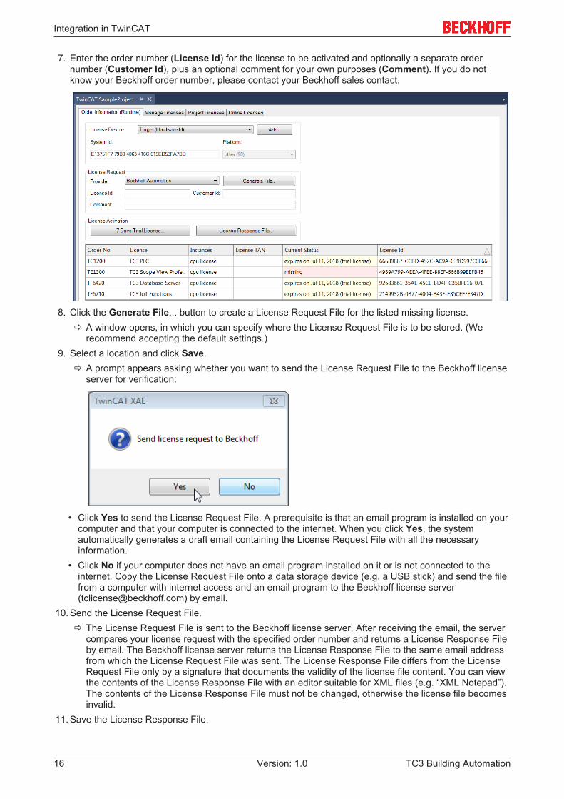
7. Enter the order number (License Id) for the license to be activated and optionally a separate ordernumber (Customer Id), plus an optional comment for your own purposes (Comment). If you do notknow your Beckhoff order number, please contact your Beckhoff sales contact.
8. Click the Generate File... button to create a License Request File for the listed missing license.ð A window opens, in which you can specify where the License Request File is to be stored. (We
recommend accepting the default settings.)9. Select a location and click Save.
ð A prompt appears asking whether you want to send the License Request File to the Beckhoff licenseserver for verification:
• Click Yes to send the License Request File. A prerequisite is that an email program is installed on yourcomputer and that your computer is connected to the internet. When you click Yes, the systemautomatically generates a draft email containing the License Request File with all the necessaryinformation.
• Click No if your computer does not have an email program installed on it or is not connected to theinternet. Copy the License Request File onto a data storage device (e.g. a USB stick) and send the filefrom a computer with internet access and an email program to the Beckhoff license server([email protected]) by email.
10. Send the License Request File.ð The License Request File is sent to the Beckhoff license server. After receiving the email, the server
compares your license request with the specified order number and returns a License Response Fileby email. The Beckhoff license server returns the License Response File to the same email addressfrom which the License Request File was sent. The License Response File differs from the LicenseRequest File only by a signature that documents the validity of the license file content. You can viewthe contents of the License Response File with an editor suitable for XML files (e.g. “XML Notepad”).The contents of the License Response File must not be changed, otherwise the license file becomesinvalid.
11. Save the License Response File.
Integration in TwinCAT
TC3 Building Automation 17Version: 1.0
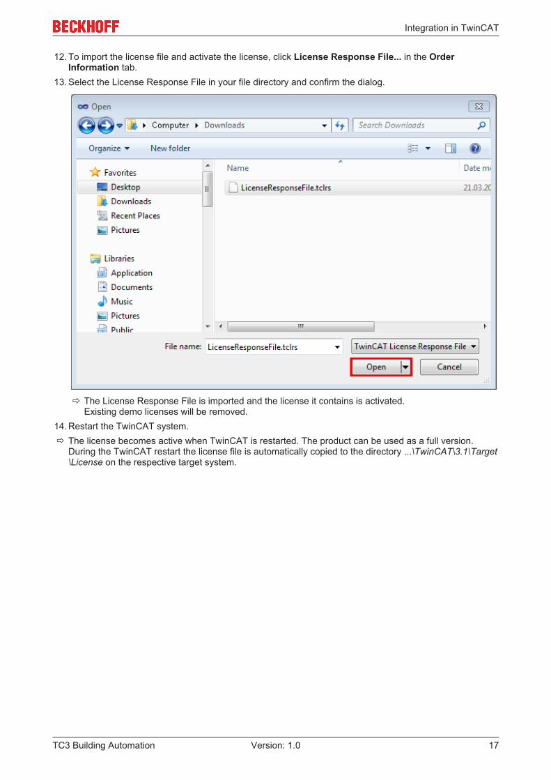
12. To import the license file and activate the license, click License Response File... in the OrderInformation tab.
13. Select the License Response File in your file directory and confirm the dialog.
ð The License Response File is imported and the license it contains is activated. Existing demo licenses will be removed.
14. Restart the TwinCAT system.ð The license becomes active when TwinCAT is restarted. The product can be used as a full version.
During the TwinCAT restart the license file is automatically copied to the directory ...\TwinCAT\3.1\Target\License on the respective target system.
Programming
TC3 Building Automation18 Version: 1.0
5 Programming
5.1 POUs
5.1.1 Air conditioning equipment
Function blocks
Name DescriptionFB_BA_FrstPrtc [} 18] Monitoring of frost alarm and emergency heating
FB_BA_HX [} 20] Calculation of dew point temperature, specificenthalpy and absolute humidity
FB_BA_NgtCol [} 21] Summer night cooling
FB_BA_RcvMonit [} 22] Function block for calculating the efficiency of anenergy recovery system
FB_BA_SPSupvis [} 25] Function block for processing and checking the lowerand upper setpoint of a supply air humidity ortemperature control
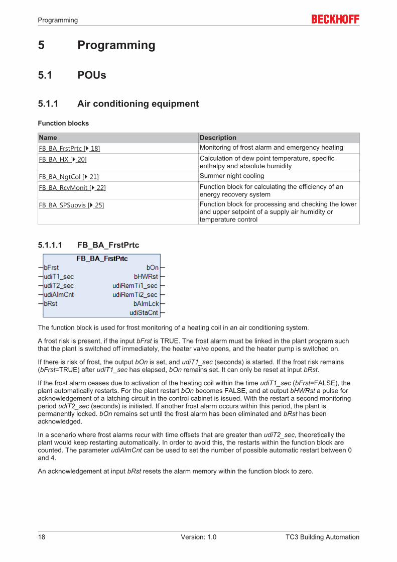
5.1.1.1 FB_BA_FrstPrtc
The function block is used for frost monitoring of a heating coil in an air conditioning system.
A frost risk is present, if the input bFrst is TRUE. The frost alarm must be linked in the plant program suchthat the plant is switched off immediately, the heater valve opens, and the heater pump is switched on.
If there is risk of frost, the output bOn is set, and udiT1_sec (seconds) is started. If the frost risk remains(bFrst=TRUE) after udiT1_sec has elapsed, bOn remains set. It can only be reset at input bRst.
If the frost alarm ceases due to activation of the heating coil within the time udiT1_sec (bFrst=FALSE), theplant automatically restarts. For the plant restart bOn becomes FALSE, and at output bHWRst a pulse foracknowledgement of a latching circuit in the control cabinet is issued. With the restart a second monitoringperiod udiT2_sec (seconds) is initiated. If another frost alarm occurs within this period, the plant ispermanently locked. bOn remains set until the frost alarm has been eliminated and bRst has beenacknowledged.
In a scenario where frost alarms recur with time offsets that are greater than udiT2_sec, theoretically theplant would keep restarting automatically. In order to avoid this, the restarts within the function block arecounted. The parameter udiAlmCnt can be used to set the number of possible automatic restart between 0and 4.
An acknowledgement at input bRst resets the alarm memory within the function block to zero.
Programming
TC3 Building Automation 19Version: 1.0
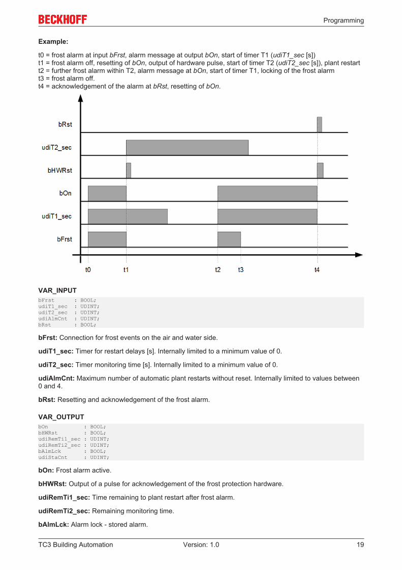
Example:
t0 = frost alarm at input bFrst, alarm message at output bOn, start of timer T1 (udiT1_sec [s])t1 = frost alarm off, resetting of bOn, output of hardware pulse, start of timer T2 (udiT2_sec [s]), plant restartt2 = further frost alarm within T2, alarm message at bOn, start of timer T1, locking of the frost alarmt3 = frost alarm off.t4 = acknowledgement of the alarm at bRst, resetting of bOn.
VAR_INPUTbFrst : BOOL;udiT1_sec : UDINT;udiT2_sec : UDINT;udiAlmCnt : UDINT;bRst : BOOL;
bFrst: Connection for frost events on the air and water side.
udiT1_sec: Timer for restart delays [s]. Internally limited to a minimum value of 0.
udiT2_sec: Timer monitoring time [s]. Internally limited to a minimum value of 0.
udiAlmCnt: Maximum number of automatic plant restarts without reset. Internally limited to values between0 and 4.
bRst: Resetting and acknowledgement of the frost alarm.
VAR_OUTPUTbOn : BOOL;bHWRst : BOOL;udiRemTi1_sec : UDINT;udiRemTi2_sec : UDINT;bAlmLck : BOOL;udiStaCnt : UDINT;
bOn: Frost alarm active.
bHWRst: Output of a pulse for acknowledgement of the frost protection hardware.
udiRemTi1_sec: Time remaining to plant restart after frost alarm.
udiRemTi2_sec: Remaining monitoring time.
bAlmLck: Alarm lock - stored alarm.
Programming
TC3 Building Automation20 Version: 1.0
udiStaCnt: Status counter – current number of unacknowledged false starts.
Requirements
Development environment required library Necessary functionTwinCAT3.1 4022.22 Tc3 Building Automation from
V1.1.0.0TF8040 | TwinCAT BuildingAutomation from V3.1.11.0
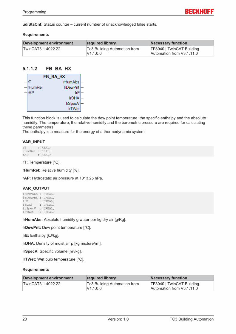
5.1.1.2 FB_BA_HX
This function block is used to calculate the dew point temperature, the specific enthalpy and the absolutehumidity. The temperature, the relative humidity and the barometric pressure are required for calculatingthese parameters.The enthalpy is a measure for the energy of a thermodynamic system.
VAR_INPUTrT : REAL;rHumRel : REAL;rAP : REAL;
rT: Temperature [°C].
rHumRel: Relative humidity [%].
rAP: Hydrostatic air pressure at 1013.25 hPa.
VAR_OUTPUTlrHumAbs : LREAL;lrDewPnt : LREAL;lrE : LREAL;lrDHA : LREAL;lrSpecV : LREAL;lrTWet : LREAL;
lrHumAbs: Absolute humidity g water per kg dry air [g/Kg].
lrDewPnt: Dew point temperature [°C].
lrE: Enthalpy [kJ/kg].
lrDHA: Density of moist air ρ [kg mixture/m³].
lrSpecV: Specific volume [m³/kg].
lrTWet: Wet bulb temperature [°C].
Requirements
Development environment required library Necessary functionTwinCAT3.1 4022.22 Tc3 Building Automation from
V1.1.0.0TF8040 | TwinCAT BuildingAutomation from V3.1.11.0
Programming
TC3 Building Automation 21Version: 1.0
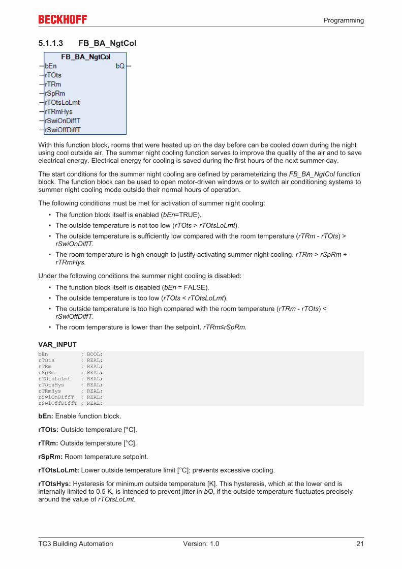
5.1.1.3 FB_BA_NgtCol
With this function block, rooms that were heated up on the day before can be cooled down during the nightusing cool outside air. The summer night cooling function serves to improve the quality of the air and to saveelectrical energy. Electrical energy for cooling is saved during the first hours of the next summer day.
The start conditions for the summer night cooling are defined by parameterizing the FB_BA_NgtCol functionblock. The function block can be used to open motor-driven windows or to switch air conditioning systems tosummer night cooling mode outside their normal hours of operation.
The following conditions must be met for activation of summer night cooling:
• The function block itself is enabled (bEn=TRUE).• The outside temperature is not too low (rTOts > rTOtsLoLmt).• The outside temperature is sufficiently low compared with the room temperature (rTRm - rTOts) >
rSwiOnDiffT.• The room temperature is high enough to justify activating summer night cooling. rTRm > rSpRm +
rTRmHys.
Under the following conditions the summer night cooling is disabled:
• The function block itself is disabled (bEn = FALSE).• The outside temperature is too low (rTOts < rTOtsLoLmt).• The outside temperature is too high compared with the room temperature (rTRm - rTOts) <
rSwiOffDiffT.• The room temperature is lower than the setpoint. rTRm≤rSpRm.
VAR_INPUTbEn : BOOL;rTOts : REAL;rTRm : REAL;rSpRm : REAL;rTOtsLoLmt : REAL;rTOtsHys : REAL;rTRmHys : REAL;rSwiOnDiffT : REAL;rSwiOffDiffT : REAL;
bEn: Enable function block.
rTOts: Outside temperature [°C].
rTRm: Outside temperature [°C].
rSpRm: Room temperature setpoint.
rTOtsLoLmt: Lower outside temperature limit [°C]; prevents excessive cooling.
rTOtsHys: Hysteresis for minimum outside temperature [K]. This hysteresis, which at the lower end isinternally limited to 0.5 K, is intended to prevent jitter in bQ, if the outside temperature fluctuates preciselyaround the value of rTOtsLoLmt.
Programming
TC3 Building Automation22 Version: 1.0
rTRmHys: Hysteresis for the room temperature [K]. This hysteresis, which at the lower end is internallylimited to 0.5 K, is intended to prevent unnecessary fluctuation of bQ, if the room temperature fluctuatesprecisely around the setpoint rSpRm.
rSwiOnDiffT: Difference between the room temperature and the outside temperature, from which summernight cooling is enabled [K].
rSwiOffDiffT: Difference between the room temperature and the outside temperature, from which summernight cooling is locked [K].
VAR_OUTPUTbQ : BOOL;
bQ: Summer night cooling on.
Requirements
Development environment required library Necessary functionTwinCAT3.1 4022.22 Tc3 Building Automation from
V1.1.0.0TF8040 | TwinCAT BuildingAutomation from V3.1.11.0
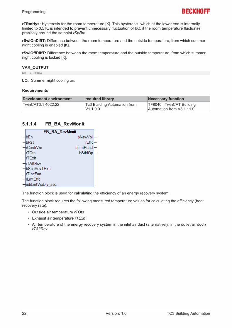
5.1.1.4 FB_BA_RcvMonit
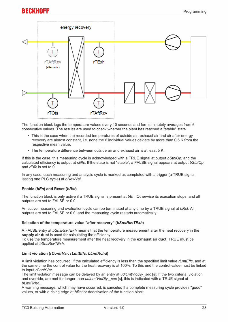
The function block is used for calculating the efficiency of an energy recovery system.
The function block requires the following measured temperature values for calculating the efficiency (heatrecovery rate):
• Outside air temperature rTOts• Exhaust air temperature rTExh• Air temperature of the energy recovery system in the inlet air duct (alternatively: in the outlet air duct)
rTAftRcv
Programming
TC3 Building Automation 23Version: 1.0
The function block logs the temperature values every 10 seconds and forms minutely averages from 6consecutive values. The results are used to check whether the plant has reached a "stable" state.
• This is the case when the recorded temperatures of outside air, exhaust air and air after energyrecovery are almost constant, i.e. none the 6 individual values deviate by more than 0.5 K from therespective mean value.
• The temperature difference between outside air and exhaust air is at least 5 K.
If this is the case, this measuring cycle is acknowledged with a TRUE signal at output bStblOp, and thecalculated efficiency is output at rEffc. If the state is not "stable", a FALSE signal appears at output bStblOp,and rEffc is set to 0.
In any case, each measuring and analysis cycle is marked as completed with a trigger (a TRUE signallasting one PLC cycle) at bNewVal.
Enable (bEn) and Reset (bRst)
The function block is only active if a TRUE signal is present at bEn. Otherwise its execution stops, and alloutputs are set to FALSE or 0.0.
An active measuring and evaluation cycle can be terminated at any time by a TRUE signal at bRst. Alloutputs are set to FALSE or 0.0, and the measuring cycle restarts automatically.
Selection of the temperature value "after recovery" (bSnsRcvTExh)
A FALSE entry at bSnsRcvTExh means that the temperature measurement after the heat recovery in thesupply air duct is used for calculating the efficiency.To use the temperature measurement after the heat recovery in the exhaust air duct, TRUE must beapplied at bSnsRcvTExh.
Limit violation (rContrVar, rLmtEffc, bLmtRchd)
A limit violation has occurred, if the calculated efficiency is less than the specified limit value rLmtEffc, and atthe same time the control value for the heat recovery is at 100%. To this end the control value must be linkedto input rContrVar.The limit violation message can be delayed by an entry at udiLmtVioDly_sec [s]: If the two criteria, violationand override, are met for longer than udiLmtVioDly _sec [s], this is indicated with a TRUE signal atbLmtRchd.A warning message, which may have occurred, is canceled if a complete measuring cycle provides "good"values, or with a rising edge at bRst or deactivation of the function block.
Programming
TC3 Building Automation24 Version: 1.0
This warning message only occurs if the plant is in a stable operating mode (bStblOp=TRUE).
Taking into account the temperature increase of the outlet air due to the fan motor (rTIncFan)
It is possible that the outlet air is warmed by a fan motor, resulting in distortion of the measurement. Thistemperature increase can be specified through rTIncFan. Internally, the measured outlet air temperature isthen reduced by this value.
VAR_INPUTbEn : BOOL;bRst : BOOL;rContrVar : REAL;rTOts : REAL;rTExh : REAL;rTAftRcv : REAL;bSnsRcvTExh : BOOL;rTIncFan : REAL;rLmtEffc : REAL;udiLmtVioDly_sec : DINT;
bEn: Function block enable.
bRst: Reset - all determined values are deleted.
rContrVar: Control value for the heat recovery, i.e. the actual value.
rTOts: Outside temperature.
rTExh: Exhaust air temperature.
rTAftRcv: Temperature after energy recovery.
bSnsRcvTExh: Temperature at the measuring point after energy recovery: FALSE -> in inlet air duct(SupplyAir) - TRUE -> in outlet air duct (ExhaustAir).
rTIncFan: Temperature increase due to fan.
rLmtEffc: Limit value efficiency.
udiLmtVioDly_sec: Limit violation delay [s]. Internally limited to a minimum value of 0.
VAR_OUTPUTbNewVal : BOOL;rEffc : REAL;bLmtRchd : BOOL;bStblOp : BOOL;
bNewVal: Output trigger for new value rEffc.
rEffc: Efficiency
bLmtRchd: Limit value reached
bStblOp: Stable operation.
Requirements
Development environment required library Necessary functionTwinCAT3.1 4022.22 Tc3 Building Automation from
V1.1.0.0TF8040 | TwinCAT BuildingAutomation from V3.1.11.0
Programming
TC3 Building Automation 25Version: 1.0
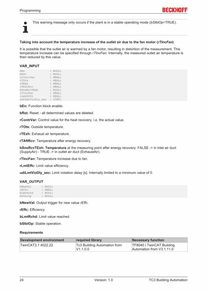
5.1.1.5 FB_BA_SpSupvis
Function block for processing and checking the lower and upper setpoint of an inlet air humidity ortemperature control.
Checking and limitation of the setpoints
The function block limits the setpoints. The following two tables show which parameters are checked andwhat the response is in the event of an error.
Checking ActionrSpLo > rSpHi last valid values of rSpLo and rSpHi are usedrSpMin >= rSpMax last valid values of rSpMin and rSpMax are usedrSpHi > rSpMax rPrSpHi = rSpMaxrSpLo < rSpMin rPrSpLo = rSpMin
Checking bErr ActionrSpMin >= rSpMax TRUE rSpErr = ((rSpMin + rSpMax) / 2)
rPrSpHi = rPrSpLo = rPrRcv =rSpErr
rSpHi < rSpMinrSpLo > rSpMax
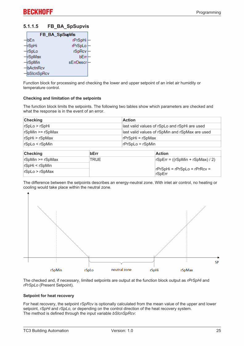
The difference between the setpoints describes an energy-neutral zone. With inlet air control, no heating orcooling would take place within the neutral zone.
The checked and, if necessary, limited setpoints are output at the function block output as rPrSpHi andrPrSpLo (Present Setpoint).
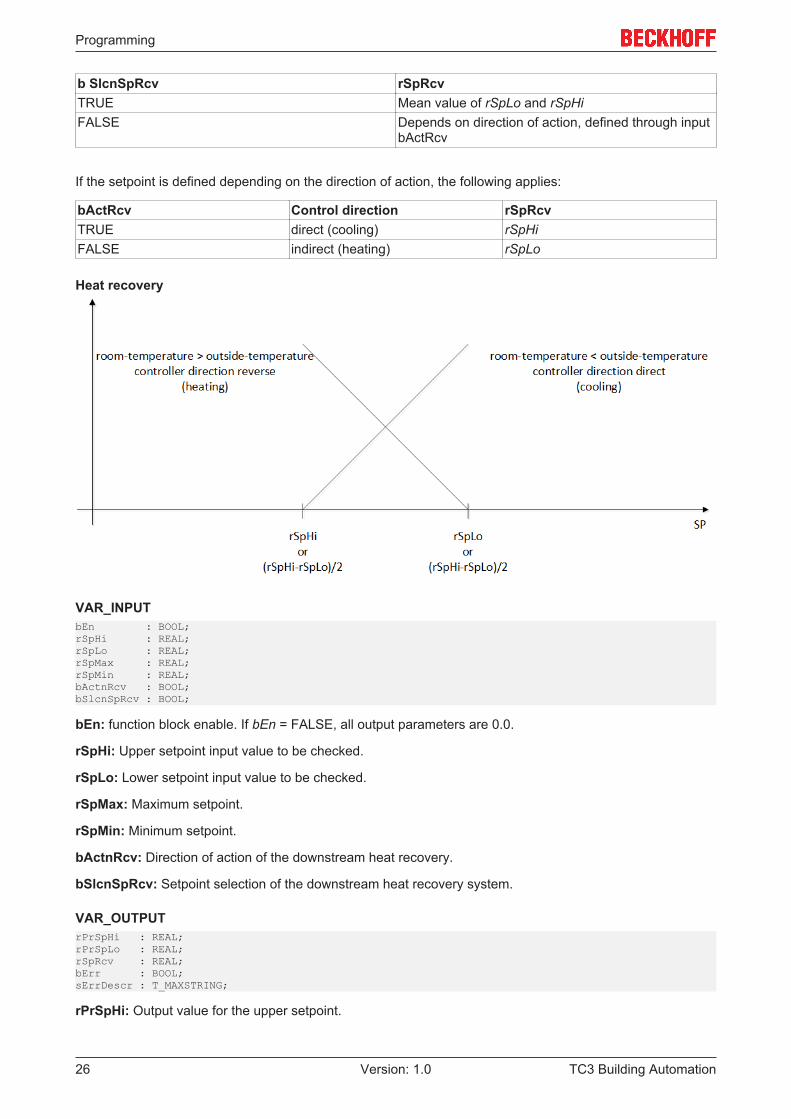
Setpoint for heat recovery
For heat recovery, the setpoint rSpRcv is optionally calculated from the mean value of the upper and lowersetpoint, rSpHi and rSpLo, or depending on the control direction of the heat recovery system.The method is defined through the input variable bSlcnSpRcv:
Programming
TC3 Building Automation26 Version: 1.0
b SlcnSpRcv rSpRcvTRUE Mean value of rSpLo and rSpHiFALSE Depends on direction of action, defined through input
bActRcv
If the setpoint is defined depending on the direction of action, the following applies:
bActRcv Control direction rSpRcv TRUE direct (cooling) rSpHiFALSE indirect (heating) rSpLo
Heat recovery
VAR_INPUTbEn : BOOL;rSpHi : REAL;rSpLo : REAL;rSpMax : REAL;rSpMin : REAL;bActnRcv : BOOL;bSlcnSpRcv : BOOL;
bEn: function block enable. If bEn = FALSE, all output parameters are 0.0.
rSpHi: Upper setpoint input value to be checked.
rSpLo: Lower setpoint input value to be checked.
rSpMax: Maximum setpoint.
rSpMin: Minimum setpoint.
bActnRcv: Direction of action of the downstream heat recovery.
bSlcnSpRcv: Setpoint selection of the downstream heat recovery system.
VAR_OUTPUTrPrSpHi : REAL;rPrSpLo : REAL;rSpRcv : REAL;bErr : BOOL;sErrDescr : T_MAXSTRING;
rPrSpHi: Output value for the upper setpoint.
Programming
TC3 Building Automation 27Version: 1.0
rPrSpLo: Output value for the lower setpoint.
rSpRcv: Output value for the resulting heat recovery setpoint.
bErr: This output is switched to TRUE if the parameters entered are erroneous.
sErrDescr: Contains the error description.
Error description01: Warning: The setpoints are not in a logical order: Either (rSpMin >= rSpMax) OR (rSpHi < rSpMin) OR(rSpLo > rSpMax)
Requirements
Development environment required library Necessary functionTwinCAT3.1 4022.22 Tc3 Building Automation from
V1.1.0.0TF8040 | TwinCAT BuildingAutomation from V3.1.11.0
5.1.2 Provision of hot water
Function blocks
Name DescriptionFB_BA_DHW2P [} 27] Charge control for a hot water tank via an on-off
controller.FB_BA_LglPrev [} 29] Function block for disinfecting service water and
destroying legionella.
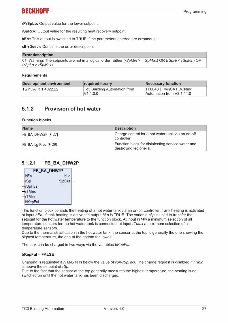
5.1.2.1 FB_BA_DHW2P
This function block controls the heating of a hot water tank via an on-off controller. Tank heating is activatedat input bEn. If tank heating is active the output bLd is TRUE. The variable rSp is used to transfer thesetpoint for the hot water temperature to the function block. At input rTMin a minimum selection of alltemperature sensors for the hot water tank is connected, at input rTMax a maximum selection of alltemperature sensors.Due to the thermal stratification in the hot water tank, the sensor at the top is generally the one showing thehighest temperature, the one at the bottom the lowest.
The tank can be charged in two ways via the variables bKepFul:
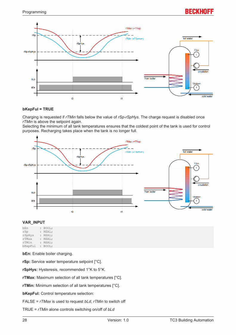
bKepFul = FALSE
Charging is requested if rTMax falls below the value of rSp-rSpHys. The charge request is disabled if rTMinis above the setpoint of rSp.Due to the fact that the sensor at the top generally measures the highest temperature, the heating is notswitched on until the hot water tank has been discharged.
Programming
TC3 Building Automation28 Version: 1.0
bKepFul = TRUE
Charging is requested if rTMin falls below the value of rSp-rSpHys. The charge request is disabled oncerTMin is above the setpoint again.Selecting the minimum of all tank temperatures ensures that the coldest point of the tank is used for controlpurposes. Recharging takes place when the tank is no longer full.
VAR_INPUTbEn : BOOL;rSp : REAL;rSpHys : REAL;rTMax : REAL;rTMin : REAL;bKepFul : BOOL;
bEn: Enable boiler charging.
rSp: Service water temperature setpoint [°C].
rSpHys: Hysteresis, recommended 1°K to 5°K.
rTMax: Maximum selection of all tank temperatures [°C].
rTMin: Minimum selection of all tank temperatures [°C].
bKepFul: Control temperature selection:
FALSE = rTMax is used to request bLd, rTMin to switch off
TRUE = rTMin alone controls switching on/off of bLd
Programming
TC3 Building Automation 29Version: 1.0
VAR_OUTPUTbLd : BOOL;rSpOut : REAL;
bLd: Enable charging mode.
rSpOut: Setpoint transfer to charging circuit:
• rSpOut = rSp (input) if the function block is enabled• rSpOut = 0 if the function block is not enabled
Requirements
Development environment required library Necessary functionTwinCAT3.1 4022.22 Tc3 Building Automation from
V1.1.0.0TF8040 | TwinCAT BuildingAutomation from V3.1.11.0
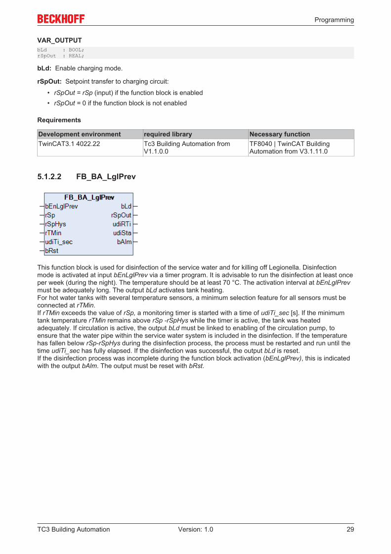
5.1.2.2 FB_BA_LglPrev
This function block is used for disinfection of the service water and for killing off Legionella. Disinfectionmode is activated at input bEnLglPrev via a timer program. It is advisable to run the disinfection at least onceper week (during the night). The temperature should be at least 70 °C. The activation interval at bEnLglPrevmust be adequately long. The output bLd activates tank heating.For hot water tanks with several temperature sensors, a minimum selection feature for all sensors must beconnected at rTMin.If rTMin exceeds the value of rSp, a monitoring timer is started with a time of udiTi_sec [s]. If the minimumtank temperature rTMin remains above rSp -rSpHys while the timer is active, the tank was heatedadequately. If circulation is active, the output bLd must be linked to enabling of the circulation pump, toensure that the water pipe within the service water system is included in the disinfection. If the temperaturehas fallen below rSp-rSpHys during the disinfection process, the process must be restarted and run until thetime udiTi_sec has fully elapsed. If the disinfection was successful, the output bLd is reset.If the disinfection process was incomplete during the function block activation (bEnLglPrev), this is indicatedwith the output bAlm. The output must be reset with bRst.
Programming
TC3 Building Automation30 Version: 1.0
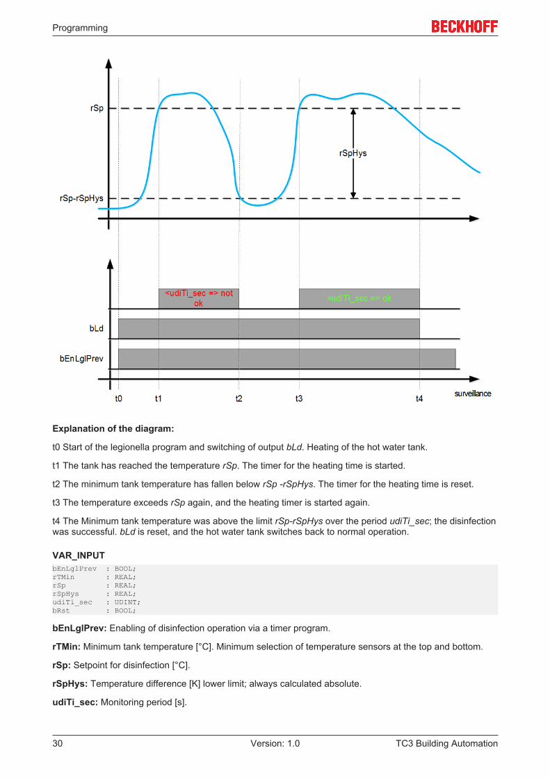
Explanation of the diagram:
t0 Start of the legionella program and switching of output bLd. Heating of the hot water tank.
t1 The tank has reached the temperature rSp. The timer for the heating time is started.
t2 The minimum tank temperature has fallen below rSp -rSpHys. The timer for the heating time is reset.
t3 The temperature exceeds rSp again, and the heating timer is started again.
t4 The Minimum tank temperature was above the limit rSp-rSpHys over the period udiTi_sec; the disinfectionwas successful. bLd is reset, and the hot water tank switches back to normal operation.
VAR_INPUTbEnLglPrev : BOOL;rTMin : REAL;rSp : REAL;rSpHys : REAL;udiTi_sec : UDINT;bRst : BOOL;
bEnLglPrev: Enabling of disinfection operation via a timer program.
rTMin: Minimum tank temperature [°C]. Minimum selection of temperature sensors at the top and bottom.
rSp: Setpoint for disinfection [°C].
rSpHys: Temperature difference [K] lower limit; always calculated absolute.
udiTi_sec: Monitoring period [s].
Programming
TC3 Building Automation 31Version: 1.0
bRst: Resetting of the legionella alarm;
VAR_OUTPUTbLd : BOOL;rSpOut : REAL;udiRTi : UDINT;udiSta : UDINT;
bLd: Anti-legionella mode active.
rSpOut: Setpoint transfer to charging circuit:
• rSp (input) if the function block is enabled• 0 if the function block is not enabled
udiRTi: Disinfection mode timer countdown.
udiSta: Disinfection program status:
1. The disinfection operation was successful.2. The disinfection was completed successfully. After the disinfection, and to reactivate legionella pre-
vention, bEnLglPrev must be FALSE.3. The disinfection operation is active.4. Disinfection was not successful. Alarm is pending.5. Disinfection was not successful, the alarm was acknowledged.6. Controller restart, or legionella mode has not yet been requested.
bAlm: The temperature setpoint was not reached consistently over via the interval udiTi_sec, so thatadequate disinfection is not guaranteed.
Requirements
Development environment required library Necessary functionTwinCAT3.1 4022.22 Tc3 Building Automation from
V1.1.0.0TF8040 | TwinCAT BuildingAutomation from V3.1.11.0
5.1.3 Room automation
5.1.3.1 Heating, cooling
Function blocks
Name DescriptionFB_BA_FnctSel [} 32] Function selection (heating and/or cooling) in two- or
four-pipe network.FB_BA_RmTAdj [} 35] Adjustment of the room temperature setpoint.
FB_BA_SpRmT [} 38] Adjustment of the room temperature setpoint
Programming
TC3 Building Automation32 Version: 1.0
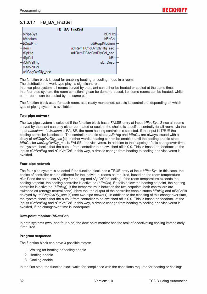
5.1.3.1.1 FB_BA_FnctSel
The function block is used for enabling heating or cooling mode in a room.The distribution network type plays a significant role: In a two-pipe system, all rooms served by the plant can either be heated or cooled at the same time. In a four-pipe system, the room conditioning can be demand-based, i.e. some rooms can be heated, whileother rooms can be cooled by the same plant.
The function block used for each room, as already mentioned, selects its controllers, depending on whichtype of piping system is available:
Two-pipe network
The two-pipe system is selected if the function block has a FALSE entry at input bPipeSys. Since all roomsserved by the plant can only either be heated or cooled, the choice is specified centrally for all rooms via theinput bMedium. If bMedium is FALSE, the room heating controller is selected. If the input is TRUE thecooling controller is selected. The controller enable states bEnHtg and bEnCol are always issued with adelay of udiChgOvrDly_sec [s]. In other words, heating cannot be enabled until the cooling enable statebEnCol for udiChgOvrDly_sec is FALSE, and vice versa. In addition to the elapsing of this changeover time,the system checks that the output from controller to be switched off is 0.0. This is based on feedback at theinputs rCtrlValHtg and rCtrlValCol. In this way, a drastic change from heating to cooling and vice versa isavoided.
Four-pipe network
The four-pipe system is selected if the function block has a TRUE entry at input bPipeSys. In this case, thechoice of controller can be different for the individual rooms as required, based on the room temperaturerRmT and the setpoints rSpHtg for heating and rSpCol for cooling. If the room temperature exceeds thecooling setpoint, the cooling controller is activated (bEnCol), if it falls below the heating setpoint, the heatingcontroller is activated (bEnHtg). If the temperature is between the two setpoints, both controllers areswitched off (energy-neutral zone). Here too, the output of the controller enable states bEnHtg and bEnCol isdelayed by udiChgOvrDly_sec [s] (see two-pipe network). In addition to the elapsing of this changeover time,the system checks that the output from controller to be switched off is 0.0. This is based on feedback at theinputs rCtrlValHtg and rCtrlValCol. In this way, a drastic change from heating to cooling and vice versa isavoided, if the changeover time is inadequate.
Dew-point monitor (bDewPnt)
In both systems (two- and four-pipe) the dew-point monitor has the task of deactivating cooling immediately,if required.
Program sequence
The function block can have 3 possible states:
1. Waiting for heating or cooling enable2. Heating enable3. Cooling enable
In the first step, the function block waits for compliance with the conditions required for heating or cooling:
Programming
TC3 Building Automation 33Version: 1.0
Heating Cooling Cooling controller output = 0 (rCtrlValCol) Heating controller output = 0 (rCtrlValHtg)Room temperature (rRmT) < heating setpoint(rSpHtg)
Room temperature (rRmT) > cooling setpoint(rSpCol)
Cooling controller enable (bEnCol) is FALSE over atleast the changeover time udiChgOvrDly_sec [s]
Heating controller enable (bEnHtg) is FALSE over atleast the changeover time udiChgOvrDly_sec [s]
Four-pipe system is selected (bPipesys=TRUE)OR two-pipe system is selected and heating mediumis available (bPipeSys=FALSE ANDbMedium=FALSE)
Four-pipe system is selected (bPipesys=TRUE)OR two-pipe system is selected and cooling mediumis available (bPipeSys=FALSE ANDbMedium=TRUE)The dew-point monitor does not respond(bDewPnt=TRUE)
If a chain of conditions is met, the function block switches to the respective state (heating or cooling) andremains in this state until the corresponding controller issues 0 at the function block input (rCtrlValHtg/rCtrlValCol). This ensures that only one controller is active at any one time, even if a high heating controlleroutput, for example, would call for a brief cooling intervention (overshoot). Heating or cooling continues untilthere is no longer a demand.
There are 3 exceptions, for which heating or cooling is immediately interrupted:
1. A two-pipe system (bPipeSys=FALSE) is in heating mode (bEnHtg), but a switch to cooling mediumoccurred bMedium=TRUE
2. A two-pipe system (bPipeSys=FALSE) is in cooling mode (bEnCol), but a switch to heating mediumoccurred bMedium=FALSE
3. The dew-point monitor was triggered (bDewPnt=TRUE) in cooling mode (two- or four-pipe system)
In these cases the heating or cooling enable states are canceled, and the plant switches to standby.
Demand message (udireqdMedium)
To notify the plant of the current demand for heating or cooling, a demand ID is issued at the function blockoutput, i.e. for each room, depending on the actual and set temperature. These can be collected andevaluated centrally. The evaluation always takes place, irrespective of the network type (two- or four-pipe).
udiReqdMedium Medium Room temperature1 No medium is requested rRmT > rSpHtg AND rRmT <
rSpCol2 Heating medium is requested rRmT < rSpHtg3 Cooling medium is requested rRmT > rSpCol
Error handling
The heating setpoint must not be greater than or equal to the cooling setpoint, since this would result intemperature range with simultaneous heating and cooling demand. However, since the function block onlyissues one enable state at a time (i.e. heating or cooling), the case is harmless from a plant engineeringperspective. In this case only a warning message is issued (bErr=TRUE, sErrDescr=warning message); thefunction block does not interrupt its cycle.
VAR_INPUTbPipeSys : BOOL;bMedium : BOOL;bDewPnt : BOOL;rRmT : REAL;rSpHtg : REAL;rSpCol : REAL;rCtrlValHtg : REAL;rCtrlValCol : REAL;udiChgOvrDel_sec : UDINT;
bPipeSys: In two-pipe system bPipeSys is FALSE, in four-pipe systems it is TRUE.
Programming
TC3 Building Automation34 Version: 1.0
bMedium: Current supply of the whole two-pipe network with cooling or heating medium. If heating mediumis active, bMedium is FALSE.
bDewPnt: Dew-point monitor: If bDewPnt = TRUE, the cooling controller is locked.
rTRm: Room temperature.
rSpHtg: Heating setpoint.
rSpCol: Cooling setpoint.
rCtrlValHtg: Current output value of the heating controller. Used internally as switching criterion fromheating to cooling: rCtrlValHtg must be 0.
rCtrlValCol: Current output value of the cooling controller. Used internally as switching criterion from coolingto heating: rCtrlValCol must be 0.
udiChgOvrDel_sec: Switchover delay [s] from heating to cooling or vice versa. Internally limited to aminimum value of 0.
VAR_OUTPUTbEnHtg : BOOL;bEnCol : BOOL;udiReqdMedium : UDINT;udiRemTiChgOvrDlyHtg_sec : UDINT;udiRemTiChgOvrDlyCol_sec : UDINT;bErr : BOOL;sErrDescr : T_MAXSTRING;
bEnHtg: Heating controller enable.
bEnCol: Cooling controller enable.
udiReqdMedium:
udiReqdMedium Medium Room temperature 1 No medium is requested rRmT > rSpHtg AND rRmT <
rSpCol2 Heating medium is requested rRmT < rSpHtg3 Cooling medium is requested rRmT > rSpCol
udiRemTiChgOvrDlyHtg_sec: Countdown [s] for switchover delay from cooling to heating.
udiRemTiChgOvrDlyCol_sec: Countdown [s] for switchover delay from heating to cooling.
bErr: In case of a fault, e.g. if warning stages are active, this output is set to TRUE.
sErrDescr: Contains the error description.
Error description01: Warning: The heating setpoint is higher than or equal to the cooling setpoint
Requirements
Development environment required library Necessary functionTwinCAT3.1 4022.22 Tc3 Building Automation from
V1.1.0.0TF8040 | TwinCAT BuildingAutomation from V3.1.11.0
Programming
TC3 Building Automation 35Version: 1.0
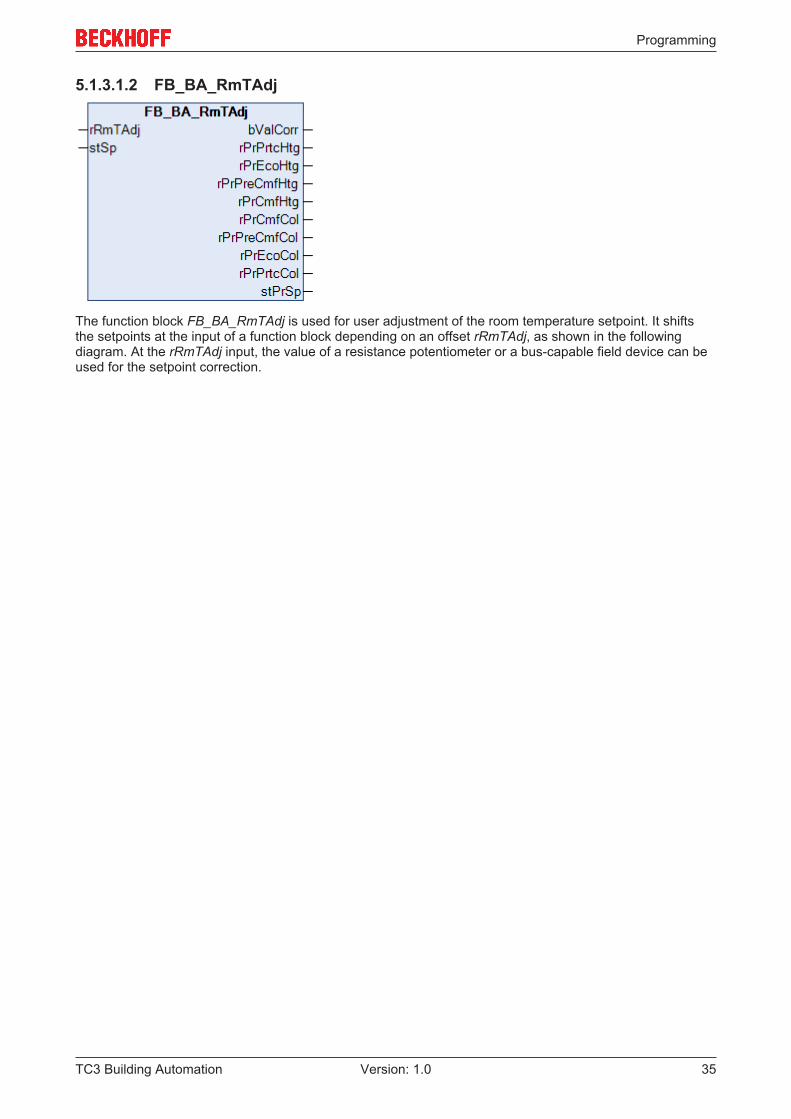
5.1.3.1.2 FB_BA_RmTAdj
The function block FB_BA_RmTAdj is used for user adjustment of the room temperature setpoint. It shiftsthe setpoints at the input of a function block depending on an offset rRmTAdj, as shown in the followingdiagram. At the rRmTAdj input, the value of a resistance potentiometer or a bus-capable field device can beused for the setpoint correction.
Programming
TC3 Building Automation36 Version: 1.0
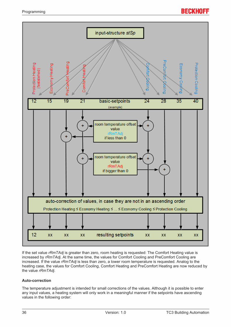
If the set value rRmTAdj is greater than zero, room heating is requested: The Comfort Heating value isincreased by rRmTAdj. At the same time, the values for Comfort Cooling and PreComfort Cooling areincreased. If the value rRmTAdj is less than zero, a lower room temperature is requested. Analog to theheating case, the values for Comfort Cooling, Comfort Heating and PreComfort Heating are now reduced bythe value rRmTAdj.
Auto-correction
The temperature adjustment is intended for small corrections of the values. Although it is possible to enterany input values, a heating system will only work in a meaningful manner if the setpoints have ascendingvalues in the following order:
Programming
TC3 Building Automation 37Version: 1.0
• Protection Heating• Economy Heating• Precomfort Heating• Comfort Heating• Comfort Cooling• Precomfort Cooling• Economy Cooling• Protection Cooling
Auto-correction works according to the following principle: Starting with the value Economy Heating, thesystem checks whether this value is smaller than the lower value of Protection Heating. If this is the case,the value for Economy Heating is adjusted to match the value for Protection Heating. The system thenchecks whether the value for Precomfort Heating is less than Economy Heating and so on, until the value forProtection Cooling is compared with the value for Economy Cooling. If one or several values were corrected,this is indicated with a TRUE signal at output bValCorr.
VAR_INPUTrRmTAdj : REAL;stSp : ST_BA_SpRmT;
rRmTAdj: Room temperature offset value.
stSp: Input structure for the setpoints (see ST_BA_SpRmT [} 183]).
VAR_OUTPUTbValCorr : BOOL;rPrPrtcHtg : REAL;rPrEcoHtg : REAL;rPrPreCmfHtg : REAL;rPrCmfHtg : REAL;rPrPrtcCol : REAL;rPrEcoCol : REAL;rPrPreCmfCol : REAL;rPrCmfCol : REAL;stPrSp : ST_BA_SpRmT;
bValCorr: Autocorrection for the values was performed, see above.
rPrPrtcHtg: Resulting Protection Heating setpoint.
rPrEcoHtg: Resulting Economy Heating setpoint.
rPrPreCmfHtg: Resulting PreComfort Heating setpoint.
rPrCmfHtg: Resulting Comfort Heating setpoint.
rPrCmfCol: Resulting Comfort Cooling setpoint.
rPrPreCmfCol: Resulting PreComfort Cooling setpoint.
rPrEcoCol: Resulting Economy Cooling setpoint.
rPrPrtcCol: Resulting Protection Cooling setpoint.
stPrSp: Consolidated output of the resulting values in a structure (see ST_BA_SpRmT [} 183]).
Requirements
Development environment required library Necessary functionTwinCAT3.1 4022.22 Tc3 Building Automation from
V1.1.0.0TF8040 | TwinCAT BuildingAutomation from V3.1.11.0
Programming
TC3 Building Automation38 Version: 1.0
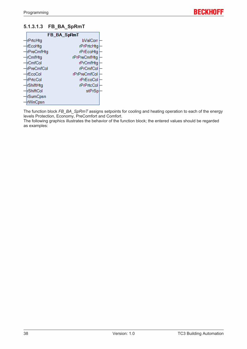
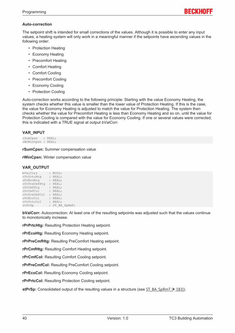
5.1.3.1.3 FB_BA_SpRmT
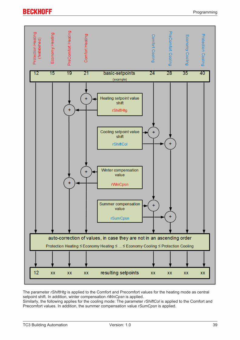
The function block FB_BA_SpRmT assigns setpoints for cooling and heating operation to each of the energylevels Protection, Economy, PreComfort and Comfort.The following graphics illustrates the behavior of the function block; the entered values should be regardedas examples:
Programming
TC3 Building Automation 39Version: 1.0
The parameter rShiftHtg is applied to the Comfort and Precomfort values for the heating mode as centralsetpoint shift. In addition, winter compensation rWinCpsn is applied.Similarly, the following applies for the cooling mode: The parameter rShiftCol is applied to the Comfort andPrecomfort values. In addition, the summer compensation value rSumCpsn is applied.
Programming
TC3 Building Automation40 Version: 1.0
Auto-correction
The setpoint shift is intended for small corrections of the values. Although it is possible to enter any inputvalues, a heating system will only work in a meaningful manner if the setpoints have ascending values in thefollowing order:
• Protection Heating• Economy Heating• Precomfort Heating• Comfort Heating• Comfort Cooling• Precomfort Cooling• Economy Cooling• Protection Cooling
Auto-correction works according to the following principle: Starting with the value Economy Heating, thesystem checks whether this value is smaller than the lower value of Protection Heating. If this is the case,the value for Economy Heating is adjusted to match the value for Protection Heating. The system thenchecks whether the value for Precomfort Heating is less than Economy Heating and so on, until the value forProtection Cooling is compared with the value for Economy Cooling. If one or several values were corrected,this is indicated with a TRUE signal at output bValCorr.
VAR_INPUTrSumCpsn : REAL;rWrWinCpsn : REAL;
rSumCpsn: Summer compensation value
rWinCpsn: Winter compensation value
VAR_OUTPUTbValCorr : BOOL;rPrPrtcHtg : REAL;rPrEcoHtg : REAL;rPrPreCmfHtg : REAL;rPrCmfHtg : REAL;rPrCmfCol : REAL;rPrPreCmfCol : REAL;rPrEcoCol : REAL;rPrPrtcCol : REAL;stPrSp : ST_BA_SpRmT;
bValCorr: Autocorrection: At least one of the resulting setpoints was adjusted such that the values continueto monotonically increase.
rPrPrtcHtg: Resulting Protection Heating setpoint.
rPrEcoHtg: Resulting Economy Heating setpoint.
rPrPreCmfHtg: Resulting PreComfort Heating setpoint.
rPrCmfHtg: Resulting Comfort Heating setpoint.
rPrCmfCol: Resulting Comfort Cooling setpoint.
rPrPreCmfCol: Resulting PreComfort Cooling setpoint.
rPrEcoCol: Resulting Economy Cooling setpoint.
rPrPrtcCol: Resulting Protection Cooling setpoint.
stPrSp: Consolidated output of the resulting values in a structure (see ST_BA_SpRmT [} 183]).

Programming
TC3 Building Automation 41Version: 1.0
VAR_INPUT_CONSTANT_PERSISTENT (Parameter)rShiftCol : REAL := 0;rShiftHtg : REAL := 0;rPrtcCol : REAL := 35;rEcoCol : REAL := 28;rPreCmfCol : REAL := 25;rCmfCol : REAL := 23;rCmfHtg : REAL := 21;rPreCmfHtg : REAL := 18;rEcoHtg : REAL := 14;rPrtcHtg : REAL := 6;
rShiftCol: Cooling setpoint value shift.
rShiftHtg: Heating setpoint value shift.
rPrtcCol: Basic Protection Cooling setpoint.
rEcoCol: Basic Economy Cooling setpoint.
rPreCmfCol: Basic PreComfort Cooling setpoint.
rCmfCol: Basic Comfort Cooling setpoint.
rCmfHtg: Basic Comfort Heating setpoint.
rPreCmfHtg: Basic PreComfort Heating setpoint.
rEcoHtg: Basic Economy Heating setpoint.
rPrtcHtg: Basic Protection Heating setpoint.
Requirements
Development environment required library Necessary functionTwinCAT3.1 4022.22 Tc3 Building Automation from
V1.1.0.0TF8040 | TwinCAT BuildingAutomation from V3.1.11.0
5.1.3.2 Lighting
Function blocks
Name DescriptionFB_BA_Toggle [} 41] Switching of lamps.
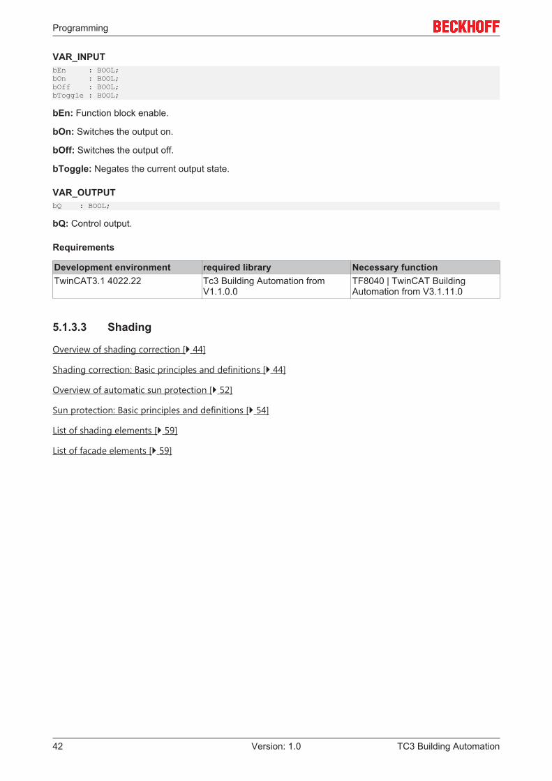
5.1.3.2.1 FB_BA_Toggle
The function block is used to switch an actuator on or off.
The input bEn is used for enabling the function block.A positive edge at the input bOn results in setting of output bQ. The output is reset by a rising edge at thebOff input. If a rising edge is presented to bToggle, the output is negated; i.e., if On it goes Off, and if Off itgoes On.
Programming
TC3 Building Automation42 Version: 1.0
VAR_INPUTbEn : BOOL;bOn : BOOL;bOff : BOOL;bToggle : BOOL;
bEn: Function block enable.
bOn: Switches the output on.
bOff: Switches the output off.
bToggle: Negates the current output state.
VAR_OUTPUTbQ : BOOL;
bQ: Control output.
Requirements
Development environment required library Necessary functionTwinCAT3.1 4022.22 Tc3 Building Automation from
V1.1.0.0TF8040 | TwinCAT BuildingAutomation from V3.1.11.0
5.1.3.3 Shading
Overview of shading correction [} 44]
Shading correction: Basic principles and definitions [} 44]
Overview of automatic sun protection [} 52]
Sun protection: Basic principles and definitions [} 54]
List of shading elements [} 59]
List of facade elements [} 59]
Programming
TC3 Building Automation 43Version: 1.0
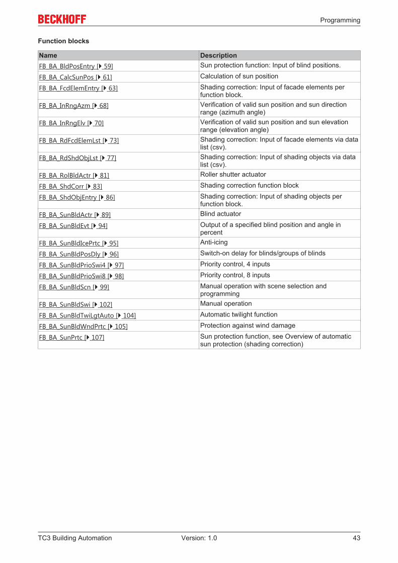
Function blocks
Name DescriptionFB_BA_BldPosEntry [} 59] Sun protection function: Input of blind positions.
FB_BA_CalcSunPos [} 61] Calculation of sun position
FB_BA_FcdElemEntry [} 63] Shading correction: Input of facade elements perfunction block.
FB_BA_InRngAzm [} 68] Verification of valid sun position and sun directionrange (azimuth angle)
FB_BA_InRngElv [} 70] Verification of valid sun position and sun elevationrange (elevation angle)
FB_BA_RdFcdElemLst [} 73] Shading correction: Input of facade elements via datalist (csv).
FB_BA_RdShdObjLst [} 77] Shading correction: Input of shading objects via datalist (csv).
FB_BA_RolBldActr [} 81] Roller shutter actuator
FB_BA_ShdCorr [} 83] Shading correction function block
FB_BA_ShdObjEntry [} 86] Shading correction: Input of shading objects perfunction block.
FB_BA_SunBldActr [} 89] Blind actuator
FB_BA_SunBldEvt [} 94] Output of a specified blind position and angle inpercent
FB_BA_SunBldIcePrtc [} 95] Anti-icing
FB_BA_SunBldPosDly [} 96] Switch-on delay for blinds/groups of blinds
FB_BA_SunBldPrioSwi4 [} 97] Priority control, 4 inputs
FB_BA_SunBldPrioSwi8 [} 98] Priority control, 8 inputs
FB_BA_SunBldScn [} 99] Manual operation with scene selection andprogramming
FB_BA_SunBldSwi [} 102] Manual operation
FB_BA_SunBldTwiLgtAuto [} 104] Automatic twilight function
FB_BA_SunBldWndPrtc [} 105] Protection against wind damage
FB_BA_SunPrtc [} 107] Sun protection function, see Overview of automaticsun protection (shading correction)
Programming
TC3 Building Automation44 Version: 1.0
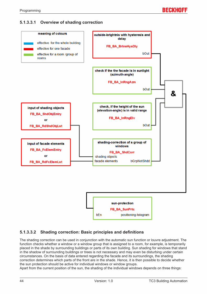
5.1.3.3.1 Overview of shading correction
5.1.3.3.2 Shading correction: Basic principles and definitions
The shading correction can be used in conjunction with the automatic sun function or louvre adjustment. Thefunction checks whether a window or a window group that is assigned to a room, for example, is temporarilyplaced in the shade by surrounding buildings or parts of its own building. Sun shading for windows that standin the shadow of surrounding buildings or trees is not necessary and may even be disturbing under certaincircumstances. On the basis of data entered regarding the facade and its surroundings, the shadingcorrection determines which parts of the front are in the shade. Hence, it is then possible to decide whetherthe sun protection should be active for individual windows or window groups.Apart from the current position of the sun, the shading of the individual windows depends on three things:
Programming
TC3 Building Automation 45Version: 1.0
• the orientation of the facade• the position of the windows• the positioning of the shading objects
The following illustrations are intended to describe these interrelationships and to present the parameters tobe entered.
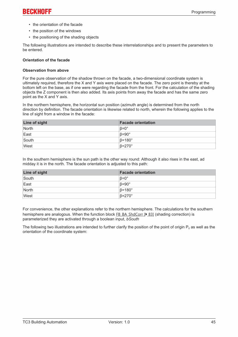
Orientation of the facade
Observation from above
For the pure observation of the shadow thrown on the facade, a two-dimensional coordinate system isultimately required, therefore the X and Y axis were placed on the facade. The zero point is thereby at thebottom left on the base, as if one were regarding the facade from the front. For the calculation of the shadingobjects the Z component is then also added. Its axis points from away the facade and has the same zeropoint as the X and Y axis.
In the northern hemisphere, the horizontal sun position (azimuth angle) is determined from the northdirection by definition. The facade orientation is likewise related to north, wherein the following applies to theline of sight from a window in the facade:
Line of sight Facade orientationNorth β=0°East β=90°South β=180°West β=270°
In the southern hemisphere is the sun path is the other way round: Although it also rises in the east, admidday it is in the north. The facade orientation is adjusted to this path:
Line of sight Facade orientationSouth β=0°East β=90°North β=180°West β=270°
For convenience, the other explanations refer to the northern hemisphere. The calculations for the southernhemisphere are analogous. When the function block FB_BA_ShdCorr [} 83] (shading correction) isparameterized they are activated through a boolean input, bSouth
The following two illustrations are intended to further clarify the position of the point of origin P0 as well as theorientation of the coordinate system:
Programming
TC3 Building Automation46 Version: 1.0
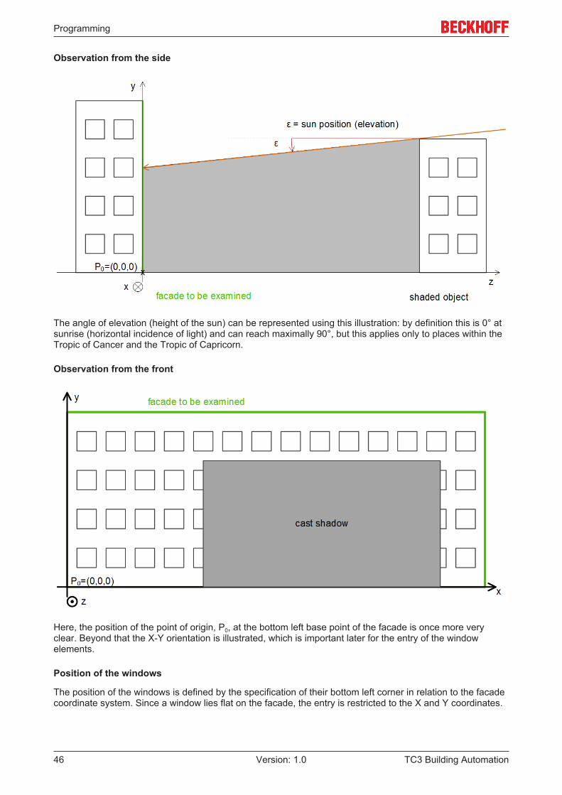
Observation from the side
The angle of elevation (height of the sun) can be represented using this illustration: by definition this is 0° atsunrise (horizontal incidence of light) and can reach maximally 90°, but this applies only to places within theTropic of Cancer and the Tropic of Capricorn.
Observation from the front
Here, the position of the point of origin, P0, at the bottom left base point of the facade is once more veryclear. Beyond that the X-Y orientation is illustrated, which is important later for the entry of the windowelements.
Position of the windows
The position of the windows is defined by the specification of their bottom left corner in relation to the facadecoordinate system. Since a window lies flat on the facade, the entry is restricted to the X and Y coordinates.
Programming
TC3 Building Automation 47Version: 1.0
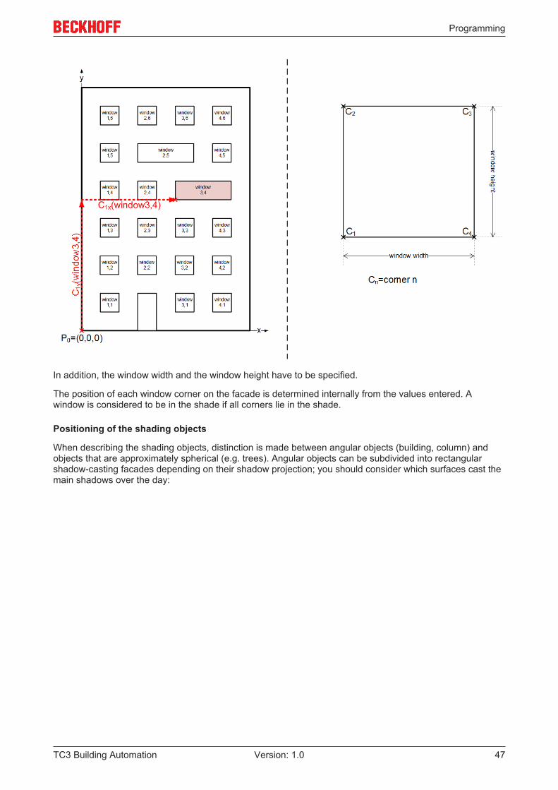
In addition, the window width and the window height have to be specified.
The position of each window corner on the facade is determined internally from the values entered. Awindow is considered to be in the shade if all corners lie in the shade.
Positioning of the shading objects
When describing the shading objects, distinction is made between angular objects (building, column) andobjects that are approximately spherical (e.g. trees). Angular objects can be subdivided into rectangularshadow-casting facades depending on their shadow projection; you should consider which surfaces cast themain shadows over the day:
Programming
TC3 Building Automation48 Version: 1.0
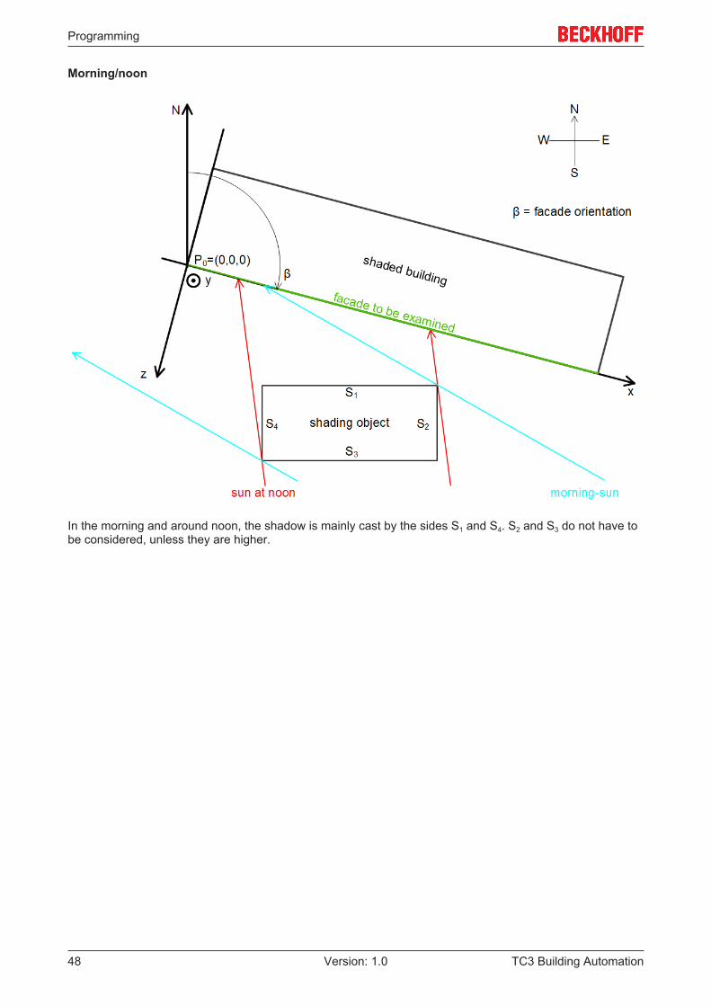
Morning/noon
In the morning and around noon, the shadow is mainly cast by the sides S1 and S4. S2 and S3 do not have tobe considered, unless they are higher.
Programming
TC3 Building Automation 49Version: 1.0
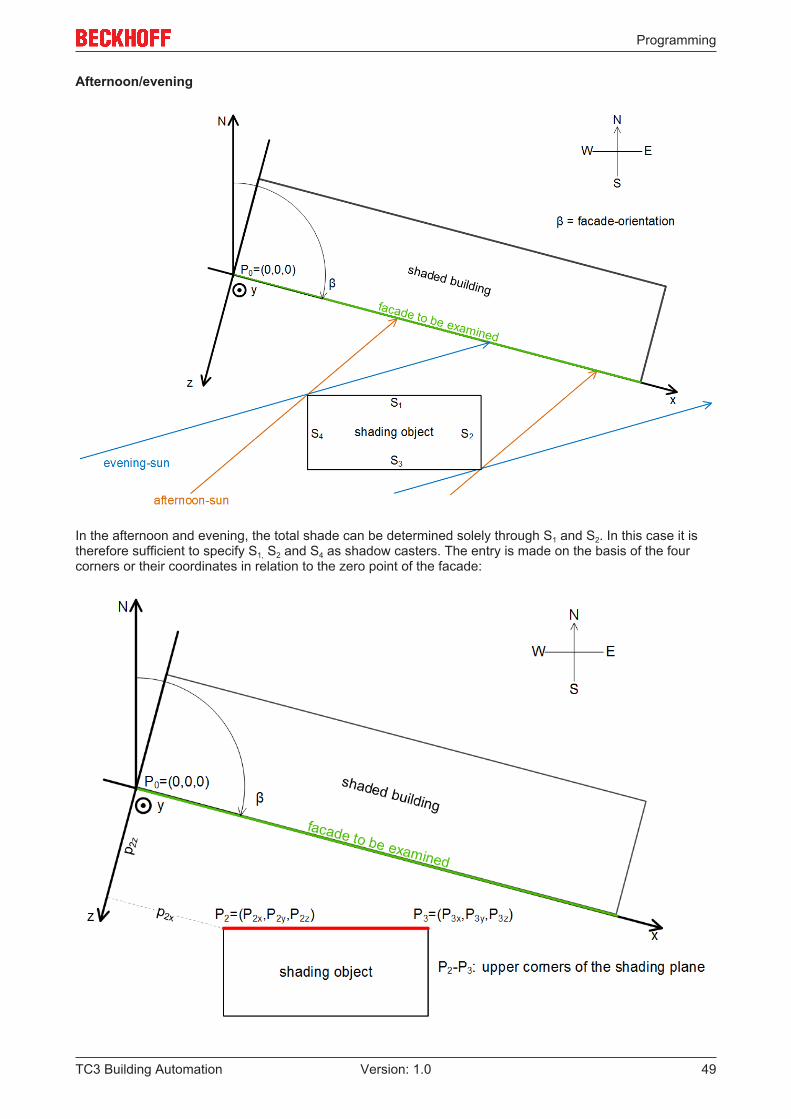
Afternoon/evening
In the afternoon and evening, the total shade can be determined solely through S1 and S2. In this case it istherefore sufficient to specify S1, S2 and S4 as shadow casters. The entry is made on the basis of the fourcorners or their coordinates in relation to the zero point of the facade:
Programming
TC3 Building Automation50 Version: 1.0
In this sketch only the upper points, P2 and P3, are illustrated due to the plan view. The lower point P1 liesunderneath P2 and P4 lies underneath P3.
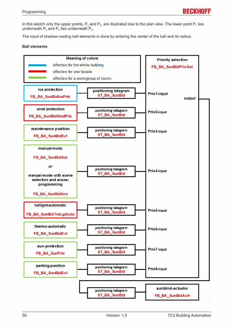
The input of shadow-casting ball elements is done by entering the center of the ball and its radius:
Ball elements
Programming
TC3 Building Automation 51Version: 1.0
A "classification" of the ball element as in the case of the angular building is of course unnecessary, sincethe shadow cast by a ball changes only its direction, but not its size.
Programming
TC3 Building Automation52 Version: 1.0
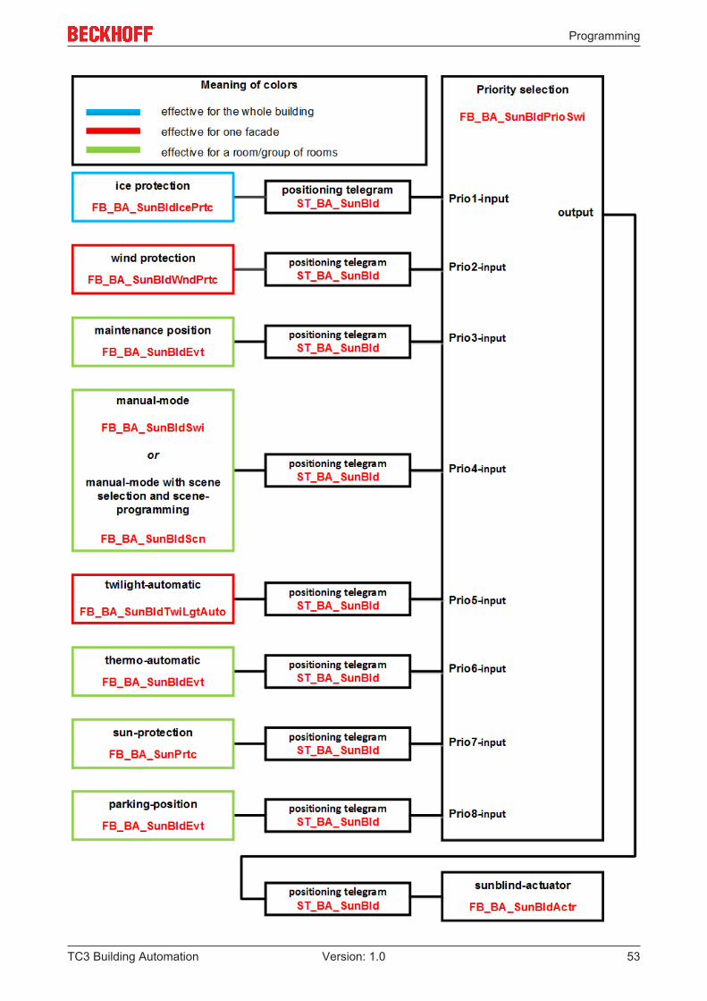
5.1.3.3.3 Overview of automatic sun protection
Programming
TC3 Building Automation 53Version: 1.0
Programming
TC3 Building Automation54 Version: 1.0
5.1.3.3.4 Sun protection: Basic principles and definitions
The direct incidence of daylight is regarded as disturbing by persons in rooms. On the other hand, however,people perceive natural light to be more pleasant in comparison with artificial light. Two options for glareprotection are to be presented here:
• Louvre adjustment• Height adjustment
Louvre adjustment
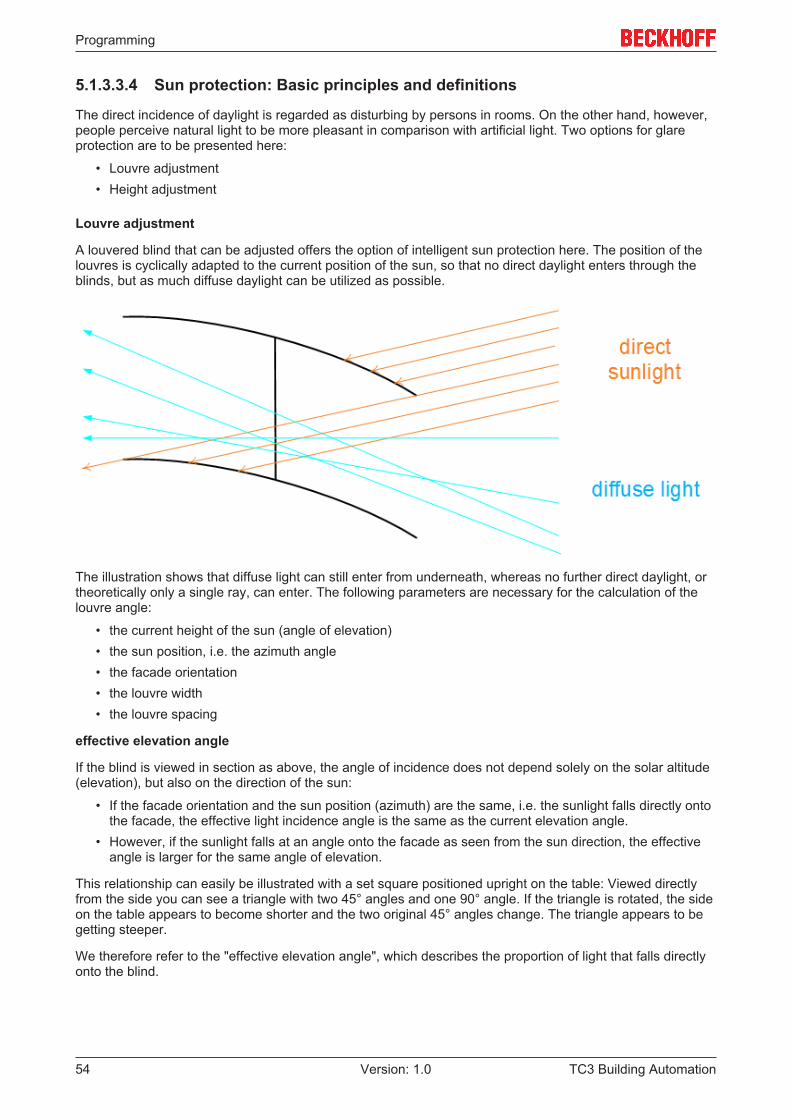
A louvered blind that can be adjusted offers the option of intelligent sun protection here. The position of thelouvres is cyclically adapted to the current position of the sun, so that no direct daylight enters through theblinds, but as much diffuse daylight can be utilized as possible.
The illustration shows that diffuse light can still enter from underneath, whereas no further direct daylight, ortheoretically only a single ray, can enter. The following parameters are necessary for the calculation of thelouvre angle:
• the current height of the sun (angle of elevation)• the sun position, i.e. the azimuth angle• the facade orientation• the louvre width• the louvre spacing
effective elevation angle
If the blind is viewed in section as above, the angle of incidence does not depend solely on the solar altitude(elevation), but also on the direction of the sun:
• If the facade orientation and the sun position (azimuth) are the same, i.e. the sunlight falls directly ontothe facade, the effective light incidence angle is the same as the current elevation angle.
• However, if the sunlight falls at an angle onto the facade as seen from the sun direction, the effectiveangle is larger for the same angle of elevation.
This relationship can easily be illustrated with a set square positioned upright on the table: Viewed directlyfrom the side you can see a triangle with two 45° angles and one 90° angle. If the triangle is rotated, the sideon the table appears to become shorter and the two original 45° angles change. The triangle appears to begetting steeper.
We therefore refer to the "effective elevation angle", which describes the proportion of light that falls directlyonto the blind.
Programming
TC3 Building Automation 55Version: 1.0
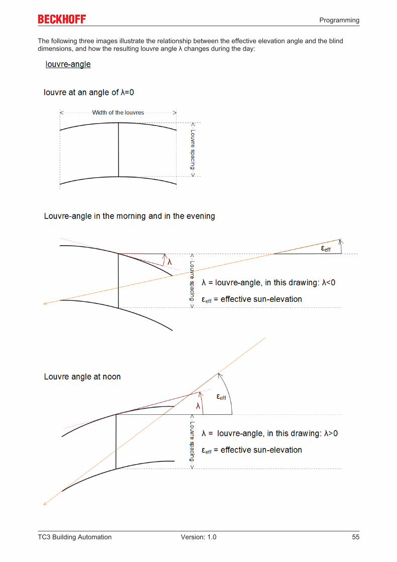
The following three images illustrate the relationship between the effective elevation angle and the blinddimensions, and how the resulting louvre angle λ changes during the day:
Programming
TC3 Building Automation56 Version: 1.0
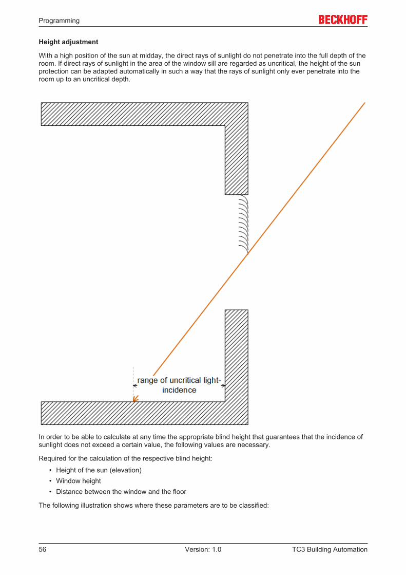
Height adjustment
With a high position of the sun at midday, the direct rays of sunlight do not penetrate into the full depth of theroom. If direct rays of sunlight in the area of the window sill are regarded as uncritical, the height of the sunprotection can be adapted automatically in such a way that the rays of sunlight only ever penetrate into theroom up to an uncritical depth.
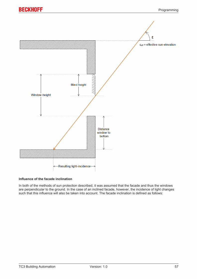
In order to be able to calculate at any time the appropriate blind height that guarantees that the incidence ofsunlight does not exceed a certain value, the following values are necessary.
Required for the calculation of the respective blind height:
• Height of the sun (elevation)• Window height• Distance between the window and the floor
The following illustration shows where these parameters are to be classified:
Programming
TC3 Building Automation 57Version: 1.0
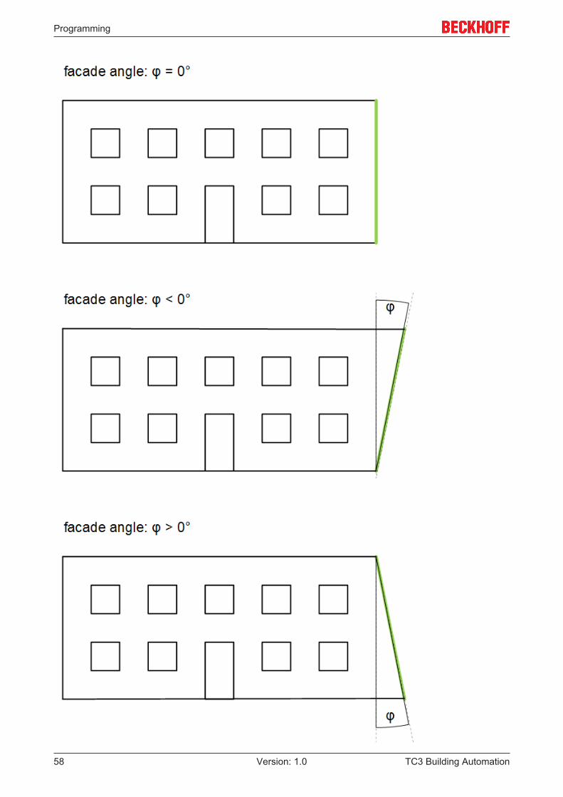
Influence of the facade inclination
In both of the methods of sun protection described, it was assumed that the facade and thus the windowsare perpendicular to the ground. In the case of an inclined facade, however, the incidence of light changessuch that this influence will also be taken into account. The facade inclination is defined as follows:
Programming
TC3 Building Automation58 Version: 1.0
Programming
TC3 Building Automation 59Version: 1.0
5.1.3.3.5 List of shading elements
The data of all shading objects (building components, trees, etc.) per facade are stored in a field of structureelements of type ST_BA_ShdObj [} 182] within the program.
The shading correction FB_BA_ShdCorr [} 83] reads the information from this list. The management functionblock FB_BA_ShdObjEntry [} 86] reads and writes it as input/output variable.It is therefore advisable to declare this list globally:VAR_GLOBAL arrShdObj : ARRAY[1..gBA_cMaxShdObj] OF ST_BA_ShdObj;END_VAR
The variable gBA_cMaxShdObj represents the upper limit of the available elements and is defined as aglobal constant within the program library:VAR_GLOBAL CONSTANT gBA_cMaxShdObj : INT := 20;END_VAR
5.1.3.3.6 List of facade elements
The data of all windows (facade elements) per facade are saved within the program in a field of structureelements of the type ST_BA_FcdElem [} 181].
The management function block FB_BA_FcdElemEntry [} 63] and the shading correction FB_BA_ShdCorr[} 83] read and write to this list (the latter sets the shading information); they access this field as input/output variables.It is therefore advisable to declare this list globally:VAR_GLOBAL arrFcdElem : ARRAY[1..uiMaxRowFcd, 1..uiMaxColumnFcd] OF ST_BA_FcdElem;END_VAR
The variables uiMaxColumnFcd and uiMaxRowFcd define the upper limit of the available elements and aredeclared as global constants within the program library:VAR_GLOBAL CONSTANT uiMaxRowFcd : UINT :=10; uiMaxColumnFcd : UINT :=20;END_VAR
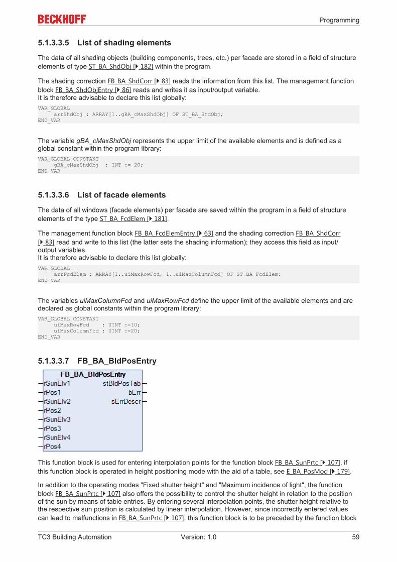
5.1.3.3.7 FB_BA_BldPosEntry
This function block is used for entering interpolation points for the function block FB_BA_SunPrtc [} 107], ifthis function block is operated in height positioning mode with the aid of a table, see E_BA_PosMod [} 179].
In addition to the operating modes "Fixed shutter height" and "Maximum incidence of light", the functionblock FB_BA_SunPrtc [} 107] also offers the possibility to control the shutter height in relation to the positionof the sun by means of table entries. By entering several interpolation points, the shutter height relative tothe respective sun position is calculated by linear interpolation. However, since incorrectly entered valuescan lead to malfunctions in FB_BA_SunPrtc [} 107], this function block is to be preceded by the function block
Programming
TC3 Building Automation60 Version: 1.0
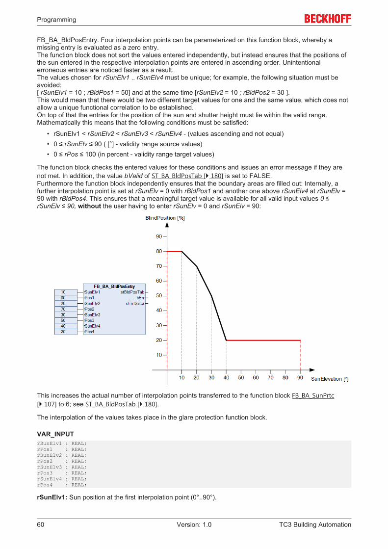
FB_BA_BldPosEntry. Four interpolation points can be parameterized on this function block, whereby amissing entry is evaluated as a zero entry.The function block does not sort the values entered independently, but instead ensures that the positions ofthe sun entered in the respective interpolation points are entered in ascending order. Unintentionalerroneous entries are noticed faster as a result.The values chosen for rSunElv1 .. rSunElv4 must be unique; for example, the following situation must beavoided: [ rSunElv1 = 10 ; rBldPos1 = 50] and at the same time [rSunElv2 = 10 ; rBldPos2 = 30 ].This would mean that there would be two different target values for one and the same value, which does notallow a unique functional correlation to be established.On top of that the entries for the position of the sun and shutter height must lie within the valid range.Mathematically this means that the following conditions must be satisfied:
• rSunElv1 < rSunElv2 < rSunElv3 < rSunElv4 - (values ascending and not equal)• 0 ≤ rSunElv ≤ 90 ( [°] - validity range source values)• 0 ≤ rPos ≤ 100 (in percent - validity range target values)
The function block checks the entered values for these conditions and issues an error message if they arenot met. In addition, the value bValid of ST_BA_BldPosTab [} 180] is set to FALSE.Furthermore the function block independently ensures that the boundary areas are filled out: Internally, afurther interpolation point is set at rSunElv = 0 with rBldPos1 and another one above rSunElv4 at rSunElv =90 with rBldPos4. This ensures that a meaningful target value is available for all valid input values 0 ≤rSunElv ≤ 90, without the user having to enter rSunElv = 0 and rSunElv = 90:
This increases the actual number of interpolation points transferred to the function block FB_BA_SunPrtc[} 107] to 6; see ST_BA_BldPosTab [} 180].
The interpolation of the values takes place in the glare protection function block.
VAR_INPUTrSunElv1 : REAL;rPos1 : REAL;rSunElv2 : REAL;rPos2 : REAL;rSunElv3 : REAL;rPos3 : REAL;rSunElv4 : REAL;rPos4 : REAL;
rSunElv1: Sun position at the first interpolation point (0°..90°).
Programming
TC3 Building Automation 61Version: 1.0
rBldPos1: Blind position (degree of closure) at the first interpolation point (0%..100%).
rSunElv2: Sun position at the second interpolation point (0°..90°).
rBldPos2: Blind position (degree of closure) at the second interpolation point (0%..100%).
rSunElv3: Sun position at the third interpolation point (0°..90°).
rBldPos3: Blind position (degree of closure) at the third interpolation point (0%..100%).
rSunElv4: Sun position at the fourth interpolation point (0°..90°).
rBldPos4: Blind position (degree of closure) at the fourth interpolation point (0%..100%).
VAR_OUTPUTstBldPosTab : ST_BA_BldPosTab;bErr : BOOL;sErrDescr : T_MAXSTRING;
stBldPosTab: Transfer structure of the interpolation points, see ST_BA_BldPosTab [} 180].
bErr: This output is switched to TRUE if the parameters entered are erroneous.
sErrDescr: Contains the error description.
Error description01: Error: The x-values (elevation values) in the table are either not listed in ascending order, or they areduplicated.02: Error: An elevation value that was entered is outside the valid range of 0°..90°.03: Error: An position value that was entered is outside the valid range of 0°...100%.
Requirements
Development environment required library Necessary functionTwinCAT3.1 4022.22 Tc3 Building Automation from
V1.1.0.0TF8040 | TwinCAT BuildingAutomation from V3.1.11.0
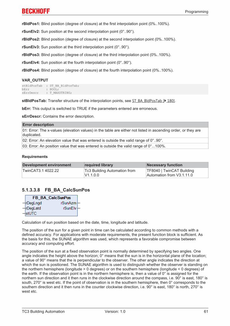
5.1.3.3.8 FB_BA_CalcSunPos
Calculation of sun position based on the date, time, longitude and latitude.
The position of the sun for a given point in time can be calculated according to common methods with adefined accuracy. For applications with moderate requirements, the present function block is sufficient. Asthe basis for this, the SUNAE algorithm was used, which represents a favorable compromise betweenaccuracy and computing effort.
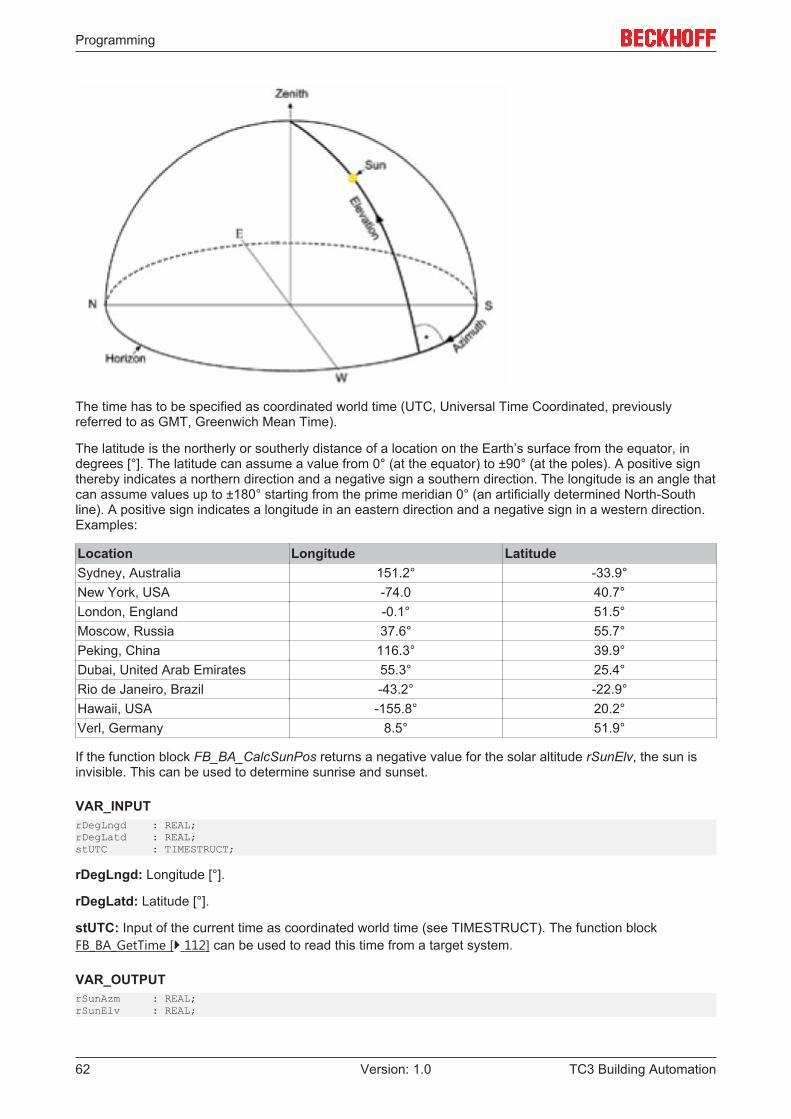
The position of the sun at a fixed observation point is normally determined by specifying two angles. Oneangle indicates the height above the horizon; 0° means that the sun is in the horizontal plane of the location;a value of 90° means that the is perpendicular to the observer. The other angle indicates the direction atwhich the sun is positioned. The SUNAE algorithm is used to distinguish whether the observer is standing onthe northern hemisphere (longitude > 0 degrees) or on the southern hemisphere (longitude < 0 degrees) ofthe earth. If the observation point is in the northern hemisphere is, then a value of 0° is assigned for thenorthern sun direction and it then runs in the clockwise direction around the compass, i.e. 90° is east, 180° issouth, 270° is west etc. If the point of observation is in the southern hemisphere, then 0° corresponds to thesouthern direction and it then runs in the counter clockwise direction, i.e. 90° is east, 180° is north, 270° iswest etc.
Programming
TC3 Building Automation62 Version: 1.0
The time has to be specified as coordinated world time (UTC, Universal Time Coordinated, previouslyreferred to as GMT, Greenwich Mean Time).
The latitude is the northerly or southerly distance of a location on the Earth’s surface from the equator, indegrees [°]. The latitude can assume a value from 0° (at the equator) to ±90° (at the poles). A positive signthereby indicates a northern direction and a negative sign a southern direction. The longitude is an angle thatcan assume values up to ±180° starting from the prime meridian 0° (an artificially determined North-Southline). A positive sign indicates a longitude in an eastern direction and a negative sign in a western direction.Examples:
Location Longitude LatitudeSydney, Australia 151.2° -33.9°New York, USA -74.0 40.7°London, England -0.1° 51.5°Moscow, Russia 37.6° 55.7°Peking, China 116.3° 39.9°Dubai, United Arab Emirates 55.3° 25.4°Rio de Janeiro, Brazil -43.2° -22.9°Hawaii, USA -155.8° 20.2°Verl, Germany 8.5° 51.9°
If the function block FB_BA_CalcSunPos returns a negative value for the solar altitude rSunElv, the sun isinvisible. This can be used to determine sunrise and sunset.
VAR_INPUTrDegLngd : REAL;rDegLatd : REAL;stUTC : TIMESTRUCT;
rDegLngd: Longitude [°].
rDegLatd: Latitude [°].
stUTC: Input of the current time as coordinated world time (see TIMESTRUCT). The function blockFB_BA_GetTime [} 112] can be used to read this time from a target system.
VAR_OUTPUTrSunAzm : REAL;rSunElv : REAL;
Programming
TC3 Building Automation 63Version: 1.0
rSunAzm: Direction of the sun (northern hemisphere: 0° north ... 90° east ... 180° south ... 270° west ... /southern hemisphere: 0° south ... 90° east ... 180° north ... 270° west ...).
rSunElv: Height of the sun (0° horizontal - 90° vertical).
Requirements
Development environment required library Necessary functionTwinCAT3.1 4022.22 Tc3 Building Automation from
V1.1.0.0TF8040 | TwinCAT BuildingAutomation from V3.1.11.0
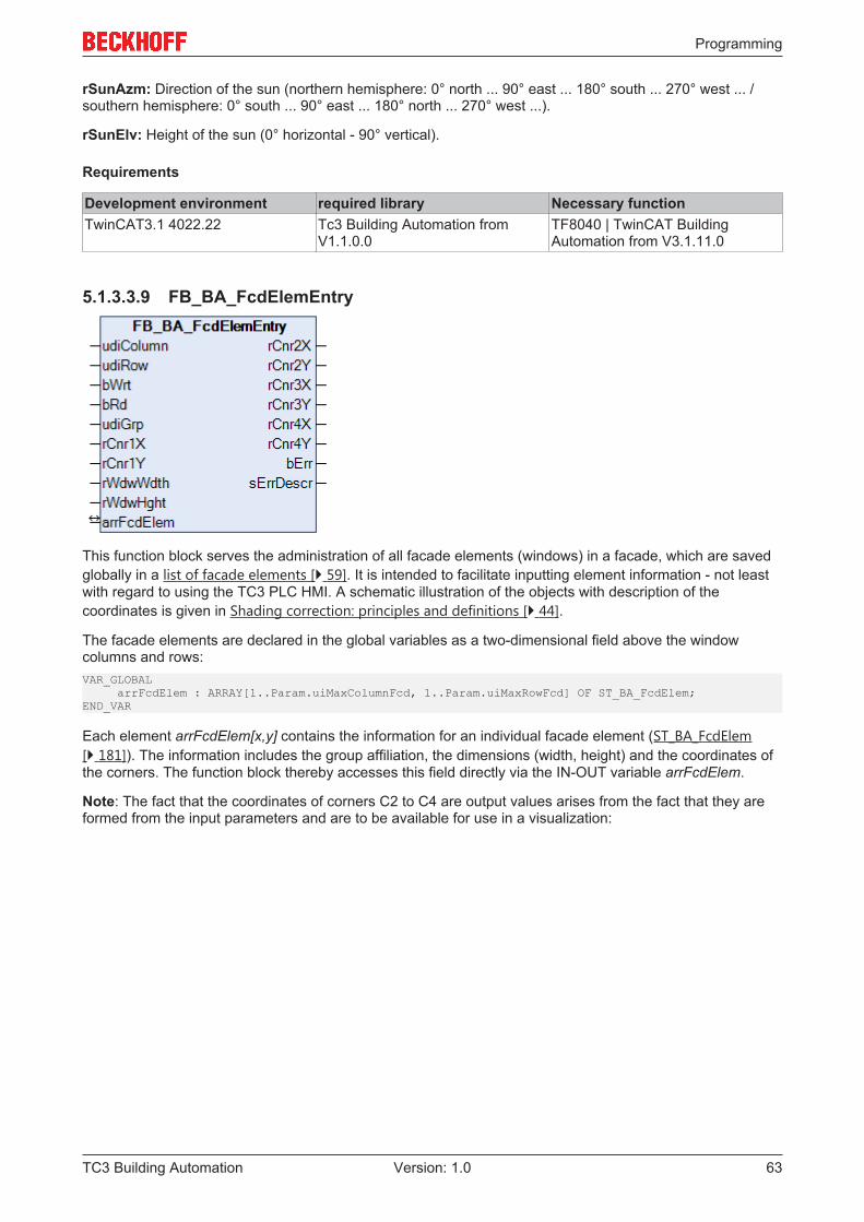
5.1.3.3.9 FB_BA_FcdElemEntry
This function block serves the administration of all facade elements (windows) in a facade, which are savedglobally in a list of facade elements [} 59]. It is intended to facilitate inputting element information - not leastwith regard to using the TC3 PLC HMI. A schematic illustration of the objects with description of thecoordinates is given in Shading correction: principles and definitions [} 44].
The facade elements are declared in the global variables as a two-dimensional field above the windowcolumns and rows:VAR_GLOBAL arrFcdElem : ARRAY[1..Param.uiMaxColumnFcd, 1..Param.uiMaxRowFcd] OF ST_BA_FcdElem;END_VAR
Each element arrFcdElem[x,y] contains the information for an individual facade element (ST_BA_FcdElem[} 181]). The information includes the group affiliation, the dimensions (width, height) and the coordinates ofthe corners. The function block thereby accesses this field directly via the IN-OUT variable arrFcdElem.
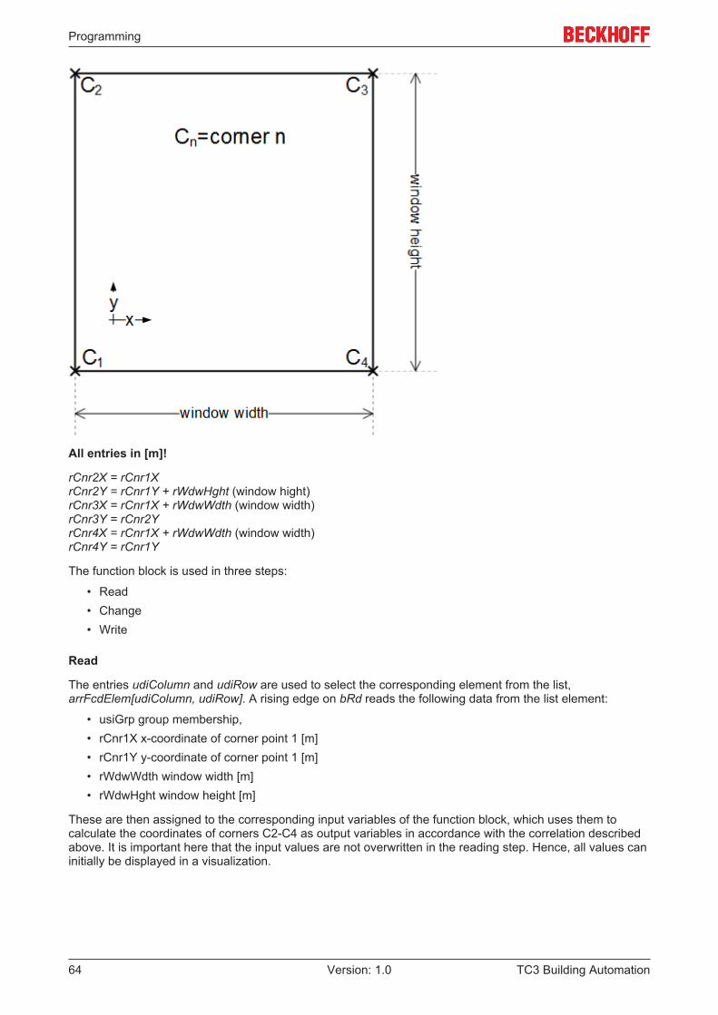
Note: The fact that the coordinates of corners C2 to C4 are output values arises from the fact that they areformed from the input parameters and are to be available for use in a visualization:
Programming
TC3 Building Automation64 Version: 1.0
All entries in [m]!
rCnr2X = rCnr1XrCnr2Y = rCnr1Y + rWdwHght (window hight)rCnr3X = rCnr1X + rWdwWdth (window width)rCnr3Y = rCnr2YrCnr4X = rCnr1X + rWdwWdth (window width)rCnr4Y = rCnr1Y
The function block is used in three steps:
• Read• Change• Write
Read
The entries udiColumn and udiRow are used to select the corresponding element from the list,arrFcdElem[udiColumn, udiRow]. A rising edge on bRd reads the following data from the list element:
• usiGrp group membership,• rCnr1X x-coordinate of corner point 1 [m]• rCnr1Y y-coordinate of corner point 1 [m]• rWdwWdth window width [m]• rWdwHght window height [m]
These are then assigned to the corresponding input variables of the function block, which uses them tocalculate the coordinates of corners C2-C4 as output variables in accordance with the correlation describedabove. It is important here that the input values are not overwritten in the reading step. Hence, all values caninitially be displayed in a visualization.
Programming
TC3 Building Automation 65Version: 1.0
Change
In a next program step the listed input values can then be changed. The values entered are constantlychecked for plausibility. The output bErr indicates whether the values are valid (bErr=FALSE). If the valuesare invalid, a corresponding error message is issued at output sErrDescr. See also "Error (bErr=TRUE)"below.
Write
The parameterized data are written to the list element with the index nId upon a rising edge on bWrt,regardless of whether they represent valid values or not. The element structure ST_BA_FcdElem [} 181]therefore also contains a plausibility bit bVld, which forwards precisely this information to the function blockFB_BA_ShdCorr [} 83] to prevent miscalculations.
This approach is to be regarded only as a proposal. It is naturally also possible to parameterize the functionblock quite normally in one step and to write the values entered to the corresponding list element with arising edge on bWrt.
Error (bErr=TRUE)
The function block FB_BA_ShdCorr [} 83], which judges whether all windows in a group are shaded, will onlyperform its task if all windows in the examined group have valid entries.This means:
• usiGrp must be greater than 0• rCnr1X must greater than or equal to 0.0• rCnr1Y must greater than or equal to 0.0• rWdwWdth must be greater than 0• rWdwHght must be greater than 0
If one of these criteria is not met, it is interpreted as incorrect input, and the error output bErr is set at thefunction block output of FB_BA_FcdElemEntry. Within the window element ST_BA_FcdElem [} 181], theplausibility bit bVld is set to FALSE.If on the other hand all entries of a facade element are zero, it is regarded as a valid, deliberately omittedfacade element:
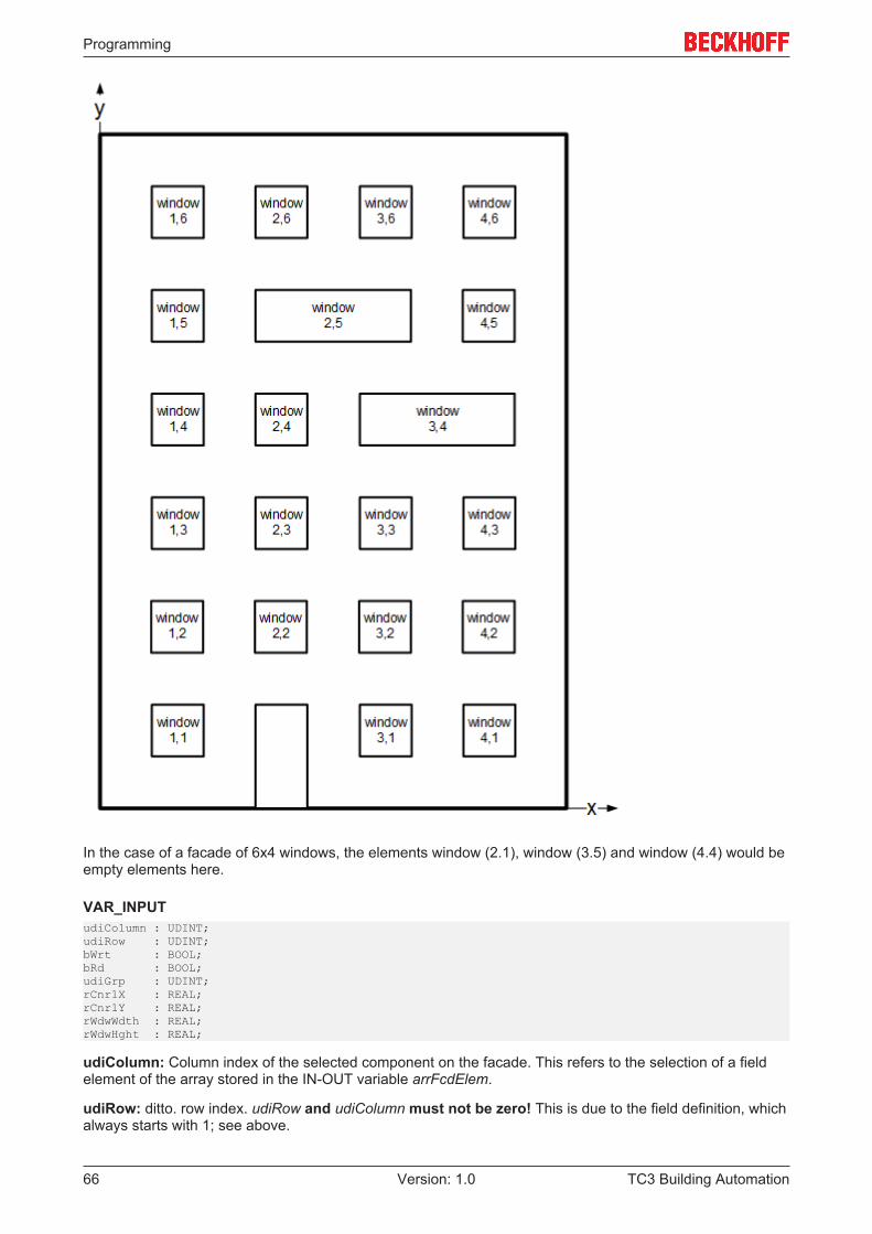
Programming
TC3 Building Automation66 Version: 1.0
In the case of a facade of 6x4 windows, the elements window (2.1), window (3.5) and window (4.4) would beempty elements here.
VAR_INPUTudiColumn : UDINT;udiRow : UDINT;bWrt : BOOL;bRd : BOOL;udiGrp : UDINT;rCnr1X : REAL;rCnr1Y : REAL;rWdwWdth : REAL;rWdwHght : REAL;
udiColumn: Column index of the selected component on the facade. This refers to the selection of a fieldelement of the array stored in the IN-OUT variable arrFcdElem.
udiRow: ditto. row index. udiRow and udiColumn must not be zero! This is due to the field definition, whichalways starts with 1; see above.
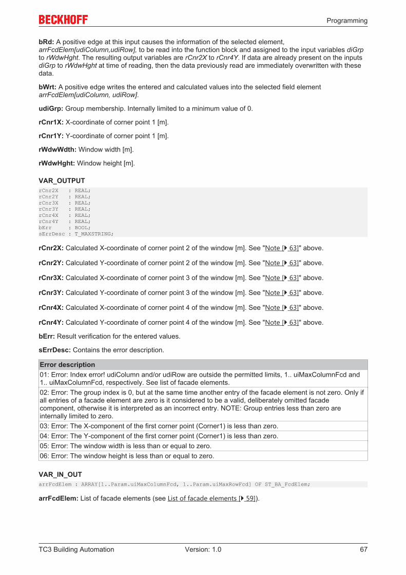
Programming
TC3 Building Automation 67Version: 1.0
bRd: A positive edge at this input causes the information of the selected element,arrFcdElem[udiColumn,udiRow], to be read into the function block and assigned to the input variables diGrpto rWdwHght. The resulting output variables are rCnr2X to rCnr4Y. If data are already present on the inputsdiGrp to rWdwHght at time of reading, then the data previously read are immediately overwritten with thesedata.
bWrt: A positive edge writes the entered and calculated values into the selected field elementarrFcdElem[udiColumn, udiRow].
udiGrp: Group membership. Internally limited to a minimum value of 0.
rCnr1X: X-coordinate of corner point 1 [m].
rCnr1Y: Y-coordinate of corner point 1 [m].
rWdwWdth: Window width [m].
rWdwHght: Window height [m].
VAR_OUTPUTrCnr2X : REAL;rCnr2Y : REAL;rCnr3X : REAL;rCnr3Y : REAL;rCnr4X : REAL;rCnr4Y : REAL;bErr : BOOL;sErrDesc : T_MAXSTRING;
rCnr2X: Calculated X-coordinate of corner point 2 of the window [m]. See "Note [} 63]" above.
rCnr2Y: Calculated Y-coordinate of corner point 2 of the window [m]. See "Note [} 63]" above.
rCnr3X: Calculated X-coordinate of corner point 3 of the window [m]. See "Note [} 63]" above.
rCnr3Y: Calculated Y-coordinate of corner point 3 of the window [m]. See "Note [} 63]" above.
rCnr4X: Calculated X-coordinate of corner point 4 of the window [m]. See "Note [} 63]" above.
rCnr4Y: Calculated Y-coordinate of corner point 4 of the window [m]. See "Note [} 63]" above.
bErr: Result verification for the entered values.
sErrDesc: Contains the error description.
Error description01: Error: Index error! udiColumn and/or udiRow are outside the permitted limits, 1.. uiMaxColumnFcd and1.. uiMaxColumnFcd, respectively. See list of facade elements.02: Error: The group index is 0, but at the same time another entry of the facade element is not zero. Only ifall entries of a facade element are zero is it considered to be a valid, deliberately omitted facadecomponent, otherwise it is interpreted as an incorrect entry. NOTE: Group entries less than zero areinternally limited to zero.03: Error: The X-component of the first corner point (Corner1) is less than zero.04: Error: The Y-component of the first corner point (Corner1) is less than zero.05: Error: The window width is less than or equal to zero.06: Error: The window height is less than or equal to zero.
VAR_IN_OUTarrFcdElem : ARRAY[1..Param.uiMaxColumnFcd, 1..Param.uiMaxRowFcd] OF ST_BA_FcdElem;
arrFcdElem: List of facade elements (see List of facade elements [} 59]).
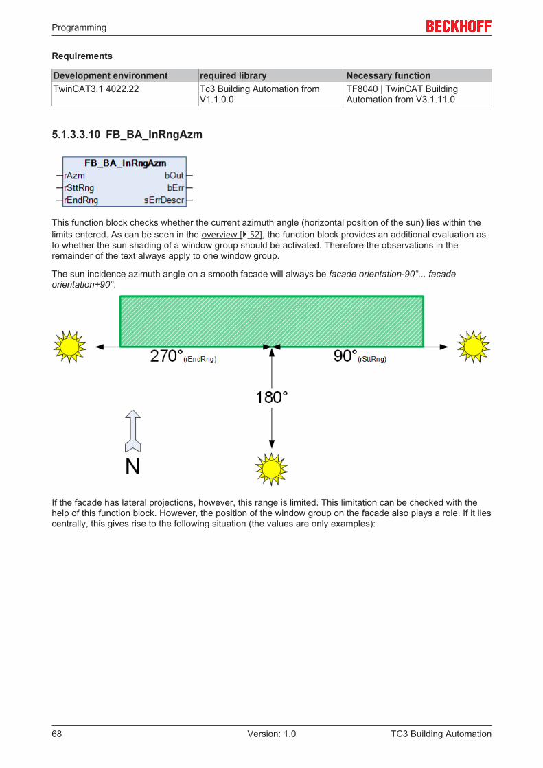
Programming
TC3 Building Automation68 Version: 1.0
Requirements
Development environment required library Necessary functionTwinCAT3.1 4022.22 Tc3 Building Automation from
V1.1.0.0TF8040 | TwinCAT BuildingAutomation from V3.1.11.0
5.1.3.3.10 FB_BA_InRngAzm
This function block checks whether the current azimuth angle (horizontal position of the sun) lies within thelimits entered. As can be seen in the overview [} 52], the function block provides an additional evaluation asto whether the sun shading of a window group should be activated. Therefore the observations in theremainder of the text always apply to one window group.
The sun incidence azimuth angle on a smooth facade will always be facade orientation-90°... facadeorientation+90°.
If the facade has lateral projections, however, this range is limited. This limitation can be checked with thehelp of this function block. However, the position of the window group on the facade also plays a role. If it liescentrally, this gives rise to the following situation (the values are only examples):
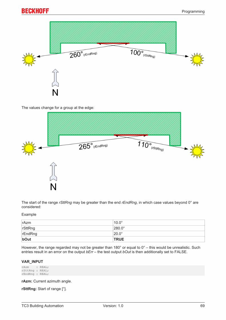
Programming
TC3 Building Automation 69Version: 1.0
The values change for a group at the edge:
The start of the range rSttRng may be greater than the end rEndRng, in which case values beyond 0° areconsidered:
Example
rAzm 10.0°rSttRng 280.0°rEndRng 20.0°bOut TRUE
However, the range regarded may not be greater than 180° or equal to 0° – this would be unrealistic. Suchentries result in an error on the output bErr – the test output bOut is then additionally set to FALSE.
VAR_INPUTrAzm : REAL;rSttRng : REAL;rEndRng : REAL;
rAzm: Current azimuth angle.
rSttRng: Start of range [°].
Programming
TC3 Building Automation70 Version: 1.0
rEndRng: End of range [°].
VAR_OUTPUTbOut : BOOL;bErr : BOOL;sErrDescr : T_MAXSTRING;
bOut: The facade element is in the sun if the output is TRUE.
bErr: This output is switched to TRUE if the parameters entered are erroneous.
sErrDescr: Contains the error description.
Error description01: Error: rSttRng or rEndRng less than 0° or greater than 360°.02: Error: The difference between rSttRng and rEndRng is greater than 180°. This range is too large foranalyzing the insolation on a facade.
Requirements
Development environment required library Necessary functionTwinCAT3.1 4022.22 Tc3 Building Automation from
V1.1.0.0TF8040 | TwinCAT BuildingAutomation from V3.1.11.0
5.1.3.3.11 FB_BA_InRngElv
This function block checks whether the current angle of elevation (vertical position of the sun) lies within thelimits entered. As can be seen in the overview [} 52], the function block provides an additionally evaluationas to whether the sun shading of a window group should be activated. Therefore the observations in theremainder of the text always apply to one window group.
A normal vertical facade is irradiated by the sun at an angle of elevation of 0° to maximally 90°.
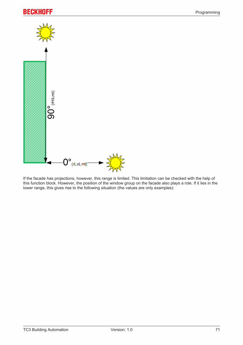
Programming
TC3 Building Automation 71Version: 1.0
If the facade has projections, however, this range is limited. This limitation can be checked with the help ofthis function block. However, the position of the window group on the facade also plays a role. If it lies in thelower range, this gives rise to the following situation (the values are only examples):
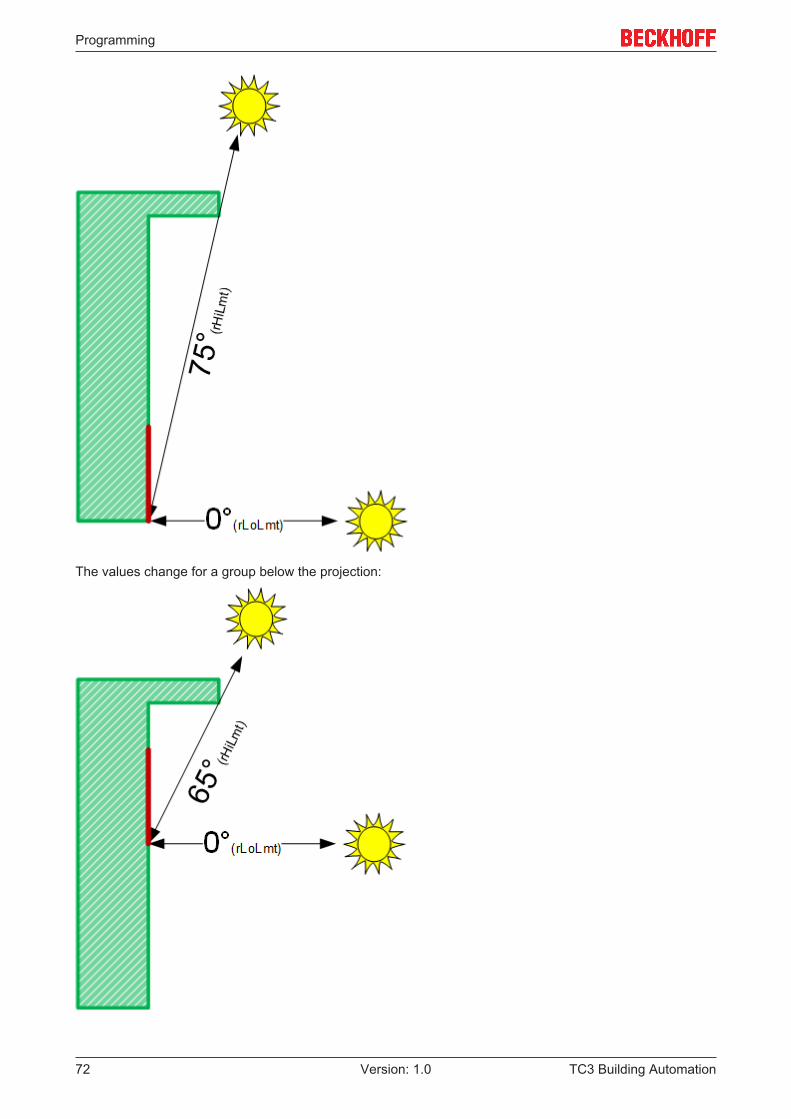
Programming
TC3 Building Automation72 Version: 1.0
The values change for a group below the projection:
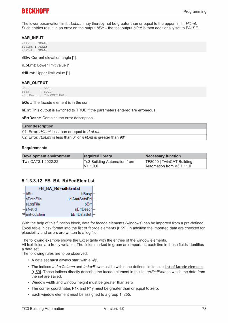
Programming
TC3 Building Automation 73Version: 1.0
The lower observation limit, rLoLmt, may thereby not be greater than or equal to the upper limit, rHiLmt.Such entries result in an error on the output bErr – the test output bOut is then additionally set to FALSE.
VAR_INPUTrElv : REAL;rLoLmt : REAL;rHiLmt : REAL;
rElv: Current elevation angle [°].
rLoLmt: Lower limit value [°].
rHiLmt: Upper limit value [°].
VAR_OUTPUTbOut : BOOL;bErr : BOOL;sErrDescr : T_MAXSTRING;
bOut: The facade element is in the sun
bErr: This output is switched to TRUE if the parameters entered are erroneous.
sErrDescr: Contains the error description.
Error description01: Error: rHiLmt less than or equal to rLoLmt.02: Error: rLoLmt is less than 0° or rHiLmt is greater than 90°.
Requirements
Development environment required library Necessary functionTwinCAT3.1 4022.22 Tc3 Building Automation from
V1.1.0.0TF8040 | TwinCAT BuildingAutomation from V3.1.11.0
5.1.3.3.12 FB_BA_RdFcdElemLst
With the help of this function block, data for facade elements (windows) can be imported from a pre-definedExcel table in csv format into the list of facade elements [} 59]. In addition the imported data are checked forplausibility and errors are written to a log file.
The following example shows the Excel table with the entries of the window elements.All text fields are freely writable. The fields marked in green are important; each line in these fields identifiesa data set.The following rules are to be observed:
• A data set must always start with a '@'.
• The indices IndexColumn and IndexRow must lie within the defined limits, see List of facade elements[} 59]. These indices directly describe the facade element in the list arrFcdElem to which the data fromthe set are saved.
• Window width and window height must be greater than zero• The corner coordinates P1x and P1y must be greater than or equal to zero.• Each window element must be assigned to a group 1..255.
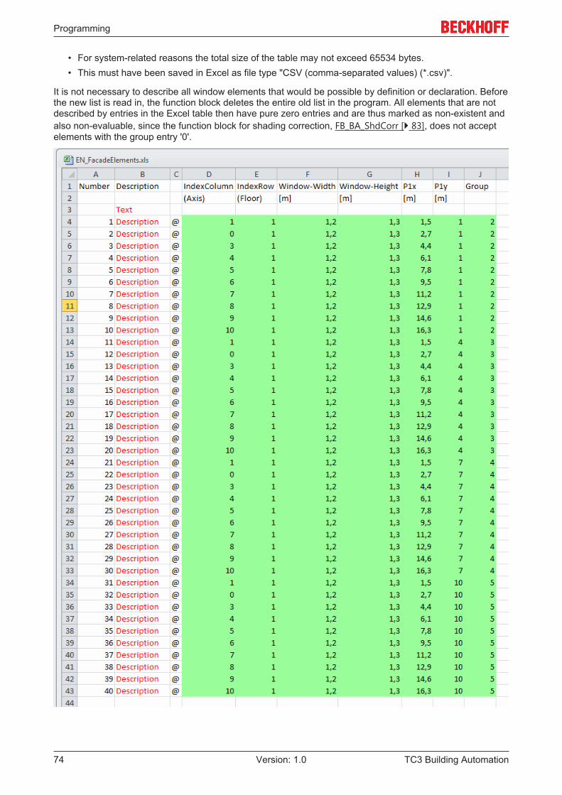
Programming
TC3 Building Automation74 Version: 1.0
• For system-related reasons the total size of the table may not exceed 65534 bytes.• This must have been saved in Excel as file type "CSV (comma-separated values) (*.csv)".
It is not necessary to describe all window elements that would be possible by definition or declaration. Beforethe new list is read in, the function block deletes the entire old list in the program. All elements that are notdescribed by entries in the Excel table then have pure zero entries and are thus marked as non-existent andalso non-evaluable, since the function block for shading correction, FB_BA_ShdCorr [} 83], does not acceptelements with the group entry '0'.
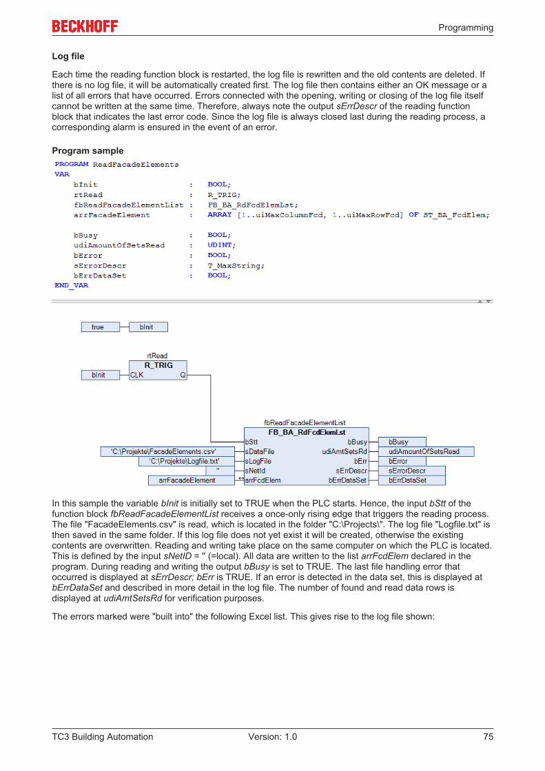
Programming
TC3 Building Automation 75Version: 1.0
Log file
Each time the reading function block is restarted, the log file is rewritten and the old contents are deleted. Ifthere is no log file, it will be automatically created first. The log file then contains either an OK message or alist of all errors that have occurred. Errors connected with the opening, writing or closing of the log file itselfcannot be written at the same time. Therefore, always note the output sErrDescr of the reading functionblock that indicates the last error code. Since the log file is always closed last during the reading process, acorresponding alarm is ensured in the event of an error.
Program sample
In this sample the variable bInit is initially set to TRUE when the PLC starts. Hence, the input bStt of thefunction block fbReadFacadeElementList receives a once-only rising edge that triggers the reading process.The file "FacadeElements.csv" is read, which is located in the folder "C:\Projects\". The log file "Logfile.txt" isthen saved in the same folder. If this log file does not yet exist it will be created, otherwise the existingcontents are overwritten. Reading and writing take place on the same computer on which the PLC is located.This is defined by the input sNetID = '' (=local). All data are written to the list arrFcdElem declared in theprogram. During reading and writing the output bBusy is set to TRUE. The last file handling error thatoccurred is displayed at sErrDescr; bErr is TRUE. If an error is detected in the data set, this is displayed atbErrDataSet and described in more detail in the log file. The number of found and read data rows isdisplayed at udiAmtSetsRd for verification purposes.
The errors marked were "built into" the following Excel list. This gives rise to the log file shown:
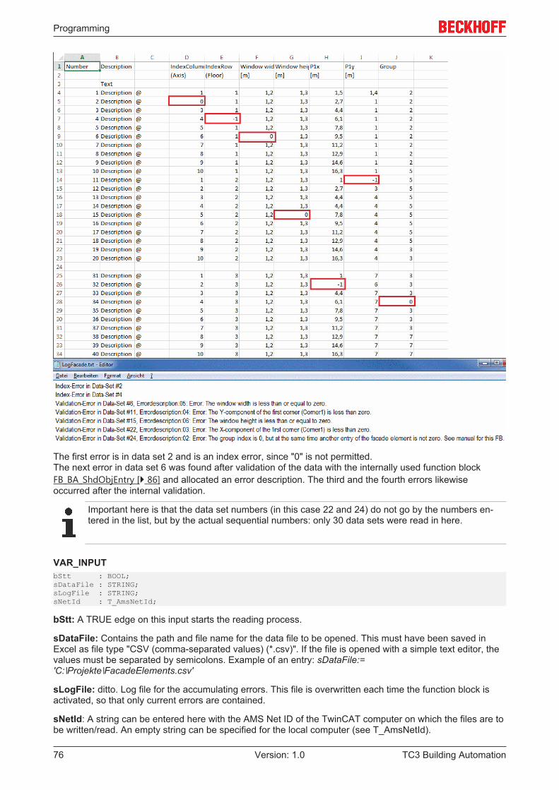
Programming
TC3 Building Automation76 Version: 1.0
The first error is in data set 2 and is an index error, since "0" is not permitted.The next error in data set 6 was found after validation of the data with the internally used function blockFB_BA_ShdObjEntry [} 86] and allocated an error description. The third and the fourth errors likewiseoccurred after the internal validation.
Important here is that the data set numbers (in this case 22 and 24) do not go by the numbers en-tered in the list, but by the actual sequential numbers: only 30 data sets were read in here.
VAR_INPUTbStt : BOOL;sDataFile : STRING;sLogFile : STRING;sNetId : T_AmsNetId;
bStt: A TRUE edge on this input starts the reading process.
sDataFile: Contains the path and file name for the data file to be opened. This must have been saved inExcel as file type "CSV (comma-separated values) (*.csv)". If the file is opened with a simple text editor, thevalues must be separated by semicolons. Example of an entry: sDataFile:='C:∖Projekte∖FacadeElements.csv'
sLogFile: ditto. Log file for the accumulating errors. This file is overwritten each time the function block isactivated, so that only current errors are contained.
sNetId: A string can be entered here with the AMS Net ID of the TwinCAT computer on which the files are tobe written/read. An empty string can be specified for the local computer (see T_AmsNetId).
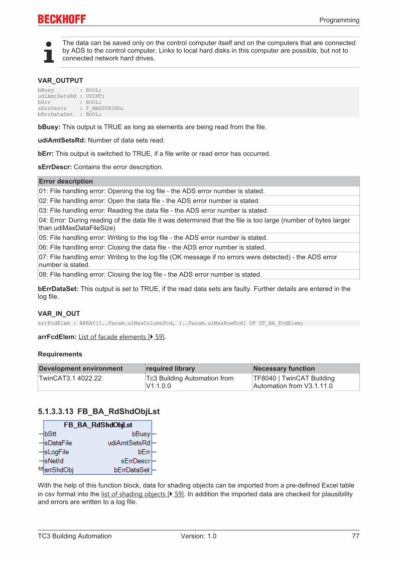
Programming
TC3 Building Automation 77Version: 1.0
The data can be saved only on the control computer itself and on the computers that are connectedby ADS to the control computer. Links to local hard disks in this computer are possible, but not toconnected network hard drives.
VAR_OUTPUTbBusy : BOOL;udiAmtSetsRd : UDINT;bErr : BOOL;sErrDescr : T_MAXSTRING;bErrDataSet : BOOL;
bBusy: This output is TRUE as long as elements are being read from the file.
udiAmtSetsRd: Number of data sets read.
bErr: This output is switched to TRUE, if a file write or read error has occurred.
sErrDescr: Contains the error description.
Error description01: File handling error: Opening the log file - the ADS error number is stated.02: File handling error: Open the data file - the ADS error number is stated.03: File handling error: Reading the data file - the ADS error number is stated.04: Error: During reading of the data file it was determined that the file is too large (number of bytes largerthan udiMaxDataFileSize)05: File handling error: Writing to the log file - the ADS error number is stated.06: File handling error: Closing the data file - the ADS error number is stated.07: File handling error: Writing to the log file (OK message if no errors were detected) - the ADS errornumber is stated.08: File handling error: Closing the log file - the ADS error number is stated.
bErrDataSet: This output is set to TRUE, if the read data sets are faulty. Further details are entered in thelog file.
VAR_IN_OUTarrFcdElem : ARRAY[1..Param.uiMaxColumnFcd, 1..Param.uiMaxRowFcd] OF ST_BA_FcdElem;
arrFcdElem: List of facade elements [} 59].
Requirements
Development environment required library Necessary functionTwinCAT3.1 4022.22 Tc3 Building Automation from
V1.1.0.0TF8040 | TwinCAT BuildingAutomation from V3.1.11.0
5.1.3.3.13 FB_BA_RdShdObjLst
With the help of this function block, data for shading objects can be imported from a pre-defined Excel tablein csv format into the list of shading objects [} 59]. In addition the imported data are checked for plausibilityand errors are written to a log file.
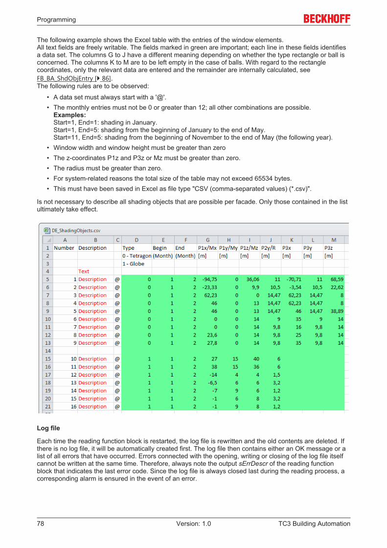
Programming
TC3 Building Automation78 Version: 1.0
The following example shows the Excel table with the entries of the window elements.All text fields are freely writable. The fields marked in green are important; each line in these fields identifiesa data set. The columns G to J have a different meaning depending on whether the type rectangle or ball isconcerned. The columns K to M are to be left empty in the case of balls. With regard to the rectanglecoordinates, only the relevant data are entered and the remainder are internally calculated, seeFB_BA_ShdObjEntry [} 86].The following rules are to be observed:
• A data set must always start with a '@'.• The monthly entries must not be 0 or greater than 12; all other combinations are possible.
Examples:Start=1, End=1: shading in January.Start=1, End=5: shading from the beginning of January to the end of May.Start=11, End=5: shading from the beginning of November to the end of May (the following year).
• Window width and window height must be greater than zero• The z-coordinates P1z and P3z or Mz must be greater than zero.• The radius must be greater than zero.• For system-related reasons the total size of the table may not exceed 65534 bytes.• This must have been saved in Excel as file type "CSV (comma-separated values) (*.csv)".
Is not necessary to describe all shading objects that are possible per facade. Only those contained in the listultimately take effect.
Log file
Each time the reading function block is restarted, the log file is rewritten and the old contents are deleted. Ifthere is no log file, it will be automatically created first. The log file then contains either an OK message or alist of all errors that have occurred. Errors connected with the opening, writing or closing of the log file itselfcannot be written at the same time. Therefore, always note the output sErrDescr of the reading functionblock that indicates the last error code. Since the log file is always closed last during the reading process, acorresponding alarm is ensured in the event of an error.
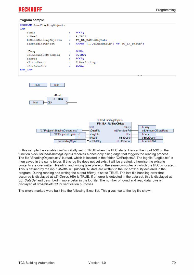
Programming
TC3 Building Automation 79Version: 1.0
Program sample
In this sample the variable bInit is initially set to TRUE when the PLC starts. Hence, the input bStt on thefunction block fbReadShadingObjects receives a once-only rising edge that triggers the reading process.The file "ShadingObjects.csv" is read, which is located in the folder "C:\Projects\". The log file "Logfile.txt" isthen saved in the same folder. If this log file does not yet exist it will be created, otherwise the existingcontents are overwritten. Reading and writing take place on the same computer on which the PLC is located.This is defined by the input sNetID = '' (=local). All data are written to the list arrShdObj declared in theprogram. During reading and writing the output bBusy is set to TRUE. The last file handling error thatoccurred is displayed at sErrDescr; bErr is TRUE. If an error is detected in the data set, this is displayed atbErrDataSet and described in more detail in the log file. The number of found and read data rows isdisplayed at udiAmtSetsRd for verification purposes.
The errors marked were built into the following Excel list. This gives rise to the log file shown:
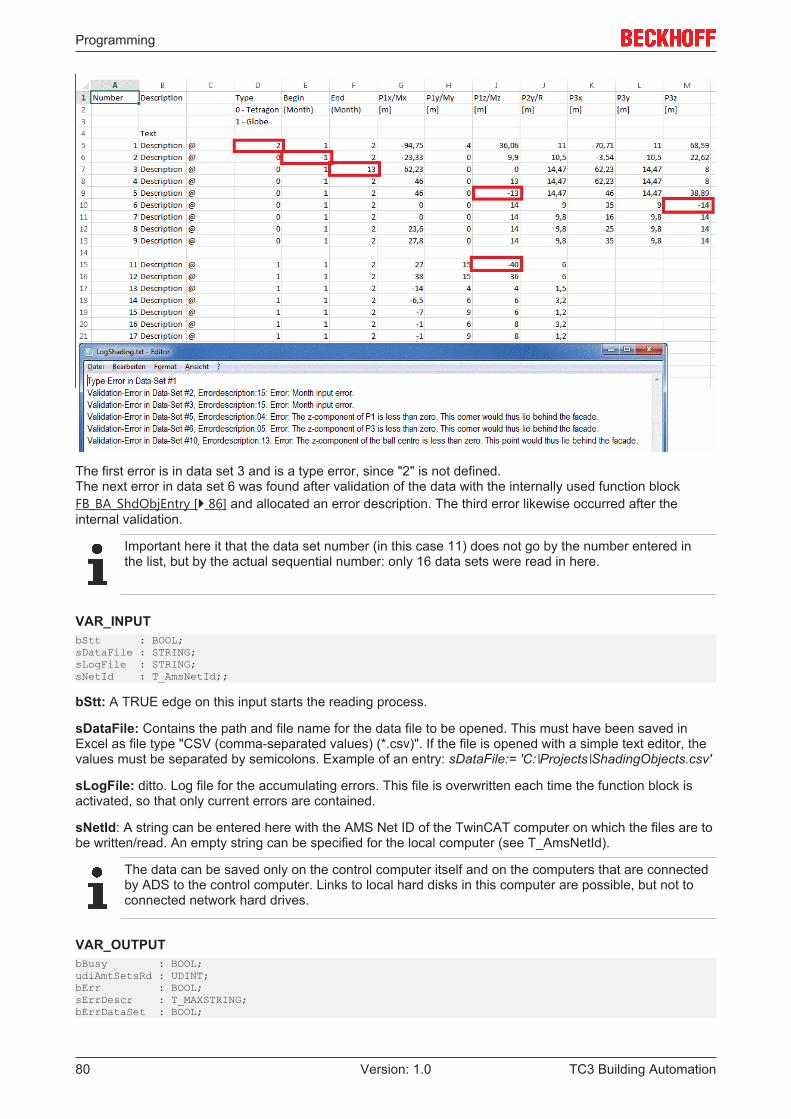
Programming
TC3 Building Automation80 Version: 1.0
The first error is in data set 3 and is a type error, since "2" is not defined.The next error in data set 6 was found after validation of the data with the internally used function blockFB_BA_ShdObjEntry [} 86] and allocated an error description. The third error likewise occurred after theinternal validation.
Important here it that the data set number (in this case 11) does not go by the number entered inthe list, but by the actual sequential number: only 16 data sets were read in here.
VAR_INPUTbStt : BOOL;sDataFile : STRING;sLogFile : STRING;sNetId : T_AmsNetId;;
bStt: A TRUE edge on this input starts the reading process.
sDataFile: Contains the path and file name for the data file to be opened. This must have been saved inExcel as file type "CSV (comma-separated values) (*.csv)". If the file is opened with a simple text editor, thevalues must be separated by semicolons. Example of an entry: sDataFile:= 'C:∖Projects∖ShadingObjects.csv'
sLogFile: ditto. Log file for the accumulating errors. This file is overwritten each time the function block isactivated, so that only current errors are contained.
sNetId: A string can be entered here with the AMS Net ID of the TwinCAT computer on which the files are tobe written/read. An empty string can be specified for the local computer (see T_AmsNetId).
The data can be saved only on the control computer itself and on the computers that are connectedby ADS to the control computer. Links to local hard disks in this computer are possible, but not toconnected network hard drives.
VAR_OUTPUTbBusy : BOOL;udiAmtSetsRd : UDINT;bErr : BOOL;sErrDescr : T_MAXSTRING;bErrDataSet : BOOL;
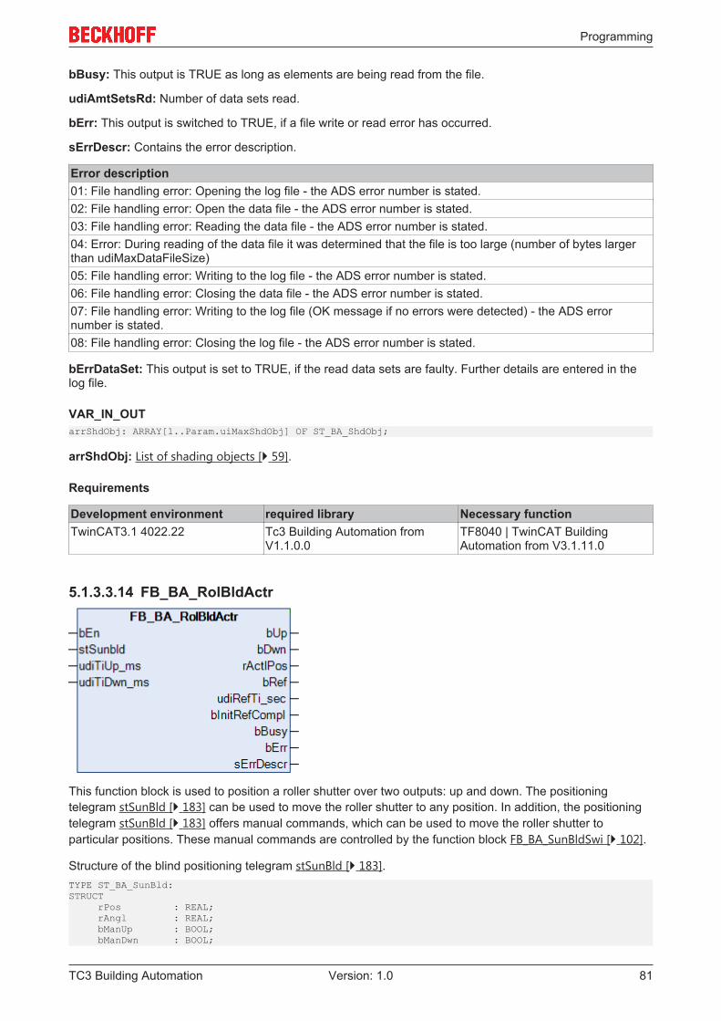
Programming
TC3 Building Automation 81Version: 1.0
bBusy: This output is TRUE as long as elements are being read from the file.
udiAmtSetsRd: Number of data sets read.
bErr: This output is switched to TRUE, if a file write or read error has occurred.
sErrDescr: Contains the error description.
Error description01: File handling error: Opening the log file - the ADS error number is stated.02: File handling error: Open the data file - the ADS error number is stated.03: File handling error: Reading the data file - the ADS error number is stated.04: Error: During reading of the data file it was determined that the file is too large (number of bytes largerthan udiMaxDataFileSize)05: File handling error: Writing to the log file - the ADS error number is stated.06: File handling error: Closing the data file - the ADS error number is stated.07: File handling error: Writing to the log file (OK message if no errors were detected) - the ADS errornumber is stated.08: File handling error: Closing the log file - the ADS error number is stated.
bErrDataSet: This output is set to TRUE, if the read data sets are faulty. Further details are entered in thelog file.
VAR_IN_OUTarrShdObj: ARRAY[1..Param.uiMaxShdObj] OF ST_BA_ShdObj;
arrShdObj: List of shading objects [} 59].
Requirements
Development environment required library Necessary functionTwinCAT3.1 4022.22 Tc3 Building Automation from
V1.1.0.0TF8040 | TwinCAT BuildingAutomation from V3.1.11.0
5.1.3.3.14 FB_BA_RolBldActr
This function block is used to position a roller shutter over two outputs: up and down. The positioningtelegram stSunBld [} 183] can be used to move the roller shutter to any position. In addition, the positioningtelegram stSunBld [} 183] offers manual commands, which can be used to move the roller shutter toparticular positions. These manual commands are controlled by the function block FB_BA_SunBldSwi [} 102].
Structure of the blind positioning telegram stSunBld [} 183].TYPE ST_BA_SunBld:STRUCT rPos : REAL; rAngl : REAL; bManUp : BOOL; bManDwn : BOOL;
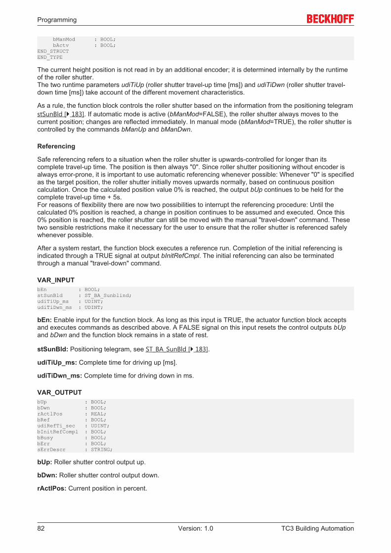
Programming
TC3 Building Automation82 Version: 1.0
bManMod : BOOL; bActv : BOOL;END_STRUCTEND_TYPE
The current height position is not read in by an additional encoder; it is determined internally by the runtimeof the roller shutter.The two runtime parameters udiTiUp (roller shutter travel-up time [ms]) and udiTiDwn (roller shutter travel-down time [ms]) take account of the different movement characteristics.
As a rule, the function block controls the roller shutter based on the information from the positioning telegramstSunBld [} 183]. If automatic mode is active (bManMod=FALSE), the roller shutter always moves to thecurrent position; changes are reflected immediately. In manual mode (bManMod=TRUE), the roller shutter iscontrolled by the commands bManUp and bManDwn.
Referencing
Safe referencing refers to a situation when the roller shutter is upwards-controlled for longer than itscomplete travel-up time. The position is then always "0". Since roller shutter positioning without encoder isalways error-prone, it is important to use automatic referencing whenever possible: Whenever "0" is specifiedas the target position, the roller shutter initially moves upwards normally, based on continuous positioncalculation. Once the calculated position value 0% is reached, the output bUp continues to be held for thecomplete travel-up time + 5s.For reasons of flexibility there are now two possibilities to interrupt the referencing procedure: Until thecalculated 0% position is reached, a change in position continues to be assumed and executed. Once this0% position is reached, the roller shutter can still be moved with the manual "travel-down" command. Thesetwo sensible restrictions make it necessary for the user to ensure that the roller shutter is referenced safelywhenever possible.
After a system restart, the function block executes a reference run. Completion of the initial referencing isindicated through a TRUE signal at output bInitRefCmpl. The initial referencing can also be terminatedthrough a manual "travel-down" command.
VAR_INPUTbEn : BOOL;stSunBld : ST_BA_Sunblind;udiTiUp_ms : UDINT;udiTiDwn_ms : UDINT;
bEn: Enable input for the function block. As long as this input is TRUE, the actuator function block acceptsand executes commands as described above. A FALSE signal on this input resets the control outputs bUpand bDwn and the function block remains in a state of rest.
stSunBld: Positioning telegram, see ST_BA_SunBld [} 183].
udiTiUp_ms: Complete time for driving up [ms].
udiTiDwn_ms: Complete time for driving down in ms.
VAR_OUTPUTbUp : BOOL;bDwn : BOOL;rActlPos : REAL;bRef : BOOL;udiRefTi_sec : UDINT;bInitRefCompl : BOOL;bBusy : BOOL;bErr : BOOL;sErrDescr : STRING;
bUp: Roller shutter control output up.
bDwn: Roller shutter control output down.
rActlPos: Current position in percent.
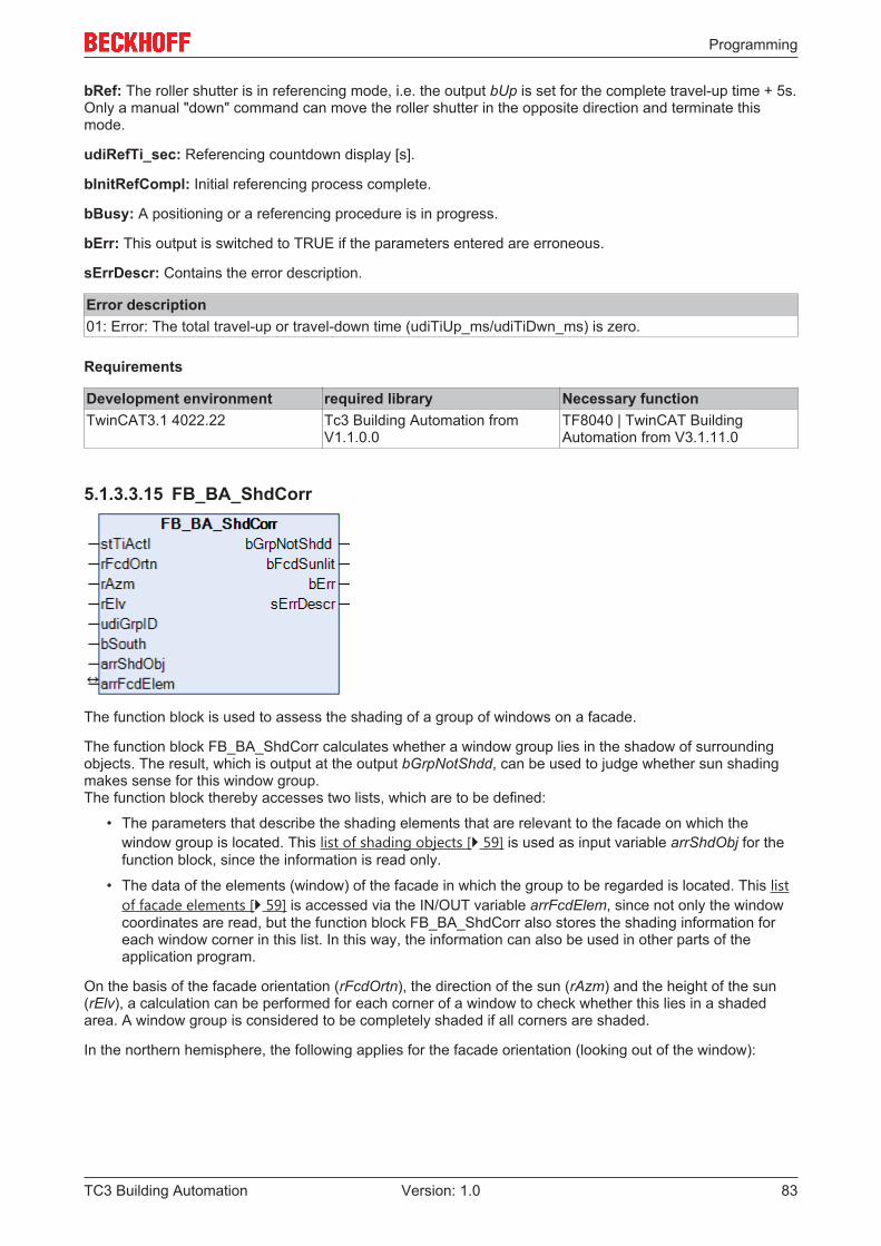
Programming
TC3 Building Automation 83Version: 1.0
bRef: The roller shutter is in referencing mode, i.e. the output bUp is set for the complete travel-up time + 5s.Only a manual "down" command can move the roller shutter in the opposite direction and terminate thismode.
udiRefTi_sec: Referencing countdown display [s].
bInitRefCompl: Initial referencing process complete.
bBusy: A positioning or a referencing procedure is in progress.
bErr: This output is switched to TRUE if the parameters entered are erroneous.
sErrDescr: Contains the error description.
Error description01: Error: The total travel-up or travel-down time (udiTiUp_ms/udiTiDwn_ms) is zero.
Requirements
Development environment required library Necessary functionTwinCAT3.1 4022.22 Tc3 Building Automation from
V1.1.0.0TF8040 | TwinCAT BuildingAutomation from V3.1.11.0
5.1.3.3.15 FB_BA_ShdCorr
The function block is used to assess the shading of a group of windows on a facade.
The function block FB_BA_ShdCorr calculates whether a window group lies in the shadow of surroundingobjects. The result, which is output at the output bGrpNotShdd, can be used to judge whether sun shadingmakes sense for this window group.The function block thereby accesses two lists, which are to be defined:
• The parameters that describe the shading elements that are relevant to the facade on which thewindow group is located. This list of shading objects [} 59] is used as input variable arrShdObj for thefunction block, since the information is read only.
• The data of the elements (window) of the facade in which the group to be regarded is located. This listof facade elements [} 59] is accessed via the IN/OUT variable arrFcdElem, since not only the windowcoordinates are read, but the function block FB_BA_ShdCorr also stores the shading information foreach window corner in this list. In this way, the information can also be used in other parts of theapplication program.
On the basis of the facade orientation (rFcdOrtn), the direction of the sun (rAzm) and the height of the sun(rElv), a calculation can be performed for each corner of a window to check whether this lies in a shadedarea. A window group is considered to be completely shaded if all corners are shaded.
In the northern hemisphere, the following applies for the facade orientation (looking out of the window):
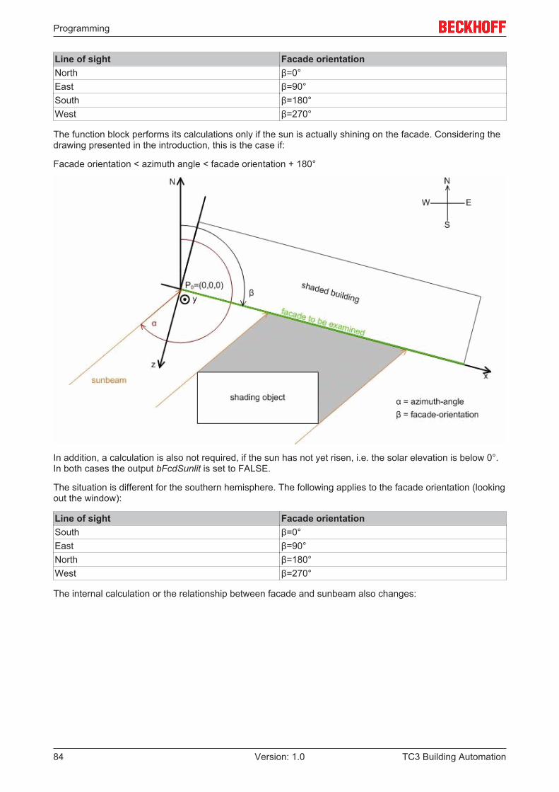
Programming
TC3 Building Automation84 Version: 1.0
Line of sight Facade orientationNorth β=0°East β=90°South β=180°West β=270°
The function block performs its calculations only if the sun is actually shining on the facade. Considering thedrawing presented in the introduction, this is the case if:
Facade orientation < azimuth angle < facade orientation + 180°
In addition, a calculation is also not required, if the sun has not yet risen, i.e. the solar elevation is below 0°.In both cases the output bFcdSunlit is set to FALSE.
The situation is different for the southern hemisphere. The following applies to the facade orientation (lookingout the window):
Line of sight Facade orientationSouth β=0°East β=90°North β=180°West β=270°
The internal calculation or the relationship between facade and sunbeam also changes:
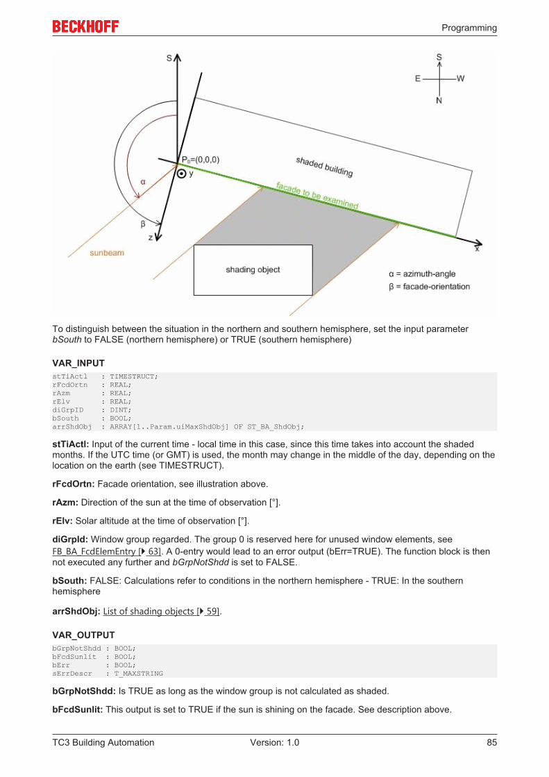
Programming
TC3 Building Automation 85Version: 1.0
To distinguish between the situation in the northern and southern hemisphere, set the input parameterbSouth to FALSE (northern hemisphere) or TRUE (southern hemisphere)
VAR_INPUTstTiActl : TIMESTRUCT;rFcdOrtn : REAL;rAzm : REAL;rElv : REAL;diGrpID : DINT;bSouth : BOOL;arrShdObj : ARRAY[1..Param.uiMaxShdObj] OF ST_BA_ShdObj;
stTiActl: Input of the current time - local time in this case, since this time takes into account the shadedmonths. If the UTC time (or GMT) is used, the month may change in the middle of the day, depending on thelocation on the earth (see TIMESTRUCT).
rFcdOrtn: Facade orientation, see illustration above.
rAzm: Direction of the sun at the time of observation [°].
rElv: Solar altitude at the time of observation [°].
diGrpId: Window group regarded. The group 0 is reserved here for unused window elements, seeFB_BA_FcdElemEntry [} 63]. A 0-entry would lead to an error output (bErr=TRUE). The function block is thennot executed any further and bGrpNotShdd is set to FALSE.
bSouth: FALSE: Calculations refer to conditions in the northern hemisphere - TRUE: In the southernhemisphere
arrShdObj: List of shading objects [} 59].
VAR_OUTPUTbGrpNotShdd : BOOL;bFcdSunlit : BOOL;bErr : BOOL;sErrDescr : T_MAXSTRING
bGrpNotShdd: Is TRUE as long as the window group is not calculated as shaded.
bFcdSunlit: This output is set to TRUE if the sun is shining on the facade. See description above.
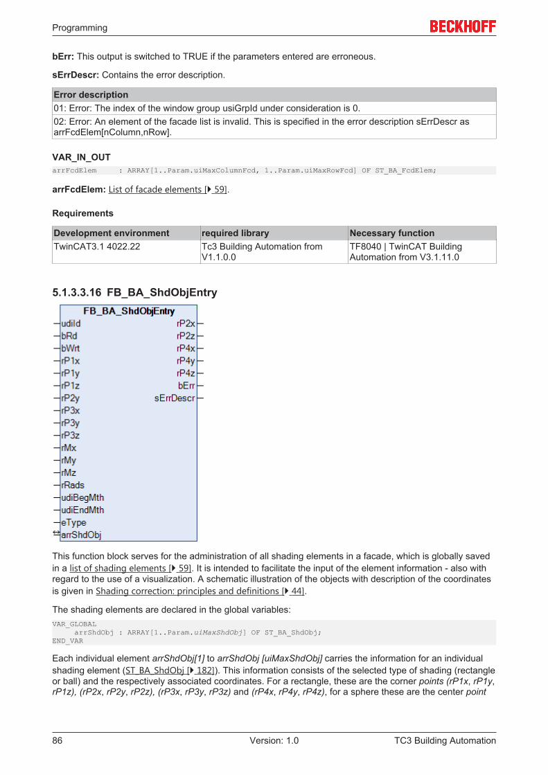
Programming
TC3 Building Automation86 Version: 1.0
bErr: This output is switched to TRUE if the parameters entered are erroneous.
sErrDescr: Contains the error description.
Error description01: Error: The index of the window group usiGrpId under consideration is 0.02: Error: An element of the facade list is invalid. This is specified in the error description sErrDescr asarrFcdElem[nColumn,nRow].
VAR_IN_OUTarrFcdElem : ARRAY[1..Param.uiMaxColumnFcd, 1..Param.uiMaxRowFcd] OF ST_BA_FcdElem;
arrFcdElem: List of facade elements [} 59].
Requirements
Development environment required library Necessary functionTwinCAT3.1 4022.22 Tc3 Building Automation from
V1.1.0.0TF8040 | TwinCAT BuildingAutomation from V3.1.11.0
5.1.3.3.16 FB_BA_ShdObjEntry
This function block serves for the administration of all shading elements in a facade, which is globally savedin a list of shading elements [} 59]. It is intended to facilitate the input of the element information - also withregard to the use of a visualization. A schematic illustration of the objects with description of the coordinatesis given in Shading correction: principles and definitions [} 44].
The shading elements are declared in the global variables:VAR_GLOBAL arrShdObj : ARRAY[1..Param.uiMaxShdObj] OF ST_BA_ShdObj;END_VAR
Each individual element arrShdObj[1] to arrShdObj [uiMaxShdObj] carries the information for an individualshading element (ST_BA_ShdObj [} 182]). This information consists of the selected type of shading (rectangleor ball) and the respectively associated coordinates. For a rectangle, these are the corner points (rP1x, rP1y,rP1z), (rP2x, rP2y, rP2z), (rP3x, rP3y, rP3z) and (rP4x, rP4y, rP4z), for a sphere these are the center point
Programming
TC3 Building Automation 87Version: 1.0
(rMx, rMy, rMz) and the radius rRads. In addition, the phase of the shading can be defined via the inputsudiBegMth and udiEndMth, which is important in the case of objects such as trees that bear no foliage inwinter.
The function block directly accesses the array of this information via the IN-OUT variable arrShdObj.
Note: The fact that the rectangle coordinates rP2x, rP2z, rP4x, rP4y and rP4z are output values results fromthe fact that they are formed from the input parameters:
rP2x = rP1x; rP2z = rP1z; rP4x = rP3x; rP4y = rP1y; rP4z = rP3z;
That limits the input of a square to the extent that the lateral edges stand vertically on the floor (rP2x = rP1xand rP4x = rP3x), that the square has no inclination (rP2z = rP1z and rP4z = rP3z) and can only have adifferent height "upwards", i.e. in the positive y-direction (rP4y = rP1y).
The function block is used in three steps:
• Read• Change• Write
Read
Selection of the element from the list arrShdObj[iId] is based on the entry at udiId. A rising edge on bRdreads the data. These values are assigned to the input and output variables of the function block. These arethe input values rP1x, rP1y, rP1z, rP2y, rP3x, rP3y, rP3z, rMx, rMy, rMz, rRads and the object enumeratoreType and the output values rP2x, rP2z, rP4x, rP4y and rP4z. It is important here that the input values arenot overwritten in the reading step. Hence, all values can initially be displayed in a visualization.
Change
In a next program step the listed input values can then be changed. If a rectangle is preselected at inputeType [} 179] via the value "eObjectTypeTetragon", the output values rP2x, rP2z, rP4x, rP4y and rP4z resultfrom the rectangle coordinates that were entered (see above).
The values entered are constantly checked for plausibility. The output bErr indicates whether the values arevalid (bErr=FALSE). If the value is invalid, a corresponding error message is issued at output sErrDescr.If a rectangle is defined, only the inputs rP1x, rP1y, rP1z, rP2y, rP3x, rP3y and rP3z have to be described;the inputs rMx, rMy, rMz and rRads do not have to be linked. For a sphere definition, only rMx, rMy, rMz andrRads have to be described; the rectangle coordinates can remain unlinked
Write
The parameterized data are written to the list element with the index udiId upon a rising edge on bWrt,regardless of whether they represent valid values or not. The element structure ST_BA_ShdObj [} 182]therefore contains a plausibility bit bVld, which forwards precisely this information to the function blockFB_BA_ShdCorr [} 83] to prevent miscalculations.
This approach is to be regarded only as a proposal. It is naturally also possible to parameterize the functionblock quite normally in one step and to write the values entered to the corresponding list element with arising edge on bWrt.
VAR_INPUTudiId : UDINT;bRd : BOOL;bWrt : BOOL;rP1x : REAL;rP1y : REAL;rP1z : REAL;rP2y : REAL;rP3x : REAL;rP3y : REAL;rP3z : REAL;rMx : REAL;rMy : REAL;rMz : REAL;
Programming
TC3 Building Automation88 Version: 1.0
rRads : REAL;udiBegMth : UDINT;udiEndMth : UDINT;eType : E_BA_ShdObjType;
udiId: Index of the selected element. This refers to the selection of a field element of the array saved in theIN-OUT variable arrShdObj. The variable udiId must not be zero! This is due to the field definition, whichstarts with 1. However, an incorrect input is recognized and displayed as such at bErr/sErrDescr.
bRd: The information of the selected element, arrShdObj[udiId], is read into the function block with a positiveedge at this input and assigned to the input variables rP1x to eType and the output variables rP2x to rP4z. Ifdata are already present on the inputs rP1x to eType at this time, then the data previously read areimmediately overwritten with these data.
bWrt: A positive edge writes the values applied to the inputs rP1x to eType and the values determined andassigned to the outputs rP2x to rP4z to the selected field element arrShdObj[udiId].
rP1x: X-coordinate of point 1 of the shading element (rectangle) [m].
rP1y: Y-coordinate of point 1 of the shading element (rectangle) [m].
rP1z: Z-coordinate of point 1 of the shading element (rectangle) [m].
rP2y: Y-coordinate of point 2 of the shading element (rectangle) [m].
rP3x: X-coordinate of point 3 of the shading element (rectangle) [m].
rP3y: Y-coordinate of point 3 of the shading element (rectangle) [m].
rP3z: Z-coordinate of point 3 of the shading element (rectangle) [m].
rMx: X-coordinate of the center of the shading element (ball) [m].
rMy: Y-coordinate of the center of the shading element (ball) [m].
rMz: Z-coordinate of the center of the shading element (ball) [m].
rRads: Radius of the shading element (ball) [m].
udiBegMth: Beginning of the shading period (month).
udiEndMth: End of the shading period (month).
eType: Selected type of element: Rectangle or sphere (see E_BA_ShdObjType [} 179]).
Remark about the shading period:
The entries for the months may not be 0 or greater than 12, otherwise all combinations are possible.Examples:Start=1, End=1: shading in January.Start=1, End=5: shading from the beginning of January to the end of May.Start=11, End=5: shading from the beginning of November to the end of May (the following year).
VAR_OUTPUTrP2x : REAL;rP2z : REAL;rP4x : REAL;rP4y : REAL;rP4z : REAL;bErr : BOOL;sErrDescr : T_MAXSTRING;
rP2x: Calculated X-coordinate of point 2 of the shading element (rectangle) [m]. See "Note [} 86]" above.
rP2z: Calculated Z-coordinate of point 2 of the shading element (rectangle) [m]. See "Note [} 86]" above.
rP4x: Calculated X-coordinate of point 4 of the shading element (rectangle) [m]. See "Note [} 86]" above.
rP4y: Calculated Y-coordinate of point 4 of the shading element (rectangle) [m]. See "Note [} 86]" above.
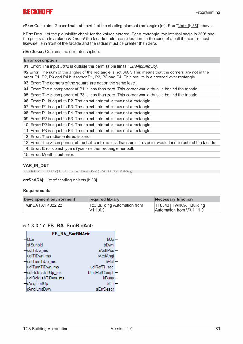
Programming
TC3 Building Automation 89Version: 1.0
rP4z: Calculated Z-coordinate of point 4 of the shading element (rectangle) [m]. See "Note [} 86]" above.
bErr: Result of the plausibility check for the values entered. For a rectangle, the internal angle is 360° andthe points are in a plane in front of the facade under consideration. In the case of a ball the center mustlikewise lie in front of the facade and the radius must be greater than zero.
sErrDescr: Contains the error description.
Error description01: Error: The input udiId is outside the permissible limits 1..uiMaxShdObj.02 Error: The sum of the angles of the rectangle is not 360°. This means that the corners are not in theorder P1, P2, P3 and P4 but rather P1, P3, P2 and P4. This results in a crossed-over rectangle.03: Error: The corners of the square are not on the same level.04: Error: The z-component of P1 is less than zero. This corner would thus lie behind the facade.05: Error: The z-component of P3 is less than zero. This corner would thus lie behind the facade.06: Error: P1 is equal to P2. The object entered is thus not a rectangle.07: Error: P1 is equal to P3. The object entered is thus not a rectangle.08: Error: P1 is equal to P4. The object entered is thus not a rectangle.09: Error: P2 is equal to P3. The object entered is thus not a rectangle.10: Error: P2 is equal to P4. The object entered is thus not a rectangle.11: Error: P3 is equal to P4. The object entered is thus not a rectangle.12: Error: The radius entered is zero.13: Error: The z-component of the ball center is less than zero. This point would thus lie behind the facade.14: Error: Error object type eType - neither rectangle nor ball.15: Error: Month input error.
VAR_IN_OUTarrShdObj : ARRAY[1..Param.uiMaxShdObj] OF ST_BA_ShdObj;
arrShdObj: List of shading objects [} 59].
Requirements
Development environment required library Necessary functionTwinCAT3.1 4022.22 Tc3 Building Automation from
V1.1.0.0TF8040 | TwinCAT BuildingAutomation from V3.1.11.0
5.1.3.3.17 FB_BA_SunBldActr
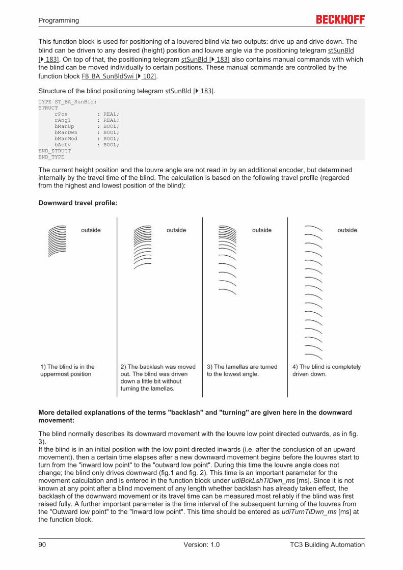
Programming
TC3 Building Automation90 Version: 1.0
This function block is used for positioning of a louvered blind via two outputs: drive up and drive down. Theblind can be driven to any desired (height) position and louvre angle via the positioning telegram stSunBld[} 183]. On top of that, the positioning telegram stSunBld [} 183] also contains manual commands with whichthe blind can be moved individually to certain positions. These manual commands are controlled by thefunction block FB_BA_SunBldSwi [} 102].
Structure of the blind positioning telegram stSunBld [} 183].TYPE ST_BA_SunBld:STRUCT rPos : REAL; rAngl : REAL; bManUp : BOOL; bManDwn : BOOL; bManMod : BOOL; bActv : BOOL;END_STRUCTEND_TYPE
The current height position and the louvre angle are not read in by an additional encoder, but determinedinternally by the travel time of the blind. The calculation is based on the following travel profile (regardedfrom the highest and lowest position of the blind):
Downward travel profile:
More detailed explanations of the terms "backlash" and "turning" are given here in the downwardmovement:
The blind normally describes its downward movement with the louvre low point directed outwards, as in fig.3).If the blind is in an initial position with the low point directed inwards (i.e. after the conclusion of an upwardmovement), then a certain time elapses after a new downward movement begins before the louvres start toturn from the "inward low point" to the "outward low point". During this time the louvre angle does notchange; the blind only drives downward (fig.1 and fig. 2). This time is an important parameter for themovement calculation and is entered in the function block under udiBckLshTiDwn_ms [ms]. Since it is notknown at any point after a blind movement of any length whether backlash has already taken effect, thebacklash of the downward movement or its travel time can be measured most reliably if the blind was firstraised fully. A further important parameter is the time interval of the subsequent turning of the louvres fromthe "Outward low point" to the "Inward low point". This time should be entered as udiTurnTiDwn_ms [ms] atthe function block.
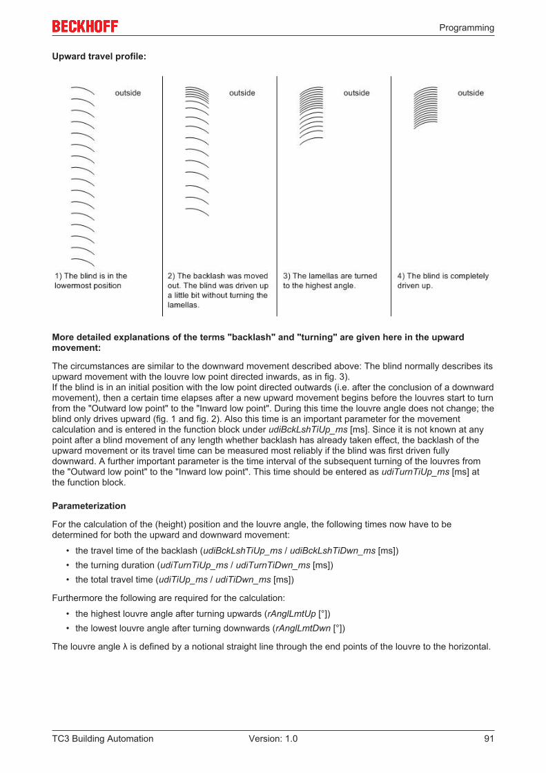
Programming
TC3 Building Automation 91Version: 1.0
Upward travel profile:
More detailed explanations of the terms "backlash" and "turning" are given here in the upwardmovement:
The circumstances are similar to the downward movement described above: The blind normally describes itsupward movement with the louvre low point directed inwards, as in fig. 3).If the blind is in an initial position with the low point directed outwards (i.e. after the conclusion of a downwardmovement), then a certain time elapses after a new upward movement begins before the louvres start to turnfrom the "Outward low point" to the "Inward low point". During this time the louvre angle does not change; theblind only drives upward (fig. 1 and fig. 2). Also this time is an important parameter for the movementcalculation and is entered in the function block under udiBckLshTiUp_ms [ms]. Since it is not known at anypoint after a blind movement of any length whether backlash has already taken effect, the backlash of theupward movement or its travel time can be measured most reliably if the blind was first driven fullydownward. A further important parameter is the time interval of the subsequent turning of the louvres fromthe "Outward low point" to the "Inward low point". This time should be entered as udiTurnTiUp_ms [ms] atthe function block.
Parameterization
For the calculation of the (height) position and the louvre angle, the following times now have to bedetermined for both the upward and downward movement:
• the travel time of the backlash (udiBckLshTiUp_ms / udiBckLshTiDwn_ms [ms])• the turning duration (udiTurnTiUp_ms / udiTurnTiDwn_ms [ms])• the total travel time (udiTiUp_ms / udiTiDwn_ms [ms])
Furthermore the following are required for the calculation:
• the highest louvre angle after turning upwards (rAnglLmtUp [°])• the lowest louvre angle after turning downwards (rAnglLmtDwn [°])
The louvre angle λ is defined by a notional straight line through the end points of the louvre to the horizontal.
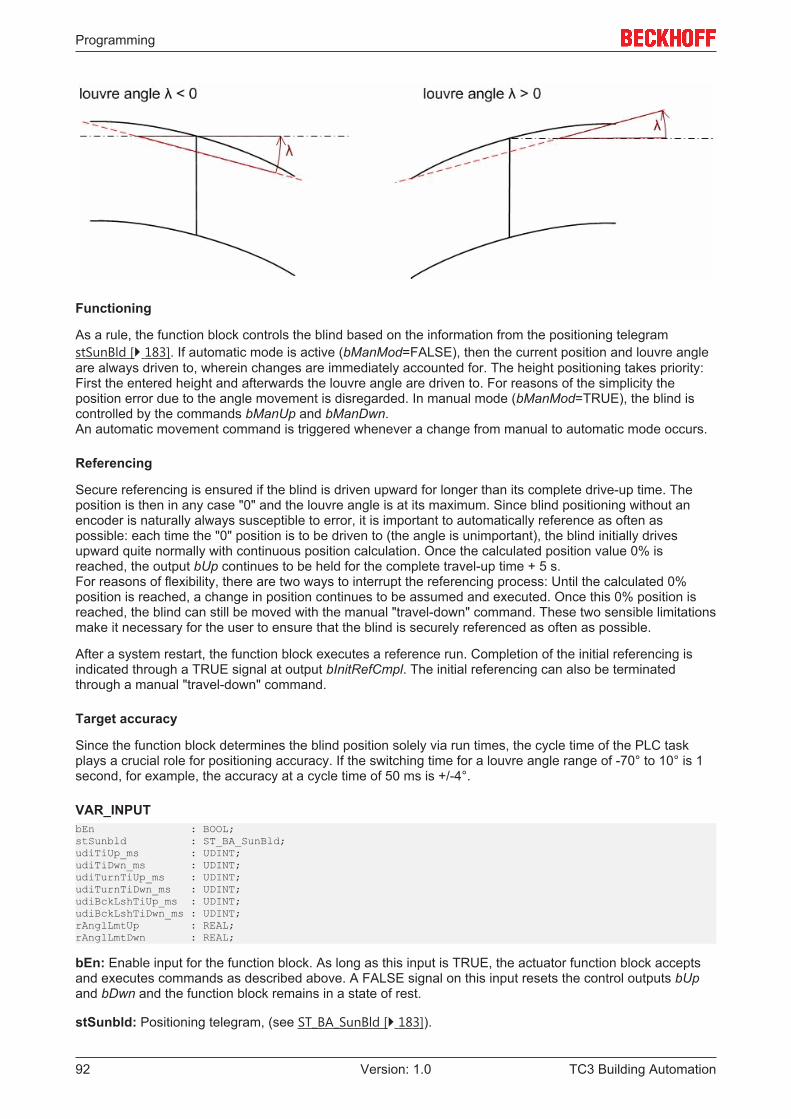
Programming
TC3 Building Automation92 Version: 1.0
Functioning
As a rule, the function block controls the blind based on the information from the positioning telegramstSunBld [} 183]. If automatic mode is active (bManMod=FALSE), then the current position and louvre angleare always driven to, wherein changes are immediately accounted for. The height positioning takes priority:First the entered height and afterwards the louvre angle are driven to. For reasons of the simplicity theposition error due to the angle movement is disregarded. In manual mode (bManMod=TRUE), the blind iscontrolled by the commands bManUp and bManDwn.An automatic movement command is triggered whenever a change from manual to automatic mode occurs.
Referencing
Secure referencing is ensured if the blind is driven upward for longer than its complete drive-up time. Theposition is then in any case "0" and the louvre angle is at its maximum. Since blind positioning without anencoder is naturally always susceptible to error, it is important to automatically reference as often aspossible: each time the "0" position is to be driven to (the angle is unimportant), the blind initially drivesupward quite normally with continuous position calculation. Once the calculated position value 0% isreached, the output bUp continues to be held for the complete travel-up time + 5 s.For reasons of flexibility, there are two ways to interrupt the referencing process: Until the calculated 0%position is reached, a change in position continues to be assumed and executed. Once this 0% position isreached, the blind can still be moved with the manual "travel-down" command. These two sensible limitationsmake it necessary for the user to ensure that the blind is securely referenced as often as possible.
After a system restart, the function block executes a reference run. Completion of the initial referencing isindicated through a TRUE signal at output bInitRefCmpl. The initial referencing can also be terminatedthrough a manual "travel-down" command.
Target accuracy
Since the function block determines the blind position solely via run times, the cycle time of the PLC taskplays a crucial role for positioning accuracy. If the switching time for a louvre angle range of -70° to 10° is 1second, for example, the accuracy at a cycle time of 50 ms is +/-4°.
VAR_INPUTbEn : BOOL;stSunbld : ST_BA_SunBld;udiTiUp_ms : UDINT;udiTiDwn_ms : UDINT;udiTurnTiUp_ms : UDINT;udiTurnTiDwn_ms : UDINT;udiBckLshTiUp_ms : UDINT;udiBckLshTiDwn_ms : UDINT;rAnglLmtUp : REAL;rAnglLmtDwn : REAL;
bEn: Enable input for the function block. As long as this input is TRUE, the actuator function block acceptsand executes commands as described above. A FALSE signal on this input resets the control outputs bUpand bDwn and the function block remains in a state of rest.
stSunbld: Positioning telegram, (see ST_BA_SunBld [} 183]).
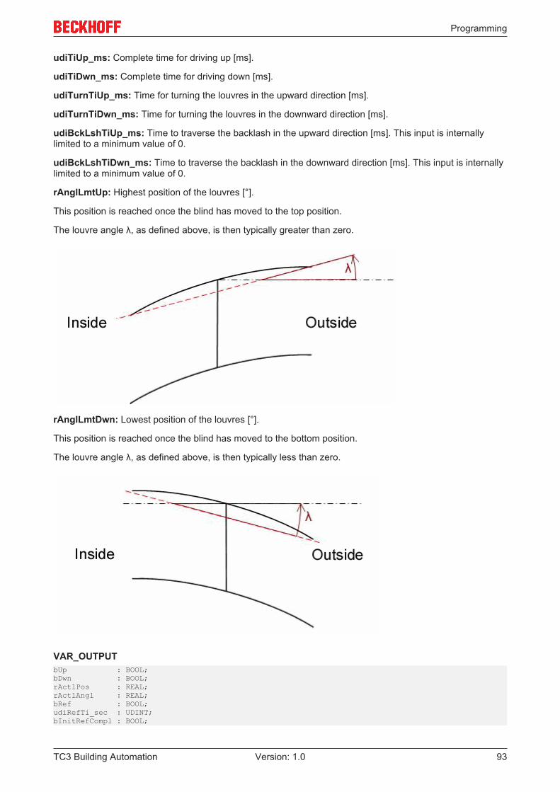
Programming
TC3 Building Automation 93Version: 1.0
udiTiUp_ms: Complete time for driving up [ms].
udiTiDwn_ms: Complete time for driving down [ms].
udiTurnTiUp_ms: Time for turning the louvres in the upward direction [ms].
udiTurnTiDwn_ms: Time for turning the louvres in the downward direction [ms].
udiBckLshTiUp_ms: Time to traverse the backlash in the upward direction [ms]. This input is internallylimited to a minimum value of 0.
udiBckLshTiDwn_ms: Time to traverse the backlash in the downward direction [ms]. This input is internallylimited to a minimum value of 0.
rAnglLmtUp: Highest position of the louvres [°].
This position is reached once the blind has moved to the top position.
The louvre angle λ, as defined above, is then typically greater than zero.
rAnglLmtDwn: Lowest position of the louvres [°].
This position is reached once the blind has moved to the bottom position.
The louvre angle λ, as defined above, is then typically less than zero.
VAR_OUTPUTbUp : BOOL;bDwn : BOOL;rActlPos : REAL;rActlAngl : REAL;bRef : BOOL;udiRefTi_sec : UDINT;bInitRefCompl : BOOL;
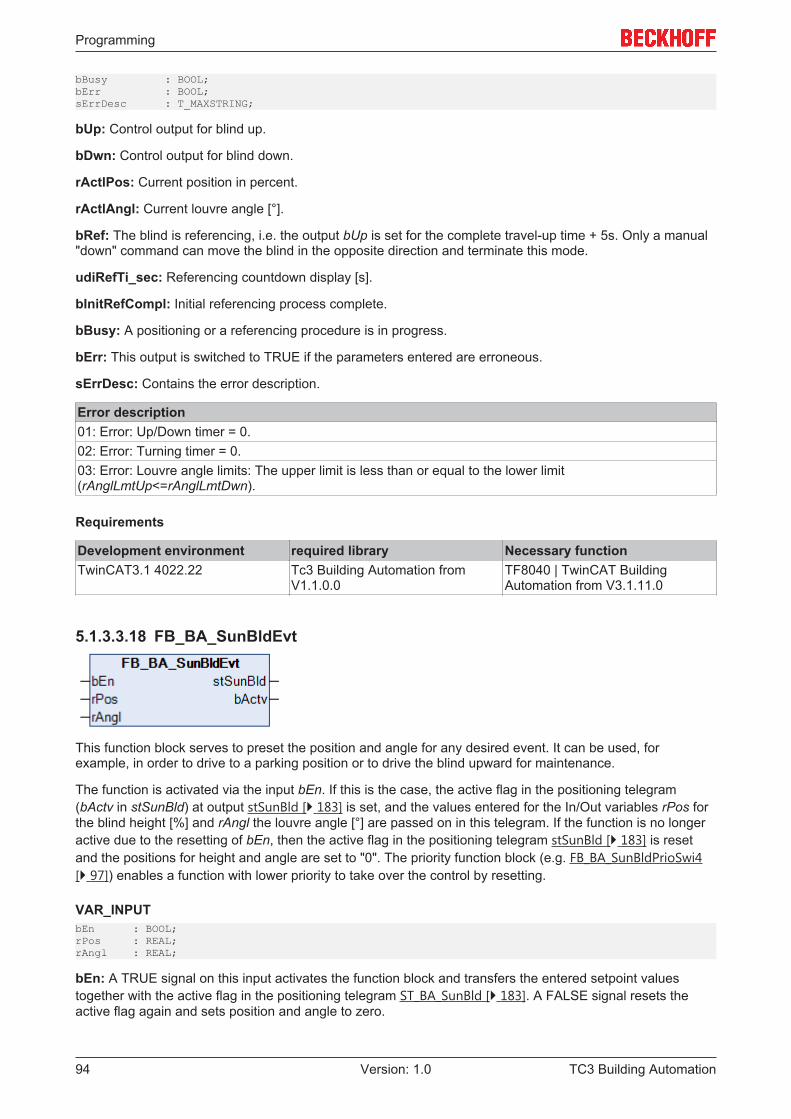
Programming
TC3 Building Automation94 Version: 1.0
bBusy : BOOL;bErr : BOOL;sErrDesc : T_MAXSTRING;
bUp: Control output for blind up.
bDwn: Control output for blind down.
rActlPos: Current position in percent.
rActlAngl: Current louvre angle [°].
bRef: The blind is referencing, i.e. the output bUp is set for the complete travel-up time + 5s. Only a manual"down" command can move the blind in the opposite direction and terminate this mode.
udiRefTi_sec: Referencing countdown display [s].
bInitRefCompl: Initial referencing process complete.
bBusy: A positioning or a referencing procedure is in progress.
bErr: This output is switched to TRUE if the parameters entered are erroneous.
sErrDesc: Contains the error description.
Error description01: Error: Up/Down timer = 0.02: Error: Turning timer = 0.03: Error: Louvre angle limits: The upper limit is less than or equal to the lower limit(rAnglLmtUp<=rAnglLmtDwn).
Requirements
Development environment required library Necessary functionTwinCAT3.1 4022.22 Tc3 Building Automation from
V1.1.0.0TF8040 | TwinCAT BuildingAutomation from V3.1.11.0
5.1.3.3.18 FB_BA_SunBldEvt
This function block serves to preset the position and angle for any desired event. It can be used, forexample, in order to drive to a parking position or to drive the blind upward for maintenance.
The function is activated via the input bEn. If this is the case, the active flag in the positioning telegram(bActv in stSunBld) at output stSunBld [} 183] is set, and the values entered for the In/Out variables rPos forthe blind height [%] and rAngl the louvre angle [°] are passed on in this telegram. If the function is no longeractive due to the resetting of bEn, then the active flag in the positioning telegram stSunBld [} 183] is resetand the positions for height and angle are set to "0". The priority function block (e.g. FB_BA_SunBldPrioSwi4[} 97]) enables a function with lower priority to take over the control by resetting.
VAR_INPUTbEn : BOOL;rPos : REAL;rAngl : REAL;
bEn: A TRUE signal on this input activates the function block and transfers the entered setpoint valuestogether with the active flag in the positioning telegram ST_BA_SunBld [} 183]. A FALSE signal resets theactive flag again and sets position and angle to zero.
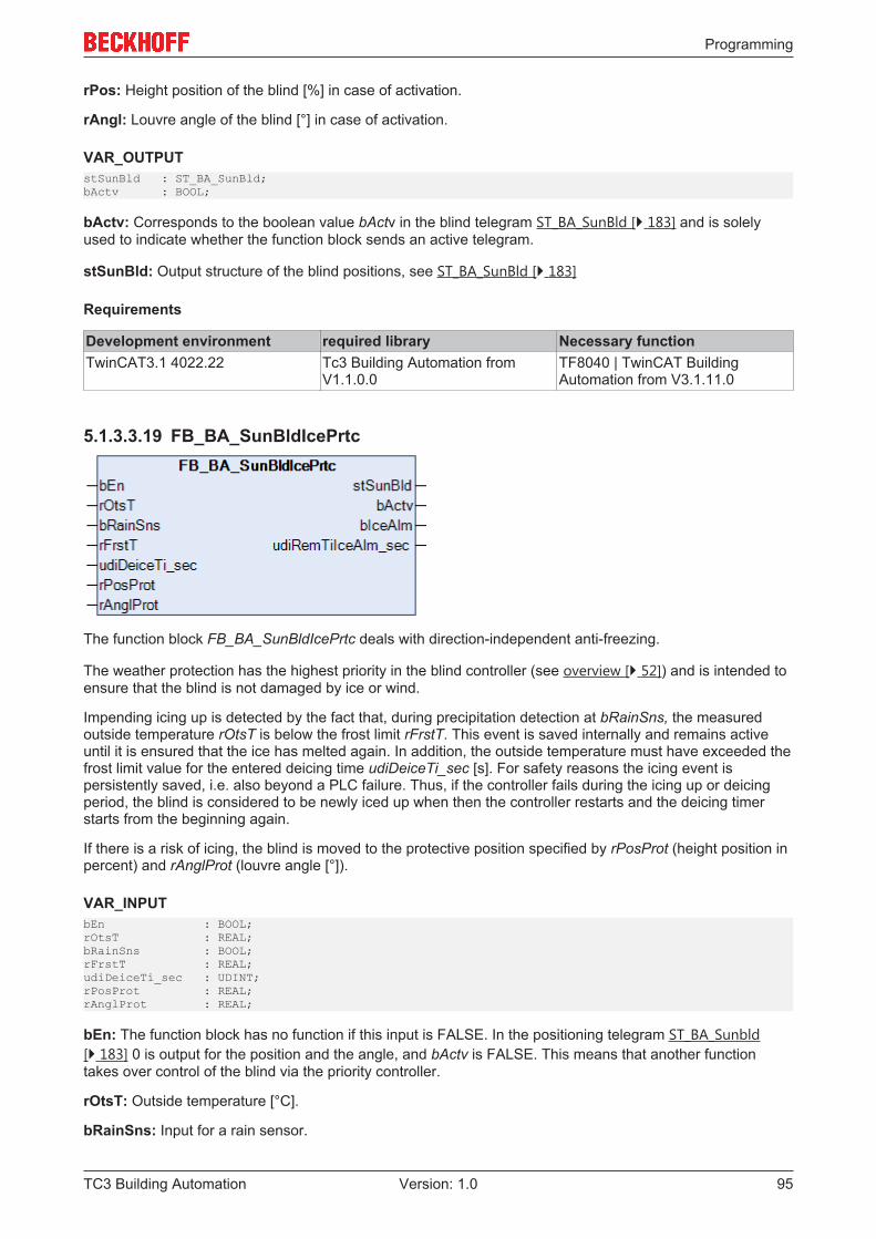
Programming
TC3 Building Automation 95Version: 1.0
rPos: Height position of the blind [%] in case of activation.
rAngl: Louvre angle of the blind [°] in case of activation.
VAR_OUTPUTstSunBld : ST_BA_SunBld;bActv : BOOL;
bActv: Corresponds to the boolean value bActv in the blind telegram ST_BA_SunBld [} 183] and is solelyused to indicate whether the function block sends an active telegram.
stSunBld: Output structure of the blind positions, see ST_BA_SunBld [} 183]
Requirements
Development environment required library Necessary functionTwinCAT3.1 4022.22 Tc3 Building Automation from
V1.1.0.0TF8040 | TwinCAT BuildingAutomation from V3.1.11.0
5.1.3.3.19 FB_BA_SunBldIcePrtc
The function block FB_BA_SunBldIcePrtc deals with direction-independent anti-freezing.
The weather protection has the highest priority in the blind controller (see overview [} 52]) and is intended toensure that the blind is not damaged by ice or wind.
Impending icing up is detected by the fact that, during precipitation detection at bRainSns, the measuredoutside temperature rOtsT is below the frost limit rFrstT. This event is saved internally and remains activeuntil it is ensured that the ice has melted again. In addition, the outside temperature must have exceeded thefrost limit value for the entered deicing time udiDeiceTi_sec [s]. For safety reasons the icing event ispersistently saved, i.e. also beyond a PLC failure. Thus, if the controller fails during the icing up or deicingperiod, the blind is considered to be newly iced up when then the controller restarts and the deicing timerstarts from the beginning again.
If there is a risk of icing, the blind is moved to the protective position specified by rPosProt (height position inpercent) and rAnglProt (louvre angle [°]).
VAR_INPUTbEn : BOOL;rOtsT : REAL;bRainSns : BOOL;rFrstT : REAL;udiDeiceTi_sec : UDINT;rPosProt : REAL;rAnglProt : REAL;
bEn: The function block has no function if this input is FALSE. In the positioning telegram ST_BA_Sunbld[} 183] 0 is output for the position and the angle, and bActv is FALSE. This means that another functiontakes over control of the blind via the priority controller.
rOtsT: Outside temperature [°C].
bRainSns: Input for a rain sensor.
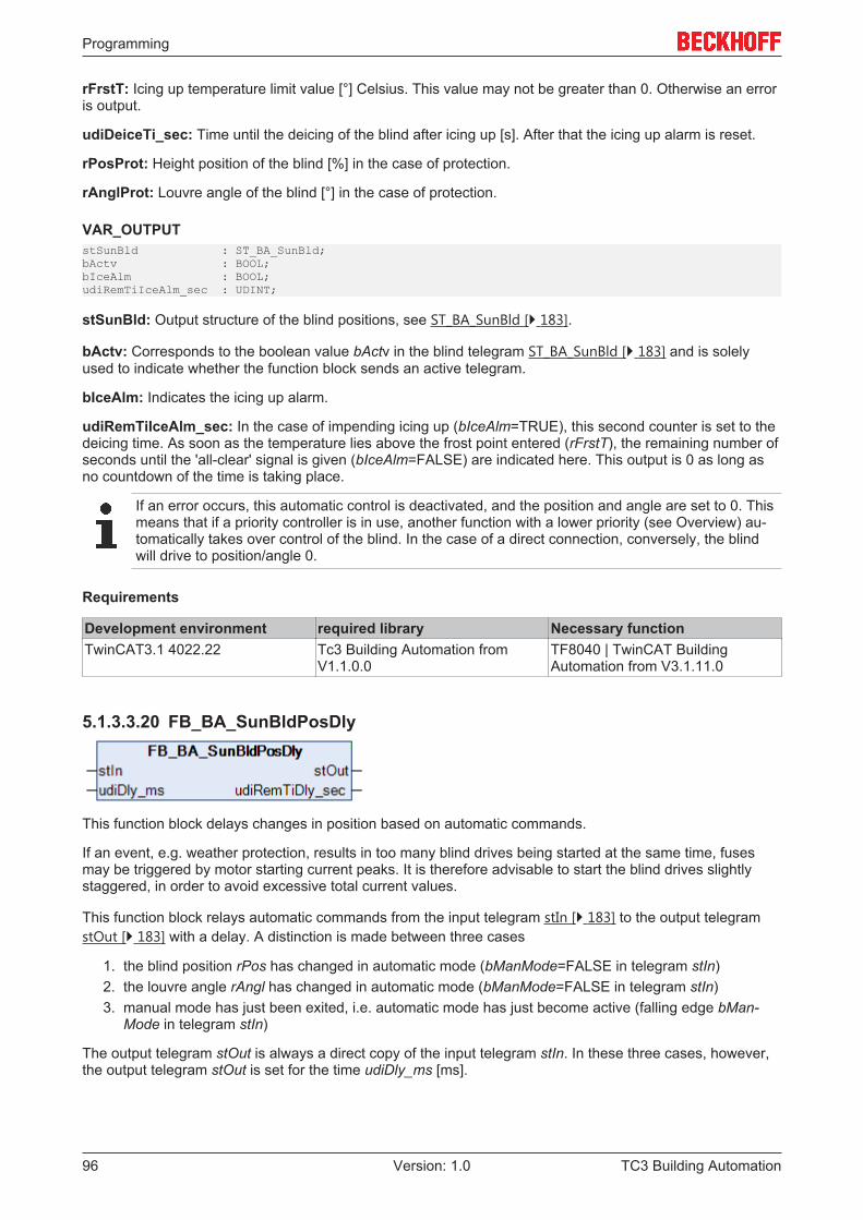
Programming
TC3 Building Automation96 Version: 1.0
rFrstT: Icing up temperature limit value [°] Celsius. This value may not be greater than 0. Otherwise an erroris output.
udiDeiceTi_sec: Time until the deicing of the blind after icing up [s]. After that the icing up alarm is reset.
rPosProt: Height position of the blind [%] in the case of protection.
rAnglProt: Louvre angle of the blind [°] in the case of protection.
VAR_OUTPUTstSunBld : ST_BA_SunBld;bActv : BOOL;bIceAlm : BOOL;udiRemTiIceAlm_sec : UDINT;
stSunBld: Output structure of the blind positions, see ST_BA_SunBld [} 183].
bActv: Corresponds to the boolean value bActv in the blind telegram ST_BA_SunBld [} 183] and is solelyused to indicate whether the function block sends an active telegram.
bIceAlm: Indicates the icing up alarm.
udiRemTiIceAlm_sec: In the case of impending icing up (bIceAlm=TRUE), this second counter is set to thedeicing time. As soon as the temperature lies above the frost point entered (rFrstT), the remaining number ofseconds until the 'all-clear' signal is given (bIceAlm=FALSE) are indicated here. This output is 0 as long asno countdown of the time is taking place.
If an error occurs, this automatic control is deactivated, and the position and angle are set to 0. Thismeans that if a priority controller is in use, another function with a lower priority (see Overview) au-tomatically takes over control of the blind. In the case of a direct connection, conversely, the blindwill drive to position/angle 0.
Requirements
Development environment required library Necessary functionTwinCAT3.1 4022.22 Tc3 Building Automation from
V1.1.0.0TF8040 | TwinCAT BuildingAutomation from V3.1.11.0
5.1.3.3.20 FB_BA_SunBldPosDly
This function block delays changes in position based on automatic commands.
If an event, e.g. weather protection, results in too many blind drives being started at the same time, fusesmay be triggered by motor starting current peaks. It is therefore advisable to start the blind drives slightlystaggered, in order to avoid excessive total current values.
This function block relays automatic commands from the input telegram stIn [} 183] to the output telegramstOut [} 183] with a delay. A distinction is made between three cases
1. the blind position rPos has changed in automatic mode (bManMode=FALSE in telegram stIn)2. the louvre angle rAngl has changed in automatic mode (bManMode=FALSE in telegram stIn)3. manual mode has just been exited, i.e. automatic mode has just become active (falling edge bMan-
Mode in telegram stIn)
The output telegram stOut is always a direct copy of the input telegram stIn. In these three cases, however,the output telegram stOut is set for the time udiDly_ms [ms].
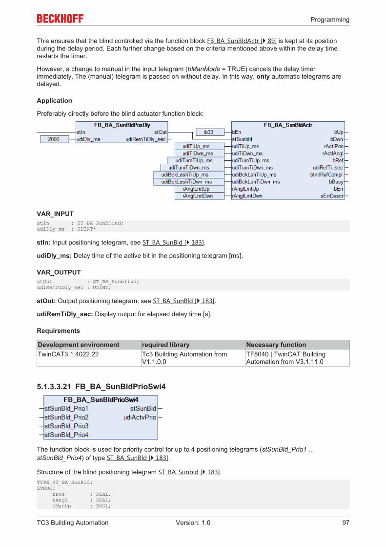
Programming
TC3 Building Automation 97Version: 1.0
This ensures that the blind controlled via the function block FB_BA_SunBldActr [} 89] is kept at its positionduring the delay period. Each further change based on the criteria mentioned above within the delay timerestarts the timer.
However, a change to manual in the input telegram (bManMode = TRUE) cancels the delay timerimmediately. The (manual) telegram is passed on without delay. In this way, only automatic telegrams aredelayed.
Application
Preferably directly before the blind actuator function block:
VAR_INPUTstIn : ST_BA_Sunblind;udiDly_ms : UDINT;
stIn: Input positioning telegram, see ST_BA_SunBld [} 183].
udiDly_ms: Delay time of the active bit in the positioning telegram [ms].
VAR_OUTPUTstOut : ST_BA_Sunblind;udiRemTiDly_sec : UDINT;
stOut: Output positioning telegram, see ST_BA_SunBld [} 183].
udiRemTiDly_sec: Display output for elapsed delay time [s].
Requirements
Development environment required library Necessary functionTwinCAT3.1 4022.22 Tc3 Building Automation from
V1.1.0.0TF8040 | TwinCAT BuildingAutomation from V3.1.11.0
5.1.3.3.21 FB_BA_SunBldPrioSwi4
The function block is used for priority control for up to 4 positioning telegrams (stSunBld_Prio1 ...stSunBld_Prio4) of type ST_BA_SunBld [} 183].
Structure of the blind positioning telegram ST_BA_Sunbld [} 183].TYPE ST_BA_SunBld:STRUCT rPos : REAL; rAngl : REAL; bManUp : BOOL;
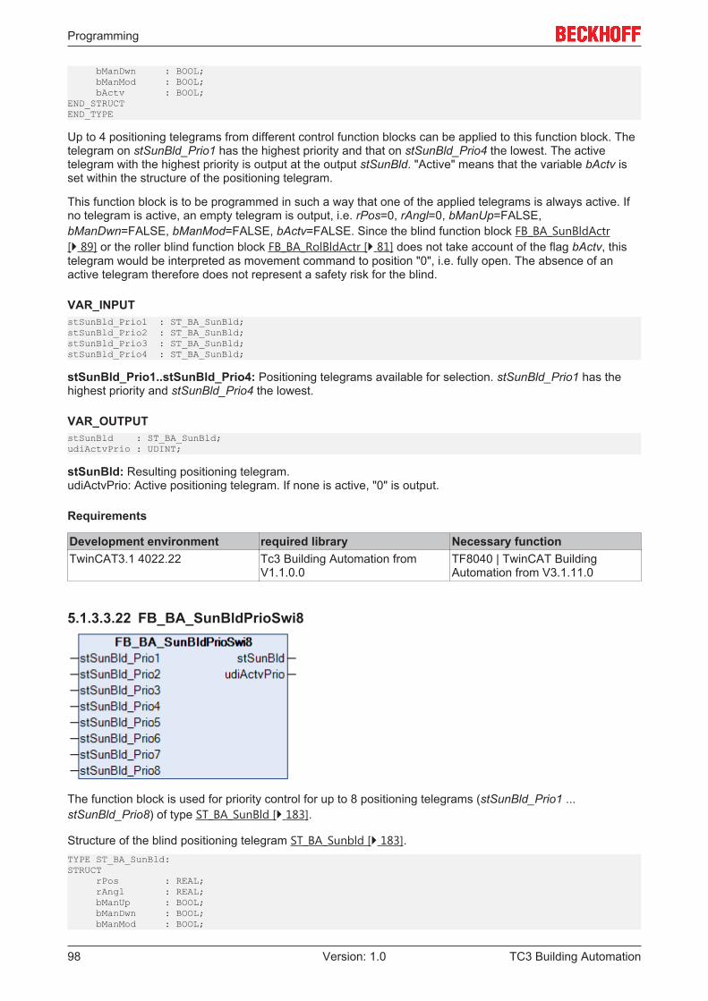
Programming
TC3 Building Automation98 Version: 1.0
bManDwn : BOOL; bManMod : BOOL; bActv : BOOL;END_STRUCTEND_TYPE
Up to 4 positioning telegrams from different control function blocks can be applied to this function block. Thetelegram on stSunBld_Prio1 has the highest priority and that on stSunBld_Prio4 the lowest. The activetelegram with the highest priority is output at the output stSunBld. "Active" means that the variable bActv isset within the structure of the positioning telegram.
This function block is to be programmed in such a way that one of the applied telegrams is always active. Ifno telegram is active, an empty telegram is output, i.e. rPos=0, rAngl=0, bManUp=FALSE,bManDwn=FALSE, bManMod=FALSE, bActv=FALSE. Since the blind function block FB_BA_SunBldActr[} 89] or the roller blind function block FB_BA_RolBldActr [} 81] does not take account of the flag bActv, thistelegram would be interpreted as movement command to position "0", i.e. fully open. The absence of anactive telegram therefore does not represent a safety risk for the blind.
VAR_INPUTstSunBld_Prio1 : ST_BA_SunBld;stSunBld_Prio2 : ST_BA_SunBld;stSunBld_Prio3 : ST_BA_SunBld;stSunBld_Prio4 : ST_BA_SunBld;
stSunBld_Prio1..stSunBld_Prio4: Positioning telegrams available for selection. stSunBld_Prio1 has thehighest priority and stSunBld_Prio4 the lowest.
VAR_OUTPUTstSunBld : ST_BA_SunBld;udiActvPrio : UDINT;
stSunBld: Resulting positioning telegram.udiActvPrio: Active positioning telegram. If none is active, "0" is output.
Requirements
Development environment required library Necessary functionTwinCAT3.1 4022.22 Tc3 Building Automation from
V1.1.0.0TF8040 | TwinCAT BuildingAutomation from V3.1.11.0
5.1.3.3.22 FB_BA_SunBldPrioSwi8
The function block is used for priority control for up to 8 positioning telegrams (stSunBld_Prio1 ...stSunBld_Prio8) of type ST_BA_SunBld [} 183].
Structure of the blind positioning telegram ST_BA_Sunbld [} 183].TYPE ST_BA_SunBld:STRUCT rPos : REAL; rAngl : REAL; bManUp : BOOL; bManDwn : BOOL; bManMod : BOOL;

Programming
TC3 Building Automation 99Version: 1.0
bActv : BOOL;END_STRUCTEND_TYPE
Up to 8 positioning telegrams from different control function blocks can be applied to this function block. Thetelegram on stSunBld_Prio1 has the highest priority and that on stSunBld_Prio8 the lowest. The activetelegram with the highest priority is output at the output stSunBld. "Active" means that the variable bActv isset within the structure of the positioning telegram.
This function block is to be programmed in such a way that one of the applied telegrams is always active. Ifno telegram is active, an empty telegram is output, i.e. rPos=0, rAngl=0, bManUp=FALSE,bManDwn=FALSE, bManMod=FALSE, bActv=FALSE. Since the blind function block FB_BA_SunBldActr[} 89] or the roller blind function block FB_BA_RolBldActr [} 81] does not take account of the flag bActv, thistelegram would be interpreted as movement command to position "0", i.e. fully open. The absence of anactive telegram therefore does not represent a safety risk for the blind.
VAR_INPUTstSunBld_Prio1 : ST_BA_SunBld;stSunBld_Prio2 : ST_BA_SunBld;stSunBld_Prio3 : ST_BA_SunBld;stSunBld_Prio4 : ST_BA_SunBld;stSunBld_Prio5 : ST_BA_SunBld;stSunBld_Prio6 : ST_BA_SunBld;stSunBld_Prio7 : ST_BA_SunBld;stSunBld_Prio8 : ST_BA_SunBld;
stSunBld_Prio1..stSunBld_Prio8: Positioning telegrams available for selection. stSunBld_Prio1 has thehighest priority and stSunBld_Prio8 the lowest.
VAR_OUTPUTstSunBld : ST_BA_SunBld;udiActvPrio : UDINT;
stSunBld: Resulting positioning telegram.udiActvPrio: Active positioning telegram. If none is active, "0" is output.
Requirements
Development environment required library Necessary functionTwinCAT3.1 4022.22 Tc3 Building Automation from
V1.1.0.0TF8040 | TwinCAT BuildingAutomation from V3.1.11.0
5.1.3.3.23 FB_BA_SunBldScn
This function block represents an extension of the manual controller FB_BA_SunBldSwi [} 102] by a scenememory and a call function. The blind control FB_BA_SunBldActr [} 89] or the roller blind controlFB_BA_RolBldActr [} 81] can be active in manual mode and also directly target previously stored positions(scenes). Up to 21 scenes can be saved.
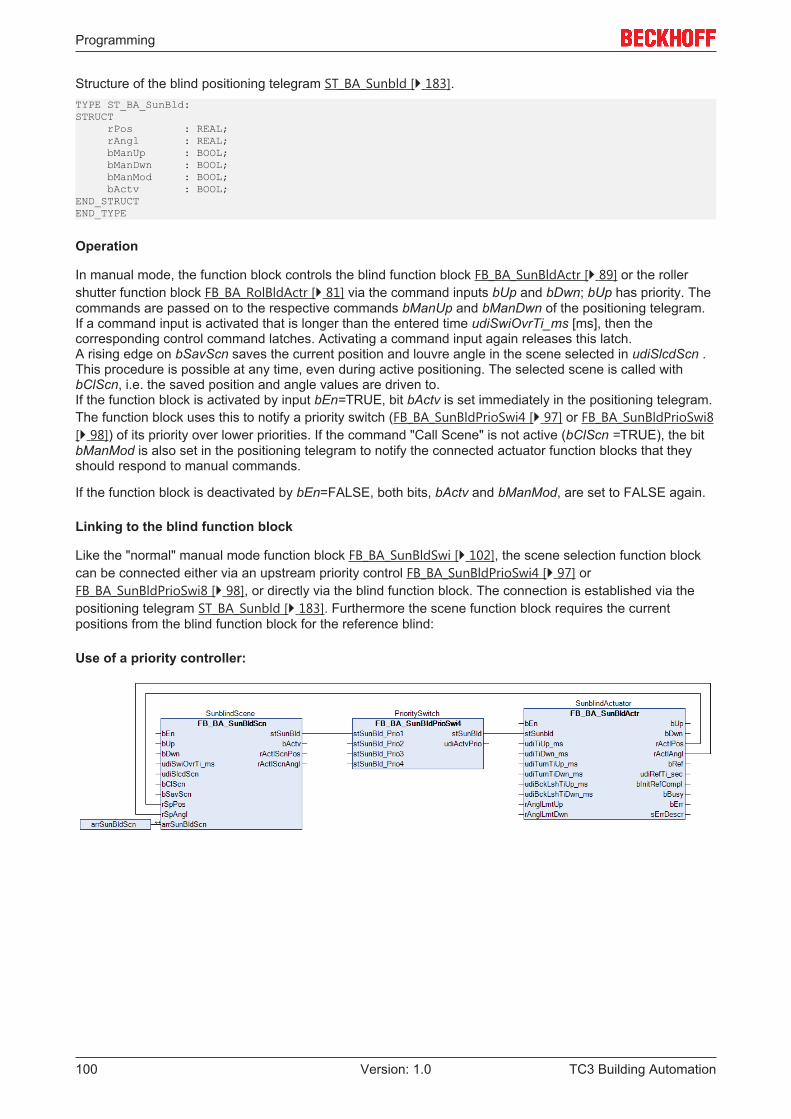
Programming
TC3 Building Automation100 Version: 1.0
Structure of the blind positioning telegram ST_BA_Sunbld [} 183].TYPE ST_BA_SunBld:STRUCT rPos : REAL; rAngl : REAL; bManUp : BOOL; bManDwn : BOOL; bManMod : BOOL; bActv : BOOL;END_STRUCTEND_TYPE
Operation
In manual mode, the function block controls the blind function block FB_BA_SunBldActr [} 89] or the rollershutter function block FB_BA_RolBldActr [} 81] via the command inputs bUp and bDwn; bUp has priority. Thecommands are passed on to the respective commands bManUp and bManDwn of the positioning telegram.If a command input is activated that is longer than the entered time udiSwiOvrTi_ms [ms], then thecorresponding control command latches. Activating a command input again releases this latch.A rising edge on bSavScn saves the current position and louvre angle in the scene selected in udiSlcdScn .This procedure is possible at any time, even during active positioning. The selected scene is called withbClScn, i.e. the saved position and angle values are driven to.If the function block is activated by input bEn=TRUE, bit bActv is set immediately in the positioning telegram.The function block uses this to notify a priority switch (FB_BA_SunBldPrioSwi4 [} 97] or FB_BA_SunBldPrioSwi8[} 98]) of its priority over lower priorities. If the command "Call Scene" is not active (bClScn =TRUE), the bitbManMod is also set in the positioning telegram to notify the connected actuator function blocks that theyshould respond to manual commands.
If the function block is deactivated by bEn=FALSE, both bits, bActv and bManMod, are set to FALSE again.
Linking to the blind function block
Like the "normal" manual mode function block FB_BA_SunBldSwi [} 102], the scene selection function blockcan be connected either via an upstream priority control FB_BA_SunBldPrioSwi4 [} 97] orFB_BA_SunBldPrioSwi8 [} 98], or directly via the blind function block. The connection is established via thepositioning telegram ST_BA_Sunbld [} 183]. Furthermore the scene function block requires the currentpositions from the blind function block for the reference blind:
Use of a priority controller:
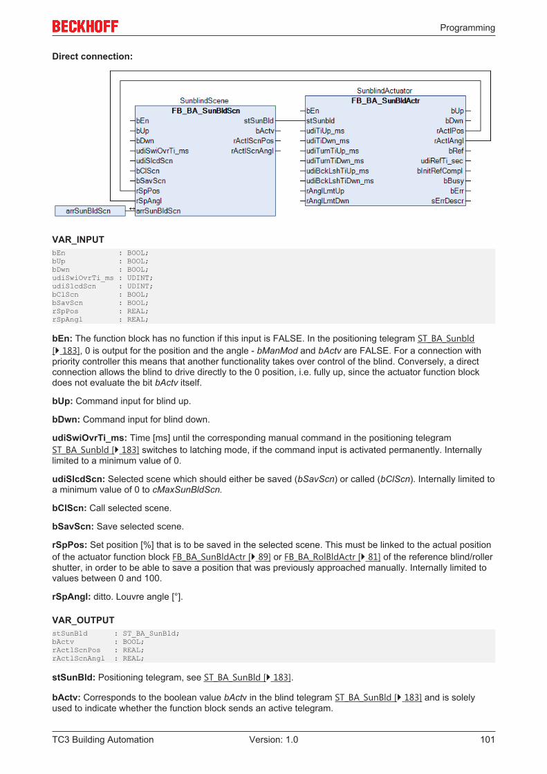
Programming
TC3 Building Automation 101Version: 1.0
Direct connection:
VAR_INPUTbEn : BOOL;bUp : BOOL;bDwn : BOOL;udiSwiOvrTi_ms : UDINT;udiSlcdScn : UDINT;bClScn : BOOL;bSavScn : BOOL;rSpPos : REAL;rSpAngl : REAL;
bEn: The function block has no function if this input is FALSE. In the positioning telegram ST_BA_Sunbld[} 183], 0 is output for the position and the angle - bManMod and bActv are FALSE. For a connection withpriority controller this means that another functionality takes over control of the blind. Conversely, a directconnection allows the blind to drive directly to the 0 position, i.e. fully up, since the actuator function blockdoes not evaluate the bit bActv itself.
bUp: Command input for blind up.
bDwn: Command input for blind down.
udiSwiOvrTi_ms: Time [ms] until the corresponding manual command in the positioning telegramST_BA_Sunbld [} 183] switches to latching mode, if the command input is activated permanently. Internallylimited to a minimum value of 0.
udiSlcdScn: Selected scene which should either be saved (bSavScn) or called (bClScn). Internally limited toa minimum value of 0 to cMaxSunBldScn.
bClScn: Call selected scene.
bSavScn: Save selected scene.
rSpPos: Set position [%] that is to be saved in the selected scene. This must be linked to the actual positionof the actuator function block FB_BA_SunBldActr [} 89] or FB_BA_RolBldActr [} 81] of the reference blind/rollershutter, in order to be able to save a position that was previously approached manually. Internally limited tovalues between 0 and 100.
rSpAngl: ditto. Louvre angle [°].
VAR_OUTPUTstSunBld : ST_BA_SunBld;bActv : BOOL;rActlScnPos : REAL;rActlScnAngl : REAL;
stSunBld: Positioning telegram, see ST_BA_SunBld [} 183].
bActv: Corresponds to the boolean value bActv in the blind telegram ST_BA_SunBld [} 183] and is solelyused to indicate whether the function block sends an active telegram.
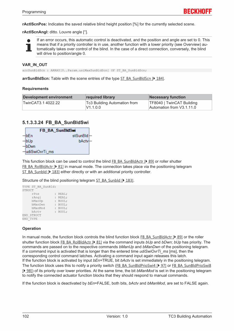
Programming
TC3 Building Automation102 Version: 1.0
rActlScnPos: Indicates the saved relative blind height position [%] for the currently selected scene.
rActlScnAngl: ditto. Louvre angle [°].
If an error occurs, this automatic control is deactivated, and the position and angle are set to 0. Thismeans that if a priority controller is in use, another function with a lower priority (see Overview) au-tomatically takes over control of the blind. In the case of a direct connection, conversely, the blindwill drive to position/angle 0.
VAR_IN_OUTarrSunBldScn : ARRAY[0..Param.usiMaxSunBldScn] OF ST_BA_SunBldScn;
arrSunBldScn: Table with the scene entries of the type ST_BA_SunBldScn [} 184].
Requirements
Development environment required library Necessary functionTwinCAT3.1 4022.22 Tc3 Building Automation from
V1.1.0.0TF8040 | TwinCAT BuildingAutomation from V3.1.11.0
5.1.3.3.24 FB_BA_SunBldSwi
This function block can be used to control the blind FB_BA_SunBldActr [} 89] or roller shutterFB_BA_RolBldActr [} 81] in manual mode. The connection takes place via the positioning telegramST_BA_Sunbld [} 183] either directly or with an additional priority controller.
Structure of the blind positioning telegram ST_BA_Sunbld [} 183].TYPE ST_BA_SunBld:STRUCT rPos : REAL; rAngl : REAL; bManUp : BOOL; bManDwn : BOOL; bManMod : BOOL; bActv : BOOL;END_STRUCTEND_TYPE
Operation
In manual mode, the function block controls the blind function block FB_BA_SunBldActr [} 89] or the rollershutter function block FB_BA_RolBldActr [} 81] via the command inputs bUp and bDwn; bUp has priority. Thecommands are passed on to the respective commands bManUp and bManDwn of the positioning telegram.If a command input is activated that is longer than the entered time udiSwiOvrTi_ms [ms], then thecorresponding control command latches. Activating a command input again releases this latch.If the function block is activated by input bEn=TRUE, bit bActv is set immediately in the positioning telegram.The function block uses this to notify a priority switch (FB_BA_SunBldPrioSwi4 [} 97] or FB_BA_SunBldPrioSwi8[} 98]) of its priority over lower priorities. At the same time, the bit bManMod is set in the positioning telegramto notify the connected actuator function blocks that they should respond to manual commands.
If the function block is deactivated by bEn=FALSE, both bits, bActv and bManMod, are set to FALSE again.
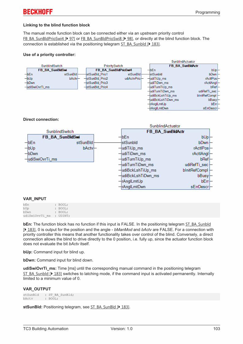
Programming
TC3 Building Automation 103Version: 1.0
Linking to the blind function block
The manual mode function block can be connected either via an upstream priority controlFB_BA_SunBldPrioSwi4 [} 97] or FB_BA_SunBldPrioSwi8 [} 98], or directly at the blind function block. Theconnection is established via the positioning telegram ST_BA_Sunbld [} 183].
Use of a priority controller:
Direct connection:
VAR_INPUTbEn : BOOL;bUp : BOOL;bDwn : BOOL;udiSwiOvrTi_ms : UDINT;
bEn: The function block has no function if this input is FALSE. In the positioning telegram ST_BA_Sunbld[} 183], 0 is output for the position and the angle - bManMod and bActv are FALSE. For a connection withpriority controller this means that another functionality takes over control of the blind. Conversely, a directconnection allows the blind to drive directly to the 0 position, i.e. fully up, since the actuator function blockdoes not evaluate the bit bActv itself.
bUp: Command input for blind up.
bDwn: Command input for blind down.
udiSwiOvrTi_ms: Time [ms] until the corresponding manual command in the positioning telegramST_BA_Sunbld [} 183] switches to latching mode, if the command input is activated permanently. Internallylimited to a minimum value of 0.
VAR_OUTPUTstSunBld : ST_BA_SunBld;bActv : BOOL;
stSunBld: Positioning telegram, see ST_BA_SunBld [} 183].
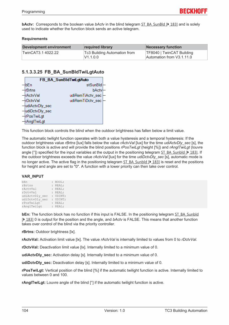
Programming
TC3 Building Automation104 Version: 1.0
bActv: Corresponds to the boolean value bActv in the blind telegram ST_BA_SunBld [} 183] and is solelyused to indicate whether the function block sends an active telegram.
Requirements
Development environment required library Necessary functionTwinCAT3.1 4022.22 Tc3 Building Automation from
V1.1.0.0TF8040 | TwinCAT BuildingAutomation from V3.1.11.0
5.1.3.3.25 FB_BA_SunBldTwiLgtAuto
This function block controls the blind when the outdoor brightness has fallen below a limit value.
The automatic twilight function operates with both a value hysteresis and a temporal hysteresis: If theoutdoor brightness value rBrtns [lux] falls below the value rActvVal [lux] for the time udiActvDly_sec [s], thefunction block is active and will provide the blind positions rPosTwiLgt (height [%]) and rAnglTwiLgt (louvreangle [°]) specified for the input variables at the output in the positioning telegram ST_BA_Sunbld [} 183]. Ifthe outdoor brightness exceeds the value rActvVal [lux] for the time udiDctvDly_sec [s], automatic mode isno longer active. The active flag in the positioning telegram ST_BA_Sunbld [} 183] is reset and the positionsfor height and angle are set to "0". A function with a lower priority can then take over control.
VAR_INPUTbEn : BOOL;rBrtns : REAL;rActvVal : REAL;rDctvVal : REAL;udiActvDly_sec : UDINT;udiDctvDly_sec : UDINT;rPosTwiLgt : REAL; rAnglTwiLgt : REAL;
bEn: The function block has no function if this input is FALSE. In the positioning telegram ST_BA_Sunbld[} 183] 0 is output for the position and the angle, and bActv is FALSE. This means that another functiontakes over control of the blind via the priority controller.
rBrtns: Outdoor brightness [lx].
rActvVal: Activation limit value [lx]. The value rActvVal is internally limited to values from 0 to rDctvVal.
rDctvVal: Deactivation limit value [lx]. Internally limited to a minimum value of 0.
udiActvDly_sec: Activation delay [s]. Internally limited to a minimum value of 0.
udiDctvDly_sec: Deactivation delay [s]. Internally limited to a minimum value of 0.
rPosTwiLgt: Vertical position of the blind [%] if the automatic twilight function is active. Internally limited tovalues between 0 and 100.
rAnglTwiLgt: Louvre angle of the blind [°] if the automatic twilight function is active.
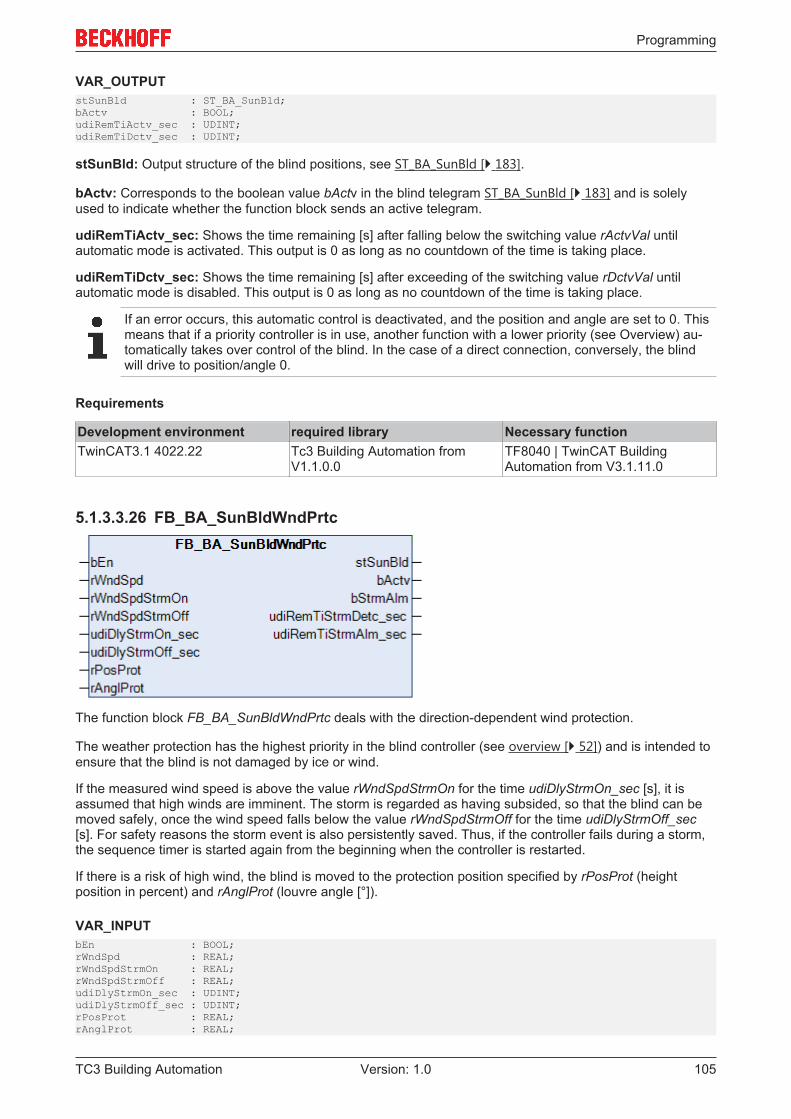
Programming
TC3 Building Automation 105Version: 1.0
VAR_OUTPUTstSunBld : ST_BA_SunBld;bActv : BOOL;udiRemTiActv_sec : UDINT;udiRemTiDctv_sec : UDINT;
stSunBld: Output structure of the blind positions, see ST_BA_SunBld [} 183].
bActv: Corresponds to the boolean value bActv in the blind telegram ST_BA_SunBld [} 183] and is solelyused to indicate whether the function block sends an active telegram.
udiRemTiActv_sec: Shows the time remaining [s] after falling below the switching value rActvVal untilautomatic mode is activated. This output is 0 as long as no countdown of the time is taking place.
udiRemTiDctv_sec: Shows the time remaining [s] after exceeding of the switching value rDctvVal untilautomatic mode is disabled. This output is 0 as long as no countdown of the time is taking place.
If an error occurs, this automatic control is deactivated, and the position and angle are set to 0. Thismeans that if a priority controller is in use, another function with a lower priority (see Overview) au-tomatically takes over control of the blind. In the case of a direct connection, conversely, the blindwill drive to position/angle 0.
Requirements
Development environment required library Necessary functionTwinCAT3.1 4022.22 Tc3 Building Automation from
V1.1.0.0TF8040 | TwinCAT BuildingAutomation from V3.1.11.0
5.1.3.3.26 FB_BA_SunBldWndPrtc
The function block FB_BA_SunBldWndPrtc deals with the direction-dependent wind protection.
The weather protection has the highest priority in the blind controller (see overview [} 52]) and is intended toensure that the blind is not damaged by ice or wind.
If the measured wind speed is above the value rWndSpdStrmOn for the time udiDlyStrmOn_sec [s], it isassumed that high winds are imminent. The storm is regarded as having subsided, so that the blind can bemoved safely, once the wind speed falls below the value rWndSpdStrmOff for the time udiDlyStrmOff_sec[s]. For safety reasons the storm event is also persistently saved. Thus, if the controller fails during a storm,the sequence timer is started again from the beginning when the controller is restarted.
If there is a risk of high wind, the blind is moved to the protection position specified by rPosProt (heightposition in percent) and rAnglProt (louvre angle [°]).
VAR_INPUTbEn : BOOL;rWndSpd : REAL;rWndSpdStrmOn : REAL;rWndSpdStrmOff : REAL;udiDlyStrmOn_sec : UDINT;udiDlyStrmOff_sec : UDINT;rPosProt : REAL;rAnglProt : REAL;
Programming
TC3 Building Automation106 Version: 1.0
bEn: The function block has no function if this input is FALSE. In the positioning telegram ST_BA_Sunbld[} 183] 0 is output for the position and the angle, and bActv is FALSE. This means that another functiontakes over control of the blind via the priority controller.
rWndSpd: Wind speed. The unit of entry is arbitrary, but it is important that no value is smaller than 0 andthat the values become larger with increasing speed.
rWndSpdStrmOn: Wind speed limit value for the activation of the storm alarm. This value may be notsmaller than 0 and must lie above the value for the deactivation. Otherwise an error is output. The unit ofentry must be the same as that of the input rWndSpd. A value greater than this limit value triggers the alarmafter the specified time udiDlyStrmOn_sec.
rWndSpdStrmOff: Wind speed limit value for the deactivation of the storm alarm. This value may be notsmaller than 0 and must lie below the value for the activation. Otherwise an error is output. The unit of entrymust be the same as that of the input rWndSpd. A value smaller than or equal to this limit value resets thealarm after the specified time udiDlyStrmOff_sec.
udiDlyStrmOn_sec: Time delay until the storm alarm is triggered [s].
udiDlyStrmOff_sec: Time delay until the storm alarm is reset [s].
rPosProt: Height position of the blind [%] in the case of protection.
rAnglProt: Louvre angle of the blind [°] in the case of protection.
VAR_OUTPUTstSunBld : ST_BA_SunBld;bActv : BOOL;bStrmAlm : BOOL;udiRemTiStrmDetc_sec : UDINT;udiRemTiStrmAlm_sec : UDINT;
stSunBld: Output structure of the blind positions, see ST_BA_SunBld [} 183].
bActv: Corresponds to the boolean value bActv in the blind telegram ST_BA_SunBld [} 183] and is solelyused to indicate whether the function block sends an active telegram.
bStrmAlm: Indicates the storm alarm.
udiRemTiStrmDetc_sec: In the non-critical case, this second counter continuously shows the alarm delaytime udiDlyStrmOn_sec. If the measured wind speed rWndSpd is above the activation limit valuerWndSpdStrmOn, the seconds to the alarm are counted down. This output is 0 as long as no countdown ofthe time is taking place.
udiRemTiStrmAlm_sec: As soon as the storm alarm is initiated, this second counter initially constantlyindicates the deactivation time delay of the storm alarm udiDlyStrmOff_sec. If the measured wind speedrWndSpd falls below the deactivation limit value rWndSpdStrmOff, the seconds to the all-clear signal(bStrmAlm=FALSE) are counted down. This output is 0 as long as no countdown of the time is taking place.
If an error occurs, this automatic control is deactivated, and the position and angle are set to 0. Thismeans that if a priority controller is in use, another function with a lower priority (see Overview) au-tomatically takes over control of the blind. In the case of a direct connection, conversely, the blindwill drive to position/angle 0.
Requirements
Development environment required library Necessary functionTwinCAT3.1 4022.22 Tc3 Building Automation from
V1.1.0.0TF8040 | TwinCAT BuildingAutomation from V3.1.11.0
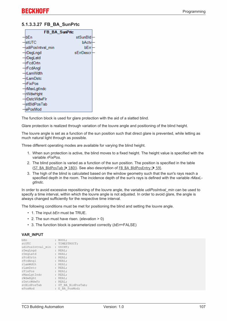
Programming
TC3 Building Automation 107Version: 1.0
5.1.3.3.27 FB_BA_SunPrtc
The function block is used for glare protection with the aid of a slatted blind.
Glare protection is realized through variation of the louvre angle and positioning of the blind height.
The louvre angle is set as a function of the sun position such that direct glare is prevented, while letting asmuch natural light through as possible.
Three different operating modes are available for varying the blind height.
1. When sun protection is active, the blind moves to a fixed height. The height value is specified with thevariable rFixPos.
2. The blind position is varied as a function of the sun position. The position is specified in the table(ST_BA_BldPosTab [} 180]). See also description of FB_BA_BldPosEntry [} 59].
3. The high of the blind is calculated based on the window geometry such that the sun's rays reach aspecified depth in the room. The incidence depth of the sun's rays is defined with the variable rMaxL-gtIndc.
In order to avoid excessive repositioning of the louvre angle, the variable udiPosIntval_min can be used tospecify a time interval, within which the louvre angle is not adjusted. In order to avoid glare, the angle isalways changed sufficiently for the respective time interval.
The following conditions must be met for positioning the blind and setting the louvre angle.
• 1. The input bEn must be TRUE.• 2. The sun must have risen. (elevation > 0)• 3. The function block is parameterized correctly (bErr=FALSE)
VAR_INPUTbEn : BOOL;stUTC : TIMESTRUCT;udiPosIntval_min : UDINT;rDegLngd : REAL;rDegLatd : REAL;rFcdOrtn : REAL;rFcdAngl : REAL;rLamWdth : REAL;rLamDstc : REAL;rFixPos : REAL;rMaxLgtIndc : REAL;rWdwHght : REAL;rDstcWdwFr : REAL;stBldPosTab : ST_BA_BldPosTab;ePosMod : E_BA_PosMod;
Programming
TC3 Building Automation108 Version: 1.0
bEn: If this input is set to FALSE the positioning is inactive, i.e. the active bit (bActv) is reset in thepositioning structure stSunBld of the type ST_BA_SunBld [} 183] and the function block itself remains in astandstill mode. If on the other hand the function block is activated, then the active bit is TRUE and thefunction block outputs its control values (rPos, rAngl) in the positioning structure at the appropriate times.
stUTC: Input of current time as coordinated world time (UTC - Universal Time Coordinated, previouslyreferred to as GMT, Greenwich Mean Time) (see TIMESTRUCT). The function block FB_BA_GetTime [} 112]can be used to read this time from a target system.
A jump of more than 300 seconds leads to immediate repositioning, if the blind is in the sun andglare protection is active, based on the above criteria. This functionality was added to ensure a re-producible program execution.
udiPosIntval_min: Positioning interval in minutes - time between two blind position outputs. Valid range: 1min...720 min.
rDegLngd: Longitude [°]. Valid range: - 180°...180°.
rDegLatd: Latitude [°]. Valid range: - 90°...90°.
rFcdOrtn: Facade orientation [°]:
In the northern hemisphere, the following applies for the facade orientation (looking out of the window):
Line of sight Facade orientationNorth β=0°East β=90°South β=180°West β=270°
The following applies for the southern hemisphere:
Line of sight Facade orientationSouth β=0°East β=90°North β=180°West β=270°
rFcdAngl: Facade inclination [°]. See facade inclination [} 57].
rLamWdth: Width of the louvres in mm, see sketch [} 54].
rLamDstc: Louvre spacing in mm, see sketch [} 54].
rFixPos: Fixed (constant) shutter height [0..100%]. Applies if ePosMod = ePosModFix (see enumeratorE_BA_PosMod [} 179]).
rMaxLgtIndc: Maximum desired light incidence in mm measured from the outside of the wall (see Sunprotection: Basic principles and definitions [} 56]). The parameters rWdwHght and rDstcWdwFlr are used tocalculate how high the blinds must be, depending on the position of the sun, such that the incidence of lightdoes not exceed the value rMaxLgtIndc. Applies if ePosMod = ePosModeMaxIncidence (see enumeratorE_BA_PosMod [} 179]).
rWdwHght: Window height in mm for the calculation of the shutter height if the mode "maximum desiredincidence of light" is selected.
rDstcWdwFlr: Distance between the floor and the window sill in mm for the calculation of the shutter heightif the mode "maximum desired incidence of light" is selected.
Programming
TC3 Building Automation 109Version: 1.0
stBldPosTab: Table of 6 interpolation points, 4 of which are parameterizable, from which a blind position isthen given in relation to the position of the sun by linear interpolation. Applies if ePosMod = ePosModFix(see enumerator E_BA_PosMod [} 179]). For a more detailed description please refer to FB_BA_BldPosEntry[} 59].
ePosMod: Selection of the positioning mode, see enumerator E_BA_PosMod [} 179].
VAR_OUTPUTstSunBld : ST_BA_SunBld;bActv : BOOL;bErr : BOOL;sErrorDescr : T_MAXSTRING;
stSunBld: Output structure of the blind positions, see ST_BA_SunBld [} 183]
bActv: The function block is in active state, i.e. no error is pending, the function block is enabled, and thesun position is in the specified facade area (the facade is sunlit).
bErr: This output is switched to TRUE if the parameters entered are erroneous.
sErrDescr: Contains the error description.
Error description01: Error: The duration of the positioning interval is less than or equal to zero, or it exceeds 720 min.02: Error: The longitude entered is not within the valid range from -180°..180°.03: Error: The latitude entered is not within the valid range from -90°..90°.04: Error: The value entered for the facade inclination rFcdAngl is outside the valid range of -90°..90°.05: Error: The value for the louvre spacing (rLamDstc) is greater than or equal to the value for the louvrewidth (rLamWdth). This does not represent a "valid" blind, since the louvres cannot close fully.Mathematically, this would lead to errors.06: Error: The value entered for the louvre width rLamWdth is zero.07: Error: The value entered for the louvre spacing rLamDstc is zero.08: Error: The value entered for the fixed blind height (rFixPos) is greater than 100 or less than 0. At thesame time, "fixed blind height" positioning is selected - ePosMod=ePosModFix.09: Error: The bit "values valid" (bVld) in the positioning table stBldPosTab is not set - invalid values: seeFB_BA_BldPosEntry. At the same time, "Table" positioning is selected - ePosMod=ePosModTab.10: Error: The value entered for the maximum required light incidence rMaxLgtIndc is less than or equal tozero. At the same time, "maximum light incidence" is selected - ePosMod=ePosModMaxIndc.11: Error: The value entered for the window height rWdwHght is less than or equal to zero. At the sametime, "maximum light incidence" is selected - ePosMod=ePosModMaxIndc.12: Error: The distance between lower window edge and floor rDstcWdwFlr that was entered is less thanzero. At the same time, "maximum light incidence" is selected - ePosMod=ePosModMaxIndc.13: Error: An invalid positioning mode is entered at input ePosMod.
If an error occurs, this automatic control is deactivated, and the position and angle are set to 0. Thismeans that if a priority controller is in use, another function with a lower priority (see Overview) au-tomatically takes over control of the blind. In the case of a direct connection, conversely, the blindwill drive to position/angle 0.
Requirements
Development environment required library Necessary functionTwinCAT3.1 4022.22 Tc3 Building Automation from
V1.1.0.0TF8040 | TwinCAT BuildingAutomation from V3.1.11.0
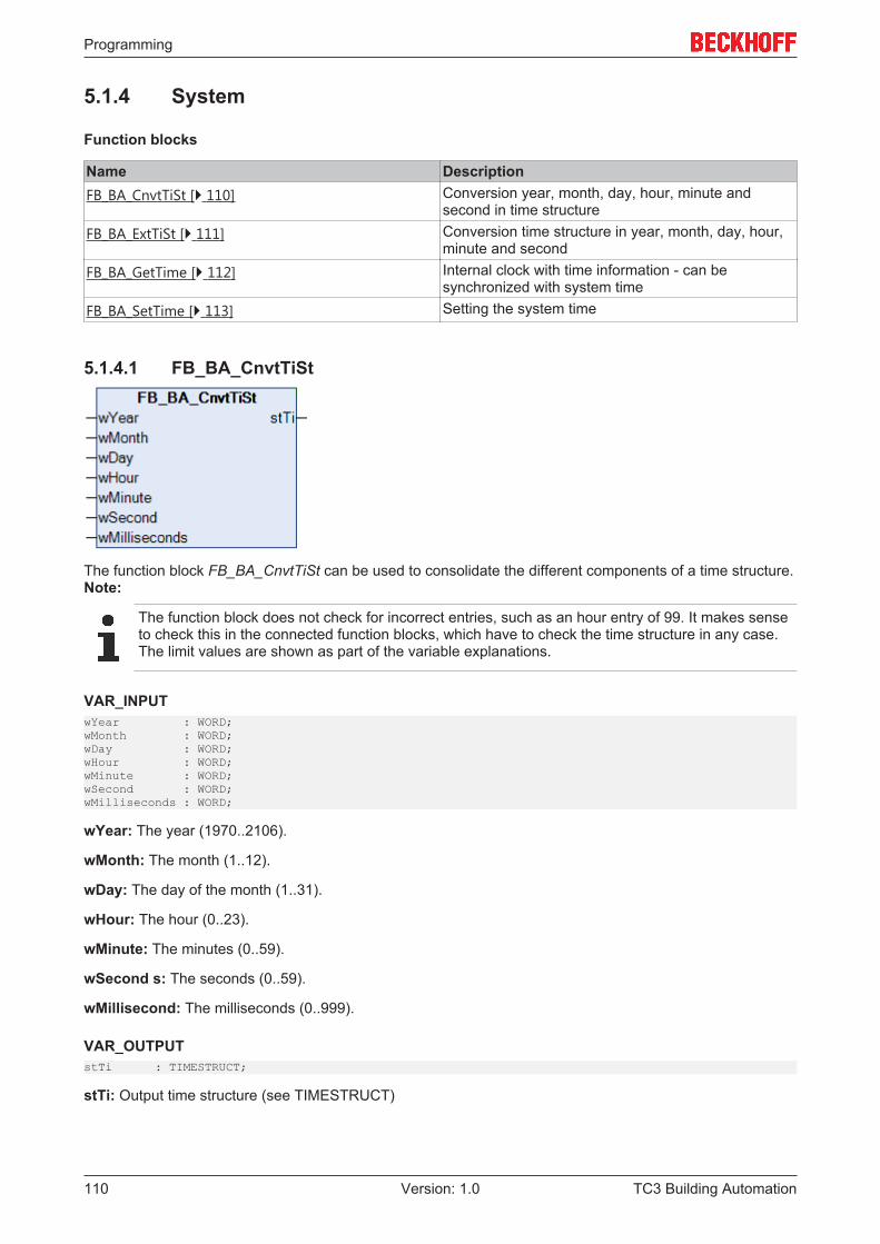
Programming
TC3 Building Automation110 Version: 1.0
5.1.4 System
Function blocks
Name DescriptionFB_BA_CnvtTiSt [} 110] Conversion year, month, day, hour, minute and
second in time structureFB_BA_ExtTiSt [} 111] Conversion time structure in year, month, day, hour,
minute and secondFB_BA_GetTime [} 112] Internal clock with time information - can be
synchronized with system timeFB_BA_SetTime [} 113] Setting the system time
5.1.4.1 FB_BA_CnvtTiSt
The function block FB_BA_CnvtTiSt can be used to consolidate the different components of a time structure.Note:
The function block does not check for incorrect entries, such as an hour entry of 99. It makes senseto check this in the connected function blocks, which have to check the time structure in any case.The limit values are shown as part of the variable explanations.
VAR_INPUTwYear : WORD;wMonth : WORD;wDay : WORD;wHour : WORD;wMinute : WORD;wSecond : WORD;wMilliseconds : WORD;
wYear: The year (1970..2106).
wMonth: The month (1..12).
wDay: The day of the month (1..31).
wHour: The hour (0..23).
wMinute: The minutes (0..59).
wSecond s: The seconds (0..59).
wMillisecond: The milliseconds (0..999).
VAR_OUTPUTstTi : TIMESTRUCT;
stTi: Output time structure (see TIMESTRUCT)
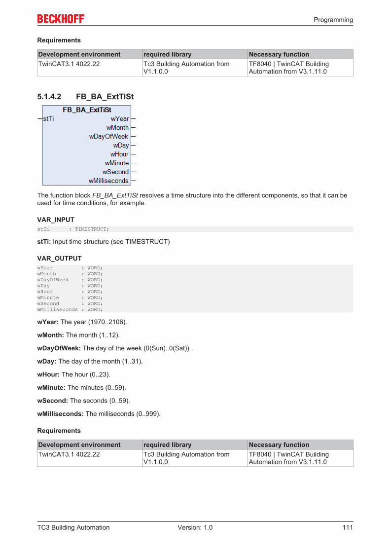
Programming
TC3 Building Automation 111Version: 1.0
Requirements
Development environment required library Necessary functionTwinCAT3.1 4022.22 Tc3 Building Automation from
V1.1.0.0TF8040 | TwinCAT BuildingAutomation from V3.1.11.0
5.1.4.2 FB_BA_ExtTiSt
The function block FB_BA_ExtTiSt resolves a time structure into the different components, so that it can beused for time conditions, for example.
VAR_INPUTstTi : TIMESTRUCT;
stTi: Input time structure (see TIMESTRUCT)
VAR_OUTPUTwYear : WORD;wMonth : WORD;wDayOfWeek : WORD;wDay : WORD;wHour : WORD;wMinute : WORD;wSecond : WORD;wMilliseconds : WORD;
wYear: The year (1970..2106).
wMonth: The month (1..12).
wDayOfWeek: The day of the week (0(Sun)..0(Sat)).
wDay: The day of the month (1..31).
wHour: The hour (0..23).
wMinute: The minutes (0..59).
wSecond: The seconds (0..59).
wMilliseconds: The milliseconds (0..999).
Requirements
Development environment required library Necessary functionTwinCAT3.1 4022.22 Tc3 Building Automation from
V1.1.0.0TF8040 | TwinCAT BuildingAutomation from V3.1.11.0
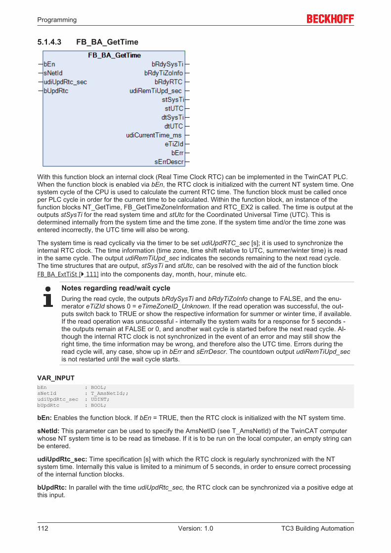
Programming
TC3 Building Automation112 Version: 1.0
5.1.4.3 FB_BA_GetTime
With this function block an internal clock (Real Time Clock RTC) can be implemented in the TwinCAT PLC.When the function block is enabled via bEn, the RTC clock is initialized with the current NT system time. Onesystem cycle of the CPU is used to calculate the current RTC time. The function block must be called onceper PLC cycle in order for the current time to be calculated. Within the function block, an instance of thefunction blocks NT_GetTime, FB_GetTimeZoneInformation and RTC_EX2 is called. The time is output at theoutputs stSysTi for the read system time and stUtc for the Coordinated Universal Time (UTC). This isdetermined internally from the system time and the time zone. If the system time and/or the time zone wasentered incorrectly, the UTC time will also be wrong.
The system time is read cyclically via the timer to be set udiUpdRTC_sec [s]; it is used to synchronize theinternal RTC clock. The time information (time zone, time shift relative to UTC, summer/winter time) is readin the same cycle. The output udiRemTiUpd_sec indicates the seconds remaining to the next read cycle.The time structures that are output, stSysTi and stUtc, can be resolved with the aid of the function blockFB_BA_ExtTiSt [} 111] into the components day, month, hour, minute etc.
Notes regarding read/wait cycleDuring the read cycle, the outputs bRdySysTi and bRdyTiZoInfo change to FALSE, and the enu-merator eTiZId shows 0 = eTimeZoneID_Unknown. If the read operation was successful, the out-puts switch back to TRUE or show the respective information for summer or winter time, if available.If the read operation was unsuccessful - internally the system waits for a response for 5 seconds -the outputs remain at FALSE or 0, and another wait cycle is started before the next read cycle. Al-though the internal RTC clock is not synchronized in the event of an error and may still show theright time, the time information may be wrong, and therefore also the UTC time. Errors during theread cycle will, any case, show up in bErr and sErrDescr. The countdown output udiRemTiUpd_secis not restarted until the wait cycle starts.
VAR_INPUTbEn : BOOL;sNetId : T_AmsNetId;;udiUpdRtc_sec : UDINT;bUpdRtc : BOOL;
bEn: Enables the function block. If bEn = TRUE, then the RTC clock is initialized with the NT system time.
sNetId: This parameter can be used to specify the AmsNetID (see T_AmsNetId) of the TwinCAT computerwhose NT system time is to be read as timebase. If it is to be run on the local computer, an empty string canbe entered.
udiUpdRtc_sec: Time specification [s] with which the RTC clock is regularly synchronized with the NTsystem time. Internally this value is limited to a minimum of 5 seconds, in order to ensure correct processingof the internal function blocks.
bUpdRtc: In parallel with the time udiUpdRtc_sec, the RTC clock can be synchronized via a positive edge atthis input.
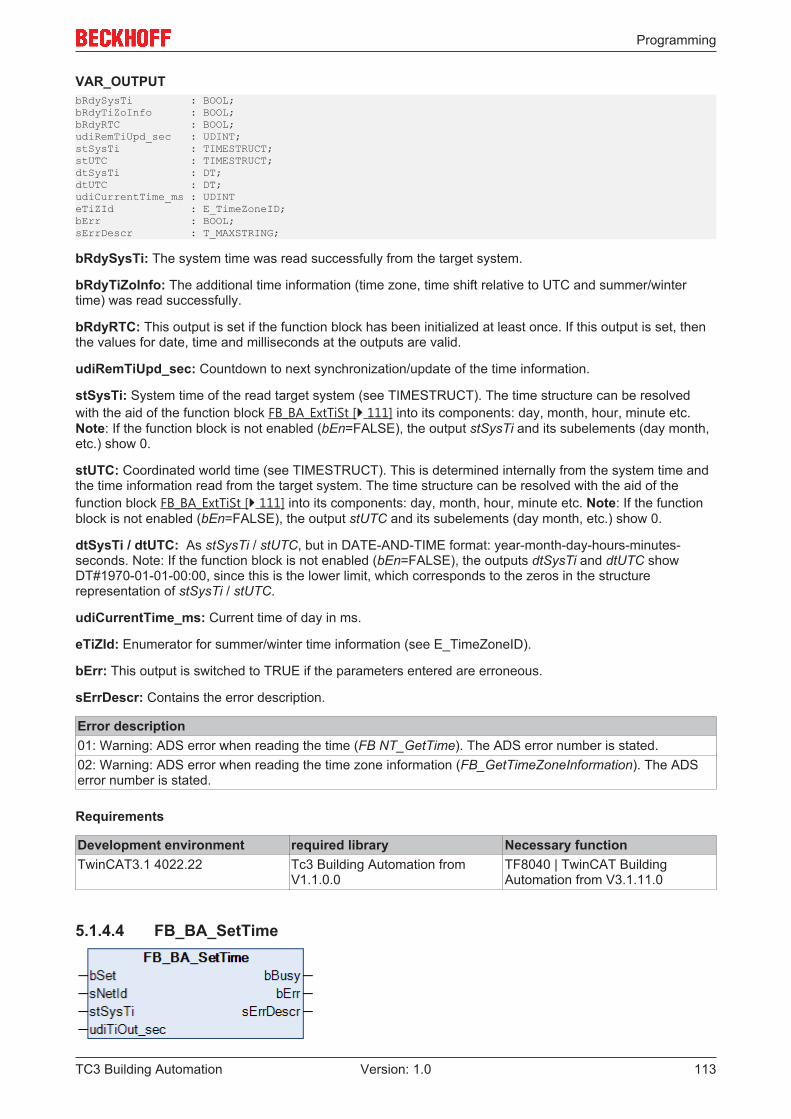
Programming
TC3 Building Automation 113Version: 1.0
VAR_OUTPUTbRdySysTi : BOOL;bRdyTiZoInfo : BOOL;bRdyRTC : BOOL;udiRemTiUpd_sec : UDINT;stSysTi : TIMESTRUCT;stUTC : TIMESTRUCT;dtSysTi : DT;dtUTC : DT;udiCurrentTime_ms : UDINTeTiZId : E_TimeZoneID;bErr : BOOL;sErrDescr : T_MAXSTRING;
bRdySysTi: The system time was read successfully from the target system.
bRdyTiZoInfo: The additional time information (time zone, time shift relative to UTC and summer/wintertime) was read successfully.
bRdyRTC: This output is set if the function block has been initialized at least once. If this output is set, thenthe values for date, time and milliseconds at the outputs are valid.
udiRemTiUpd_sec: Countdown to next synchronization/update of the time information.
stSysTi: System time of the read target system (see TIMESTRUCT). The time structure can be resolvedwith the aid of the function block FB_BA_ExtTiSt [} 111] into its components: day, month, hour, minute etc.Note: If the function block is not enabled (bEn=FALSE), the output stSysTi and its subelements (day month,etc.) show 0.
stUTC: Coordinated world time (see TIMESTRUCT). This is determined internally from the system time andthe time information read from the target system. The time structure can be resolved with the aid of thefunction block FB_BA_ExtTiSt [} 111] into its components: day, month, hour, minute etc. Note: If the functionblock is not enabled (bEn=FALSE), the output stUTC and its subelements (day month, etc.) show 0.
dtSysTi / dtUTC: As stSysTi / stUTC, but in DATE-AND-TIME format: year-month-day-hours-minutes-seconds. Note: If the function block is not enabled (bEn=FALSE), the outputs dtSysTi and dtUTC showDT#1970-01-01-00:00, since this is the lower limit, which corresponds to the zeros in the structurerepresentation of stSysTi / stUTC.
udiCurrentTime_ms: Current time of day in ms.
eTiZId: Enumerator for summer/winter time information (see E_TimeZoneID).
bErr: This output is switched to TRUE if the parameters entered are erroneous.
sErrDescr: Contains the error description.
Error description01: Warning: ADS error when reading the time (FB NT_GetTime). The ADS error number is stated.02: Warning: ADS error when reading the time zone information (FB_GetTimeZoneInformation). The ADSerror number is stated.
Requirements
Development environment required library Necessary functionTwinCAT3.1 4022.22 Tc3 Building Automation from
V1.1.0.0TF8040 | TwinCAT BuildingAutomation from V3.1.11.0
5.1.4.4 FB_BA_SetTime
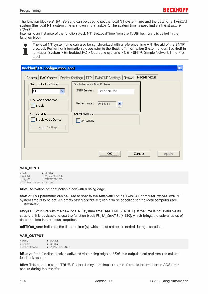
Programming
TC3 Building Automation114 Version: 1.0
The function block FB_BA_SetTime can be used to set the local NT system time and the date for a TwinCATsystem (the local NT system time is shown in the taskbar). The system time is specified via the structurestSysTi.Internally, an instance of the function block NT_SetLocalTime from the TcUtilities library is called in thefunction block.
The local NT system time can also be synchronized with a reference time with the aid of the SNTPprotocol. For further information please refer to the Beckhoff Information System under: Beckhoff In-formation System > Embedded-PC > Operating systems > CE > SNTP: Simple Network Time Pro-tocol
VAR_INPUTbSet : BOOL;sNetId : T_AmsNetId;stSysTi : TIMESTRUCT;udiTiOut_sec : UDINT;
bSet: Activation of the function block with a rising edge.
sNetId: This parameter can be used to specify the AmsNetID of the TwinCAT computer, whose local NTsystem time is to be set. An empty string sNetId := ''; can also be specified for the local computer (seeT_AmsNetId).
stSysTi: Structure with the new local NT system time (see TIMESTRUCT). If the time is not available asstructure, it is advisable to use the function block FB_BA_CnvtTiSt [} 110], which brings the subvariables ofdate and time in a structure together.
udiTiOut_sec: Indicates the timeout time [s], which must not be exceeded during execution.
VAR_OUTPUTbBusy : BOOL;bError : BOOL;sErrorDescr : T_MAXSTRING;
bBusy: If the function block is activated via a rising edge at bSet, this output is set and remains set untilfeedback occurs.
bErr: This output is set to TRUE, if either the system time to be transferred is incorrect or an ADS erroroccurs during the transfer.
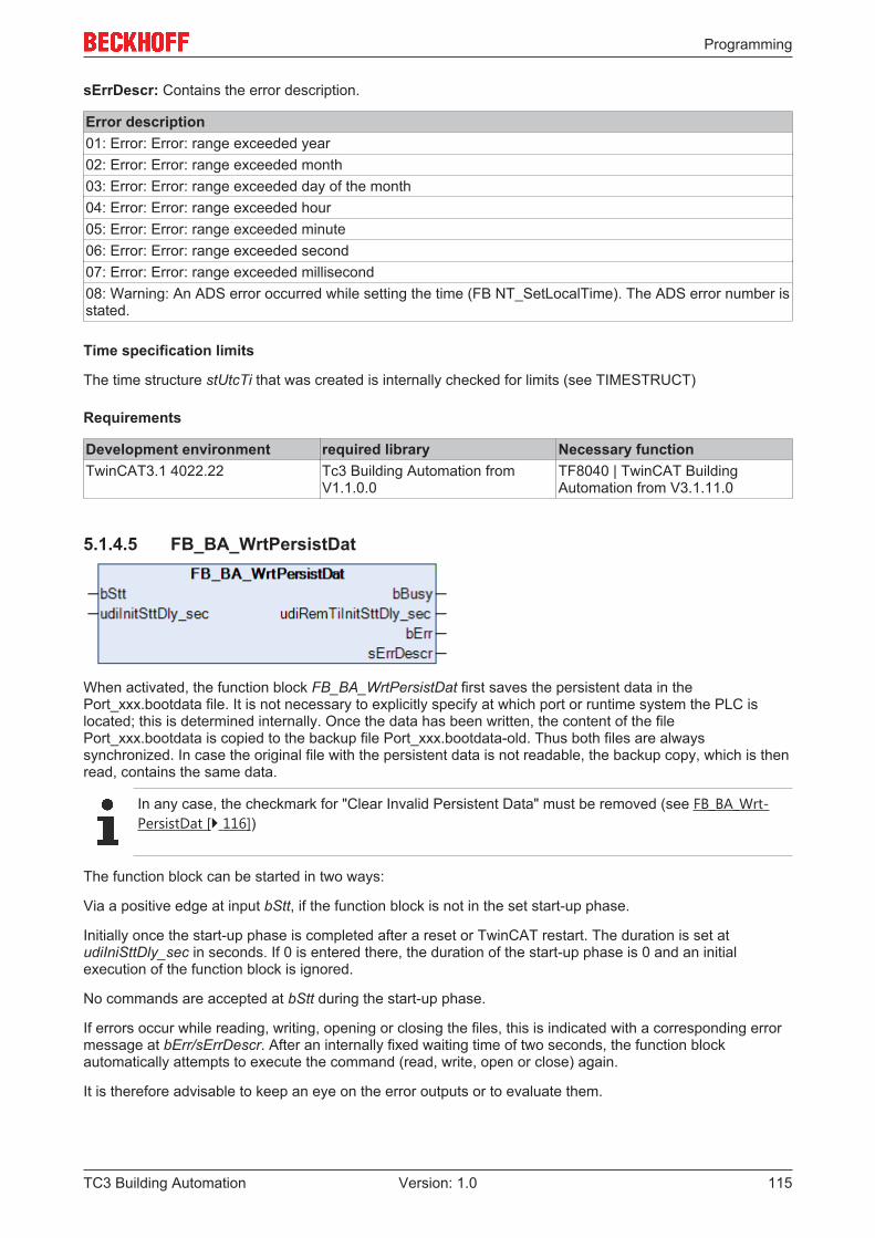
Programming
TC3 Building Automation 115Version: 1.0
sErrDescr: Contains the error description.
Error description01: Error: Error: range exceeded year02: Error: Error: range exceeded month03: Error: Error: range exceeded day of the month04: Error: Error: range exceeded hour05: Error: Error: range exceeded minute06: Error: Error: range exceeded second07: Error: Error: range exceeded millisecond08: Warning: An ADS error occurred while setting the time (FB NT_SetLocalTime). The ADS error number isstated.
Time specification limits
The time structure stUtcTi that was created is internally checked for limits (see TIMESTRUCT)
Requirements
Development environment required library Necessary functionTwinCAT3.1 4022.22 Tc3 Building Automation from
V1.1.0.0TF8040 | TwinCAT BuildingAutomation from V3.1.11.0
5.1.4.5 FB_BA_WrtPersistDat
When activated, the function block FB_BA_WrtPersistDat first saves the persistent data in thePort_xxx.bootdata file. It is not necessary to explicitly specify at which port or runtime system the PLC islocated; this is determined internally. Once the data has been written, the content of the filePort_xxx.bootdata is copied to the backup file Port_xxx.bootdata-old. Thus both files are alwayssynchronized. In case the original file with the persistent data is not readable, the backup copy, which is thenread, contains the same data.
In any case, the checkmark for "Clear Invalid Persistent Data" must be removed (see FB_BA_Wrt-PersistDat [} 116])
The function block can be started in two ways:
Via a positive edge at input bStt, if the function block is not in the set start-up phase.
Initially once the start-up phase is completed after a reset or TwinCAT restart. The duration is set atudiIniSttDly_sec in seconds. If 0 is entered there, the duration of the start-up phase is 0 and an initialexecution of the function block is ignored.
No commands are accepted at bStt during the start-up phase.
If errors occur while reading, writing, opening or closing the files, this is indicated with a corresponding errormessage at bErr/sErrDescr. After an internally fixed waiting time of two seconds, the function blockautomatically attempts to execute the command (read, write, open or close) again.
It is therefore advisable to keep an eye on the error outputs or to evaluate them.
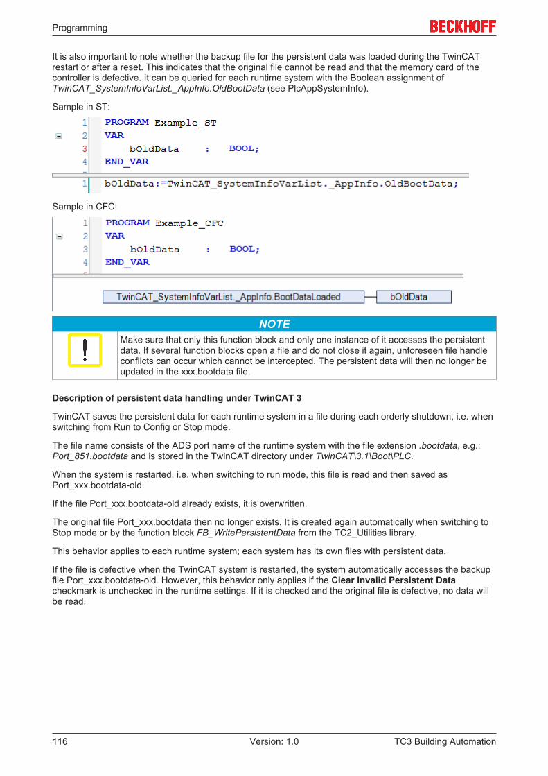
Programming
TC3 Building Automation116 Version: 1.0
It is also important to note whether the backup file for the persistent data was loaded during the TwinCATrestart or after a reset. This indicates that the original file cannot be read and that the memory card of thecontroller is defective. It can be queried for each runtime system with the Boolean assignment ofTwinCAT_SystemInfoVarList._AppInfo.OldBootData (see PlcAppSystemInfo).
Sample in ST:
Sample in CFC:
NOTEMake sure that only this function block and only one instance of it accesses the persistentdata. If several function blocks open a file and do not close it again, unforeseen file handleconflicts can occur which cannot be intercepted. The persistent data will then no longer beupdated in the xxx.bootdata file.
Description of persistent data handling under TwinCAT 3
TwinCAT saves the persistent data for each runtime system in a file during each orderly shutdown, i.e. whenswitching from Run to Config or Stop mode.
The file name consists of the ADS port name of the runtime system with the file extension .bootdata, e.g.:Port_851.bootdata and is stored in the TwinCAT directory under TwinCAT\3.1\Boot\PLC.
When the system is restarted, i.e. when switching to run mode, this file is read and then saved asPort_xxx.bootdata-old.
If the file Port_xxx.bootdata-old already exists, it is overwritten.
The original file Port_xxx.bootdata then no longer exists. It is created again automatically when switching toStop mode or by the function block FB_WritePersistentData from the TC2_Utilities library.
This behavior applies to each runtime system; each system has its own files with persistent data.
If the file is defective when the TwinCAT system is restarted, the system automatically accesses the backupfile Port_xxx.bootdata-old. However, this behavior only applies if the Clear Invalid Persistent Datacheckmark is unchecked in the runtime settings. If it is checked and the original file is defective, no data willbe read.
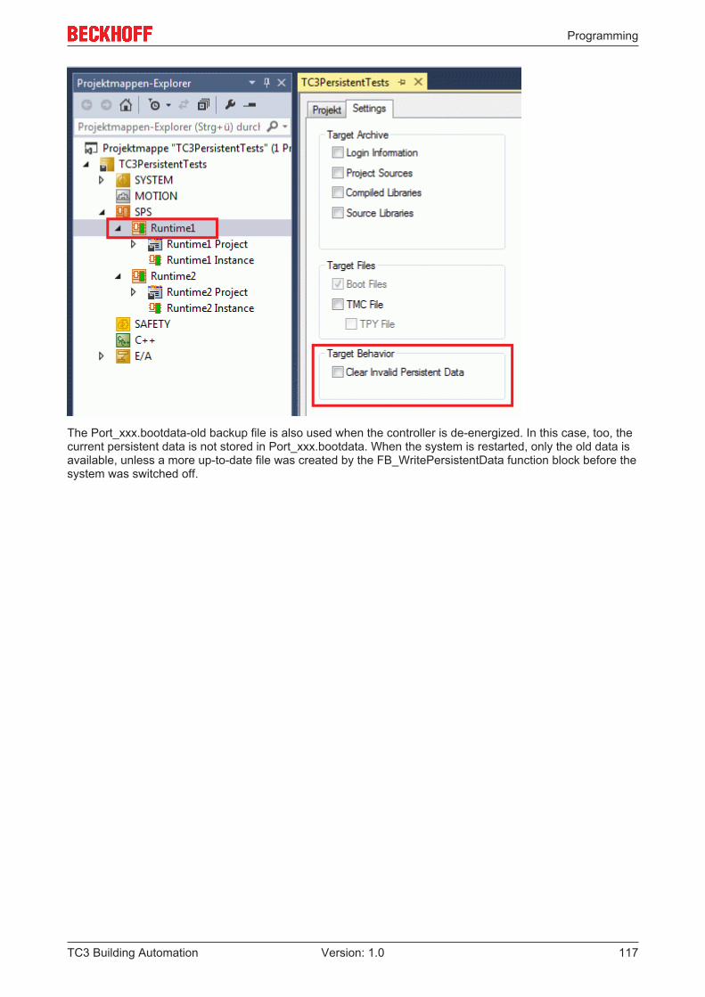
Programming
TC3 Building Automation 117Version: 1.0
The Port_xxx.bootdata-old backup file is also used when the controller is de-energized. In this case, too, thecurrent persistent data is not stored in Port_xxx.bootdata. When the system is restarted, only the old data isavailable, unless a more up-to-date file was created by the FB_WritePersistentData function block before thesystem was switched off.
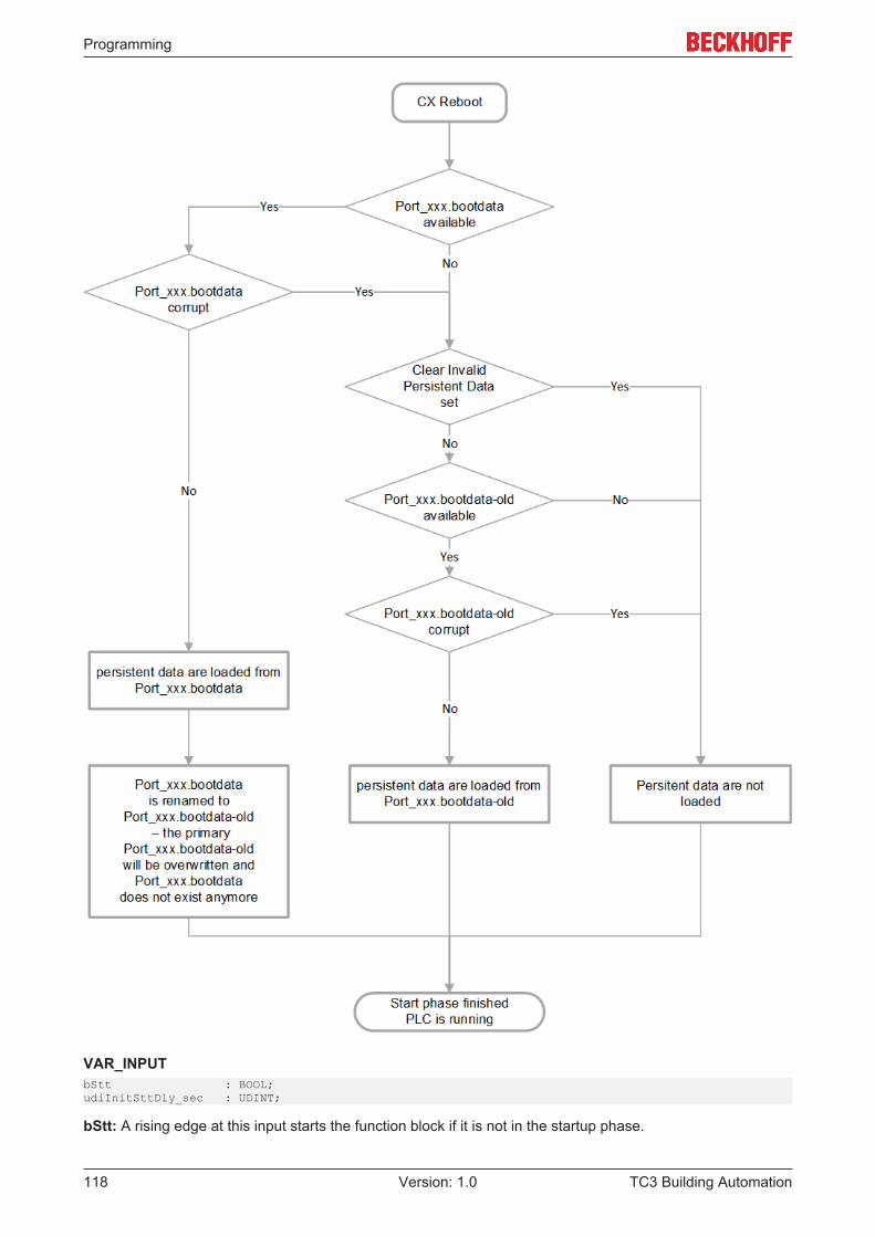
Programming
TC3 Building Automation118 Version: 1.0
VAR_INPUTbStt : BOOL;udiInitSttDly_sec : UDINT;
bStt: A rising edge at this input starts the function block if it is not in the startup phase.
Programming
TC3 Building Automation 119Version: 1.0
udiInitSttDly_sec: Startup phase after a reset or TwinCAT restart. The duration is set in seconds. Once thestartup phase has elapsed, the function block is automatically started once. No commands are accepted atbStt during the start-up phase. If "0" is set at udiIniSttDly_sec, the startup phase is skipped. This input ispreconfigured with 10 s.
VAR_OUTPUTbBusy : BOOL;udiRemTiInitSttDly_sec : UDINT;bErr : BOOL;sErrDescr : T_MaxString;
bBusy: The function block is being executed.
udiRemTiInitSttDly_sec: Countdown of the set startup phase.
bErr: This output is switched to TRUE if the parameters entered are erroneous.
sErrDescr: Contains the error description.
Error description01: Error: The number of the ADS port issued by the PLC is "0“02: Warning: Error when writing the persistent data via the internal function block FB_WritePersistentData.Additionally its error number.03: Warning: Error when opening the backup file (xxx.bootdata-old) via the internal function blockFB_FileOpen. Additionally its error number.04: Warning: Error when reading the original file (xxx.bootdata) via the internalfunction block FB_FileRead. Additionally its error number05: Warning: Error when writing to the backup file (xxx.bootdata-old) via the internal function blockFB_FileWrite. Additionally its error number.06: Warning: Error when closing the original file (xxx.bootdata) via the internal function block FB_FileClose.Additionally its error number.07: Warning: Error when closing the backup file (xxx.bootdata-old) via the internal function blockFB_FileClose. Additionally its error number.
Requirements
Development environment required library Necessary functionTwinCAT3.1 4022.22 Tc3 Building Automation from
V1.1.0.0TF8040 | TwinCAT BuildingAutomation from V3.1.11.0
5.1.5 Universal
5.1.5.1 Actuators
Function blocks
Name DescriptionFB_BA_Actuator_3Point [} 120] Control of three-point dampers or valves
FB_BA_Anlg3Pnt [} 121] Analog value for three-point converters
FB_BA_AntBlkg [} 122] Blocking protection for pump or actuators
FB_BA_Motor1St [} 123] Control of single-speed drives
FB_BA_Motor2St [} 124] Control of two-speed drives
FB_BA_PWM [} 125] Pulse width modulation function block
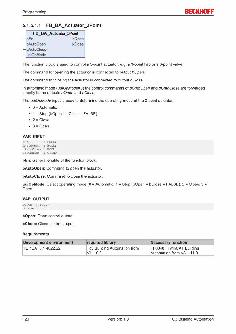
Programming
TC3 Building Automation120 Version: 1.0
5.1.5.1.1 FB_BA_Actuator_3Point
The function block is used to control a 3-point actuator, e.g. a 3-point flap or a 3-point valve.
The command for opening the actuator is connected to output bOpen.
The command for closing the actuator is connected to output bClose.
In automatic mode (udiOpMode=0) the control commands of bCmdOpen and bCmdClose are forwardeddirectly to the outputs bOpen and bClose.
The udiOpMode input is used to determine the operating mode of the 3-point actuator:
• 0 = Automatic• 1 = Stop (bOpen = bClose = FALSE)• 2 = Close• 3 = Open
VAR_INPUTbEn : BOOL;bAutoOpen : BOOL;bAutoClose : BOOL;udiOpMode : UDINT
bEn: General enable of the function block.
bAutoOpen: Command to open the actuator.
bAutoClose: Command to close the actuator.
udiOpMode: Select operating mode (0 = Automatic, 1 = Stop (bOpen = bClose = FALSE), 2 = Close, 3 =Open)
VAR_OUTPUTbOpen : BOOL;bClose : BOOL;
bOpen: Open control output.
bClose: Close control output.
Requirements
Development environment required library Necessary functionTwinCAT3.1 4022.22 Tc3 Building Automation from
V1.1.0.0TF8040 | TwinCAT BuildingAutomation from V3.1.11.0
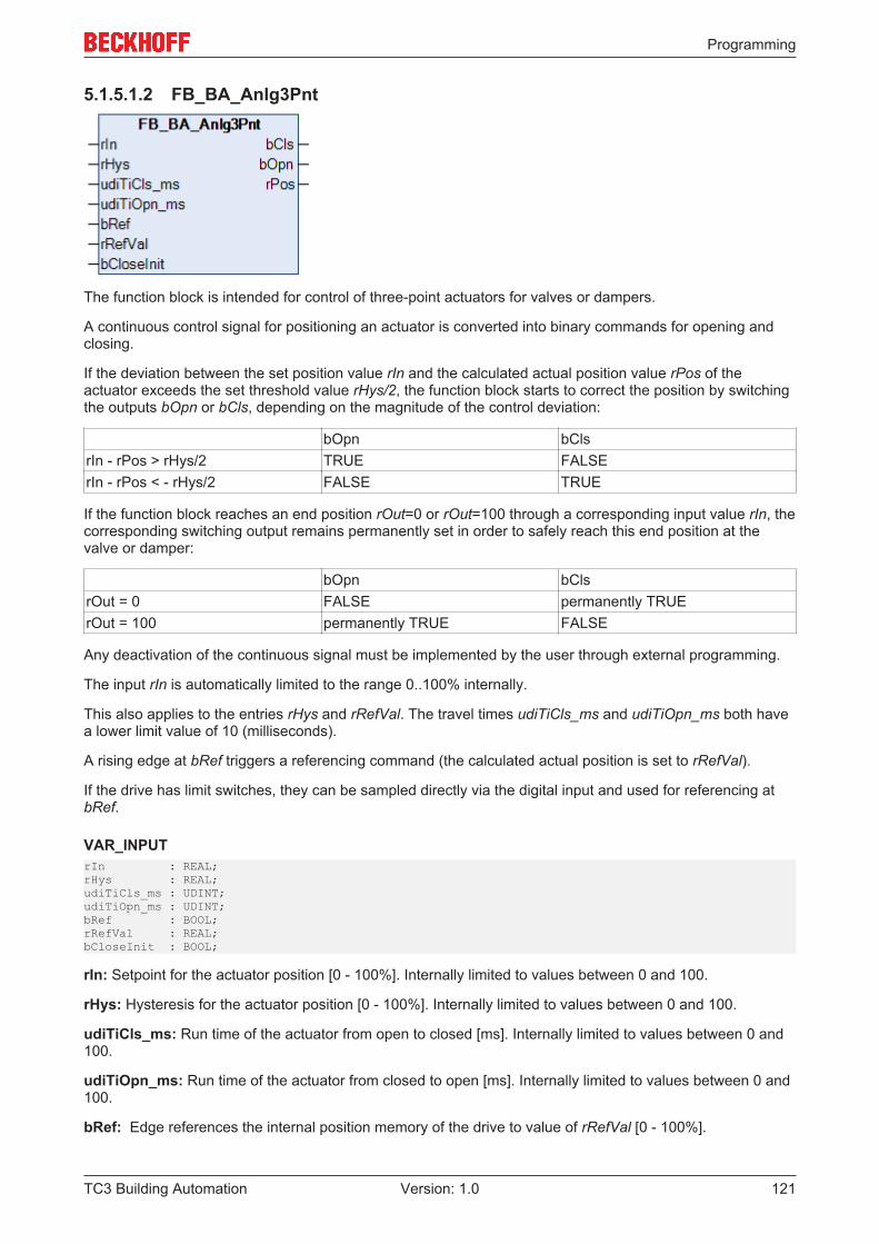
Programming
TC3 Building Automation 121Version: 1.0
5.1.5.1.2 FB_BA_Anlg3Pnt
The function block is intended for control of three-point actuators for valves or dampers.
A continuous control signal for positioning an actuator is converted into binary commands for opening andclosing.
If the deviation between the set position value rIn and the calculated actual position value rPos of theactuator exceeds the set threshold value rHys/2, the function block starts to correct the position by switchingthe outputs bOpn or bCls, depending on the magnitude of the control deviation:
bOpn bClsrIn - rPos > rHys/2 TRUE FALSErIn - rPos < - rHys/2 FALSE TRUE
If the function block reaches an end position rOut=0 or rOut=100 through a corresponding input value rIn, thecorresponding switching output remains permanently set in order to safely reach this end position at thevalve or damper:
bOpn bClsrOut = 0 FALSE permanently TRUErOut = 100 permanently TRUE FALSE
Any deactivation of the continuous signal must be implemented by the user through external programming.
The input rIn is automatically limited to the range 0..100% internally.
This also applies to the entries rHys and rRefVal. The travel times udiTiCls_ms and udiTiOpn_ms both havea lower limit value of 10 (milliseconds).
A rising edge at bRef triggers a referencing command (the calculated actual position is set to rRefVal).
If the drive has limit switches, they can be sampled directly via the digital input and used for referencing atbRef.
VAR_INPUTrIn : REAL;rHys : REAL;udiTiCls_ms : UDINT;udiTiOpn_ms : UDINT;bRef : BOOL;rRefVal : REAL;bCloseInit : BOOL;
rIn: Setpoint for the actuator position [0 - 100%]. Internally limited to values between 0 and 100.
rHys: Hysteresis for the actuator position [0 - 100%]. Internally limited to values between 0 and 100.
udiTiCls_ms: Run time of the actuator from open to closed [ms]. Internally limited to values between 0 and100.
udiTiOpn_ms: Run time of the actuator from closed to open [ms]. Internally limited to values between 0 and100.
bRef: Edge references the internal position memory of the drive to value of rRefVal [0 - 100%].
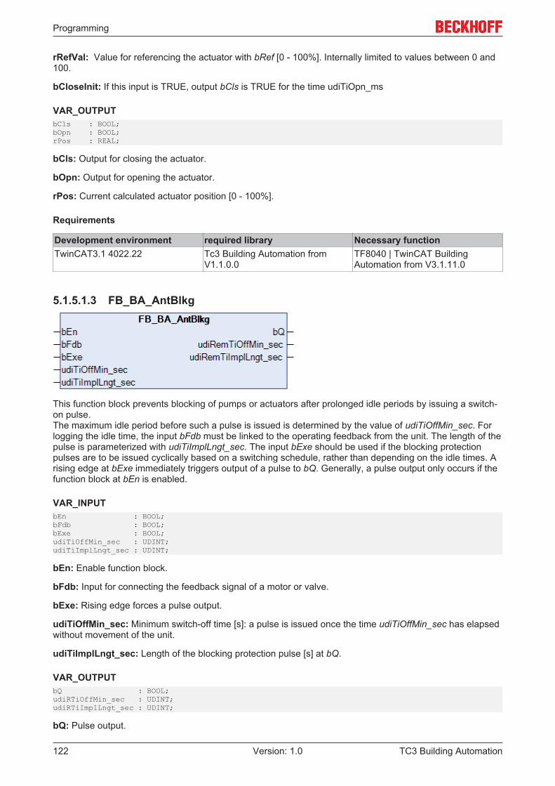
Programming
TC3 Building Automation122 Version: 1.0
rRefVal: Value for referencing the actuator with bRef [0 - 100%]. Internally limited to values between 0 and100.
bCloseInit: If this input is TRUE, output bCls is TRUE for the time udiTiOpn_ms
VAR_OUTPUTbCls : BOOL;bOpn : BOOL;rPos : REAL;
bCls: Output for closing the actuator.
bOpn: Output for opening the actuator.
rPos: Current calculated actuator position [0 - 100%].
Requirements
Development environment required library Necessary functionTwinCAT3.1 4022.22 Tc3 Building Automation from
V1.1.0.0TF8040 | TwinCAT BuildingAutomation from V3.1.11.0
5.1.5.1.3 FB_BA_AntBlkg
This function block prevents blocking of pumps or actuators after prolonged idle periods by issuing a switch-on pulse.The maximum idle period before such a pulse is issued is determined by the value of udiTiOffMin_sec. Forlogging the idle time, the input bFdb must be linked to the operating feedback from the unit. The length of thepulse is parameterized with udiTiImplLngt_sec. The input bExe should be used if the blocking protectionpulses are to be issued cyclically based on a switching schedule, rather than depending on the idle times. Arising edge at bExe immediately triggers output of a pulse to bQ. Generally, a pulse output only occurs if thefunction block at bEn is enabled.
VAR_INPUTbEn : BOOL;bFdb : BOOL;bExe : BOOL;udiTiOffMin_sec : UDINT;udiTiImplLngt_sec : UDINT;
bEn: Enable function block.
bFdb: Input for connecting the feedback signal of a motor or valve.
bExe: Rising edge forces a pulse output.
udiTiOffMin_sec: Minimum switch-off time [s]: a pulse is issued once the time udiTiOffMin_sec has elapsedwithout movement of the unit.
udiTiImplLngt_sec: Length of the blocking protection pulse [s] at bQ.
VAR_OUTPUTbQ : BOOL;udiRTiOffMin_sec : UDINT;udiRTiImplLngt_sec : UDINT;
bQ: Pulse output.
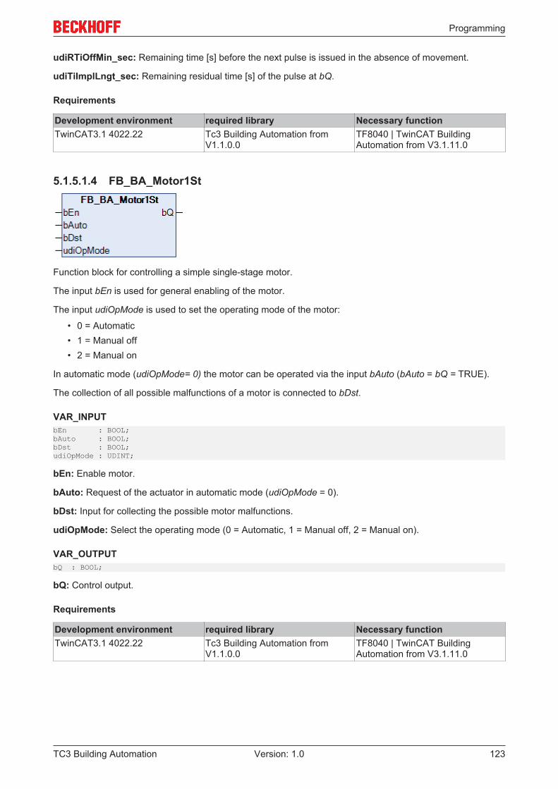
Programming
TC3 Building Automation 123Version: 1.0
udiRTiOffMin_sec: Remaining time [s] before the next pulse is issued in the absence of movement.
udiTiImplLngt_sec: Remaining residual time [s] of the pulse at bQ.
Requirements
Development environment required library Necessary functionTwinCAT3.1 4022.22 Tc3 Building Automation from
V1.1.0.0TF8040 | TwinCAT BuildingAutomation from V3.1.11.0
5.1.5.1.4 FB_BA_Motor1St
Function block for controlling a simple single-stage motor.
The input bEn is used for general enabling of the motor.
The input udiOpMode is used to set the operating mode of the motor:
• 0 = Automatic• 1 = Manual off• 2 = Manual on
In automatic mode (udiOpMode= 0) the motor can be operated via the input bAuto (bAuto = bQ = TRUE).
The collection of all possible malfunctions of a motor is connected to bDst.
VAR_INPUTbEn : BOOL;bAuto : BOOL;bDst : BOOL;udiOpMode : UDINT;
bEn: Enable motor.
bAuto: Request of the actuator in automatic mode (udiOpMode = 0).
bDst: Input for collecting the possible motor malfunctions.
udiOpMode: Select the operating mode (0 = Automatic, 1 = Manual off, 2 = Manual on).
VAR_OUTPUTbQ : BOOL;
bQ: Control output.
Requirements
Development environment required library Necessary functionTwinCAT3.1 4022.22 Tc3 Building Automation from
V1.1.0.0TF8040 | TwinCAT BuildingAutomation from V3.1.11.0
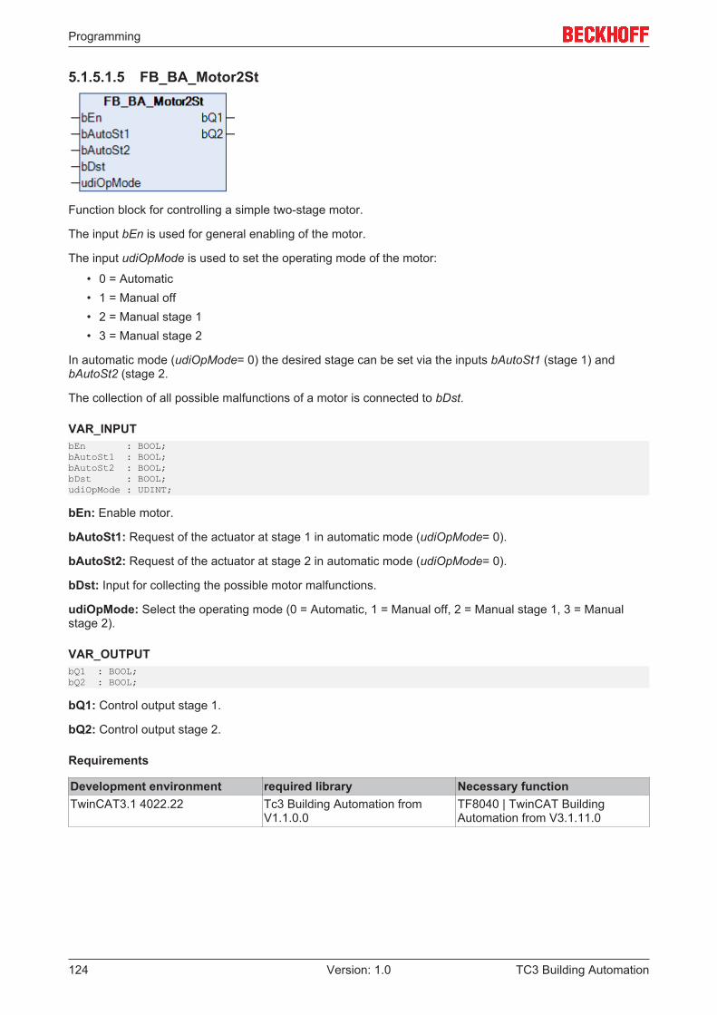
Programming
TC3 Building Automation124 Version: 1.0
5.1.5.1.5 FB_BA_Motor2St
Function block for controlling a simple two-stage motor.
The input bEn is used for general enabling of the motor.
The input udiOpMode is used to set the operating mode of the motor:
• 0 = Automatic• 1 = Manual off• 2 = Manual stage 1• 3 = Manual stage 2
In automatic mode (udiOpMode= 0) the desired stage can be set via the inputs bAutoSt1 (stage 1) andbAutoSt2 (stage 2.
The collection of all possible malfunctions of a motor is connected to bDst.
VAR_INPUTbEn : BOOL;bAutoSt1 : BOOL;bAutoSt2 : BOOL;bDst : BOOL;udiOpMode : UDINT;
bEn: Enable motor.
bAutoSt1: Request of the actuator at stage 1 in automatic mode (udiOpMode= 0).
bAutoSt2: Request of the actuator at stage 2 in automatic mode (udiOpMode= 0).
bDst: Input for collecting the possible motor malfunctions.
udiOpMode: Select the operating mode (0 = Automatic, 1 = Manual off, 2 = Manual stage 1, 3 = Manualstage 2).
VAR_OUTPUTbQ1 : BOOL;bQ2 : BOOL;
bQ1: Control output stage 1.
bQ2: Control output stage 2.
Requirements
Development environment required library Necessary functionTwinCAT3.1 4022.22 Tc3 Building Automation from
V1.1.0.0TF8040 | TwinCAT BuildingAutomation from V3.1.11.0
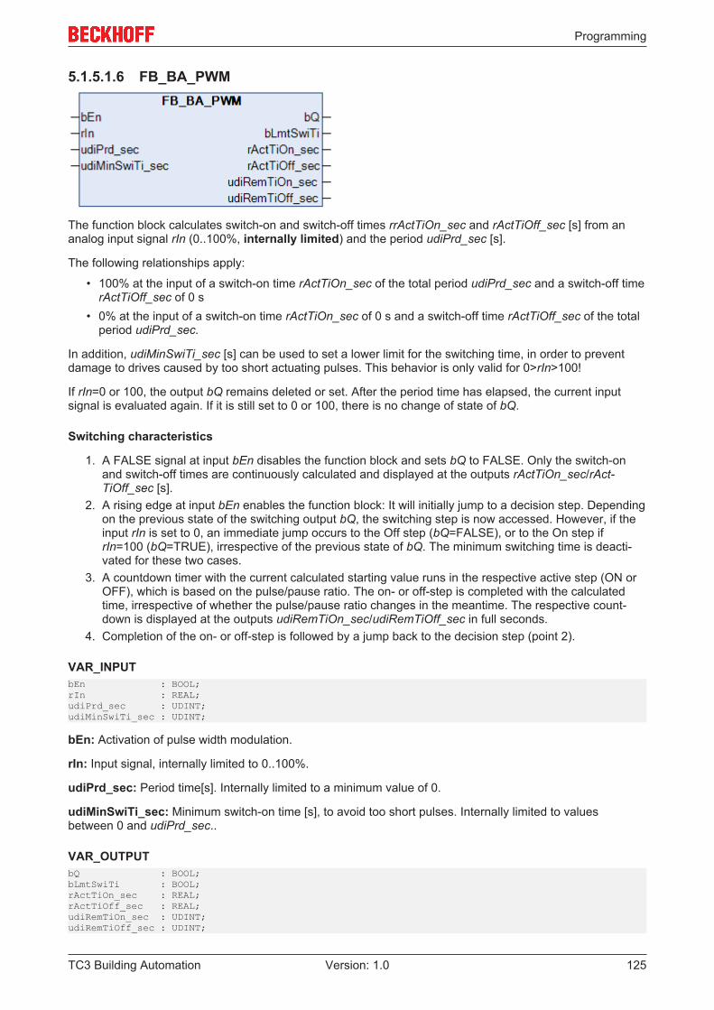
Programming
TC3 Building Automation 125Version: 1.0
5.1.5.1.6 FB_BA_PWM
The function block calculates switch-on and switch-off times rrActTiOn_sec and rActTiOff_sec [s] from ananalog input signal rIn (0..100%, internally limited) and the period udiPrd_sec [s].
The following relationships apply:
• 100% at the input of a switch-on time rActTiOn_sec of the total period udiPrd_sec and a switch-off timerActTiOff_sec of 0 s
• 0% at the input of a switch-on time rActTiOn_sec of 0 s and a switch-off time rActTiOff_sec of the totalperiod udiPrd_sec.
In addition, udiMinSwiTi_sec [s] can be used to set a lower limit for the switching time, in order to preventdamage to drives caused by too short actuating pulses. This behavior is only valid for 0>rIn>100!
If rIn=0 or 100, the output bQ remains deleted or set. After the period time has elapsed, the current inputsignal is evaluated again. If it is still set to 0 or 100, there is no change of state of bQ.
Switching characteristics
1. A FALSE signal at input bEn disables the function block and sets bQ to FALSE. Only the switch-onand switch-off times are continuously calculated and displayed at the outputs rActTiOn_sec/rAct-TiOff_sec [s].
2. A rising edge at input bEn enables the function block: It will initially jump to a decision step. Dependingon the previous state of the switching output bQ, the switching step is now accessed. However, if theinput rIn is set to 0, an immediate jump occurs to the Off step (bQ=FALSE), or to the On step ifrIn=100 (bQ=TRUE), irrespective of the previous state of bQ. The minimum switching time is deacti-vated for these two cases.
3. A countdown timer with the current calculated starting value runs in the respective active step (ON orOFF), which is based on the pulse/pause ratio. The on- or off-step is completed with the calculatedtime, irrespective of whether the pulse/pause ratio changes in the meantime. The respective count-down is displayed at the outputs udiRemTiOn_sec/udiRemTiOff_sec in full seconds.
4. Completion of the on- or off-step is followed by a jump back to the decision step (point 2).
VAR_INPUTbEn : BOOL;rIn : REAL;udiPrd_sec : UDINT;udiMinSwiTi_sec : UDINT;
bEn: Activation of pulse width modulation.
rIn: Input signal, internally limited to 0..100%.
udiPrd_sec: Period time[s]. Internally limited to a minimum value of 0.
udiMinSwiTi_sec: Minimum switch-on time [s], to avoid too short pulses. Internally limited to valuesbetween 0 and udiPrd_sec..
VAR_OUTPUTbQ : BOOL;bLmtSwiTi : BOOL;rActTiOn_sec : REAL;rActTiOff_sec : REAL;udiRemTiOn_sec : UDINT;udiRemTiOff_sec : UDINT;
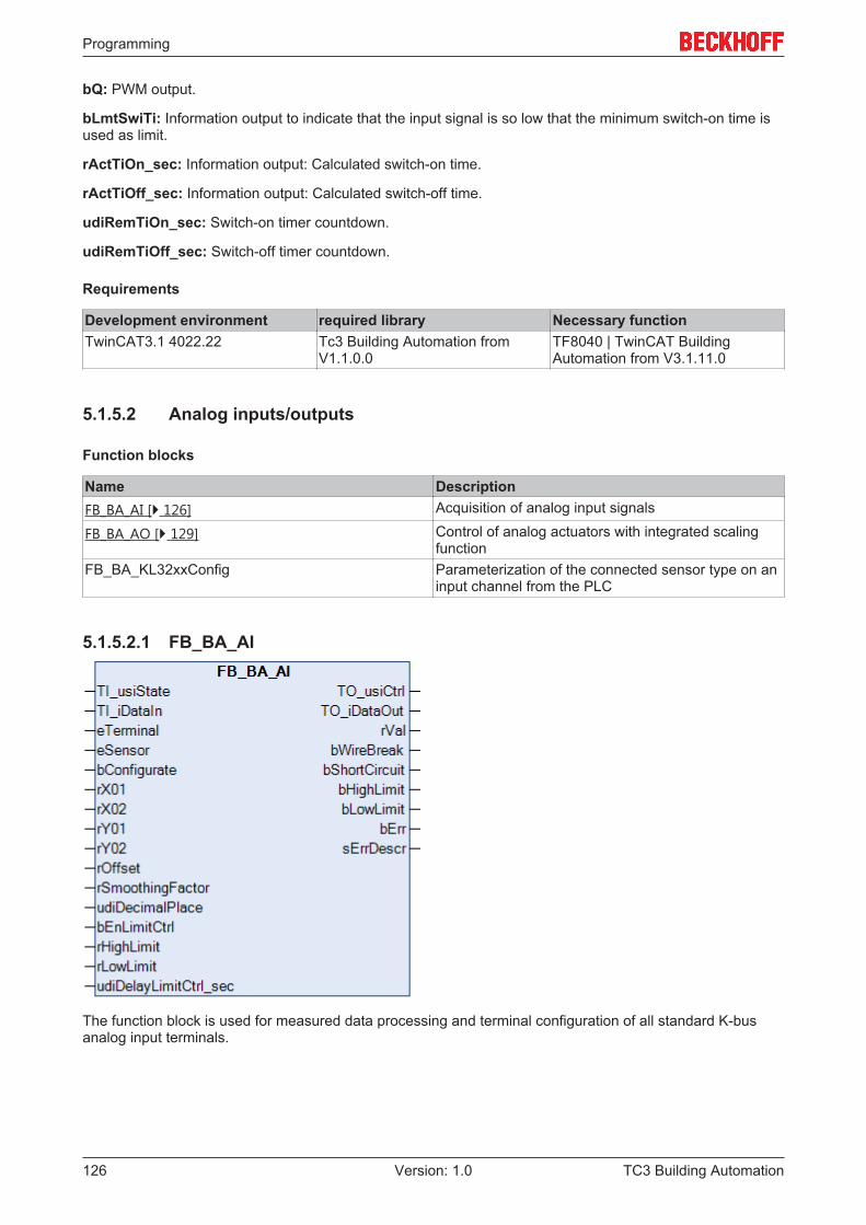
Programming
TC3 Building Automation126 Version: 1.0
bQ: PWM output.
bLmtSwiTi: Information output to indicate that the input signal is so low that the minimum switch-on time isused as limit.
rActTiOn_sec: Information output: Calculated switch-on time.
rActTiOff_sec: Information output: Calculated switch-off time.
udiRemTiOn_sec: Switch-on timer countdown.
udiRemTiOff_sec: Switch-off timer countdown.
Requirements
Development environment required library Necessary functionTwinCAT3.1 4022.22 Tc3 Building Automation from
V1.1.0.0TF8040 | TwinCAT BuildingAutomation from V3.1.11.0
5.1.5.2 Analog inputs/outputs
Function blocks
Name DescriptionFB_BA_AI [} 126] Acquisition of analog input signals
FB_BA_AO [} 129] Control of analog actuators with integrated scalingfunction
FB_BA_KL32xxConfig Parameterization of the connected sensor type on aninput channel from the PLC
5.1.5.2.1 FB_BA_AI
The function block is used for measured data processing and terminal configuration of all standard K-busanalog input terminals.
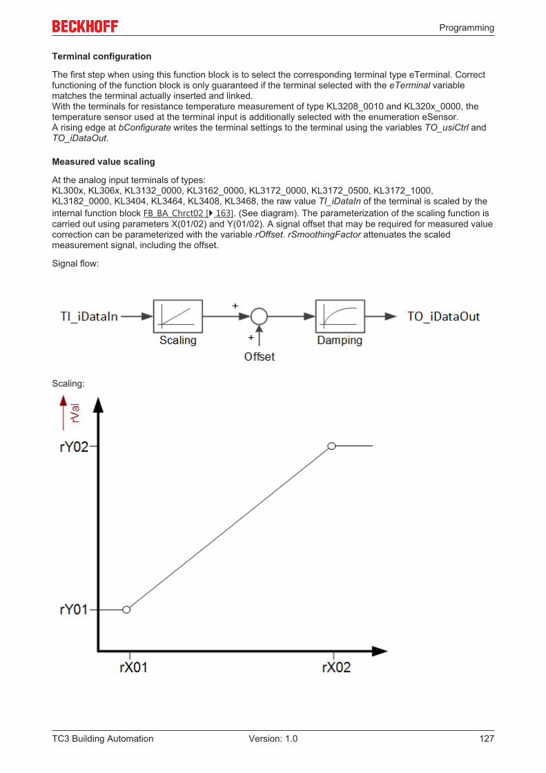
Programming
TC3 Building Automation 127Version: 1.0
Terminal configuration
The first step when using this function block is to select the corresponding terminal type eTerminal. Correctfunctioning of the function block is only guaranteed if the terminal selected with the eTerminal variablematches the terminal actually inserted and linked.With the terminals for resistance temperature measurement of type KL3208_0010 and KL320x_0000, thetemperature sensor used at the terminal input is additionally selected with the enumeration eSensor.A rising edge at bConfigurate writes the terminal settings to the terminal using the variables TO_usiCtrl andTO_iDataOut.
Measured value scaling
At the analog input terminals of types:KL300x, KL306x, KL3132_0000, KL3162_0000, KL3172_0000, KL3172_0500, KL3172_1000,KL3182_0000, KL3404, KL3464, KL3408, KL3468, the raw value TI_iDataIn of the terminal is scaled by theinternal function block FB_BA_Chrct02 [} 163]. (See diagram). The parameterization of the scaling function iscarried out using parameters X(01/02) and Y(01/02). A signal offset that may be required for measured valuecorrection can be parameterized with the variable rOffset. rSmoothingFactor attenuates the scaledmeasurement signal, including the offset.
Signal flow:
Scaling:
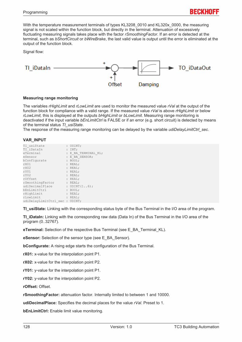
Programming
TC3 Building Automation128 Version: 1.0
With the temperature measurement terminals of types KL3208_0010 and KL320x_0000, the measuringsignal is not scaled within the function block, but directly in the terminal. Attenuation of excessivelyfluctuating measuring signals takes place with the factor rSmoothingFactor. If an error is detected at theterminal, such as bShortCircuit or bWireBrake, the last valid value is output until the error is eliminated at theoutput of the function block.
Signal flow:
Measuring range monitoring
The variables rHighLimit and rLowLimit are used to monitor the measured value rVal at the output of thefunction block for compliance with a valid range. If the measured value rVal is above rHighLimit or belowrLowLimit, this is displayed at the outputs bHighLimit or bLowLimit. Measuring range monitoring isdeactivated if the input variable bEnLimitCtrl is FALSE or if an error (e.g. short circuit) is detected by meansof the terminal status TI_usiState.The response of the measuring range monitoring can be delayed by the variable udiDelayLimitCtrl_sec.
VAR_INPUTTI_usiState : USINT;TI_iDataIn : INT;eTerminal : E_BA_TERMINAL_KL;eSensor : E_BA_SENSOR;bConfigurate : BOOL;rX01 : REAL;rX02 : REAL;rY01 : REAL;rY02 : REAL;rOffset : REAL;rSmoothingFactor : REAL;udiDecimalPlace : UDINT(1..6);bEnLimitCtrl : BOOL;rHighLimit : REAL;rLowLimit : REAL;udiDelayLimitCtrl_sec : UDINT;
TI_usiState: Linking with the corresponding status byte of the Bus Terminal in the I/O area of the program.
TI_iDataIn: Linking with the corresponding raw data (Data In) of the Bus Terminal in the I/O area of theprogram (0..32767).
eTerminal: Selection of the respective Bus Terminal (see E_BA_Terminal_KL).
eSensor: Selection of the sensor type (see E_BA_Sensor).
bConfigurate: A rising edge starts the configuration of the Bus Terminal.
rX01: x-value for the interpolation point P1.
rX02: x-value for the interpolation point P2.
rY01: y-value for the interpolation point P1.
rY02: y-value for the interpolation point P2.
rOffset: Offset.
rSmoothingFactor: attenuation factor. Internally limited to between 1 and 10000.
udiDecimalPlace: Specifies the decimal places for the value rVal. Preset to 1.
bEnLimitCtrl: Enable limit value monitoring.
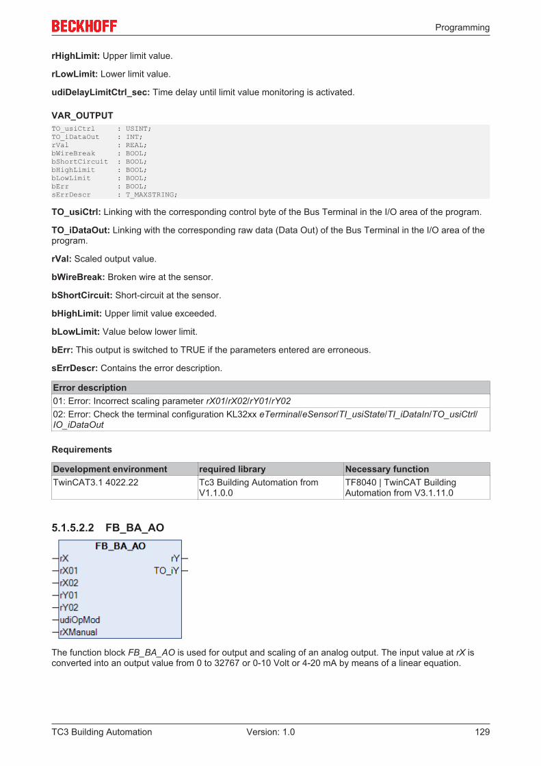
Programming
TC3 Building Automation 129Version: 1.0
rHighLimit: Upper limit value.
rLowLimit: Lower limit value.
udiDelayLimitCtrl_sec: Time delay until limit value monitoring is activated.
VAR_OUTPUTTO_usiCtrl : USINT;TO_iDataOut : INT;rVal : REAL;bWireBreak : BOOL;bShortCircuit : BOOL;bHighLimit : BOOL;bLowLimit : BOOL;bErr : BOOL;sErrDescr : T_MAXSTRING;
TO_usiCtrl: Linking with the corresponding control byte of the Bus Terminal in the I/O area of the program.
TO_iDataOut: Linking with the corresponding raw data (Data Out) of the Bus Terminal in the I/O area of theprogram.
rVal: Scaled output value.
bWireBreak: Broken wire at the sensor.
bShortCircuit: Short-circuit at the sensor.
bHighLimit: Upper limit value exceeded.
bLowLimit: Value below lower limit.
bErr: This output is switched to TRUE if the parameters entered are erroneous.
sErrDescr: Contains the error description.
Error description01: Error: Incorrect scaling parameter rX01/rX02/rY01/rY0202: Error: Check the terminal configuration KL32xx eTerminal/eSensor/TI_usiState/TI_iDataIn/TO_usiCtrl/IO_iDataOut
Requirements
Development environment required library Necessary functionTwinCAT3.1 4022.22 Tc3 Building Automation from
V1.1.0.0TF8040 | TwinCAT BuildingAutomation from V3.1.11.0
5.1.5.2.2 FB_BA_AO
The function block FB_BA_AO is used for output and scaling of an analog output. The input value at rX isconverted into an output value from 0 to 32767 or 0-10 Volt or 4-20 mA by means of a linear equation.
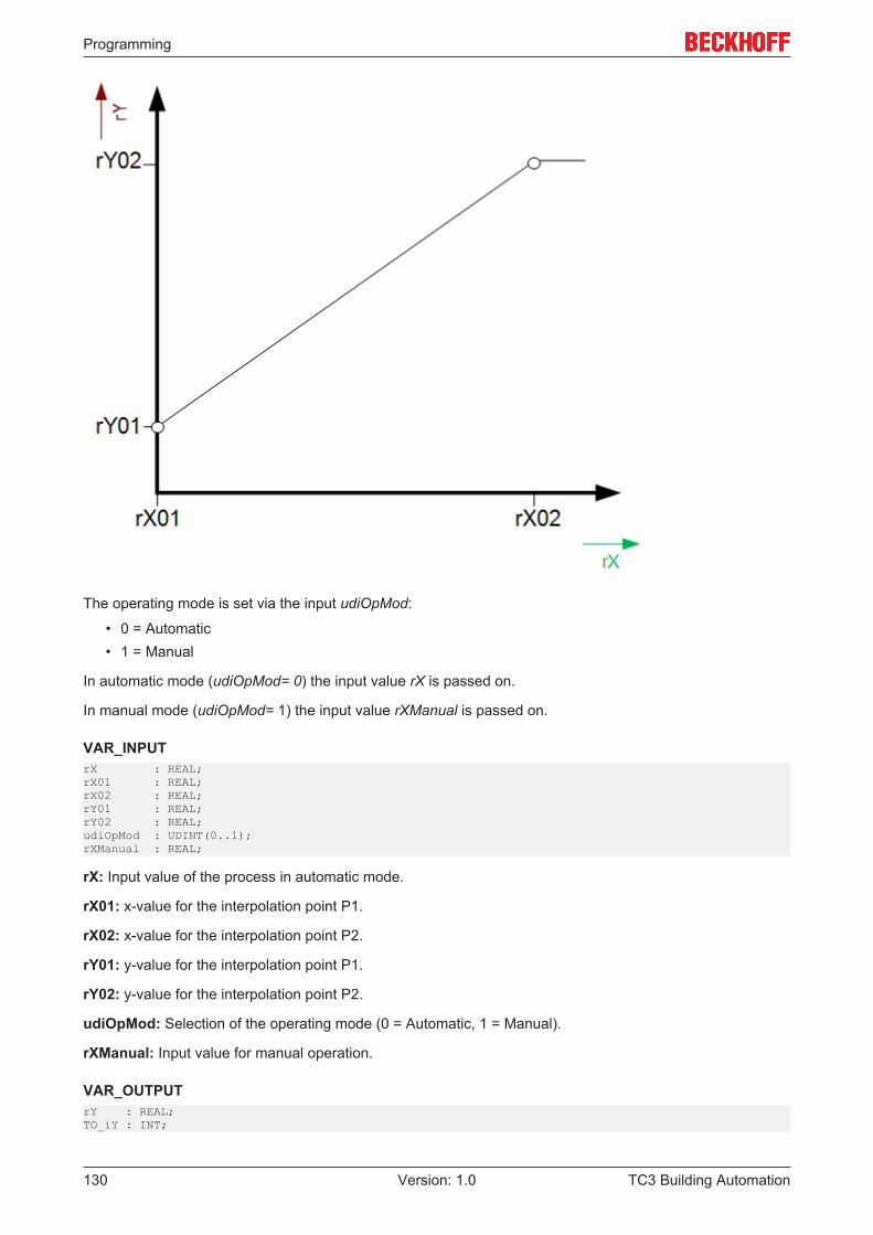
Programming
TC3 Building Automation130 Version: 1.0
The operating mode is set via the input udiOpMod:
• 0 = Automatic• 1 = Manual
In automatic mode (udiOpMod= 0) the input value rX is passed on.
In manual mode (udiOpMod= 1) the input value rXManual is passed on.
VAR_INPUTrX : REAL;rX01 : REAL;rX02 : REAL;rY01 : REAL;rY02 : REAL;udiOpMod : UDINT(0..1);rXManual : REAL;
rX: Input value of the process in automatic mode.
rX01: x-value for the interpolation point P1.
rX02: x-value for the interpolation point P2.
rY01: y-value for the interpolation point P1.
rY02: y-value for the interpolation point P2.
udiOpMod: Selection of the operating mode (0 = Automatic, 1 = Manual).
rXManual: Input value for manual operation.
VAR_OUTPUTrY : REAL;TO_iY : INT;
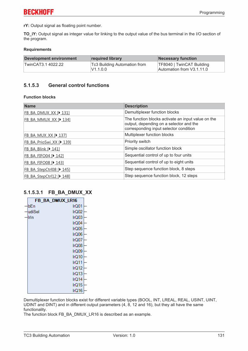
Programming
TC3 Building Automation 131Version: 1.0
rY: Output signal as floating point number.
TO_iY: Output signal as integer value for linking to the output value of the bus terminal in the I/O section ofthe program.
Requirements
Development environment required library Necessary functionTwinCAT3.1 4022.22 Tc3 Building Automation from
V1.1.0.0TF8040 | TwinCAT BuildingAutomation from V3.1.11.0
5.1.5.3 General control functions
Function blocks
Name DescriptionFB_BA_DMUX_XX [} 131] Demultiplexer function blocks
FB_BA_MMUX_XX [} 134] The function blocks activate an input value on theoutput, depending on a selector and thecorresponding input selector condition
FB_BA_MUX_XX [} 137] Multiplexer function blocks
FB_BA_PrioSwi_XX [} 139] Priority switch
FB_BA_Blink [} 141] Simple oscillator function block
FB_BA_FIFO04 [} 142] Sequential control of up to four units
FB_BA_FIFO08 [} 143] Sequential control of up to eight units
FB_BA_StepCtrl08 [} 145] Step sequence function block, 8 steps
FB_BA_StepCtrl12 [} 148] Step sequence function block, 12 steps
5.1.5.3.1 FB_BA_DMUX_XX
Demultiplexer function blocks exist for different variable types (BOOL, INT, LREAL, REAL, USINT, UINT,UDINT and DINT) and in different output parameters (4, 8, 12 and 16), but they all have the samefunctionality.The function block FB_BA_DMUX_LR16 is described as an example.
Programming
TC3 Building Automation132 Version: 1.0
In active state (bEn=TRUE), the function block outputs the value at input lrIn at the output (lrQ01..lrQ16)whose number is entered at input udiSel. All other outputs are set to 0 (for boolean demultiplexers toFALSE).
Example:
Inputs OutputsbEn = TRUE lrQ01 = 0.0udiSel = 5 lrQ02 = 0.0lrIn = 32.5 lrQ03 = 0.0
lrQ04 = 0.0lrQ05 = 32.5lrQ06 = 0.0lrQ07 = 0.0lrQ08 = 0.0lrQ09 = 0.0lrQ10 = 0.0lrQ11 = 0.0lrQ12 = 0.0lrQ13 = 0.0lrQ14 = 0.0lrQ15 = 0.0lrQ16 = 0.0
If the value entered at udiSel is greater than the number of outputs, the value of lrIn is output at the "highest"output:
Inputs OutputsbEn = TRUE lrQ01 = 0.0udiSel = 25 lrQ02 = 0.0rIn = 32.5 lrQ03 = 0.0
lrQ04 = 0.0lrQ05 = 0.0lrQ06 = 0.0lrQ07 = 0.0lrQ08 = 0.0lrQ09 = 0.0lrQ10 = 0.0lrQ11 = 0.0lrQ12 = 0.0lrQ13 = 0.0lrQ14 = 0.0lrQ15 = 0.0lrQ16 = 32.5
If bEn = FALSE, 0.0 is output at all outputs, or FALSE for boolean demultiplexers.
VAR_INPUTbEn : BOOL;udiSel : UDINT;rIn : LREAL;
bEn: Activation of the block function.
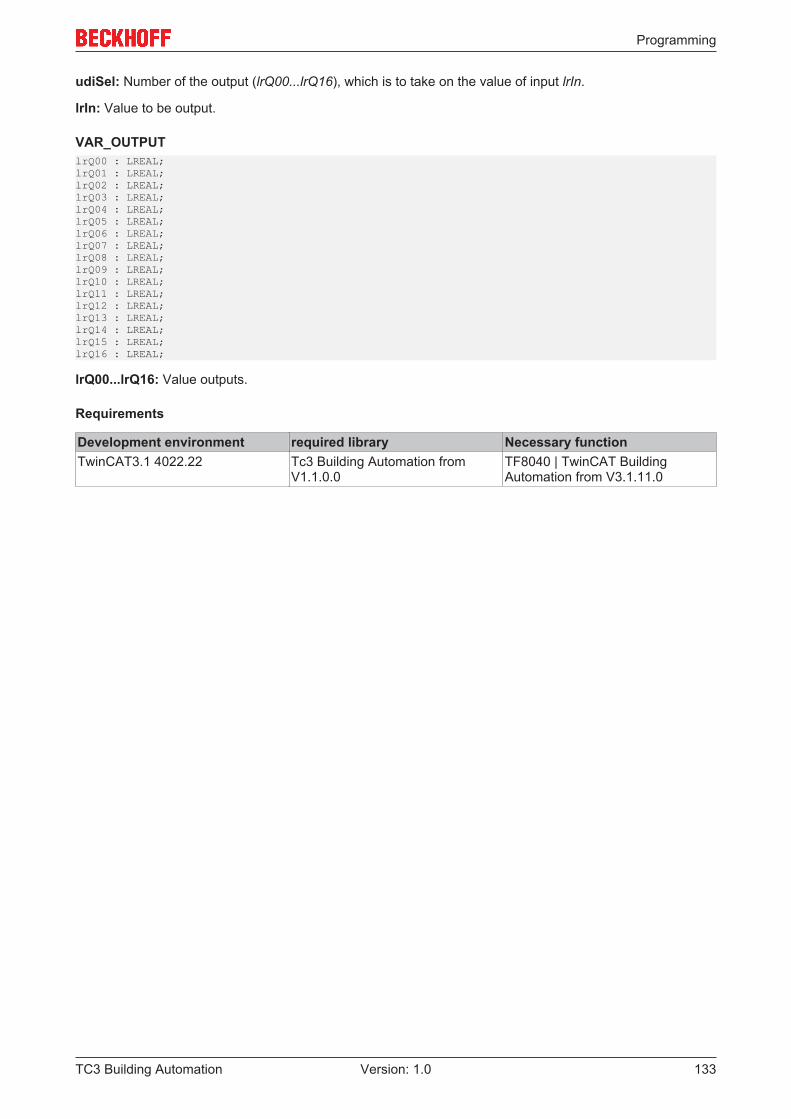
Programming
TC3 Building Automation 133Version: 1.0
udiSel: Number of the output (lrQ00...lrQ16), which is to take on the value of input lrIn.
lrIn: Value to be output.
VAR_OUTPUTlrQ00 : LREAL;lrQ01 : LREAL;lrQ02 : LREAL;lrQ03 : LREAL;lrQ04 : LREAL;lrQ05 : LREAL;lrQ06 : LREAL;lrQ07 : LREAL;lrQ08 : LREAL;lrQ09 : LREAL;lrQ10 : LREAL;lrQ11 : LREAL;lrQ12 : LREAL;lrQ13 : LREAL;lrQ14 : LREAL;lrQ15 : LREAL;lrQ16 : LREAL;
lrQ00...lrQ16: Value outputs.
Requirements
Development environment required library Necessary functionTwinCAT3.1 4022.22 Tc3 Building Automation from
V1.1.0.0TF8040 | TwinCAT BuildingAutomation from V3.1.11.0
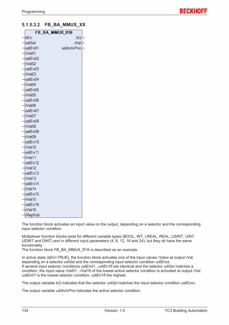
Programming
TC3 Building Automation134 Version: 1.0
5.1.5.3.2 FB_BA_MMUX_XX
The function block activates an input value on the output, depending on a selector and the correspondinginput selector condition.
Multiplexer function blocks exist for different variable types (BOOL, INT, LREAL, REAL, USINT, UINT,UDINT and DINT) and in different input parameters (4, 8, 12, 16 and 24), but they all have the samefunctionality.The function block FB_BA_MMUX_R16 is described as an example.
In active state (bEn=TRUE), the function block activates one of the input values rValxx at output rVal,depending on a selector udiSel and the corresponding input selector condition udiEnxx.If several input selector conditions udiEn01...udiEn16 are identical and the selector udiSel matches acondition, the input value rVal01...rVal16 of the lowest active selector condition is activated at output rVal.udiEn01 is the lowest selector condition, udiEn16 the highest.
The output variable bQ indicates that the selector udiSel matches the input selector condition udiEnxx.
The output variable udiActvPrio indicates the active selector condition.
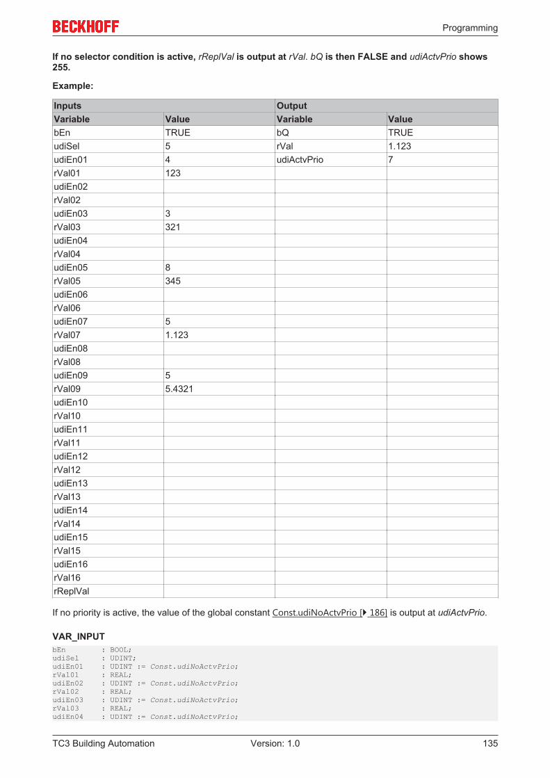
Programming
TC3 Building Automation 135Version: 1.0
If no selector condition is active, rReplVal is output at rVal. bQ is then FALSE and udiActvPrio shows255.
Example:
Inputs OutputVariable Value Variable ValuebEn TRUE bQ TRUEudiSel 5 rVal 1.123udiEn01 4 udiActvPrio 7rVal01 123udiEn02rVal02udiEn03 3rVal03 321udiEn04rVal04udiEn05 8rVal05 345udiEn06rVal06udiEn07 5rVal07 1.123udiEn08rVal08udiEn09 5rVal09 5.4321udiEn10rVal10udiEn11rVal11udiEn12rVal12udiEn13rVal13udiEn14rVal14udiEn15rVal15udiEn16rVal16rReplVal
If no priority is active, the value of the global constant Const.udiNoActvPrio [} 186] is output at udiActvPrio.
VAR_INPUTbEn : BOOL;udiSel : UDINT;udiEn01 : UDINT := Const.udiNoActvPrio;rVal01 : REAL;udiEn02 : UDINT := Const.udiNoActvPrio;rVal02 : REAL;udiEn03 : UDINT := Const.udiNoActvPrio;rVal03 : REAL;udiEn04 : UDINT := Const.udiNoActvPrio;
Programming
TC3 Building Automation136 Version: 1.0
rVal04 : REAL;udiEn05 : UDINT := Const.udiNoActvPrio;rVal05 : REAL;udiEn06 : UDINT := Const.udiNoActvPrio;rVal06 : REAL;udiEn07 : UDINT := Const.udiNoActvPrio;rVal07 : REAL;udiEn08 : UDINT := Const.udiNoActvPrio;rVal08 : REAL;udiEn09 : UDINT := Const.udiNoActvPrio;rVal09 : REAL;udiEn10 : UDINT := Const.udiNoActvPrio;rVal10 : REAL;udiEn11 : UDINT := Const.udiNoActvPrio;rVal11 : REAL;udiEn12 : UDINT := Const.udiNoActvPrio;rVal12 : REAL;udiEn13 : UDINT := Const.udiNoActvPrio;rVal13 : REAL;udiEn14 : UDINT := Const.udiNoActvPrio;rVal14 : REAL;udiEn15 : UDINT := Const.udiNoActvPrio;rVal15 : REAL;udiEn16 : UDINT := Const.udiNoActvPrio;rVal16 : REAL;rReplVal : REAL;
bEn: Activation of the block function.
udiSel: Selector. Internally limited to values between 0 and 4294967294.
udiEn01..udiEn16: Input selector condition.The input variables are pre-initialized to the value 255.
rVal01...rVal16: Input values to select from.
rReplVal: Substitute value, if no input selector condition is active
VAR_OUTPUTbQ : BOOL;rVal : REAL;udiActvPrio : UDINT;
bQ: TRUE, if the selector udiSel matches an input selector condition udiEnxx.
rVal: Value of the selected input selector condition.
udiActvPrio: Indicates which input selector condition is active. If no priority is active, the value of the globalconstant Const.udiNoActvPrio [} 186] is output at udiActvPrio.
Requirements
Development environment required library Necessary functionTwinCAT3.1 4022.22 Tc3 Building Automation from
V1.1.0.0TF8040 | TwinCAT BuildingAutomation from V3.1.11.0
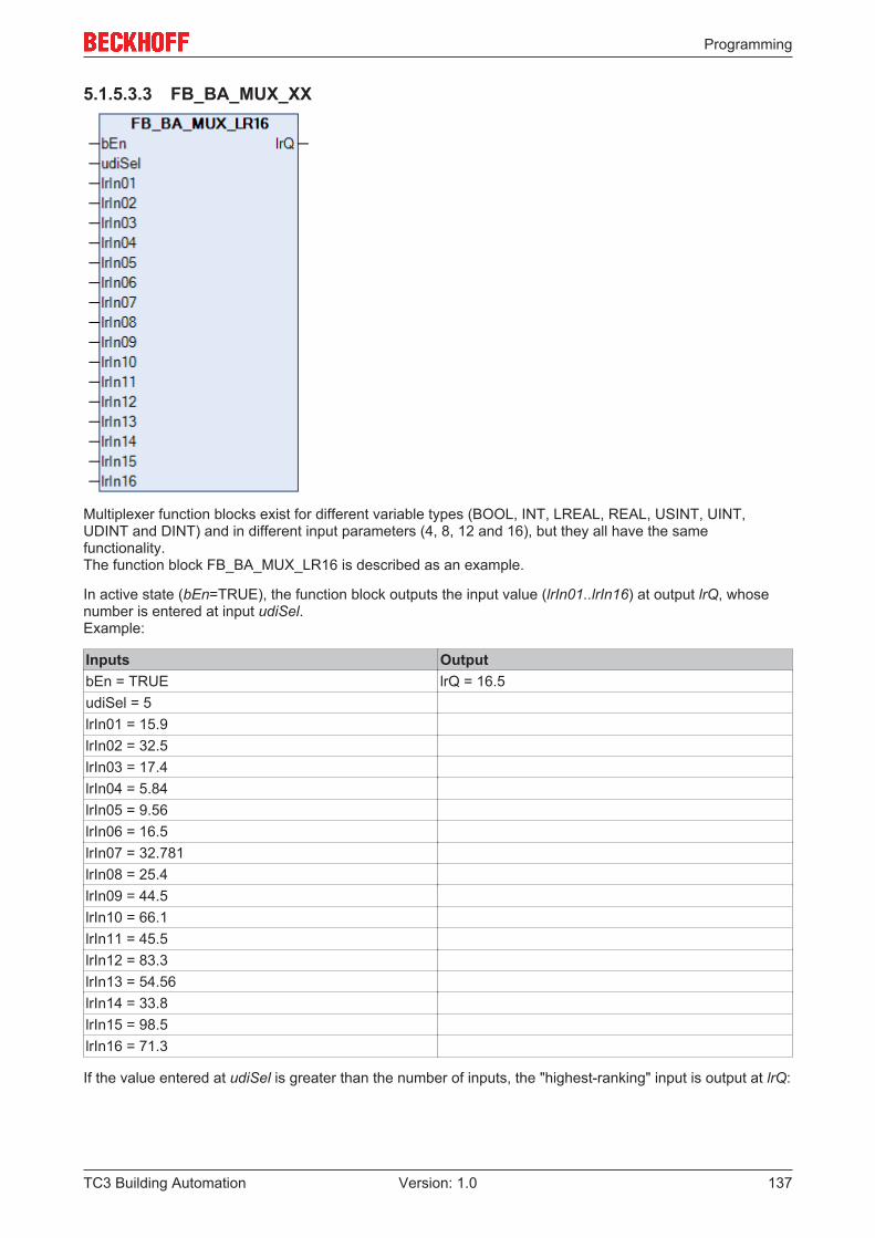
Programming
TC3 Building Automation 137Version: 1.0
5.1.5.3.3 FB_BA_MUX_XX
Multiplexer function blocks exist for different variable types (BOOL, INT, LREAL, REAL, USINT, UINT,UDINT and DINT) and in different input parameters (4, 8, 12 and 16), but they all have the samefunctionality.The function block FB_BA_MUX_LR16 is described as an example.
In active state (bEn=TRUE), the function block outputs the input value (lrIn01..lrIn16) at output lrQ, whosenumber is entered at input udiSel.Example:
Inputs OutputbEn = TRUE lrQ = 16.5udiSel = 5lrIn01 = 15.9lrIn02 = 32.5lrIn03 = 17.4lrIn04 = 5.84lrIn05 = 9.56lrIn06 = 16.5lrIn07 = 32.781lrIn08 = 25.4lrIn09 = 44.5lrIn10 = 66.1lrIn11 = 45.5lrIn12 = 83.3lrIn13 = 54.56lrIn14 = 33.8lrIn15 = 98.5lrIn16 = 71.3
If the value entered at udiSel is greater than the number of inputs, the "highest-ranking" input is output at lrQ:
Programming
TC3 Building Automation138 Version: 1.0
Inputs Output bEn = TRUE lrQ = 2.3udiSel = 25lrIn01 = 15.9lrIn02 = 32.5lrIn03 = 17.4lrIn04 = 5.84lrIn05 = 9.56lrIn06 = 16.5lrIn07 = 32.781lrIn08 = 25.4lrIn09 = 44.5lrIn10 = 66.1lrIn11 = 45.5lrIn12 = 83.3lrIn13 = 54.56lrIn14 = 33.8lrIn15 = 98.5lrIn16 = 71.3
If bEn=FALSE, 0.0 is output at lrQ, or FALSE for boolean multiplexers.
VAR_INPUTbEn : BOOL;udiSel : UDINT;lrIn00 : LREAL;lrIn01 : LREAL;lrIn02 : LREAL;lrIn03 : LREAL;lrIn04 : LREAL;lrIn05 : LREAL;lrIn06 : LREAL;lrIn07 : LREAL;lrIn08 : LREAL;lrIn09 : LREAL;lrIn10 : LREAL;lrIn11 : LREAL;lrIn12 : LREAL;lrIn13 : LREAL;lrIn14 : LREAL;lrIn15 : LREAL;lrIn16 : LREAL;
bEn: Activation of the block function.
udiSel: Number of the input, whose value is to be output at lrQ.
lr00...lr16: Input values to select from.
VAR_OUTPUTlrQ : LREAL;
lrQ: Value of the selected input.
Requirements
Development environment required library Necessary functionTwinCAT3.1 4022.22 Tc3 Building Automation from
V1.1.0.0TF8040 | TwinCAT BuildingAutomation from V3.1.11.0
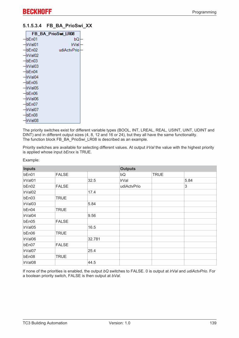
Programming
TC3 Building Automation 139Version: 1.0
5.1.5.3.4 FB_BA_PrioSwi_XX
The priority switches exist for different variable types (BOOL, INT, LREAL, REAL, USINT, UINT, UDINT andDINT) and in different output sizes (4, 8, 12 and 16 or 24), but they all have the same functionality.The function block FB_BA_PrioSwi_LR08 is described as an example.
Priority switches are available for selecting different values. At output lrVal the value with the highest priorityis applied whose input bEnxx is TRUE.
Example:
Inputs OutputsbEn01 FALSE bQ TRUElrVal01 32.5 lrVal 5.84bEn02 FALSE udiActvPrio 3lrVal02 17.4bEn03 TRUElrVal03 5.84bEn04 TRUElrVal04 9.56bEn05 FALSElrVal05 16.5bEn06 TRUElrVal06 32.781bEn07 FALSElrVal07 25.4bEn08 TRUElrVal08 44.5
If none of the priorities is enabled, the output bQ switches to FALSE. 0 is output at lrVal and udiActvPrio. Fora boolean priority switch, FALSE is then output at bVal.
Programming
TC3 Building Automation140 Version: 1.0
Inputs OutputsbEn01 FALSE bQ FALSElrVal01 32.5 lrVal 0.0bEn02 FALSE udiActvPrio 0lrVal02 17.4bEn03 FALSElrVal03 5.84bEn04 FALSElrVal04 9.56bEn05 FALSElrVal05 16.5bEn06 FALSElrVal06 32.781bEn07 FALSElrVal07 25.4bEn08 FALSElrVal08 44.5
If no priority is active, the value of the global constant ConstudiNoActvPrio is output at udiActvPrio.
VAR_INPUTbEn01 : BOOL;lrVal01 : LREAL;bEn02 : BOOL;lrVal02 : LREAL;bEn03 : BOOL;lrVal03 : LREAL;bEn04 : BOOL;lrVal04 : LREAL;bEn05 : BOOL;lrVal05 : LREAL;bEn06 : BOOL;lrVal06 : LREAL;bEn07 : BOOL;lrVal07 : LREAL;bEn08 : BOOL;lrVal08 : LREAL;
bEn01...bEn08: Enabling the priority value.
lrVal01...lrVal08: Priority value.
VAR_OUTPUTbQ : BOOL;lrVal : LREAL;udiActvPrio : UDINT;
bQ: Output to indicate whether a priority is enabled.
lrVal: Output of the value of the current (highest) priority that is enabled.
udiActvPrio: Current (highest) priority that is enabled.
Requirements
Development environment required library Necessary functionTwinCAT3.1 4022.22 Tc3 Building Automation from
V1.1.0.0TF8040 | TwinCAT BuildingAutomation from V3.1.11.0
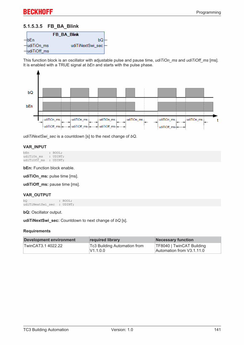
Programming
TC3 Building Automation 141Version: 1.0
5.1.5.3.5 FB_BA_Blink
This function block is an oscillator with adjustable pulse and pause time, udiTiOn_ms and udiTiOff_ms [ms].It is enabled with a TRUE signal at bEn and starts with the pulse phase.
udiTiNextSwi_sec is a countdown [s] to the next change of bQ.
VAR_INPUTbEn : BOOL;udiTiOn_ms : UDINT;udiTiOff_ms : UDINT;
bEn: Function block enable.
udiTiOn_ms: pulse time [ms].
udiTiOff_ms: pause time [ms].
VAR_OUTPUTbQ : BOOL;udiTiNextSwi_sec : UDINT;
bQ: Oscillator output.
udiTiNextSwi_sec: Countdown to next change of bQ [s].
Requirements
Development environment required library Necessary functionTwinCAT3.1 4022.22 Tc3 Building Automation from
V1.1.0.0TF8040 | TwinCAT BuildingAutomation from V3.1.11.0
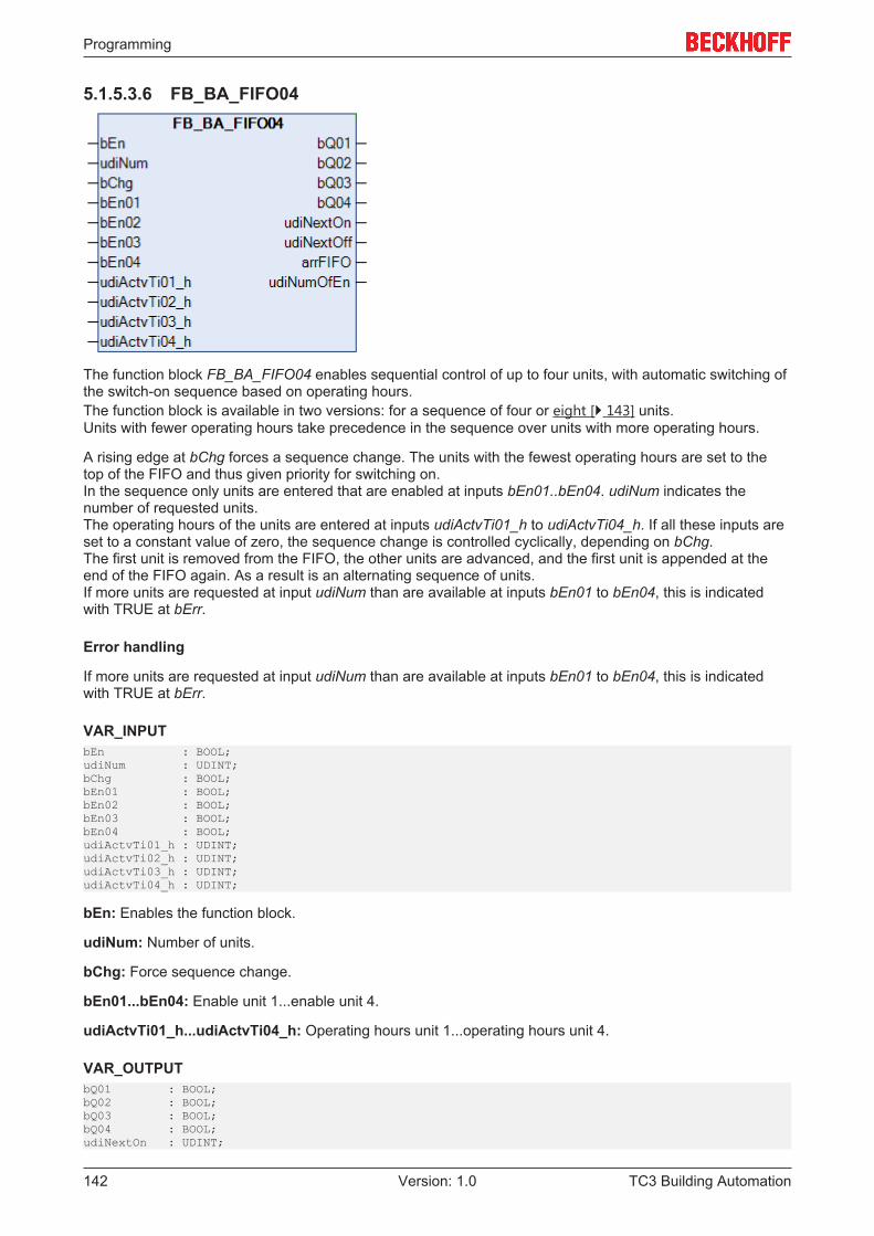
Programming
TC3 Building Automation142 Version: 1.0
5.1.5.3.6 FB_BA_FIFO04
The function block FB_BA_FIFO04 enables sequential control of up to four units, with automatic switching ofthe switch-on sequence based on operating hours.The function block is available in two versions: for a sequence of four or eight [} 143] units.Units with fewer operating hours take precedence in the sequence over units with more operating hours.
A rising edge at bChg forces a sequence change. The units with the fewest operating hours are set to thetop of the FIFO and thus given priority for switching on.In the sequence only units are entered that are enabled at inputs bEn01..bEn04. udiNum indicates thenumber of requested units.The operating hours of the units are entered at inputs udiActvTi01_h to udiActvTi04_h. If all these inputs areset to a constant value of zero, the sequence change is controlled cyclically, depending on bChg.The first unit is removed from the FIFO, the other units are advanced, and the first unit is appended at theend of the FIFO again. As a result is an alternating sequence of units.If more units are requested at input udiNum than are available at inputs bEn01 to bEn04, this is indicatedwith TRUE at bErr.
Error handling
If more units are requested at input udiNum than are available at inputs bEn01 to bEn04, this is indicatedwith TRUE at bErr.
VAR_INPUTbEn : BOOL;udiNum : UDINT;bChg : BOOL;bEn01 : BOOL;bEn02 : BOOL;bEn03 : BOOL;bEn04 : BOOL;udiActvTi01_h : UDINT;udiActvTi02_h : UDINT;udiActvTi03_h : UDINT;udiActvTi04_h : UDINT;
bEn: Enables the function block.
udiNum: Number of units.
bChg: Force sequence change.
bEn01...bEn04: Enable unit 1...enable unit 4.
udiActvTi01_h...udiActvTi04_h: Operating hours unit 1...operating hours unit 4.
VAR_OUTPUTbQ01 : BOOL;bQ02 : BOOL;bQ03 : BOOL;bQ04 : BOOL;udiNextOn : UDINT;
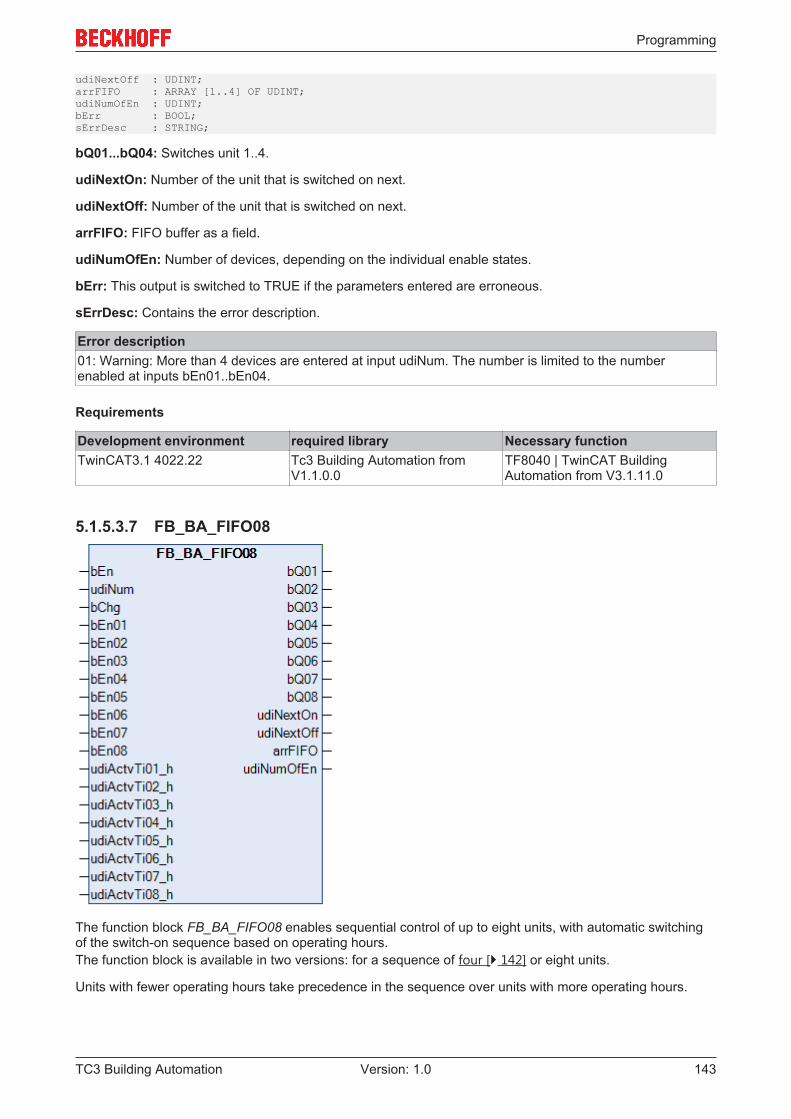
Programming
TC3 Building Automation 143Version: 1.0
udiNextOff : UDINT;arrFIFO : ARRAY [1..4] OF UDINT;udiNumOfEn : UDINT;bErr : BOOL;sErrDesc : STRING;
bQ01...bQ04: Switches unit 1..4.
udiNextOn: Number of the unit that is switched on next.
udiNextOff: Number of the unit that is switched on next.
arrFIFO: FIFO buffer as a field.
udiNumOfEn: Number of devices, depending on the individual enable states.
bErr: This output is switched to TRUE if the parameters entered are erroneous.
sErrDesc: Contains the error description.
Error description01: Warning: More than 4 devices are entered at input udiNum. The number is limited to the numberenabled at inputs bEn01..bEn04.
Requirements
Development environment required library Necessary functionTwinCAT3.1 4022.22 Tc3 Building Automation from
V1.1.0.0TF8040 | TwinCAT BuildingAutomation from V3.1.11.0
5.1.5.3.7 FB_BA_FIFO08
The function block FB_BA_FIFO08 enables sequential control of up to eight units, with automatic switchingof the switch-on sequence based on operating hours.The function block is available in two versions: for a sequence of four [} 142] or eight units.
Units with fewer operating hours take precedence in the sequence over units with more operating hours.
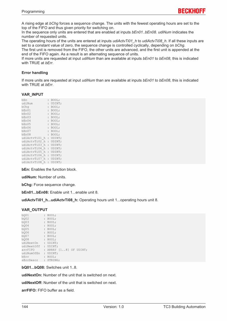
Programming
TC3 Building Automation144 Version: 1.0
A rising edge at bChg forces a sequence change. The units with the fewest operating hours are set to thetop of the FIFO and thus given priority for switching on.In the sequence only units are entered that are enabled at inputs bEn01..bEn08. udiNum indicates thenumber of requested units.The operating hours of the units are entered at inputs udiActvTi01_h to udiActvTi08_h. If all these inputs areset to a constant value of zero, the sequence change is controlled cyclically, depending on bChg.The first unit is removed from the FIFO, the other units are advanced, and the first unit is appended at theend of the FIFO again. As a result is an alternating sequence of units.If more units are requested at input udiNum than are available at inputs bEn01 to bEn08, this is indicatedwith TRUE at bErr.
Error handling
If more units are requested at input udiNum than are available at inputs bEn01 to bEn08, this is indicatedwith TRUE at bErr.
VAR_INPUTbEn : BOOL;udiNum : UDINT;bChg : BOOL;bEn01 : BOOL;bEn02 : BOOL;bEn03 : BOOL;bEn04 : BOOL;bEn05 : BOOL;bEn06 : BOOL;bEn07 : BOOL;bEn08 : BOOL;udiActvTi01_h : UDINT;udiActvTi02_h : UDINT;udiActvTi03_h : UDINT;udiActvTi04_h : UDINT;udiActvTi05_h : UDINT;udiActvTi06_h : UDINT;udiActvTi07_h : UDINT;udiActvTi08_h : UDINT;
bEn: Enables the function block.
udiNum: Number of units.
bChg: Force sequence change.
bEn01...bEn08: Enable unit 1...enable unit 8.
udiActvTi01_h...udiActvTi08_h: Operating hours unit 1...operating hours unit 8.
VAR_OUTPUTbQ01 : BOOL;bQ02 : BOOL;bQ03 : BOOL;bQ04 : BOOL;bQ05 : BOOL;bQ06 : BOOL;bQ07 : BOOL;bQ08 : BOOL;udiNextOn : UDINT;udiNextOff : UDINT;arrFIFO : ARRAY [1..8] OF UDINT;udiNumOfEn : UDINT;bErr : BOOL;sErrDescr : STRING;
bQ01...bQ08: Switches unit 1..8.
udiNextOn: Number of the unit that is switched on next.
udiNextOff: Number of the unit that is switched on next.
arrFIFO: FIFO buffer as a field.
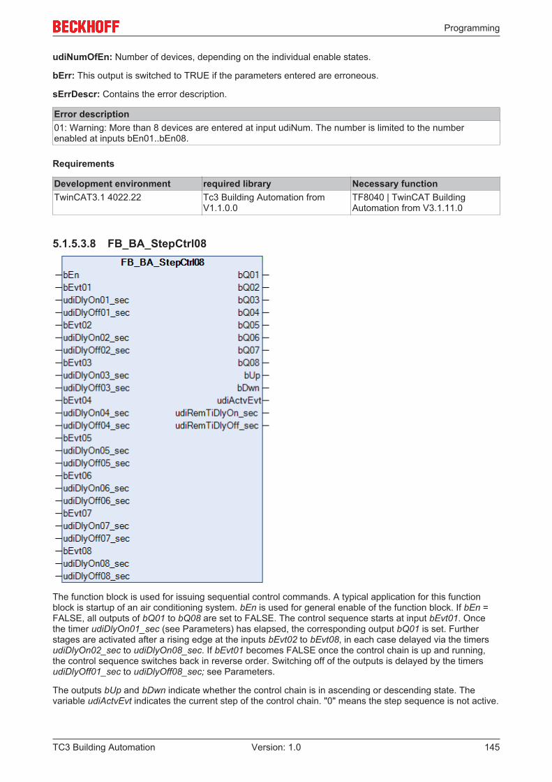
Programming
TC3 Building Automation 145Version: 1.0
udiNumOfEn: Number of devices, depending on the individual enable states.
bErr: This output is switched to TRUE if the parameters entered are erroneous.
sErrDescr: Contains the error description.
Error description01: Warning: More than 8 devices are entered at input udiNum. The number is limited to the numberenabled at inputs bEn01..bEn08.
Requirements
Development environment required library Necessary functionTwinCAT3.1 4022.22 Tc3 Building Automation from
V1.1.0.0TF8040 | TwinCAT BuildingAutomation from V3.1.11.0
5.1.5.3.8 FB_BA_StepCtrl08
The function block is used for issuing sequential control commands. A typical application for this functionblock is startup of an air conditioning system. bEn is used for general enable of the function block. If bEn =FALSE, all outputs of bQ01 to bQ08 are set to FALSE. The control sequence starts at input bEvt01. Oncethe timer udiDlyOn01_sec (see Parameters) has elapsed, the corresponding output bQ01 is set. Furtherstages are activated after a rising edge at the inputs bEvt02 to bEvt08, in each case delayed via the timersudiDlyOn02_sec to udiDlyOn08_sec. If bEvt01 becomes FALSE once the control chain is up and running,the control sequence switches back in reverse order. Switching off of the outputs is delayed by the timersudiDlyOff01_sec to udiDlyOff08_sec; see Parameters.
The outputs bUp and bDwn indicate whether the control chain is in ascending or descending state. Thevariable udiActvEvt indicates the current step of the control chain. "0" means the step sequence is not active.
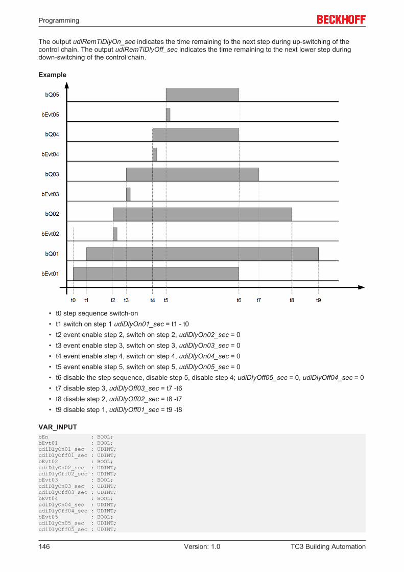
Programming
TC3 Building Automation146 Version: 1.0
The output udiRemTiDlyOn_sec indicates the time remaining to the next step during up-switching of thecontrol chain. The output udiRemTiDlyOff_sec indicates the time remaining to the next lower step duringdown-switching of the control chain.
Example
• t0 step sequence switch-on• t1 switch on step 1 udiDlyOn01_sec = t1 - t0• t2 event enable step 2, switch on step 2, udiDlyOn02_sec = 0• t3 event enable step 3, switch on step 3, udiDlyOn03_sec = 0• t4 event enable step 4, switch on step 4, udiDlyOn04_sec = 0• t5 event enable step 5, switch on step 5, udiDlyOn05_sec = 0• t6 disable the step sequence, disable step 5, disable step 4; udiDlyOff05_sec = 0, udiDlyOff04_sec = 0• t7 disable step 3, udiDlyOff03_sec = t7 -t6• t8 disable step 2, udiDlyOff02_sec = t8 -t7• t9 disable step 1, udiDlyOff01_sec = t9 -t8
VAR_INPUTbEn : BOOL;bEvt01 : BOOL;udiDlyOn01_sec : UDINT;udiDlyOff01_sec : UDINT;bEvt02 : BOOL;udiDlyOn02_sec : UDINT;udiDlyOff02_sec : UDINT;bEvt03 : BOOL;udiDlyOn03_sec : UDINT;udiDlyOff03_sec : UDINT;bEvt04 : BOOL;udiDlyOn04_sec : UDINT;udiDlyOff04_sec : UDINT;bEvt05 : BOOL;udiDlyOn05_sec : UDINT;udiDlyOff05_sec : UDINT;
Programming
TC3 Building Automation 147Version: 1.0
bEvt06 : BOOL;udiDlyOn06_sec : UDINT;udiDlyOff06_sec : UDINT;bEvt07 : BOOL;udiDlyOn07_sec : UDINT;udiDlyOff07_sec : UDINT;bEvt08 : BOOL;udiDlyOn08_sec : UDINT;udiDlyOff08_sec : UDINT;
bEn: Enable function block.
bEvt01..08: Switch-on command for steps 1 to 8.
udiDlyOn01..08_sec: Switch-on delay for output bQ01 .. 08 [s].
udiDlyOff01..08_sec: Switch-off delay for output bQ01 .. 08 [s].
VAR_OUTPUTbQ01 : BOOL;bQ02 : BOOL;bQ03 : BOOL;bQ04 : BOOL;bQ05 : BOOL;bQ06 : BOOL;bQ07 : BOOL;bQ08 : BOOL;bUp : BOOL;bDwn : BOOL;udiActvEvt : UDINT;udiRemTiDlyOn_sec : UDINT;udiRemTiDlyOff_sec : UDINT;
bQ01..08: Step 1 to 8 On.
bUp: Control chain is in ascending state.
bDwn: Control chain is in descending state.
udiActvEvt: Active step, display 0..8; "0" represents an active step sequence.
udiRTiDlyOn: Time remaining to up-switching to the next step [s].
udiRTiDlyOff: Time remaining to down-switching to the previous step [s].
Requirements
Development environment required library Necessary functionTwinCAT3.1 4022.22 Tc3 Building Automation from
V1.1.0.0TF8040 | TwinCAT BuildingAutomation from V3.1.11.0
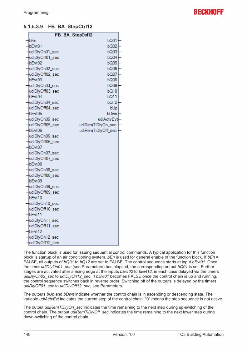
Programming
TC3 Building Automation148 Version: 1.0
5.1.5.3.9 FB_BA_StepCtrl12
The function block is used for issuing sequential control commands. A typical application for this functionblock is startup of an air conditioning system. bEn is used for general enable of the function block. If bEn =FALSE, all outputs of bQ01 to bQ12 are set to FALSE. The control sequence starts at input bEvt01. Oncethe timer udiDlyOn01_sec (see Parameters) has elapsed, the corresponding output bQ01 is set. Furtherstages are activated after a rising edge at the inputs bEvt02 to bEvt12, in each case delayed via the timersudiDlyOn02_sec to udiDlyOn12_sec. If bEvt01 becomes FALSE once the control chain is up and running,the control sequence switches back in reverse order. Switching off of the outputs is delayed by the timersudiDlyOff01_sec to udiDlyOff12_sec; see Parameters.
The outputs bUp and bDwn indicate whether the control chain is in ascending or descending state. Thevariable udiActvEvt indicates the current step of the control chain. "0" means the step sequence is not active.
The output udiRemTiDlyOn_sec indicates the time remaining to the next step during up-switching of thecontrol chain. The output udiRemTiDlyOff_sec indicates the time remaining to the next lower step duringdown-switching of the control chain.
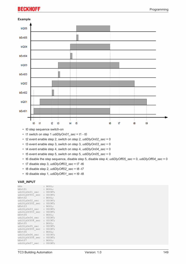
Programming
TC3 Building Automation 149Version: 1.0
Example
• t0 step sequence switch-on• t1 switch on step 1 udiDlyOn01_sec = t1 - t0• t2 event enable step 2, switch on step 2, udiDlyOn02_sec = 0• t3 event enable step 3, switch on step 3, udiDlyOn03_sec = 0• t4 event enable step 4, switch on step 4, udiDlyOn04_sec = 0• t5 event enable step 5, switch on step 5, udiDlyOn05_sec = 0• t6 disable the step sequence, disable step 5, disable step 4; udiDlyOff05_sec = 0, udiDlyOff04_sec = 0• t7 disable step 3, udiDlyOff03_sec = t7 -t6• t8 disable step 2, udiDlyOff02_sec = t8 -t7• t9 disable step 1, udiDlyOff01_sec = t9 -t8
VAR_INPUTbEn : BOOL;bEvt01 : BOOL;udiDlyOn01_sec : UDINT;udiDlyOff01_sec : UDINT;bEvt02 : BOOL;udiDlyOn02_sec : UDINT;udiDlyOff02_sec : UDINT;bEvt03 : BOOL;udiDlyOn03_sec : UDINT;udiDlyOff03_sec : UDINT;bEvt04 : BOOL;udiDlyOn04_sec : UDINT;udiDlyOff04_sec : UDINT;bEvt05 : BOOL;udiDlyOn05_sec : UDINT;udiDlyOff05_sec : UDINT;bEvt06 : BOOL;udiDlyOn06_sec : UDINT;udiDlyOff06_sec : UDINT;bEvt07 : BOOL;udiDlyOn07_sec : UDINT;
Programming
TC3 Building Automation150 Version: 1.0
udiDlyOff07_sec : UDINT;bEvt08 : BOOL;udiDlyOn08_sec : UDINT;udiDlyOff08_sec : UDINT;bEvt09 : BOOL;udiDlyOn09_sec : UDINT;udiDlyOff09_sec : UDINT;bEvt10 : BOOL;udiDlyOn10_sec : UDINT;udiDlyOff10_sec : UDINT;bEvt11 : BOOL;udiDlyOn11_sec : UDINT;udiDlyOff11_sec : UDINT;bEvt12 : BOOL;udiDlyOn12_sec : UDINT;udiDlyOff12_sec : UDINT;
bEn: Enable function block.
bEvt01..12: Switch-on command for steps 1 to 12.
udiDlyOn01..12_sec: Switch-on delay for output bQ01 .. 12 [s].
udiDlyOff01..12_sec: Switch-off delay for output bQ01 .. 12 [s].
VAR_OUTPUTbQ01 : BOOL;bQ02 : BOOL;bQ03 : BOOL;bQ04 : BOOL;bQ05 : BOOL;bQ06 : BOOL;bQ07 : BOOL;bQ08 : BOOL;bQ09 : BOOL;bQ10 : BOOL;bQ11 : BOOL;bQ12 : BOOL;bUp : BOOL;bDwn : BOOL;udiActvEvt : UDINT;udiRemTiDlyOn_sec : UDINT;udiRemTiDlyOff_sec : UDINT;
bQ01..12: Step 1 to 12 On.
bUp: Control chain is in ascending state.
bDwn: Control chain is in descending state.
udiActvEvt: Active step, display 0..12; "0" represents an active step sequence.
udiRTiDlyOn: Time remaining to up-switching to the next step [s].
udiRTiDlyOff: Time remaining to down-switching to the previous step [s].
Requirements
Development environment required library Necessary functionTwinCAT3.1 4022.22 Tc3 Building Automation from
V1.1.0.0TF8040 | TwinCAT BuildingAutomation from V3.1.11.0
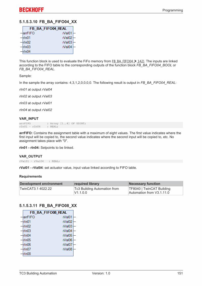
Programming
TC3 Building Automation 151Version: 1.0
5.1.5.3.10 FB_BA_FIFO04_XX
This function block is used to evaluate the FiFo memory from FB_BA_FIFO04 [} 142]. The inputs are linkedaccording to the FIFO table to the corresponding outputs of the function block FB_BA_FIFO04_BOOL orFB_BA_FIFO04_REAL.
Sample:
In the sample the array contains: 4,3,1,2,0,0,0,0. The following result is output in FB_BA_FIFO04_REAL:
rIn01 at output rVal04
rIn02 at output rVal03
rIn03 at output rVal01
rIn04 at output rVal02
VAR_INPUTarrFIFO : Array [1..4] OF UDINT;rIn01 – rIn04 : REAL;
arrFIFO: Contains the assignment table with a maximum of eight values. The first value indicates where thefirst input will be copied to, the second value indicates where the second input will be copied to, etc. Noassignment takes place with "0".
rIn01 - rIn04: Setpoints to be linked.
VAR_OUTPUTrVal01 – rVal04 : REAL;
rVal01 - rVal04: set actuator value, input value linked according to FIFO table.
Requirements
Development environment required library Necessary functionTwinCAT3.1 4022.22 Tc3 Building Automation from
V1.1.0.0TF8040 | TwinCAT BuildingAutomation from V3.1.11.0
5.1.5.3.11 FB_BA_FIFO08_XX
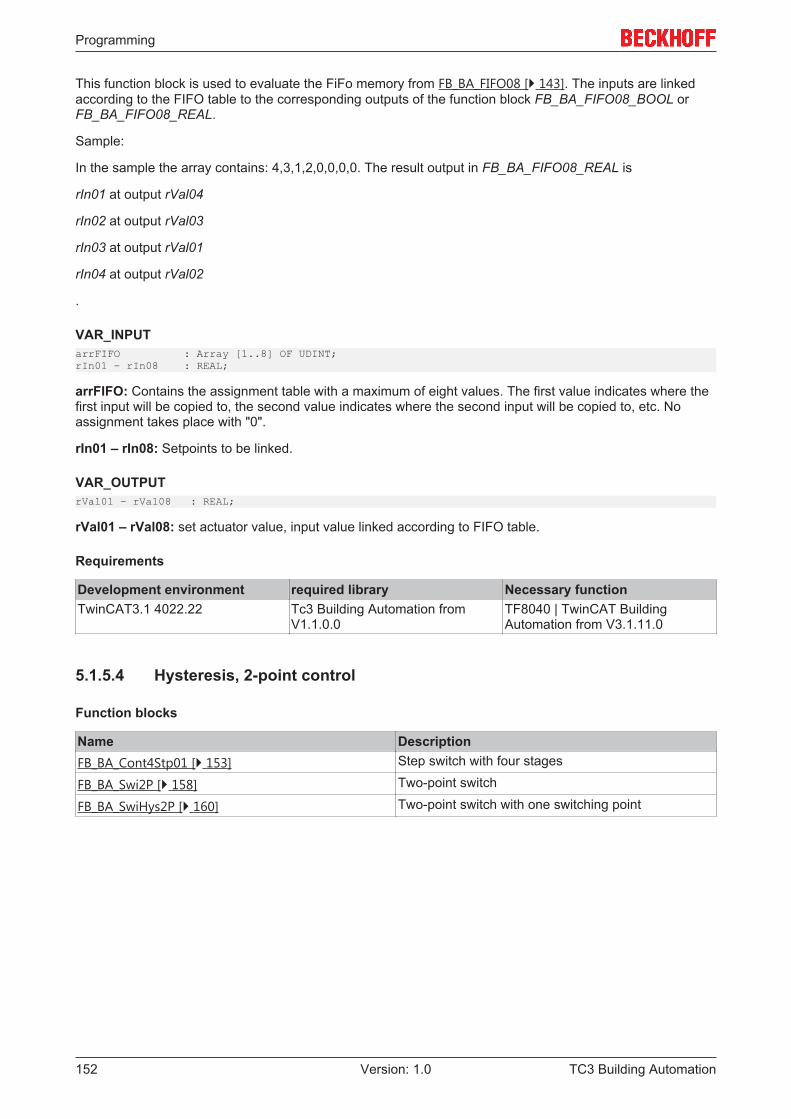
Programming
TC3 Building Automation152 Version: 1.0
This function block is used to evaluate the FiFo memory from FB_BA_FIFO08 [} 143]. The inputs are linkedaccording to the FIFO table to the corresponding outputs of the function block FB_BA_FIFO08_BOOL orFB_BA_FIFO08_REAL.
Sample:
In the sample the array contains: 4,3,1,2,0,0,0,0. The result output in FB_BA_FIFO08_REAL is
rIn01 at output rVal04
rIn02 at output rVal03
rIn03 at output rVal01
rIn04 at output rVal02
.
VAR_INPUTarrFIFO : Array [1..8] OF UDINT;rIn01 – rIn08 : REAL;
arrFIFO: Contains the assignment table with a maximum of eight values. The first value indicates where thefirst input will be copied to, the second value indicates where the second input will be copied to, etc. Noassignment takes place with "0".
rIn01 – rIn08: Setpoints to be linked.
VAR_OUTPUTrVal01 – rVal08 : REAL;
rVal01 – rVal08: set actuator value, input value linked according to FIFO table.
Requirements
Development environment required library Necessary functionTwinCAT3.1 4022.22 Tc3 Building Automation from
V1.1.0.0TF8040 | TwinCAT BuildingAutomation from V3.1.11.0
5.1.5.4 Hysteresis, 2-point control
Function blocks
Name DescriptionFB_BA_Cont4Stp01 [} 153] Step switch with four stages
FB_BA_Swi2P [} 158] Two-point switch
FB_BA_SwiHys2P [} 160] Two-point switch with one switching point
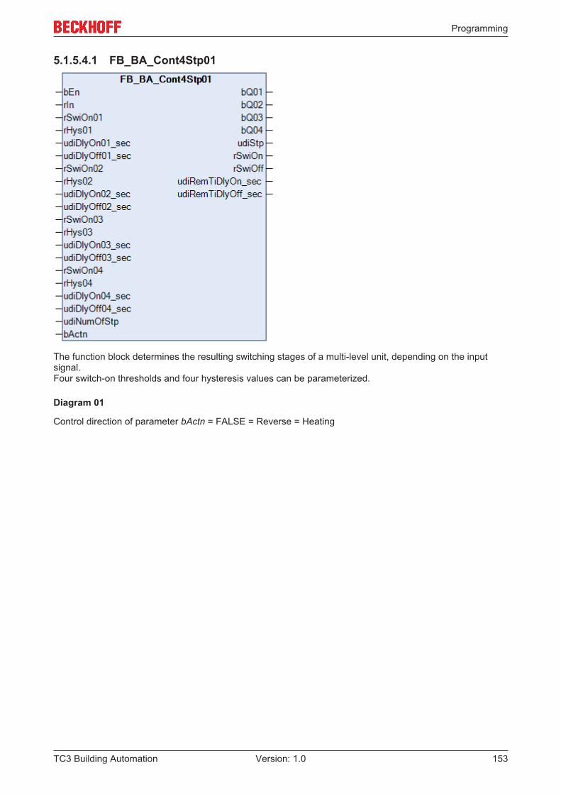
Programming
TC3 Building Automation 153Version: 1.0
5.1.5.4.1 FB_BA_Cont4Stp01
The function block determines the resulting switching stages of a multi-level unit, depending on the inputsignal.Four switch-on thresholds and four hysteresis values can be parameterized.
Diagram 01
Control direction of parameter bActn = FALSE = Reverse = Heating
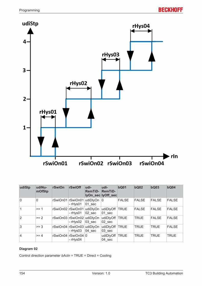
Programming
TC3 Building Automation154 Version: 1.0
udiStp udiNu-mOfStp
rSwiOn rSwiOff udi-RemTiD-lyOn_sec
udi-RemTiD-lyOff_sec
bQ01 bQ02 bQ03 bQ04
0 0 rSwiOn01 rSwiOn01- rHys01
udiDlyOn01_sec
0 FALSE FALSE FALSE FALSE
1 >= 1 rSwiOn02 rSwiOn01- rHys01
udiDlyOn02_sec
udiDlyOff01_sec
TRUE FALSE FALSE FALSE
2 >= 2 rSwiOn03 rSwiOn02- rHys02
udiDlyOn03_sec
udiDlyOff02_sec
TRUE TRUE FALSE FALSE
3 >= 3 rSwiOn04 rSwiOn03- rHys03
udiDlyOn04_sec
udiDlyOff03_sec
TRUE TRUE TRUE FALSE
4 >= 4 rSwiOn04 rSwiOn04- rHys04
0 udiDlyOff04_sec
TRUE TRUE TRUE TRUE
Diagram 02
Control direction parameter bActn = TRUE = Direct = Cooling
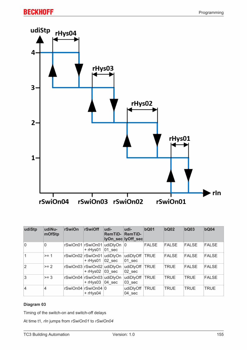
Programming
TC3 Building Automation 155Version: 1.0
udiStp udiNu-mOfStp
rSwiOn rSwiOff udi-RemTiD-lyOn_sec
udi-RemTiD-lyOff_sec
bQ01 bQ02 bQ03 bQ04
0 0 rSwiOn01 rSwiOn01+ rHys01
udiDlyOn01_sec
0 FALSE FALSE FALSE FALSE
1 >= 1 rSwiOn02 rSwiOn01+ rHys01
udiDlyOn02_sec
udiDlyOff01_sec
TRUE FALSE FALSE FALSE
2 >= 2 rSwiOn03 rSwiOn02+ rHys02
udiDlyOn03_sec
udiDlyOff02_sec
TRUE TRUE FALSE FALSE
3 >= 3 rSwiOn04 rSwiOn03+ rHys03
udiDlyOn04_sec
udiDlyOff03_sec
TRUE TRUE TRUE FALSE
4 4 rSwiOn04 rSwiOn04+ rHys04
0 udiDlyOff04_sec
TRUE TRUE TRUE TRUE
Diagram 03
Timing of the switch-on and switch-off delays
At time t1, rIn jumps from rSwiOn01 to rSwiOn04
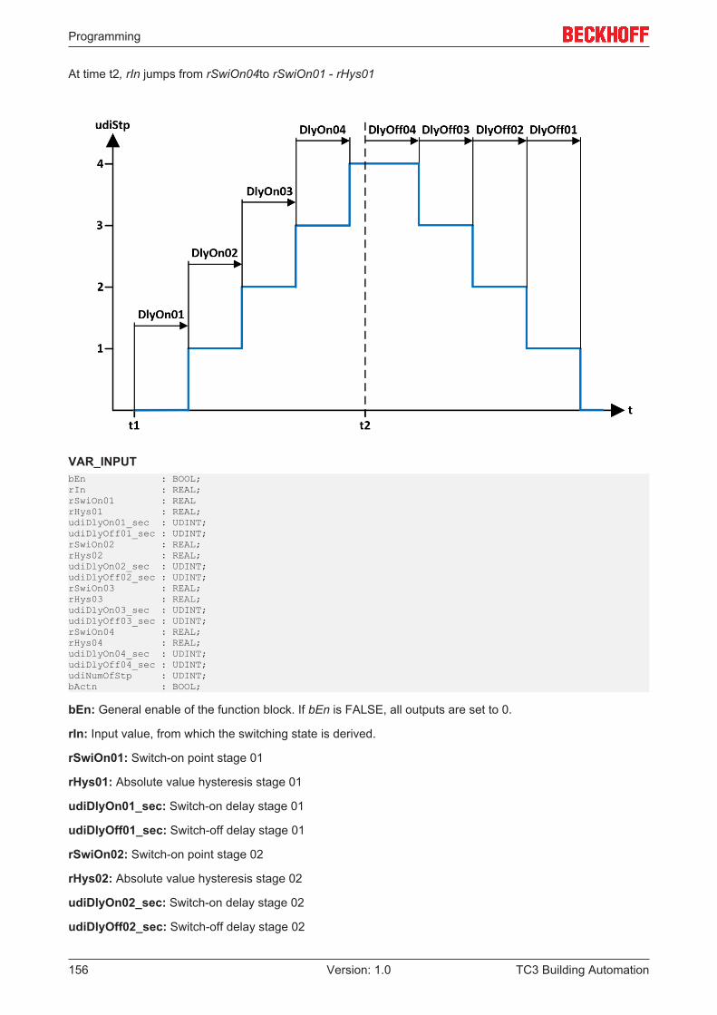
Programming
TC3 Building Automation156 Version: 1.0
At time t2, rIn jumps from rSwiOn04to rSwiOn01 - rHys01
VAR_INPUTbEn : BOOL;rIn : REAL;rSwiOn01 : REALrHys01 : REAL;udiDlyOn01_sec : UDINT;udiDlyOff01_sec : UDINT;rSwiOn02 : REAL;rHys02 : REAL;udiDlyOn02_sec : UDINT;udiDlyOff02_sec : UDINT;rSwiOn03 : REAL;rHys03 : REAL;udiDlyOn03_sec : UDINT;udiDlyOff03_sec : UDINT;rSwiOn04 : REAL;rHys04 : REAL;udiDlyOn04_sec : UDINT;udiDlyOff04_sec : UDINT;udiNumOfStp : UDINT;bActn : BOOL;
bEn: General enable of the function block. If bEn is FALSE, all outputs are set to 0.
rIn: Input value, from which the switching state is derived.
rSwiOn01: Switch-on point stage 01
rHys01: Absolute value hysteresis stage 01
udiDlyOn01_sec: Switch-on delay stage 01
udiDlyOff01_sec: Switch-off delay stage 01
rSwiOn02: Switch-on point stage 02
rHys02: Absolute value hysteresis stage 02
udiDlyOn02_sec: Switch-on delay stage 02
udiDlyOff02_sec: Switch-off delay stage 02
Programming
TC3 Building Automation 157Version: 1.0
rSwiOn03: Switch-on point stage 03
rHys03: Absolute value hysteresis stage 03
udiDlyOn03_sec: Switch-on delay stage 03
udiDlyOff03_sec: Switch-off delay stage 03
rSwiOn04: Switch-on point stage 04
rHys04: Absolute value hysteresis stage 04
udiDlyOn04_sec: Switch-on delay stage 04
udiDlyOff04_sec: Switch-off delay stage 04
udiNumOfStp: Number of stages that are required.The input is limited to a range from 0 to 4
bActn: Input variable used to determine the control direction of the step switch.TRUE = direct = cooling; FALSE = reverse = heating
VAR_OUTPUTbQ01 : BOOL;bQ02 : BOOL;bQ03 : BOOL;bQ04 : BOOL;udiStp : UDINT;rSwiOn : REAL;rSwiOff : REAL;udiRemTiDlyOn_sec : UDINT;udiRemTiDlyOff_sec : UDINT;
bQ01: Display of status step 01TRUE = ON; FALSE = OFFudiStp >= 1
bQ02: Display of status step 02TRUE = ON; FALSE = OFFudiStp >= 2
bQ03: Display of status step 03TRUE = ON; FALSE = OFFudiStp >= 3
bQ04: Display of status step 04TRUE = ON; FALSE = OFFudiStp >= 4
udiStp: Shows the current step of the step switch
rSwiOn: Shows the next switch-on point
rSwiOff: Shows the next switch-off point
udiRemTiDlyOn_sec: If the switch-on point for switching to the next level is met, the progress of the switch-on delay time is displayed here.
udiRemTiDlyOff_sec: If the switch-off point for switching down to the next level is met, the progress of theswitch-off delay time is displayed here.
Requirements
Development environment required library Necessary functionTwinCAT3.1 4022.22 Tc3 Building Automation from
V1.1.0.0TF8040 | TwinCAT BuildingAutomation from V3.1.11.0
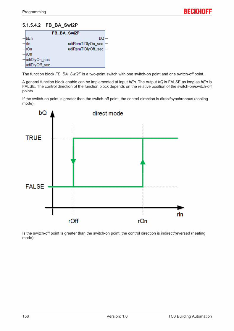
Programming
TC3 Building Automation158 Version: 1.0
5.1.5.4.2 FB_BA_Swi2P
The function block FB_BA_Swi2P is a two-point switch with one switch-on point and one switch-off point.
A general function block enable can be implemented at input bEn. The output bQ is FALSE as long as bEn isFALSE. The control direction of the function block depends on the relative position of the switch-on/switch-offpoints.
If the switch-on point is greater than the switch-off point, the control direction is direct/synchronous (coolingmode).
Is the switch-off point is greater than the switch-on point, the control direction is indirect/reversed (heatingmode).
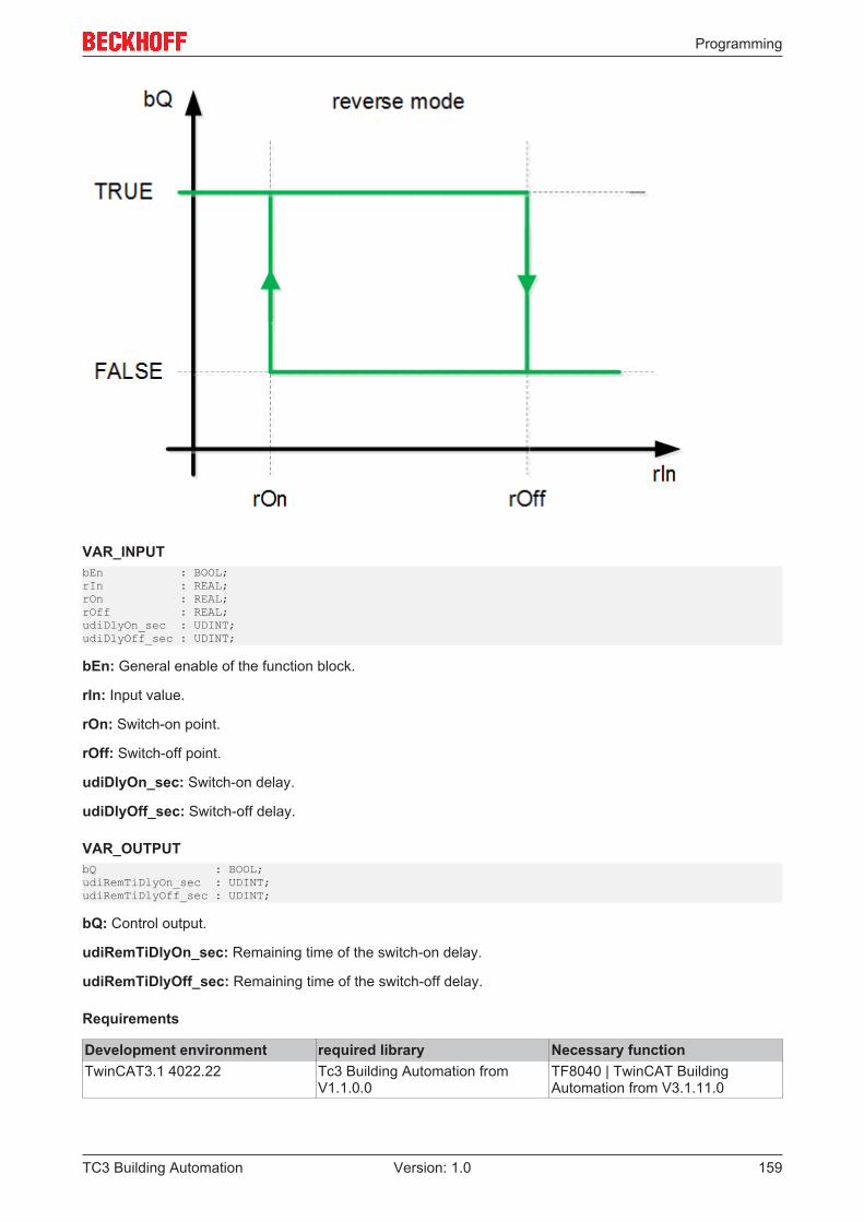
Programming
TC3 Building Automation 159Version: 1.0
VAR_INPUTbEn : BOOL;rIn : REAL;rOn : REAL;rOff : REAL;udiDlyOn_sec : UDINT;udiDlyOff_sec : UDINT;
bEn: General enable of the function block.
rIn: Input value.
rOn: Switch-on point.
rOff: Switch-off point.
udiDlyOn_sec: Switch-on delay.
udiDlyOff_sec: Switch-off delay.
VAR_OUTPUTbQ : BOOL;udiRemTiDlyOn_sec : UDINT;udiRemTiDlyOff_sec : UDINT;
bQ: Control output.
udiRemTiDlyOn_sec: Remaining time of the switch-on delay.
udiRemTiDlyOff_sec: Remaining time of the switch-off delay.
Requirements
Development environment required library Necessary functionTwinCAT3.1 4022.22 Tc3 Building Automation from
V1.1.0.0TF8040 | TwinCAT BuildingAutomation from V3.1.11.0
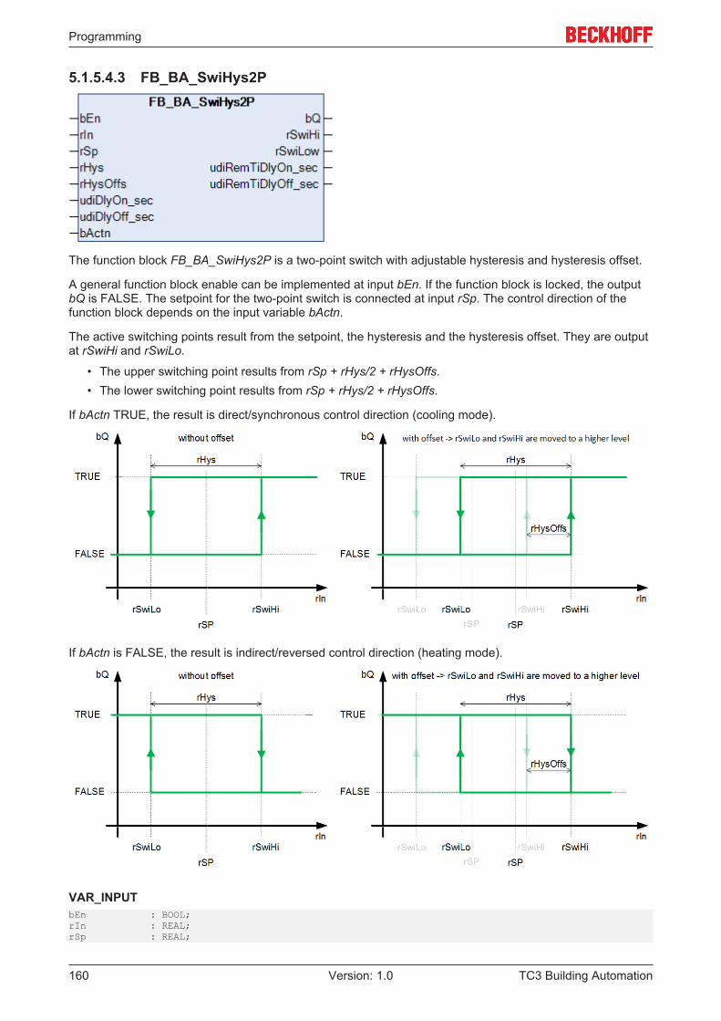
Programming
TC3 Building Automation160 Version: 1.0
5.1.5.4.3 FB_BA_SwiHys2P
The function block FB_BA_SwiHys2P is a two-point switch with adjustable hysteresis and hysteresis offset.
A general function block enable can be implemented at input bEn. If the function block is locked, the outputbQ is FALSE. The setpoint for the two-point switch is connected at input rSp. The control direction of thefunction block depends on the input variable bActn.
The active switching points result from the setpoint, the hysteresis and the hysteresis offset. They are outputat rSwiHi and rSwiLo.
• The upper switching point results from rSp + rHys/2 + rHysOffs.• The lower switching point results from rSp + rHys/2 + rHysOffs.
If bActn TRUE, the result is direct/synchronous control direction (cooling mode).
If bActn is FALSE, the result is indirect/reversed control direction (heating mode).
VAR_INPUTbEn : BOOL;rIn : REAL;rSp : REAL;
Programming
TC3 Building Automation 161Version: 1.0
rHys : REAL;rHysOffs : REAL;udiDlyOn_sec : UDINT;udiDlyOff_sec : UDINT;bActn : BOOL;
bEn: General enable of the function block.
rIn: Input value.
rSp: Setpoint input.
rHys: Hysteresis.
rHysOffs: Hysteresis offset.
udiDlyOn_sec: Switch-on delay
udiDlyOff_sec: Release delay
bActn: Control direction.
VAR_OUTPUTbQ : BOOL;rSwiHi : REAL;rSwiLo : REAL;udiRemTiDlyOn_sec : UDINT;udiRemTiDlyOff_sec : UDINT;
bQ: Output.
rSwiHi: Upper switching point.
rSwiLo: Lower switching point.
udiRemTiDlyOn_sec: Time remaining before switching on.
udiRemTiDlyOff_sec: Time remaining before switching off.
Requirements
Development environment required library Necessary functionTwinCAT3.1 4022.22 Tc3 Building Automation from
V1.1.0.0TF8040 | TwinCAT BuildingAutomation from V3.1.11.0
5.1.5.5 Mathematical functions
Function blocks
Name DescriptionFB_BA_MultiCalc_XX [} 162] Multi-calculation function blocks
FB_BA_Chrct02 [} 163] Linear interpolation for 2 interpolation points
FB_BA_Chrct04 [} 165] Linear interpolation for 4 interpolation points
FB_BA_Chrct07 [} 166] Linear interpolation for 7 interpolation points
FB_BA_Chrct32 [} 168] Linear interpolation for 32 interpolation points
FB_BA_TiAvrg [} 169] Arithmetic mean value over time
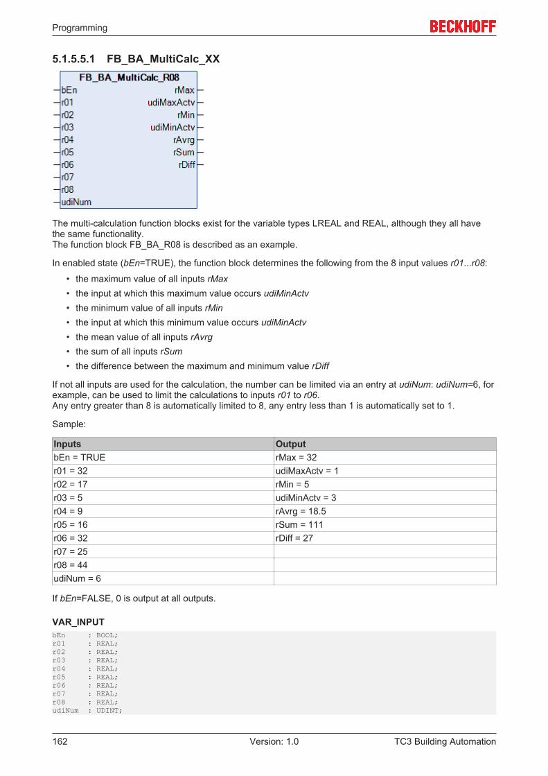
Programming
TC3 Building Automation162 Version: 1.0
5.1.5.5.1 FB_BA_MultiCalc_XX
The multi-calculation function blocks exist for the variable types LREAL and REAL, although they all havethe same functionality.The function block FB_BA_R08 is described as an example.
In enabled state (bEn=TRUE), the function block determines the following from the 8 input values r01...r08:
• the maximum value of all inputs rMax• the input at which this maximum value occurs udiMinActv• the minimum value of all inputs rMin• the input at which this minimum value occurs udiMinActv• the mean value of all inputs rAvrg• the sum of all inputs rSum• the difference between the maximum and minimum value rDiff
If not all inputs are used for the calculation, the number can be limited via an entry at udiNum: udiNum=6, forexample, can be used to limit the calculations to inputs r01 to r06.Any entry greater than 8 is automatically limited to 8, any entry less than 1 is automatically set to 1.
Sample:
Inputs OutputbEn = TRUE rMax = 32r01 = 32 udiMaxActv = 1r02 = 17 rMin = 5r03 = 5 udiMinActv = 3r04 = 9 rAvrg = 18.5r05 = 16 rSum = 111r06 = 32 rDiff = 27r07 = 25r08 = 44udiNum = 6
If bEn=FALSE, 0 is output at all outputs.
VAR_INPUTbEn : BOOL;r01 : REAL;r02 : REAL;r03 : REAL;r04 : REAL;r05 : REAL;r06 : REAL;r07 : REAL;r08 : REAL;udiNum : UDINT;
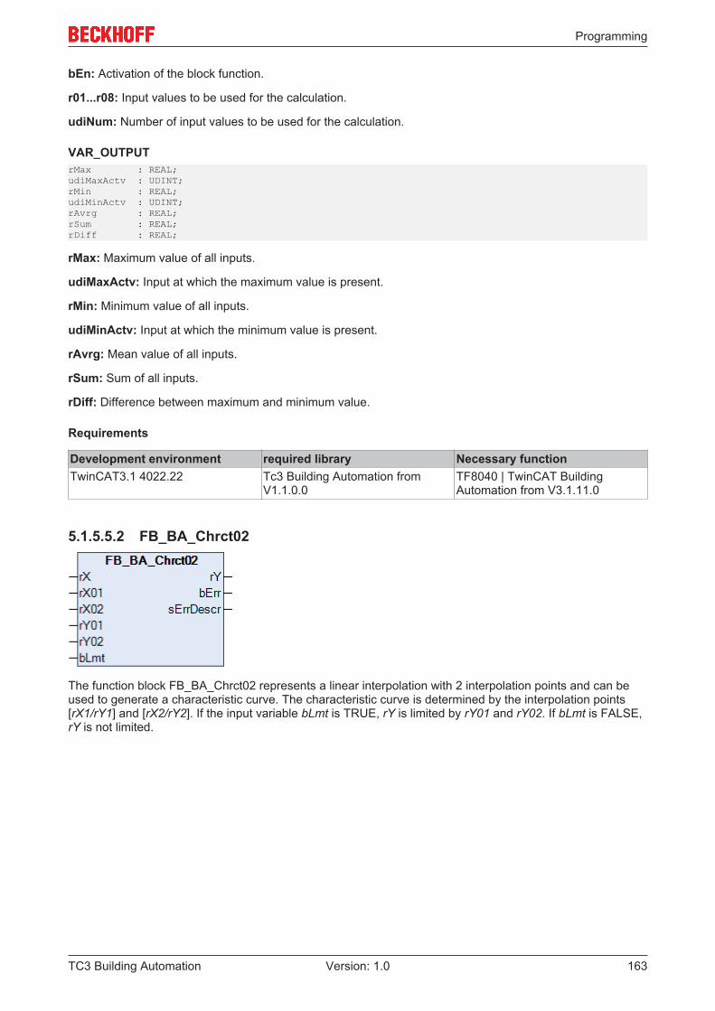
Programming
TC3 Building Automation 163Version: 1.0
bEn: Activation of the block function.
r01...r08: Input values to be used for the calculation.
udiNum: Number of input values to be used for the calculation.
VAR_OUTPUTrMax : REAL;udiMaxActv : UDINT;rMin : REAL;udiMinActv : UDINT;rAvrg : REAL;rSum : REAL;rDiff : REAL;
rMax: Maximum value of all inputs.
udiMaxActv: Input at which the maximum value is present.
rMin: Minimum value of all inputs.
udiMinActv: Input at which the minimum value is present.
rAvrg: Mean value of all inputs.
rSum: Sum of all inputs.
rDiff: Difference between maximum and minimum value.
Requirements
Development environment required library Necessary functionTwinCAT3.1 4022.22 Tc3 Building Automation from
V1.1.0.0TF8040 | TwinCAT BuildingAutomation from V3.1.11.0
5.1.5.5.2 FB_BA_Chrct02
The function block FB_BA_Chrct02 represents a linear interpolation with 2 interpolation points and can beused to generate a characteristic curve. The characteristic curve is determined by the interpolation points[rX1/rY1] and [rX2/rY2]. If the input variable bLmt is TRUE, rY is limited by rY01 and rY02. If bLmt is FALSE,rY is not limited.
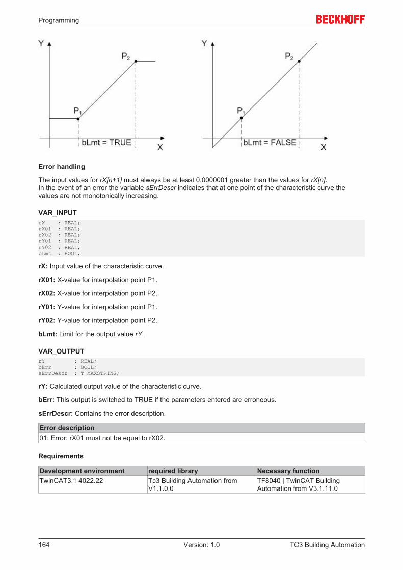
Programming
TC3 Building Automation164 Version: 1.0
Error handling
The input values for rX[n+1] must always be at least 0.0000001 greater than the values for rX[n].In the event of an error the variable sErrDescr indicates that at one point of the characteristic curve thevalues are not monotonically increasing.
VAR_INPUTrX : REAL;rX01 : REAL;rX02 : REAL;rY01 : REAL;rY02 : REAL;bLmt : BOOL;
rX: Input value of the characteristic curve.
rX01: X-value for interpolation point P1.
rX02: X-value for interpolation point P2.
rY01: Y-value for interpolation point P1.
rY02: Y-value for interpolation point P2.
bLmt: Limit for the output value rY.
VAR_OUTPUTrY : REAL;bErr : BOOL;sErrDescr : T_MAXSTRING;
rY: Calculated output value of the characteristic curve.
bErr: This output is switched to TRUE if the parameters entered are erroneous.
sErrDescr: Contains the error description.
Error description01: Error: rX01 must not be equal to rX02.
Requirements
Development environment required library Necessary functionTwinCAT3.1 4022.22 Tc3 Building Automation from
V1.1.0.0TF8040 | TwinCAT BuildingAutomation from V3.1.11.0
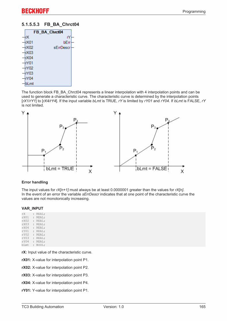
Programming
TC3 Building Automation 165Version: 1.0
5.1.5.5.3 FB_BA_Chrct04
The function block FB_BA_Chrct04 represents a linear interpolation with 4 interpolation points and can beused to generate a characteristic curve. The characteristic curve is determined by the interpolation points[rX1/rY1] to [rX4/rY4]. If the input variable bLmt is TRUE, rY is limited by rY01 and rY04. If bLmt is FALSE, rYis not limited.
Error handling
The input values for rX[n+1] must always be at least 0.0000001 greater than the values for rX[n].In the event of an error the variable sErrDescr indicates that at one point of the characteristic curve thevalues are not monotonically increasing.
VAR_INPUTrX : REAL;rX01 : REAL;rX02 : REAL;rX03 : REAL;rX04 : REAL;rY01 : REAL;rY02 : REAL;rY03 : REAL;rY04 : REAL;bLmt : BOOL;
rX: Input value of the characteristic curve.
rX01: X-value for interpolation point P1.
rX02: X-value for interpolation point P2.
rX03: X-value for interpolation point P3.
rX04: X-value for interpolation point P4.
rY01: Y-value for interpolation point P1.
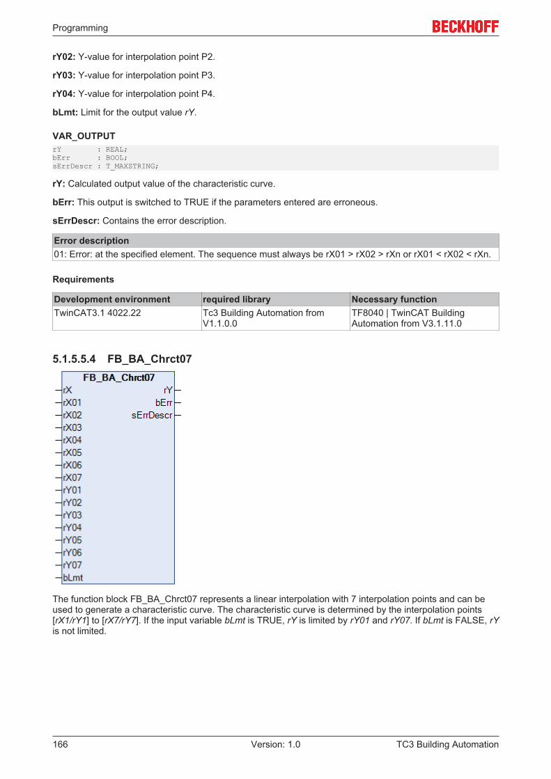
Programming
TC3 Building Automation166 Version: 1.0
rY02: Y-value for interpolation point P2.
rY03: Y-value for interpolation point P3.
rY04: Y-value for interpolation point P4.
bLmt: Limit for the output value rY.
VAR_OUTPUTrY : REAL;bErr : BOOL;sErrDescr : T_MAXSTRING;
rY: Calculated output value of the characteristic curve.
bErr: This output is switched to TRUE if the parameters entered are erroneous.
sErrDescr: Contains the error description.
Error description01: Error: at the specified element. The sequence must always be rX01 > rX02 > rXn or rX01 < rX02 < rXn.
Requirements
Development environment required library Necessary functionTwinCAT3.1 4022.22 Tc3 Building Automation from
V1.1.0.0TF8040 | TwinCAT BuildingAutomation from V3.1.11.0
5.1.5.5.4 FB_BA_Chrct07
The function block FB_BA_Chrct07 represents a linear interpolation with 7 interpolation points and can beused to generate a characteristic curve. The characteristic curve is determined by the interpolation points[rX1/rY1] to [rX7/rY7]. If the input variable bLmt is TRUE, rY is limited by rY01 and rY07. If bLmt is FALSE, rYis not limited.
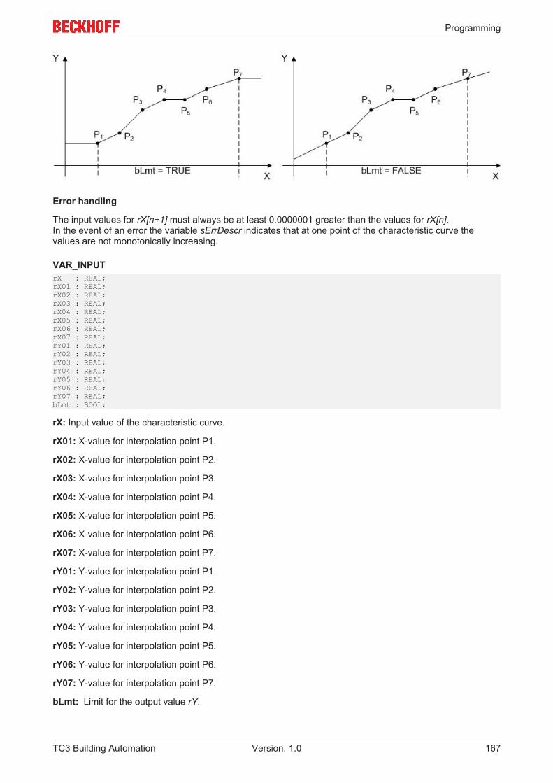
Programming
TC3 Building Automation 167Version: 1.0
Error handling
The input values for rX[n+1] must always be at least 0.0000001 greater than the values for rX[n].In the event of an error the variable sErrDescr indicates that at one point of the characteristic curve thevalues are not monotonically increasing.
VAR_INPUTrX : REAL;rX01 : REAL;rX02 : REAL;rX03 : REAL;rX04 : REAL;rX05 : REAL;rX06 : REAL;rX07 : REAL;rY01 : REAL;rY02 : REAL;rY03 : REAL;rY04 : REAL;rY05 : REAL;rY06 : REAL;rY07 : REAL;bLmt : BOOL;
rX: Input value of the characteristic curve.
rX01: X-value for interpolation point P1.
rX02: X-value for interpolation point P2.
rX03: X-value for interpolation point P3.
rX04: X-value for interpolation point P4.
rX05: X-value for interpolation point P5.
rX06: X-value for interpolation point P6.
rX07: X-value for interpolation point P7.
rY01: Y-value for interpolation point P1.
rY02: Y-value for interpolation point P2.
rY03: Y-value for interpolation point P3.
rY04: Y-value for interpolation point P4.
rY05: Y-value for interpolation point P5.
rY06: Y-value for interpolation point P6.
rY07: Y-value for interpolation point P7.
bLmt: Limit for the output value rY.
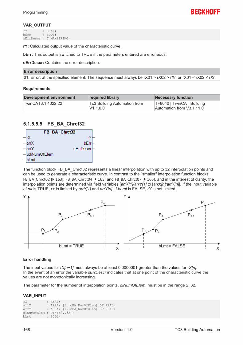
Programming
TC3 Building Automation168 Version: 1.0
VAR_OUTPUTrY : REAL;bErr : BOOL;sErrDescr : T_MAXSTRING;
rY: Calculated output value of the characteristic curve.
bErr: This output is switched to TRUE if the parameters entered are erroneous.
sErrDescr: Contains the error description.
Error description01: Error: at the specified element. The sequence must always be rX01 > rX02 > rXn or rX01 < rX02 < rXn.
Requirements
Development environment required library Necessary functionTwinCAT3.1 4022.22 Tc3 Building Automation from
V1.1.0.0TF8040 | TwinCAT BuildingAutomation from V3.1.11.0
5.1.5.5.5 FB_BA_Chrct32
The function block FB_BA_Chrct32 represents a linear interpolation with up to 32 interpolation points andcan be used to generate a characteristic curve. In contrast to the "smaller" interpolation function blocksFB_BA_Chrct02 [} 163], FB_BA_Chrct04 [} 165] and FB_BA_Chrct07 [} 166], and in the interest of clarity, theinterpolation points are determined via field variables [arrX[1]/arrY[1] to [arrX[n]/arrY[n]]. If the input variablebLmt is TRUE, rY is limited by arrY[1] and arrY[n]. If bLmt is FALSE, rY is not limited.
Error handling
The input values for rX[n+1] must always be at least 0.0000001 greater than the values for rX[n].In the event of an error the variable sErrDescr indicates that at one point of the characteristic curve thevalues are not monotonically increasing.
The parameter for the number of interpolation points, diNumOfElem, must be in the range 2..32.
VAR_INPUTrX : REAL;arrX : ARRAY [1..cBA_NumOfElem] OF REAL;arrY : ARRAY [1..cBA_NumOfElem] OF REAL;diNumOfElem : DINT(2..32);bLmt : BOOL;
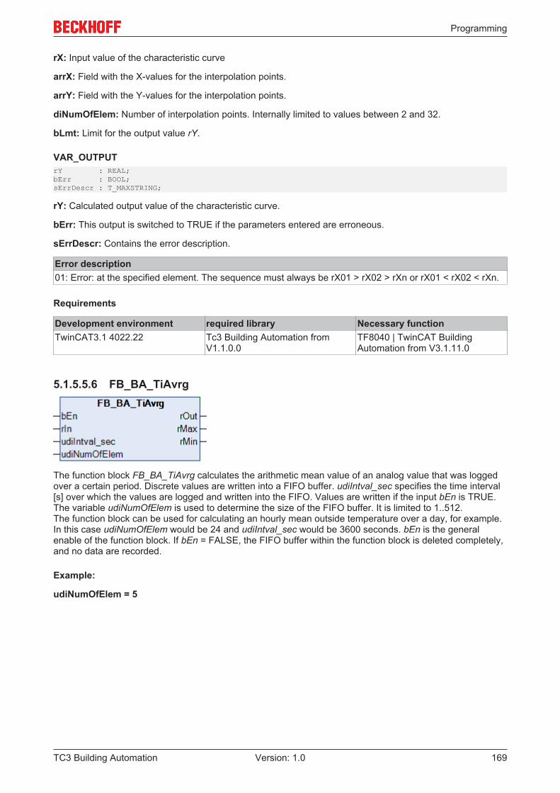
Programming
TC3 Building Automation 169Version: 1.0
rX: Input value of the characteristic curve
arrX: Field with the X-values for the interpolation points.
arrY: Field with the Y-values for the interpolation points.
diNumOfElem: Number of interpolation points. Internally limited to values between 2 and 32.
bLmt: Limit for the output value rY.
VAR_OUTPUTrY : REAL;bErr : BOOL;sErrDescr : T_MAXSTRING;
rY: Calculated output value of the characteristic curve.
bErr: This output is switched to TRUE if the parameters entered are erroneous.
sErrDescr: Contains the error description.
Error description01: Error: at the specified element. The sequence must always be rX01 > rX02 > rXn or rX01 < rX02 < rXn.
Requirements
Development environment required library Necessary functionTwinCAT3.1 4022.22 Tc3 Building Automation from
V1.1.0.0TF8040 | TwinCAT BuildingAutomation from V3.1.11.0
5.1.5.5.6 FB_BA_TiAvrg
The function block FB_BA_TiAvrg calculates the arithmetic mean value of an analog value that was loggedover a certain period. Discrete values are written into a FIFO buffer. udiIntval_sec specifies the time interval[s] over which the values are logged and written into the FIFO. Values are written if the input bEn is TRUE.The variable udiNumOfElem is used to determine the size of the FIFO buffer. It is limited to 1..512.The function block can be used for calculating an hourly mean outside temperature over a day, for example.In this case udiNumOfElem would be 24 and udiIntval_sec would be 3600 seconds. bEn is the generalenable of the function block. If bEn = FALSE, the FIFO buffer within the function block is deleted completely,and no data are recorded.
Example:
udiNumOfElem = 5
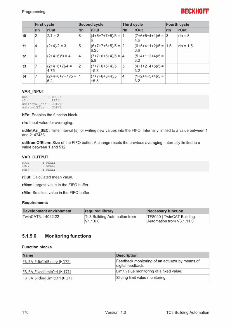
Programming
TC3 Building Automation170 Version: 1.0
First cycle Second cycle Third cycle Fourth cyclerIn rOut rIn rOut rIn rOut rIn rOut
t0 2 2/1 = 2 6 (4+6+7+7+6)/5 =6
1 (7+6+5+4+1)/5 =4.6
3 rIn = 3
t1 4 (2+4)/2 = 3 5 (6+7+7+6+5)/5 =6.25
2 (6+5+4+1+2)/5 =3.6
1.5 rIn = 1.5
t2 6 (2+4+6)/3 = 4 4 (7+7+6+5+4)/5 =5.8
4 (5+4+1+2+4)/5 =3.2
t3 7 (2+4+6+7)/4 =4.75
2 (7+7+6+5+4)/5=5.8
5 (4+1+2+4+5)/5 =3.2
t4 7 (2+4+6+7+7)/5 =5.2
1 (7+7+6+5+4)/5=5.8
4 (1+2+4+5+4)/5 =3.2
VAR_INPUTbEn : BOOL;rIn : REAL;udiIntval_sec : UDINT;udiNumOfElem : UDINT;
bEn: Enables the function block.
rIn: Input value for averaging.
udiIntVal_SEC: Time interval [s] for writing new values into the FIFO. Internally limited to a value between 1and 2147483.
udiNumOfElem: Size of the FIFO buffer. A change resets the previous averaging. Internally limited to avalue between 1 and 512.
VAR_OUTPUTrOut : REAL;rMax : REAL;rMin : REAL;
rOut: Calculated mean value.
rMax: Largest value in the FIFO buffer.
rMin: Smallest value in the FIFO buffer.
Requirements
Development environment required library Necessary functionTwinCAT3.1 4022.22 Tc3 Building Automation from
V1.1.0.0TF8040 | TwinCAT BuildingAutomation from V3.1.11.0
5.1.5.6 Monitoring functions
Function blocks
Name DescriptionFB_BA_FdbCtrlBinary [} 172] Feedback monitoring of an actuator by means of
digital feedback.FB_BA_FixedLimitCtrl [} 171] Limit value monitoring of a fixed value.
FB_BA_SlidingLimitCtrl [} 173] Sliding limit value monitoring.
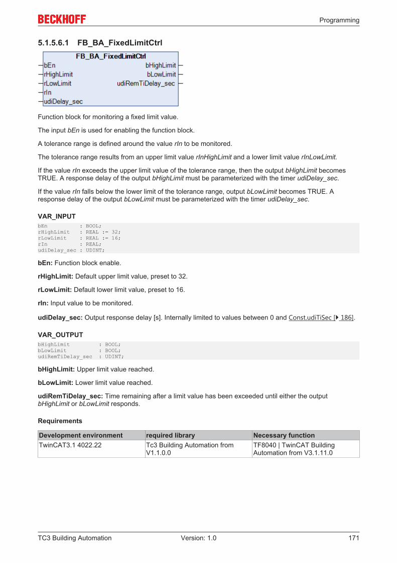
Programming
TC3 Building Automation 171Version: 1.0
5.1.5.6.1 FB_BA_FixedLimitCtrl
Function block for monitoring a fixed limit value.
The input bEn is used for enabling the function block.
A tolerance range is defined around the value rIn to be monitored.
The tolerance range results from an upper limit value rInHighLimit and a lower limit value rInLowLimit.
If the value rIn exceeds the upper limit value of the tolerance range, then the output bHighLimit becomesTRUE. A response delay of the output bHighLimit must be parameterized with the timer udiDelay_sec.
If the value rIn falls below the lower limit of the tolerance range, output bLowLimit becomes TRUE. Aresponse delay of the output bLowLimit must be parameterized with the timer udiDelay_sec.
VAR_INPUTbEn : BOOL;rHighLimit : REAL := 32;rLowLimit : REAL := 16;rIn : REAL;udiDelay_sec : UDINT;
bEn: Function block enable.
rHighLimit: Default upper limit value, preset to 32.
rLowLimit: Default lower limit value, preset to 16.
rIn: Input value to be monitored.
udiDelay_sec: Output response delay [s]. Internally limited to values between 0 and Const.udiTiSec [} 186].
VAR_OUTPUTbHighLimit : BOOL;bLowLimit : BOOL;udiRemTiDelay_sec : UDINT;
bHighLimit: Upper limit value reached.
bLowLimit: Lower limit value reached.
udiRemTiDelay_sec: Time remaining after a limit value has been exceeded until either the outputbHighLimit or bLowLimit responds.
Requirements
Development environment required library Necessary functionTwinCAT3.1 4022.22 Tc3 Building Automation from
V1.1.0.0TF8040 | TwinCAT BuildingAutomation from V3.1.11.0
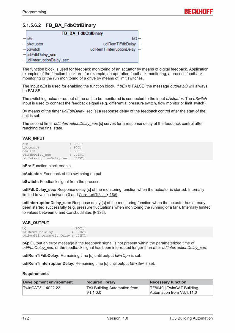
Programming
TC3 Building Automation172 Version: 1.0
5.1.5.6.2 FB_BA_FdbCtrlBinary
The function block is used for feedback monitoring of an actuator by means of digital feedback. Applicationexamples of the function block are, for example, an operation feedback monitoring, a process feedbackmonitoring or the run monitoring of a drive by means of limit switches.
The input bEn is used for enabling the function block. If bEn is FALSE, the message output bQ will alwaysbe FALSE.
The switching actuator output of the unit to be monitored is connected to the input bActuator. The bSwitchinput is used to connect the feedback signal (e.g. differential pressure switch, flow monitor or limit switch).
By means of the timer udiFdbDelay_sec [s] a response delay of the feedback control after the start of theunit is set.
The second timer udiInterruptionDelay_sec [s] serves for a response delay of the feedback control afterreaching the final state.
VAR_INPUTbEn : BOOL;bActuator : BOOL;bSwitch : BOOL;udiFdbDelay_sec : UDINT;udiInterruptionDelay_sec : UDINT;
bEn: Function block enable.
bActuator: Feedback of the switching output.
bSwitch: Feedback signal from the process.
udiFdbDelay_sec: Response delay [s] of the monitoring function when the actuator is started. Internallylimited to values between 0 and Const.udiTiSec [} 186].
udiInterruptionDelay_sec: Response delay [s] of the monitoring function when the actuator has alreadybeen started successfully (e.g. pressure fluctuations when monitoring the running of a fan). Internally limitedto values between 0 and Const.udiTiSec [} 186].
VAR_OUTPUTbQ : BOOL;udiRemTiFdbDelay : UDINT;udiRemTiInterruptionDelay : UDINT;
bQ: Output an error message if the feedback signal is not present within the parameterized time ofudiFdbDelay_sec, or the feedback signal has been interrupted longer than after udiInterruptionDelay_sec.
udiRemTiFdbDelay: Remaining time [s] until output bErrOpn is set.
udiRemTiInterruptionDelay: Remaining time [s] until output bErrSwi is set.
Requirements
Development environment required library Necessary functionTwinCAT3.1 4022.22 Tc3 Building Automation from
V1.1.0.0TF8040 | TwinCAT BuildingAutomation from V3.1.11.0
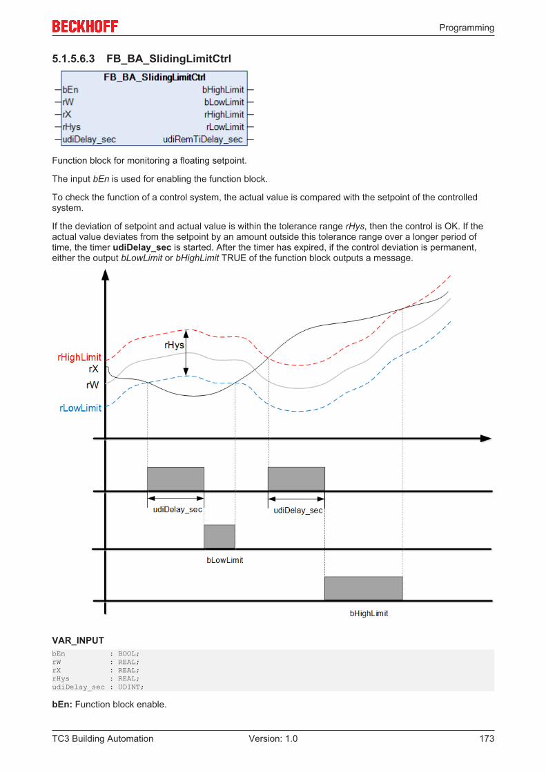
Programming
TC3 Building Automation 173Version: 1.0
5.1.5.6.3 FB_BA_SlidingLimitCtrl
Function block for monitoring a floating setpoint.
The input bEn is used for enabling the function block.
To check the function of a control system, the actual value is compared with the setpoint of the controlledsystem.
If the deviation of setpoint and actual value is within the tolerance range rHys, then the control is OK. If theactual value deviates from the setpoint by an amount outside this tolerance range over a longer period oftime, the timer udiDelay_sec is started. After the timer has expired, if the control deviation is permanent,either the output bLowLimit or bHighLimit TRUE of the function block outputs a message.
VAR_INPUTbEn : BOOL;rW : REAL;rX : REAL;rHys : REAL;udiDelay_sec : UDINT;
bEn: Function block enable.
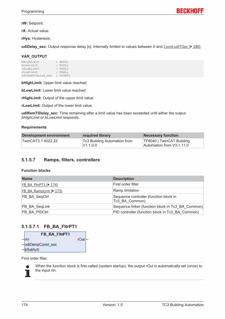
Programming
TC3 Building Automation174 Version: 1.0
rW: Setpoint.
rX: Actual value.
rHys: Hysteresis.
udiDelay_sec: Output response delay [s]. Internally limited to values between 0 and Const.udiTiSec [} 186].
VAR_OUTPUTbHighLimit : BOOL;bLowLimit : BOOL;rHighLimit : REAL;rLowLimit : REAL;udiRemTiDelay_sec : UDINT;
bHighLimit: Upper limit value reached.
bLowLimit: Lower limit value reached.
rHighLimit: Output of the upper limit value.
rLowLimit: Output of the lower limit value.
udiRemTiDelay_sec: Time remaining after a limit value has been exceeded until either the outputbHighLimit or bLowLimit responds.
Requirements
Development environment required library Necessary functionTwinCAT3.1 4022.22 Tc3 Building Automation from
V1.1.0.0TF8040 | TwinCAT BuildingAutomation from V3.1.11.0
5.1.5.7 Ramps, filters, controllers
Function blocks
Name DescriptionFB_BA_FltrPT1 [} 174] First order filter
FB_BA_RampLmt [} 175] Ramp limitationFB_BA_SeqCtrl Sequence controller (function block in
Tc3_BA_Common)FB_BA_SeqLink Sequence linker (function block in Tc3_BA_Common)FB_BA_PIDCtrl PID controller (function block in Tc3_BA_Common)
5.1.5.7.1 FB_BA_FltrPT1
First order filter.
When the function block is first called (system startup), the output rOut is automatically set (once) tothe input rIn.
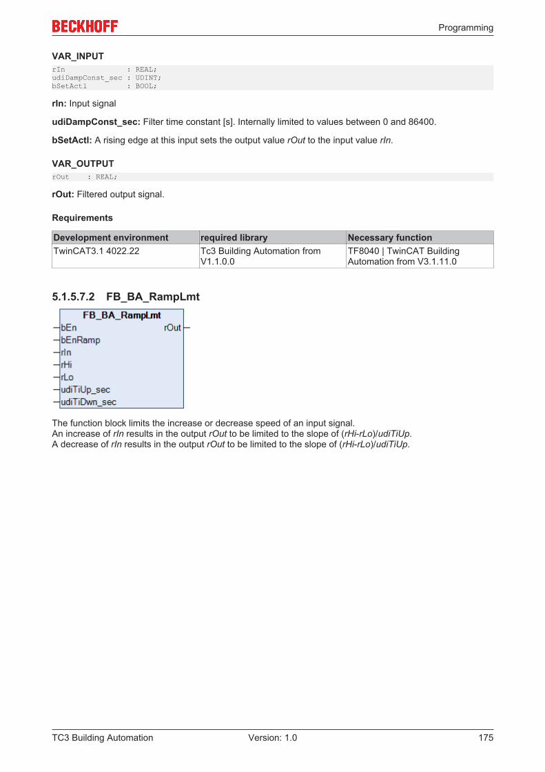
Programming
TC3 Building Automation 175Version: 1.0
VAR_INPUTrIn : REAL;udiDampConst_sec : UDINT;bSetActl : BOOL;
rIn: Input signal
udiDampConst_sec: Filter time constant [s]. Internally limited to values between 0 and 86400.
bSetActl: A rising edge at this input sets the output value rOut to the input value rIn.
VAR_OUTPUTrOut : REAL;
rOut: Filtered output signal.
Requirements
Development environment required library Necessary functionTwinCAT3.1 4022.22 Tc3 Building Automation from
V1.1.0.0TF8040 | TwinCAT BuildingAutomation from V3.1.11.0
5.1.5.7.2 FB_BA_RampLmt
The function block limits the increase or decrease speed of an input signal.An increase of rIn results in the output rOut to be limited to the slope of (rHi-rLo)/udiTiUp.A decrease of rIn results in the output rOut to be limited to the slope of (rHi-rLo)/udiTiUp.
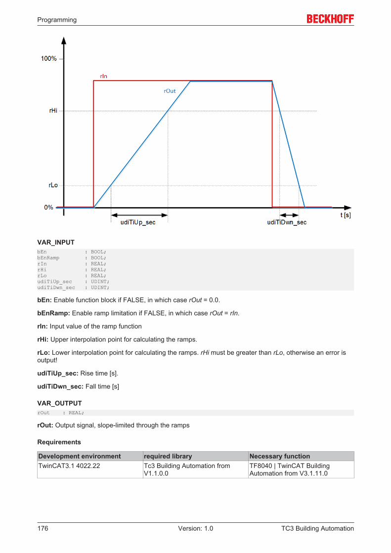
Programming
TC3 Building Automation176 Version: 1.0
VAR_INPUTbEn : BOOL;bEnRamp : BOOL;rIn : REAL;rHi : REAL;rLo : REAL;udiTiUp_sec : UDINT;udiTiDwn_sec : UDINT;
bEn: Enable function block if FALSE, in which case rOut = 0.0.
bEnRamp: Enable ramp limitation if FALSE, in which case rOut = rIn.
rIn: Input value of the ramp function
rHi: Upper interpolation point for calculating the ramps.
rLo: Lower interpolation point for calculating the ramps. rHi must be greater than rLo, otherwise an error isoutput!
udiTiUp_sec: Rise time [s].
udiTiDwn_sec: Fall time [s]
VAR_OUTPUTrOut : REAL;
rOut: Output signal, slope-limited through the ramps
Requirements
Development environment required library Necessary functionTwinCAT3.1 4022.22 Tc3 Building Automation from
V1.1.0.0TF8040 | TwinCAT BuildingAutomation from V3.1.11.0
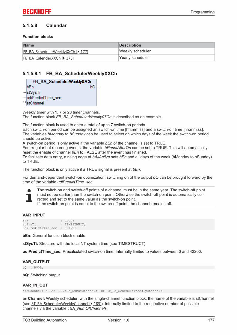
Programming
TC3 Building Automation 177Version: 1.0
5.1.5.8 Calendar
Function blocks
Name DescriptionFB_BA_SchedulerWeeklyXXCh [} 177] Weekly scheduler
FB_BA_CalenderXXCh [} 178] Yearly scheduler
5.1.5.8.1 FB_BA_SchedulerWeeklyXXCh
Weekly timer with 1, 7 or 28 timer channels.The function block FB_BA_SchedulerWeekly07Ch is described as an example.
The function block is used to enter a total of up to 7 switch-on periods.Each switch-on period can be assigned an switch-on time [hh:mm:ss] and a switch-off time [hh:mm:ss].The variables bMonday to bSunday can be used to select on which days of the week the switch-on periodshould be active.A switch-on period is only active if the variable bEn of the channel is set to TRUE.For irregular but recurring events, the variable bResetAfterOn can be set to TRUE. This will automaticallyreset the enable of channel bEn to FALSE after the event has finished.To facilitate data entry, a rising edge at bAllActive sets bEn and all days of the week (bMonday to bSunday)to TRUE.
The function block is only active if a TRUE signal is present at bEn.
For demand-dependent switch-on optimization, switching on of the output bQ can be brought forward by thetime of the variable udiPredictTime_sec.
The switch-on and switch-off points of a channel must be in the same year. The switch-off pointmust not be earlier than the switch-on point. Otherwise the switch-off point is automatically cor-rected and set to the same value as the switch-on point.If the switch-on point is equal to the switch-off point, the channel remains off.
VAR_INPUTbEn : BOOL;stSysTi : TIMESTRUCT;udiPredictTime_sec : UDINT;
bEn: General function block enable.
stSysTi: Structure with the local NT system time (see TIMESTRUCT).
udiPredictTime_sec: Precalculated switch-on time. Internally limited to values between 0 and 43200.
VAR_OUTPUTbQ : BOOL;
bQ: Switching output
VAR_IN_OUTarrChannel: ARRAY [1..cBA_NumOfChannels] OF ST_BA_SchedulerWeeklyChannel;
arrChannel: Weekly scheduler; with the single-channel function block, the name of the variable is stChannel(see ST_BA_SchedulerWeeklyChannel [} 185]). Internally limited to the respective number of possiblechannels via the variable cBA_NumOfChannels.
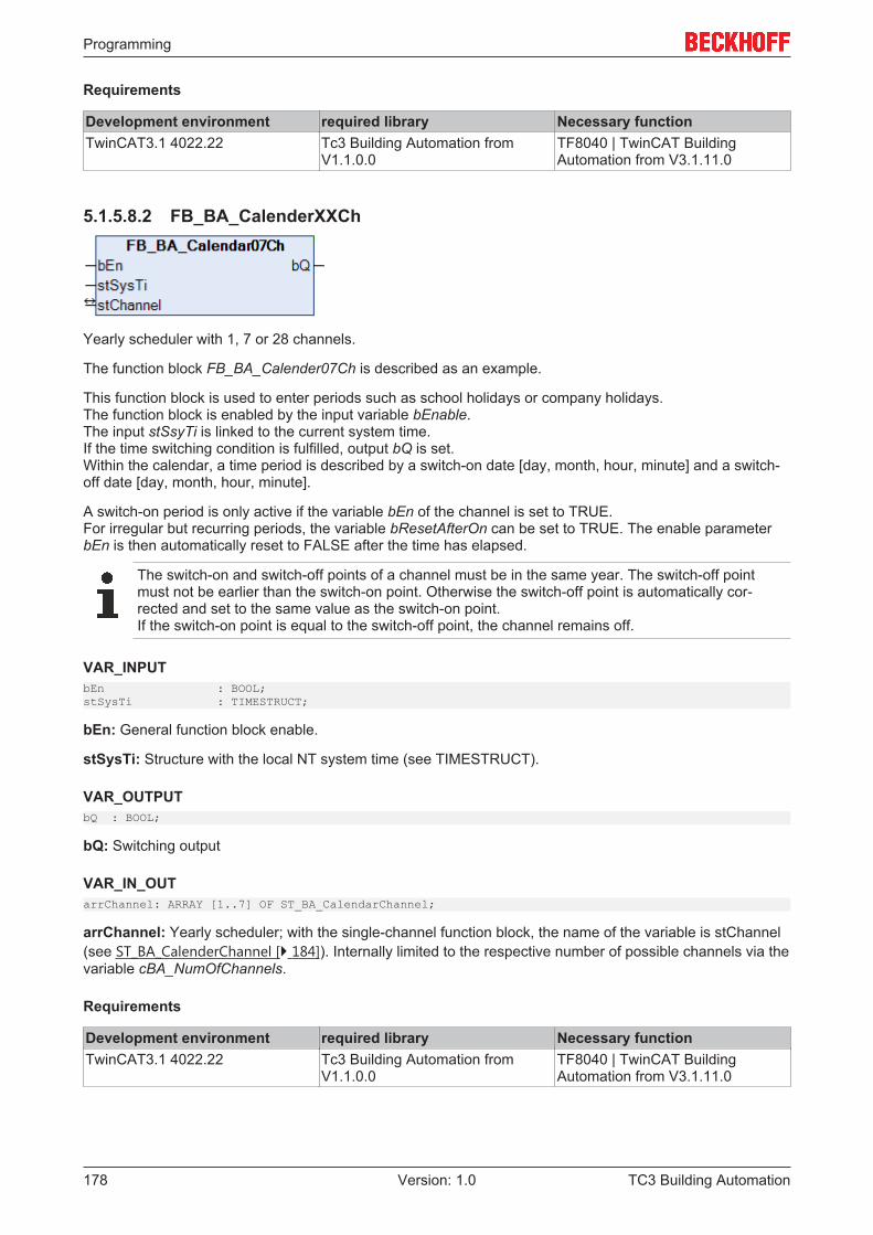
Programming
TC3 Building Automation178 Version: 1.0
Requirements
Development environment required library Necessary functionTwinCAT3.1 4022.22 Tc3 Building Automation from
V1.1.0.0TF8040 | TwinCAT BuildingAutomation from V3.1.11.0
5.1.5.8.2 FB_BA_CalenderXXCh
Yearly scheduler with 1, 7 or 28 channels.
The function block FB_BA_Calender07Ch is described as an example.
This function block is used to enter periods such as school holidays or company holidays.The function block is enabled by the input variable bEnable.The input stSsyTi is linked to the current system time.If the time switching condition is fulfilled, output bQ is set.Within the calendar, a time period is described by a switch-on date [day, month, hour, minute] and a switch-off date [day, month, hour, minute].
A switch-on period is only active if the variable bEn of the channel is set to TRUE.For irregular but recurring periods, the variable bResetAfterOn can be set to TRUE. The enable parameterbEn is then automatically reset to FALSE after the time has elapsed.
The switch-on and switch-off points of a channel must be in the same year. The switch-off pointmust not be earlier than the switch-on point. Otherwise the switch-off point is automatically cor-rected and set to the same value as the switch-on point.If the switch-on point is equal to the switch-off point, the channel remains off.
VAR_INPUTbEn : BOOL;stSysTi : TIMESTRUCT;
bEn: General function block enable.
stSysTi: Structure with the local NT system time (see TIMESTRUCT).
VAR_OUTPUTbQ : BOOL;
bQ: Switching output
VAR_IN_OUTarrChannel: ARRAY [1..7] OF ST_BA_CalendarChannel;
arrChannel: Yearly scheduler; with the single-channel function block, the name of the variable is stChannel(see ST_BA_CalenderChannel [} 184]). Internally limited to the respective number of possible channels via thevariable cBA_NumOfChannels.
Requirements
Development environment required library Necessary functionTwinCAT3.1 4022.22 Tc3 Building Automation from
V1.1.0.0TF8040 | TwinCAT BuildingAutomation from V3.1.11.0
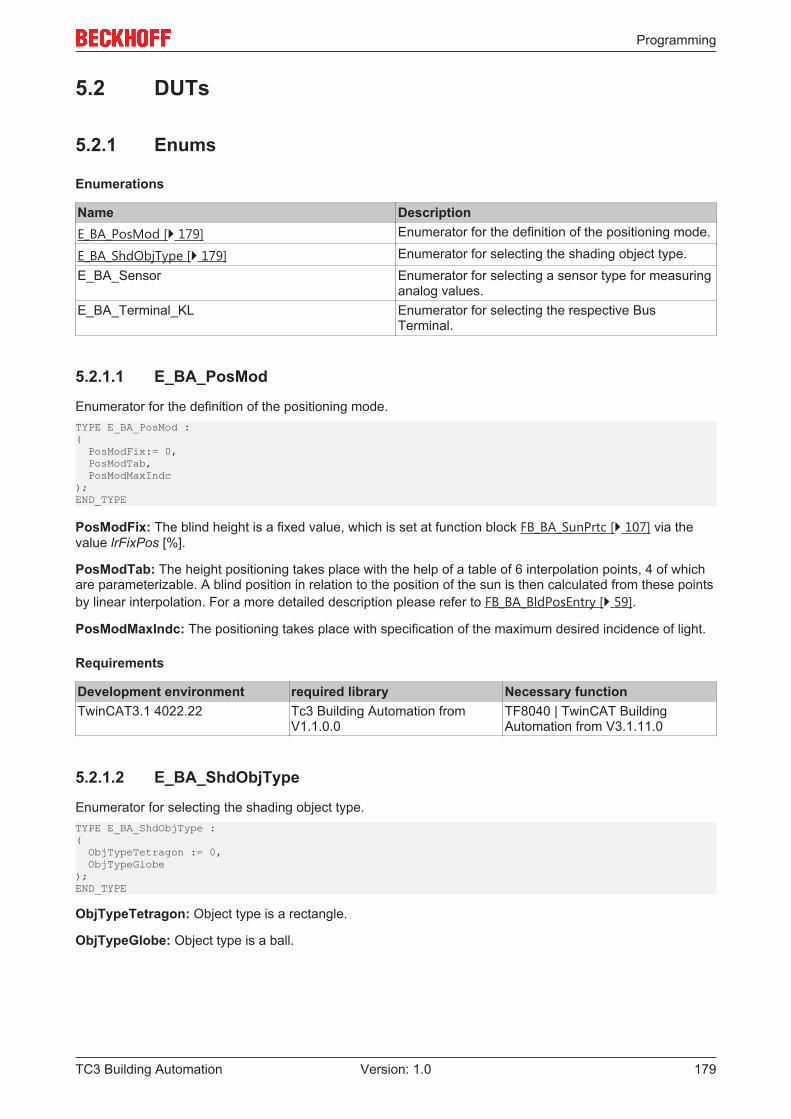
Programming
TC3 Building Automation 179Version: 1.0
5.2 DUTs
5.2.1 Enums
Enumerations
Name DescriptionE_BA_PosMod [} 179] Enumerator for the definition of the positioning mode.
E_BA_ShdObjType [} 179] Enumerator for selecting the shading object type.E_BA_Sensor Enumerator for selecting a sensor type for measuring
analog values.E_BA_Terminal_KL Enumerator for selecting the respective Bus
Terminal.
5.2.1.1 E_BA_PosMod
Enumerator for the definition of the positioning mode.TYPE E_BA_PosMod :( PosModFix:= 0, PosModTab, PosModMaxIndc);END_TYPE
PosModFix: The blind height is a fixed value, which is set at function block FB_BA_SunPrtc [} 107] via thevalue lrFixPos [%].
PosModTab: The height positioning takes place with the help of a table of 6 interpolation points, 4 of whichare parameterizable. A blind position in relation to the position of the sun is then calculated from these pointsby linear interpolation. For a more detailed description please refer to FB_BA_BldPosEntry [} 59].
PosModMaxIndc: The positioning takes place with specification of the maximum desired incidence of light.
Requirements
Development environment required library Necessary functionTwinCAT3.1 4022.22 Tc3 Building Automation from
V1.1.0.0TF8040 | TwinCAT BuildingAutomation from V3.1.11.0
5.2.1.2 E_BA_ShdObjType
Enumerator for selecting the shading object type.TYPE E_BA_ShdObjType :( ObjTypeTetragon := 0, ObjTypeGlobe);END_TYPE
ObjTypeTetragon: Object type is a rectangle.
ObjTypeGlobe: Object type is a ball.
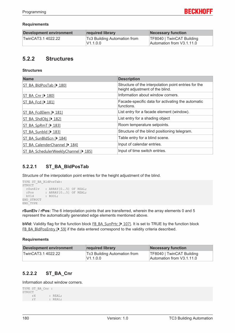
Programming
TC3 Building Automation180 Version: 1.0
Requirements
Development environment required library Necessary functionTwinCAT3.1 4022.22 Tc3 Building Automation from
V1.1.0.0TF8040 | TwinCAT BuildingAutomation from V3.1.11.0
5.2.2 Structures
Structures
Name DescriptionST_BA_BldPosTab [} 180] Structure of the interpolation point entries for the
height adjustment of the blind.ST_BA_Cnr [} 180] Information about window corners.
ST_BA_Fcd [} 181] Facade-specific data for activating the automaticfunctions.
ST_BA_FcdElem [} 181] List entry for a facade element (window).
ST_BA_ShdObj [} 182] List entry for a shading object
ST_BA_SpRmT [} 183] Room temperature setpoints.
ST_BA_Sunbld [} 183] Structure of the blind positioning telegram.
ST_BA_SunBldScn [} 184] Table entry for a blind scene.
ST_BA_CalenderChannel [} 184] Input of calendar entries.
ST_BA_SchedulerWeeklyChannel [} 185] Input of time switch entries.
5.2.2.1 ST_BA_BldPosTab
Structure of the interpolation point entries for the height adjustment of the blind.TYPE ST_BA_BldPosTab:STRUCT rSunElv : ARRAY[0..5] OF REAL; rPos : ARRAY[0..5] OF REAL; bVld : BOOL;END_STRUCTEND_TYPE
rSunElv / rPos: The 6 interpolation points that are transferred, wherein the array elements 0 and 5represent the automatically generated edge elements mentioned above.
bVld: Validity flag for the function block FB_BA_SunPrtc [} 107]. It is set to TRUE by the function blockFB_BA_BldPosEntry [} 59] if the data entered correspond to the validity criteria described.
Requirements
Development environment required library Necessary functionTwinCAT3.1 4022.22 Tc3 Building Automation from
V1.1.0.0TF8040 | TwinCAT BuildingAutomation from V3.1.11.0
5.2.2.2 ST_BA_Cnr
Information about window corners.TYPE ST_BA_Cnr :STRUCT rX : REAL; rY : REAL;
Programming
TC3 Building Automation 181Version: 1.0
bShdd : BOOL;END_STRUCTEND_TYPE
rX: X-coordinate of the window (on the facade).
rY: Y-coordinate of the window (on the facade).
bShdd: Information as to whether this corner is in the shade: bShdd=TRUE: Corner is in the shade.
Requirements
Development environment required library Necessary functionTwinCAT3.1 4022.22 Tc3 Building Automation from
V1.1.0.0TF8040 | TwinCAT BuildingAutomation from V3.1.11.0
5.2.2.3 ST_BA_Fcd
Facade-specific data at room level for activating the automatic functions.TYPE ST_BA_Fcd:STRUCT rSunPrtcAngl : REAL; rSunPrtcPos : REAL; rFcdThAutoPos : REAL; rFcdThAutoAngl : REAL; bFcdThAutoEn : BOOL; bThAutoEn : BOOL; bTwiLgtAutoEn : BOOL; bSunPrtcEn : BOOL;END_STRUCTEND_TYPE
rSunPrtcAngl: Sun protection: Current calculated position [%] for the blinds.
rSunPrtcPos: Sun protection: Current calculated louvre angle [°] for the blinds.
rFcdThAutoPos: Thermo-automatic function for whole facade: Currently valid position [%] for the blinds(heating or cooling position).
rFcdThAutoAngl: Thermo-automatic function for whole facade: Currently valid louvre angle [°] for the blinds(heating or cooling position).
bFcdThAutoEn: Thermo-automatic function for whole facade enabled.
bThAutoEn: Thermo-automatic function enabled.
bTwiLgtAutoEn: Automatic twilight function enabled.
bSunPrtcEn: Automatic sun protection enabled.
Requirements
Development environment required library Necessary functionTwinCAT3.1 4022.22 Tc3 Building Automation from
V1.1.0.0TF8040 | TwinCAT BuildingAutomation from V3.1.11.0
5.2.2.4 ST_BA_FcdElem
List entry for a facade element (window).TYPE ST_BA_FcdElem:STRUCT rWdwWdth : REAL; rWdwHght : REAL; stCnr : ARRAY [1..4] OF ST_BA_Cnr; diGrp : DINT;
Programming
TC3 Building Automation182 Version: 1.0
bVld : BOOL;END_STRUCTEND_TYPE
rWdwWdth: Width of the window.
rWdwHght: Height of the window.
stCnr: Coordinates of the window corners and information as to whether this corner point is in the shade;see ST_BA_Cnr [} 180].
bVld: Plausibility of the data entered: bVld=TRUE: Data are plausible.
diGrp: Group membership of the element.
Requirements
Development environment required library Necessary functionTwinCAT3.1 4022.22 Tc3 Building Automation from
V1.1.0.0TF8040 | TwinCAT BuildingAutomation from V3.1.11.0
5.2.2.5 ST_BA_ShdObj
List entry for a shading object.TYPE ST_BA_ShdObj :STRUCT rP1x : REAL; rP1y : REAL; rP1z : REAL; rP2x : REAL; rP2y : REAL; rP2z : REAL; rP3x : REAL; rP3y : REAL; rP3z : REAL; rP4x : REAL; rP4y : REAL; rP4z : REAL; rMx : REAL; rMy : REAL; rMz : REAL; rRads : REAL; diBegMth : USINT; diEndMth : USINT; eType : E_BA_ShdObjType; bVld : BOOL;END_STRUCTEND_TYPE
rP1x .. rP4z: Corner coordinates. Of importance only if the element is a square.
rMx .. rMz: Center coordinates. Of importance only if the element is a ball.
rRads: Radius of the ball. Of importance only if the element is a ball.
diBegMth: Beginning of the shading period (month).
diEndMth: End of the shading period (month).
eType: Object type, see E_BA_ShdObjType [} 179].
bVld: Plausibility of the data: bVld=TRUE: Data are plausible.
Remark about the shading period:
The entries for the months may not be 0 or greater than 12, otherwise all combinations are possible.
Programming
TC3 Building Automation 183Version: 1.0
Examples:
Start=1, End=1: shading in January.Start=1, End=5: shading from the beginning of January to the end of May.Start=11, End=5: shading from the beginning of November to the end of May (the following year).
Requirements
Development environment required library Necessary functionTwinCAT3.1 4022.22 Tc3 Building Automation from
V1.1.0.0TF8040 | TwinCAT BuildingAutomation from V3.1.11.0
5.2.2.6 ST_BA_SpRmT
Room temperature setpoints.TYPE ST_BA_SpRmT :STRUCT rPrtcHtg : REAL := 12.0; rEcoHtg : REAL := 15.0; rPreCmfHtg : REAL := 19.0; rCmfHtg : REAL := 21.0; rPrtcCol : REAL := 40.0; rEcoCol : REAL := 35.0; rPreCmfCol : REAL := 28.0; rCmfCol : REAL := 24.0;END_STRUCTEND_TYPE
The values in the structure are defined with the preset values.
The variables have the following meaning:
rPrtcHtg: Protection Heating.
rEcoHtg: Economy Heating.
rPreCmfHtg: Pre-Comfort Heating.
rCmfHtg: Comfort Heating.
rPrtcCol: Protection Cooling.
rEcoCol: Economy Cooling.
rPreCmfCol: Pre-Comfort Cooling.
rCmfCol: Comfort Cooling.
Requirements
Development environment required library Necessary functionTwinCAT3.1 4022.22 Tc3 Building Automation from
V1.1.0.0TF8040 | TwinCAT BuildingAutomation from V3.1.11.0
5.2.2.7 ST_BA_Sunbld
Structure of the blind positioning telegram.TYPE ST_BA_SunBld:STRUCT rPos : REAL; rAngl : REAL; bManUp : BOOL; bManDwn : BOOL; bManMod : BOOL;
Programming
TC3 Building Automation184 Version: 1.0
bActv : BOOL;END_STRUCTEND_TYPE
rPos: Transferred blind height [%].
rAngl: Transferred louvre position [°].
bManUp: Manual command: blind up.
bManDwn: Manual command: blind down.
bManMod: TRUE: Manual mode is active. FALSE: Automatic mode is active.
bActv: The sender of the telegram is active. This bit is only evaluated by the priority controlFB_BA_SunBldPrioSwi4 [} 97] or FB_BA_SunBldPrioSwi8 [} 98]. The sun protection actuatorsFB_BA_SunBldActr [} 89] and FB_BA_RolBldActr [} 81] ignore it.
Requirements
Development environment required library Necessary functionTwinCAT3.1 4022.22 Tc3 Building Automation from
V1.1.0.0TF8040 | TwinCAT BuildingAutomation from V3.1.11.0
5.2.2.8 ST_BA_SunBldScn
Table entry for a blind scene.TYPE ST_BA_SunBldScn:STRUCT rPos : REAL; rAngl : REAL;END_STRUCTEND_TYPE
rPos: Blind height [%].
rAngl: Louvre position [°].
Requirements
Development environment required library Necessary functionTwinCAT3.1 4022.22 Tc3 Building Automation from
V1.1.0.0TF8040 | TwinCAT BuildingAutomation from V3.1.11.0
5.2.2.9 ST_BA_CalenderChannel
Structure for entering calendar entries.TYPE ST_BA_CalendarChannel:STRUCT udiOn_Day : UDINT(1..31); udiOn_Month : UDINT(1..12); udiOn_hh : UDINT(0..23); udiOn_mm : UDINT(0..59); udiOff_Day : UDINT(1..31); udiOff_Month : UDINT(1..12); udiOff_hh : UDINT(0..23); udiOff_mm : UDINT(0..59); bEn : BOOL; bResetAfterOn : BOOL; bQ : BOOL;END_STRUCTEND_TYPE
udiOn_Day: Switch-on point for day.
udiOn_Month: Switch-on point for month.
Programming
TC3 Building Automation 185Version: 1.0
udiOn_hh: Switch-on point for hour.
udiOn_mm: Switch-on point for minute.
udiOff_Day: Switch-off point for day.
udiOff_Month: Switch-off point for month.
udiOff_hh: Switch-off point for hour.
udiOff_mm: Switch-off point for minute.
bEn: TRUE -> Enable channel, FALSE -> bQ = FALSE
bResetAfterOn: One-time and non-recurring switching-on.
bQ: Channel status output.
Requirements
Development environment required library Necessary functionTwinCAT3.1 4022.22 Tc3 Building Automation from
V1.1.0.0TF8040 | TwinCAT BuildingAutomation from V3.1.11.0
5.2.2.10 ST_BA_SchedulerWeeklyChannel
Structure for entering time switch entries.TYPE ST_BA_SchedulerWeeklyChannel:STRUCT udiOn_hh : UDINT(0..23); udiOn_mm : UDINT(0..59); udiOn_ss : UDINT(0..59); udiOff_hh : UDINT(0..23); udiOff_mm : UDINT(0..59); udiOff_ss : UDINT(0..59); bAllActive : BOOL; bEn : BOOL; bMonday : BOOL; bTuesday : BOOL; bWednesday : BOOL; bThursday : BOOL; bFriday : BOOL; bSaturday : BOOL; bSunday : BOOL; bResetAfterOn : BOOL; bQ : BOOL;END_STRUCTEND_TYPE
udiOn_hh: Switch-on point for hour.
udiOn_mm: Switch-on point for minute.
udiOn_ss: Switch-on point for second.
udiOff_hh: Switch-off point for hour.
udiOff_mm: Switch-off point for minute.
udiOff_ss: Switch-off point for second.
bAllActive: Activation of the timer condition for all weekdays.
bEn: TRUE -> Enable channel, FALSE -> bQ = FALSE.
bMonday: Switch-on point for Monday.
bTuesday: Switch-on point for Tuesday.
bWednesday: Switch-on point for Wednesday.
Programming
TC3 Building Automation186 Version: 1.0
bThursday: Switch-on point for Thursday.
bFriday: Switch on point for Friday.
bSaturday: Switch-on point for Saturday.
bSunday: Switch-on point for Sunday.
bResetAfterOn: One-time and non-recurring switching-on.
bQ: Channel status output.
Requirements
Development environment required library Necessary functionTwinCAT3.1 4022.22 Tc3 Building Automation from
V1.1.0.0TF8040 | TwinCAT BuildingAutomation from V3.1.11.0
5.3 GVLs
5.3.1 ConstantsGlobal constantsVAR_GLOBAL CONSTANT rClsZero : REAL := 0.00001;
udiNoActvPrio : UDINT := 4294967295;
udiTiSec : UDINT := 4294967295;
wSUNDAY : WORD := 0; wMONDAY : WORD := 1; wTUESDAY : WORD := 2; wWEDNESDAY : WORD := 3; wTHURSDAY : WORD := 4; wFRIDAY : WORD := 5; wSATURDAY : WORD := 6;
TimeValue24h_ms : UDINT := 86400000;END_VAR
rClsZero: Reference value to avoid division by zero.
udiNoActvPrio: The value of the constants indicates that no priority is active.
udiTiSec: Constant for specifying a time in seconds.
wSUNDAY: Constant value for Sunday.
wMONDAY: Constant value for Monday.
wTUESDAY: Constant value for Tuesday.
wWEDNESDAY: Constant value for Wednesday.
wTHURSDAY: Constant value for Thursday.
wFRIDAY: Constant value for Friday.
wSATURDAY: Constant value for Saturday.
TimeValue24h_ms: Time value for 24 hours in milliseconds.
Programming
TC3 Building Automation 187Version: 1.0
Requirements
Development environment required library Necessary functionTwinCAT3.1 4022.22 Tc3 Building Automation from
V1.1.0.0TF8040 | TwinCAT BuildingAutomation from V3.1.11.0
5.3.2 ParameterGlobal parametersVAR_GLOBAL CONSTANT usiMaxSunBldScn : USINT := 20; uiMaxRowFcd : UINT := 10; uiMaxColumnFcd : UINT := 20; uiMaxShdObj : UINT := 20; udiMaxDataFileSize : UDINT := 100000;END_VAR
usiMaxSunBldScn: Maximum number of scenes that are processed by the function block FB_BA_SunBldScn[} 99].
uiMaxRowFcd: Maximum number of floors for which the shading correction applies (horizontal arrangementof windows).
uiMaxColumnFcd: Maximum number of axes for which the shading correction applies (vertical arrangementof windows).
uiMaxShdObj: Maximum number of shading objects that cast shadows on the facade.
udiMaxDataFileSize: Maximum file size for the Excel list (in bytes), which is read by the function blocksFB_BA_RdFcdElemLst [} 73] and FB_BA_RdShdObjLst [} 77].
Requirements
Development environment required library Necessary functionTwinCAT3.1 4022.22 Tc3 Building Automation from
V1.1.0.0TF8040 | TwinCAT BuildingAutomation from V3.1.11.0
Appendix
TC3 Building Automation188 Version: 1.0
6 Appendix
6.1 Support and ServiceBeckhoff and their partners around the world offer comprehensive support and service, making available fastand competent assistance with all questions related to Beckhoff products and system solutions.
Beckhoff's branch offices and representatives
Please contact your Beckhoff branch office or representative for local support and service on Beckhoffproducts!
The addresses of Beckhoff's branch offices and representatives round the world can be found on her internetpages:http://www.beckhoff.com
You will also find further documentation for Beckhoff components there.
Beckhoff Headquarters
Beckhoff Automation GmbH & Co. KG
Huelshorstweg 2033415 VerlGermany
Phone: +49(0)5246/963-0Fax: +49(0)5246/963-198e-mail: [email protected]
Beckhoff Support
Support offers you comprehensive technical assistance, helping you not only with the application ofindividual Beckhoff products, but also with other, wide-ranging services:
• support• design, programming and commissioning of complex automation systems• and extensive training program for Beckhoff system components
Hotline: +49(0)5246/963-157Fax: +49(0)5246/963-9157e-mail: [email protected]
Beckhoff Service
The Beckhoff Service Center supports you in all matters of after-sales service:
• on-site service• repair service• spare parts service• hotline service
Hotline: +49(0)5246/963-460Fax: +49(0)5246/963-479e-mail: [email protected]