
Manual TC3 IoT Functions - Beckhoff Automation · TC3 IoT Functions and TC3 IoT Data Agent on a...
41
Manual TC3 IoT Functions TwinCAT 3 1.0 2018-05-25 TF6710 Version: Date: Order No.:
Transcript of Manual TC3 IoT Functions - Beckhoff Automation · TC3 IoT Functions and TC3 IoT Data Agent on a...
Manual
TC3 IoT Functions
TwinCAT 3
1.02018-05-25TF6710
Version:Date:Order No.:

Table of contents
TC3 IoT Functions 3Version: 1.0
Table of contents1 Foreword .................................................................................................................................................... 5
1.1 Notes on the documentation........................................................................................................... 51.2 Safety instructions .......................................................................................................................... 6
2 Overview..................................................................................................................................................... 7
3 Installation.................................................................................................................................................. 83.1 System requirements...................................................................................................................... 83.2 Setup scenarios .............................................................................................................................. 83.3 Installation....................................................................................................................................... 83.4 Licensing....................................................................................................................................... 11
4 Technical introduction ............................................................................................................................ 164.1 Reference Data Agent .................................................................................................................. 174.2 Communication patterns............................................................................................................... 174.3 Programming workflow ................................................................................................................. 184.4 Synchronizing message operations.............................................................................................. 194.5 Timeout settings ........................................................................................................................... 21
5 Configuration ........................................................................................................................................... 235.1 Overview....................................................................................................................................... 235.2 Configurator .................................................................................................................................. 23
5.2.1 Topology view .................................................................................................................. 255.2.2 Tree view.......................................................................................................................... 265.2.3 Mappings.......................................................................................................................... 275.2.4 Target Browser................................................................................................................. 275.2.5 Cascading Editor.............................................................................................................. 275.2.6 Settings ............................................................................................................................ 285.2.7 Error logging..................................................................................................................... 33
6 PLC API .................................................................................................................................................... 356.1 Function blocks............................................................................................................................. 35
6.1.1 FB_IotFunctions_Connector ............................................................................................ 356.1.2 FB_IotFunctions_Message .............................................................................................. 366.1.3 FB_IotFunctions_Request ............................................................................................... 37
6.2 Data types..................................................................................................................................... 386.2.1 ST_IotFunctionsEvent...................................................................................................... 386.2.2 ST_IotFunctionsMessage ................................................................................................ 386.2.3 ST_IotFunctionsRequest ................................................................................................. 396.2.4 ST_IotFunctionsRequestContainer .................................................................................. 39
7 Samples.................................................................................................................................................... 40
8 Appendix .................................................................................................................................................. 418.1 Support and Service ..................................................................................................................... 41

Table of contents
TC3 IoT Functions4 Version: 1.0
Foreword
TC3 IoT Functions 5Version: 1.0
1 Foreword
1.1 Notes on the documentationThis description is only intended for the use of trained specialists in control and automation engineering whoare familiar with the applicable national standards.It is essential that the documentation and the following notes and explanations are followed when installingand commissioning the components. It is the duty of the technical personnel to use the documentation published at the respective time of eachinstallation and commissioning.
The responsible staff must ensure that the application or use of the products described satisfy all therequirements for safety, including all the relevant laws, regulations, guidelines and standards.
Disclaimer
The documentation has been prepared with care. The products described are, however, constantly underdevelopment.We reserve the right to revise and change the documentation at any time and without prior announcement.No claims for the modification of products that have already been supplied may be made on the basis of thedata, diagrams and descriptions in this documentation.
Trademarks
Beckhoff®, TwinCAT®, EtherCAT®, Safety over EtherCAT®, TwinSAFE®, XFC® and XTS® are registeredtrademarks of and licensed by Beckhoff Automation GmbH.Other designations used in this publication may be trademarks whose use by third parties for their ownpurposes could violate the rights of the owners.
Patent Pending
The EtherCAT Technology is covered, including but not limited to the following patent applications andpatents:EP1590927, EP1789857, DE102004044764, DE102007017835with corresponding applications or registrations in various other countries.
The TwinCAT Technology is covered, including but not limited to the following patent applications andpatents:EP0851348, US6167425 with corresponding applications or registrations in various other countries.
EtherCAT® is registered trademark and patented technology, licensed by Beckhoff Automation GmbH,Germany
Copyright
© Beckhoff Automation GmbH & Co. KG, Germany.The reproduction, distribution and utilization of this document as well as the communication of its contents toothers without express authorization are prohibited.Offenders will be held liable for the payment of damages. All rights reserved in the event of the grant of apatent, utility model or design.
Foreword
TC3 IoT Functions6 Version: 1.0
1.2 Safety instructions
Safety regulations
Please note the following safety instructions and explanations!Product-specific safety instructions can be found on following pages or in the areas mounting, wiring,commissioning etc.
Exclusion of liability
All the components are supplied in particular hardware and software configurations appropriate for theapplication. Modifications to hardware or software configurations other than those described in thedocumentation are not permitted, and nullify the liability of Beckhoff Automation GmbH & Co. KG.
Personnel qualification
This description is only intended for trained specialists in control, automation and drive engineering who arefamiliar with the applicable national standards.
Description of symbols
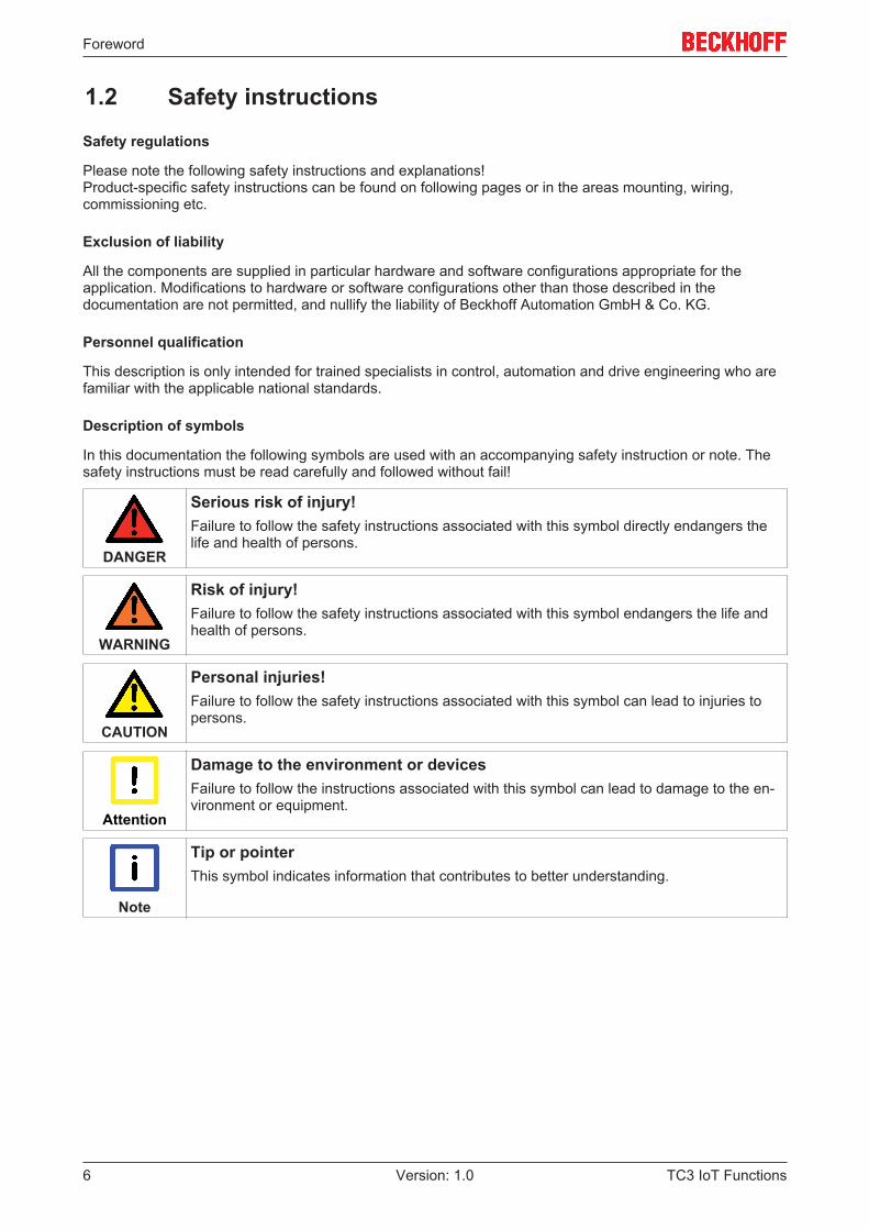
In this documentation the following symbols are used with an accompanying safety instruction or note. Thesafety instructions must be read carefully and followed without fail!
DANGER
Serious risk of injury!Failure to follow the safety instructions associated with this symbol directly endangers thelife and health of persons.
WARNING
Risk of injury!Failure to follow the safety instructions associated with this symbol endangers the life andhealth of persons.
CAUTION
Personal injuries!Failure to follow the safety instructions associated with this symbol can lead to injuries topersons.
Attention
Damage to the environment or devicesFailure to follow the instructions associated with this symbol can lead to damage to the en-vironment or equipment.
Note
Tip or pointerThis symbol indicates information that contributes to better understanding.
Overview
TC3 IoT Functions 7Version: 1.0
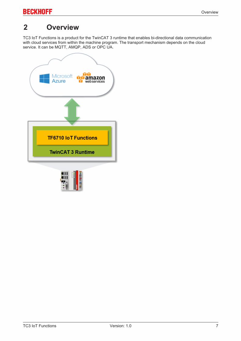
2 OverviewTC3 IoT Functions is a product for the TwinCAT 3 runtime that enables bi-directional data communicationwith cloud services from within the machine program. The transport mechanism depends on the cloudservice. It can be MQTT, AMQP, ADS or OPC UA.
Installation
TC3 IoT Functions8 Version: 1.0
3 Installation
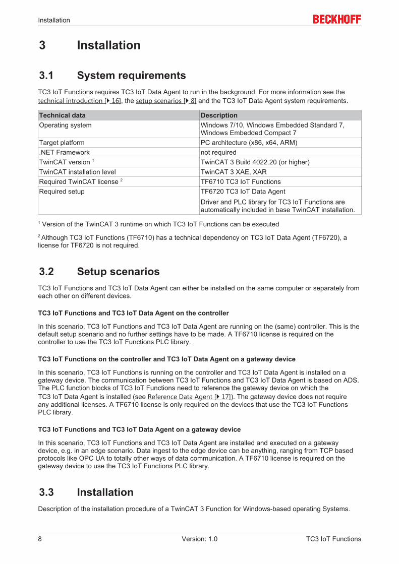
3.1 System requirementsTC3 IoT Functions requires TC3 IoT Data Agent to run in the background. For more information see thetechnical introduction [} 16], the setup scenarios [} 8] and the TC3 IoT Data Agent system requirements.
Technical data DescriptionOperating system Windows 7/10, Windows Embedded Standard 7,
Windows Embedded Compact 7Target platform PC architecture (x86, x64, ARM).NET Framework not requiredTwinCAT version 1 TwinCAT 3 Build 4022.20 (or higher)TwinCAT installation level TwinCAT 3 XAE, XARRequired TwinCAT license 2 TF6710 TC3 IoT FunctionsRequired setup TF6720 TC3 IoT Data Agent
Driver and PLC library for TC3 IoT Functions areautomatically included in base TwinCAT installation.
1 Version of the TwinCAT 3 runtime on which TC3 IoT Functions can be executed2 Although TC3 IoT Functions (TF6710) has a technical dependency on TC3 IoT Data Agent (TF6720), alicense for TF6720 is not required.
3.2 Setup scenariosTC3 IoT Functions and TC3 IoT Data Agent can either be installed on the same computer or separately fromeach other on different devices.
TC3 IoT Functions and TC3 IoT Data Agent on the controller
In this scenario, TC3 IoT Functions and TC3 IoT Data Agent are running on the (same) controller. This is thedefault setup scenario and no further settings have to be made. A TF6710 license is required on thecontroller to use the TC3 IoT Functions PLC library.
TC3 IoT Functions on the controller and TC3 IoT Data Agent on a gateway device
In this scenario, TC3 IoT Functions is running on the controller and TC3 IoT Data Agent is installed on agateway device. The communication between TC3 IoT Functions and TC3 IoT Data Agent is based on ADS.The PLC function blocks of TC3 IoT Functions need to reference the gateway device on which theTC3 IoT Data Agent is installed (see Reference Data Agent [} 17]). The gateway device does not requireany additional licenses. A TF6710 license is only required on the devices that use the TC3 IoT FunctionsPLC library.
TC3 IoT Functions and TC3 IoT Data Agent on a gateway device
In this scenario, TC3 IoT Functions and TC3 IoT Data Agent are installed and executed on a gatewaydevice, e.g. in an edge scenario. Data ingest to the edge device can be anything, ranging from TCP basedprotocols like OPC UA to totally other ways of data communication. A TF6710 license is required on thegateway device to use the TC3 IoT Functions PLC library.
3.3 InstallationDescription of the installation procedure of a TwinCAT 3 Function for Windows-based operating Systems.
Installation
TC3 IoT Functions 9Version: 1.0
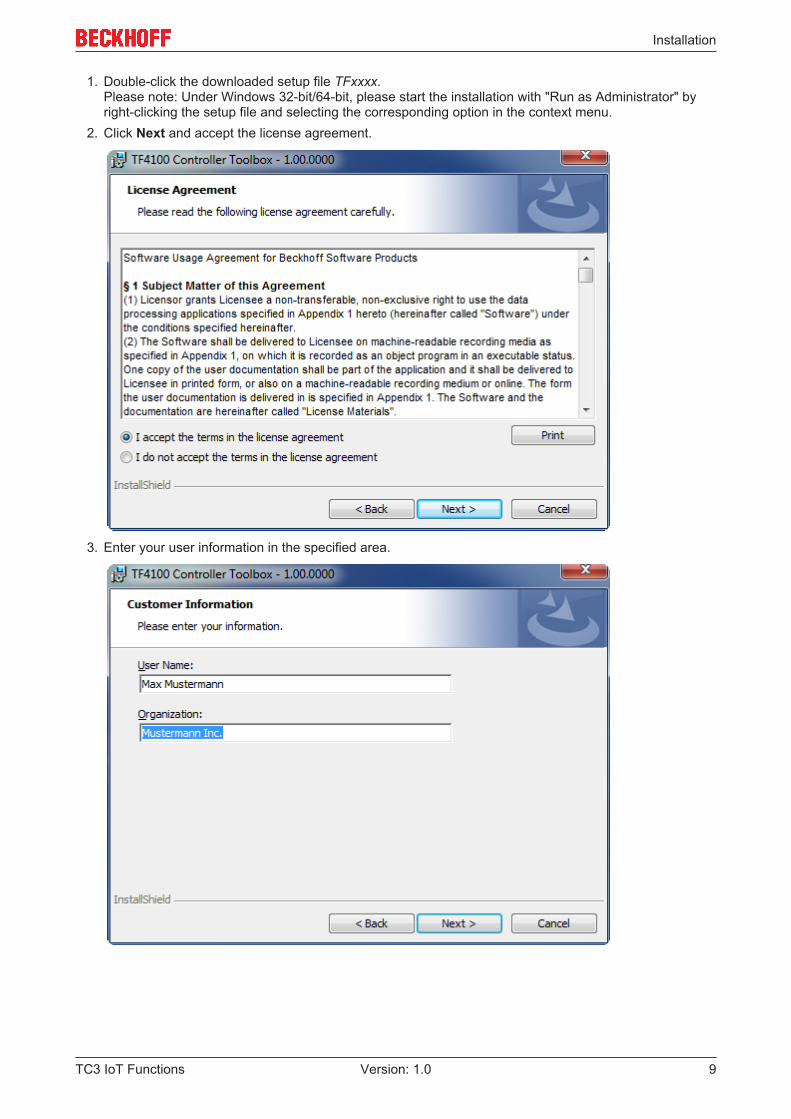
1. Double-click the downloaded setup file TFxxxx.Please note: Under Windows 32-bit/64-bit, please start the installation with "Run as Administrator" byright-clicking the setup file and selecting the corresponding option in the context menu.
2. Click Next and accept the license agreement.
3. Enter your user information in the specified area.
Installation
TC3 IoT Functions10 Version: 1.0
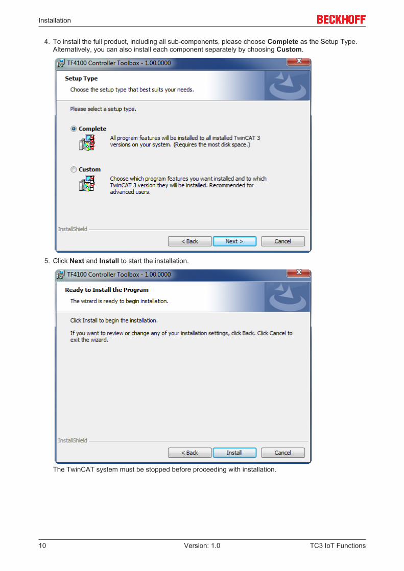
4. To install the full product, including all sub-components, please choose Complete as the Setup Type.Alternatively, you can also install each component separately by choosing Custom.
5. Click Next and Install to start the installation.
The TwinCAT system must be stopped before proceeding with installation.
Installation
TC3 IoT Functions 11Version: 1.0
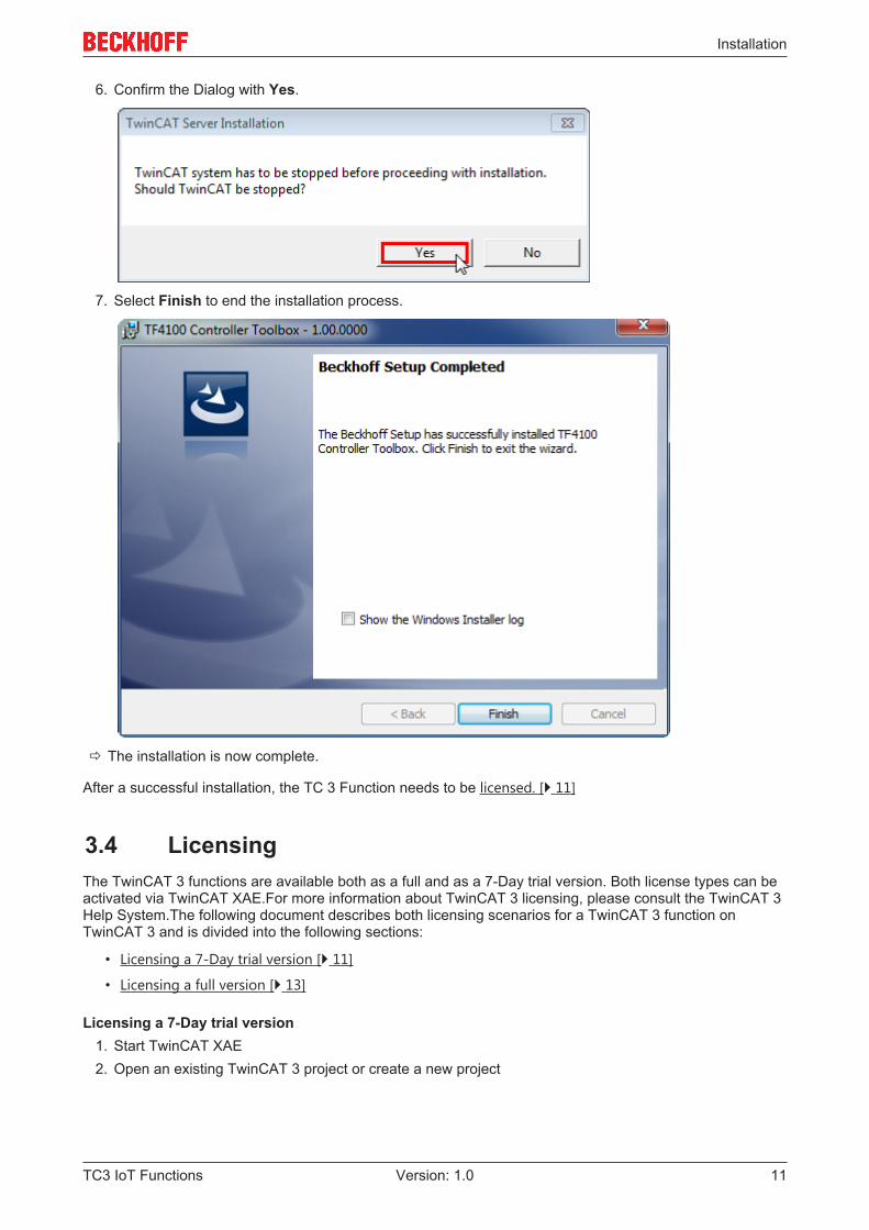
6. Confirm the Dialog with Yes.
7. Select Finish to end the installation process.
ð The installation is now complete.
After a successful installation, the TC 3 Function needs to be licensed. [} 11]
3.4 LicensingThe TwinCAT 3 functions are available both as a full and as a 7-Day trial version. Both license types can beactivated via TwinCAT XAE.For more information about TwinCAT 3 licensing, please consult the TwinCAT 3Help System.The following document describes both licensing scenarios for a TwinCAT 3 function onTwinCAT 3 and is divided into the following sections:
• Licensing a 7-Day trial version [} 11]
• Licensing a full version [} 13]
Licensing a 7-Day trial version1. Start TwinCAT XAE2. Open an existing TwinCAT 3 project or create a new project
Installation
TC3 IoT Functions12 Version: 1.0
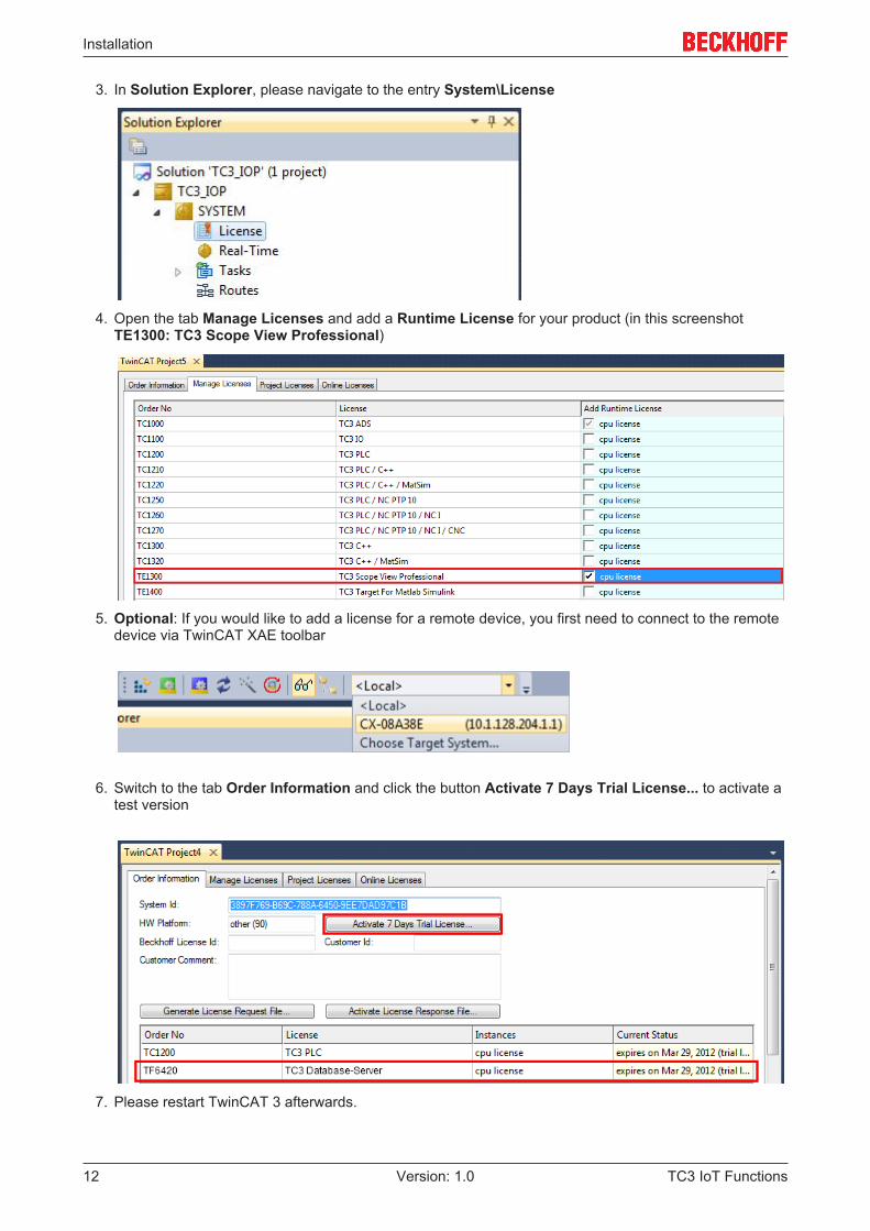
3. In Solution Explorer, please navigate to the entry System\License
4. Open the tab Manage Licenses and add a Runtime License for your product (in this screenshotTE1300: TC3 Scope View Professional)
5. Optional: If you would like to add a license for a remote device, you first need to connect to the remotedevice via TwinCAT XAE toolbar
6. Switch to the tab Order Information and click the button Activate 7 Days Trial License... to activate atest version
7. Please restart TwinCAT 3 afterwards.
Installation
TC3 IoT Functions 13Version: 1.0
Licensing a full version8. Start TwinCAT XAE9. Open an existing TwinCAT 3 project or create a new project
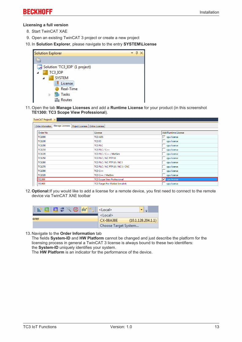
10. In Solution Explorer, please navigate to the entry SYSTEM\License
11. Open the tab Manage Licenses and add a Runtime License for your product (in this screenshotTE1300: TC3 Scope View Professional).
12. Optional:If you would like to add a license for a remote device, you first need to connect to the remotedevice via TwinCAT XAE toolbar
13. Navigate to the Order Information tabThe fields System-ID and HW Platform cannot be changed and just describe the platform for thelicensing process in general a TwinCAT 3 license is always bound to these two identifiers:the System-ID uniquely identifies your system.The HW Platform is an indicator for the performance of the device.
Installation
TC3 IoT Functions14 Version: 1.0
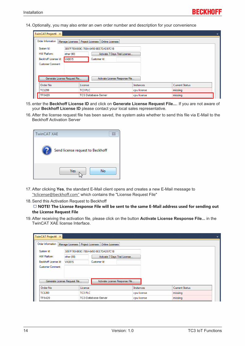
14. Optionally, you may also enter an own order number and description for your convenience
15. enter the Beckhoff License ID and click on Generate License Request File.... If you are not aware ofyour Beckhoff License ID please contact your local sales representative.
16. After the license request file has been saved, the system asks whether to send this file via E-Mail to theBeckhoff Activation Server
17. After clicking Yes, the standard E-Mail client opens and creates a new E-Mail message to"[email protected]" which contains the "License Request File"
18. Send this Activation Request to BeckhoffNOTE! The License Response File will be sent to the same E-Mail address used for sending out
the License Request File19. After receiving the activation file, please click on the button Activate License Response File... in the
TwinCAT XAE license Interface.
Installation
TC3 IoT Functions 15Version: 1.0
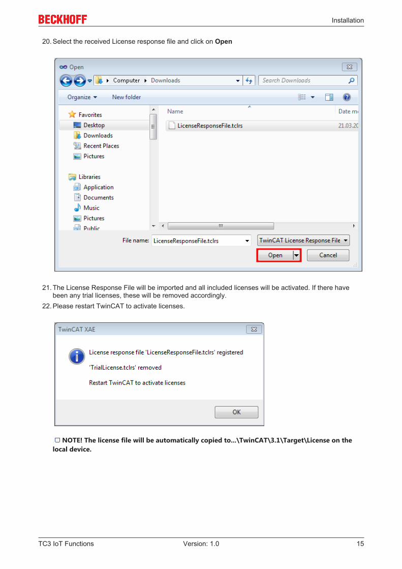
20. Select the received License response file and click on Open
21. The License Response File will be imported and all included licenses will be activated. If there havebeen any trial licenses, these will be removed accordingly.
22. Please restart TwinCAT to activate licenses.
NOTE! The license file will be automatically copied to...\TwinCAT\3.1\Target\License on thelocal device.
Technical introduction
TC3 IoT Functions16 Version: 1.0
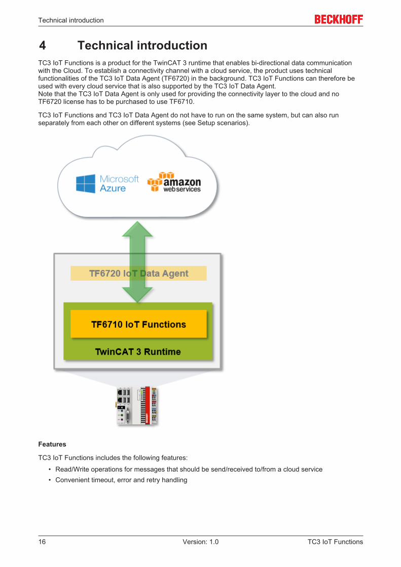
4 Technical introductionTC3 IoT Functions is a product for the TwinCAT 3 runtime that enables bi-directional data communicationwith the Cloud. To establish a connectivity channel with a cloud service, the product uses technicalfunctionalities of the TC3 IoT Data Agent (TF6720) in the background. TC3 IoT Functions can therefore beused with every cloud service that is also supported by the TC3 IoT Data Agent.Note that the TC3 IoT Data Agent is only used for providing the connectivity layer to the cloud and noTF6720 license has to be purchased to use TF6710.
TC3 IoT Functions and TC3 IoT Data Agent do not have to run on the same system, but can also runseparately from each other on different systems (see Setup scenarios).
Features
TC3 IoT Functions includes the following features:
• Read/Write operations for messages that should be send/received to/from a cloud service• Convenient timeout, error and retry handling
Technical introduction
TC3 IoT Functions 17Version: 1.0
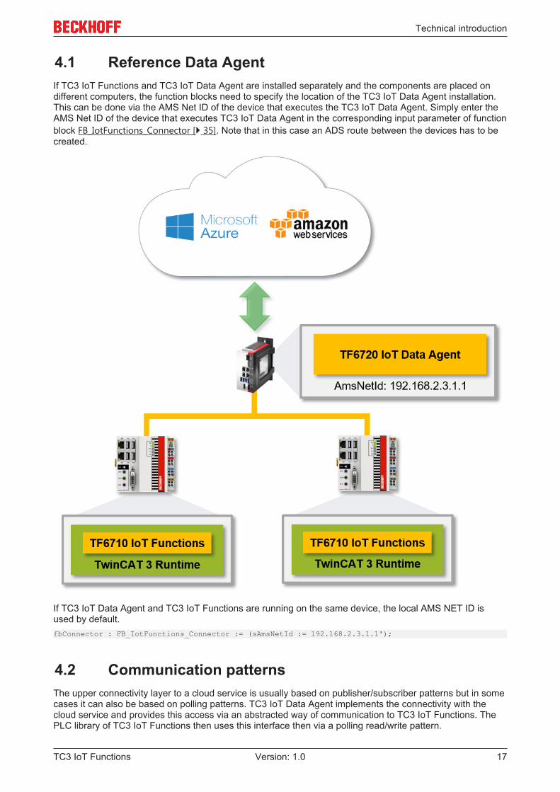
4.1 Reference Data AgentIf TC3 IoT Functions and TC3 IoT Data Agent are installed separately and the components are placed ondifferent computers, the function blocks need to specify the location of the TC3 IoT Data Agent installation.This can be done via the AMS Net ID of the device that executes the TC3 IoT Data Agent. Simply enter theAMS Net ID of the device that executes TC3 IoT Data Agent in the corresponding input parameter of functionblock FB_IotFunctions_Connector [} 35]. Note that in this case an ADS route between the devices has to becreated.
If TC3 IoT Data Agent and TC3 IoT Functions are running on the same device, the local AMS NET ID isused by default.fbConnector : FB_IotFunctions_Connector := (sAmsNetId := 192.168.2.3.1.1');
4.2 Communication patternsThe upper connectivity layer to a cloud service is usually based on publisher/subscriber patterns but in somecases it can also be based on polling patterns. TC3 IoT Data Agent implements the connectivity with thecloud service and provides this access via an abstracted way of communication to TC3 IoT Functions. ThePLC library of TC3 IoT Functions then uses this interface then via a polling read/write pattern.
Technical introduction
TC3 IoT Functions18 Version: 1.0
Example
TC3 IoT Functions should be used to read messages from Azure IoT Hub. Connectivity with this cloudservice is based on the publisher/subscriber pattern. This means that TC3 IoT Data Agent is configured withaccess credentials to the IoT Hub service and will therefore provides connectivity to it. TC3 IoT Functionsthen polls the TC3 IoT Data Agent for any incoming messages.
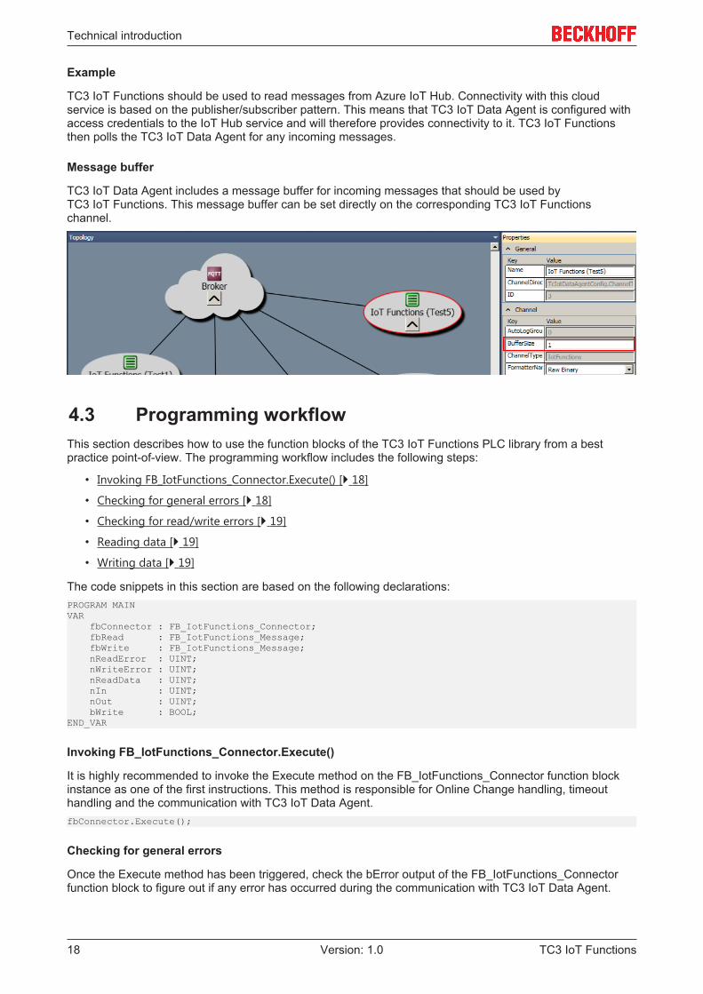
Message buffer
TC3 IoT Data Agent includes a message buffer for incoming messages that should be used byTC3 IoT Functions. This message buffer can be set directly on the corresponding TC3 IoT Functionschannel.
4.3 Programming workflowThis section describes how to use the function blocks of the TC3 IoT Functions PLC library from a bestpractice point-of-view. The programming workflow includes the following steps:
• Invoking FB_IotFunctions_Connector.Execute() [} 18]
• Checking for general errors [} 18]
• Checking for read/write errors [} 19]
• Reading data [} 19]
• Writing data [} 19]
The code snippets in this section are based on the following declarations:PROGRAM MAINVAR fbConnector : FB_IotFunctions_Connector; fbRead : FB_IotFunctions_Message; fbWrite : FB_IotFunctions_Message; nReadError : UINT; nWriteError : UINT; nReadData : UINT; nIn : UINT; nOut : UINT; bWrite : BOOL;END_VAR
Invoking FB_IotFunctions_Connector.Execute()
It is highly recommended to invoke the Execute method on the FB_IotFunctions_Connector function blockinstance as one of the first instructions. This method is responsible for Online Change handling, timeouthandling and the communication with TC3 IoT Data Agent.fbConnector.Execute();
Checking for general errors
Once the Execute method has been triggered, check the bError output of the FB_IotFunctions_Connectorfunction block to figure out if any error has occurred during the communication with TC3 IoT Data Agent.
Technical introduction
TC3 IoT Functions 19Version: 1.0
IF fbConnector.bError THEN ...END_IF
Checking for read/write errors
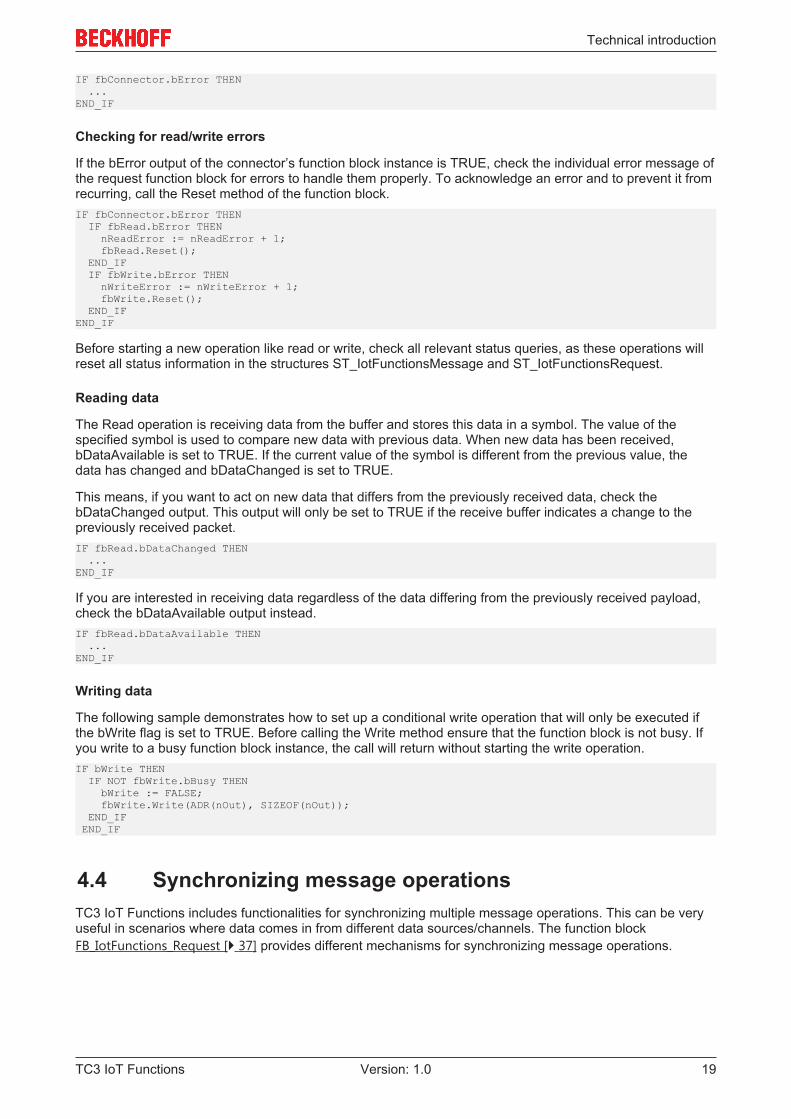
If the bError output of the connector’s function block instance is TRUE, check the individual error message ofthe request function block for errors to handle them properly. To acknowledge an error and to prevent it fromrecurring, call the Reset method of the function block.IF fbConnector.bError THEN IF fbRead.bError THEN nReadError := nReadError + 1; fbRead.Reset(); END_IF IF fbWrite.bError THEN nWriteError := nWriteError + 1; fbWrite.Reset(); END_IFEND_IF
Before starting a new operation like read or write, check all relevant status queries, as these operations willreset all status information in the structures ST_IotFunctionsMessage and ST_IotFunctionsRequest.
Reading data
The Read operation is receiving data from the buffer and stores this data in a symbol. The value of thespecified symbol is used to compare new data with previous data. When new data has been received,bDataAvailable is set to TRUE. If the current value of the symbol is different from the previous value, thedata has changed and bDataChanged is set to TRUE.
This means, if you want to act on new data that differs from the previously received data, check thebDataChanged output. This output will only be set to TRUE if the receive buffer indicates a change to thepreviously received packet.IF fbRead.bDataChanged THEN ...END_IF
If you are interested in receiving data regardless of the data differing from the previously received payload,check the bDataAvailable output instead.IF fbRead.bDataAvailable THEN ...END_IF
Writing data
The following sample demonstrates how to set up a conditional write operation that will only be executed ifthe bWrite flag is set to TRUE. Before calling the Write method ensure that the function block is not busy. Ifyou write to a busy function block instance, the call will return without starting the write operation.IF bWrite THEN IF NOT fbWrite.bBusy THEN bWrite := FALSE; fbWrite.Write(ADR(nOut), SIZEOF(nOut)); END_IF END_IF
4.4 Synchronizing message operationsTC3 IoT Functions includes functionalities for synchronizing multiple message operations. This can be veryuseful in scenarios where data comes in from different data sources/channels. The function blockFB_IotFunctions_Request [} 37] provides different mechanisms for synchronizing message operations.
Technical introduction
TC3 IoT Functions20 Version: 1.0
Example scenario
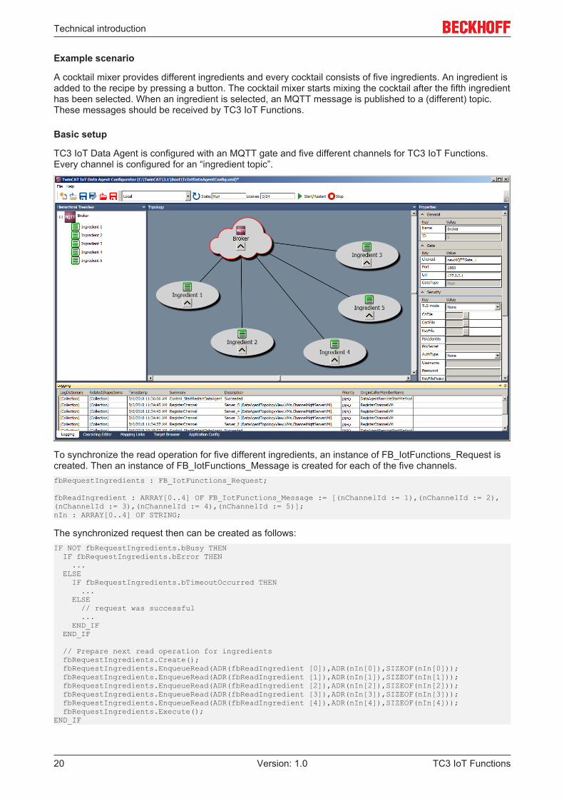
A cocktail mixer provides different ingredients and every cocktail consists of five ingredients. An ingredient isadded to the recipe by pressing a button. The cocktail mixer starts mixing the cocktail after the fifth ingredienthas been selected. When an ingredient is selected, an MQTT message is published to a (different) topic.These messages should be received by TC3 IoT Functions.
Basic setup
TC3 IoT Data Agent is configured with an MQTT gate and five different channels for TC3 IoT Functions.Every channel is configured for an “ingredient topic”.
To synchronize the read operation for five different ingredients, an instance of FB_IotFunctions_Request iscreated. Then an instance of FB_IotFunctions_Message is created for each of the five channels.fbRequestIngredients : FB_IotFunctions_Request;
fbReadIngredient : ARRAY[0..4] OF FB_IotFunctions_Message := [(nChannelId := 1),(nChannelId := 2),(nChannelId := 3),(nChannelId := 4),(nChannelId := 5)];nIn : ARRAY[0..4] OF STRING;
The synchronized request then can be created as follows:IF NOT fbRequestIngredients.bBusy THEN IF fbRequestIngredients.bError THEN ... ELSE IF fbRequestIngredients.bTimeoutOccurred THEN ... ELSE // request was successful ... END_IF END_IF
// Prepare next read operation for ingredients fbRequestIngredients.Create(); fbRequestIngredients.EnqueueRead(ADR(fbReadIngredient [0]),ADR(nIn[0]),SIZEOF(nIn[0])); fbRequestIngredients.EnqueueRead(ADR(fbReadIngredient [1]),ADR(nIn[1]),SIZEOF(nIn[1])); fbRequestIngredients.EnqueueRead(ADR(fbReadIngredient [2]),ADR(nIn[2]),SIZEOF(nIn[2])); fbRequestIngredients.EnqueueRead(ADR(fbReadIngredient [3]),ADR(nIn[3]),SIZEOF(nIn[3])); fbRequestIngredients.EnqueueRead(ADR(fbReadIngredient [4]),ADR(nIn[4]),SIZEOF(nIn[4])); fbRequestIngredients.Execute();END_IF
Technical introduction
TC3 IoT Functions 21Version: 1.0
Sample04 shows the full sample code (see Samples [} 40]).
Synchronization conditions
The function block instance fbRequest contains different synchronization conditions. These can be used todetermine whether the read operations within the request were successful, threw an error or resulted in atimeout. Note how the different timeout and retry settings can help in supporting this use case (see Timeoutsettings [} 21]).
Condition DescriptionbBusy TRUE: Request is still in progress and not all operations have been
completed successfullyFALSE: Request has been finished. To figure out if an error ortimeout occurred, further flags need to be evaluated.
bTimeoutOccurred TRUE: RequestTimeout has been triggered for at least oneoperation.FALSE: No timeout occurred.
bError TRUE: An error occurred for at least one operation.FALSE: No error occurred.
Flags of each message operation In addition, the flags (error, success, bDataAvailable,bDataChanged) of each message operation can be analyzed inorder to figure out if a request operation was successful or failed.
4.5 Timeout settingsThe function blocks of TC3 IoT Functions include several timeout settings that may help the user to handleerrors regarding the retry operations. The following section explains the different timeout settings moredetailed.
RequestTimeout
The RequestTimeout can be either set globally on an instance of FB_IotFunctions_Connector or individuallyon an instance of FB_IotFunctions_Message. Individual settings always override global settings. TheRequestTimeout closely works together with the MessageRetryInterval setting.
The RequestTimeout specifies when a message operation (read/write) will time out. For example, ifRequestTimeout is set to 10000, a read operation will time out after 10 seconds if no data has beenreceived. If data is received within 10 seconds, the operation will finish immediately.
MessageRetryInterval
The MessageRetryInterval can be either set globally on an instance of FB_IotFunctions_Connector orindividually on an instance of FB_IotFunctions_Message. Individual settings always override global settings.The MessageRetryInterval closely works together with the RequestTimeout setting.
The MessageRetryInterval specifies the time interval in [ms] when a message operation will be retried. Theupper limit of the interval is always the RequestTimeout. For example, if RequestTimeout is set to 10000 andMessageRetryInterval to 1000, a read operation will be retried ten times before the RequestTimeout istriggered and the read operation times out.
CumulativeTimeout
The CumulativeTimeout can be set on instances of FB_IotFunctions_Request when synchronizing messageoperations (see Synchronizing message operations [} 19]).
The use case is as follows (example):
• There are three read operations that should be synchronized.• Every read operation comes from a different channel

Technical introduction
TC3 IoT Functions22 Version: 1.0
• RequestTimeout is globally set to 10000 ms• CumulativeTimeout is globally set to 3000 ms• After 8000 ms the first message comes in via channel 1.• Since only 2000 ms remain until the RequestTimeout time is reached, the CumulativeTimeout is added
to the remaining RequestTimeout time, to prevent a time out of the whole request. TheRequestTimeout time is then 5000 ms. This gives the request more time to gather data via the othertwo read operations. If there is no data on the other two operations after 5000 ms, the whole requestwill time out.
Configuration
TC3 IoT Functions 23Version: 1.0
5 Configuration
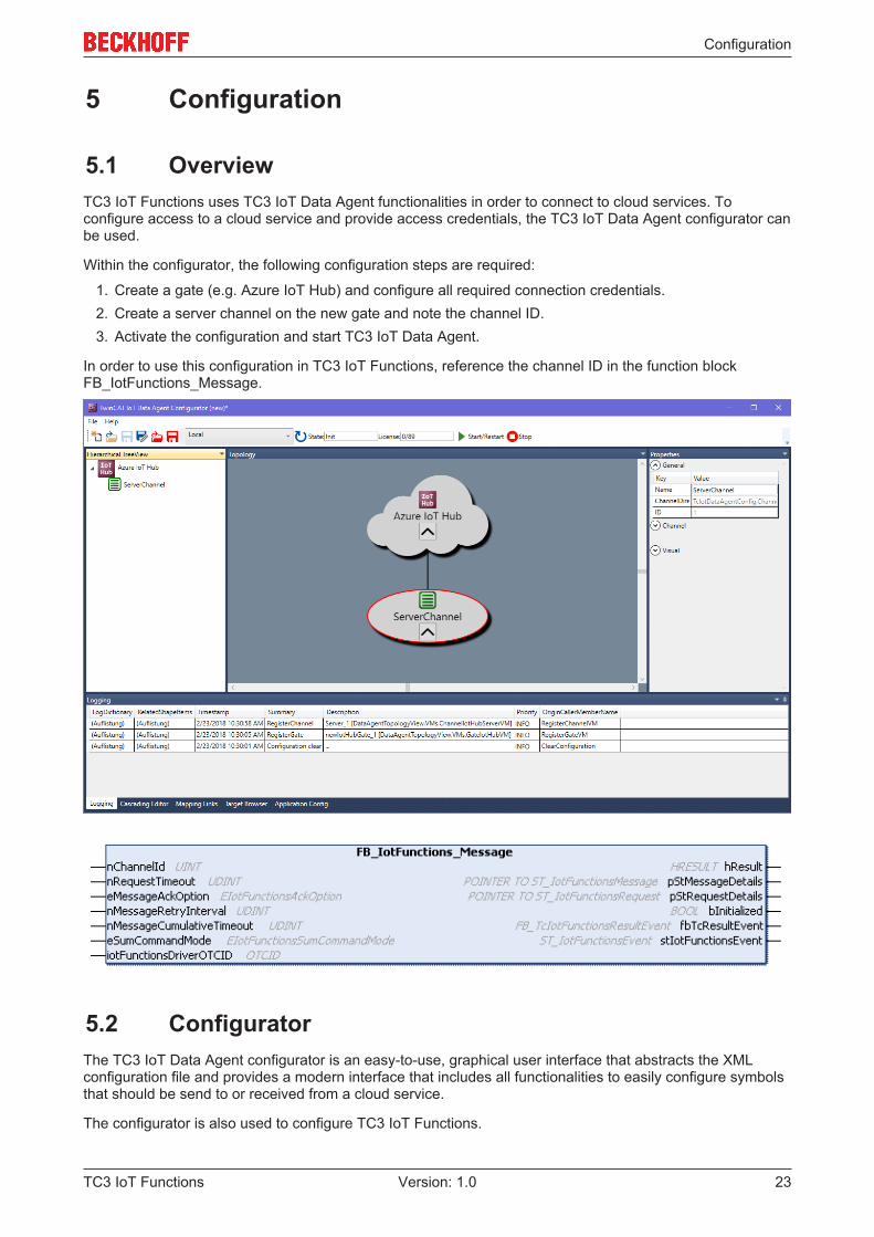
5.1 OverviewTC3 IoT Functions uses TC3 IoT Data Agent functionalities in order to connect to cloud services. Toconfigure access to a cloud service and provide access credentials, the TC3 IoT Data Agent configurator canbe used.
Within the configurator, the following configuration steps are required:
1. Create a gate (e.g. Azure IoT Hub) and configure all required connection credentials.2. Create a server channel on the new gate and note the channel ID.3. Activate the configuration and start TC3 IoT Data Agent.
In order to use this configuration in TC3 IoT Functions, reference the channel ID in the function blockFB_IotFunctions_Message.
5.2 ConfiguratorThe TC3 IoT Data Agent configurator is an easy-to-use, graphical user interface that abstracts the XMLconfiguration file and provides a modern interface that includes all functionalities to easily configure symbolsthat should be send to or received from a cloud service.
The configurator is also used to configure TC3 IoT Functions.
Configuration
TC3 IoT Functions24 Version: 1.0
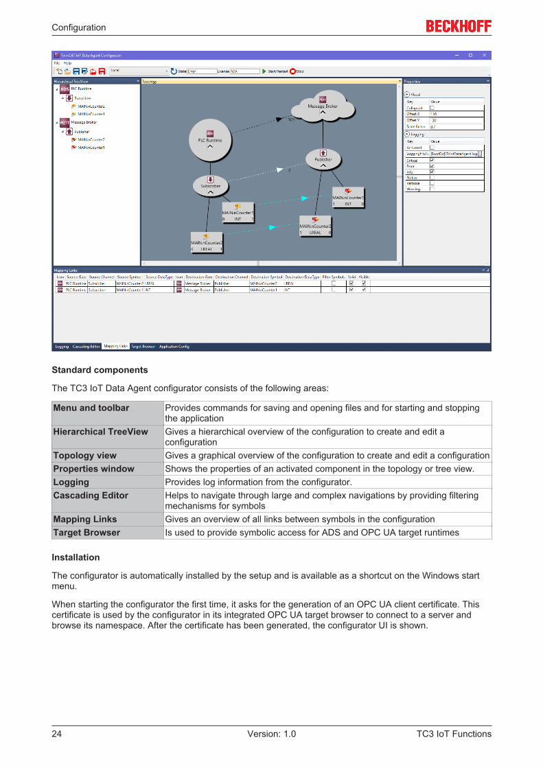
Standard components
The TC3 IoT Data Agent configurator consists of the following areas:
Menu and toolbar Provides commands for saving and opening files and for starting and stoppingthe application
Hierarchical TreeView Gives a hierarchical overview of the configuration to create and edit aconfiguration
Topology view Gives a graphical overview of the configuration to create and edit a configurationProperties window Shows the properties of an activated component in the topology or tree view.Logging Provides log information from the configurator.Cascading Editor Helps to navigate through large and complex navigations by providing filtering
mechanisms for symbolsMapping Links Gives an overview of all links between symbols in the configurationTarget Browser Is used to provide symbolic access for ADS and OPC UA target runtimes
Installation
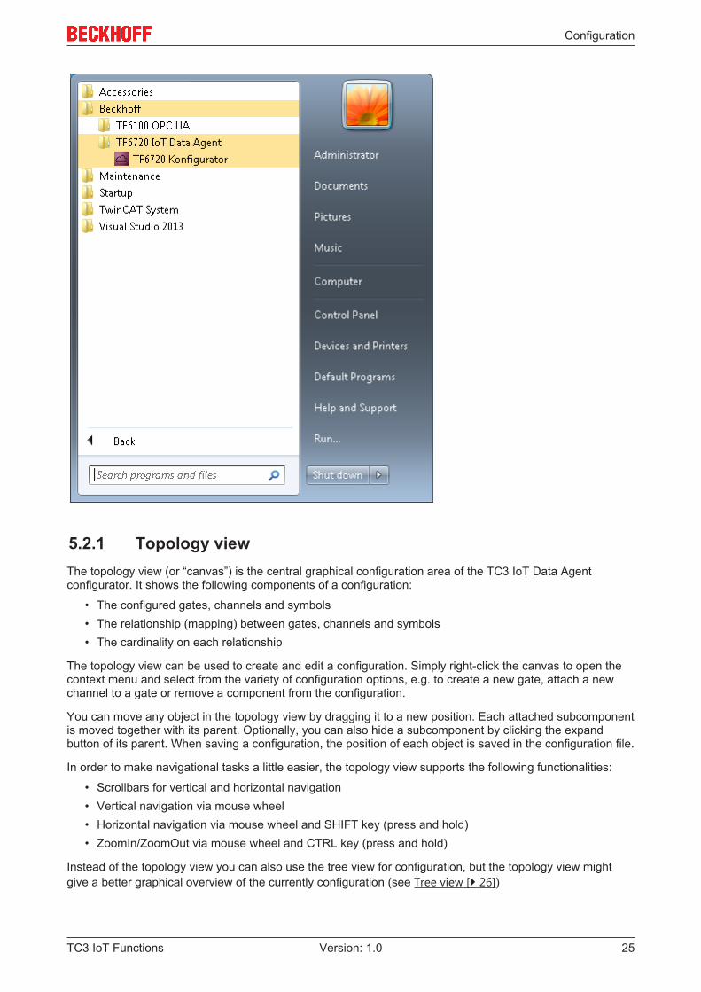
The configurator is automatically installed by the setup and is available as a shortcut on the Windows startmenu.
When starting the configurator the first time, it asks for the generation of an OPC UA client certificate. Thiscertificate is used by the configurator in its integrated OPC UA target browser to connect to a server andbrowse its namespace. After the certificate has been generated, the configurator UI is shown.
Configuration
TC3 IoT Functions 25Version: 1.0
5.2.1 Topology viewThe topology view (or “canvas”) is the central graphical configuration area of the TC3 IoT Data Agentconfigurator. It shows the following components of a configuration:
• The configured gates, channels and symbols• The relationship (mapping) between gates, channels and symbols• The cardinality on each relationship
The topology view can be used to create and edit a configuration. Simply right-click the canvas to open thecontext menu and select from the variety of configuration options, e.g. to create a new gate, attach a newchannel to a gate or remove a component from the configuration.
You can move any object in the topology view by dragging it to a new position. Each attached subcomponentis moved together with its parent. Optionally, you can also hide a subcomponent by clicking the expandbutton of its parent. When saving a configuration, the position of each object is saved in the configuration file.
In order to make navigational tasks a little easier, the topology view supports the following functionalities:
• Scrollbars for vertical and horizontal navigation• Vertical navigation via mouse wheel• Horizontal navigation via mouse wheel and SHIFT key (press and hold)• ZoomIn/ZoomOut via mouse wheel and CTRL key (press and hold)
Instead of the topology view you can also use the tree view for configuration, but the topology view mightgive a better graphical overview of the currently configuration (see Tree view [} 26])
Configuration
TC3 IoT Functions26 Version: 1.0
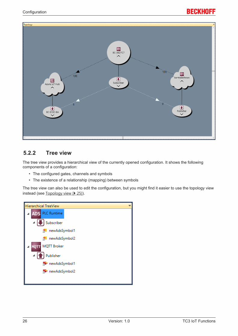
5.2.2 Tree viewThe tree view provides a hierarchical view of the currently opened configuration. It shows the followingcomponents of a configuration:
• The configured gates, channels and symbols• The existence of a relationship (mapping) between symbols
The tree view can also be used to edit the configuration, but you might find it easier to use the topology viewinstead (see Topology view [} 25]).
Configuration
TC3 IoT Functions 27Version: 1.0
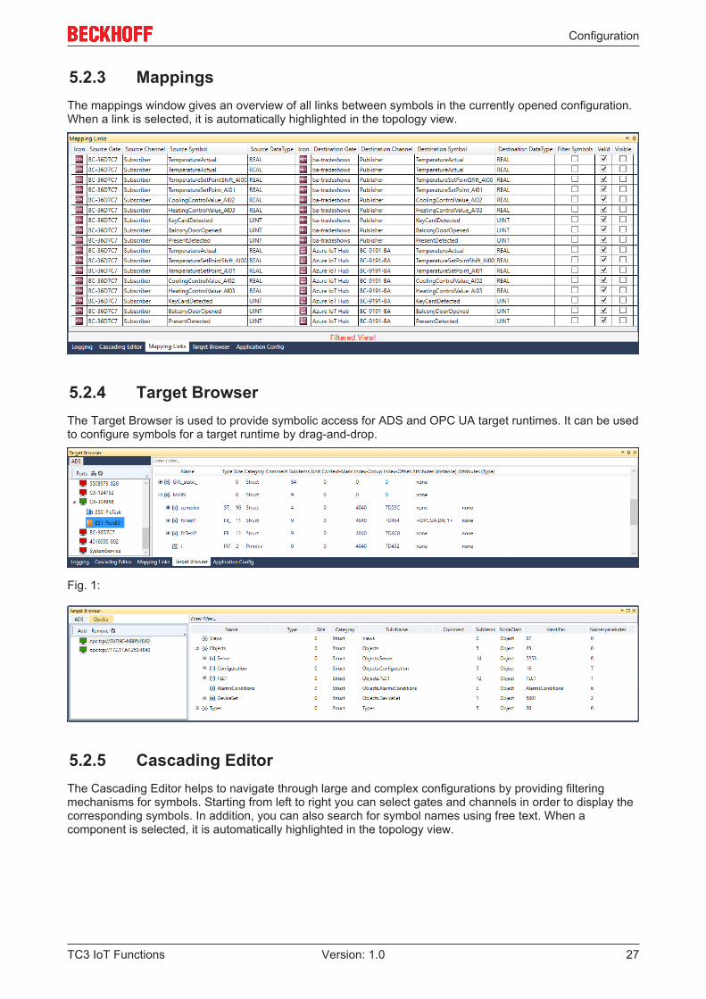
5.2.3 MappingsThe mappings window gives an overview of all links between symbols in the currently opened configuration.When a link is selected, it is automatically highlighted in the topology view.
5.2.4 Target BrowserThe Target Browser is used to provide symbolic access for ADS and OPC UA target runtimes. It can be usedto configure symbols for a target runtime by drag-and-drop.
Fig. 1:
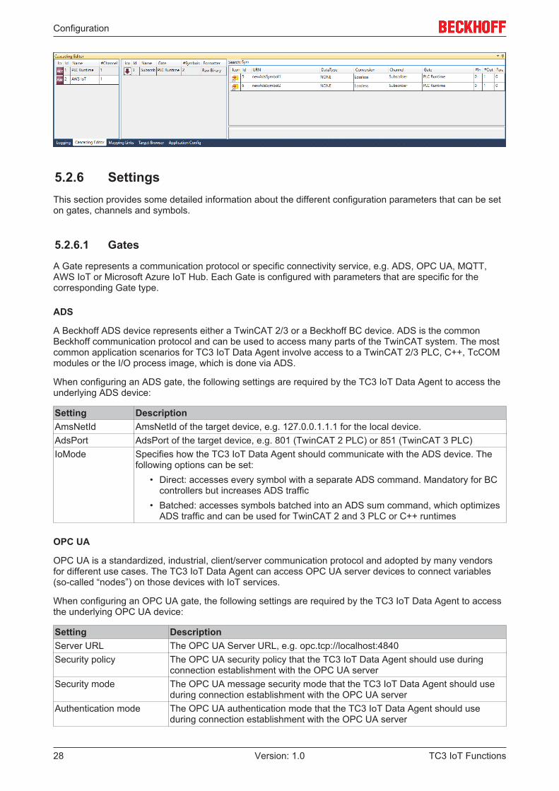
5.2.5 Cascading EditorThe Cascading Editor helps to navigate through large and complex configurations by providing filteringmechanisms for symbols. Starting from left to right you can select gates and channels in order to display thecorresponding symbols. In addition, you can also search for symbol names using free text. When acomponent is selected, it is automatically highlighted in the topology view.
Configuration
TC3 IoT Functions28 Version: 1.0
5.2.6 SettingsThis section provides some detailed information about the different configuration parameters that can be seton gates, channels and symbols.
5.2.6.1 Gates
A Gate represents a communication protocol or specific connectivity service, e.g. ADS, OPC UA, MQTT,AWS IoT or Microsoft Azure IoT Hub. Each Gate is configured with parameters that are specific for thecorresponding Gate type.
ADS
A Beckhoff ADS device represents either a TwinCAT 2/3 or a Beckhoff BC device. ADS is the commonBeckhoff communication protocol and can be used to access many parts of the TwinCAT system. The mostcommon application scenarios for TC3 IoT Data Agent involve access to a TwinCAT 2/3 PLC, C++, TcCOMmodules or the I/O process image, which is done via ADS.
When configuring an ADS gate, the following settings are required by the TC3 IoT Data Agent to access theunderlying ADS device:
Setting DescriptionAmsNetId AmsNetId of the target device, e.g. 127.0.0.1.1.1 for the local device.AdsPort AdsPort of the target device, e.g. 801 (TwinCAT 2 PLC) or 851 (TwinCAT 3 PLC)IoMode Specifies how the TC3 IoT Data Agent should communicate with the ADS device. The
following options can be set:• Direct: accesses every symbol with a separate ADS command. Mandatory for BC
controllers but increases ADS traffic• Batched: accesses symbols batched into an ADS sum command, which optimizes
ADS traffic and can be used for TwinCAT 2 and 3 PLC or C++ runtimes
OPC UA
OPC UA is a standardized, industrial, client/server communication protocol and adopted by many vendorsfor different use cases. The TC3 IoT Data Agent can access OPC UA server devices to connect variables(so-called “nodes”) on those devices with IoT services.
When configuring an OPC UA gate, the following settings are required by the TC3 IoT Data Agent to accessthe underlying OPC UA device:
Setting DescriptionServer URL The OPC UA Server URL, e.g. opc.tcp://localhost:4840Security policy The OPC UA security policy that the TC3 IoT Data Agent should use during
connection establishment with the OPC UA serverSecurity mode The OPC UA message security mode that the TC3 IoT Data Agent should use
during connection establishment with the OPC UA serverAuthentication mode The OPC UA authentication mode that the TC3 IoT Data Agent should use
during connection establishment with the OPC UA server
Configuration
TC3 IoT Functions 29Version: 1.0
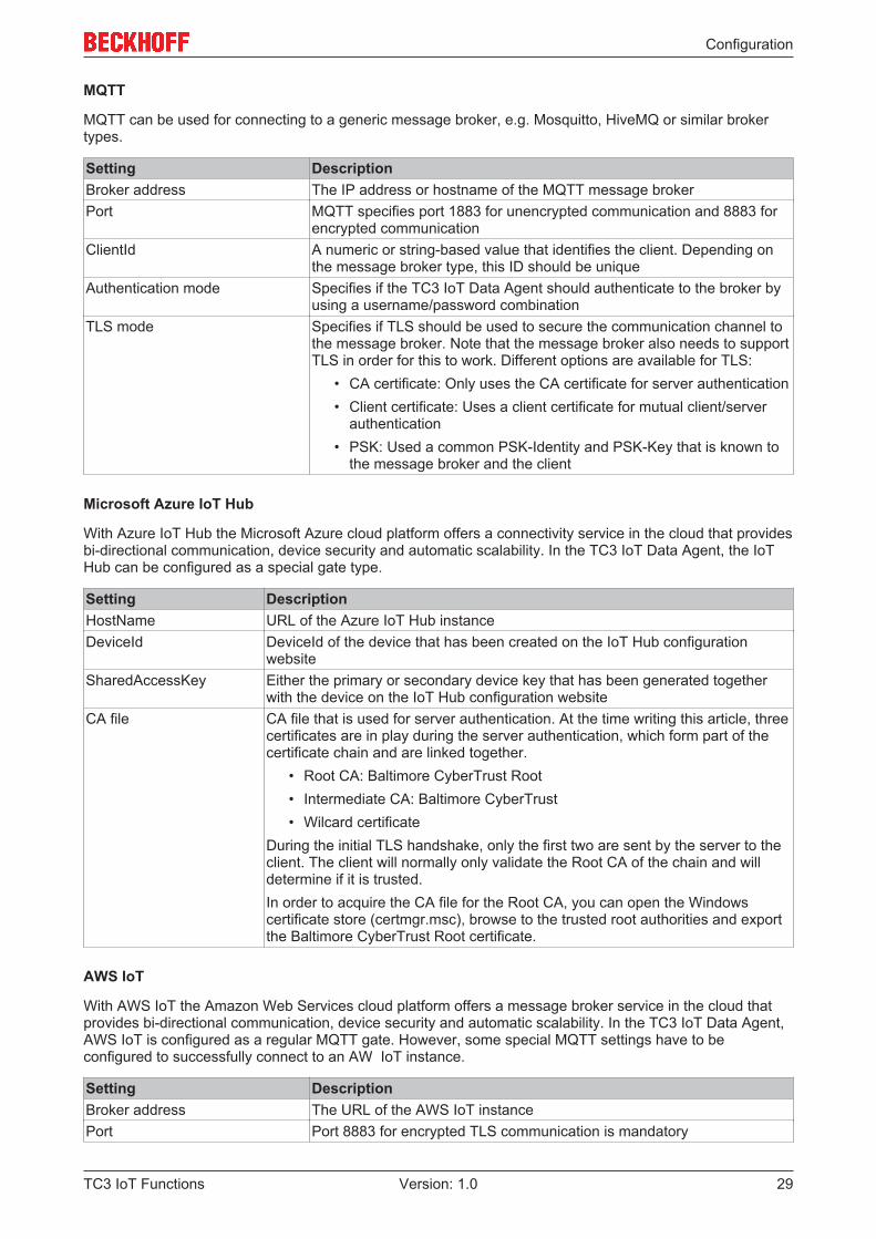
MQTT
MQTT can be used for connecting to a generic message broker, e.g. Mosquitto, HiveMQ or similar brokertypes.
Setting DescriptionBroker address The IP address or hostname of the MQTT message brokerPort MQTT specifies port 1883 for unencrypted communication and 8883 for
encrypted communicationClientId A numeric or string-based value that identifies the client. Depending on
the message broker type, this ID should be uniqueAuthentication mode Specifies if the TC3 IoT Data Agent should authenticate to the broker by
using a username/password combinationTLS mode Specifies if TLS should be used to secure the communication channel to
the message broker. Note that the message broker also needs to supportTLS in order for this to work. Different options are available for TLS:
• CA certificate: Only uses the CA certificate for server authentication• Client certificate: Uses a client certificate for mutual client/server
authentication• PSK: Used a common PSK-Identity and PSK-Key that is known to
the message broker and the client
Microsoft Azure IoT Hub
With Azure IoT Hub the Microsoft Azure cloud platform offers a connectivity service in the cloud that providesbi-directional communication, device security and automatic scalability. In the TC3 IoT Data Agent, the IoTHub can be configured as a special gate type.
Setting DescriptionHostName URL of the Azure IoT Hub instanceDeviceId DeviceId of the device that has been created on the IoT Hub configuration
websiteSharedAccessKey Either the primary or secondary device key that has been generated together
with the device on the IoT Hub configuration websiteCA file CA file that is used for server authentication. At the time writing this article, three
certificates are in play during the server authentication, which form part of thecertificate chain and are linked together.
• Root CA: Baltimore CyberTrust Root• Intermediate CA: Baltimore CyberTrust• Wilcard certificate
During the initial TLS handshake, only the first two are sent by the server to theclient. The client will normally only validate the Root CA of the chain and willdetermine if it is trusted.In order to acquire the CA file for the Root CA, you can open the Windowscertificate store (certmgr.msc), browse to the trusted root authorities and exportthe Baltimore CyberTrust Root certificate.
AWS IoT
With AWS IoT the Amazon Web Services cloud platform offers a message broker service in the cloud thatprovides bi-directional communication, device security and automatic scalability. In the TC3 IoT Data Agent,AWS IoT is configured as a regular MQTT gate. However, some special MQTT settings have to beconfigured to successfully connect to an AW IoT instance.
Setting DescriptionBroker address The URL of the AWS IoT instancePort Port 8883 for encrypted TLS communication is mandatory
Configuration
TC3 IoT Functions30 Version: 1.0
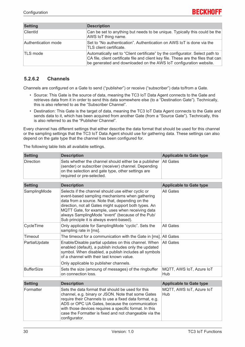
Setting DescriptionClientId Can be set to anything but needs to be unique. Typically this could be the
AWS IoT thing name.Authentication mode Set to “No authentication”. Authentication on AWS IoT is done via the
TLS client certificate.TLS mode Automatically set to “Client certificate” by the configurator. Select path to
CA file, client certificate file and client key file. These are the files that canbe generated and downloaded on the AWS IoT configuration website.
5.2.6.2 Channels
Channels are configured on a Gate to send (“publisher”) or receive (“subscriber”) data to/from a Gate.
• Source: This Gate is the source of data, meaning the TC3 IoT Data Agent connects to the Gate andretrieves data from it in order to send this data somewhere else (to a “Destination Gate”). Technically,this is also referred to as the “Subscriber Channel”.
• Destination: This Gate is the target of data, meaning the TC3 IoT Data Agent connects to the Gate andsends data to it, which has been acquired from another Gate (from a “Source Gate”). Technically, thisis also referred to as the “Publisher Channel”.
Every channel has different settings that either describe the data format that should be used for this channelor the sampling settings that the TC3 IoT Data Agent should use for gathering data. These settings can alsodepend on the gate type that the channel has been configured for.
The following table lists all available settings.
Setting Description Applicable to Gate typeDirection Sets whether the channel should either be a publisher
(sender) or subscriber (receiver) channel. Dependingon the selection and gate type, other settings arerequired or pre-selected.
All Gates
Setting Description Applicable to Gate typeSamplingMode Selects if the channel should use either cyclic or
event-based sampling mechanisms when gatheringdata from a source. Note that, depending on thedirection, not all Gates might support both types. AnMQTT Gate, for example, uses when receiving dataalways SamplingMode “event” (because of the Pub/Sub principle it is always event-based).
All Gates
CycleTime Only applicable for SamplingMode “cyclic”. Sets thesampling rate in [ms].
All Gates
Timeout The timeout for a communication with the Gate in [ms]. All GatesPartialUpdate Enable/Disable partial updates on this channel. When
enabled (default), a publish includes only the updatedsymbol. When disabled, a publish includes all symbolsof a channel with their last known value.Only applicable to publisher channels.
All Gates
BufferSize Sets the size (amoung of messages) of the ringbufferon connection loss.
MQTT, AWS IoT, Azure IoTHub
Setting Description Applicable to Gate typeFormatter Sets the data format that should be used for this
channel, e.g. binary or JSON. Note that some Gatesrequire their Channels to use a fixed data format, e.g.ADS or OPC UA Gates, because the communicationwith those devices requires a specific format. In thiscase the Formatter is fixed and not changeable via theconfigurator.
MQTT, AWS IoT, Azure IoTHub
Configuration
TC3 IoT Functions 31Version: 1.0
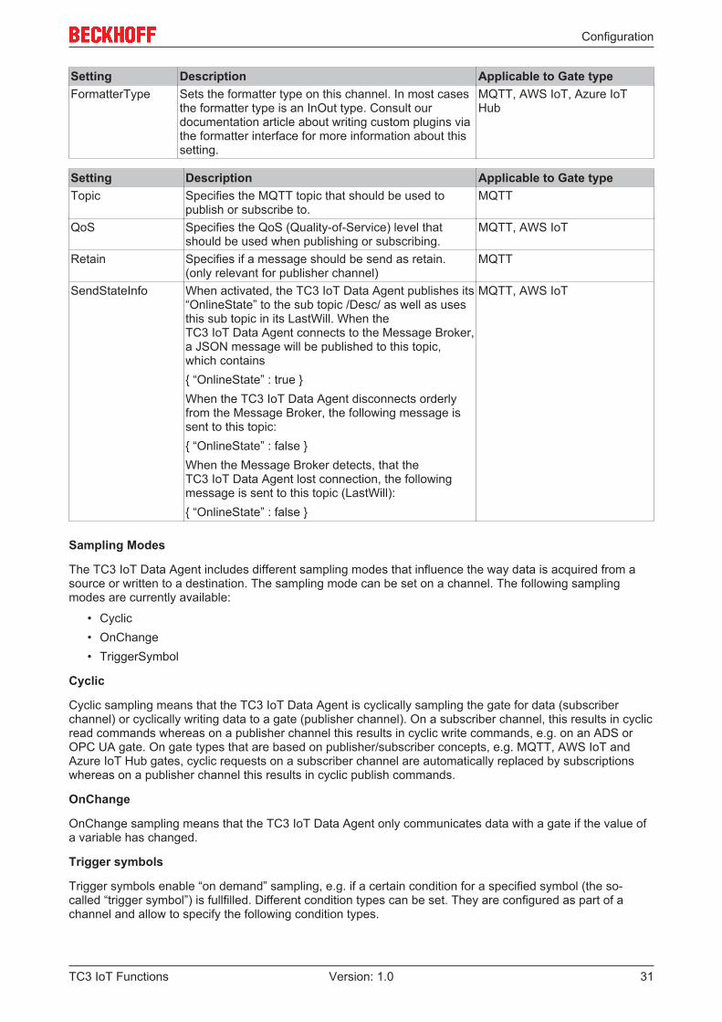
Setting Description Applicable to Gate typeFormatterType Sets the formatter type on this channel. In most cases
the formatter type is an InOut type. Consult ourdocumentation article about writing custom plugins viathe formatter interface for more information about thissetting.
MQTT, AWS IoT, Azure IoTHub
Setting Description Applicable to Gate typeTopic Specifies the MQTT topic that should be used to
publish or subscribe to.MQTT
QoS Specifies the QoS (Quality-of-Service) level thatshould be used when publishing or subscribing.
MQTT, AWS IoT
Retain Specifies if a message should be send as retain.(only relevant for publisher channel)
MQTT
SendStateInfo When activated, the TC3 IoT Data Agent publishes its“OnlineState” to the sub topic /Desc/ as well as usesthis sub topic in its LastWill. When theTC3 IoT Data Agent connects to the Message Broker,a JSON message will be published to this topic,which contains{ “OnlineState” : true }When the TC3 IoT Data Agent disconnects orderlyfrom the Message Broker, the following message issent to this topic:{ “OnlineState” : false }When the Message Broker detects, that theTC3 IoT Data Agent lost connection, the followingmessage is sent to this topic (LastWill):{ “OnlineState” : false }
MQTT, AWS IoT
Sampling Modes
The TC3 IoT Data Agent includes different sampling modes that influence the way data is acquired from asource or written to a destination. The sampling mode can be set on a channel. The following samplingmodes are currently available:
• Cyclic• OnChange• TriggerSymbol
Cyclic
Cyclic sampling means that the TC3 IoT Data Agent is cyclically sampling the gate for data (subscriberchannel) or cyclically writing data to a gate (publisher channel). On a subscriber channel, this results in cyclicread commands whereas on a publisher channel this results in cyclic write commands, e.g. on an ADS orOPC UA gate. On gate types that are based on publisher/subscriber concepts, e.g. MQTT, AWS IoT andAzure IoT Hub gates, cyclic requests on a subscriber channel are automatically replaced by subscriptionswhereas on a publisher channel this results in cyclic publish commands.
OnChange
OnChange sampling means that the TC3 IoT Data Agent only communicates data with a gate if the value ofa variable has changed.
Trigger symbols
Trigger symbols enable “on demand” sampling, e.g. if a certain condition for a specified symbol (the so-called “trigger symbol”) is fullfilled. Different condition types can be set. They are configured as part of achannel and allow to specify the following condition types.
Configuration
TC3 IoT Functions32 Version: 1.0
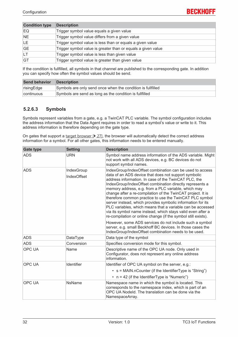
Condition type DescriptionEQ Trigger symbol value equals a given valueNE Trigger symbol value differs from a given valueLE Trigger symbol value is less than or equals a given valueGE Trigger symbol value is greater than or equals a given valueLT Trigger symbol value is less than given valueGT Trigger symbol value is greater than given value
If the condition is fullfilled, all symbols in that channel are published to the corresponding gate. In additionyou can specify how often the symbol values should be send.
Send behavior DescriptionrisingEdge Symbols are only send once when the condition is fullfilledcontinuous Symbols are send as long as the condition is fullfilled
5.2.6.3 Symbols
Symbols represent variables from a gate, e.g. a TwinCAT PLC variable. The symbol configuration includesthe address information that the Data Agent requires in order to read a symbol’s value or write to it. Thisaddress information is therefore depending on the gate type.
On gates that support a target browser [} 27], the browser will automatically detect the correct addressinformation for a symbol. For all other gates, this information needs to be entered manually.
Gate type Setting DescriptionADS URN Symbol name address information of the ADS variable. Might
not work with all ADS devices, e.g. BC devices do notsupport symbol names.
ADS IndexGroupIndexOffset
IndexGroup/IndexOffset combination can be used to accessdata of an ADS device that does not support symbolicaddress information. In case of the TwinCAT PLC, theIndexGroup/IndexOffset combination directly represents amemory address, e.g. from a PLC variable, which maychange after a re-compilation of the TwinCAT project. It istherefore common practice to use the TwinCAT PLC symbolserver instead, which provides symbolic information for itsPLC variables, which means that a variable can be accessedvia its symbol name instead, which stays valid even after are-compilation or online change (if the symbol still exists).However, some ADS services do not include such a symbolserver, e.g. small Beckhoff BC devices. In those cases theIndexGroup/IndexOffset combination needs to be used.
ADS DataType Data type of the symbolADS Conversion Specifies conversion mode for this symbol.OPC UA Name Descriptive name of the OPC UA node. Only used in
Configurator, does not represent any online addressinformation.
OPC UA Identifier Identifier of OPC UA symbol on the server, e.g.:• s = MAIN.nCounter (if the IdentifierType is “String”)• n = 42 (if the IdentifierType is “Numeric”)
OPC UA NsName Namespace name in which the symbol is located. Thiscorresponds to the namespace index, which is part of anOPC UA NodeId. The translation can be done via theNamespaceArray.
Configuration
TC3 IoT Functions 33Version: 1.0
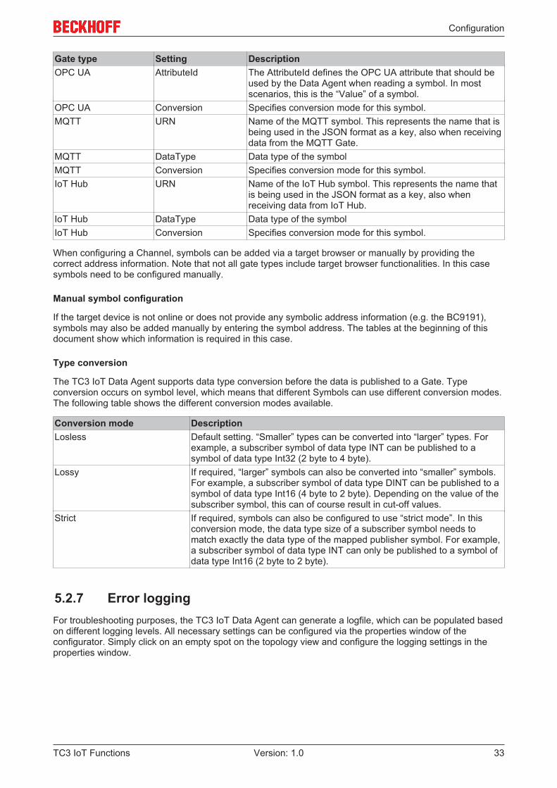
Gate type Setting DescriptionOPC UA AttributeId The AttributeId defines the OPC UA attribute that should be
used by the Data Agent when reading a symbol. In mostscenarios, this is the “Value” of a symbol.
OPC UA Conversion Specifies conversion mode for this symbol.MQTT URN Name of the MQTT symbol. This represents the name that is
being used in the JSON format as a key, also when receivingdata from the MQTT Gate.
MQTT DataType Data type of the symbolMQTT Conversion Specifies conversion mode for this symbol.IoT Hub URN Name of the IoT Hub symbol. This represents the name that
is being used in the JSON format as a key, also whenreceiving data from IoT Hub.
IoT Hub DataType Data type of the symbolIoT Hub Conversion Specifies conversion mode for this symbol.
When configuring a Channel, symbols can be added via a target browser or manually by providing thecorrect address information. Note that not all gate types include target browser functionalities. In this casesymbols need to be configured manually.
Manual symbol configuration
If the target device is not online or does not provide any symbolic address information (e.g. the BC9191),symbols may also be added manually by entering the symbol address. The tables at the beginning of thisdocument show which information is required in this case.
Type conversion
The TC3 IoT Data Agent supports data type conversion before the data is published to a Gate. Typeconversion occurs on symbol level, which means that different Symbols can use different conversion modes.The following table shows the different conversion modes available.
Conversion mode DescriptionLosless Default setting. “Smaller” types can be converted into “larger” types. For
example, a subscriber symbol of data type INT can be published to asymbol of data type Int32 (2 byte to 4 byte).
Lossy If required, “larger” symbols can also be converted into “smaller” symbols.For example, a subscriber symbol of data type DINT can be published to asymbol of data type Int16 (4 byte to 2 byte). Depending on the value of thesubscriber symbol, this can of course result in cut-off values.
Strict If required, symbols can also be configured to use “strict mode”. In thisconversion mode, the data type size of a subscriber symbol needs tomatch exactly the data type of the mapped publisher symbol. For example,a subscriber symbol of data type INT can only be published to a symbol ofdata type Int16 (2 byte to 2 byte).
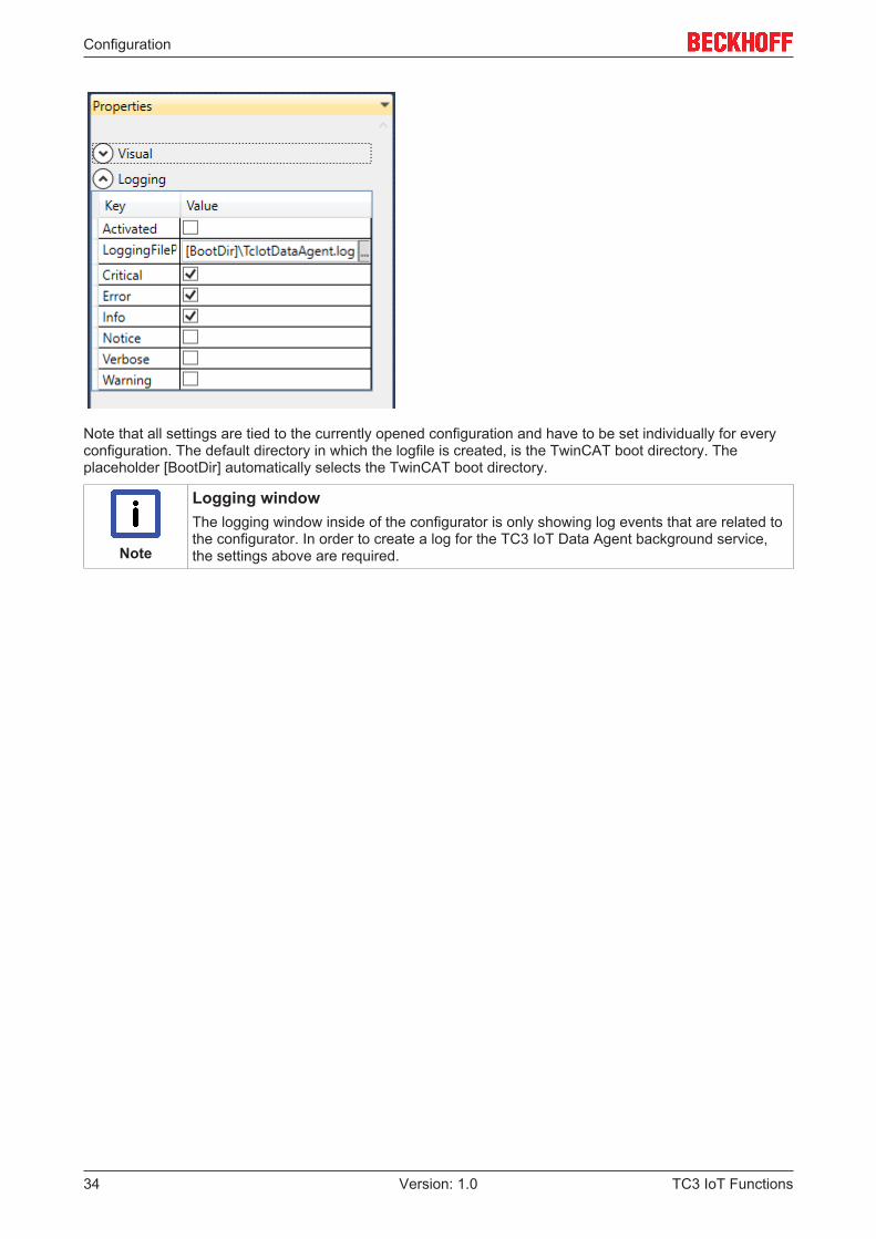
5.2.7 Error loggingFor troubleshooting purposes, the TC3 IoT Data Agent can generate a logfile, which can be populated basedon different logging levels. All necessary settings can be configured via the properties window of theconfigurator. Simply click on an empty spot on the topology view and configure the logging settings in theproperties window.
Configuration
TC3 IoT Functions34 Version: 1.0
Note that all settings are tied to the currently opened configuration and have to be set individually for everyconfiguration. The default directory in which the logfile is created, is the TwinCAT boot directory. Theplaceholder [BootDir] automatically selects the TwinCAT boot directory.
Note
Logging windowThe logging window inside of the configurator is only showing log events that are related tothe configurator. In order to create a log for the TC3 IoT Data Agent background service,the settings above are required.
PLC API
TC3 IoT Functions 35Version: 1.0
6 PLC API
6.1 Function blocks
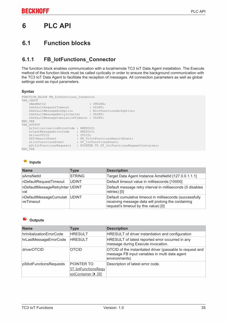
6.1.1 FB_IotFunctions_ConnectorThe function block enables communication with a local/remote TC3 IoT Data Agent installation. The Executemethod of the function block must be called cyclically in order to ensure the background communication withthe TC3 IoT Data Agent to facilitate the reception of messages. All connection parameters as well as globalsettings exist as input parameters.
SyntaxFUNCTION_BLOCK FB_IotFunctions_ConnectorVAR_INPUT sAmsNetId : STRING; nDefaultRequestTimeout : UDINT; eDefaultMessageAckOption : EIotFunctionsAckOption; nDefaultMessageRetryInterval : UDINT; nDefaultMessageCumulativeTimeout : UDINT;END_VARVAR_OUTPUT hrInitializationErrorCode : HRESULT; hrLastMessageErrorCode : HRESULT; driverOTCID : OTCID; fbTcResultEvent : FB_TcIotFunctionsResultEvent; stIotFunctionsEvent : ST_IotFunctionsEvent; pStIotFunctionsRequests : POINTER TO ST_IotFunctionsRequestContainer;END_VAR
Inputs
Name Type DescriptionsAmsNetId STRING Target Data Agent Instance AmsNetId [127.0.0.1.1.1]nDefaultRequestTimeout UDINT Default timeout value in milliseconds [10000]nDefaultMessageRetryInterval
UDINT Default message retry interval in milliseconds (0 disablesretries) [0]
nDefaultMessageCumulativeTimeout
UDINT Default cumulative timeout in milliseconds (successfullyreceiving message data will prolong the containingrequest's timeout by this value) [0]
Outputs
Name Type DescriptionhrInitializationErrorCode HRESULT HRESULT of driver instantiation and configurationhrLastMessageErrorCode HRESULT HRESULT of latest reported error occurred in any
message during Execute invocation.driverOTCID OTCID OTCID of the instantiated driver (passable to request and
message FB input variables in multi data agentenvironments)
pStIotFunctionsRequests POINTER TOST_IotFunctionsRequestContainer [} 39]
Description of latest error code.
PLC API
TC3 IoT Functions36 Version: 1.0
Methods
Name DescriptionExecute Enables background communication with TC3 IoT Data Agent. The method
must be called cyclically.
Requirements
Development environment Target platform PLC libraries to includeTwinCAT v3.1.4022.14 IPC or CX (c86, x64, ARM) Tc3_IotFunctions
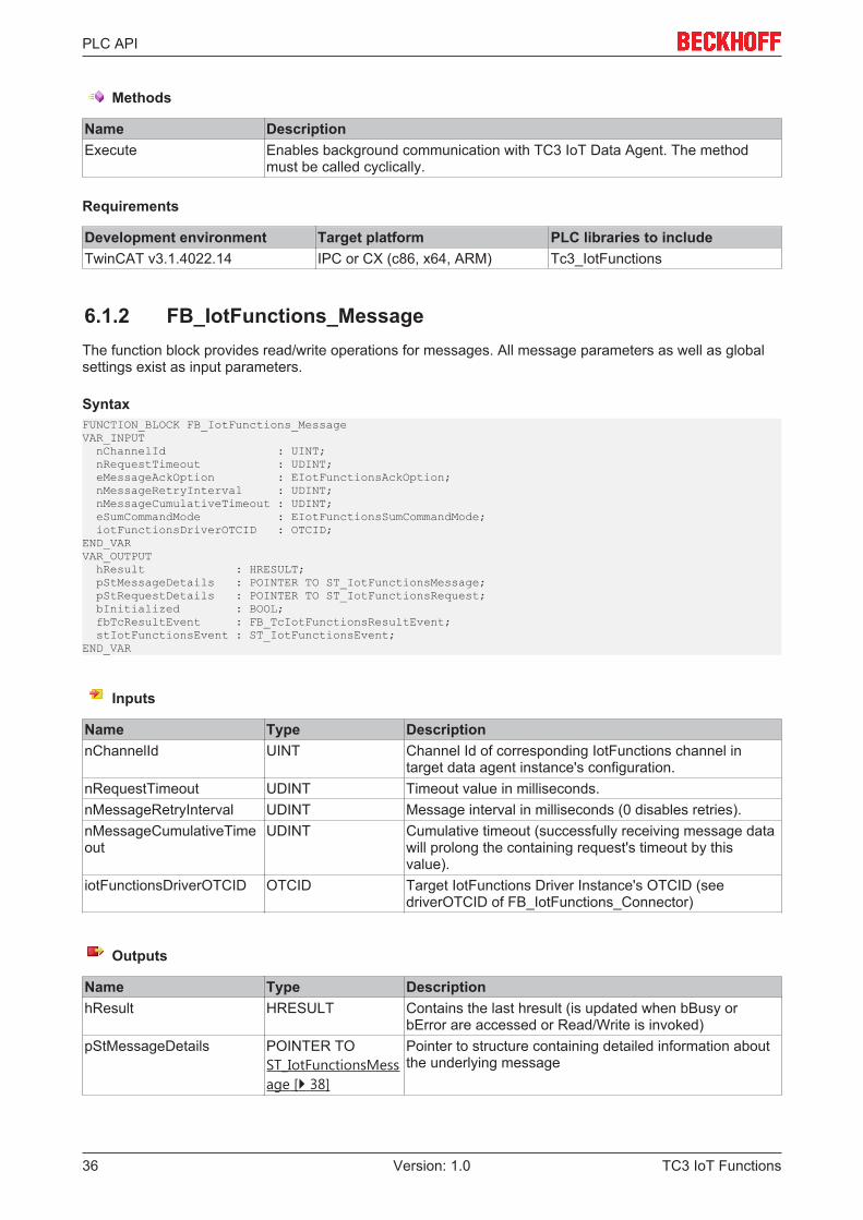
6.1.2 FB_IotFunctions_MessageThe function block provides read/write operations for messages. All message parameters as well as globalsettings exist as input parameters.
SyntaxFUNCTION_BLOCK FB_IotFunctions_MessageVAR_INPUT nChannelId : UINT; nRequestTimeout : UDINT; eMessageAckOption : EIotFunctionsAckOption; nMessageRetryInterval : UDINT; nMessageCumulativeTimeout : UDINT; eSumCommandMode : EIotFunctionsSumCommandMode; iotFunctionsDriverOTCID : OTCID;END_VARVAR_OUTPUT hResult : HRESULT; pStMessageDetails : POINTER TO ST_IotFunctionsMessage; pStRequestDetails : POINTER TO ST_IotFunctionsRequest; bInitialized : BOOL; fbTcResultEvent : FB_TcIotFunctionsResultEvent; stIotFunctionsEvent : ST_IotFunctionsEvent;END_VAR
Inputs
Name Type DescriptionnChannelId UINT Channel Id of corresponding IotFunctions channel in
target data agent instance's configuration.nRequestTimeout UDINT Timeout value in milliseconds.nMessageRetryInterval UDINT Message interval in milliseconds (0 disables retries).nMessageCumulativeTimeout
UDINT Cumulative timeout (successfully receiving message datawill prolong the containing request's timeout by thisvalue).
iotFunctionsDriverOTCID OTCID Target IotFunctions Driver Instance's OTCID (seedriverOTCID of FB_IotFunctions_Connector)
Outputs
Name Type DescriptionhResult HRESULT Contains the last hresult (is updated when bBusy or
bError are accessed or Read/Write is invoked)pStMessageDetails POINTER TO
ST_IotFunctionsMessage [} 38]
Pointer to structure containing detailed information aboutthe underlying message
PLC API
TC3 IoT Functions 37Version: 1.0
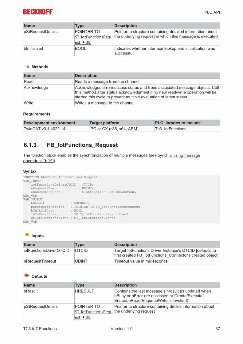
Name Type DescriptionpStRequestDetails POINTER TO
ST_IotFunctionsRequest [} 39]
Pointer to structure containing detailed information aboutthe underlying request in which this message is executed
bInitialized BOOL Indicates whether interface lookup and initialization wassuccessful
Methods
Name DescriptionRead Reads a message from the channelAcknowledge Acknowledges error/success status and frees associated message objects. Call
this method after status acknowledgment if no new read/write operation will bestarted this cycle to prevent multiple evaluation of latest status.
Write Writes a message to the channel
Requirements
Development environment Target platform PLC libraries to includeTwinCAT v3.1.4022.14 IPC or CX (c86, x64, ARM) Tc3_IotFunctions
6.1.3 FB_IotFunctions_RequestThe function block enables the synchronization of multiple messages (see Synchronizing messageoperations [} 19]).
SyntaxFUNCTION_BLOCK FB_IotFunctions_RequestVAR_INPUT iotFunctionsDriverOTCID : OTCID; nRequestTimeout : UDINT; eSumCommandMode : EIotFunctionsSumCommandMode;END_VARVAR_OUTPUT hResult : HRESULT; pStRequestDetails : POINTER TO ST_IotFunctionsRequest; bInitialized : BOOL; fbTcResultEvent : FB_TcIotFunctionsResultEvent; stIotFunctionsEvent : ST_IotFunctionsEvent;END_VAR
Inputs
Name Type DescriptioniotFunctionsDriverOTCID OTCID Target IotFunctions Driver Instance's OTCID [defaults to
first created FB_IotFunctions_Connector's created object]nRequestTimeout UDINT Timeout value in milliseconds
Outputs
Name Type DescriptionhResult HRESULT Contains the last message's hresult (is updated when
bBusy or bError are accessed or Create/Execute/EnqueueRead/EnqueueWrite is invoked)
pStRequestDetails POINTER TOST_IotFunctionsRequest [} 39]
Pointer to structure containing details information aboutthe underlying request
PLC API
TC3 IoT Functions38 Version: 1.0
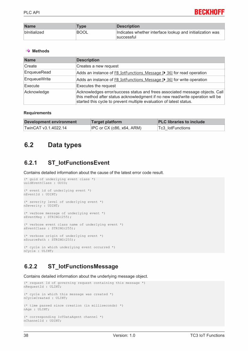
Name Type DescriptionbInitialized BOOL Indicates whether interface lookup and initialization was
successful
Methods
Name DescriptionCreate Creates a new requestEnqueueRead Adds an instance of FB_IotFunctions_Message [} 36] for read operationEnqueueWrite Adds an instance of FB_IotFunctions_Message [} 36] for write operationExecute Executes the requestAcknowledge Acknowledges error/success status and frees associated message objects. Call
this method after status acknowledgment if no new read/write operation will bestarted this cycle to prevent multiple evaluation of latest status.
Requirements
Development environment Target platform PLC libraries to includeTwinCAT v3.1.4022.14 IPC or CX (c86, x64, ARM) Tc3_IotFunctions
6.2 Data types
6.2.1 ST_IotFunctionsEventContains detailed information about the cause of the latest error code result.(* guid of underlying event class *)uuidEventClass : GUID;
(* event id of underlying event *)nEventId : UDINT;
(* severity level of underlying event *)nSeverity : UDINT;
(* verbose message of underlying event *)sEventMsg : STRING(255);
(* verbose event class name of underlying event *)sEventClass : STRING(255);
(* verbose origin of underlying event *)sSourcePath : STRING(255);
(* cycle in which underlying event occurred *)nCycle : ULINT;
6.2.2 ST_IotFunctionsMessageContains detailed information about the underlying message object.(* request Id of governing request containing this message *)nRequestId : ULINT;
(* cycle in which this message was created *)nCycleCreated : ULINT;
(* time passed since creation (in milliseconds) *)nAge : ULINT;
(* corresponding IoTDataAgent channel *)nChannelId : UDINT;
PLC API
TC3 IoT Functions 39Version: 1.0
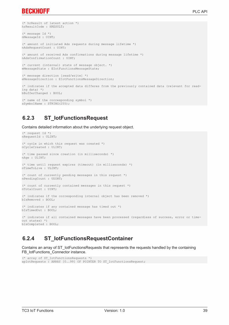
(* hrResult of latest action *)hrResultCode : HRESULT;
(* message Id *)nMessageId : UINT;
(* amount of initiated Ads requests during message lifetime *)nAdsRequestCount : UINT;
(* amount of received Ads confirmations during message lifetime *)nAdsConfirmationCount : UINT;
(* current (internal) state of message object. *)eMessageState : EIotFunctionsMessageState;
(* message direction [read/write] *)eMessageDirection : EIotFunctionsMessageDirection;
(* indicates if the accepted data differes from the previously contained data (relevant for read-ing data) *)bBufferChanged : BOOL;
(* name of the corresponding symbol *)sSymbolName : STRING(255);
6.2.3 ST_IotFunctionsRequestContains detailed information about the underlying request object.(* request Id *)nRequestId : ULINT;
(* cycle in which this request was created *)nCycleCreated : ULINT;
(* time passed since creation (in milliseconds) *)nAge : ULINT;
(* time until request expires (timeout) (in milliseconds) *)nTimeToLive : ULINT;
(* count of currently pending messages in this request *)nPendingCount : UDINT;
(* count of currently contained messages in this request *)nTotalCount : UINT;
(* indicates if the corresponding internal object has been removed *)bIsRemoved : BOOL;
(* indicates if any contained message has timed out *)bIsTimedOut : BOOL;
(* indicates if all contained messages have been processed (regardless of success, error or time-out states) *)bIsCompleted : BOOL;
6.2.4 ST_IotFunctionsRequestContainerContains an array of ST_IotFunctionsRequests that represents the requests handled by the containingFB_IotFunctions_Connector instance.(* array of ST_IotFunctionsRequests *)apIotRequests : ARRAY [0..99] OF POINTER TO ST_IotFunctionsRequest;

Samples
TC3 IoT Functions40 Version: 1.0
7 SamplesSamples for TC3 IoT Functions can be downloaded as a single container solution: https://infosys.beckhoff.com/content/1033/tf6710_tc3_iot_functions/Resources/zip/5247017867.zip
Appendix
TC3 IoT Functions 41Version: 1.0
8 Appendix
8.1 Support and ServiceBeckhoff and their partners around the world offer comprehensive support and service, making available fastand competent assistance with all questions related to Beckhoff products and system solutions.
Beckhoff's branch offices and representatives
Please contact your Beckhoff branch office or representative for local support and service on Beckhoffproducts!
The addresses of Beckhoff's branch offices and representatives round the world can be found on her internetpages:http://www.beckhoff.com
You will also find further documentation for Beckhoff components there.
Beckhoff Headquarters
Beckhoff Automation GmbH & Co. KG
Huelshorstweg 2033415 VerlGermany
Phone: +49(0)5246/963-0Fax: +49(0)5246/963-198e-mail: [email protected]
Beckhoff Support
Support offers you comprehensive technical assistance, helping you not only with the application ofindividual Beckhoff products, but also with other, wide-ranging services:
• support• design, programming and commissioning of complex automation systems• and extensive training program for Beckhoff system components
Hotline: +49(0)5246/963-157Fax: +49(0)5246/963-9157e-mail: [email protected]
Beckhoff Service
The Beckhoff Service Center supports you in all matters of after-sales service:
• on-site service• repair service• spare parts service• hotline service
Hotline: +49(0)5246/963-460Fax: +49(0)5246/963-479e-mail: [email protected]