Manual Plant 4D Athena SP2 - Pipe-master
70
Plant 4D Athena SP2 Pipe Manual Version 1.2 © Copyright 1996-2007 CEA Technology B.V., The Netherlands
Transcript of Manual Plant 4D Athena SP2 - Pipe-master

Plant 4D Athena SP2
P i p e M a n u a lVersion 1.2
© Copyright 1996-2007 CEA Technology B.V., The Netherlands
Table of contents
1. Introduction.......................................................................................21.1. Legal notice ......................................................................................................... 21.2. About Plant-4D .................................................................................................... 21.3. Installing the Software..........................................................................................31.4. Projects................................................................................................................31.5. Creating new drawings.........................................................................................31.6. Starting Plant-4D Pipe..........................................................................................31.7. Plant-4D Toolbars ................................................................................................5
1.7.1. Plant-4D Pipe Toolbar...............................................................................................51.7.4. Modify Toolbar..........................................................................................................61.7.7. Settings Toolbar........................................................................................................71.7.10. Component Toolbars................................................................................................7
1.8. Plant-4D P&ID Menu............................................................................................91.9. Add-on Modules................................................................................................... 9
1.9.1. AutoCAD ..................................................................................................................91.9.2. MicroStation..............................................................................................................9
2. Functions of Plant-4D Pipe............................................................102.1. Placement of components.................................................................................. 102.2. Placement of pipeline components..................................................................... 10
2.2.1. Continue on an existing component .........................................................................112.2.2. Place the first component on a line ..........................................................................122.2.3. Relative to an existing component ...........................................................................122.2.6. Place components aligned to existing components...................................................132.2.9. Route pipe by selecting components........................................................................152.2.11. Olet placement routine ...........................................................................................16
2.3. Drawing router lines ........................................................................................... 172.3.3. Continue router line.................................................................................................18
2.4. User Coordinate System (AutoCAD only) ........................................................... 182.5. Automatic drawing of router lines ....................................................................... 182.6. Using Tags ........................................................................................................ 20
2.6.1. Tag structure and Customization .............................................................................202.6.2. Listed tag parts .......................................................................................................202.6.3. Linking components ................................................................................................212.6.4. Virtual Tags ............................................................................................................21
2.7. Plant-4D Parent-child link................................................................................... 222.8. Plant-4D Undo-Redo.......................................................................................... 22
3. Additional Plant-4D Functions ......................................................233.1. Tools.................................................................................................................. 23

3.2. Centerline Function............................................................................................ 233.3. Componentbuilder.............................................................................................. 253.4. Elbolet Function ................................................................................................. 26
3.4.1. Select Procedure ....................................................................................................273.4.2. Placement Procedure..............................................................................................273.4.3. Placement Methods ................................................................................................293.4.8. Elbolet Component .................................................................................................323.4.9. Specification ...........................................................................................................333.4.10. Settings .................................................................................................................33
3.5. About the PIPE Menu......................................................................................... 343.6. UCS Box Functions............................................................................................ 34
4. Example of a Plant-4D Pipe Drawing............................................354.1. Information Level ............................................................................................... 42
4.1.1. Set the information level ..........................................................................................43
4.2. The Tag number dialog ...................................................................................... 434.2.1. Edit Tag number .....................................................................................................44
4.3. Data Dialog........................................................................................................ 454.3.1. Common and Solo Data ..........................................................................................454.3.2. Edit Common and Solo Data ...................................................................................45
4.4. Change Properties ............................................................................................. 464.5. Plant-4D Refresh ............................................................................................... 474.6. Reference Drawings........................................................................................... 474.7. Modify Commands ............................................................................................. 48
4.7.3. Erase......................................................................................................................494.7.4. Rotate ....................................................................................................................494.7.5. Stretch....................................................................................................................494.7.6. Copy ......................................................................................................................494.7.7. Move ......................................................................................................................504.7.8. Change Properties (AutoCAD only) .........................................................................50
4.8. Pipeline settings in Plant-4D Pipe....................................................................... 504.8.1. Settings general......................................................................................................504.8.2. Set Specification .....................................................................................................514.8.5. Set Diameter...........................................................................................................524.8.6. Set Line Number.....................................................................................................524.8.9. Auto Settings ..........................................................................................................534.8.10. Automatic gaskets, weldgaps and bolts...................................................................534.8.11. Information level.....................................................................................................534.8.12. Take over pipe settings ..........................................................................................54
4.9. Equipment ......................................................................................................... 544.9.6. Edit equipment........................................................................................................56
4.10. Highlighting and selecting components ........................................................... 564.11. Creating a 2D layout from the 3D model ......................................................... 57
4.11.1. Generation.............................................................................................................57

5. Isometrics........................................................................................625.1. Creating isometrics ............................................................................................ 625.2. Plant-4D to Iso ................................................................................................... 63
5.2.1. Making selections ...................................................................................................64
5.3. Creating the isometric ........................................................................................ 645.3.1. Viewing the Isometric(s) ..........................................................................................66
5.4. Options .............................................................................................................. 665.4.1. Transformation........................................................................................................665.4.2. Displacement..........................................................................................................675.4.3. Node Checking .......................................................................................................675.4.4. Errors .....................................................................................................................67
Plant 4D Athena SP2 ê Pipe Manual
1 Introduction ê Legal notice Page 2 of 70
1. Introduction
1.1. Legal noticeThis publication or parts thereof, may not be reproduced in any form, by any method, for any purpose
without the express written consent of CEA Technology.
CEA Technology makes no warranty of any kind with regard to this material, including, but not limited to,
the implied warranties of merchantability and fitness for a particular purpose.
CEA Technology, or any of its subsidiaries, shall not be liable for errors contained herein or for incidental
or consequential damages in connection with the furnishing, performance, or use of this material.
The information contained in this document is subject to change without notice. The name Plant-4D® is a
registered trademark of CEA Technology B.V., The Netherlands.
If you have any questions during the installation or operation, please contact your local Plant-4D dealer or
visit the CEA website for more information:
© Copyright 1996-2007 CEA Technology B.V., The Netherlands
1.2. About Plant-4DPlant-4D is a modern database-driven and object-oriented CAD system intended for the production of
P&ID and Piping drawings as well as the complete maintenance of the data related to all aspects of the
project work.
Database-driven means that both all graphics and primitives as well as data are stored in a relational
database (RDBMS). This approach has the following advantages:
¡ The program can be run on a network by a group of engineers, or a single user can work with it on a
stand-alone machine.
¡ The program can run simultaneously on AutoCAD and Microstation. Part of the drawing can be made
in Microstation, be revised in AutoCAD by another party, the drawing can be finished in Microstation,
and be delivered to the customer as an AutoCAD drawing, for instance. The CAD program is only
used to display the drawings, to serve as an interface where the drafting occurs, and to enter the
data through data entry windows. In other words, Plant-4D is CAD platform independent.¡ The drawing can be completely created or reworked by manipulating the data in the database.
¡ Interfaces to simulation programs, such as ChemCAD exist.
¡ Interfaces to instrumentation systems such as INtools exist.
¡ Translation tools to import existing CAD drawings from non-database systems exist.
¡ Interfaces to other database-driven CAD systems are feasible.
¡ Interfaces to Plant Management systems are feasible.
¡ Reporting is highly customizable through a variety of database reporting tools.
¡ Object oriented means that the elements used for drawing (for instance symbols or lines) are stored
in the database as objects:

Plant 4D Athena SP2 ê Pipe Manual
1 Introduction ê Installing the Software Page 3 of 70
Creating your own symbols is extremely easy, and can be done from the CAD program or at the
database level
There is no graphical storage. A large drawing or a model doesn’t need to be saved, as every
object is saved to the database at the moment it is inserted in CAD. Any possible crash of
Windows or lack of power supply will not affect the work done so far.
Objects can inherit properties. For instance, a control valve can inherit process and mechanical
data from the pipe it is located on. This means that less work is needed to complete all
necessary data.
The object-oriented concept makes it easy to transfer the data and do the reporting.
1.3. Installing the SoftwareBefore working with Plant-4D Pipe, the software has to be installed on your computer. In addition, there
are several configuration options that need to be set prior to using the software. These instructions are
provided in the Installation Guide.
1.4. ProjectsPlant-4D is project based. This means that a project needs to be created and/or started in order to start
working. To create and maintain projects you have to use the 4D-Explorer. See the 4D-Explorer User
Guide for more information about projects.
1.5. Creating new drawingsPlant-4D does not store AutoCAD and/or MicroStation drawings. After you have created a project with the
4D-Explorer, you have to create a drawing in the project database. This is automatically done by the 4D-
Explorer.
With the aid of AutoCAD and/or MicroStation you can make a drawing by drafting pipe, placing elbows,
etc. The structure of each component will be stored in the project database. You can find more information
about drawings in the 4D-Explorer User Guide.
1.6. Starting Plant-4D PipeTo create a model in the Plant-4D Pipe module, start the 4D-Explorer. After logging in the 4D-Explorer, the
project(s) are displayed in the Projects-tree.
By opening a project tree, the tree 3D Models become available. By a click with the right hand mouse
button and selecting New drawing from the appearing popup menu, a new drawing will be created in the
selected project.

Plant 4D Athena SP2 ê Pipe Manual
1 Introduction ê Starting Plant-4D Pipe Page 4 of 70
By clicking the right mouse button on the new drawing and selecting the Start option, as shown above, the
icons of AutoCAD and/or MicroStation become available. Double click the required application.
Error! Objects cannot be created from editing field codes.Note: Plant-4D determines whether you use AutoCAD, Microstation or both. Depending on the availability of these systems, icons will be presented in the “Start Application” dialog.
The following screen appears:
AutoCAD…
The layout of the screen is loaded from a default template file; Plant4D.dwt and is located in
<drive>:\CEA\Plant4D\Acad\PIP\Bin\. This template file is user definable.
Microstation…
Piping component toolbars
Equipment toolbars
Current settings menu
Plant-4D main (PIPE) toolbar
Plant-4D floating menu

Plant 4D Athena SP2 ê Pipe Manual
1 Introduction ê Plant-4D Toolbars Page 5 of 70
The layout of the screen is loaded from a default template file; Plant4D.dgn and is located in
<drive>:\CEA\Plant-4D\UStation\PIP\BIN. This template file is user definable
1.7. Plant-4D ToolbarsAll essential functionality in Plant-4D Pipe is started by from the Plant-4D toolbars. In the following
paragraphs all essential toolbars are explained.
1.7.1. Plant-4D Pipe ToolbarThe Plant-4D (Pipe) toolbar looks as shown below and is usually found at the bottom of your screen.
1.7.2. AutoCAD
The buttons with a small triangle in the lower right corner contain sub-menus.
These sub-menus provide you with additional functions of the “Plant-4D Pipe” toolbar.
Like all toolbars, it can be dragged along the screen by clicking the toolbar edge and holding the left
mouse button. Below are the descriptive names of each of the buttons seen on the main toolbar in
AutoCAD and similarly for MicroStation.
¡ Modify Toolbar
¡ Settings Toolbar
¡ Refresh Plant4D model
¡ Edit Data
¡ Edit tagnumber
Plant 4D Athena SP2 ê Pipe Manual
1 Introduction ê Plant-4D Toolbars Page 6 of 70
¡ Annotations Toolbar
¡ Generate 2D layout
¡ Highlight and Select
¡ Element Information
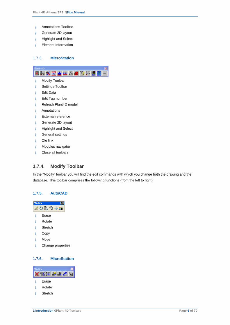
1.7.3. MicroStation
¡ Modify Toolbar
¡ Settings Toolbar
¡ Edit Data
¡ Edit Tag number
¡ Refresh Plant4D model
¡ Annotations
¡ External reference
¡ Generate 2D layout
¡ Highlight and Select
¡ General settings
¡ Ole link
¡ Modules navigator
¡ Close all toolbars
1.7.4. Modify ToolbarIn the “Modify” toolbar you will find the edit commands with which you change both the drawing and the
database. This toolbar comprises the following functions (from the left to right):
1.7.5. AutoCAD
¡ Erase
¡ Rotate
¡ Stretch
¡ Copy
¡ Move
¡ Change properties
1.7.6. MicroStation
¡ Erase
¡ Rotate
¡ Stretch

Plant 4D Athena SP2 ê Pipe Manual
1 Introduction ê Plant-4D Toolbars Page 7 of 70
¡ Copy
¡ Move
¡ Edit equipment
¡ Place Assembly
1.7.7. Settings Toolbar
1.7.8. AutoCAD
This toolbar comprises the following functions (from the left to right):
¡ General Settings dialog
¡ Set Specification
¡ Set Diameter
¡ Set line number (change the name or add new line numbers)
¡ Auto settings (automatically place weldgaps, gaskets or bolts)
¡ Set information level (from 0: no information, to 5: all information)
¡ Takeover pipe settings (takeover diameter, specification or line number of a component)
1.7.9. MicroStation
¡ Set information level (from 0: no information, to 5: all information).
¡ Set specification (selects the active specification from all released specifications in the project).
¡ Set diameter.
¡ Set line number (change the name, delete or add new line numbers).
¡ Auto settings (automatically place weldgaps, gaskets or bolts).
¡ Takeover pipe settings (takeover diameter, specification or line number of a component).
¡ Check for corresponding diameter, line number, specification, etc.
¡ General settings dialog.
¡ Object Information
1.7.10. Component ToolbarsThe “Flanged and Buttwelded” toolbar holds the tools for placing welded and flanged pipeline components.
It can be found in the following location:
AutoCAD Pull down menu >> Plant4D Pipe > Modules >> Buttwelded components
Other component toolbars available from this location are:
Screwed…

Plant 4D Athena SP2 ê Pipe Manual
1 Introduction ê Plant-4D Toolbars Page 8 of 70
Socketweld…
Copper Pipe…
Cast Iron Pipe…
Lined Pipe…
1.7.11. MicroStation
Plant4D Pipe > Modules > Flanged and Buttwelded
Or click from the “Plant-4D Pipe” toolbar the ‘modules’ button to choose other component toolbars.
Modules icon
Available component toolbars from the modules toolbar are:
¡ Flanged and Buttwelded
¡ George Fisher
¡ Water treatment
¡ General components
¡ Equipment
¡ Food
¡ Socketweld
¡ Screwed (Threaded)
¡ Civil
¡ HVAC
¡ Copper
¡ Cast iron
¡ Cabletray

Plant 4D Athena SP2 ê Pipe Manual
1 Introduction ê Plant-4D P&ID Menu Page 9 of 70
¡ Iso
¡ Lined pipe
1.8. Plant-4D P&ID MenuAnother important part of Plant-4D providing several functionalities is the Plant-4D PIPE Menu. It is a
floating dialog, which can be dragged to any location in your environment, containing pulldown menus with
commonly used tools.
Note: If you closed the Plant-4D PIPE Menu abusively, you can’t reopen it easily from the CAD-environment. Restart the drawing and the menu will reappear or enter the following commands on the commandline
AutoCAD
p4d_menubar
Microstation
p4d system picmd menubar
1.9. Add-on ModulesIn this module the particular specifications of Equipment, Steel, George Fischer, HVAC, DIN1185x (Food)
and Water-treatment components can be found. The Plant-4D lock protects components of this add-on
module. Therefore the lock has to obtain an extra code for these components. Contact your Plant-4D
dealer for more information about the extra modules.
1.9.1. AutoCADIn AutoCAD, the add-on module Equipment, Steel, George Fischer and Water can be found in the Plant-
4D Pipe pulldown menu. In the case of Equipment new sub-menus appear. Otherwise toolbars containing
various components will open immediately. These components can then be placed like normal pipe parts.
1.9.2. MicroStationIn MicroStation, the add-on modules can be found in the navigator toolbox or in the pull-down menu Plant-4D Pipe > Modules. From this list all other module lists can be opened.

Plant 4D Athena SP2 ê Pipe Manual
2 Functions of Plant-4D Pipe ê Placement of components Page 10 of 70
2. Functions of Plant-4D Pipe
This chapter describes the functions in Plant-4D Pipe. There is no visible difference in functionality for the
network and standalone environment. Both environments have the same user interface, the only difference
is the database connection.
AutoCAD and MicroStation have the same functionality; the functions of AutoCAD are described in this
chapter. If the MicroStation functions differ considerably from the AutoCAD functions, these will be
described separately.
2.1. Placement of componentsAll components are placed with buttons from the Plant-4D component toolbars. There are two main types
of components.
One has fixed dimensions, which are stored in the specification database
<drive>:\CEA\Projects\Spec.mdb. These are mostly piping components, which are related to standards,
like ANSI or DIN.
The other components are variable components. When placing a variable component, a prompt appears in
the command bar or a dialog box appears on the screen and allows you to specify the required
dimension(s). Once the dimensions are determined, the placing procedure is the same as for the fixed
dimension components. Equipment items are mostly placed as variable components.
Once the component appears on the crosshairs, you can place the component at an XYZ coordinate or
connect it to an existing component. The point at which the component was hanging on your crosshatch
automatically becomes the connection point to existing components.
Some components are asymmetrical and have more then one-connection point.
To change the connection point of the component, click the right mouse button to toggle until the right
connection point appears on your crosshair.
2.2. Placement of pipeline componentsBefore pipeline components can be placed, you have to decide upon some settings. The general settings
dialog box can be found in the Main Toolbar under the function Settings or in the pulldown menu under
Plant-4D PIPE >>Settings >> Plant-4D Pipe (see chapter 0).
First select the desired specification. Then choose the diameter and a line number. Depending upon the
specification, you can also select wall thickness, material, pressure level and a user-definable field. You
can also determine whether automatic gaskets, weldgaps and bolts have to be placed.

Plant 4D Athena SP2 ê Pipe Manual
2 Functions of Plant-4D Pipe ê Placement of pipeline components Page 11 of 70
There are three fields for setting the diameter. The first field describes the main diameter, the second (if
required) the reduced diameter in the main line and the third (if required) the diameter of a branch (i.e. a
reducing tee). The main diameter is always required and all other settings are optional.
The settings remain active until they are changed again. This way you do not have to reintroduce them
before drawing any of their components.
The takeover option is switched on if you want to link the line number from the P&ID module to the Pipe
module. Selecting the line number in the line number box automatically sets the specification and diameter
specified in P&ID.
Make sure the Specification#PIP is spelled correctly in the P&ID module; otherwise the specification
cannot be found in the “Pipe Settings” dialog.
When all settings have been decided upon, select the component you want to place. It will then appear at
your crosshairs. You can now choose the starting point of the component with the right mouse button. In
MicroStation you can use the right mouse button only once to proceed to all linking points. After this it
works as a reset button. If you want to proceed with the beginning of the component, you can use the
button Go to Origin.
Several possibilities for placing a component are shown and explained below:
2.2.1. Continue on an existing componentApproaching an existing component, the connection point will be shown as a node. Click on that node and
your component is placed. You do not have to click on the precise end of the line, as the connecting point
will be found automatically. You only need to indicate the eventual open orientations (i.e. elbows or tees).
By selecting Auto Connect in MicroStation or typing C (Connect) in AutoCAD, you can place your new
component to the connection point of your last placed component. This can speed up the drawing process
when drawing a model from scratch.

Plant 4D Athena SP2 ê Pipe Manual
2 Functions of Plant-4D Pipe ê Placement of pipeline components Page 12 of 70
2.2.2. Place the first component on a lineNow you have the ability to determine the component’s starting point. This can be done by either giving the
coordinates or interactively with your left mouse button.
2.2.3. Relative to an existing componentComponents like elbows, tees and valves can be placed relative to other existing components. The
following example will explain this functionality:
2.2.4. AutoCAD
1. Place an elbow at a certain XYZ location.
2. Select a new elbow and toggle it with the right mouse button to its origin point.
3. Type in the command bar: ‘R’ (relative)
4. Click on the existing elbow.
5. Give the distance (command bar) on which your new elbow is placed, relative to the existing elbow,
and confirm with the left mouse button.
6. Finally, specify in what direction and orientation the new elbow must be set .
2.2.5. MicroStation
1. Place an elbow on a certain XYZ location.
2. Select a new elbow and toggle the elbow in the dialog to its origin (figure).
3. Select Relative in the dialog.
4. Click on the existing elbow.
5. Give a distance on which your new elbow is placed, relative to the existing elbow.
6. Finally, specify in what direction and orientation the new elbow must be set.
Plant 4D Athena SP2 ê Pipe Manual
2 Functions of Plant-4D Pipe ê Placement of pipeline components Page 13 of 70
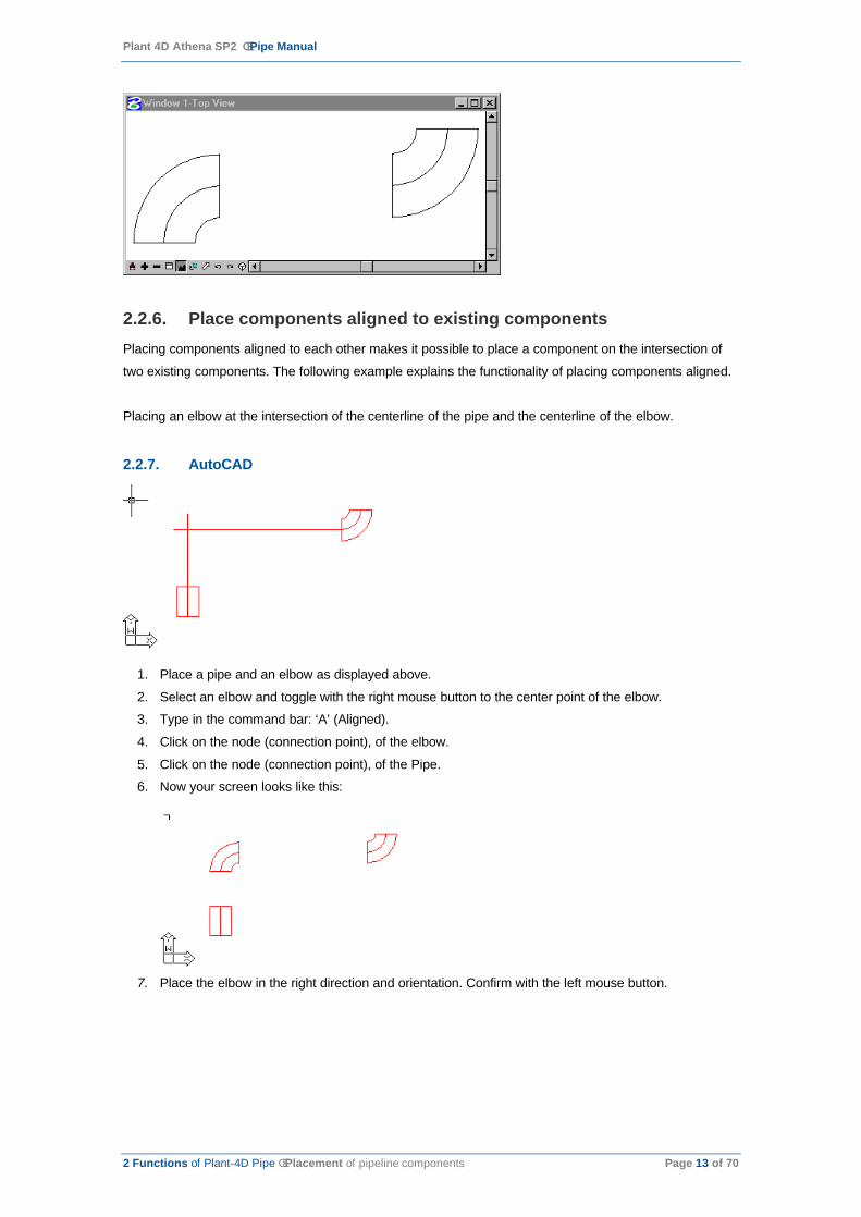
2.2.6. Place components aligned to existing componentsPlacing components aligned to each other makes it possible to place a component on the intersection of
two existing components. The following example explains the functionality of placing components aligned.
Placing an elbow at the intersection of the centerline of the pipe and the centerline of the elbow.
2.2.7. AutoCAD
1. Place a pipe and an elbow as displayed above.
2. Select an elbow and toggle with the right mouse button to the center point of the elbow.
3. Type in the command bar: ‘A’ (Aligned).
4. Click on the node (connection point), of the elbow.
5. Click on the node (connection point), of the Pipe.
6. Now your screen looks like this:
7. Place the elbow in the right direction and orientation. Confirm with the left mouse button.
Plant 4D Athena SP2 ê Pipe Manual
2 Functions of Plant-4D Pipe ê Placement of pipeline components Page 14 of 70
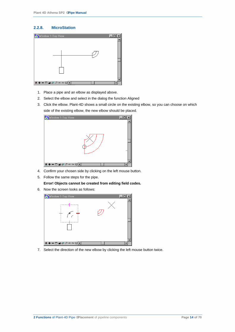
2.2.8. MicroStation
1. Place a pipe and an elbow as displayed above.
2. Select the elbow and select in the dialog the function Aligned
3. Click the elbow. Plant-4D shows a small circle on the existing elbow, so you can choose on which
side of the existing elbow, the new elbow should be placed.
4. Confirm your chosen side by clicking on the left mouse button.
5. Follow the same steps for the pipe.
Error! Objects cannot be created from editing field codes.6. Now the screen looks as follows:
7. Select the direction of the new elbow by clicking the left mouse button twice.

Plant 4D Athena SP2 ê Pipe Manual
2 Functions of Plant-4D Pipe ê Placement of pipeline components Page 15 of 70
8. Finally your screen looks like this:
2.2.9. Route pipe by selecting componentsRoute pipe is a placement routine, which automatically draws pipes between a selection of components
without having to draw a centerline. This shortens the design time and decreases the possibility of
generating a bad connection.
Route pipe by selection will require you to select a number (group) of components (at least 2) between
which you want the pipes or pipe to be drawn. You can select by making a window around the components
or selecting every component separately.
The function will then automatically calculate where a pipe (no other components) can be placed to
complete the distance between two nodes.
2.2.10. Example:
AutoCAD
1. Place the components as displayed above
2. Select the components with a crossing or select the components individually.
3. Select from the pull-down menu: Plant 4D Pipe à Route pipe à By selection à Buttwelded.

Plant 4D Athena SP2 ê Pipe Manual
2 Functions of Plant-4D Pipe ê Placement of pipeline components Page 16 of 70
4. Now your screen looks like this:
MicroStation
1. Place the components as displayed above
2. Select the components with a fence or make an element selection
3. Select from the pull-down menu: Plant 4D Pipe à Pipe routing à By selection à Buttwelded
4. Now your screen looks like this:
2.2.11. Olet placement routineThe Olet placement routine is only applicable for some special components, like:

Plant 4D Athena SP2 ê Pipe Manual
2 Functions of Plant-4D Pipe ê Drawing router lines Page 17 of 70
¡ Weldolet
¡ Threadolet
¡ Sockolet
¡ Stubin
These components are placed in a pipe and have a distance according to a certain reference point.
2.2.12. Placing a ‘weldolet’:
1. Select from the “Buttwelded” toolbar the Weldolet icon.
2. Click on the pipe in which the weldolet should be placed
3. Give a reference point.
4. Select the orientation of the component.
If more than one node is located on this reference point the question ‘Select Component To Connect To’ is
displayed. By selecting a pipe, elbow or tee the distance of the weldolet according to the reference point
can be specified.
2.3. Drawing router linesWith Plant-4D Pipe you have the option to link pipeline components directly to each other or to place them
along router lines. After drawing the centerlines (router lines) of a piping system you can automatically
place elbows and pipes in the system.
2.3.1. AutoCAD
1. Select from the pull-down menu: Plant 4D Pipe à Pipe à Draw 3D routerline à Manually
2. Give the starting point of your router line.
3. In the command bar you can choose how your router line is drawn:
Degrees slope Slope in °Radians slope Slope in radiansPercentages slope Slope in %Fractions slope Slope in fractions (i.e. 1:100=0,01)Absolute vertical Absolute length in Z-directionRelative vertical Relative length in Z-direction
4. Now you can place the router line.
2.3.2. MicroStation
1. Select from the pull-down menu: Plant 4D Pipe à Pipe routing à Place line manually
2. The following dialog appears:
Here you will find the following options:
Distance Absolute

Plant 4D Athena SP2 ê Pipe Manual
2 Functions of Plant-4D Pipe ê User Coordinate System (AutoCAD only) Page 18 of 70
RelativeMeasure Deg. Degrees slope
Rad. Radians slope% Percentages slopeFrac. Fractions slope
Z Distance in Z-level
3. Now you can place the router line.
2.3.3. Continue router lineAfter canceling the Plant-4D manual router line command you are able to continue this router line by
snapping at the end of the existing router line. The following message appears:
When selecting Yes, the existing routerline is connected to the new routerline
2.4. User Coordinate System (AutoCAD only)When connecting a component to an existing one, which requires an orientation, the AutoCAD User
Coordinate System (UCS) is rotated automatically.
The Plant-4D UCS function switches the UCS to the current UCS in the viewport, which is active. Every
orientation can be set in the isometric view. It is no longer necessary to switch between different viewports
to give components certain orientations.
After the component is placed, the current UCS is automatically reset to the world UCS.
2.5. Automatic drawing of router lines With Plant-4D it is possible to automatically generate a router line between two points or components. You
will find the corresponding function in:
2.5.1. AutoCAD Pull-down menu
Plant 4D Pipe >> Draw 3D routerline >> Buttwelded

Plant 4D Athena SP2 ê Pipe Manual
2 Functions of Plant-4D Pipe ê Automatic drawing of router lines Page 19 of 70
2.5.2. MicroStation Pull-down menu
Plant 4D Pipe >> Pipe routing >> Centerline
The menus for the use of router lines are different in both AutoCAD and MicroStation. All following
descriptions refer to the AutoCAD menus. Yet, the procedure is similar in MicroStation. Please note the
following indications:
¡ The first symbol is used for drawing manual router lines.
¡ The second symbol stands for automatic router lines between two points. This symbol (like those for
the following symbols) use different colors: blue for welded, green for screwed and yellow for
socketweld end conditions and red for pulled pipes.
¡ The fifth symbol stands for the function Automatic placement of elbows (colors as described
above).
¡ The sixth symbol stands for the function Automatic placement of pulled pipes.
¡ The seventh symbol stands for Route pipe by routerline.
¡ The eighth symbol stands for Route pipe by selection.
¡ The functions Automatic router lines, and elbows both contain another toolbar, enabling them to
distinguish between the radii. The meaning of the colors is as follows:
yellow 2R
red 3R
green 5R
violet 10R
blue 20R
When using automatic router lines, take the following steps:
1. Choose all the settings for the line to be (i.e. specifications, diameter, line number etc.).
2. Select the corresponding function for drawing automatic router lines: Plant-4D Pipe >> Pipe routing >> Centerline. There are several options available for drawing router lines - Buttwelded, Socketweld and Screwed Pipes. In this function you can select different elbow radii.
3. Choose the starting and ending points of the router line (In MicroStation, the Ortho function has to
be switched off for this). The location of both points may differ in x, y, and z direction.
4. A first possibility is shown highlighted. You can obtain other possibilities by pressing the right mouse
button. (In MicroStation by clicking the Route button).
5. The first and second points are connected to the corners of a box and offer several routes.
6. When you have found the most suitable pipe route, confirm it with your left mouse button. The
routed centerline is then placed. Elbows are automatically placed at the beginning and end of the
router line if needed.
7. Select from the Plant-4D PIPE pulldown menu: Pipe routing >> Elbows. Here you can also
choose between different possibilities via end conditions and radii. Once the required selection has
been made click on the previously placed router line with your left mouse button and the connection
is made.
8. The program will test whether the elbow will fit on the router line.
9. At this point in time you can still place other components (i.e. valves, reducers etc.) on the routed
centerline, if necessary.

Plant 4D Athena SP2 ê Pipe Manual
2 Functions of Plant-4D Pipe ê Using Tags Page 20 of 70
10. Now open Route pipe >> By router line from the Plant-4D PIPE pulldown menu and select the
desired end condition from here. The select the pre-routed centerline. You have to confirm your
choice with the right mouse button (In MicroStation with the left mouse button). The elbows (and
components) are now connected with pipelines.
2.6. Using TagsPlant-4D identifies components based on their tags. Besides identification Tags also feature linking
components across drawings and environments (2D/3D). Therefore the “Tag” dialog is an often seen
dialog in Plant-4D.
2.6.1. Tag structure and CustomizationA tag can consist of up to 6 fields (tag parts). The structure of the tag is defined per component type in the
settings table. The number and type of fields of this dialog may vary between several types of components.
This defines:
¡ The number of fields/parts for this tag;
¡ The type of data for each tag-part (numerical or textual);
¡ The dividing characters/symbols between those parts;
¡ Whether the field is a selectable or just a field to fill in.
Note: How to change such settings is beyond the scope of this document. Please refer to the Customization Manual for more detailed information about this subject.
2.6.2. Listed tag parts
When a list is provide at a field you can recognize it at the button at the left hand side of a field.
Clicking on it will show the list of available entries. This list can be seeded by a list of fixed values or even
from a table somewhere in the project database.
Plant 4D Athena SP2 ê Pipe Manual
2 Functions of Plant-4D Pipe ê Using Tags Page 21 of 70
2.6.3. Linking componentsWhenever an entered tag is already in use, Plant-4D will automatically prompt you:
When you decide to create a link between components they will share their Solo- and CommonData. Any
change will automatically applied on all the related components to. Actually a component sharing a tag
number is interpreted as one entity with several graphical representations by Plant-4D.
Note: Once components are linked together by a sharing a tag number, you can easily divide them. To make sure what you are doing when linking components to each other.
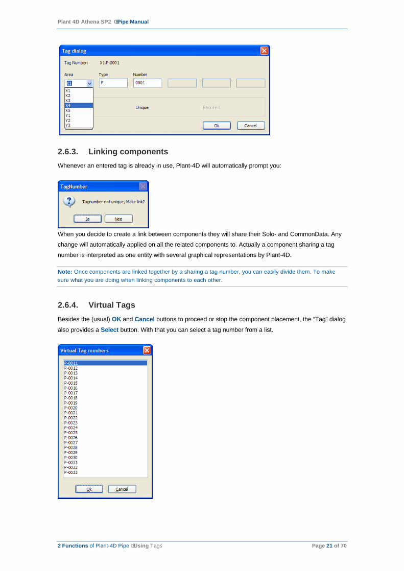
2.6.4. Virtual TagsBesides the (usual) OK and Cancel buttons to proceed or stop the component placement, the “Tag” dialog
also provides a Select button. With that you can select a tag number from a list.
Plant 4D Athena SP2 ê Pipe Manual
2 Functions of Plant-4D Pipe ê Plant-4D Parent-child link Page 22 of 70
This list contains an overview of so called ‘Virtual Tag numbers’ corresponding with the type of component
you are currently placing. Virtual tags are tags declared in advance without a representation in any
drawing. Those are usually used to declare tags and add data to it, so it can be later placed in a drawing
without needing to add all of the data to it. (For more detailed information about Virtual Tags see the 4D-
Explorer User Guide.)
When you select a tag from this list and select OK, the selected tag will be copied to the “Tag” dialog.
Because the tag already exists from to the opinion of Plant-4D (even though it hasn’t drawn yet) you will be
prompted whether you want to make a link when proceeding with the tag.
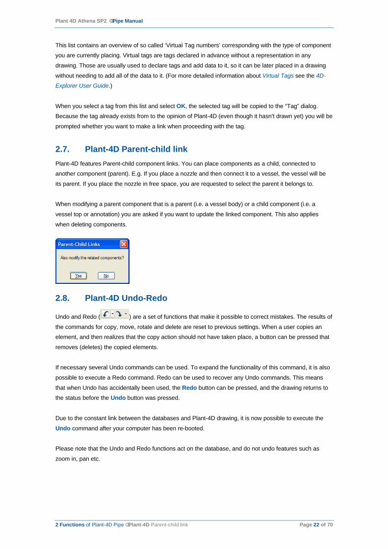
2.7. Plant-4D Parent-child linkPlant-4D features Parent-child component links. You can place components as a child, connected to
another component (parent). E.g. If you place a nozzle and then connect it to a vessel, the vessel will be
its parent. If you place the nozzle in free space, you are requested to select the parent it belongs to.
When modifying a parent component that is a parent (i.e. a vessel body) or a child component (i.e. a
vessel top or annotation) you are asked if you want to update the linked component. This also applies
when deleting components.
2.8. Plant-4D Undo-Redo
Undo and Redo ( ) are a set of functions that make it possible to correct mistakes. The results of
the commands for copy, move, rotate and delete are reset to previous settings. When a user copies an
element, and then realizes that the copy action should not have taken place, a button can be pressed that
removes (deletes) the copied elements.
If necessary several Undo commands can be used. To expand the functionality of this command, it is also
possible to execute a Redo command. Redo can be used to recover any Undo commands. This means
that when Undo has accidentally been used, the Redo button can be pressed, and the drawing returns to
the status before the Undo button was pressed.
Due to the constant link between the databases and Plant-4D drawing, it is now possible to execute the
Undo command after your computer has been re-booted.
Please note that the Undo and Redo functions act on the database, and do not undo features such as
zoom in, pan etc.

Plant 4D Athena SP2 ê Pipe Manual
3 Additional Plant-4D Functions ê Tools Page 23 of 70
3. Additional Plant-4D Functions
Additional Plant-4D functions can be found in the toolbar Plant-4D PIPE Menu. The miscellaneous
functions in the Plant-4D plugin toolbar are exactly similar for AutoCAD and Microstation. Button handling,
appearance and execution of the functions do not differ in the two supported CAD platforms.
The miscellaneous functions are executed from the Tools pulldown menu. In addition, HTML Help pages
for each function are available under the Help pulldown.
3.1. ToolsWith this option you can open a toolbar containing all the Plugin tools. Using those functions from the
toolbar can speed up your design process when needing those functions frequently.
3.2. Centerline FunctionWith the manual router line function, described in chapter 0, the router lines are drawn by typing values in
the command bar and by giving the direction of the router line graphically in the screen.
A new router line function complete with a user interface has the same functionality as the manual router
line function. The only difference is that the input is specified in a dialog box instead of the command bar.
The first tab sheet, the start point, contains the following items:
¡ Line number: In this box the current line number is displayed. Router lines drawn are attached to
this line number.

Plant 4D Athena SP2 ê Pipe Manual
3 Additional Plant-4D Functions ê Centerline Function Page 24 of 70
¡ Specification: The current specification is displayed in the box.
¡ Main Diameter: The current diameter is displayed in this box.
¡ Insulation: The insulation of the pipe can be specified in this edit box.
¡ Depth: With the place line function, it is possible to place router lines with respect to top, bottom or
center of pipe. Placing a router line based on top or bottom of pipe causes the router line to be
drawn with an offset. This offset is the radius of the pipe increased by the insulation thickness.
¡ Start: Click on the start button to start the routing.
¡ Relative: Relative placement of router lines can be done with respect to:
Existing router lines
Existing components
Relative placement according to existing router lines enables the user to start new router lines on an offset.
Relative placement according to existing components enables the user to start new router lines on the
available nodes of the component. By clicking ‘next node’ the starting point of the router line is toggled
through the nodes of the component.
Coordinate input: The coordinate input box displays the absolute coordinate according to the
MicroStation or AutoCAD origin. By pressing the ‘Shift_+’ combination relative placement is
made possible in the directions specified.
The second tab sheet, End Point, contains the following items:
Plane
In this this section the direction of the router line can be determined:
¡ North
¡ South
¡ West
¡ East
¡ Up
¡ Down
All directions are according to the current UCS.
Free
The Free option enables the user to draw a router line with no predefined direction.
Box

Plant 4D Athena SP2 ê Pipe Manual
3 Additional Plant-4D Functions ê Componentbuilder Page 25 of 70
The box option enables the user to specify a starting and end point through which a router line is drawn. By clicking ‘Next Route’ the user can choose which plane or diagonal the router line is drawn.
The end point of the box can be specified by clicking in the X,Y,Z boxes and by holding the ‘Shift_+’
buttons to specify a distance.
Slope
Sloping router lines can be drawn by specifying the following types of slope:
¡ Degree slope
¡ Percentage slope
¡ Radian slope
Undo
The undo button erases the last drawn router line.
3.3. ComponentbuilderThe ComponentBuilder tool can be used to view the (graphical) definition the component/symbol or even
modify these definitions.
The Component Builder presents the definition in a tree format, corresponding with the logical (data)
structure of components:
¡ The top level node present the ‘component name’ as it is recognized by Plant-4D, referred to in
specifications and stored in the components database.
¡ At the level beneath the top level you will find all the ‘primitives’ a component/symbol consists of. The
name of this node refers to the type of the primitive.
Note: Because Plant-4D is a CAD-system independent system and defines components only once for both AutoCAD and Microstation, components are reduced to drawing primitives (such as lines, circles, arcs, rectangles) and stored as such into the component database. The CAD system will handle those definitions on its own system specific way.
¡ Every primitive consists of a collection of parameters, which are provided in the tree-level beneath a
primitive.

Plant 4D Athena SP2 ê Pipe Manual
3 Additional Plant-4D Functions ê Elbolet Function Page 26 of 70
To modify a parameter select it from the tree and click the Edit button . The following dialog will
appear.
Note: Parameters for primitive can not only be static values, but also contain calculations or even contain parameterized fields. For instance, you color-parameter could be refer to a column of its SoloData or even be dictated by a column of the related specification.
The shown Formula Editor presents you some algebraic and goniometric functions and a presents you a
list of fields from Specifications (Spec), CommonData (Comm) and SoloData (Solo). With this FormulaEditor you can build the necessary expression defining this parameter. Press OK when finished. The
changes will be applied to this field. However it isn’t stored yet in the database. You have to confirm those
changes by click in the Save button .
Note: Remember to save your changes before you close the Component Builder. It will not prompt you when closing with unsaved changes!
When you want to view another component in the Component Builder you can use the Select button .
For more detailed information over the structure of components, featured parameters and how to maintain
them, refer to the Component Builder Manual and Customization Manual.
Note: Be aware of the fact that changing existing symbols not only affects the current drawing, but every drawing in every project using this component library.
3.4. Elbolet FunctionBefore placing an ‘elbolet’, make sure correct pipe settings like Specification, Diameter and Line numberare set. In case of non-matching pipe settings Plant-4D will prompt a message to takeover or ignore the
pipe settings of the elbow.
The elbolet placement is started from the Plant-4D Pipe Menu toolbar Tools. After activating the elbolet
function the system prompts the user to select an elbow.
Plant 4D Athena SP2 ê Pipe Manual
3 Additional Plant-4D Functions ê Elbolet Function Page 27 of 70
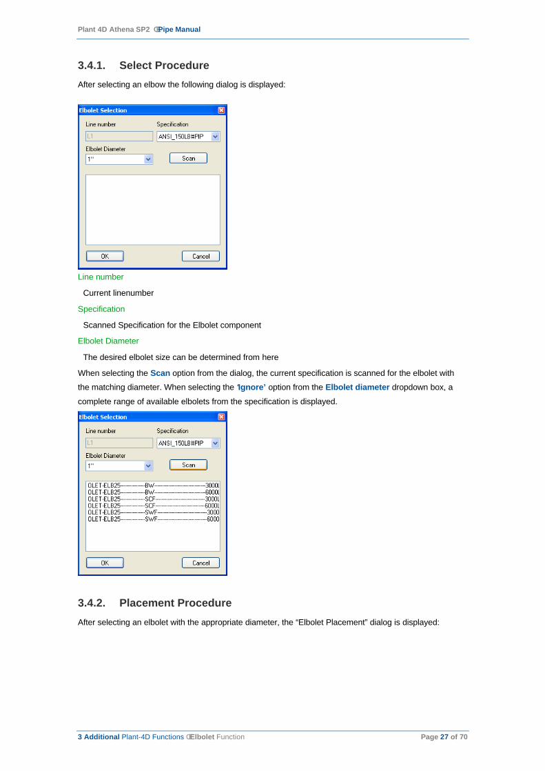
3.4.1. Select ProcedureAfter selecting an elbow the following dialog is displayed:
Line number
Current linenumber
Specification
Scanned Specification for the Elbolet component
Elbolet Diameter
The desired elbolet size can be determined from here
When selecting the Scan option from the dialog, the current specification is scanned for the elbolet with
the matching diameter. When selecting the ‘Ignore’ option from the Elbolet diameter dropdown box, a
complete range of available elbolets from the specification is displayed.
3.4.2. Placement ProcedureAfter selecting an elbolet with the appropriate diameter, the “Elbolet Placement” dialog is displayed:

Plant 4D Athena SP2 ê Pipe Manual
3 Additional Plant-4D Functions ê Elbolet Function Page 28 of 70
When the “Placement method” dialog is displayed, a ghost image of the elbolet is automatically attached to
the Elbow in the model. This is a temporary image, which is replaced by the elbolet component when the
final placement method of the elbolet is determined.

Plant 4D Athena SP2 ê Pipe Manual
3 Additional Plant-4D Functions ê Elbolet Function Page 29 of 70
3.4.3. Placement Methods
3.4.4. Standard
The standard placement method places the elbolet on the edge of the selected elbow. By selecting the
Angle option, the rotating angle can be defined in the Angle box.
Straight Angular
Plant 4D Athena SP2 ê Pipe Manual
3 Additional Plant-4D Functions ê Elbolet Function Page 30 of 70
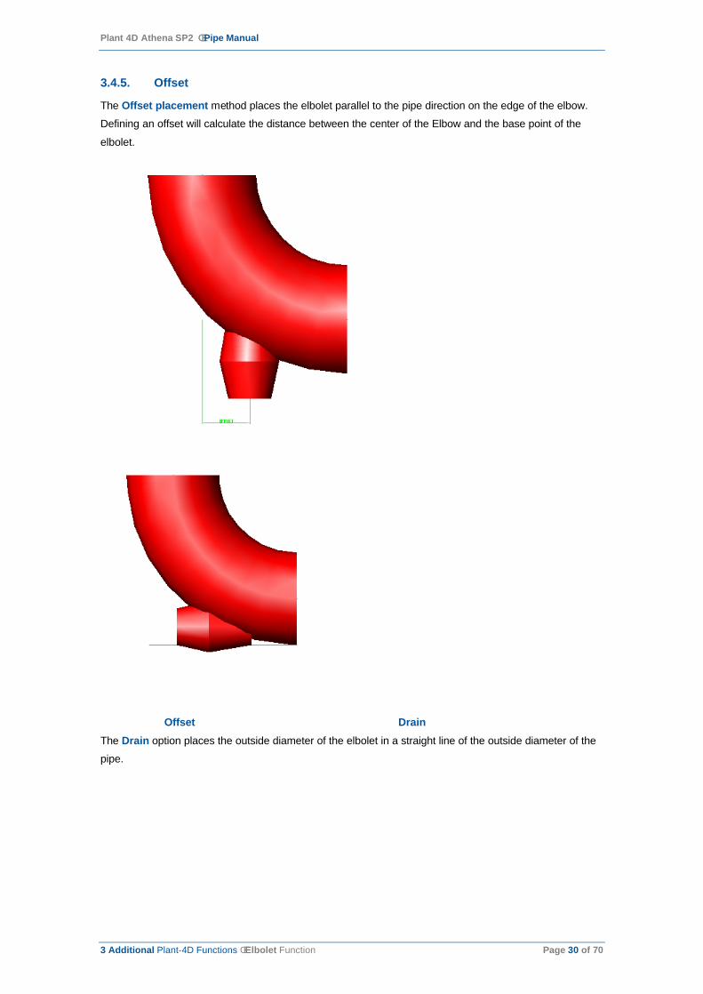
3.4.5. Offset
The Offset placement method places the elbolet parallel to the pipe direction on the edge of the elbow.
Defining an offset will calculate the distance between the center of the Elbow and the base point of the
elbolet.
Offset DrainThe Drain option places the outside diameter of the elbolet in a straight line of the outside diameter of the
pipe.

Plant 4D Athena SP2 ê Pipe Manual
3 Additional Plant-4D Functions ê Elbolet Function Page 31 of 70
3.4.6. Perpendicular
The Perpendicular placement method places the elbolet perpendicular to the edge of the elbow.
Perpendicular Radial AngleThe Radial Angle option rotates the elbolet along the outside of the elbow.

Plant 4D Athena SP2 ê Pipe Manual
3 Additional Plant-4D Functions ê Elbolet Function Page 32 of 70
3.4.7. Custom
The Custom placement method places the elbolet in a user-defined XYZ startpoint and direction. The
Custom placement method is in combination with the Angle and Point option.
The angle defines the start point of the elbolet, perpendicular to the end of the elbow.
The direction of the elbolet can be determined by a XYZ input from the dialog, or by selecting the Point
option. By using the point option the direction of the elbolet can be determined graphically.
Startpoint Angle… Direction Angle…
The Toggle button switches the ghost image of the elbolet to the other side of the outer edge of the elbow.
The Place button replaces the ghost image of the elbolet with the elbolet component and completes the
placement procedure.
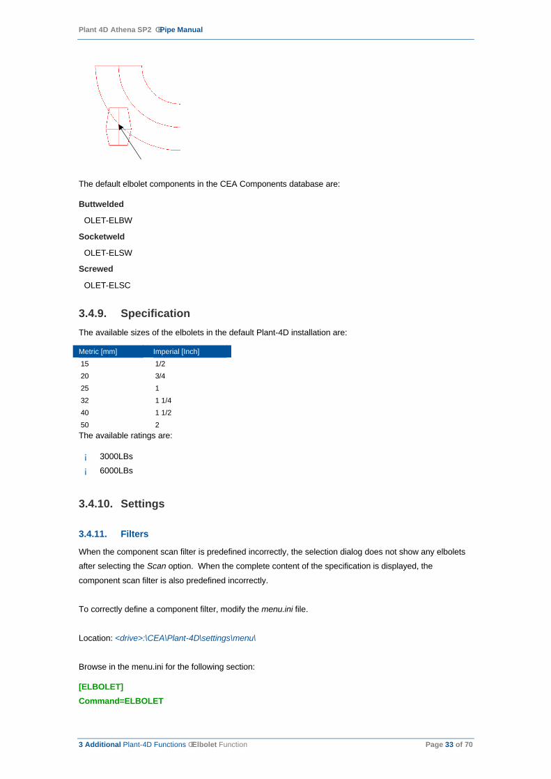
3.4.8. Elbolet ComponentThe start point and direction of the elbolet are calculated according to the outer edge of the Elbow. The
base point of the elbolet is placed on this edge.
Plant 4D Athena SP2 ê Pipe Manual
3 Additional Plant-4D Functions ê Elbolet Function Page 33 of 70
The default elbolet components in the CEA Components database are:
Buttwelded
OLET-ELBW
Socketweld
OLET-ELSW
Screwed
OLET-ELSC
3.4.9. SpecificationThe available sizes of the elbolets in the default Plant-4D installation are:
Metric [mm] Imperial [Inch]
15 1/2
20 3/4
25 1
32 1 1/4
40 1 1/2
50 2The available ratings are:
¡ 3000LBs
¡ 6000LBs
3.4.10. Settings
3.4.11. Filters
When the component scan filter is predefined incorrectly, the selection dialog does not show any elbolets
after selecting the Scan option. When the complete content of the specification is displayed, the
component scan filter is also predefined incorrectly.
To correctly define a component filter, modify the menu.ini file.
Location: <drive>:\CEA\Plant-4D\settings\menu\
Browse in the menu.ini for the following section:
[ELBOLET]Command=ELBOLET

Plant 4D Athena SP2 ê Pipe Manual
3 Additional Plant-4D Functions ê About the PIPE Menu Page 34 of 70
Arguments=CF=OLET-ELB*Name=Elboleticon=elbolet.bmp
Arguments=CF is defined as a filter on the Componentindex field of the current specification.
In this example all components from the specification starting with OLET-ELB are displayed in the
selection dialog.
More filters that can be defined in the menu.ini are:
Argument Example Description
CDL 123 CommonDataLink to use (LineNumber). The active LineNumber is changed.
CF OLET-ELB* Componentindex Filter.
G OLETFF Component Group name.
D 20 Predefined diameter for elbolet.
VL 1 (on) or 0 (off) Extra edit fields, the value is stored in the Solo.Dim2 field (Optional).
3.4.12. Size
The size of the ghostimage of the elbolet is stored in the project settings table. To modify the size of the
ghost image, open the settings form from the Plant-4D Datamanager: Root[PIP]à Section[Elbolet]
3.5. About the PIPE MenuThe Plant-4D PIPE Menu is loaded automatically in the PIPE application. If the menu bar is not loaded or
is closed, the toolbar is activated with the following command:
AutoCAD
p4d_menubar
Microstation
p4d system picmd menubar
3.6. UCS Box FunctionsThe UCS dialog box appears on the screen to determine the orientation in which a component will be
placed.
The Plant-4D UCS dialog box contains the following options:
UCS Rotate
In the UCS rotate edit box the angle of orientation of a component can be specified. Typing an angle automatically rotates the current UCS.

Plant 4D Athena SP2 ê Pipe Manual
4 Example of a Plant-4D Pipe Drawing ê UCS Box Functions Page 35 of 70
Distance
In the distance edit box the length of pipes can be specified.
Angle
This is the current orientation angle in which the component is pointing. (non editable).
On
The on checkbox disables or enables the UCS icon on the screen.Floating Switching on the Floating checkbox moves the UCS icon from its origin, bottom left of the screen, to the component which requires an orientation.
Follow
The follow option changes the view direction of the active viewport to the component orientation possibilities.
Views
The Plant-4D UCS dialog box enables you to change the view perspective of the active viewport during a placement function.
Components, which have a vertical direction, i.e. Vessels, can be placed vertically by selecting i.e. the
Front view. Clicking on a view icon, the UCS icon automatically rotates and the direction of components
can be determined in the new current UCS.
4. Example of a Plant-4D Pipe Drawing
In this chapter we will setup an example drawing:
Start a new drawing.
First you have to establish the settings. For this choose from the “Settings” toolbar the General settings
button
Or to start it from the pulldown menu:
AutoCAD: Plant-4D Pipe >> Settings >> Plant-4D PipeMicroStation: Plant-4D Pipe >> Plant-4D >> Settings GeneralThe following window appears on your screen:
Plant 4D Athena SP2 ê Pipe Manual
4 Example of a Plant-4D Pipe Drawing ê UCS Box Functions Page 36 of 70
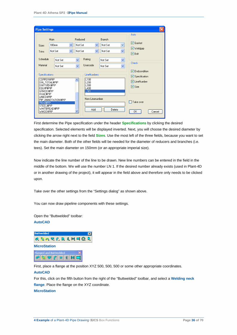
First determine the Pipe specification under the header Specifications by clicking the desired
specification. Selected elements will be displayed inverted. Next, you will choose the desired diameter by
clicking the arrow right next to the field Sizes. Use the most left of the three fields, because you want to set
the main diameter. Both of the other fields will be needed for the diameter of reducers and branches (i.e.
tees). Set the main diameter on 150mm (or an appropriate imperial size).
Now indicate the line number of the line to be drawn. New line numbers can be entered in the field in the
middle of the bottom. We will use the number LN 1. If the desired number already exists (used in Plant-4D
or in another drawing of the project), it will appear in the field above and therefore only needs to be clicked
upon.
Take over the other settings from the “Settings dialog” as shown above.
You can now draw pipeline components with these settings.
Open the “Buttwelded” toolbar:
AutoCAD
MicroStation
First, place a flange at the position XYZ 500, 500, 500 or some other appropriate coordinates.
AutoCADFor this, click on the fifth button from the right of the “Buttwelded” toolbar, and select a Welding neckflange. Place the flange on the XYZ coordinate.
MicroStation
Plant 4D Athena SP2 ê Pipe Manual
4 Example of a Plant-4D Pipe Drawing ê UCS Box Functions Page 37 of 70
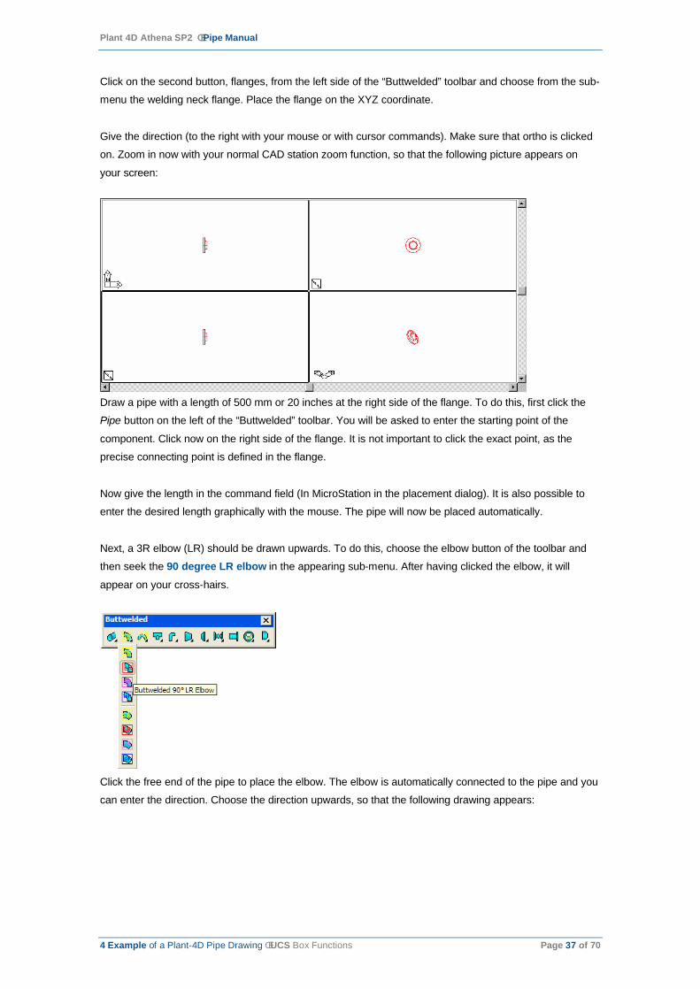
Click on the second button, flanges, from the left side of the “Buttwelded” toolbar and choose from the sub-
menu the welding neck flange. Place the flange on the XYZ coordinate.
Give the direction (to the right with your mouse or with cursor commands). Make sure that ortho is clicked
on. Zoom in now with your normal CAD station zoom function, so that the following picture appears on
your screen:
Draw a pipe with a length of 500 mm or 20 inches at the right side of the flange. To do this, first click the
Pipe button on the left of the “Buttwelded” toolbar. You will be asked to enter the starting point of the
component. Click now on the right side of the flange. It is not important to click the exact point, as the
precise connecting point is defined in the flange.
Now give the length in the command field (In MicroStation in the placement dialog). It is also possible to
enter the desired length graphically with the mouse. The pipe will now be placed automatically.
Next, a 3R elbow (LR) should be drawn upwards. To do this, choose the elbow button of the toolbar and
then seek the 90 degree LR elbow in the appearing sub-menu. After having clicked the elbow, it will
appear on your cross-hairs.
Click the free end of the pipe to place the elbow. The elbow is automatically connected to the pipe and you
can enter the direction. Choose the direction upwards, so that the following drawing appears:

Plant 4D Athena SP2 ê Pipe Manual
4 Example of a Plant-4D Pipe Drawing ê UCS Box Functions Page 38 of 70
Draw another flange at the end. Toggle the flange by using your right mouse button to the buttwelded side.
By giving the ‘C’ (Connect) command the flange is automatically connected to the elbow.
Place a ball valve and another flange on the line, so that you get the following construction:
Zooming in on the ball valve and flange, you will see that gaskets are automatically placed (see settings).
This is only when you use the PN10#PIP specification.
Select another 90 degree LR elbow from the “Buttwelded” toolbar and place the new elbow 500 mm or 20
in relative to the last placed welding neck flange in the positive X-direction. Then, place a tee of 400 mm or
16 in relative to the last placed elbow. Toggle the tee to its center point. The branch side should point in
the negative Y-direction.
Your screen should look like the next picture:

Plant 4D Athena SP2 ê Pipe Manual
4 Example of a Plant-4D Pipe Drawing ê UCS Box Functions Page 39 of 70
AutoCADSelect the three components, Flange, Elbow and Tee which you want to connect through a pipe by a
crossing or select the three components individually
MicroStation
Select the three components, Flange, Elbow and Tee by using a fence or an element selection.
Now select from the pull-down menu the Plant 4D Pipe >> Route Pipe >> By selection >> Buttweldedfunctionality.
When you ‘hide’ your piping model, your screen looks like this:
This example shows the way to connect components without router lines.
Now we want to create a second connecting point in the space left and automatically generate router lines
and pipes.
Draw a tee at the position 4000 (160), 3000 (120), 4000 (160). For this, choose the point of crossing as
starting point and the direction so that it is displayed as follows:

Plant 4D Athena SP2 ê Pipe Manual
4 Example of a Plant-4D Pipe Drawing ê UCS Box Functions Page 40 of 70
AutoCAD
Select from the pull-down menu: Plant 4D Pipe >> Draw 3D routerline >> Buttwelded >> 3R.
You will be asked for the starting point. Indicate the end of the first tee. The second point is the end of the
last placed tee in space. The easiest way is to snap to the connection points (nodes) of the components.
Now you see a box appear between the two components. By clicking on the right mouse button you can
toggle to the recommended pipe route.
Confirm your pipe route by clicking on the left mouse button. The elbows at the connecting points are set
automatically when needed.
Now choose Plant 4D Pipe >> Route elbows >> Buttwelded >> 3R and click on the router line. The
program searches for all the places on the line where elbows should be brought in and automatically
inserts these. You will then get the following model:

Plant 4D Athena SP2 ê Pipe Manual
4 Example of a Plant-4D Pipe Drawing ê UCS Box Functions Page 41 of 70
Now choose Plant 4D Pipe >> Route pipe >> By routerline >> Buttwelded and click the router line. The
pipes are automatically placed and you will get the following model:
MicroStationSelect from the pull-down menu: Plant 4D Pipe >> Pipe routing >> Centerline >> LR Elbows.
You will be asked for the starting point. Indicate the end of the first tee. The second point is the end of the
last placed tee in space. The easiest way is to snap to the connection points (nodes) of the components.
Now you will see a box appear between the two components.

Plant 4D Athena SP2 ê Pipe Manual
4 Example of a Plant-4D Pipe Drawing ê Information Level Page 42 of 70
By clicking on Next Route you can toggle to the recommended pipe route.
Confirm your pipe route by clicking on the left mouse button. The elbows at the connecting points are set
automatically when needed.
Now choose Plant 4D Pipe >> Pipe routing >> Elbows >> 3R and click on the router line. The program
searches for all the places on the line where elbows should be brought in and automatically inserts these.
Now choose Plant 4D Pipe >> Pipe routing >> By routerline >> Buttwelded and click the router line.
The pipes are automatically placed and you will get the following model:
4.1. Information LevelThe information level is used to define the amount of information you want to provide the database with.
There are six options: level 0 to level 5. Level 0 means that no dialogs are displayed when new
components are placed. Data cannot be edited working in this level. When the information level is set to a
value other than 0, two dialogs will be displayed, namely the Tag number dialog and the Common-
/SoloData dialog.
The display of dialogs depends on the information level and the kind of tag. They are only shown when
placing valves, tanks, pumps etc.
The range of valid levels can be defined in the project settings using the 4D-Explorer.
Plant 4D Athena SP2 ê Pipe Manual
4 Example of a Plant-4D Pipe Drawing ê The Tag number dialog Page 43 of 70
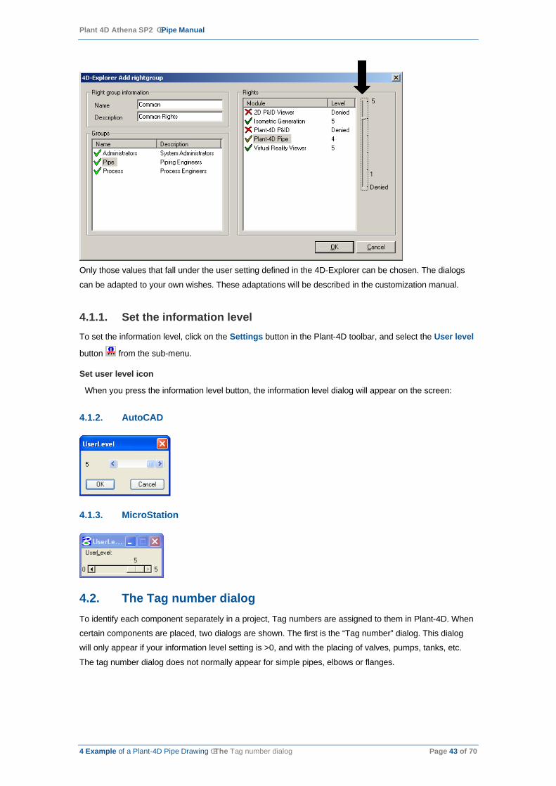
Only those values that fall under the user setting defined in the 4D-Explorer can be chosen. The dialogs
can be adapted to your own wishes. These adaptations will be described in the customization manual.
4.1.1. Set the information level To set the information level, click on the Settings button in the Plant-4D toolbar, and select the User level
button from the sub-menu.
Set user level icon
When you press the information level button, the information level dialog will appear on the screen:
4.1.2. AutoCAD
4.1.3. MicroStation
4.2. The Tag number dialogTo identify each component separately in a project, Tag numbers are assigned to them in Plant-4D. When
certain components are placed, two dialogs are shown. The first is the “Tag number” dialog. This dialog
will only appear if your information level setting is >0, and with the placing of valves, pumps, tanks, etc.
The tag number dialog does not normally appear for simple pipes, elbows or flanges.

Plant 4D Athena SP2 ê Pipe Manual
4 Example of a Plant-4D Pipe Drawing ê The Tag number dialog Page 44 of 70
When you select a tag from this list and select OK, the selected tag will be copied to the “Tag” dialog.
Because the tag already exists from to the opinion of Plant-4D (even though it hasn’t drawn yet) you will be
prompted whether you want to make a link when proceeding with the tag.
When the Tag number is entered and the OK button pressed, Plant-4D will check if the entered number
has already been used. Since a Tag number is unique throughout the entire project, no double Tag
numbers can be used. If the Tag number has been used previously, Plant-4D will respond with the
following dialog:
This means that you have entered the same Tag number twice in the project. This can be useful when, for
example, you use the same component in various drawings. In that case, you should press the OK button.
Plant-4D will now link the new component to the same Common- and Solo Data. This way, both
components have the same data.
It is also desirable to link data of the 3D pipe component to the P&ID component. By pressing the OKbutton the data from the P&ID component is linked to the 3D component by the tag number.
If you want to create a new component with a new tagnumber, press the Edit button. Plant-4D returns to
the edit Tag number dialog where you can enter a new Tag. The next free number is automatically put
forward.
Note: If the Tag number dialog does not appear after you have placed a component, the Information level is set to zero.
4.2.1. Edit Tag numberExisting Tag numbers can be edited with the Edit Tag number Error! Objects cannot be created from editing field codes. function.
If you choose this function, you can select the component you want to edit and get the same functionality
as described in the text above.
Warning: If you want to change a Tag number into an already existing number and you give a positive answer to the question for a corresponding link, Plant-4D will overwrite the component data with the data of the already existing component. The data of the chosen component will then irrefutably be gone.

Plant 4D Athena SP2 ê Pipe Manual
4 Example of a Plant-4D Pipe Drawing ê Data Dialog Page 45 of 70
4.3. Data DialogData is of the utmost importance in a piping design program. With Plant-4D, a wide range of options are
offered to use valuable data in your project. Each project requires its own data and data-structure. Plant-
4D Data Dialog functions for Common and Solo Data provide you with this functionality.
4.3.1. Common and Solo DataCommon Data is process information that is the same for a group of components and Process lines. When
you place a pipe, you assign for instance a line number, diameter, specification and a commodity. When
you place a valve in this line, some data fields of the valve correspond with those of the line. In Plant-4D
we do not copy the data from the Process line into the component to avoid data inconsistency if either one
is changed. In Plant-4D, every tag has a set of Solo Data and a link to the Common Data. Various
components can refer to one set of Common Data. In the case described above, the line as well as the
valve would have the same Common Data link, thus having a link to the same Common Data record.
Solo Data is assigned to and unique for each component. With Solo Data, Plant-4D also creates a Solo
Data record and stores a link to this record in the component.
Common and Solo Data can be used as additional information for reporting and annotating purposes.
4.3.2. Edit Common and Solo DataCommon and Solo Data can be edited during the placing of a component or at any time afterwards. This
can be done under the condition that your current information level is set to a value >0. The Common and
Solo Data dialog is the second dialog that is displayed when a component is placed.
If you want to edit the data when the component has already been placed, click on the Edit Data button
in the Main Toolbar:

Plant 4D Athena SP2 ê Pipe Manual
4 Example of a Plant-4D Pipe Drawing ê Change Properties Page 46 of 70
The dialog box displayed above is a “Valve” dialog. The contents of this dialog can be edited by placing a
cursor in the field you want to edit. The contents are stored in the project database after you have pressed
the OK button. If any field in the dialog is grayed-out, the current information level setting is not sufficient
to edit that particular field.
All fields, tab sheets and layout preferences are completely user definable. To modify the dialog boxes see
the Customization Manual.
4.4. Change PropertiesIt may occur that the draftsman has drawn components, lines or primitives with the wrong kind of line or on
the wrong level. Instead of erasing and redrawing all the components, Plant-4D gives you the ability to
change selected settings for the components already drawn. This function is called Change Propertiesand can be found in the “Modify” toolbar.
With the Change Properties command the following items can be changed: Level/Layer, Color, Line type
and Line width.
4.4.1. AutoCAD…
Click the button and select the components you want to change. Confirm the components by means of the
right mouse button. You will then get the following window in which you can change the settings for the
components and confirm with OK.
4.4.2. MicroStation
This function works slightly different. Instead of a special dialog, we can use standard MicroStation
functionality to change the settings. First, select all the items you want to change. You can then change
the desired settings with the standard Primary Tools toolbar. MicroStation will execute the changes
immediately. To write these changed settings to the database, choose the Change Properties button from
the “Plant-4D” toolbar.

Plant 4D Athena SP2 ê Pipe Manual
4 Example of a Plant-4D Pipe Drawing ê Plant-4D Refresh Page 47 of 70
4.5. Plant-4D RefreshWith this function, the current drawing is regenerated from the database. All changes to the database
made by you and other users will be reflected in the drawing. To force a regeneration, click the Refresh
icon from the “Plant-4D” toolbar.
4.6. Reference DrawingsThere are two kinds of drawings that can be referenced in Plant-4D: standard AutoCAD/MicroStation
drawings and Plant-4D drawings
4.6.1. AutoCAD
You can reference an AutoCAD drawings through the command Reference AutoCAD drawing that can
be found in the menu under Plant-4D Pipe >> Reference drawing >> AutoCAD. You will then be
prompted for the path and drawing name of the AutoCAD drawing. Indicate a drawing and determine the
insertion point, scaling and direction of the drawing to be referenced in the current drawing.
4.6.2. MicroStation
You can use the standard MicroStation command to reference drawings File >> Reference or Tools >>Attach.
You can also reference Plant-4D drawings from the current project. To use this function pull down the
menu item in AutoCAD, or in MicroStation click on the X-Ref button from the “Plant-4D” toolbar.
You will get the following dialog:
On the left hand side you will see all PIPE drawings available in the project.
Choose the drawing you want to refer to and click the button. The drawings that are referenced appear
on the right side. Click on the Redraw button to load the drawing from the database. Drawings are by
default inserted at 0,0,0 but can be inserted at other coordinates by using the Edit button on the
Reference Plant-4D Drawings. In addition, you can manage which layers of the referenced Plant-4D
drawing should be visible.

Plant 4D Athena SP2 ê Pipe Manual
4 Example of a Plant-4D Pipe Drawing ê Modify Commands Page 48 of 70
4.6.3. AutoCAD
4.6.4. MicroStation
4.7. Modify CommandsAs seen before Plant-4D adds intelligence to components. So a Plant-4D drawing isn’t just a plain drawing
like AutoCAD or Microstation creates but is based on a database oriented concept. Every component has
data-equivalents in the project database. Due to this ‘intelligence’ and relationships in data, the usual
modify commands like move, copy, rotate, etc. might require multiple steps to maintain the integrity of your
model.
Therefore Plant-4D provides its own modify functions. It is also allowed to use the standard AutoCAD or
MicroStation modify functions: those are redirected to the special Plant-4D behaviour if necessary.
4.7.1. AutoCAD
4.7.2. MicroStation

Plant 4D Athena SP2 ê Pipe Manual
4 Example of a Plant-4D Pipe Drawing ê Modify Commands Page 49 of 70
4.7.3. ErasePlant-4D’s Erase is located in the Modify menu of the “Plant-4D” toolbar. This command works in the
same manner as the native CAD command. Choose Erase (AutoCAD: , Microstation: ) and select
the items to be deleted. The selected items are deleted from the drawing and the project database.
4.7.4. RotateWith the rotate command it is possible to rotate components or component groups around a single datum
point. Choose the function Rotate
(AutoCAD: , Microstation: ) and select the component(s). Specify the point around which to rotate
the selection, and indicate the new direction with the cursor. When you work with component groups, then
use the fence/window function.
4.7.5. Stretch
With this command you can move components or modify line lengths. Select the Stretch (AutoCAD: ,
Microstation: ) button and indicate which items are to be modified by means of the fence/window
function. Using the left mouse button, identify the original base point and a final base point. If the
components to be moved are on a line, use a fence/window around the components and the connecting
line. (In AutoCAD, choose elements by crossing) then move the fence/window with this command and the
line will follow automatically. This command should not be used to modify components.
4.7.6. Copy
Used to copy components or groups of components. Select the Copy (AutoCAD: , Microstation: )
button the component(s) (choose groups by fence/window or crossing) and specify a datum point. Specify
the location for the copied components using the cursor or by typing in new co-ordinates.
When a component is copied, Plant-4D displays the following:
If the copied component is to be unique with new SoloData and CommonData select the Yes button. If the
copied component is only being used as reference (the same component shown twice), select No. When
you click Yes, Plant-4D automatically places a ‘C’ (from copy) in front of the tag number or line number.
With the edit tag number button you can remove the ‘C’ and give the component the new tag number.
The line number of a copied process line can be change by the ‘edit data’ button.

Plant 4D Athena SP2 ê Pipe Manual
4 Example of a Plant-4D Pipe Drawing ê Pipeline settings in Plant-4D Pipe Page 50 of 70
4.7.7. Move
The command Move must be used instead of the native move commands. The Move (AutoCAD: ,
Microstation: ) command can be found in the menu Modify components in the “Plant-4D P&ID”
toolbar. When you choose this function you will be prompted to select the components and/or primitives
you want to move. Select these by clicking, fence/window or crossing. Specify the starting point and the
end point of the move. The changes are executed on the drawing as well as in the database.
4.7.8. Change Properties (AutoCAD only)Already explained in a previous chapter. See chapter 0 “Change Properties”.
4.8. Pipeline settings in Plant-4D PipeThe following functions can all be found under the button Settings in the Plant-4D toolbar.
4.8.1. Settings general
When selecting the Settings General button the following dialog box will appear:
In the top section of this dialog, all the necessary features required to identify a component in the
specification table are shown. These are:
1. Sizes (Main, Reduced and Branch) to denote the pipe diameter being used.
2. Trims (Main, Reduced and Branch)
3. Schedule, Rating, Material and User Code.

Plant 4D Athena SP2 ê Pipe Manual
4 Example of a Plant-4D Pipe Drawing ê Pipeline settings in Plant-4D Pipe Page 51 of 70
The combination of these settings for each component must be unique so that the correct component will
be identified.
In the specification table there may be numerous 80mm Diameter pipes (e.g. different schedules). If the
Schedule is set to 40 in this dialog, only pipe schedule 40 with size 80 mm would be allowed. In some
instances you will see Ignore displayed for some fields. This will allow the user to select from a list of valid
fittings.
This dialog also shows all Specifications that have been made available for this project.
All line numbers used so far in the current project are also displayed. It is possible to add new line
numbers with this dialog.
The check boxes on the right of the dialog box allow you to:
¡ Place gaskets and bolts automatically.
¡ Place weld gaps automatically.
¡ Check End conditions, Specifications, Line numbers and sizes.
¡ If Plant-4D detects that one of the end conditions (including specification, line numbers and sizing) of
components you try to connect do not match, a warning will be displayed.
4.8.2. Set Specification
The following functions are available from the Settings toolbar. In AutoCAD you can double click on the
fields in the “Current Pipe Settings” dialog, shown on your screen:
When you click on the Set Specification button, or on the specification from the “Current Pipe Settings”
dialog, a window is shown in which all specifications available in the project are listed. Choose the desired
specification by clicking on it. Confirm this with OK. The “check” setting determines whether a specification
check should take place when you connect two components.
4.8.3. AutoCAD

Plant 4D Athena SP2 ê Pipe Manual
4 Example of a Plant-4D Pipe Drawing ê Pipeline settings in Plant-4D Pipe Page 52 of 70
4.8.4. MicroStation
4.8.5. Set Diameter
When you click the button Set Diameter, a window is shown with three setting possibilities for diameters.
The first field is for main diameters, the second for reduced diameters, and the third for branch diameters.
You can now opt for those diameters defined for the project. Choose the desired diameters by simply
clicking them and confirm with OK. The “check” setting determines whether a size check should be
performed when connecting two components.
4.8.6. Set Line Number
When you click the button Set Line number, a window is shown at the upper side in which you can find all
the line numbers defined for this project. Here you can also enter new numbers in the input box at the
bottom of the window. Choose an existing number, or enter a new number, and confirm with OK.
4.8.7. AutoCAD

Plant 4D Athena SP2 ê Pipe Manual
4 Example of a Plant-4D Pipe Drawing ê Pipeline settings in Plant-4D Pipe Page 53 of 70
4.8.8. MicroStation
In addition to creating new line numbers, this dialog allows you to rename or delete existing line numbers.
The Check setting determines whether a line number check should be performed when connecting two
components.
It is possible to change the line numbers of existing components. First, using a fence or a crossing, select
the components whose line numbers need to be changed and then click on the Set Line Number button
from the settings menu.
The following question dialog will appear:
Click OK and change the line number in the dialog.
4.8.9. Auto Settings4.8.10. Automatic gaskets, weldgaps and bolts
When clicking the Auto Settings button, you will see a window in which you can determine whether gaskets
and bolts will be placed automatically when placing a flange, and if weldgaps are needed, they will be
placed between buttwelded components. Choose the corresponding items and click OK.
4.8.11. Information level
The Information Level has already been described in chapter 0 “Information Level”.
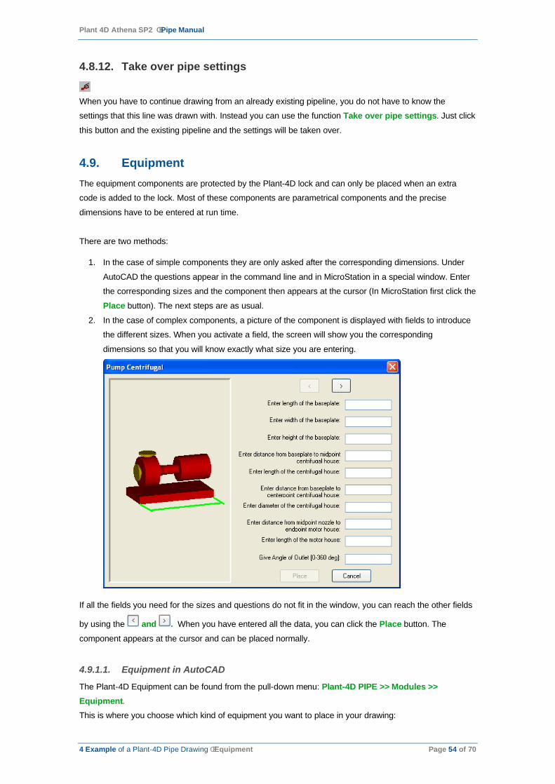
Plant 4D Athena SP2 ê Pipe Manual
4 Example of a Plant-4D Pipe Drawing ê Equipment Page 54 of 70
4.8.12. Take over pipe settings
When you have to continue drawing from an already existing pipeline, you do not have to know the
settings that this line was drawn with. Instead you can use the function Take over pipe settings. Just click
this button and the existing pipeline and the settings will be taken over.
4.9. EquipmentThe equipment components are protected by the Plant-4D lock and can only be placed when an extra
code is added to the lock. Most of these components are parametrical components and the precise
dimensions have to be entered at run time.
There are two methods:
1. In the case of simple components they are only asked after the corresponding dimensions. Under
AutoCAD the questions appear in the command line and in MicroStation in a special window. Enter
the corresponding sizes and the component then appears at the cursor (In MicroStation first click the
Place button). The next steps are as usual.
2. In the case of complex components, a picture of the component is displayed with fields to introduce
the different sizes. When you activate a field, the screen will show you the corresponding
dimensions so that you will know exactly what size you are entering.
If all the fields you need for the sizes and questions do not fit in the window, you can reach the other fields
by using the and . When you have entered all the data, you can click the Place button. The
component appears at the cursor and can be placed normally.
4.9.1.1. Equipment in AutoCAD
The Plant-4D Equipment can be found from the pull-down menu: Plant-4D PIPE >> Modules >>Equipment.This is where you choose which kind of equipment you want to place in your drawing:
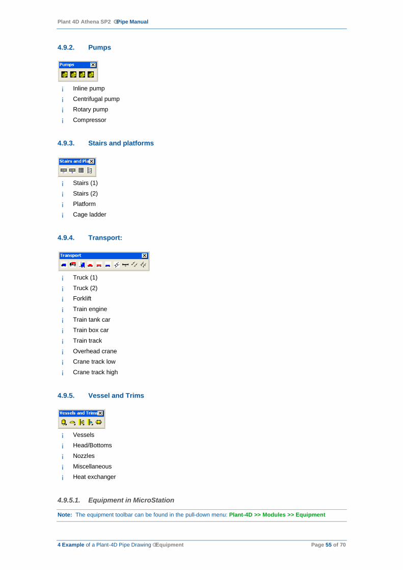
Plant 4D Athena SP2 ê Pipe Manual
4 Example of a Plant-4D Pipe Drawing ê Equipment Page 55 of 70
4.9.2. Pumps
¡ Inline pump
¡ Centrifugal pump
¡ Rotary pump
¡ Compressor
4.9.3. Stairs and platforms
¡ Stairs (1)
¡ Stairs (2)
¡ Platform
¡ Cage ladder
4.9.4. Transport:
¡ Truck (1)
¡ Truck (2)
¡ Forklift
¡ Train engine
¡ Train tank car
¡ Train box car
¡ Train track
¡ Overhead crane
¡ Crane track low
¡ Crane track high
4.9.5. Vessel and Trims
¡ Vessels
¡ Head/Bottoms
¡ Nozzles
¡ Miscellaneous
¡ Heat exchanger
4.9.5.1. Equipment in MicroStation
Note: The equipment toolbar can be found in the pull-down menu: Plant-4D >> Modules >> Equipment
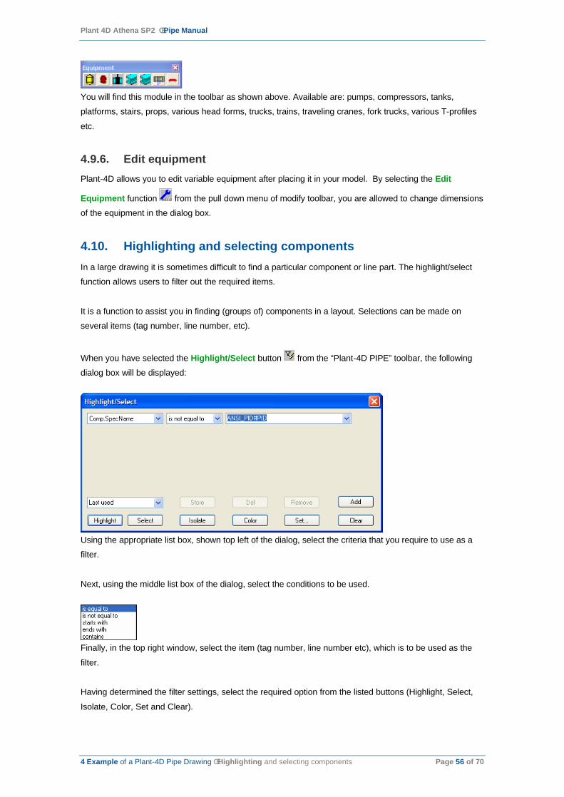
Plant 4D Athena SP2 ê Pipe Manual
4 Example of a Plant-4D Pipe Drawing ê Highlighting and selecting components Page 56 of 70
You will find this module in the toolbar as shown above. Available are: pumps, compressors, tanks,
platforms, stairs, props, various head forms, trucks, trains, traveling cranes, fork trucks, various T-profiles
etc.
4.9.6. Edit equipmentPlant-4D allows you to edit variable equipment after placing it in your model. By selecting the Edit
Equipment function from the pull down menu of modify toolbar, you are allowed to change dimensions
of the equipment in the dialog box.
4.10. Highlighting and selecting componentsIn a large drawing it is sometimes difficult to find a particular component or line part. The highlight/select
function allows users to filter out the required items.
It is a function to assist you in finding (groups of) components in a layout. Selections can be made on
several items (tag number, line number, etc).
When you have selected the Highlight/Select button from the “Plant-4D PIPE” toolbar, the following
dialog box will be displayed:
Using the appropriate list box, shown top left of the dialog, select the criteria that you require to use as a
filter.
Next, using the middle list box of the dialog, select the conditions to be used.
Finally, in the top right window, select the item (tag number, line number etc), which is to be used as the
filter.
Having determined the filter settings, select the required option from the listed buttons (Highlight, Select,
Isolate, Color, Set and Clear).
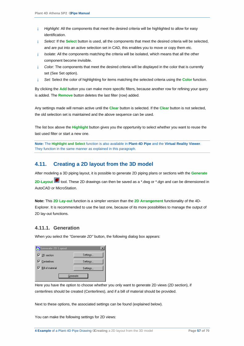
Plant 4D Athena SP2 ê Pipe Manual
4 Example of a Plant-4D Pipe Drawing ê Creating a 2D layout from the 3D model Page 57 of 70
¡ Highlight: All the components that meet the desired criteria will be highlighted to allow for easy
identification.
¡ Select: If the Select button is used, all the components that meet the desired criteria will be selected,
and are put into an active selection set in CAD, this enables you to move or copy them etc.
¡ Isolate: All the components matching the criteria will be isolated, which means that all the other
component become invisible.
¡ Color: The components that meet the desired criteria will be displayed in the color that is currently
set (See Set option).
¡ Set: Select the color of highlighting for items matching the selected criteria using the Color function.
By clicking the Add button you can make more specific filters, because another row for refining your query
is added. The Remove button deletes the last filter (row) added.
Any settings made will remain active until the Clear button is selected. If the Clear button is not selected,
the old selection set is maintained and the above sequence can be used.
The list box above the Highlight button gives you the oppertunity to select whether you want to reuse the
last used filter or start a new one.
Note: The Highlight and Select function is also available in Plant-4D Pipe and the Virtual Reality Viewer. They function in the same manner as explained in this paragraph.
4.11. Creating a 2D layout from the 3D modelAfter modeling a 3D piping layout, it is possible to generate 2D piping plans or sections with the Generate
2D-Layout tool. These 2D drawings can then be saved as a *.dwg or *.dgn and can be dimensioned in
AutoCAD or MicroStation.
Note: This 2D Lay-out function is a simpler version than the 2D Arrangement functionality of the 4D-
Explorer. It is recommended to use the last one, because of its more possibilities to manage the output of
2D lay-out functions.
4.11.1. GenerationWhen you select the "Generate 2D" button, the following dialog box appears:
Here you have the option to choose whether you only want to generate 2D views (2D section), if
centerlines should be created (Centerlines), and if a bill of material should be provided.
Next to these options, the associated settings can be found (explained below).
You can make the following settings for 2D views:
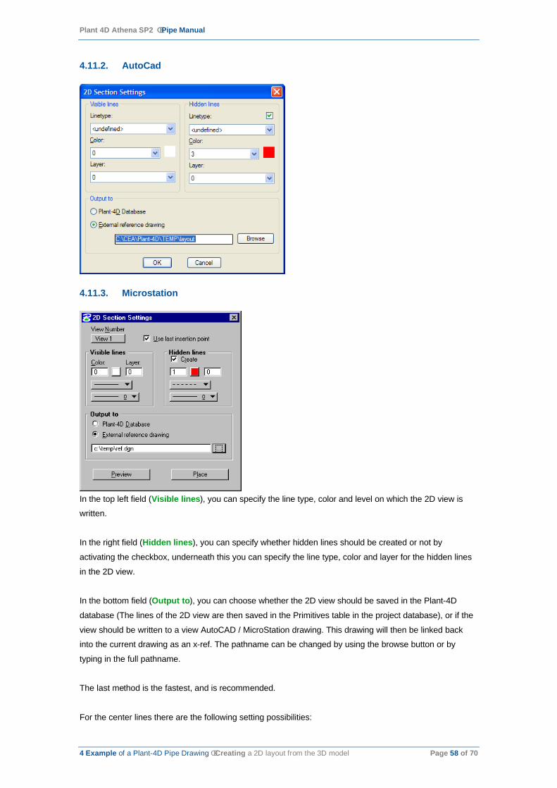
Plant 4D Athena SP2 ê Pipe Manual
4 Example of a Plant-4D Pipe Drawing ê Creating a 2D layout from the 3D model Page 58 of 70
4.11.2. AutoCad
4.11.3. Microstation
In the top left field (Visible lines), you can specify the line type, color and level on which the 2D view is
written.
In the right field (Hidden lines), you can specify whether hidden lines should be created or not by
activating the checkbox, underneath this you can specify the line type, color and layer for the hidden lines
in the 2D view.
In the bottom field (Output to), you can choose whether the 2D view should be saved in the Plant-4D
database (The lines of the 2D view are then saved in the Primitives table in the project database), or if the
view should be written to a view AutoCAD / MicroStation drawing. This drawing will then be linked back
into the current drawing as an x-ref. The pathname can be changed by using the browse button or by
typing in the full pathname.
The last method is the fastest, and is recommended.
For the center lines there are the following setting possibilities:

Plant 4D Athena SP2 ê Pipe Manual
4 Example of a Plant-4D Pipe Drawing ê Creating a 2D layout from the 3D model Page 59 of 70
4.11.4. AutoCAD
4.11.5. MicroStation
In the left field (Line properties) the line type, color and level on which the centerline is to be written are
specified.
In the right field you can set whether the centerline should be created rounded or square for elbows. Below
this option, you can also determine how far the centerline should be extended outside a component at the
end of a line.
For the Bill of Material the following settings can be made:

Plant 4D Athena SP2 ê Pipe Manual
4 Example of a Plant-4D Pipe Drawing ê Creating a 2D layout from the 3D model Page 60 of 70
4.11.6. AutoCAD
4.11.7. MicroStation

Plant 4D Athena SP2 ê Pipe Manual
4 Example of a Plant-4D Pipe Drawing ê Creating a 2D layout from the 3D model Page 61 of 70
In the upper section (Summarize), you can choose if you want to list every pipe part and/or every
component separately.
In the middle section (Piecemarks), you can choose if you want to attribute piecemarks and which
piecemark will be started with.
In the bottom section (Scale) you can also determine on which scale the bill of material will be written.
When all the necessary settings have been made, select the Generate button.
You will then be asked for a view and an origin point from where you want to generate the view. Click on
the corresponding position in the drawing.
The generation starts.
When completed you will be asked for the starting point and the direction for placing the view in the active
drawing. Provide these by using the cross-hairs or co-ordinates.
If a BOM (Bill of Material) was requested, this will now be displayed at the cross hairs and can be
positioned in the same manner. If piecemarks were also requested these are positioned one at a time and
will be automatically connected appropriately.

Plant 4D Athena SP2 ê Pipe Manual
5 Isometrics ê Creating isometrics Page 62 of 70
5. Isometrics
Personal Isogen is used for the creation of isometrics from a 3D Plant-4D Piping model.
This full version of Isogen in fully integrated in the Plant-4D software.
The Isometric generation is done by converting a 3D piping model by line number into an external *.DXF
file. Several option switches can define the layout and appearance of the isometric like:
¡ Border sheet
¡ Material list
¡ Process Data
¡ Component Data
¡ Component representation
¡ Dimensioning
¡ Welding information
5.1. Creating isometricsAs mentioned before, the isometric is generated from the 3D piping model. The generation is started from
the 4D-Explorer. From there you can start the isometrics tool (Isogen) on several ways:
1. You can select Generate Iso’s… from the popup menu appearing after a click with the right mouse
button on a PIPE-model. From here you can generate an isometric for every process line in the
project
2. When you select Start from the popup menu appearing after a click with the right mouse button on a
PIPE-model, the following dialog will be shown:
By selecting Isometric generation, you can generate an isometric for every process line in the project.
3. Browse to the appropriate process line beneath the PIPE-model this line is (partially) drawn in.
.

Plant 4D Athena SP2 ê Pipe Manual
5 Isometrics ê Plant-4D to Iso Page 63 of 70
By clicking the right mouse button, you can select Iso per Linenumber from the appearing popup menu.
From here an isometric will be directly generated for this particular process line, without needing to select a
line.
5.2. Plant-4D to IsoWhen the Plant-4D to Iso module is started the application initializes the Plant-4D model and the following
dialog appears:
When clicking the Select button, the following dialog appears:
On the left-hand side of the dialog, a window with the available line numbers from the selected drawing are
displayed in alphabetical order.
Selections can be made in the window to the right.
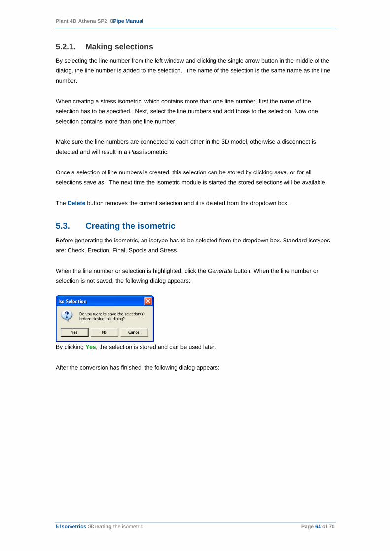
Plant 4D Athena SP2 ê Pipe Manual
5 Isometrics ê Creating the isometric Page 64 of 70
5.2.1. Making selectionsBy selecting the line number from the left window and clicking the single arrow button in the middle of the
dialog, the line number is added to the selection. The name of the selection is the same name as the line
number.
When creating a stress isometric, which contains more than one line number, first the name of the
selection has to be specified. Next, select the line numbers and add those to the selection. Now one
selection contains more than one line number.
Make sure the line numbers are connected to each other in the 3D model, otherwise a disconnect is
detected and will result in a Pass isometric.
Once a selection of line numbers is created, this selection can be stored by clicking save, or for all
selections save as. The next time the isometric module is started the stored selections will be available.
The Delete button removes the current selection and it is deleted from the dropdown box.
5.3. Creating the isometricBefore generating the isometric, an isotype has to be selected from the dropdown box. Standard isotypes
are: Check, Erection, Final, Spools and Stress.
When the line number or selection is highlighted, click the Generate button. When the line number or
selection is not saved, the following dialog appears:
By clicking Yes, the selection is stored and can be used later.
After the conversion has finished, the following dialog appears:

Plant 4D Athena SP2 ê Pipe Manual
5 Isometrics ê Creating the isometric Page 65 of 70
The isometric module has generated an isometric.dxf and is displayed when the OK button is clicked in a
Plant-4D dxf-viewer.

Plant 4D Athena SP2 ê Pipe Manual
5 Isometrics ê Options Page 66 of 70
5.3.1. Viewing the Isometric(s)
5.3.1.1. DXF-Viewer
The Plant-4D dxf-viewer is for viewing only. Making modifications or printing of the isometric is not possible
in this application. The modifications and printing has to be done in AutoCAD or Microstation.
By clicking the right mouse button in the Plant-4D dxf-viewer, the zoom functions become available:
Other Zoom Functions are:
CTRL-Left mouse button
Zoom Window
ALT-Left mouse button Pan
When the linenumber is split into two or more drawings, these drawings can be selected from the
dropdown box in the top of the dxf-viewer.
5.3.1.2. Opening the Isometric in CAD
The isometic.dxf file is located in the following folder:
<drive>:\CEA\Plant-4d\Pisogen\Projects\Prj_n\<Isotype>\Output\
The isometric can be opened and printed or modified in AutoCAD or Microstation. Changing this isometric
will not update the 3D model.
5.4. OptionsBefore the Isometric is generated, several option settings in Plant-4D to Iso can be made. The options
dialog is displayed after clicking on the options button from the Plant-4D to Iso initialize window.
5.4.1. TransformationBy checking the Rotate North switch the plant-north can be rotated to the required plant-rotation. The
default plant-rotation is set to zero.
Plant 4D Athena SP2 ê Pipe Manual
5 Isometrics ê Options Page 67 of 70
5.4.2. DisplacementOn the isometric the coordinates of the piping system are related to the CAD orgin 0,0,0. To redefine the
coordinates on the isometric to a new origin, set the displacement values in the XYZ edit boxes.
5.4.3. Node CheckingThe Plant-4D to Iso generation can only produce a valid Isometric when all nodes of the same linenumber
are connected to each other. When the nodes are not connected to each other a Pass isometric is
generated.
To locate the disconnections, switch the Place primitives at free nodes option. This option places cones at
disconnects in the 3D model, so the error can easily be found.
5.4.4. ErrorsCheck the option “Place primitives at free nodes” to generate 3D cones into the piping model on each free
node. This will simplify finding disconnections in the model. By opening or refreshing the piping model, the
3D cones will be visible. The size, layer and color can be defined using the other fields of the dialog box.
The cones have to be deleted manually from the model or primitives table.


![Athena Optics.ppt [Kompatibilitätsmodus] · ATHENA Optics First German ATHENA Science Workshop, January 13, 2012, Garching, Germany 1 ... (ESA led studies for XEUS/IXO/Athena) •](https://static.fdocuments.in/doc/165x107/5e7c8b679ccbb82b722f38d8/athena-kompatibilittsmodus-athena-optics-first-german-athena-science-workshop.jpg)