Manual, GB - DIYTrade.comdoc.diytrade.com/docdvr/165826/3963067/1184456377.doc · Web viewChange...
13
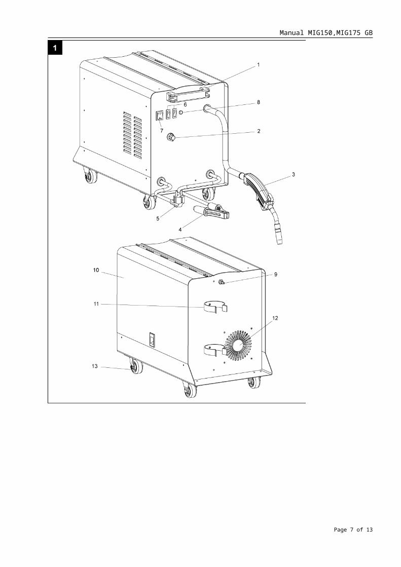
Manual MIG150,MIG175 GB Description 1. Carrying handling 2. Wire feed rate regulator 3. Torch 4. Earth clamp 5. Power cable 6. Welding current step selector switch 7. On/Off switch 8. Overheat indicator 9. Gas inlet 10. Wire feed unit door 11. Gas cylinder holder 12. Ventilator Safety instructions The safety instructions must be observed when using arc welding machine. For your own safety and the safety of others, please read this information carefully before using the machine and keep it in a safe place for reference. Use the machine only for its designed purpose. Any other types of use are at your own risk and could be dangerous. The manufacturer cannot be held liable for damage caused by improper or incorrect usage. To prevent the incorrect handling of the machine, please read the operating instructions in their entirety before starting for the first time. All the information on the handling of the machine is relevant to your personal safety. Ask a professional to show you how to use this machine! ● Before plugging in, check the plug and cable for damage. If damage is discovered, have it repaired by a specialist immediately. Do not undertake any permanent or temporary repairs. ● Never use a damaged cable, connection or plug or a power cable which does not comply with the requirements. If the cable is damaged or severed, unplug immediately. ● Protect the cables from damage by heavy mechanical use, sharp edges, contact with moving parts and corrosive liquids, etc. ● Never move the machine by pulling at the cables. ● Always wear protective gloves made of insulating material. ● Wear suitable insulating shoes. ● Do not look into the arc with the naked eye. Use only face shields with filters complying with DIN standards. The arc produces not only light, which could cause dazzling or permanent eye injury, and infrared (heat) rays which can cause burns; it also generates UV. If eye protection is not sufficient these ultraviolet rays, invisible to the eye, can cause extremely painful inflammation of the eyeball which will usually be first noticed only several hours after exposure. Furthermore, ultraviolet rays will have an effect similar to sunburn on unprotected skin areas. ● Avoid exposure of skin to hazards such as electric shock, ultraviolet rays given off by electric fumes. ● Make sure you have a firm footing when working with the machine. ● Keep your place of work tidy. Ensure the area has adequate ventilation to prevent the formation of harmful fumes and toxic gases. ● Do not use the machine in the areas of combustible liquids or gases. Do not weld in areas where Page 1 of 13
Transcript of Manual, GB - DIYTrade.comdoc.diytrade.com/docdvr/165826/3963067/1184456377.doc · Web viewChange...

Manual MIG150,MIG175 GB
Description
1. Carrying handling 2. Wire feed rate regulator3. Torch4. Earth clamp5. Power cable6. Welding current step selector switch7. On/Off switch8. Overheat indicator9. Gas inlet10. Wire feed unit door11. Gas cylinder holder12. Ventilator
Safety instructions
The safety instructions must be observed when using arc welding machine. For your own safety and the safety of others,
please read this information carefully before using the machine and keep it in a safe place for reference. Use the machine only
for its designed purpose. Any other types of use are at your own risk and could be dangerous. The manufacturer cannot be
held liable for damage caused by improper or incorrect usage.
To prevent the incorrect handling of the machine, please read the operating instructions in their entirety before starting for the
first time. All the information on the handling of the machine is relevant to your personal safety. Ask a professional to show
you how to use this machine!
● Before plugging in, check the plug and cable for damage. If damage is discovered, have it repaired by a specialist immediately . Do
not undertake any permanent or temporary repairs.
● Never use a damaged cable, connection or plug or a power cable which does not comply with the requirements. If the cable is
damaged or severed, unplug immediately.
● Protect the cables from damage by heavy mechanical use, sharp edges, contact with moving parts and corrosive liquids, etc.
● Never move the machine by pulling at the cables.
● Always wear protective gloves made of insulating material.
● Wear suitable insulating shoes.
● Do not look into the arc with the naked eye. Use only face shields with filters complying with DIN standards. The arc produces not
only light, which could cause dazzling or permanent eye injury, and infrared (heat) rays which can cause burns; it also generates
UV. If eye protection is not sufficient these ultraviolet rays, invisible to the eye, can cause extremely painful inflammation of the
eyeball which will usually be first noticed only several hours after exposure. Furthermore, ultraviolet rays will have an effect similar
to sunburn on unprotected skin areas.
● Avoid exposure of skin to hazards such as electric shock, ultraviolet rays given off by electric fumes.
● Make sure you have a firm footing when working with the machine.
● Keep your place of work tidy. Ensure the area has adequate ventilation to prevent the formation of harmful fumes and toxic gases.
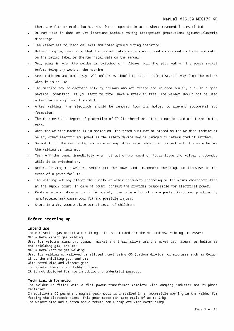
● Do not use the machine in the areas of combustible liquids or gases. Do not weld in areas where there are fire or explosion
hazards. Do not operate in areas where movement is restricted.
● Do not weld in damp or wet locations without taking appropriate precautions against electric discharge.
● The welder has to stand on level and solid ground during operation.
● Before plug in, make sure that the socket ratings are correct and correspond to those indicated on the rating label or the technical
date on the manual.
● Only plug in when the welder is switched off. Always pull the plug out of the power socket before doing any work on the machine.
● Keep children and pets away. All onlookers should be kept a safe distance away from the welder when it is in use.
● The machine may be operated only by persons who are rested and in good health, i.e. in a good physical condition. If you start to
tire, have a break in time. The welder should not be used after the consumption of alcohol.
Page 1 of 12
Manual MIG150,MIG175 GB
● After welding, the electrode should be removed from its holder to prevent accidental arc formation.
● The machine has a degree of protection of IP 21; therefore, it must not be used or stored in the rain.
● When the welding machine is in operation, the torch must not be placed on the welding machine or on any other electric equipment
as the safety device may be damaged or interrupted if earthed.
● Do not touch the nozzle tip and wire or any other metal object in contact with the wire before the welding is finished.
● Turn off the power immediately when not using the machine. Never leave the welder unattended while it is switched on.
● Before leaving the welder, switch off the power and disconnect the plug. Do likewise in the event of a power failure.
● The welding set may affect the supply of other consumers depending on the mains characteristics at the supply point. In case of
doubt, consult the provider responsible for electrical power.
● Replace worn or damaged parts for safety. Use only original spare parts. Parts not produced by manufacturer may cause poor fit
and possible injury.
● Store in a dry secure place out of reach of children.
Before starting up
Intend useThe MIG series gas mental-arc welding unit is intended for the MIG and MAG welding processes:MIG = Metal-inert gas weldingUsed for welding aluminum, copper, nickel and their alloys using a mixed gas, argon, or helium as the shielding gas, and or;MAG = Metal-active gas weldingUsed for welding non-alloyed or alloyed steel using CO2 (carbon dioxide) or mixtures such as Corgon 18 as the shielding gas, and or;with cored wire and without gas;in private domestic and hobby purpose.It is not designed for use in public and industrial purpose.
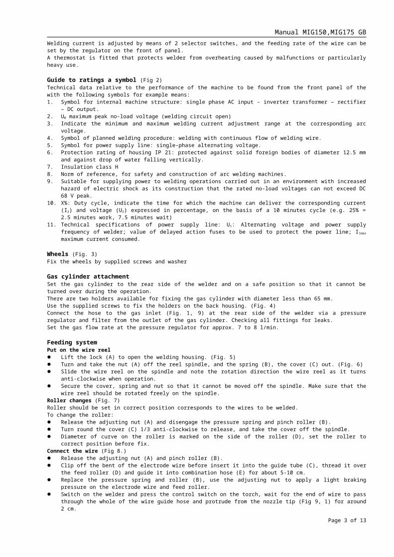
Technical informationThe welder is fitted with a flat power transformer complete with damping inductor and bi-phase rectifier.In addition a DC permanent magnet gear-motor is installed in an accessible opening in the welder for feeding the electrode wires. This gear-motor can take reels of up to 5 kg.The welder also has a torch and a return cable complete with earth clamp.Welding current is adjusted by means of 2 selector switches, and the feeding rate of the wire can be set by the regulator on the front of panel.A thermostat is fitted that protects welder from overheating caused by malfunctions or particularly heavy use.
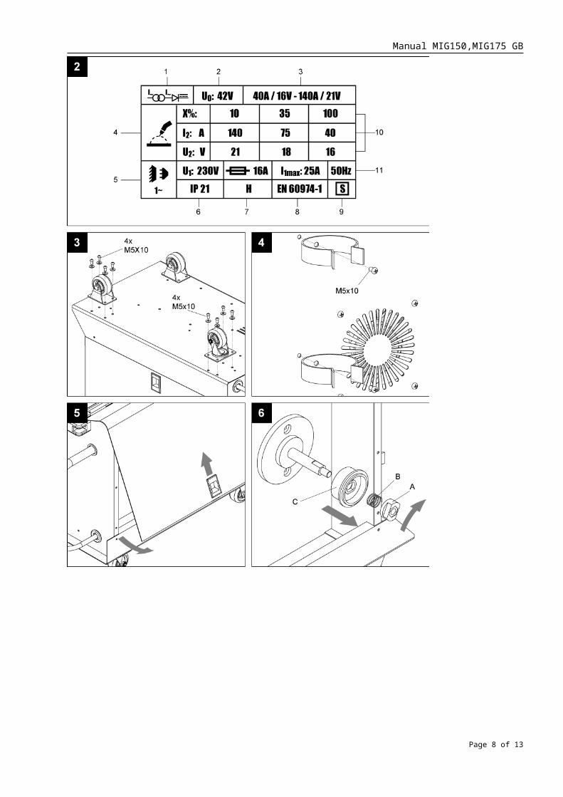
Guide to ratings a symbol (Fig 2)Technical data relative to the performance of the machine to be found from the front panel of the with the following symbols for example means:1. Symbol for internal machine structure: single phase AC input - inverter transformer – rectifier – DC output.2. U0 maximum peak no-load voltage (welding circuit open)3. Indicate the minimum and maximum welding current adjustment range at the corresponding arc voltage.4. Symbol of planned welding procedure: welding with continuous flow of welding wire.5. Symbol for power supply line: single-phase alternating voltage.6. Protection rating of housing IP 21: protected against solid foreign bodies of diameter 12.5 mm and against drop of water falling
vertically.7. Insulation class H8. Norm of reference, for safety and construction of arc welding machines.9. Suitable for supplying power to welding operations carried out in an environment with increased hazard of electric shock as its
construction that the rated no-load voltages can not exceed DC 68 V peak.10. X%: Duty cycle, indicate the time for which the machine can deliver the corresponding current (I 2) and voltage (U2) expressed in
percentage, on the basis of a 10 minutes cycle (e.g. 25% = 2.5 minutes work, 7.5 minutes wait)11. Technical specifications of power supply line: U1: Alternating voltage and power supply frequency of welder; value of delayed
action fuses to be used to protect the power line; I1max maximum current consumed.
Wheels (Fig. 3)Fix the wheels by supplied screws and washer
Gas cylinder attachmentSet the gas cylinder to the rear side of the welder and on a safe position so that it cannot be turned over during the operation. There are two holders available for fixing the gas cylinder with diameter less than 65 mm.Use the supplied screws to fix the holders on the back housing. (Fig. 4)Connect the hose to the gas inlet (Fig. 1, 9) at the rear side of the welder via a pressure regulator and filter from the outlet of the gas cylinder. Checking all fittings for leaks.Set the gas flow rate at the pressure regulator for approx. 7 to 8 l/min.
Feeding systemPut on the wire reel Lift the lock (A) to open the welding housing. (Fig. 5) Turn and take the nut (A) off the reel spindle, and the spring (B), the cover (C) out. (Fig. 6) Slide the wire reel on the spindle and note the rotation direction the wire reel as it turns anti-clockwise when operation.
Page 2 of 12
Manual MIG150,MIG175 GB
Secure the cover, spring and nut so that it cannot be moved off the spindle. Make sure that the wire reel should be rotated freely on the spindle.
Roller changes (Fig. 7)Roller should be set in correct position corresponds to the wires to be welded.To change the roller: Release the adjusting nut (A) and disengage the pressure spring and pinch roller (B). Turn round the cover (C) 1/3 anti-clockwise to release, and take the cover off the spindle. Diameter of curve on the roller is marked on the side of the roller (D), set the roller to correct position before fix.Connect the wire (Fig 8.) Release the adjusting nut (A) and pinch roller (B). Clip off the bent of the electrode wire before insert it into the guide tube (C), thread it over the feed roller (D) and guide it into
combination hose (E) for about 5-10 cm. Replace the pressure spring and roller (B), use the adjusting nut to apply a light braking pressure on the electrode wire and feed
roller. Switch on the welder and press the control switch on the torch, wait for the end of wire to pass through the whole of the wire guide
hose and protrude from the nozzle tip (Fig 9, 1) for around 2 cm.NoteDuring this operation the wire is live and subject to mechanical stress, therefore if adequate precautions are not taken the wire could cause electric shock, injury and inadvertent striking of electric arc.Check the diameter of the collet (Fig 9, 2), it must be corresponded the diameter of the wire. Replace the collet if necessary.To replace the collet: Pull the nozzle tip (1) out of the torch Unscrew and replace the collect with the correct one.
Connection to mainsBefore making any electrical connection check that the mains supply correspond with the voltage ratings on the data table and welders. The welder is to be fed with two conductors (phase-neutral) plus a third separate one designed for protective earth connection.
Starting up
Preparations for weldingAttach the grounding clamp to the workpiece.Open the valve on the gas cylinder and set the flow rate at the pressure reducer.The welder is now ready for operation. Controls are to be set in accordance with the job at hand:Welding current step selector switch:Set the welding current depends on demands as printed on the control panel of the welder.
Position MIG 150 MIG-175
MIN + 1 40 A 45AMIN + 2 75 A 80AMAX + 1 105 A 120AMAX + 2 shown in Fig. 10 140 A 160A
Wire feed control: The wire feed rate can be adjusted infinitely.
Operation
Insure that there is full contact at the grounding clamp (remove any rust or paint before attaching).The distance between the torch and the weldment during welding must be chosen to correspond to the welding current selected: High welding current = larger distance - Low welding current = shorter distance.Holding the tip too close to the work at high current levels will place excessive loads on the gas nozzle and the collet.If the tip is held too far from the work the shielding effect of the gas supplied will no longer be sufficient; the weld will be porous.If the electrode wire fluxes drop by drop and the arc is irregular, the welding current will have to be reduced, or the feed rate increased.If, on the other hand, the wire “pushes” against the workpiece, then increase the welding current or reduce the feed rate.Varying wire qualities will require different adjustments of the current steps and the feed speed. It is therefore advisable to check these settings by making test welds on scrap pieces.
Overheat protectionThere is a thermal protector inside the transformer to protect the machine overheat on heavy duty condition.The yellow indicator on the front panel will light up while the thermal protector act in to cut the mains automatically. Wait the machine cool down before resume work after the yellow indicator turn off for around 15 minutes depends on the weather temperature.
Troubleshooting
Wire is not fed cause.1) Pinch roller not applying pressure.
Adjust the screw to tight down the pressure spring.2) Control line to the torch control switch interrupted.
Check the control line for continuity.3) Control electronics defective.
Change out the control electronics.
Irregular wire feed.1) Pinch roller pressure insufficient.
Increase pinch roller pressure.
Page 3 of 12

Manual MIG150,MIG175 GB
2) Wire reel brake too tight.Loosen wire reel brake.
3) Feed roller dirty or wrong size.Clean or replace the feed roller.
4) Wire guide core clogged.Remove the wire guide from the combination hose and clean the core and the hose with compressed air.
5) Electrode wire poorly wound on the reel or rusted.Change out wire reel.
Welding seam porous.1) Workpiece surface not clean (paint, rust, grease).
Clean the surface of the workpiece.2) Too much or too little gas supplied.
Set the gas supply at the pressure regulator.3) Gas leakage and loss.
Check the connections and threaded fittings for leaks.4) Draft in the welding area.
Either screen off the workplace or increase gas flow rate.5) Gas nozzle or combination hose clogged.
Clean the gas nozzle and the combination hose.6) Incorrect selection of shielding gas.
Use gas mixture.
Arc is struck when gas nozzle touches the workpiece.Short circuit between the collet and the gas nozzle.Clean the gas nozzle and the torch tube and spray with welding gun spray.
Torch gets too hot.Collet loose or too large.Screw down the collet tight or change out against one of the correct size.
Care and maintenance
Always disconnect the unit from the power supply before commencing work on the welder!Compressed air is to be used to blow out the core of the hose combination and the wire feed unit at every change of the wire reel. Depending on the amount of dust in the atmosphere, the inside of the unit should be cleaned with compressed air every 15 to 20 weeks. Regularly remove welding globules from the gas nozzle and the collet and spray with an abherent agent to prevent seizing (spray the inside surface of the gas nozzle, not the collet direct).Worn components such as the gas nozzle, collet, wire guide tube and feed rollers are to be replaced with new parts.
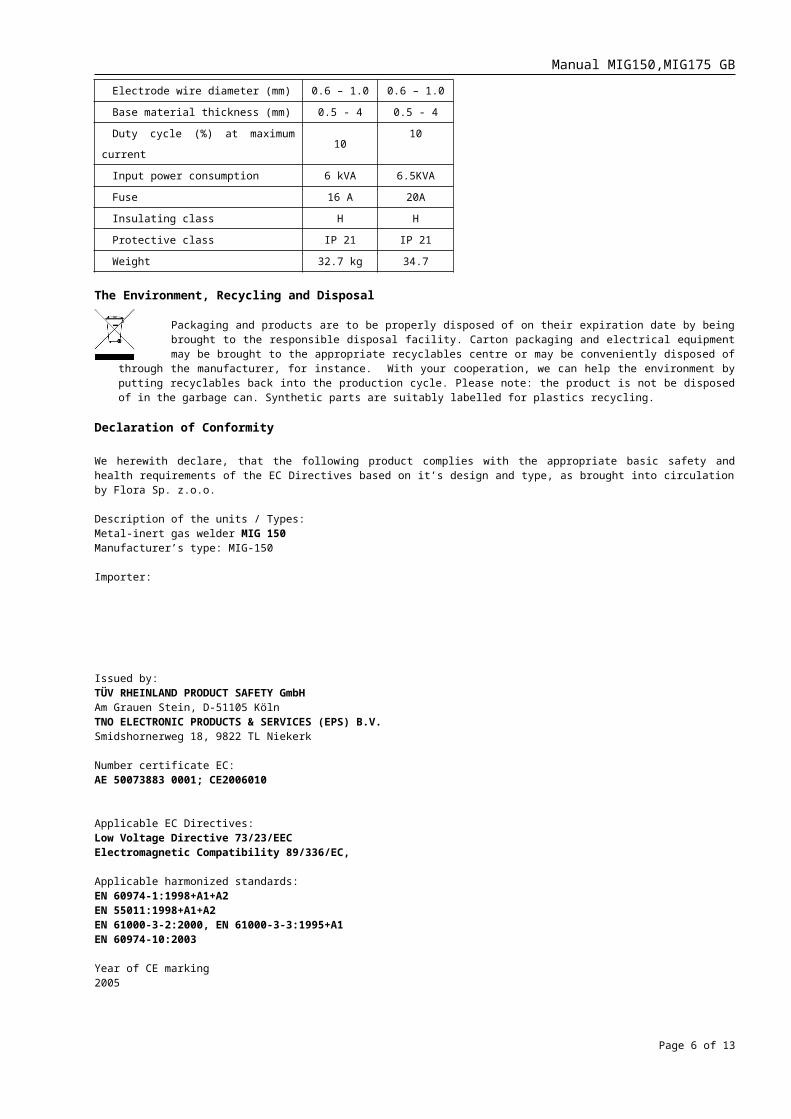
Technical data
MIG-150 MIG-175
Welding current adjustment range 40 - 140 A 45-160A
Operating voltage U2 16 - 21 V 16.2-22A
Iding voltage U0 23 - 42 V 23-42
Switching steps 4 4
Electrode wire diameter (mm) 0.6 – 1.0 0.6 – 1.0
Base material thickness (mm) 0.5 - 4 0.5 - 4
Duty cycle (%) at maximum current 10 10
Input power consumption 6 kVA 6.5KVA
Fuse 16 A 20A
Insulating class H H
Protective class IP 21 IP 21
Weight 32.7 kg 34.7
The Environment, Recycling and Disposal
Packaging and products are to be properly disposed of on their expiration date by being brought to the responsible disposal facility. Carton packaging and electrical equipment may be brought to the appropriate recyclables centre or may be conveniently disposed of through the manufacturer, for instance. With your cooperation, we can help the environment by putting recyclables back into the production cycle. Please note: the product is not be disposed of in the
garbage can. Synthetic parts are suitably labelled for plastics recycling.
Declaration of Conformity
Page 4 of 12

Manual MIG150,MIG175 GB
We herewith declare, that the following product complies with the appropriate basic safety and health requirements of the EC Directives based on it’s design and type, as brought into circulation by Flora Sp. z.o.o.
Description of the units / Types:Metal-inert gas welder MIG 150Manufacturer’s type: MIG-150
Importer:
Issued by: TÜV RHEINLAND PRODUCT SAFETY GmbH Am Grauen Stein, D-51105 KölnTNO ELECTRONIC PRODUCTS & SERVICES (EPS) B.V.Smidshornerweg 18, 9822 TL Niekerk
Number certificate EC: AE 50073883 0001; CE2006010
Applicable EC Directives:Low Voltage Directive 73/23/EECElectromagnetic Compatibility 89/336/EC,
Applicable harmonized standards:EN 60974-1:1998+A1+A2EN 55011:1998+A1+A2EN 61000-3-2:2000, EN 61000-3-3:1995+A1EN 60974-10:2003
Year of CE marking2005
Page 5 of 12
Manual MIG150,MIG175 GB
Page 6 of 12
Manual MIG150,MIG175 GB
Page 7 of 12
Manual MIG150,MIG175 GB
Page 8 of 12

Manual MIG150,MIG175 GB
Page 9 of 12

Manual MIG150,MIG175 GB
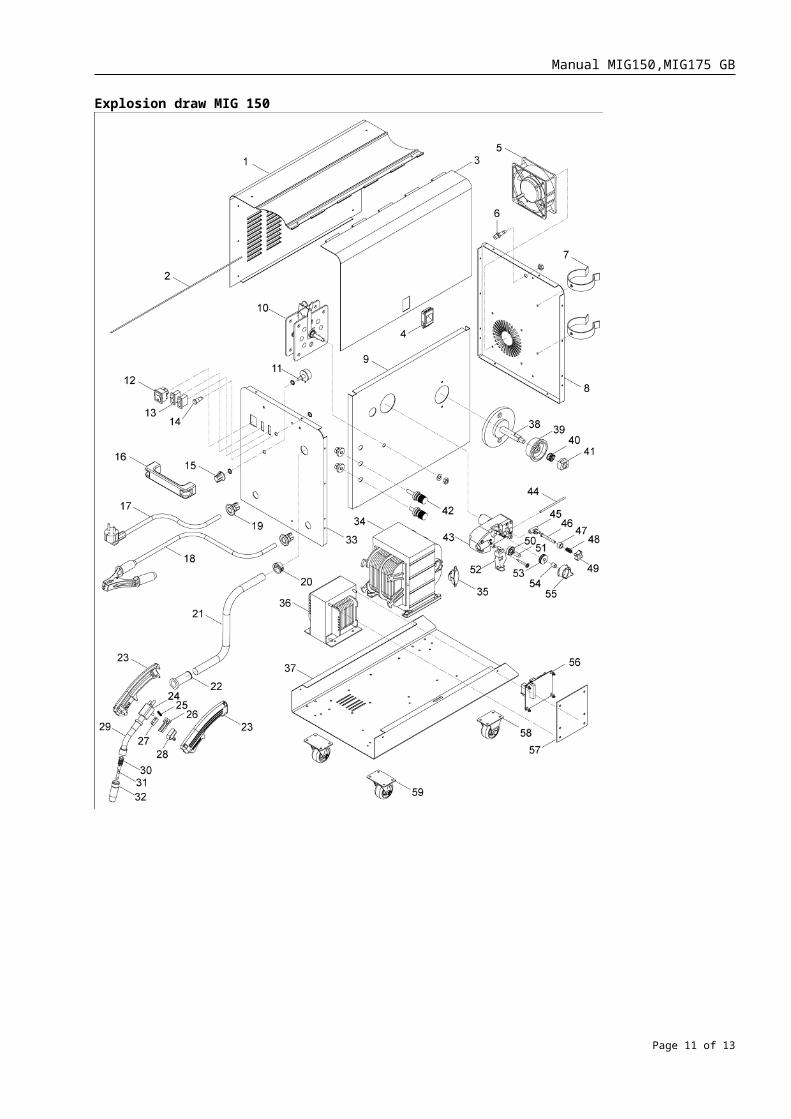
Explosion draw MIG 150
Page 10 of 12
Manual MIG150,MIG175 GB
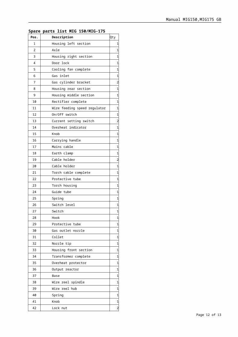
Spare parts list MIG 150/MIG-175Pos. Description Qty
1 Housing left section 1
2 Axle 1
3 Housing right section 1
4 Door lock 1
5 Cooling fan complete 1
6 Gas inlet 1
7 Gas cylinder bracket 2
8 Housing rear section 1
9 Housing middle section 1
10 Rectifier complete 1
11 Wire feeding speed regulator 1
12 On/Off switch 1
13 Current setting switch 2
14 Overheat indicator 1
15 Knob 1
16 Carrying handle 1
17 Mains cable 1
18 Earth clamp 1
19 Cable holder 2
20 Cable holder 1
21 Torch cable complete 1
22 Protective tube 1
23 Torch housing 1
24 Guide tube 1
25 Spring 1
26 Switch level 1
27 Switch 1
28 Hook 1
29 Protective tube 1
30 Gas outlet nozzle 1
31 Collet 1
32 Nozzle tip 1
33 Housing front section 1
34 Transformer complete 1
35 Overheat protector 1
36 Output reactor 1
37 Base 1
38 Wire reel spindle 1
39 Wire reel hub 1
40 Spring 1
41 Knob 1
42 Lock nut 2
Page 11 of 12
Manual MIG150,MIG175 GB
43 Wire feeding motor complete 1
44 Guide tube 1
45 Pressure adjusting device holder 1
46 Hex bolt M6x45 1
47 Spring seat 1
48 Friction spring 1
49 Knob 1
50 Bearing 609Z 1
51 Bearing axle 1
52 Pinch roller holder 1
53 Feed roller 1
54 Bearing 1
55 Feed roller cover 1
56 Wire feeding speed regulating board 1
57 Support 1
58 Wheel 2
59 Wheel 2
Page 12 of 12