Manual Bematech mp 4000 th fi
34
-
Upload
vacosteles -
Category
Documents
-
view
239 -
download
8
description
Impresora
Transcript of Manual Bematech mp 4000 th fi

MP-4000 TH User’s Manual P/N: 501.1101.00 - Rev.1.3 March 2008 (First edition: December 2006) Copyright© by Bematech S.A, Curitiba-PR, Brazil. All rights reserved. No part of this publication may be copied, reproduced, adapted or translated without the prior written permission of Bematech S.A., except when allowed by patent rights. Information in this publication is purely informative, subject to change without notice and no liability is assumed with respect to its use. However, as product improvements become available, Bematech S.A. will make every effort to provide updated information for the products described in this publication. The latest version of this manual can be obtained through Bematech website:
www.bematech.com Notwithstanding the other exceptions contained in this Manual, the consequences and responsibility are assumed by the Purchaser of this product or third parties as a result of: (a) intentional use for any improper, unintended or unauthorized applications of this product, including any particular purpose; (b) unauthorized modifications, repairs, or alterations to this product; (c) use of the product without complying with Bematech S.A. operating and maintenance instructions; (d) use of the product as a component in systems or other applications in which its failure could create a situation where personal injury or material damages may occur. In the events described above, Bematech S.A. and its officers, administrators, employees, subsidiaries, affiliates and dealers shall not be held responsible for or respond by any claim, costs, damages, losses, expenses and any other direct or indirect injury, as well as claims alleging that Bematech S.A. has been negligent regarding the design or manufacture of the product. Bematech S.A. shall not be liable against any damages or problems arising from the use of any options or any consumable products other than those designated as original Bematech products or approved products by Bematech S.A. Any product names or its logotypes mentioned in this publication may be trademarks of its respective owners and shall be here recognized. Product warranties are only the ones expressly mentioned in the Quick Start. Bematech S.A. disclaims any and all implied warranties for the product, including but not limited to implied warranties of merchantability or fitness for a particular purpose. In addition, Bematech S.A. shall not be responsible or liable for any special, incidental or consequential damages or lost profits or savings arising from the use of the product by the Purchaser, the User or third parties.
MP-4000 TH . Revision 1.3
3
Contents
Preface .................................................................................................................... 6 1. Who should read this manual?..........................................................................6 2. How this manual is organized? .........................................................................6 3. Related publications and software .....................................................................6 4. Where to find more information ........................................................................6
EMC, Safety and Other Applicable Standards ........................................................... 7 5. FCC Compliance Statement..............................................................................7 6. RoHS............................................................................................................7 7. UL................................................................................................................8 8. NOM-019-SCFI-1998 ......................................................................................8 9. WEEE ...........................................................................................................8
9.1. Disposal and Recycling Information (End of Life Disposal) ...............................8
Safety Information .................................................................................................. 9 10. Safety Labels .................................................................................................9 11. Protection Features.........................................................................................9
End of Life Disposal ................................................................................................. 9
Chapter 1 ........................................................................................... 10
Getting Started......................................................................................................... 10
Product Overview .................................................................................................. 10 12. Introduction................................................................................................. 10 13. Product Characteristics.................................................................................. 11 14. Software and Drivers .................................................................................... 11 15. Typical Applications ...................................................................................... 11 16. Description of Models .................................................................................... 11 17. Optional Items and Accessories ...................................................................... 12
Chapter 2 ........................................................................................... 13
Setting Up Your Product ........................................................................................... 13
Installing ............................................................................................................... 13 18. Plugging in the Power Adapter........................................................................ 14 19. Turn on Your Product .................................................................................... 15 20. Inserting or Changing the Paper Roll ............................................................... 15 21. Connecting the Communication Cables ............................................................ 16
21.1. Cash Drawer Connection .......................................................................... 16 21.2. Connection of the communication Interface boards ...................................... 16
Configuring............................................................................................................ 17 22. Language Configuration................................................................................. 17 23. Print Density Configuration ............................................................................ 18

User’s Manual
4
24. Near End Paper Sensor Configuration .............................................................. 18 24.1. Adjusting the Paper Length in the Near-End-Paper Sensor Indicator ............... 18
25. Paper Width / Print Width Configuration........................................................... 18 25.1. Adjusting the Paper Width ........................................................................ 19
26. Command Set Configuration .......................................................................... 19 27. Print Mode Configuration ............................................................................... 19
Communication Interface Configuration ................................................................ 20 28. Inserting or Changing the Communication Interface .......................................... 20 29. RS-232 Serial Interface (DB-9 /DB-25 connector) ............................................. 20
29.1. Specifications ......................................................................................... 20 29.2. Dip Switches .......................................................................................... 20
30. Cable Connection ......................................................................................... 22 30.1. Parallel Interface..................................................................................... 23 30.2. Specification........................................................................................... 23 30.3. Cable connection .................................................................................... 23
31. USB Interface .............................................................................................. 24 31.1. Specification........................................................................................... 24 31.2. Cable connection .................................................................................... 24
32. Ethernet Interface ........................................................................................ 24 32.1. Specification........................................................................................... 24 32.2. Cable connection .................................................................................... 25 32.3. Cash Drawer Interface ............................................................................. 26
Chapter 3 ........................................................................................... 27
How to Use Your Product.......................................................................................... 27
User Interface ....................................................................................................... 27 33. Keyboard .................................................................................................... 27 34. LEDs........................................................................................................... 28
Operation Modes.................................................................................................... 28 35. Normal Mode ............................................................................................... 28 36. Other optional modes.................................................................................... 28
36.1. Self Test Mode........................................................................................ 28 36.2. Configuration Mode ................................................................................. 28 36.3. Dump Mode ........................................................................................... 29
Software................................................................................................................ 29 37. Drivers........................................................................................................ 29
37.1. API Drivers ............................................................................................ 29 37.2. Spooler Drivers....................................................................................... 29
38. User Utility Software ..................................................................................... 29 38.1. Firmware Upgrading ................................................................................ 29
Preventive Maintenance ........................................................................................ 29 39. Print Head ................................................................................................... 29 40. Sensors ...................................................................................................... 30

MP-4000 TH . Revision 1.3
5
41. Cutter......................................................................................................... 30 42. External Cleaning ......................................................................................... 30
Chapter 4 ........................................................................................... 31
Troubleshooting ....................................................................................................... 31
Chapter 5 ........................................................................................... 33
Technical Specifications ........................................................................................... 33
User’s Manual
6
Preface This manual assists you with the installation, configuration and usage of this Bematech product.
1. Who should read this manual? This manual is intended for use by persons who are installing, using or testing the product. The manual should also be used for product troubleshooting.
2. How this manual is organized? Chapter 1 - "Getting Started" provides an overview about the product. Chapter 2 - "Setting Up Your Product" provides information on installing and configuring the product. Chapter 3 - "How To Use Your Product" provides information on using the product effectively. Chapter 4 - "Troubleshooting" provides information on testing and identifying simple solutions to the most common problems. Chapter 5 - "Technical Specifications" provides technical information about the product.
3. Related publications and software - Quick Start Guide - Programmer's Manual - Drivers and APIs These contents are available at our website.
4. Where to find more information English contents in http://www.bematech.com Spanish contents in http://www.bematech.com/es Portuguese contents in http://www.bematech.com.br

MP-4000 TH . Revision 1.3
7
EMC, Safety and Other Applicable Standards Product Name: MP-4000 TH The following standards apply only to the products that are so labeled. (EMC is tested using the Wearnes WDS060240 power supply). North America: EMI: FCC Class A Safety: UL 60950 Europe: CE Marking Safety: EN 60950 México: Safety: NOM-019-SCFI-1998
5. FCC Compliance Statement This equipment has been tested and found to comply with the limits for a Class A digital device, pursuant to Part 15 of the FCC Rules. These limits are designed to provide reasonable protection against harmful interference when the equipment is operated in a commercial environment. This equipment generates, uses, and can radiate radio frequency energy and, if not installed and used in accordance with the instruction manual, may cause harmful interference to radio communications. Operation of this equipment in a residential area is likely to cause harmful interference, in which case the user will be required to correct the interference at his own expense. Properly shielded and grounded cables and connectors must be used in order to meet FCC emission limits. Bematech is not responsible for any radio or television interference caused by using other than recommended cables and connectors or by unauthorized changes or modifications to this equipment. Unauthorized changes or modifications could void the user’s authority to operate the equipment. This device complies with part 15 of the FCC Rules. Operation is subject to the following two conditions: (1) this device may not cause harmful interference, and (2) this device must accept any interference received, including interference that may cause undesired operation. CE Marking The product conforms to the following Directives and Norms: Directive 89/336/EEC EN 55022 Class A EN 55024 IEC 61000-3-3 IEC 61000-4-2 IEC 61000-4-3 IEC 61000-4-4 IEC 61000-4-5 IEC 61000-4-6 IEC 61000-4-11 This product has been tested and found to comply with the limits for Class A Information Technology Equipment according to CISPR 22/European Standard EN 55022. The limits for Class A equipment were derived for commercial and industrial environments to provide reasonable protection against interference with licensed communication equipment. Important: This is a Class A product. In a domestic environment this product may cause radio interference in which case the user may be required to take adequate measures.
6. RoHS This product complies with the RoHS 2002/95/EC Directive from the European Community.

User’s Manual
8
7. UL This product was tested and was certified with the cULus mark, for Canada and USA, by the UL60950 standard.
8. NOM-019-SCFI-1998 This product complies with the Mexican Official Standard NOM-019-SCFI-1998 – Safety for Data Processing Equipment.
9. WEEE This product complies with the WEEE 2002/96/EC Directive from the European Community.
9.1. Disposal and Recycling Information (End of Life Disposal)
The symbol above means that according to local laws and regulations your product should be disposed of separately from household waste. When this product reaches its end of life, contact Bematech or your local authorities to learn about recycling options. For information about Bematech’s recycling program, go to http://www.bematech.com
MP-4000 TH . Revision 1.3
9
Safety Information This section presents important information intended to ensure a safe and effective use of this product. Please read this section carefully and store it in an accessible location.
Warning - Immediately unplug the equipment if it produces smoke, a strange odor, unusual noise or if foreign matter (including water or other liquid) falls into the equipment. Continued use may damage it or lead to fire *. - Please contact your dealer or a Bematech service center for advice. - Never attempt to repair this product yourself. Improper repair work can be dangerous. - Never disassemble or modify this product. Tampering with this product may result in injury or fire *. - Be sure to use the specified power source. Connection to an improper power source may cause malfunction or fire *. - Do not connect a telephone line to the Printer Drawer Connector; otherwise, the product and telephone line may be damaged.
Caution - Do not connect cables in ways other than those mentioned in this manual. Different connections may cause equipment damage and fire *. - Be sure to set this equipment on a firm, stable surface. The product may break or cause injury if it falls. - Do not install this equipment in locations that do not comply with the environmental requirements specified in this manual. - Do not place heavy objects on top of this product. Never stand or lean on this product. Equipment may fall or collapse, causing breakage and possible injury. - To ensure safety, unplug this product before leaving it unused for an extended period. In this case, please be sure to place a piece of paper between the platen and the paper roll, in the thermal mechanism, to avoid damage when restarting the printer. * Note that this equipment has been developed in compliance with international safety standards and therefore contains only limited flammability components.
10. Safety Labels
Caution The thermal head is a hot surface. Do not touch.
11. Protection Features The product has a safety feature that slows printing in the event that excessive printing would cause the printer to overheat. This feature protects the printer hardware from potential damage and should not be noticeable during normal operation. End of Life Disposal Bematech encourages owners of information technology equipment (ITE) to responsibly recycle their equipment when it is no longer needed.
User’s Manual
10
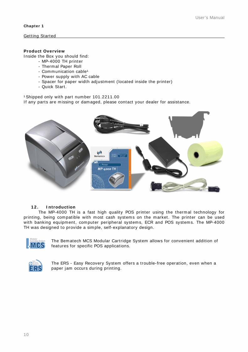
Chapter 1 Getting Started Product Overview Inside the Box you should find: - MP-4000 TH printer - Thermal Paper Roll - Communication cable¹ - Power supply with AC cable - Spacer for paper width adjustment (located inside the printer) - Quick Start. ¹Shipped only with part number 101.2211.00 If any parts are missing or damaged, please contact your dealer for assistance.
12. Introduction The MP-4000 TH is a fast high quality POS printer using the thermal technology for printing, being compatible with most cash systems on the market. The printer can be used with banking equipment, computer peripheral systems, ECR and POS systems. The MP-4000 TH was designed to provide a simple, self-explanatory design.
The Bematech MCS Modular Cartridge System allows for convenient addition of features for specific POS applications.
The ERS - Easy Recovery System offers a trouble-free operation, even when a paper jam occurs during printing.
MP-4000 TH . Revision 1.3
11
The printer has the following main features.
13. Product Characteristics - High-speed printing mode up to 250 mm/s - Silent thermal printing - Paper Feed Speed of 59 lps - Dot Density of 8 dots/mm (203 dpi x 203 dpi) - Selectable font types (more than 9 types to choose) - Easy drop-in paper roll loading - Multiple sizes of paper rolls are possible
Selectable Paper width from 58 mm to 82.5 mm Paper diameter up to 102 mm
- Support to partial and full paper-cut - Easy cover opening through an easily accessible top-cover lever - Optional interfaces:
Serial RS232 DB25; Serial RS232 DB9; Parallel IEEE1284; Ethernet 10/100; USB 2.0;
- Extended reliability (150 km print head life and 2 million cuts of cutter life)
14. Software and Drivers - Extended options for barcode printing are possible (EAN-8, EAN-13, CODE 93, CODE129, ITF, CODABAR, UPC-A, UPC-E, ISBN, MSI, PLESSEY, PDF-417) - Complete drivers for Windows including Spooler Driver, APIs. - Easy configuration and remote management by Bematech User Utility Software application - Bitmap Image Buffer, for uploading logos to the printer’s internal non-volatile memory - Different sizes of characters and code pages - ESC/POSTM Command Emulation EPSON and ESC/POSTM are registered trademarks of SEIKO EPSON Corporation. Windows and Windows NT are registered trademarks of Microsoft Corporation in the United States and/or other countries. Company and product names are trademarks or registered trademarks of their respective companies.
15. Typical Applications - General receipt printing - Restaurants - Gas Stations - Fast food systems - Banks - Drugstores - Supermarkets
16. Description of Models The MP-4000 TH is available in the following models: MP-4000 TH with RS-232 Serial Interface (DB9 connector); MP-4000 TH with RS-232 Serial Interface (DB25 connector); MP-4000 TH with IEEE1284 Parallel Interface; MP-4000 TH with USB 2.0 Interface; MP-4000 TH with Ethernet Interface. * Please contact Bematech or your Retailer for the availability of other product colors. * Please contact Bematech or your Retailer for the availability of interfaces.

User’s Manual
12
Bematech products used with this product: Smart Box 2000 Smart Box 5000 Bematech Cash Drawer * Please visit Bematech website for more information about these products.
www.bematech.com
17. Optional Items and Accessories IEEE1284 Parallel Interface RS-232 Serial Interface (DB25 connector) RS-232 Serial Interface (DB9 connector) USB Interface Ethernet Interface * Please contact Bematech or your Retailer for the availability of interfaces and accessories.
MP-4000 TH . Revision 1.3
13
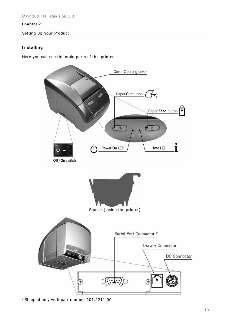
Chapter 2 Setting Up Your Product Installing Here you can see the main parts of this printer.
Spacer (inside the printer)
*Shipped only with part number 101.2211.00
User’s Manual
14
Where to place the printer
WARNING! The MP-4000 TH should be placed on a plain, stable surface located indoors or protected from the weather. Avoid enclosing the printer or keeping it obstructed. Connections It is possible to connect up to three cables to the printer. All connections are placed at the back of the printer (there can be different connections depending on the configuration of the Printer Interface Board).
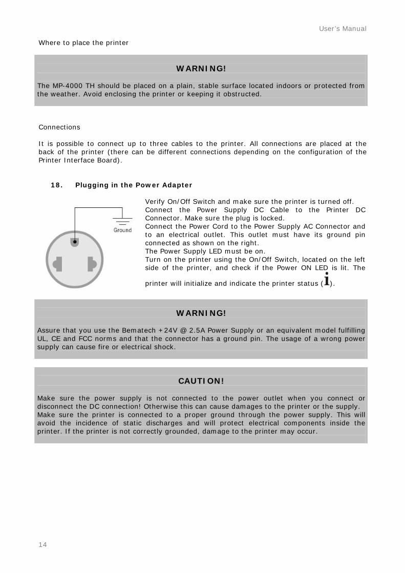
18. Plugging in the Power Adapter
Verify On/Off Switch and make sure the printer is turned off. Connect the Power Supply DC Cable to the Printer DC Connector. Make sure the plug is locked. Connect the Power Cord to the Power Supply AC Connector and to an electrical outlet. This outlet must have its ground pin connected as shown on the right. The Power Supply LED must be on. Turn on the printer using the On/Off Switch, located on the left side of the printer, and check if the Power ON LED is lit. The
printer will initialize and indicate the printer status (
).
WARNING! Assure that you use the Bematech +24V @ 2.5A Power Supply or an equivalent model fulfilling UL, CE and FCC norms and that the connector has a ground pin. The usage of a wrong power supply can cause fire or electrical shock.
CAUTION! Make sure the power supply is not connected to the power outlet when you connect or disconnect the DC connection! Otherwise this can cause damages to the printer or the supply. Make sure the printer is connected to a proper ground through the power supply. This will avoid the incidence of static discharges and will protect electrical components inside the printer. If the printer is not correctly grounded, damage to the printer may occur.
MP-4000 TH . Revision 1.3
15
19. Turn on Your Product Turn on the printer using the On/Off Switch, located on the left side of the printer, and check if
the Power ON LED is lit. The printer will initialize and indicate the printer status ( ).
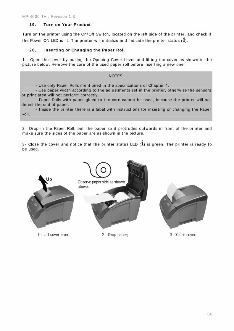
20. Inserting or Changing the Paper Roll
1 - Open the cover by pulling the Opening Cover Lever and lifting the cover as shown in the picture below. Remove the core of the used paper roll before inserting a new one.
NOTES! - Use only Paper Rolls mentioned in the specifications of Chapter 4. - Use paper width according to the adjustments set in the printer, otherwise the sensors or print area will not perform correctly. - Paper Rolls with paper glued to the core cannot be used, because the printer will not detect the end of paper. - Inside the printer there is a label with instructions for inserting or changing the Paper Roll. 2– Drop in the Paper Roll, pull the paper so it protrudes outwards in front of the printer and make sure the sides of the paper are as shown in the picture.
3- Close the cover and notice that the printer status LED ( ) is green. The printer is ready to
be used.
User’s Manual
16
21. Connecting the Communication Cables Verify the Communication Interfaces that you use and follow the right instructions.
21.1. Cash Drawer Connection Verify On/Off Switch and make sure the printer is turned off.
WARNING! The printer is configured by factory default to work with Bematech and EPSON Cash Drawers. The printer configuration is usually compatible with many Cash Drawers in the market. If you are not sure of this compatibility, do not connect the cash drawer cable and verify the printer’s configuration to accept your Cash Drawer. A wrong configuration may damage the printer and the cash drawer as well. Check the manual section “Configuring the Cash Drawer” to make the right configuration.
CAUTION! Never connect a telephone line to the Cash Drawer Connector. Wrong usage may damage the telephone line and the printer. Once you have the right Printer Cash Drawer configuration, make sure the Cash Drawer Cable Connector complies with the RJ12 standard. Connect the Cash Drawer Cable to the Printer’s Drawer Connector. Make sure the plug is locked. Turn on the printer using the On/Off Switch, located on the left side of the printer, and check if
the Power ON LED is lit. The printer will initialize and indicate the printer status ( ).
21.2. Connection of the communication Interface boards Verify On/Off Switch and make sure the printer is turned off. You will need a compatible interface cable fitting your configuration! For the standard configuration follow these steps: Connect the communication Cable to the Printer’s communication Port Connector and to the communication Port of the host system (PC or Microterminal). After connecting the cables, tighten the screws on both sides of the cable (printer and host). Turn on the printer using the On/Off Switch, located on the left side of the printer, and check if
the Power ON LED is lit. The printer will initialize and indicate the printer status ( ).
MP-4000 TH . Revision 1.3
17
Configuring The printer is set up by factory default for most users. For those who need a special configuration, the MP-4000 TH offers various settings. These options can be modified through the Printer’s menu. Several settings can be changed in the Printer Menu. The Printer Menu is self-explanatory. To enter the Printer Menu you have to switch off the
printer and switch on again with the FEED BUTTON ( ) pressed. When it starts to print you
can release the Feed button ( ).
… - Wait to start Self-Test - Press ‘FEED’ switch 1x for CONFIG MODE - Press ‘FEED’ switch 2x for DUMP MODE
After printing the menu above:
Press the FEED BUTTON ( ) once and the Configuration of the Printer will be printed.
Press the Feed button ( ) twice to enter the Configuration Mode.
Press the Cut button ( ) to go to the next parameter or wait to exit Configuration Mode. Configuration Mode This mode offers the possibility to change the language, printer density, configuration of Near End Paper Sensor, paper width, Command Set and Print Mode. (¹) The "Paper Width” can be altered only if the "Command Set " is configured as "BEMATECH." To enter the Printer Menu you have to switch off the printer and switch on again with the FEED
BUTTON ( ) pressed. Wait until that the menu is printed release and press the FEED BUTTON
( ) again.
Choose the next parameter by pressing the Cut button ( ), modify the parameter with
the Feed button ( ) and observe the result. To accept the change in the parameter press the Cut button; it will automatically move to the next parameter in the list. The printer will guide you through the options by printing a response after every decision you make. To jump back you have to restart the Configuration Mode and go through the list of parameters.
22. Language Configuration In this section, you can configure the language that the Printer Menus will present to you. You can configure to English, Spanish or Portuguese. The factory default setting is English.
User’s Manual
18
23. Print Density Configuration In this section, you can configure the print density of all printed information. This configuration is very important when you use different paper thicknesses. You can configure to Normal, Strong, Very Strong, Very Weak or Weak Print Density. The factory default setting is Normal.
24. Near End Paper Sensor Configuration In this section, you can configure the ability to use the Near End Paper Sensor. You can disable it to turn off the sensor or enable it to detect the end of paper roll with the sensor and report the status to the host system. You can adjust the paper length at the sensor indication by following the proper steps. The factory default setting is Enable.
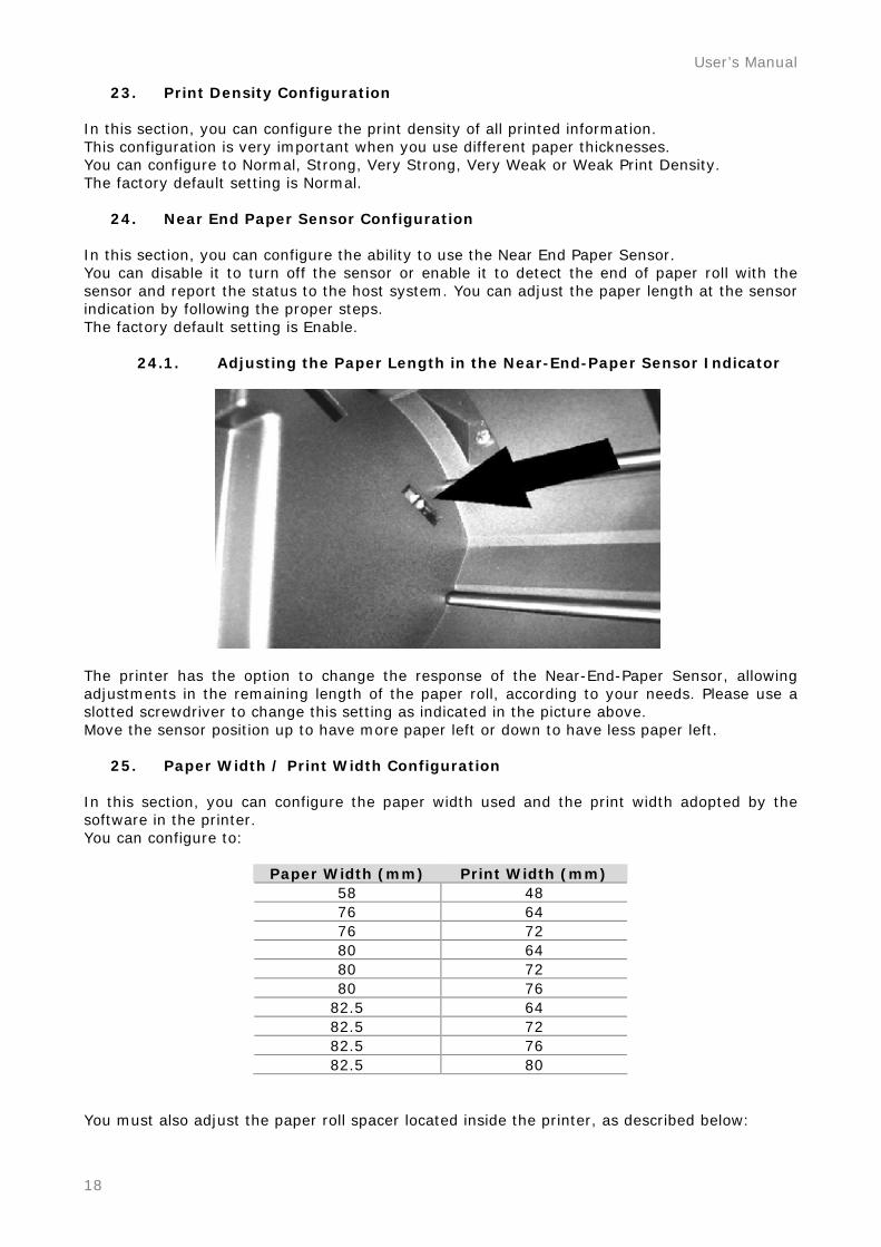
24.1. Adjusting the Paper Length in the Near-End-Paper Sensor Indicator
The printer has the option to change the response of the Near-End-Paper Sensor, allowing adjustments in the remaining length of the paper roll, according to your needs. Please use a slotted screwdriver to change this setting as indicated in the picture above. Move the sensor position up to have more paper left or down to have less paper left.
25. Paper Width / Print Width Configuration In this section, you can configure the paper width used and the print width adopted by the software in the printer. You can configure to:
Paper Width (mm) Print Width (mm) 58 48 76 64 76 72 80 64 80 72 80 76
82.5 64 82.5 72 82.5 76 82.5 80
You must also adjust the paper roll spacer located inside the printer, as described below:
MP-4000 TH . Revision 1.3
19
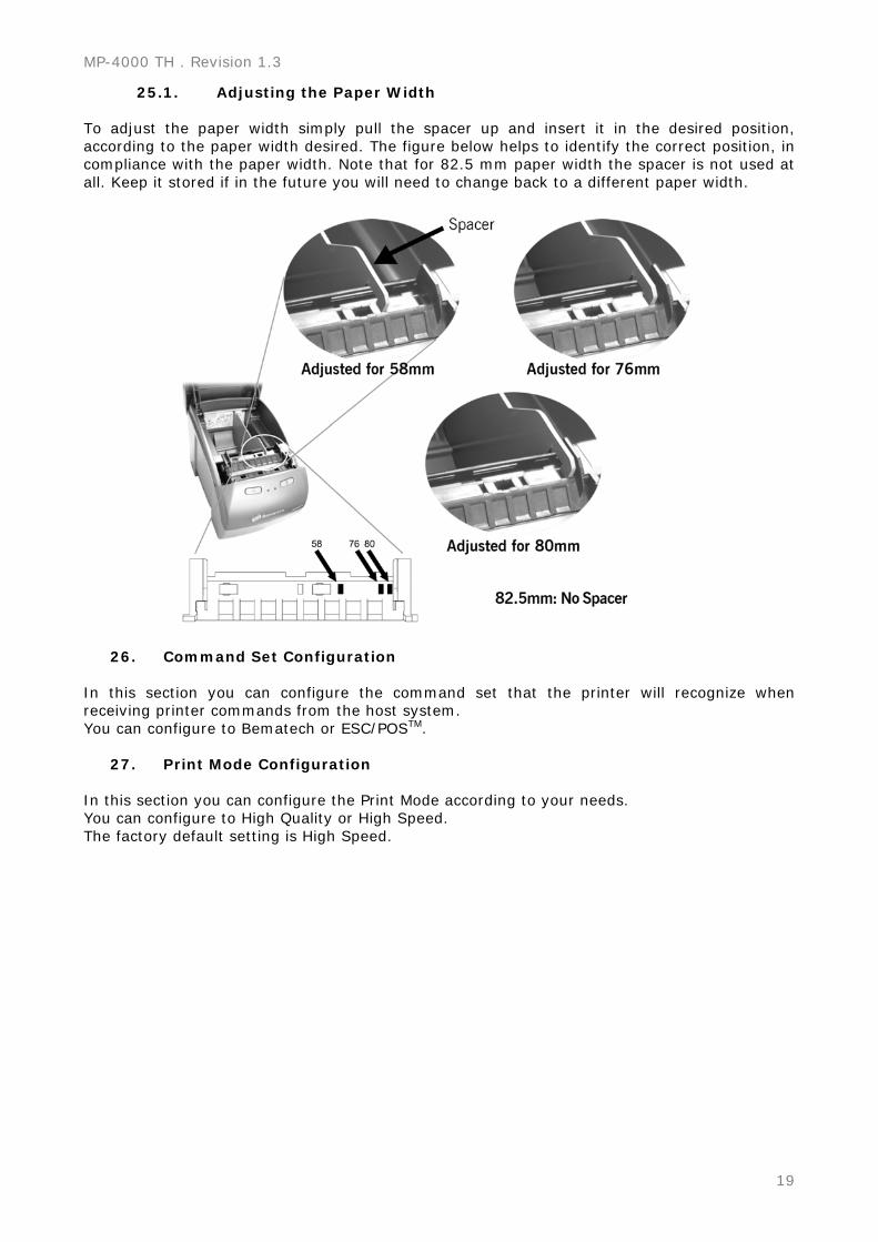
25.1. Adjusting the Paper Width To adjust the paper width simply pull the spacer up and insert it in the desired position, according to the paper width desired. The figure below helps to identify the correct position, in compliance with the paper width. Note that for 82.5 mm paper width the spacer is not used at all. Keep it stored if in the future you will need to change back to a different paper width.
26. Command Set Configuration In this section you can configure the command set that the printer will recognize when receiving printer commands from the host system. You can configure to Bematech or ESC/POSTM.
27. Print Mode Configuration In this section you can configure the Print Mode according to your needs. You can configure to High Quality or High Speed. The factory default setting is High Speed.
User’s Manual
20
Communication Interface Configuration In this section you can configure the Communication Interface.
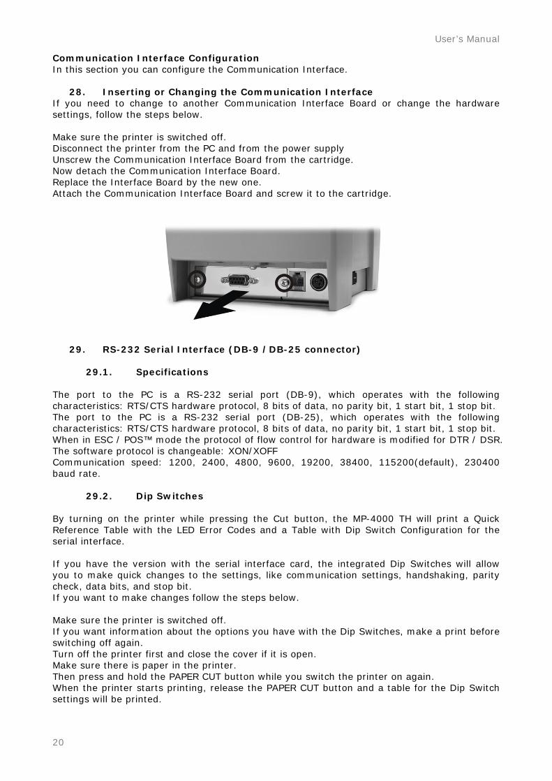
28. Inserting or Changing the Communication Interface If you need to change to another Communication Interface Board or change the hardware settings, follow the steps below. Make sure the printer is switched off. Disconnect the printer from the PC and from the power supply Unscrew the Communication Interface Board from the cartridge. Now detach the Communication Interface Board. Replace the Interface Board by the new one. Attach the Communication Interface Board and screw it to the cartridge.
29. RS-232 Serial Interface (DB-9 /DB-25 connector)
29.1. Specifications The port to the PC is a RS-232 serial port (DB-9), which operates with the following characteristics: RTS/CTS hardware protocol, 8 bits of data, no parity bit, 1 start bit, 1 stop bit. The port to the PC is a RS-232 serial port (DB-25), which operates with the following characteristics: RTS/CTS hardware protocol, 8 bits of data, no parity bit, 1 start bit, 1 stop bit. When in ESC / POS™ mode the protocol of flow control for hardware is modified for DTR / DSR. The software protocol is changeable: XON/XOFF Communication speed: 1200, 2400, 4800, 9600, 19200, 38400, 115200(default), 230400 baud rate.
29.2. Dip Switches By turning on the printer while pressing the Cut button, the MP-4000 TH will print a Quick Reference Table with the LED Error Codes and a Table with Dip Switch Configuration for the serial interface. If you have the version with the serial interface card, the integrated Dip Switches will allow you to make quick changes to the settings, like communication settings, handshaking, parity check, data bits, and stop bit. If you want to make changes follow the steps below. Make sure the printer is switched off. If you want information about the options you have with the Dip Switches, make a print before switching off again. Turn off the printer first and close the cover if it is open. Make sure there is paper in the printer. Then press and hold the PAPER CUT button while you switch the printer on again. When the printer starts printing, release the PAPER CUT button and a table for the Dip Switch settings will be printed.
MP-4000 TH . Revision 1.3
21
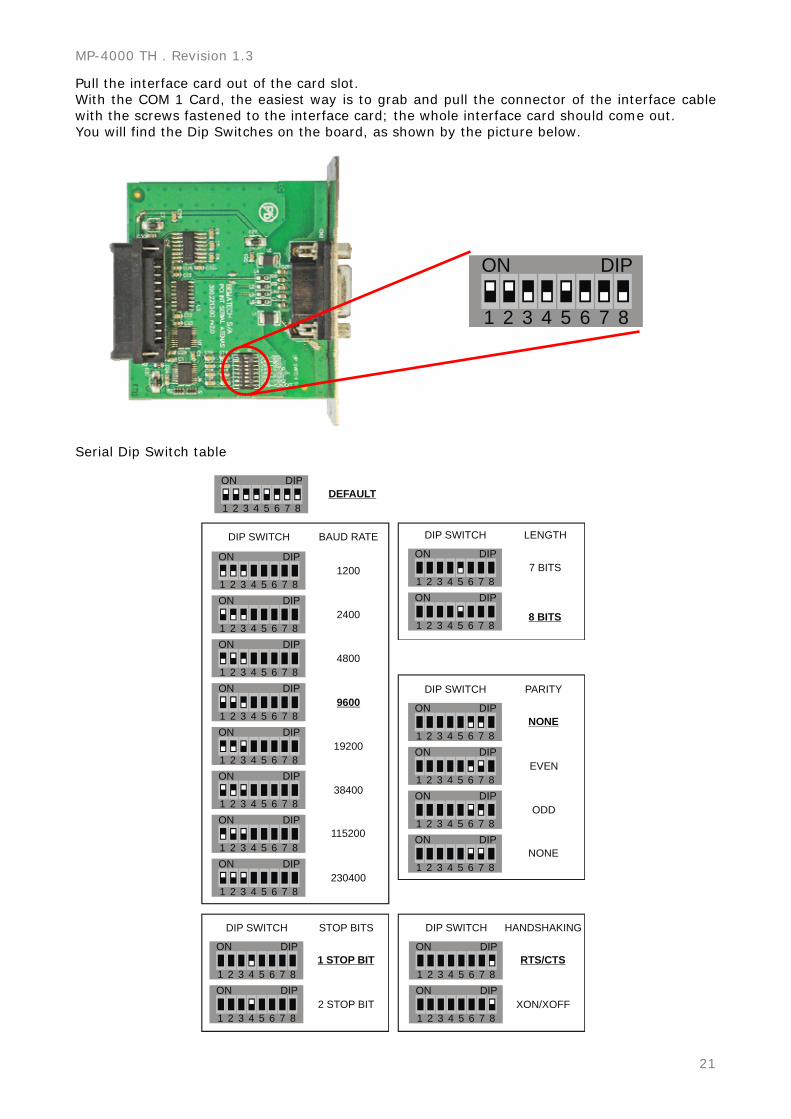
Pull the interface card out of the card slot. With the COM 1 Card, the easiest way is to grab and pull the connector of the interface cable with the screws fastened to the interface card; the whole interface card should come out. You will find the Dip Switches on the board, as shown by the picture below.
1 2 3 4 5 6 7 8
ON DIP
Serial Dip Switch table
1 2 3 4 5 6 7 8
ON DIP
1 2 3 4 5 6 7 8
ON DIP
1 2 3 4 5 6 7 8
ON DIP
1 2 3 4 5 6 7 8
ON DIP
1 2 3 4 5 6 7 8
ON DIP
1 2 3 4 5 6 7 8
ON DIP
1 2 3 4 5 6 7 8
ON DIP
1 2 3 4 5 6 7 8
ON DIP
1 2 3 4 5 6 7 8
ON DIP
1 2 3 4 5 6 7 8
ON DIP
1 2 3 4 5 6 7 8
ON DIP
1 2 3 4 5 6 7 8
ON DIP
1 2 3 4 5 6 7 8
ON DIP
1 2 3 4 5 6 7 8
ON DIP
1 2 3 4 5 6 7 8
ON DIP
1 2 3 4 5 6 7 8
ON DIP
1 2 3 4 5 6 7 8
ON DIP
1 2 3 4 5 6 7 8
ON DIP
1 2 3 4 5 6 7 8
ON DIP
1200
DIP SWITCH BAUD RATE
DIP SWITCH DIP SWITCH HANDSHAKINGSTOP BITS
DIP SWITCH
DIP SWITCH LENGTH
PARITY
DEFAULT
2400
4800
9600
19200
38400
115200
230400
1 STOP BIT
NONE
ODD
EVEN
8 BITS
7 BITS
NONE
RTS/CTS
XON/XOFF2 STOP BIT
User’s Manual
22
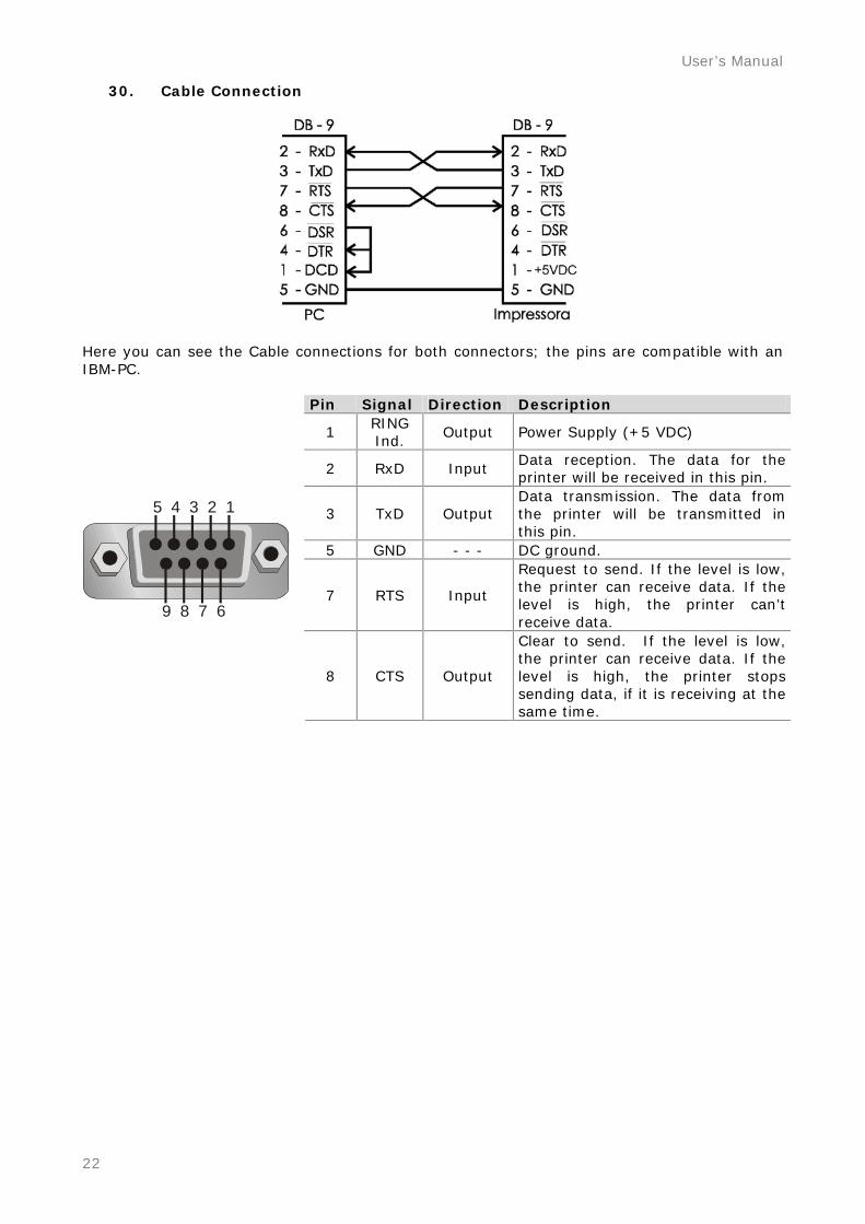
30. Cable Connection
Here you can see the Cable connections for both connectors; the pins are compatible with an IBM-PC.
Pin Signal Direction Description
1 RING Ind.
Output Power Supply (+5 VDC)
2 RxD Input Data reception. The data for the printer will be received in this pin.
3 TxD Output Data transmission. The data from the printer will be transmitted in this pin.
5 GND - - - DC ground.
7 RTS Input
Request to send. If the level is low, the printer can receive data. If the level is high, the printer can’t receive data.
5 4 3 2 1
9 8 7 6
8 CTS Output
Clear to send. If the level is low, the printer can receive data. If the level is high, the printer stops sending data, if it is receiving at the same time.
MP-4000 TH . Revision 1.3
23
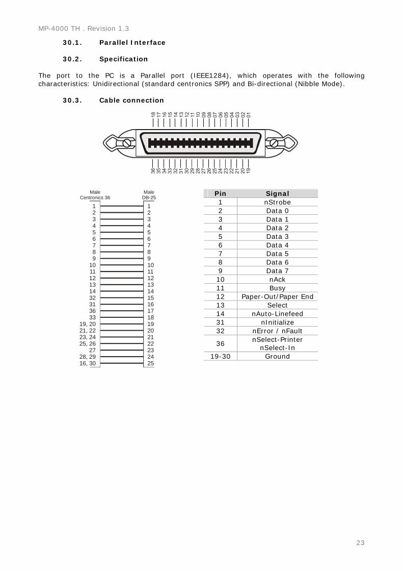
30.1. Parallel Interface
30.2. Specification The port to the PC is a Parallel port (IEEE1284), which operates with the following characteristics: Unidirectional (standard centronics SPP) and Bi-directional (Nibble Mode).
30.3. Cable connection
123456789
101112131432313633
19, 2021, 2223, 2425, 26
2728, 2916, 30
12345678910111213141516171819202122232425
MaleCentronics 36
MaleDB-25
Pin Signal 1 nStrobe 2 Data 0 3 Data 1 4 Data 2 5 Data 3 6 Data 4 7 Data 5 8 Data 6 9 Data 7 10 nAck 11 Busy 12 Paper-Out/Paper End 13 Select 14 nAuto-Linefeed 31 nInitialize 32 nError / nFault
36 nSelect-Printer
nSelect-In 19-30 Ground
User’s Manual
24
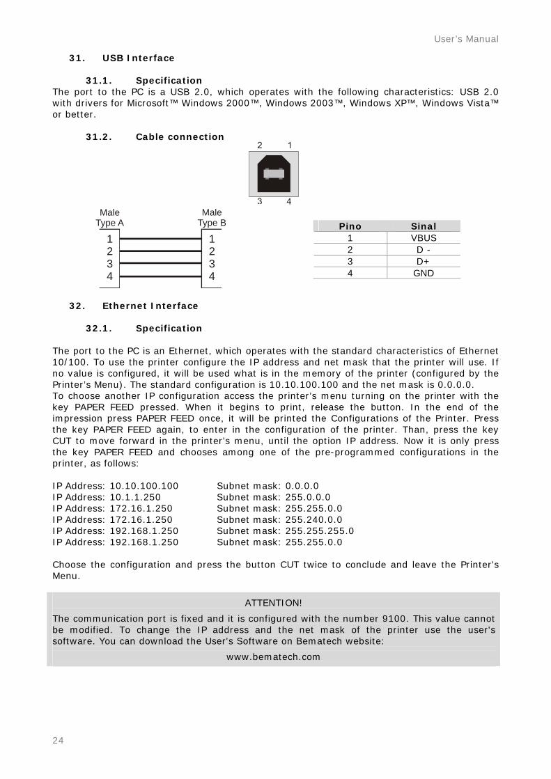
31. USB Interface
31.1. Specification The port to the PC is a USB 2.0, which operates with the following characteristics: USB 2.0 with drivers for Microsoft™ Windows 2000™, Windows 2003™, Windows XP™, Windows Vista™ or better.
31.2. Cable connection
1234
1234
MaleType A
MaleType B
Pino Sinal
1 VBUS 2 D - 3 D+ 4 GND
32. Ethernet Interface
32.1. Specification
The port to the PC is an Ethernet, which operates with the standard characteristics of Ethernet 10/100. To use the printer configure the IP address and net mask that the printer will use. If no value is configured, it will be used what is in the memory of the printer (configured by the Printer’s Menu). The standard configuration is 10.10.100.100 and the net mask is 0.0.0.0. To choose another IP configuration access the printer’s menu turning on the printer with the key PAPER FEED pressed. When it begins to print, release the button. In the end of the impression press PAPER FEED once, it will be printed the Configurations of the Printer. Press the key PAPER FEED again, to enter in the configuration of the printer. Than, press the key CUT to move forward in the printer’s menu, until the option IP address. Now it is only press the key PAPER FEED and chooses among one of the pre-programmed configurations in the printer, as follows: IP Address: 10.10.100.100 Subnet mask: 0.0.0.0 IP Address: 10.1.1.250 Subnet mask: 255.0.0.0 IP Address: 172.16.1.250 Subnet mask: 255.255.0.0 IP Address: 172.16.1.250 Subnet mask: 255.240.0.0 IP Address: 192.168.1.250 Subnet mask: 255.255.255.0 IP Address: 192.168.1.250 Subnet mask: 255.255.0.0 Choose the configuration and press the button CUT twice to conclude and leave the Printer’s Menu.
ATTENTION!
The communication port is fixed and it is configured with the number 9100. This value cannot be modified. To change the IP address and the net mask of the printer use the user's software. You can download the User's Software on Bematech website:
www.bematech.com
MP-4000 TH . Revision 1.3
25
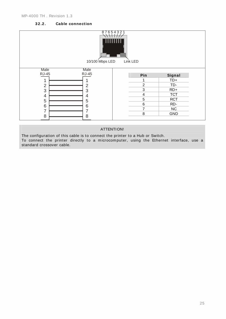
32.2. Cable connection
8 7 6 5 4 3 2 1
10/100 Mbps LED Link LED
12345678
12345678
MaleRJ-45
MaleRJ-45
Pin Signal 1 TD+ 2 TD- 3 RD+ 4 TCT 5 RCT 6 RD- 7 NC 8 GND
ATTENTION!
The configuration of this cable is to connect the printer to a Hub or Switch. To connect the printer directly to a microcomputer, using the Ethernet interface, use a standard crossover cable.
User’s Manual
26
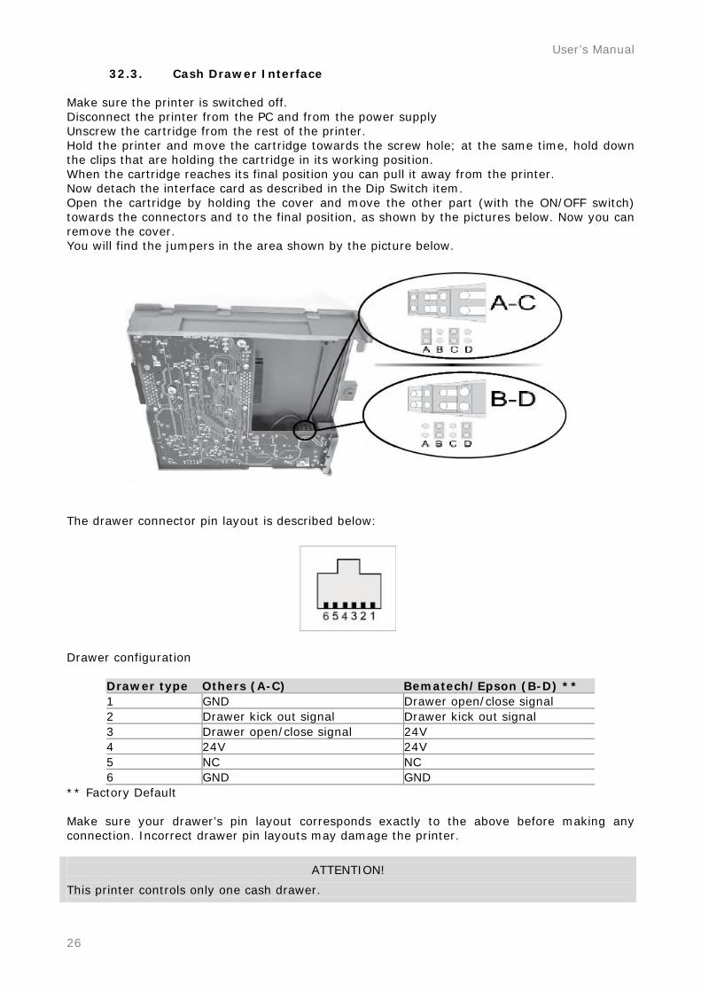
32.3. Cash Drawer Interface Make sure the printer is switched off. Disconnect the printer from the PC and from the power supply Unscrew the cartridge from the rest of the printer. Hold the printer and move the cartridge towards the screw hole; at the same time, hold down the clips that are holding the cartridge in its working position. When the cartridge reaches its final position you can pull it away from the printer. Now detach the interface card as described in the Dip Switch item. Open the cartridge by holding the cover and move the other part (with the ON/OFF switch) towards the connectors and to the final position, as shown by the pictures below. Now you can remove the cover. You will find the jumpers in the area shown by the picture below.
The drawer connector pin layout is described below:
Drawer configuration
Drawer type Others (A-C) Bematech/Epson (B-D) ** 1 GND Drawer open/close signal 2 Drawer kick out signal Drawer kick out signal 3 Drawer open/close signal 24V 4 24V 24V 5 NC NC 6 GND GND
** Factory Default Make sure your drawer’s pin layout corresponds exactly to the above before making any connection. Incorrect drawer pin layouts may damage the printer.
ATTENTION!
This printer controls only one cash drawer.
MP-4000 TH . Revision 1.3
27
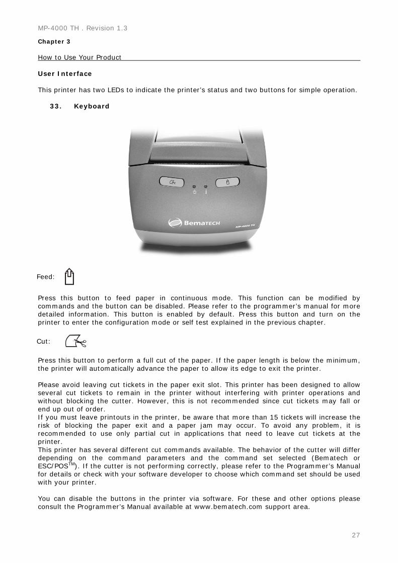
Chapter 3 How to Use Your Product User Interface This printer has two LEDs to indicate the printer’s status and two buttons for simple operation.
33. Keyboard
Feed:
Press this button to feed paper in continuous mode. This function can be modified by commands and the button can be disabled. Please refer to the programmer’s manual for more detailed information. This button is enabled by default. Press this button and turn on the printer to enter the configuration mode or self test explained in the previous chapter.
Cut:
Press this button to perform a full cut of the paper. If the paper length is below the minimum, the printer will automatically advance the paper to allow its edge to exit the printer. Please avoid leaving cut tickets in the paper exit slot. This printer has been designed to allow several cut tickets to remain in the printer without interfering with printer operations and without blocking the cutter. However, this is not recommended since cut tickets may fall or end up out of order. If you must leave printouts in the printer, be aware that more than 15 tickets will increase the risk of blocking the paper exit and a paper jam may occur. To avoid any problem, it is recommended to use only partial cut in applications that need to leave cut tickets at the printer. This printer has several different cut commands available. The behavior of the cutter will differ depending on the command parameters and the command set selected (Bematech or ESC/POSTM). If the cutter is not performing correctly, please refer to the Programmer’s Manual for details or check with your software developer to choose which command set should be used with your printer. You can disable the buttons in the printer via software. For these and other options please consult the Programmer’s Manual available at www.bematech.com support area.
User’s Manual
28
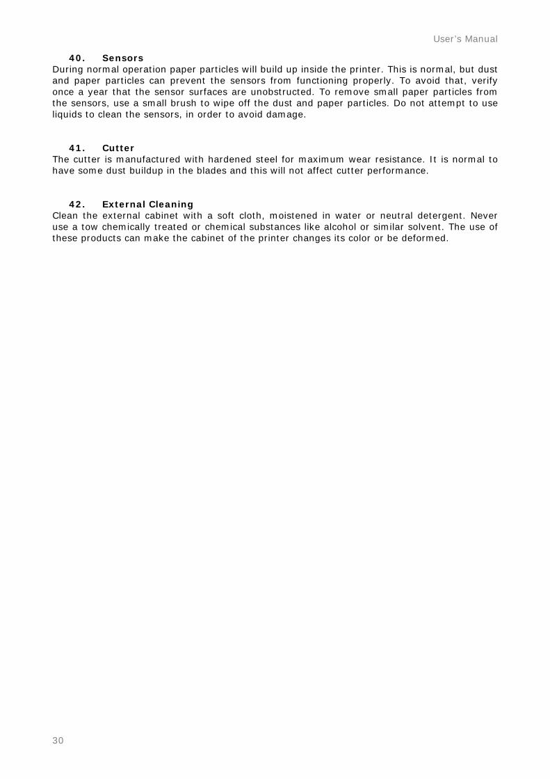
34. LEDs Power LED: This LED is green when the printer is switched on, indicating that the printer is powered correctly.
Info LED:
This LED is used to indicate information on the current printer status. Generally, if it is green your printer is ready to print. If it is yellow you must act to bring the printer back to the ready status. If you come to a situation that this LED is blinking in red, a more serious problem has occurred. Please see the table below for all details. If you need to call for assistance, please remember to check the color and how often this LED is blinking to help sorting out the problem.
Color LED
Status Blinks Meaning - Procedure
ON Ready to Print Green = OK
blinking Ready to print but Near Paper End
ON Cover Open – Close the Cover
blinking No Paper – Insert a New Paper Roll
2 blinks Thermal Print Head Overheating - Wait to Print
3 blinks Cutter Error - Open Cover to Remove Paper Jam (ERS)
Yellow Recoverable Error
4 blinks Communication Error / Command Ignored – Check Programming Mode
1 blink RTOS Error
3 blinks RAM Memory Error
8 blinks Printer Mechanism Error
11 blinks Low DC voltage from Power Supply
Red Unrecoverable
Error
12 blinks Cutter Initialization Error
Operation Modes
35. Normal Mode When you switch on the printer it will run an auto check and light up the green Info LED to indicate that it is ready to use.
36. Other optional modes When you switch on the printer while holding down the Feed button, a menu will be printed to enable choosing several additional operational modes.
36.1. Self Test Mode To start the self test you only have to wait a few seconds without doing anything after you are in the Printer Menu. The printer will print a sample ticket with a list of features of your MP-4000 TH, followed by a full cut.
36.2. Configuration Mode For Configuration Mode go to chapter 2.
MP-4000 TH . Revision 1.3
29
36.3. Dump Mode Press the Feed button twice to enter Dump Mode. The printer will print all data received by the communication interface in hexadecimal format. This is only used by software developers. To exit this mode, switch off the printer and turn it back on. Software
37. Drivers
37.1. API Drivers These drivers have been developed to help software development and reduce its time. Advanced features are ready for use if you are developing for Windows-based systems. Details are given in the help file included in the development kit that can be downloaded from Bematech’s website support section.
37.2. Spooler Drivers Spooler drivers are standard drivers for Windows-based applications that are simple to install. Simply download the driver package from Bematech’s website support area, run the installation package and follow the instructions. Details on driver functions can be accessed in the help file.
38. User Utility Software The User Utility software is a Windows-based application that has several basic and advanced functions for the MP-4000 TH printer. It can be used to test the behavior of several settings in the printer, and to print in many different ways, with different resources; it can also be used to test different settings if a special application requires a fine tuning of the printer. This software has several tools for barcode printing and for logo storage in the printer. When several settings must be reproduced for several printers, a macro option is available to make the configuration task simple and easy. This is simple, intuitive and multilanguage software, specially developed to speed up your installation process. It is also available at Bematech’s website support section. Download the installation package and follow the instructions.
38.1. Firmware Upgrading Upgrading the firmware for the MP-4000 TH is a very simple task with the User Utility Software. You only need to select the firmware binary file and press the download button. The software will check that the printer is communicating correctly and perform the firmware download automatically. This will only be necessary when additional functions are added to the printer for a particular application or when new features are developed for this printer. Preventive Maintenance This printer has been developed to have a long life expectancy with no replacement of components and minimum user interference. But printer lifetime is highly influenced by the following factors: paper quality, regular preventive maintenance, environmental conditions and how carefully the user handles this product.
39. Print Head
CAUTION! The print head can be hot just after printing. Do not touch the print head; let it cool down before touching and cleaning. Because the thermal elements of the print head and driver IC are fragile, avoid touching them with any metal objects or any abrasive material. During normal operation some ink particles from the thermal paper will adhere to the thermal print head surface. Therefore, it is recommended to clean the printer head after 10 km of printed length or if printing quality is degrading. Switch off the printer before cleaning it. Clean the print head with a cotton swab, soaked with alcohol solvent (ethanol or isopropanol). Do not clean the print head with hard, abrasive objects or your fingers, since this can cause damage to its delicate surface. Clean the platen roller (rubber roller) with the cotton swab to remove any dust particles.
User’s Manual
30
40. Sensors During normal operation paper particles will build up inside the printer. This is normal, but dust and paper particles can prevent the sensors from functioning properly. To avoid that, verify once a year that the sensor surfaces are unobstructed. To remove small paper particles from the sensors, use a small brush to wipe off the dust and paper particles. Do not attempt to use liquids to clean the sensors, in order to avoid damage.
41. Cutter The cutter is manufactured with hardened steel for maximum wear resistance. It is normal to have some dust buildup in the blades and this will not affect cutter performance.
42. External Cleaning Clean the external cabinet with a soft cloth, moistened in water or neutral detergent. Never use a tow chemically treated or chemical substances like alcohol or similar solvent. The use of these products can make the cabinet of the printer changes its color or be deformed.
MP-4000 TH . Revision 1.3
31
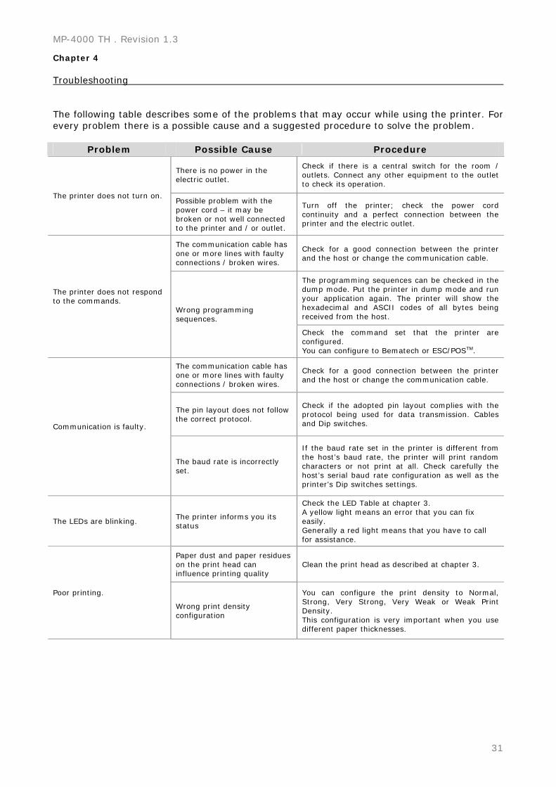
Chapter 4 Troubleshooting The following table describes some of the problems that may occur while using the printer. For every problem there is a possible cause and a suggested procedure to solve the problem.
Problem Possible Cause Procedure
There is no power in the electric outlet.
Check if there is a central switch for the room / outlets. Connect any other equipment to the outlet to check its operation.
The printer does not turn on. Possible problem with the power cord – it may be broken or not well connected to the printer and / or outlet.
Turn off the printer; check the power cord continuity and a perfect connection between the printer and the electric outlet.
The communication cable has one or more lines with faulty connections / broken wires.
Check for a good connection between the printer and the host or change the communication cable.
The programming sequences can be checked in the dump mode. Put the printer in dump mode and run your application again. The printer will show the hexadecimal and ASCII codes of all bytes being received from the host.
The printer does not respond to the commands.
Wrong programming sequences.
Check the command set that the printer are configured. You can configure to Bematech or ESC/POSTM.
The communication cable has one or more lines with faulty connections / broken wires.
Check for a good connection between the printer and the host or change the communication cable.
The pin layout does not follow the correct protocol.
Check if the adopted pin layout complies with the protocol being used for data transmission. Cables and Dip switches. Communication is faulty.
The baud rate is incorrectly set.
If the baud rate set in the printer is different from the host’s baud rate, the printer will print random characters or not print at all. Check carefully the host’s serial baud rate configuration as well as the printer’s Dip switches settings.
The LEDs are blinking. The printer informs you its status
Check the LED Table at chapter 3. A yellow light means an error that you can fix easily. Generally a red light means that you have to call for assistance.
Paper dust and paper residues on the print head can influence printing quality
Clean the print head as described at chapter 3.
Poor printing.
Wrong print density configuration
You can configure the print density to Normal, Strong, Very Strong, Very Weak or Weak Print Density. This configuration is very important when you use different paper thicknesses.
User’s Manual
32
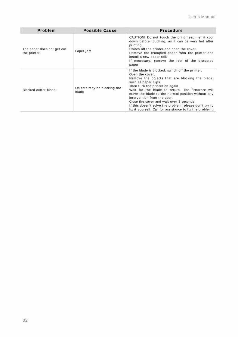
Problem Possible Cause Procedure
The paper does not get out the printer.
Paper jam
CAUTION! Do not touch the print head; let it cool down before touching, as it can be very hot after printing. Switch off the printer and open the cover. Remove the crumpled paper from the printer and install a new paper roll. If necessary, remove the rest of the disrupted paper.
Blocked cutter blade. Objects may be blocking the blade
If the blade is blocked, switch off the printer. Open the cover. Remove the objects that are blocking the blade, such as paper clips. Then turn the printer on again. Wait for the blade to return. The firmware will move the blade to the normal position without any intervention from the user. Close the cover and wait over 3 seconds. If this doesn’t solve the problem, please don’t try to fix it yourself. Call for assistance to fix the problem.
MP-4000 TH . Revision 1.3
33
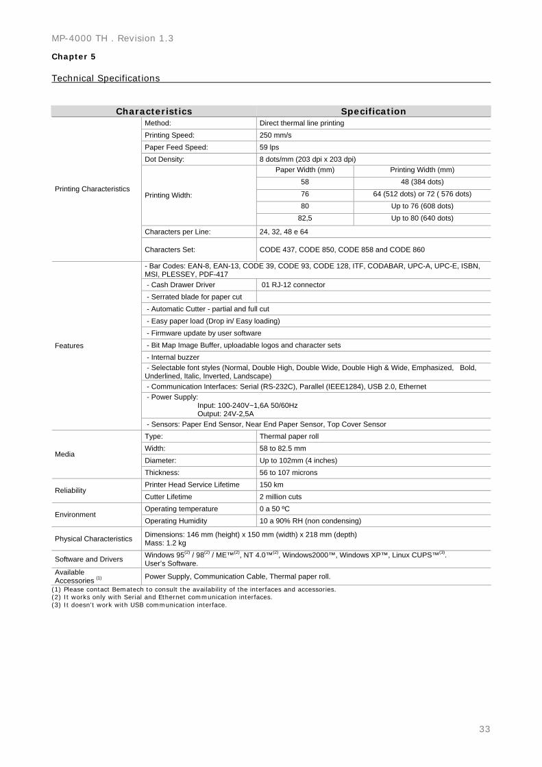
Chapter 5 Technical Specifications
Characteristics Specification Method: Direct thermal line printing Printing Speed: 250 mm/s Paper Feed Speed: 59 lps Dot Density: 8 dots/mm (203 dpi x 203 dpi)
Paper Width (mm) Printing Width (mm) 58 48 (384 dots) 76 64 (512 dots) or 72 ( 576 dots) 80 Up to 76 (608 dots)
Printing Width:
82,5 Up to 80 (640 dots)
Characters per Line: 24, 32, 48 e 64
Printing Characteristics
Characters Set: CODE 437, CODE 850, CODE 858 and CODE 860
- Bar Codes: EAN-8, EAN-13, CODE 39, CODE 93, CODE 128, ITF, CODABAR, UPC-A, UPC-E, ISBN, MSI, PLESSEY, PDF-417 - Cash Drawer Driver 01 RJ-12 connector - Serrated blade for paper cut - Automatic Cutter - partial and full cut - Easy paper load (Drop in/ Easy loading) - Firmware update by user software - Bit Map Image Buffer, uploadable logos and character sets - Internal buzzer - Selectable font styles (Normal, Double High, Double Wide, Double High & Wide, Emphasized, Bold, Underlined, Italic, Inverted, Landscape) - Communication Interfaces: Serial (RS-232C), Parallel (IEEE1284), USB 2.0, Ethernet - Power Supply: Input: 100-240V~1,6A 50/60Hz Output: 24V-2,5A
Features
- Sensors: Paper End Sensor, Near End Paper Sensor, Top Cover Sensor Type: Thermal paper roll Width: 58 to 82.5 mm Diameter: Up to 102mm (4 inches)
Media
Thickness: 56 to 107 microns Printer Head Service Lifetime 150 km
Reliability Cutter Lifetime 2 million cuts Operating temperature 0 a 50 ºC
Environment Operating Humidity 10 a 90% RH (non condensing)
Physical Characteristics Dimensions: 146 mm (height) x 150 mm (width) x 218 mm (depth) Mass: 1.2 kg
Software and Drivers Windows 95(2) / 98(2) / ME™(2), NT 4.0™(2), Windows2000™, Windows XP™, Linux CUPS™(3). User’s Software.
Available Accessories (1) Power Supply, Communication Cable, Thermal paper roll.
(1) Please contact Bematech to consult the availability of the interfaces and accessories. (2) It works only with Serial and Ethernet communication interfaces. (3) It doesn't work with USB communication interface.