![Review Article A Review of Computational Electromagnetic ...et al. [ ] used metamaterial made up of periodic graphene microribbon arrays for terahertz plasmon excitations and demonstrated](https://static.fdocuments.in/doc/165x107/60bf77d5262f570c1e13764b/review-article-a-review-of-computational-electromagnetic-et-al-used-metamaterial.jpg)
Manipulating the plasmon-induced transparency in terahertz metamaterials
8
Manipulating the plasmon-induced transparency in terahertz metamaterials Zhongyang Li, 1 Yingfang Ma, 1 Ran Huang, 2 Ranjan Singh, 2,3 Jianqiang Gu, 1 Zhen Tian, 1 Jiaguang Han, 1,4 and Weili Zhang 1,2,5 1 Center for Terahertz Waves and College of Precision Instrument and Optoelectronics Engineering, Key Laboratory of Opto-Electronics Information and Technical Science, Ministry of Education, Tianjin University, China 2 School of Electrical and Computer Engineering, Oklahoma State University, Stillwater, Oklahoma 74078, USA 3 Center for Integrated Nanotechnologies, Materials Physics and Applications Division, Los Alamos National Laboratory, Los Alamos, New Mexico 87545, USA 4 [email protected] 5 [email protected] Abstract: Coupling between superradiant and subradiant mode resonators in a metamaterial unit cell plays an important role in observing the sharp transparency peak due to destructive interference between the resonators. This effect is enhanced as the resonators are brought closer to each other in a conventional planar arrangement. We present a novel coupling scheme of planar terahertz metamaterial to tune the plasmon-induced transparency peak by physically varying the distance between the superradiant and the subradiant resonators in such a way that the transparency peak begins to disappear as the coupled resonators are brought closer than a critical separation distance. The effect is attributed to the disappearance of the resonant behavior of the subradiant resonator in a closely coupled regime. The simple planar design presented here demonstrates a scheme to manipulate the electromagnetically induced transparency-like behavior in terahertz metamaterials and this could lead to the development of unique slow light devices for terahertz applications. © 2011 Optical Society of America OCIS codes: (160.3918) Metamaterials; (240.6680) Surface plasmons. References and links 1. S. E. Harris, “Electromagnetically induced transparency,” Phys. Today 50(7), 36–42 (1997). 2. T. F. Krauss, “Why do we need slow light,” Nat. Photonics 2(8), 448–450 (2008). 3. M. Fleischhauer, A. Imamoglu, and J. P. Marangos, “Electromagnetically induced transparency: optics in coherent media,” Rev. Mod. Phys. 77(2), 633–673 (2005). 4. N. Papasimakis, V. A. Fedotov, N. I. Zheludev, and S. L. Prosvirnin, “Metamaterial analog of electromagnetically induced transparency,” Phys. Rev. Lett. 101(25), 253903 (2008). 5. S. Zhang, D. A. Genov, Y. Wang, M. Liu, and X. Zhang, “Plasmon-induced transparency in metamaterials,” Phys. Rev. Lett. 101(4), 047401 (2008). 6. R. Singh, C. Rockstuhl, F. Lederer, and W. Zhang, “Coupling between a dark and a bright eigenmode in a terahertz metamaterial,” Phys. Rev. B 79(8), 085111 (2009). 7. P. Tassin, L. Zhang, T. Koschny, E. N. Economou, and C. M. Soukoulis, “Low-loss metamaterials based on classical electromagnetically induced transparency,” Phys. Rev. Lett. 102(5), 053901 (2009). 8. S.-Y. Chiam, R. Singh, C. Rockstuhl, F. Lederer, W. Zhang, and A. Bettiol, “Analogue of electromagnetically induced transparency in a terahertz metamaterial,” Phys. Rev. B 80(15), 153103 (2009). 9. N. Liu, L. Langguth, T. Weiss, J. Kästel, M. Fleischhauer, T. Pfau, and H. Giessen, “Plasmonic analogue of electromagnetically induced transparency at the Drude damping limit ,” Nat. Mater. 8(9), 758–762 (2009). 10. C.-Y. Chen, I.-W. Un, N.-H. Tai, and T.-J. Yen, “Asymmetric coupling between subradiant and superradiant plasmonic resonances and its enhanced sensing performance,” Opt. Express 17(17), 15372–15380 (2009). 11. A. Christ, O. J. F. Martin, Y. Ekinci, N. A. Gippius, and S. G. Tikhodeev, “Symmetry breaking in a plasmonic metamaterial at optical wavelength,” Nano Lett. 8(8), 2171–2175 (2008). 12. V. A. Fedotov, M. Rose, S. L. Prosvirnin, N. Papasimakis, and N. I. Zheludev, “Sharp trapped-mode resonances in planar metamaterials with a broken structural symmetry,” Phys. Rev. Lett. 99(14), 147401 (2007). 13. C. L. Garrido Alzar, M. A. G. Martinez, and P. Nussenzveig, “Classical analog of electromagnetically induced transparency,” Am. J. Phys. 70(1), 37–41 (2002). #143073 - $15.00 USD Received 22 Feb 2011; revised 8 Apr 2011; accepted 18 Apr 2011; published 22 Apr 2011 (C) 2011 OSA 25 April 2011 / Vol. 19, No. 9 / OPTICS EXPRESS 8912
Transcript of Manipulating the plasmon-induced transparency in terahertz metamaterials

Manipulating the plasmon-induced transparency
in terahertz metamaterials
Zhongyang Li,1 Yingfang Ma,
1 Ran Huang,
2 Ranjan Singh,
2,3 Jianqiang Gu,
1 Zhen
Tian,1 Jiaguang Han,
1,4 and Weili Zhang
1,2,5
1Center for Terahertz Waves and College of Precision Instrument and Optoelectronics Engineering, Key Laboratory
of Opto-Electronics Information and Technical Science, Ministry of Education, Tianjin University, China 2School of Electrical and Computer Engineering, Oklahoma State University, Stillwater, Oklahoma 74078, USA
3Center for Integrated Nanotechnologies, Materials Physics and Applications Division, Los Alamos National
Laboratory, Los Alamos, New Mexico 87545, USA [email protected]
Abstract: Coupling between superradiant and subradiant mode resonators
in a metamaterial unit cell plays an important role in observing the sharp
transparency peak due to destructive interference between the resonators.
This effect is enhanced as the resonators are brought closer to each other in
a conventional planar arrangement. We present a novel coupling scheme of
planar terahertz metamaterial to tune the plasmon-induced transparency
peak by physically varying the distance between the superradiant and the
subradiant resonators in such a way that the transparency peak begins to
disappear as the coupled resonators are brought closer than a critical
separation distance. The effect is attributed to the disappearance of the
resonant behavior of the subradiant resonator in a closely coupled regime.
The simple planar design presented here demonstrates a scheme to
manipulate the electromagnetically induced transparency-like behavior in
terahertz metamaterials and this could lead to the development of unique
slow light devices for terahertz applications.
© 2011 Optical Society of America
OCIS codes: (160.3918) Metamaterials; (240.6680) Surface plasmons.
References and links
1. S. E. Harris, “Electromagnetically induced transparency,” Phys. Today 50(7), 36–42 (1997).
2. T. F. Krauss, “Why do we need slow light,” Nat. Photonics 2(8), 448–450 (2008). 3. M. Fleischhauer, A. Imamoglu, and J. P. Marangos, “Electromagnetically induced transparency: optics in
coherent media,” Rev. Mod. Phys. 77(2), 633–673 (2005). 4. N. Papasimakis, V. A. Fedotov, N. I. Zheludev, and S. L. Prosvirnin, “Metamaterial analog of
electromagnetically induced transparency,” Phys. Rev. Lett. 101(25), 253903 (2008).
5. S. Zhang, D. A. Genov, Y. Wang, M. Liu, and X. Zhang, “Plasmon-induced transparency in metamaterials,” Phys. Rev. Lett. 101(4), 047401 (2008).
6. R. Singh, C. Rockstuhl, F. Lederer, and W. Zhang, “Coupling between a dark and a bright eigenmode in a
terahertz metamaterial,” Phys. Rev. B 79(8), 085111 (2009). 7. P. Tassin, L. Zhang, T. Koschny, E. N. Economou, and C. M. Soukoulis, “Low-loss metamaterials based on
classical electromagnetically induced transparency,” Phys. Rev. Lett. 102(5), 053901 (2009).
8. S.-Y. Chiam, R. Singh, C. Rockstuhl, F. Lederer, W. Zhang, and A. Bettiol, “Analogue of electromagnetically induced transparency in a terahertz metamaterial,” Phys. Rev. B 80(15), 153103 (2009).
9. N. Liu, L. Langguth, T. Weiss, J. Kästel, M. Fleischhauer, T. Pfau, and H. Giessen, “Plasmonic analogue of
electromagnetically induced transparency at the Drude damping limit,” Nat. Mater. 8(9), 758–762 (2009). 10. C.-Y. Chen, I.-W. Un, N.-H. Tai, and T.-J. Yen, “Asymmetric coupling between subradiant and superradiant
plasmonic resonances and its enhanced sensing performance,” Opt. Express 17(17), 15372–15380 (2009).
11. A. Christ, O. J. F. Martin, Y. Ekinci, N. A. Gippius, and S. G. Tikhodeev, “Symmetry breaking in a plasmonic metamaterial at optical wavelength,” Nano Lett. 8(8), 2171–2175 (2008).
12. V. A. Fedotov, M. Rose, S. L. Prosvirnin, N. Papasimakis, and N. I. Zheludev, “Sharp trapped-mode resonances
in planar metamaterials with a broken structural symmetry,” Phys. Rev. Lett. 99(14), 147401 (2007). 13. C. L. Garrido Alzar, M. A. G. Martinez, and P. Nussenzveig, “Classical analog of electromagnetically induced
transparency,” Am. J. Phys. 70(1), 37–41 (2002).
#143073 - $15.00 USD Received 22 Feb 2011; revised 8 Apr 2011; accepted 18 Apr 2011; published 22 Apr 2011(C) 2011 OSA 25 April 2011 / Vol. 19, No. 9 / OPTICS EXPRESS 8912

14. R. Singh, I. A. I. Al-Naib, M. Koch, and W. Zhang, “Sharp Fano resonances in THz metamaterials,” Opt.
Express 19(7), 6312–6319 (2011). 15. J. Zhang, S. Xiao, C. Jeppesen, A. Kristensen, and N. A. Mortensen, “Electromagnetically induced transparency
in metamaterials at near-infrared frequency,” Opt. Express 18(16), 17187–17192 (2010).
16. H. A. Haus, Waves and Fields in Optoelectronics (Prentice Hall, 1983). 17. Q. Bai, C. Liu, J. Chen, C. Cheng, M. Kang, and H.-T. Wang, “Tunable slow light in semiconductor
metamaterial in a broad terahertz regime,” J. Appl. Phys. 107(9), 093104 (2010).
18. V. Yannopapas, E. Paspalakis, and N. V. Vitanov, “Electromagnetically induced transparency and slow light in an array of metallic nanoparticles,” Phys. Rev. B 80(3), 035104 (2009).
19. N. Papasimakis, Y. H. Fu, V. A. Fedotov, S. L. Prosvirnin, D. P. Tsai, and N. I. Zheludev, “Metamaterial with
polarization and direction insensitive resonant transmission response mimicking electromagnetically induced transparency,” Appl. Phys. Lett. 94(21), 211902 (2009).
20. Y. Lu, X. Jin, H. Zheng, Y. P. Lee, J. Y. Rhee, and W. H. Jang, “Plasmonic electromagnetically-induced
transparency in symmetric structures,” Opt. Express 18(13), 13396–13401 (2010). 21. Y. Lu, J. Y. Rhee, W. H. Jang, and Y. P. Lee, “Active manipulation of plasmonic electromagnetically-induced
transparency based on magnetic plasmon resonance,” Opt. Express 18(20), 20912–20917 (2010).
22. R. D. Kekatpure, E. S. Barnard, W. Cai, and M. L. Brongersma, “Phase-coupled plasmon-induced transparency,” Phys. Rev. Lett. 104(24), 243902 (2010).
23. B. Luk’yanchuk, N. I. Zheludev, S. A. Maier, N. J. Halas, P. Nordlander, H. Giessen, and C. T. Chong, “The
Fano resonance in plasmonic nanostructures and metamaterials,” Nat. Mater. 9(9), 707–715 (2010). 24. R. Singh, A. K. Azad, J. F. O’Hara, A. J. Taylor, and W. Zhang, “Effect of metal permittivity on resonant
properties of terahertz metamaterials,” Opt. Lett. 33(13), 1506–1508 (2008).
25. A. K. Azad, J. Dai, and W. Zhang, “Transmission properties of terahertz pulses through subwavelength double split-ring resonators,” Opt. Lett. 31(5), 634–636 (2006).
26. R. Singh, C. Rockstuhl, F. Lederer, and W. Zhang, “The impact of nearest neighbor interaction on the resonances
in terahertz metamaterials,” Appl. Phys. Lett. 94(2), 021116 (2009). 27. P. Tassin, L. Zhang, T. Koschny, E. N. Economou, and C. M. Soukoulis, “Planar designs for electromagnetically
induced transparency in metamaterials,” Opt. Express 17(7), 5595–5605 (2009). 28. K. L. Tsakmakidis, M. S. Wartak, J. J. H. Cook, J. M. Hamm, and O. Hess, “Negative-permeability
electromagnetically induced transparent and magnetically active metamaterials,” Phys. Rev. B 81(19), 195128
(2010). 29. R. Singh, C. Rockstuhl, and W. Zhang, “Strong influence of packing density in terahertz metamaterials,” Appl.
Phys. Lett. 97(24), 241108 (2010).
1. Introduction
Electromagnetic induced transparency (EIT) is an appealing physical phenomenon where the
otherwise opaque medium becomes transparent for a probe laser if modified by a coupling
laser beam [1]. In a three-state lamda scheme atomic system, EIT can be explained from
destructive quantum interference between the two different excitation transition pathways:
|1>-|2>, |1>-|2>-|3>-|2>, which thus gives rise to a sharp transparency window with
extraordinarily steep normal dispersion in the broad absorption band. The strong dispersion is
key to achieving a dramatic group-velocity reduction in propagating pulses and to realizing
diverse effects. Since the discovery of EIT, a variety of intriguing applications have emerged
including quantum nonlinear optics, slow light, ultrafast switching, optical data storage, signal
processing, and optical delay lines [2,3]. Recently, mimicking EIT in classical metamaterial
systems has attracted tremendous attention and various resonant schemes have been proposed
and demonstrated to display the EIT-like spectral response [4]. In particular, with endowed
strong optical response from subwavelength metallic structures, plasmon-induced
transparency (PIT) is of great interest and becomes a promising addition to mimicking the EIT
schemes [5]. A series of micro- and nano-structures have been taken into account to realize
the PIT effect, such as cut wires [5], split-ring-resonators (SRRs) [6–8], coupled waveguide
micro-resonators and other multi-layer structures [9–11]. These works have theoretically and
experimentally demonstrated that the PIT effect can be realized in metamaterials via
destructive interference between the superradiant and subradiant plasmonic modes or by
breaking the symmetry of metamaterial system at microwave, terahertz, and optical
frequencies [4–23].
Generally, an important rule in design of the PIT structures is that the chosen unit cell can
excite two resonance modes with exactly identical resonance frequency but significantly
#143073 - $15.00 USD Received 22 Feb 2011; revised 8 Apr 2011; accepted 18 Apr 2011; published 22 Apr 2011(C) 2011 OSA 25 April 2011 / Vol. 19, No. 9 / OPTICS EXPRESS 8913

different quality factors (Q-factor). The PIT spectral response is therefore a result of coupling
between a low-Q resonator and a high-Q resonator in a manner of destructive interference. In
such a scheme, the PIT spectral response hinges on the coupling between the two constituent
“atoms” and is thus sensitive to the structural configuration. In this article, we present a new
type of PIT design in the terahertz regime with a systematic study of how the PIT spectral
response can be controlled by changing the spatial configurations of “metamaterial
molecules”. We experimentally and numerically demonstrate that the relative distance
between two nearby constituent elements in the metamaterial structure plays a critical role in
modifying the PIT spectral response in such a way that the transparency peak begins to
disappears when the resonators are brought closer than a certain critical distance. This is in
sharp contrast to the previously observed PIT effects in which the close distance between the
superradiant and subradiant resonators led to enhanced transparency [5,6].
Fig. 1. (a) Geometric parameters of the proposed design: a = 19 μm, b = 42 μm, c = 28 μm, e =
29 μm, s = 3 μm, w = 5 μm, and d = 12 μm. The thickness of the aluminum microstructure is 200 nm. The period is 100 μm in the x direction and 120 μm in the y direction. The external
electric field is along the x direction. (b)-(d) are optical images of the TURs, the sole-SURs and
the sole-DURs samples characterized in the experiment, respectively.
2. Measured results and numerical analysis
The essence of our proposed PIT structure is a triple-U resonator (TUR) scheme consisting of
a single-U resonator (SUR) and a double-U resonator (DUR) periodically printed on an
isotropic dielectric substrate, as shown in Fig. 1. Within TURs, if the resonance frequencies ω
for DURs and SURs are very close to frequency ω0, namely 0 0 , the coupling
between DURs and SURs may be established according to the coupling-mode theory as
[13,16,22]:
#143073 - $15.00 USD Received 22 Feb 2011; revised 8 Apr 2011; accepted 18 Apr 2011; published 22 Apr 2011(C) 2011 OSA 25 April 2011 / Vol. 19, No. 9 / OPTICS EXPRESS 8914
~~ ~
1
1~
~ ~( ) ,
in ina
bin in
a ip E p EW
ib q E q E
(1)
where a~ and b~
represent the electric field amplitudes of DURs and SURs, respectively.
)( ba is the damping factor of the DURs (SURs). p (q) is the parametric value indicating
the coupling strength between the incident light inE and DURs (SURs). The resonances of
DURs and SURs are considered to be coupled to each other by a strength factor κ. To
optimize the structure design, we make sufficiently small, p and q with appropriate values,
and the resonances of DURs and SURs with strongly contrasting Q factors [23]. The coupling
between the superradiant mode of DURs and subradiant mode of SURs induces the PIT effect.
In our design here, 200-nm-thick Al TURs are fabricated by conventional photolithography on
a silicon substrate (0.64-mm-thick, n-type) [24,25]. Figure 1(a) shows the diagram of a TUR
unit cell, where the U-shape resonators are with geometric parameters a = 19 μm, b = 42 μm,
c = 28 μm, e = 29 μm, s = 3 μm, w = 5 μm, and d = 12 μm. The TURs are printed, as shown in
Fig. 1(b), on lattice periods of 100 μm along x axis and 120 μm along y axis. Within the
proposed TUR structure, the SUR is designed to have long vertical arms and a short
horizontal base, which can be regarded as a subradiant mode with a narrow linewidth at
resonance. In contrast, the DUR possesses short vertical arms and long horizontal bases,
which can be also considered analogous to a superradiant mode with a broad linewidth. For
comparison, Figs. 1(c) and 1(d) show a sole-DUR and a sole-SUR sample with DURs/SURs
printed on lattice periods of 100 μm along x axis and 60 μm along y axis. To measure the
response of the structure, terahertz-time domain spectroscopy (THz-TDS) is used. The 8-f
confocal THz-TDS system has a usable bandwidth of 0.1- 4.5 with a 3.5-mm-diameter beam
waist which enables a frequency independent condition for small sample characterization
[24,25].
The TURs are oriented parallel to the xy plane with the gaps of every U aligned to the y
axis. The TURs would resonate if the incident electric field is oriented along the x axis (i.e.
perpendicular to the gaps in each U). The amplitude transmission is extracted from the ratio of
the Fourier transformed amplitude spectra of the sample to the reference, defined as
RS
EEt~~~
, where SE and R
E~ are Fourier transformed time traces of the
transmitted electric field of the sample and reference (blank Si), respectively. Figures 2(a) and
2(c) illustrate the measured amplitude transmissions of the sole-SUR, the sole-DUR and the
TUR samples, respectively. As shown in Fig. 2(a), both the sole-SUR and the sole-DUR
samples exhibit strong resonance at the same frequency, but with significantly different Q
factors, which obeys the aforementioned PIT design rule. Even though the SUR or DUR alone
acts as a bright mode as their resonances are directly excited by incident field in a “TUR
molecule”, however, the SUR plays a role of a subradiant mode in the presence of a more
strongly superradiant mode of the DUR. As a result, when these two different resonators are
put together facing oppositely at a distance of d = 12 μm to form a “TUR molecule”, a typical
PIT spectral response can be observed as shown in Fig. 2(c), where a sharp transmission peak
appears at 0.75 THz between two resonance dips.
The measured characteristic spectral responses of the chosen structures are further
supported by a full wave numerical simulation using CST Microwave Studio, as shown in
Figs. 2(b) and 2(d). The unit cell shown in Fig. 1 was used in the simulations with periodic
boundary condition. The substrate silicon was modeled as a lossless dielectric 78.11 and
Al was simulated with a default conductivity of 71072.3 S·m1
. The simulations reveal
a good agreement with the experimental results.
#143073 - $15.00 USD Received 22 Feb 2011; revised 8 Apr 2011; accepted 18 Apr 2011; published 22 Apr 2011(C) 2011 OSA 25 April 2011 / Vol. 19, No. 9 / OPTICS EXPRESS 8915

Figures 2(e), 2(f) and 2(g) depict the surface current of the sole SUR, the sole DUR and
the TUR samples, respectively. It is found that both the sole-SUR and the sole-DUR samples
have strong current oscillations directly excited by the incident terahertz field. However, in
the TURs, the surface currents of the constituent DURs appear to be suppressed due to the
nearest neighbor interaction with the constituent SURs, as shown in Fig. 2(g). In another
words, in the TURs, resonant excitation of the DUR mode is suppressed due to the coupling
between the DUR and the SUR. The interaction between these two resonators leads to the
formation of two new modes (two dips in the spectra) and thus opens up a transparency
window. More specifically, as the incident wave is polarized in the x direction, it tends to
drive the bases of both the SURs and the DURs to produce surface current oscillations in the
same direction, but the excited fields of the SURs intend to induce a surface current of
opposite-direction in the DURs. Therefore, anti-parallel oscillating charges from external field
and the coupled SURs (subradiant mode) have a destructive superposition in the DURs
(superradiant mode), thus leading to the suppressed currents in the DURs [10,26].
Fig. 2. (a) Measured and (b) simulated amplitude transmission spectra of the sole-SUR and the sole-DUR samples. (c) Measured and (d) simulated amplitude transmission spectra of the TUR
sample. (e), (f) and (g) are calculated surface currents.
To gain more insight on the influence of destructive coupling between the SURs and the
DURs on the PIT spectral response of the proposed TUR structure, we have further
characterized different TUR samples with various relative vertical and horizontal distances
between the SURs and the DURs.
In the first case, when we reduce the vertical distance d between the SURs and the DURs
from 12 to 10 μm, it is interesting to see that the PIT window disappears gradually, as shown
in Fig. 3(a). Figure 3(b) represents the corresponding simulated spectra and the overall
qualitative agreement between the experimental and simulated results is good.
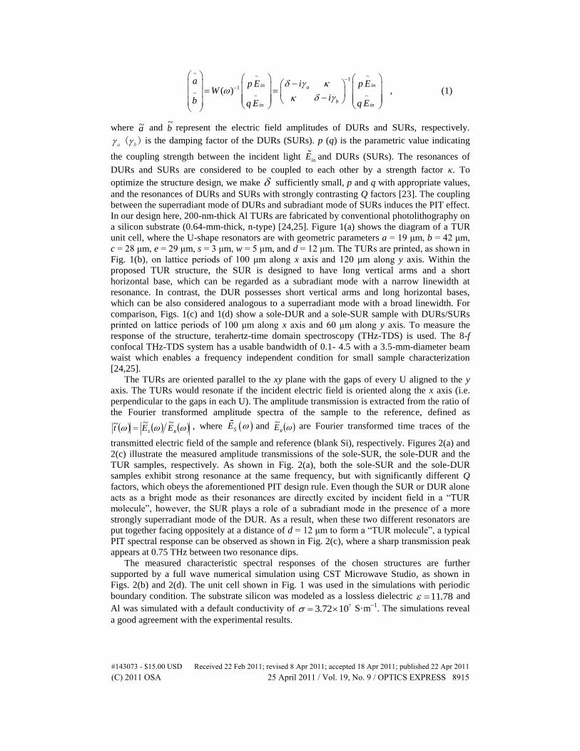
To highlight the underling physics of the measured spectra with varying separation d,
current densities and field distributions at the resonance transparency peak are given in Fig. 4.
It is evident that with reducing d, the current densities and electric field distributions in the
DURs change drastically. When the SUR and DUR are brought closer with reducing d, the
inner-arms of the DUR tend to couple more strongly with the arms of the SUR, causing the
suppression of currents in the SUR and enhancement of currents in the DUR. As shown in
#143073 - $15.00 USD Received 22 Feb 2011; revised 8 Apr 2011; accepted 18 Apr 2011; published 22 Apr 2011(C) 2011 OSA 25 April 2011 / Vol. 19, No. 9 / OPTICS EXPRESS 8916

Fig. 4, we observe that there is a gradual transfer of electromagnetic energy from the SUR to
the DUR. For the sample with d = 12 μm, most of the energy is concentrated in the SUR. As d
is decreased to 0 µm, the electromagnetic energy is distributed almost uniformly on the DUR
and the SUR. Further reducing d to 10 µm, more energy seems to be gradually transferred
from the SUR and localized only on DUR. Consequently, on one hand, the DUR becomes
highly radiative whereas on the other hand the resonance of SUR which acts as a subradiant
resonator is completely quenched, such that the PIT response disappears.
Fig. 3. (a) Measured and (b) simulated transmission spectra for different vertical separation distances d between the SUR and the DUR in the TUR unit cell.
In addition, another scheme is implemented by horizontally moving the position of SUR
atom in the TUR molecule. The measured spectra are shown in Fig. 5(a) for various relative
horizontal displacement distances h. The corresponding simulated spectra are well reproduced
in Fig. 5(b). As illustrated in Figs. 5(a) and 5(b), when h varies from 0 to 30 μm, we found
that the transmission peak is nearly undisturbed and no remarkable differences are observed.
In this case, we noticed that the surface current of each U-shape resonator in the DURs is
quite different, as shown in the inset of Fig. 5(b): the surface current of the right-U resonator
is considerably stronger than that of the left one. The distinct surface currents of these two U
resonators in the DUR further verify the opposite direction excitation provided by the
scattered electric field of the SUR (subradiant mode), which renders the right-U resonator in
the DUR to be strongly excited while the left one being in a more suppressed state due to the
superposition of excitation from the SUR and the external field.
#143073 - $15.00 USD Received 22 Feb 2011; revised 8 Apr 2011; accepted 18 Apr 2011; published 22 Apr 2011(C) 2011 OSA 25 April 2011 / Vol. 19, No. 9 / OPTICS EXPRESS 8917
Fig. 4. Current densities and electric field distributions of the proposed structures with various
d of 12, 0 and 10 μm, respectively.
In order to obtain more threads of the aforementioned modulation process in the PIT
spectra, we develop the coupling-mode theory as a function of the coupled circuit parameters,
where the coupled resonators are modeled by the equivalent RLC circuits [7,13]. Figure 5(c)
shows the equivalent RLC circuits: two RLC resonators P1 and P2 are coupled by a common
effective capacitor CC [27,28]. The inductive coupling between the RLC resonators has not
been considered here as the magnetic coupling between the closely spaced SRRs are very
weak [29]. Here P1 (P2) represents the equivalent circuit resonator of DUR (SUR) and CC
represents the equivalent coupling function between the two modes. The voltage sources in
the upper and lower subcircuits correspond to the external incident field. The resonance
currents I1 and I2 circulating in P1 and P2 circuit loops can be calculated based on standard
loop current analysis:
,
1
1
1
1
)(~
~
1
1
11
1
11
~
~
1
~
~
2
1
in
inC
C
in
in
Uq
Up
CjRLj
Cj
Cj
CjRLj
Uq
UpZ
I
I
(2)
By comparing Eqs. (1) with (2), we note that the coupling matrix W is proportional to the
impedance matrix Z and the coupling strength factor k is proportional to1
Cj C. In the first
case involving decrease of d, the common effective capacitance CC is increased due to
decreased effective distance between equivalent capacitance plates of the DUR and the SUR.
Consequently, we have a reduced coupling factor k with decreasing d. Since the coupling
between the DUR and SUR is reduced in spite of the close physical proximity of the
resonators, the DUR is free from the suppressed state, making it highly radiative while the
#143073 - $15.00 USD Received 22 Feb 2011; revised 8 Apr 2011; accepted 18 Apr 2011; published 22 Apr 2011(C) 2011 OSA 25 April 2011 / Vol. 19, No. 9 / OPTICS EXPRESS 8918

currents in SUR completely disappear, quenching its fundamental resonance, thus leading to
the disappearance of the PIT peak. When we vary the horizontal displacement parameter h,
neither the effective vertical distance nor the dimension of capacitance plates is significantly
altered, so the pronounced PIT spectra do not display any significant changes.
Fig. 5. (a) Measured and (b) simulated transmission spectra for different horizontal movement h. The inset of (b) is the surface current oscillation of the asymmetric TUR induced by
horizontal displacement. (c) The equivalent RLC circuits.
3. Conclusion
In conclusion, we experimentally and numerically demonstrate that the TUR metamaterial
consisting of the SUR and DUR constituent resonators exhibits a tunable PIT spectral
response at terahertz frequencies. The effects of vertical and horizontal separations between
the resonators on the PIT behaviors are systematically studied, indicating that the PIT spectral
response can be engineered by varying the relative vertical distance between the subradiant
and superradiant resonators. A counterintuitive phenomenon is observed, i.e. when the
subradiant and superradiant resonators were brought closer to each other in the vertical
direction, the transparency peak begins to gradually disappear beyond a critical distance of
separation. This effect is mainly due to complete suppression of resonance in the subradiant
resonators and enhanced radiative nature of the superradiant resonators as they are coupled at
a close vertical distance. In the case of horizontal displacement, however, the transparency
peak remains uninterrupted as the field distributions are not affected. The vertical coupling
effect can tune the PIT behavior and thus could lead to promising applications in slow light
devices in the terahertz regime.
Acknowledgments
This work was supported by the National Natural Science Foundation of China (NSFC)
(Grant Nos. 61028011, 61007034, and 60977064), the U.S. National Science Foundation, the
Tianjin Sci-Tech Program (Grant Nos. 09ZCKFGX01500 and 10JCYBJC01400), and the
MOE 111 Program of China (Grant No. B07014).
#143073 - $15.00 USD Received 22 Feb 2011; revised 8 Apr 2011; accepted 18 Apr 2011; published 22 Apr 2011(C) 2011 OSA 25 April 2011 / Vol. 19, No. 9 / OPTICS EXPRESS 8919